1
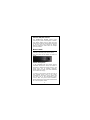
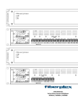
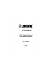
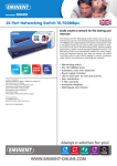
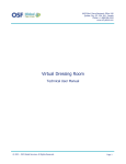
24-P + 2-SFP Gigabit Ethernet Switch User Manual V1.0 FCC Certifications This Equipment has been tested and found to comply with the limits for a Class A digital device, pursuant to part 15 of the FCC Rules. These limits are designed to provide reasonable protection against harmful interference when the equipment is operated in a commercial environment. This equipment generates, uses, and can radiate radio frequency energy and, if not installed and used in accordance with the instruction manual, may cause harmful interference to radio communications. Operation of this equipment in a residential area is likely to cause harmful interference in which case the user will be required to correct the interference at his own expense. This device complies with Part 15 of the FCC Rules. Operation is subject to the following two conditions: (1) this device may not cause harmful interference, and (2) this device must accept any interference received; including interference that may cause undesired operation. CE Mark Warning This equipment complies with the requirements relating to the EMC Directive 2004/108/EC, the Low Voltage Directive 2006/95/EC, and the RoHS Directive 2011/65/EU. Company has an on-going policy of upgrading its products and it may be possible that information in this document is not up-to-date. Please check with your local distributors for the latest information. No part of this document can be copied or reproduced in any form without written consent from the company. Trademarks: All trade names and trademarks are the properties of their respective companies. Copyright © 2014, All Rights Reserved. Unpacking Information Thank you for purchasing this product. Before installation, please verify that your package contains the following items. 1. 2. 3. 4. 5. One 24-Port Gigabit Ethernet switch with 2 SFP ports One AC power cord Rack-mount bracket x2 Rubber foot x4 and screws One user manual Introduction Easily boost your networking throughput, the rack-mountable switch provides you 24 10/100/1000Mbps ports that lead you to a real Gigabit connection. Users are now able to transfer large and high bandwidth-needed files faster and hence get a real efficiency improvement. In addition to the cooper ports, 2 ports support fiber connection with the 2 equipped Mini-GBIC ports for obtaining long-distance communication. The switch offers users with fast and reliable network. The store-and-forward architecture filters errors and forwards packets in a non-blocking environment. Flow control ensures the correctness of data transmitting. The 802.3x and backpressure flow control mechanisms work respectively for full and half duplex modes. The switch features with easy installation and maintenance. It supports N-Way auto-negotiation protocol, which detects the networking speed (either 10/100/1000 Mbps) and the duplex modes (Full or Half duplex mode) automatically and do an immediately adjustment to advance the capability and performance. Auto-MDI/MDI-X function alleviates the effort to use crossover cables. Users need not to prepare crossover cables for equipment connectivity. Also, rich diagnostic LEDs are provided for users to get real-time information of the connection status that helps to do quick response and correction. Key Feature Complies with 10BASE-T specifications of the IEEE802.3 standard Complies with 100BASE-TX specifications of the IEEE802.3u standard Complies with 1000BASE-T specifications of the IEEE802.3ab standard Complies with 1000BASE-X specifications of the IEEE802.3z standard Complies with IEEE802.3az Energy Efficient Ethernet Complies with IEEE 802.1p Cos 2 Supports back-pressure (half duplex) and flow control (IEEE 802.3x) Supports N-Way protocol for speed (10/100/1000Mbps) and duplex mode (Half/Full) auto-detection Supports MDI/MDI-X auto crossover and polarity correction Store-and-forward architecture filters fragment & CRC error packets Push on/off button to enable/disable IEEE802.3az Provides 2 SFP ports for optional fiber connection Supports 8K entries MAC address Support 4.1M bit buffer memory Support 10K bytes jumbo frames Supports extensive LED indicators for network diagnostics Rack mountable Internal power supply 100~240V AC/50~60Hz universal input EMC: FCC, CE Class A Safety: LVD EN60950-1 3 Front Panel The front panel of the switch contains RJ45 ports, LEDs, 2 SFP ports and IEEE802.3az EEE ON/OFF button. detailed LED definition, please refer to next paragraph. the an For the The front panel of the switch is shown as below: LEDs Definition This switch contains one power LED and Link/Act LEDs that shows the activities and information of the ports. LED Power Status Operation Steady Green The switch is powered on Off The switch is powered off Steady Green Valid port connection Link/ ACT Valid port connection and Blinking Green there is data transmitting/ receiving Off Port disconnected 4 RJ-45 Ports All the RJ-45 ports in the device are auto-negotiating and auto-crossover. An auto-negotiating port can detect and adjust to the optimum Ethernet speed (10/100/1000 Mbps) and duplex mode (full duplex or half duplex) of the connected device. An auto-crossover (auto-MDI/MDI-X) port automatically works with a straight-through or crossover Ethernet cable. Mini-GBIC Slots There are two slots for mini-GBIC (Gigabit Interface Converter) transceivers. You can plug the SFP port modules into the switch. The SPF port modules are to be used with fiber-optical transceiver cabling in order to uplink various other networking devices for a gigabit link that may span great distances. You can change transceivers while the switch is operating and use different transceivers to connect to Ethernet switches with different types of fiber-optic or even copper cable connectors. The SFP modules is a hot-pluggable transceiver and specified by a multi-source agreement (MSA). See the SFF committee’s INF-8074i specification Rev 1.0 for details. 5 802.3az ON/OFF button: The IEEE802.3az ON/OFF button helps reducing the power consumption of switch. This button allows users to keep the best performance without transmission impacted or to have the green support of Energy Efficient Ethernet mode with the simple push of a button. Rear Panel The three-pronged power receptacle located on the rear panel of the switch. is The rear panel of the switch is shown as below. Power Receptacle To be compatible with the electric service standards around the world, the switch is designed to afford the power supply in the range from 100 to 240VAC, 50/60Hz. Please make sure that your outlet standard to be within this range. To power on the switch, connect one end of the supplied power cord to the power receptacle on the back of the switch and the other end to the appropriate power source. After the power cord installation, please check if the power LED is illuminated for a normal power status. 6 Installation This switch can be placed on your desktop directly, or mounted in a rack. The installation is a snap. Users can use all the features of the switch with simply attaching the cables and turning the power on. Before installing the switch, we strongly recommend: 1. The switch is placed with appropriate ventilation environment. A minimum 25mm space around the unit is recommended. 2. The switch and the relevant components are away from sources of electrical noise such as radios, transmitters and broadband amplifiers. 3. The switch is away from environments beyond recommend moisture. Desktop Installation 1. Attach the provided rubber feet to the bottom of the switch to keep the switch from slipping. The recommend position has been square-marked. 2. Install the switch on a level surface that can support the weight of the unit and the relevant components. 3. Plug the switch with the female end of the provided power cord and plug the male end to the power outlet. 7 Rack-mount Installation The switch may standalone, or may be mounted in a standard 19” rack. Rack mounting produces an orderly installation when you have a number of related network devices. The switch is supplied with two optional rack mounting brackets and screws, which are used for rack mounting the unit. Rack-mount Installation Requirements: 1. Two mounting brackets. 2. Six M3 flat head screws Procedures to Rack-Mount the switch in the rack: 1. First disconnect all the cables from the switch. 2. Place the unit the right way up on a hard, flat surface with the front facing you. 3. Locate a mounting bracket over the mounting holes on one side of the unit. 4. Insert the screws and fully tighten with a suitable screwdriver. 5. Repeat the two previous steps for the other side of the unit. 6. Insert the unit into the rack with suitable screws. 7. Reconnect all the cables. 8 Network Cables 1. Crossover or straight-through cable: All the ports on the switch support Auto-MDI/MDI-X functionality. Both straight-through or crossover cables can be used to connect the switch with PCs as well as other devices like switches, hubs or router. 2. Category 3, 4, 5, 5e, 6 UTP/STP cable: To make a valid connection and obtain the optimal performance. Appropriate cables corresponding to different transmitting/receiving speed is required. To choose a suitable cable, please refer to the following table. Media Speed (Mbps) 10 10/100/1000 100 Mbps copper 1000 1000Mbps Fiber (Mini GBIC required) 1000 Wiring Category3,4,5 UTP/STP Category 5 UTP/STP Category5e,6 UTP/STP The cable type differs from the mini-GBIC you purchase. Please refer to the instruction that came with your mini-GBIC. 9 Product Specifications Standard Interface Cable Connections Network Data Rate Transmission Mode LED Indications Memory Jumbo Frame Temperature Humidity Power Supply EMC Safety IEEE802.3 (10BASE-T) IEEE802.3u (100BASE-TX) IEEE802.3ab (1000BASE-T) IEEE 802.3z (1000Base-X) IEEE802.3x full-duplex flow control IEEE 802.3az Energy Efficient Ethernet IEEE 802.1p Cos 24x10/100/1000Mbps RJ-45 ports 2xMini-GBIC open slots 1x IEEE802.3az push button RJ-45 (10BASE-T): Category 3,4,5 UTP/STP RJ-45 (100BASE-TX): Category 5 UTP/STP RJ-45 (1000BASE-T): Category 5e,6 UTP/STP Fiber: depend on Mini-GBIC types 10/100/1000 Mbps Auto-negotiation 10/100Mbps:Full-duplex,Half-duplex 1000Mbps: Full-duplex System: Power Ports: Link/ACT 8K MAC entries 4.1M bit buffer memory 10K bytes Operating: 0~50℃(32°~122°F) Operating: 10%~90%, non-condensing Internal power supply FCC,CE Class A LVD EN60950-1 10