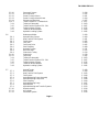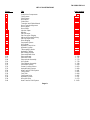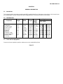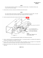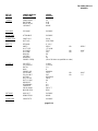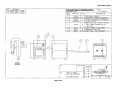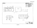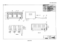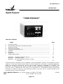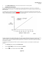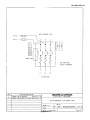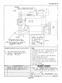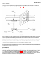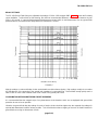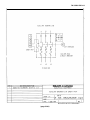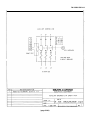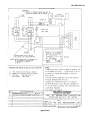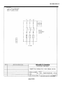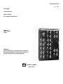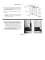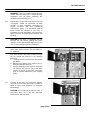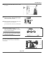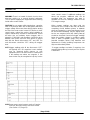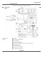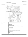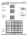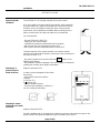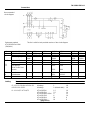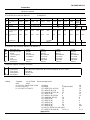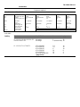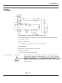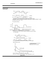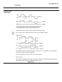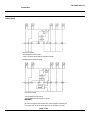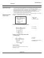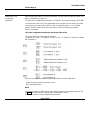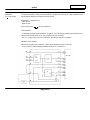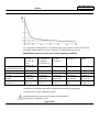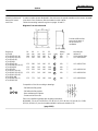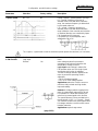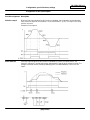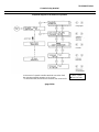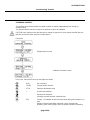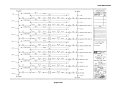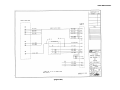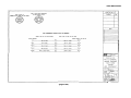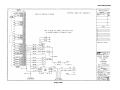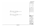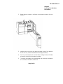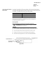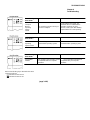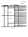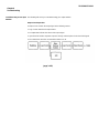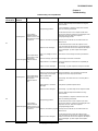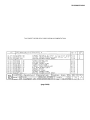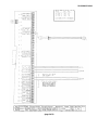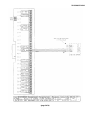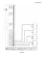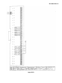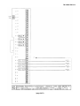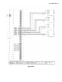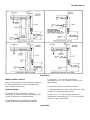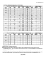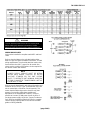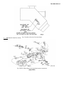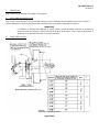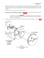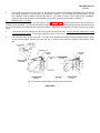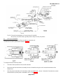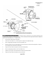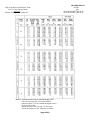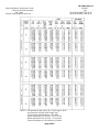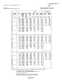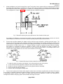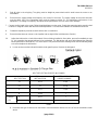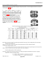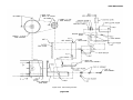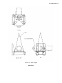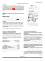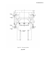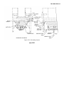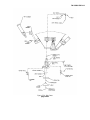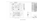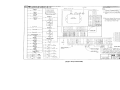
1
TM 5-3895-374-24-1 TECHNICAL MANUAL MAINTENANCE Volume 1 M081 ASPHALT MIXING PLANT NSN 3895-01-369-2551 Manufactured by WRT Equipment Ltd. 818 43rd Street East Saskatoon, Saskatchewan Canada S7K 3V1 Contract DAAE07-92-C-1191 DISTRIBUTION STATEMENT A: Approved for public release; distribution unlimited. HEADQUARTERS DEPARTMENT OF THE ARMY 1 NOVEMBER 1995 TM 5-3895-374-24-1 TECHNICAL MANUAL TM 5-3895-374-24-1 HEADQUARTERS, DEPARTMENT OF THE ARMY Washington, D.C. 1 November 1995 Unit, Direct Support and General Support Maintenance Manual for ASPHALT MIXING PLANT NSN 3895-01-369-2551 REPORTING OF ERRORS AND RECOMMENDING IMPROVEMENTS You can help Improve this manual If you find any mistakes or If you know of a way to improve the procedures, please let us know. Mall your letter, DA Form 2028 (Recommended changes to Publications and Blank Forms), or DA Form 20282, located in the back of this manual, direct to: Commander, US Army Tank-automotive and Armaments Command, ATTN: AMSTA-IM-MMAA, Warren Ml 48397-5000. A reply will be furnished to you. You may also provide DA Form 2028-2 information to TACOM via datafax or e-mail. TACOM’s datafax number for AMSTA-IM-MMAA is (810)574-6323 and the e-mail address is: [email protected] army.mil THIS MANUAL SET CONSISTS OF THE FOLLOWING: VOLUME 1 VOLUME 2 VOLUME 3 VOLUME 4 OPERATOR’S MANUAL MAINTENANCE MANUAL MAINTENANCE MANUAL PARTS MANUAL TM 5-3895-374-10 TM 5-3895-374-24-1 TM 5-3895-374-24-2 TM 5-3895-374-24P The Maintenance information for the Asphalt Mixing Plant (AMP) is contained in two volumes, TM 5-3895-374-24-1 AND TM 5-3895-374-24-2 Each volume contains a table of contents that covers both volumes and shows where volume 1 ends and volume 2 starts. make sure you have both volumes with you when performing maintenance. This maintenance manual is an Army authentication of a commercial manual. The manual Is not formatted to Department of the Army specifications This manual does contain the information needed to perform maintenance on the AMP. You will find some pages In this manual have two pages numbers, one In parenthesis. The page number contained In the parenthesis Is the true page number that tracks with the table of contents.The page number not In the parenthesis Is a page number that exists in the commercial vendor manual as It appears In commercial use. This commercial page number has been left on the page to maintain continuity with the internal page referencing of the commercial vendor sections. Refer to TB 5-3895-374-14 for any Warranty Issues This TB takes precedence over all vendor warranty information that may appear in this manual Page i TM 5-3895-374-24-1 TABLE OF CONTENTS VOLUME 1 - TM 5-3895-374-24-1 Cover Page Manual Set Listing Table of Contents i ii List of Illustrations Safety Summary viii xii CHAPTER 1 GENERAL INFORMATION Paragraph 1-1 1-2 1-3 Title INTRODUCTION Tabulated Data Tools and Test Equipment Page Number 1-1 1-1 1-1 CHAPTER 2 PREPARATION FOR USE BY RECEIVING ACTIVITY Paragraph 2-1 2-2 2-3 Title General Lubrication Visual Inspection Page Number 2-1 2-1 2-2 Page ii TM 5-3895-374-24-1 CHAPTER 3 MAINTENANCE INSTRUCTIONS Paragraph 3-1 General 3-1-1 3-2 Title Removal, Repair, and Replacement Page Number 3-1 3-1 3-2-1 3-2-2 3-2-3 3-2-4 3-2-5 3-2-6 3-2-7 3-2-8 3-2-9 3-2-10 3-2-11 3-2-12 3-13-2 3-14 3-15 3-16 3-17 Control Van Burner Control Damper Control Asphalt Calibration Scale Weight Indicator Motor Control Center Variable Speed Drives Electrical Schematics Data Table Access Module Programmable Logic Controller Blending Controller Printer Environmental Control Unit Timers Trailer Suspension - Tandem Axle Trailer Axle Assembly Trailer Electrical System 12V - 24V Trailer Air Brake System Trailer 5th Wheel Adapter 3-3 3-5 3 - 31 3 - 51 3 - 79 3 - 149 3 - 272 3 - 394 3 - 409 3 - 467 3 - 479 3- 482 3 - 493 3 - 1357 3 - 1363 3 -1367 3 - 1375 3 - 1383 3-3-1 3-3-2 3-3-3 3-3-4 3-3-5 3-3-6 3-3-7 3-3-8 3-3-9 3-3-10 3-3-11 3-3-12 3-3-13 3-3-14 3-13-3 3-14 Drum Mixer Burner and Blower Assembly Fuel System Pilot System Drum Drive Gear Reducer Shaft Coupling Chain Oiler Trunnions and Guide Wheels Drum Trunnion Alignment Drum Flights Drum Seals Asphalt/Fines Injection Pipes Pillow Block - Spilt Housing Sheaves and Bushings Trailer Suspension - Triple Axle Trailer Axle Assembly 3 - 494 3 - 494 3 - 554 3 - 555 3 - 556 3 - 562 3 - 570 3 - 573 3 - 575 3 - 577 3 - 580 3 - 580 3 - 581 3 - 585 3 - 592 3 - 1360 3 - 1363 3-3 Page iii TM 5-3895-374-24-1 3-15 3-16 3-17 3-18 Trailer Electrical System 12V - 24V Trailer Air Brake System Trailer 5th Wheel Adapter Hydraulic Leveling System 3 - 1367 3 - 1375 3 - 1383 3 - 1385 3-4-1 3-4-2 3-4-3 3-4-4 3-4-5 3-4-6 3-4-7 3-4-8 3-4-9 3-4-10 3-4-11 3-4-12 3-4-13 3-4-14 3-4-15 3-4-16 3-13-3 3-14 3-15 3-16 3-17 3-18 Surge Bin Batcher Slat Conveyor Slat Conveyor Drive Slat Conveyor Gear Reducer Shaft Coupling Pneumatic System Air Compressor Air Cylinder Hydraulic Pump Drive Hydraulic System Telescoping Cylinder Hydraulic Cylinder Bin Heating System Bin Gates Electrical Panel Tail Shaft Bearing Trailer Suspension - Triple Axle Trailer Axle Assembly Trailer Electrical System 12V - 24V Trailer Air Brake System Trailer 5th Wheel Adapter Hydraulic Leveling System 3 - 595 3 - 595 3 - 598 3 - 607 3 - 613 3 - 620 3 - 623 3 - 624 3 - 641 3 - 642 3 - 646 3 - 647 3 - 649 3 - 651 3 - 653 3 - 656 3 - 657 3 - 1360 3 - 1363 3 - 1367 3 - 1375 3 - 1383 3 - 1385 3-4 VOLUME 2 - TM 5-3895-374-24-2 3-5 3-5-1 3-5-2 3-5-3 3-5-4 3-5-5 3-5-6 3-5-7 3-5-8 3-5-9 Baghouse Griffin Baghouse Exhaust Blower Drive Exhaust Blower Exhaust Louver Exhaust Inlet Assembly Air Cylinder Gear Reducers, Screw Conveyors Fines Blower Assembly Fines Blower Page iv 3 - 660 3 - 660 3 - 764 3 - 765 3 - 769 3 - 772 3 - 776 3 - 779 3 - 796 3 - 799 TM 5-3895-374-24-1 3-5-10 3-5-11 3-5-12 3-5-13 3-5-14 3-13-2 3-14 3-15 3-16 3-17 3-18 Pneumatic System Air Compressor Screw Conveyor Drives Screw Conveyor Motor Mounts Sheaves and Bushings Trailer Suspension - Tandem Axle Trailer Axle Assembly Trailer Electrical System 12V - 24V Trailer Air Brake System Trailer 5th Wheel Adapter Hydraulic Leveling System 3 - 824 3 - 825 3 - 851 3 - 854 3 - 857 3 - 1357 3 - 1363 3 - 1367 3 - 1375 3 - 1383 3 - 1385 3-6-1 3-6-2 3-6-3 3-6-4 3-6-5 3-6-6 3-6-7 3-6-8 3-6-9 3-6-10 3-6-11 3-14 3-15 3-16 3-17 3-18 Dedrummer/Melter Asphalt Piping System Heat Transfer Fluid System Fuel System Fuel Tank Fuel Pump Drive Shaft Coupling Hydraulic System Drum Lift Hoist Chain Hoist Trolley Chain Hoist Fuel Pump Trailer Axle Assembly Trailer Electrical System 12V - 24V Trailer Air Brake System Trailer 5th Wheel Adapter Hydraulic Leveling System 3 - 860 3 - 860 3 - 861 3 - 862 3 - 863 3 - 865 3 - 868 3 - 871 3 - 872 3 - 874 3 - 878 3 - 895 3 - 1363 3 - 1367 3 - 1375 3 - 1383 3 - 1385 3-7-1 3-7-2 3-7-3 3-7-4 3-7-5 3-7-6 3-7-7 3-7-8 3-7-9 3-7-10 3-7-11 3-7-12 Asphalt Tanker Hot Oil Heater Heat Transfer Fluid System Fuel System Asphalt Metering Pump Assembly Asphalt Metering Pump Drive Shaft Coupling Asphalt Metering Pump Asphalt Meter Asphalt Metering and Transfer Systems Divert Assembly Air Cylinder Pneumatic System 3 - 900 3 - 900 3 - 1183 3 - 1184 3 - 1185 3 - 1188 3 - 1194 3 - 1197 3 - 1210 3 - 1223 3 - 1224 3 - 1225 3 - 1229 3-6 3-7 Page v TM 5-3895-374-24-1 3-7-13 3-7-14 3-7-15 3-7-16 3-13-2 3-14 3-15 3-16 3-17 3-18 Asphalt Transfer Pump Drive Calibration Tank/System Gear Reducer Sheaves and Bushings Trailer Suspension - Tandem Axle Trailer Axle Assembly Trailer Electrical System 12V - 24V Trailer Air Brake System Trailer 5th Wheel Adapter Hydraulic Leveling System 3 - 1230 3 - 1233 3 - 1235 3 - 1236 3 - 1357 3 - 1363 3 - 1367 3 - 1375 3 - 1383 3 - 1385 3-8-1 3-8-2 3-8-3 3-8-4 3-8-5 3-8-6 3-8-7 3-8-8 3-8-9 3-8-10 3-8-11 3-8-12 3-13-1 3-14 3-15 3-16 3-17 Feed Conveyor Screen Deck Conveyor Head Pulley Conveyor Assembly Conveyor Belt, Idler Pulleys and Adjustments Belt Scale, Speed Sensor Hydraulic System Gear Reducer, Conveyor Screen Adjustment Conveyor Drive Sheaves and Bushings Belt Fasteners Hydraulic Cylinder Trailer Suspensions - Single Axle Trailer Axle Assembly Trailer Electrical System 12V - 24V Trailer Air Brake System Trailer 5th Wheel Adapter 3 - 1239 3 - 1239 3 - 1244 3 - 1247 3 - 1253 3 - 1258 3 - 1276 3 - 1277 3 - 1286 3 - 1289 3 - 1292 3 - 1295 3 - 1298 3 - 1354 3 - 1363 3 - 1367 3 - 1375 3 - 1383 3-9-1 3-9-2 3-9-3 3-9-4 3-9-5 3-9-6 3-9-7 3-9-8 3-9-9 3-9-10 3-9-11 3-9-12 Four Bin Feeder Belt Feeder Drives Gear Reducer Feed Gate Feeder Flow Switch Belt Feeder Bin Vibrators Gathering Conveyor Gathering Conveyor Drive Shaft Coupling Conveyor Belt, Idler Pulleys and Adjustments Hydraulic System Sheaves and Bushings 3 - 1300 3 - 1300 3 - 1303 3 - 1304 3 - 1306 3 - 1309 3 - 1314 3 - 1318 3 - 1326 3 - 1329 3 - 1332 3 - 1332 3 - 1333 3-8 3-9 Page vi TM 5-3895-374-24-1 3-9-13 3-9-14 3-13-2 3-14 3-15 3-16 3-17 3-18 Hydraulic Cylinder Belt Fasteners Trailer Suspensions - Tandem Axle Trailer Axle Assembly Trailer Electrical System 12V - 24V Trailer Air Brake System Trailer 5th Wheel Adapter Hydraulic Leveling System 3 - 1336 3 - 1338 3 - 1357 3 - 1363 3 - 1367 3 - 1375 3 - 1383 3 - 1385 3-13-2 3-14 3-15 3-16 Dolly Trailer Suspensions - Tandem Axle Trailer Axle Assembly Trailer Electrical System 12V - 24V Trailer Air Brake System 3 - 1341 3 - 1357 3 - 1363 3 - 1367 3 - 1375 3-13-2 3-14 3-15 3-16 3-17 Generator Trailer Trailer Suspensions - Tandem Axle Trailer Axle Assembly Trailer Electrical System 12V - 24V Trailer Air Brake System Trailer 5th Wheel Adapter 3 - 1341 3 - 1357 3 - 1363 3 - 1367 3 - 1375 3 - 1383 3-12 3-12-1 3-12-2 3-12-3 Hydraulic Power Pack Pump Drive Hydraulic System Shaft Coupling 3 - 1341 3 - 1341 3 - 1345 3 - 1346 3-13-1 3-13-2 3-13-3 3-14 3-15 3-16 3-16-1 3-16-2 3-16-3 3-17 3-18 3-18-1 Trailer Suspensions Trailer Suspensions - Single Axle Trailer Suspensions - Tandem Axle Trailer Suspensions - Triple Axle Trailer Axle Assembly Trailer Electrical System 12V - 24V Trailer Air Brakes Trailer Air Brake System Brake Adjustment Mechanical Release 5th Wheel Adapter Hydraulic Leveling System Hydraulic Cylinder 3 - 1349 3 - 1354 3 - 1357 3 - 1360 3 - 1363 3 - 1367 3 - 1375 3 - 1375 3 - 1375 3 - 1376 3 - 1383 3 - 1385 3 - 1385 3-10 3-11 3-13 Page vii TM 5-3895-374-24-1 CHAPTER 4 TROUBLE SHOOTING AND PMCS Page Number Paragraph Title 4-1 4-2 4-3 4-4 General Commercial Trouble Shooting Information Production Trouble Shooting Control Van/Controls Asphalt Display (Screen) Motor Controls Temperature Device Control Panel Programmable Logic Controller (PLC) Blending Controller Surge Bin Aggregate Feed Baghouse Burner Control System Interlocks Control Logic Charts Unit Preventive Maintenance Checks and Service 4-4-1 4-4-2 4-4-3 4-4-4 4-4-5 4-4-6 4-5 4-6 4-7 4-8 4-9 4-10 4-11 4-1 4-1 4-2 4-4 4-4 4-5 4-7 4-7 4-8 4-9 4 - 18 4 - 20 4 - 22 4 - 23 4 - 23 4 - 24 4 - 38 APPENDIX Page Number Paragraph Title A REFERENCES Scope Department of the Army Pamphlets Forms Field Manuals Technical Bulletins Technical Manuals Other Publications A-1 A-1 A-1 A-1 A-1 A-2 A-2 A-2 MAINTENANCE ALLOCATION CONCEPT B-1 A-1 A-2 A-3 A-4 A-5 A-6 A-7 B Page viii TM 5-3895-374-24-1 LIST OF ILLUSTRATIONS Figure Title 3-1 3-2 3-3 3-4 3-5 3-6 3-7 3-8 3-9 3-10 3-11 3-12 3-13 3-14 3-15 3-16 3-17 3-18 3-19 3-20 3-21 3-22 3-23 3-25 3-26 3-27 3-28 3-29 3-30 3-31 3-32 3-33 3-34 3-35 3-36 3-37 3-38 3-39 3-40 Control Van Components Fuel System Pilot System Drum Drive Chain Oiler Trunnions and Guide Wheels Drum Trunnion Alignment Drum Flights Drum Seals Injection Pipes Batcher Slat Conveyor Slat Conveyor Slinging Idler and Sprocket Spacing Slat Conveyor Drive Drive Slinging Pneumatic System Air Cylinder Hydraulic Pump Drive Hydraulic System Telescoping Cylinder Hydraulic Cylinder Bin Heating System Exhaust Blower Drive Exhaust Blower Exhaust Louver Exhaust Inlet Assembly Air Cylinder Fines Blower Assembly Pneumatic System Screw Conveyor Drives Asphalt Piping System Heat Transfer Fluid System Fuel System Fuel Tank Fuel Pump Drive Hydraulic System Drum Lift Hoist Heat Transfer Fluid System Page Number 3-4 3 - 554 3 - 555 3 - 557 3 - 574 3 - 576 3 - 578 3 - 582 3 - 583 3 - 584 3 - 596 3 - 599 3 - 602 3 - 604 3 - 610 3 - 611 3 - 623 3 - 643 3 - 645 3 - 646 3 - 648 3 - 650 3 - 652 3 - 766 3 - 768 3 - 771 3 - 773 3 - 778 3 - 798 3 - 824 3 - 853 3 - 860 3 - 861 3 - 862 3 - 864 3 - 867 3 - 871 3 - 873 3 - 1183 Page ix TM 5-3895-374-24-1 3-41 3-42 3-43 3-44 3-45 3-46 3-47 3-48 3-49 3-50 3-51 3-52 3-53 3-54 3-55 3-56 3-57 3-58 3-59 3-60 3-61 3-62 3-63 3-64 3-65 3-66 3-67 3-68 3-69 3-70 3-71 3-72 3-73 3-74 3-75 3-76 3-77 3-78 3-79 3-80 3-81 3-82 3-83 Fuel System Asphalt Metering Pump Assembly Asphalt Metering Pump Fittings Asphalt Metering Pump Drive Asphalt Metering and Transfer Systems Divert Assembly Air Cylinder Pneumatic System Asphalt Transfer Pump Drive Calibration Tank/System Screen Deck Conveyor Head Pulley Conveyor Assembly Belt Training Hydraulic System Conveyor Drive Hydraulic Cylinder Belt Feeder Drive Feed Gate Feeder Flow Switch Feeder Flow Switch Position Belt Feeder Bin Vibrators Gathering Conveyor Tail Section Gathering Conveyor Fold Section Gathering Conveyor Head Section Gathering Conveyor Drive Hydraulic System Hydraulic Cylinder Pump Drive Hydraulic System Trailer Axle Assembly Trailer Electrical System 12V - 24V Trailer Electrical System 12V - 24V Trailer Electrical System 12V - 24V Trailer Electrical System 12V - 24V Trailer Electrical System 12V - 24V Trailer Electrical System 12V - 24V Trailer Electrical System 12V - 24V Trailer Air Brake System Trailer Air Brake System Trailer Air Brake System Trailer Air Brake System Page x 3 - 1184 3 - 1186 3 - 1189 3 - 1190 3 - 1223 3 - 1226 3 - 1227 3 - 1229 3 - 1231 3 - 1234 3 - 1243 3 - 1245 3 - 1248 3 - 1257 3 - 1276 3 - 1291 3 - 1299 3 - 1301 3 - 1305 3 - 1307 3 - 1308 3 - 1310 3 - 1315 3 - 1319 3 - 1321 3 - 1323 3 - 1328 3 - 1332 3 - 1337 3 - 1344 3 - 1345 3 - 1364 3 - 1368 3 - 1369 3 - 1370 3 - 1371 3 - 1372 3 - 1373 3 - 1374 3 - 1377 3 - 1378 3 - 1379 3 - 1380 TM 5-3895-374-24-1 3-84 3-85 3-86 3-87 3-88 3-89 4-1 4-2 4-3 4-4 4-5 4-6 4-7 4-8 4-9 4-10 4-11 4-12 4-13 Trailer Air Brake System Trailer Air Brake System 5th Wheel Adapter Hydraulic Leveling System Hydraulic Leveling System Hydraulic Cylinder Start Up Control MCC Power to Motor Control Asphalt Metering Pump Baghouse Motor Controls Feed Motor Controls Batcher Control Baghouse Exhaust Shutter Motor Alarms Motor Alarm Silence Reset Asphalt Metering Pump Auto Reset Alarms Alarm Silence/Reset 3 - 1381 3 - 1382 3 - 1384 3 - 1386 3 - 1387 3 - 1389 4 - 25 4 - 26 4 - 27 4 - 28 4 - 29 4 - 30 4 - 31 4 - 32 4 - 33 4 - 34 4 - 35 4 - 36 4 - 37 Page xi TM 5-3895-374-24-1 SAFETY SUMMARY The following warnings and cautions apply to this technical manual. The applicable warnings and cautions are repeated within this text. WARNING Do not operate equipment before reading all technical manuals. the operation of this equipment by untrained personnel is potentially hazardous. WARNING Frequent inspection of equipment, safety devices and working areas must be performed. operational and personnel safety. Correct potential or actual hazards. Ensure WARNING Be sure electrical ground connections are made properly and firmly before any operations begin. CAUTION If any cleaning solvents or cleaners are used be aware of the safety precautions of these products. Most are both toxic and flammable. Keep off skin and use only in a well ventilated area in accordance with the manufacturers recommendations. Page xii TM 5-3895-374-24-1 WARNING High voltage is used in the operation of this equipment. Death on contact may result if personnel fall to observe safety precautions. DO NOT contact high voltage connections when installing or operating this equipment. WARNING Various fuels and lubricants used in the Asphalt Mixing Plant are toxic and flammable. Skin and eye protection are required. When adding hydraulic oil, nitrile or neoprene gloves and chemical resistant glasses must be worn to limit the chance of skin and eye contact with the oil. Good general ventilation is normally adequate. Keep away from open flame and other ignition sources. WARNING Remove watches, rings, and all other jewelry while working on or near this equipment These items could result in injury or death to personnel, or damage to equipment WARNING Use non-asbestos heat-resistant gloves, protective clothing and safety glasses when working with high temperatures. WARNING Do not perform repairs or maintenance to equipment while it is operating. Page xiii TM 5-3895-374-24-1 WARNING The following procedures must be followed when performing maintenance on the AMP. Failure to do so may result in injury or death. - Use of ear protection for all plant personnel working outside the control van. - Use of all safety devices and guards provided with the plant. - Personnel must wear the following protective items at all times. Coveralls (not loose fitting) Safety glasses with side shields Insulated gloves - non-asbestos Hard hat Safety shoes - Routine maintenance procedures must be followed at all times. Maintain all equipment in good operating condition. This includes but is not limited to; Fuel lines Asphalt lines Hot oil heating lines Hydraulic lines Electric cables and connectors Air lines - Restrict entry to all confined spaces except for authorized and scheduled maintenance inspections. Establish a confined space entry SOP IAW DHEW (NIOSH) Publication No. 80-106 (provided with AMP) when maintenance requires work in a confined space. This SOP must be coordinated with your local medical (preventive medicine) authority. Prior to entry, test for fumes and make provisions for adequate ventilation. Never work alone. Always use the buddy system when working in confined spaces. - Do not operate equipment in an enclosed area unless all exhaust fumes are safely vented away from the work area. - Army field manual (FM) 21-10 must be followed if the AMP is operated in conditions that expose its operators and maintainers to heat stress conditions. - USE COMMON SENSE NOTE You must be aware of and avoid the following potential hazards when operating and maintaining the AMP. Recommendations are included to provide the necessary information so these hazards can be avoid. Page xiv TM 5-3895-374-24-1 II. HAZARDS AND RECOMMENDATIONS Table 1-1. 1. HAZARD High voltage electrical Compressed air 2. Hazards and Recommendations Control Van DESCRIPTION RECOMMENDATION All electrical switch-gear are located In this unit and all power cables are attached to the power source In the van. The trailer air brake system Is comprised of air lines, tanks and valves which activate the trailer brakes. Operate and maintain in accordance with all safety procedures. Do not perform repair work without a qualified electrician. Maintain system In good operating condition. Release air pressure prior to repairing the system DESCRIPTION RECOMMENDATION Four Bin Feeder HAZARD Noise Operating machinery Aggregate materiels loaded into the four bin feeder by a front end loader may cause intermittent noise levels exceeding 85 dba. V-Belt drives and moving conveyor belts. High voltage electrical Power cables. Fluids under pressure Hydraulic cylinders, lines and valves. Page xv Use of ear protection. Use of guards during operation. Operator should not wear loose fitting clothing. Avoid contact when energized. Maintain in good condition. Use cable supports provided. Do not perform repair work without a qualified electrician. Maintain lines in good operating condition. Wear protective clothing while operating the plant. (gloves, coveralls, safety glasses, hard hat) TM 5-3895-374-24-1 HAZARD Compressed air DESCRIPTION RECOMMENDATION The trailer air brake system is comprised of air lines, tanks and valves which activate the trailer brakes. Maintain system in good operating condition. Release air pressure prior to repairing the system. DESCRIPTION RECOMMENDATION 3. Feed Conveyor HAZARD Compressed air The trailer air brake system is Maintain system in good Operating machinery Vibrating screen and moving conveyor belt. Noise Aggregate materiels discharged onto the screen may cause steady noise levels exceeding 85 dba. Power cables. Use of guards during operation. Operator should not wear loose fitting clothing. Use of ear protection. High voltage electrical Fluids under pressure Hydraulic cylinders, lines and valves. Compressed air The trailer air brake system Is comprised of air lines, tanks and valves which activate the trailer brakes. Avoid contact when energized. Maintain in good condition. Use cable supports provided. Do not perform repair work without a qualified electrician. Maintain lines in good operating condition. Wear protective clothing while operating the plant. (gloves, coveralls, safety glasses, hard hat) Maintain system in good operating condition. Release air pressure prior to repairing the system. DESCRIPTION RECOMMENDATION 4. Drum Mixer HAZARD Noise Aggregate materiels discharged into the feed chute may cause steady noise levels exceeding 85 dba. page xvi Use of ear protection. TM 5-3895-374-24-1 HAZARD DESCRIPTION Operating machinery The drum Is chain driven. High voltage electrical Power cables. Fluids under pressure Diesel fuel lines, asphalt pump and lines. Hydraulic cylinders, lines and valves. Compressed air The trailer air brake system is comprised of air lines, tanks and valves which activate the trailer brakes. The burner creates temperatures to 800° F. The drum, asphalt aggregate mixtures being discharged and exhaust gases will become hot (approximately 3000 F). Asphalt hot mix is discharged from the drum mixer. High temperature Fumes Flammable and combustible materiels The burner is a diesel fired unit. Liquid asphalt. Page xvii RECOMMENDATION Use of guards during operation. Operator should not wear loose fitting clothing Avoid contact when energized. Maintain In good condition. Use cable supports provided. Do not perform repair work without a qualified electrician. Maintain lines in good operating condition. Wear protective clothing while operating the plant. (gloves, coveralls, safety glasses, hard hat) Maintain system in good operating condition. Release air pressure prior to repairing the system. Wear protective clothing while operating the plant. (gloves, coveralls, safety glasses, hard hat, work boots) Avoid inhaling fumes and operating equipment In a confined area. Inspect and maintain burner safety systems as per manuals. Operate equipment with trained personnel. TM 5-3895-374-24-1 HAZARD Confined space DESCRIPTION RECOMMENDATION Repairs to the drum mixer will require work inside the drum Check drum for fumes prior to entry Use a fan for fresh air circulation Use motor control lock out device prior to entering the drum. Maintenance work may only be performed after proper safety procedures have been met DESCRIPTION RECOMMENDATION 5. Surge Bin HAZARD Noise Operating machinery High voltage electrical Intermittent noise levels exceeding 85 dba may be caused by: the drag slat conveyor elevating asphalt hot ix to the batcher, air compressor, exhausting air from air cylinders; and asphalt being discharged from the batcher to the bin or from the bin into trucks. The air compressor is belt driven. The drag slat conveyor is a chain with steel attached to it The chain runs on sprockets. The conveyor drive is chain driven. Power cables. Page xviii Use of ear protection Use of guards during operation. Operator should not wear loose fitting clothing Avoid contract when energized. Maintain in good condition. Use cable supports provided Do not perform repair work without a qualified electrician TM 5-3895-374-24-1 HAZARD Fluids under Hydraulic cylinders, lines and pressure Compressed air An air compressor is mounted on this unit and provides air at 125 psi to the gate cylinders An air tank Is part of the compressor The trailer air brake system Is comprised of air lines, tanks and valves which activate the trailer brakes Asphalt aggregate mixtures being discharged and exhaust gases will become hot (approximately 3000 F) Asphalt hot mix Is discharged from the slat conveyor High temperature Fumes 6. DESCRIPTION RECOMMENDATION Maintain lines In good valves operating condition Wear protective clothing while operating the plant (gloves, coveralls, safety glasses, hard hat) Maintain system In good operating condition Release air pressure prior to repairing the system Wear protective clothing while operating the plant (gloves, coveralls, safety glasses, hard hat) Avoid Inhaling fumes and operating equipment In a confined area Baghouse HAZARD Noise Operating machinery DESCRIPTION Steady noise levels exceeding 85 dba may be caused by. the air compressor, rotary exhaust fan and blower. The air compressor is belt driven The exhaust fan Is belt driven Page xix RECOMMENDATION Use of ear protection. Use of guards during operation Operator should not wear loose fitting clothing TM 5-3895-374-24-1 HAZARD DESCRIPTION RECOMMENDATION High voltage electrical Power cables Fluids under pressure Hydraulic cylinders, lines and valves Compressed air An air compressor is mounted on this unit and provides air at 95 psi An air tank is part of the compressor The trailer air brake system is comprised of air lines, tanks and valves which activate the trailer brakes. The air drawn from the drum into the baghouse is approximately 300° F High temperature Fumes The air drawn from the drum mixer may contain diesel and/or asphalt fumes Confined space 7. Avoid contact when energized Maintain in good condition Use cable supports provided Do not perform repair work without a qualified electrician. Maintain lines in good operating condition. Wear protective clothing while operating the plant. (gloves, coveralls, safety glasses, hard hat) Maintain system In good operating condition Release air pressure prior to repairing the system. Wear protective clothing while operating the plant (gloves, coveralls, safety glasses, hard hat) Avoid Inhaling fumes and operating equipment In a confined area. Restrict entry Generator Trailer HAZARD DESCRIPTION RECOMMENDATION Fumes The air drawn from the drum Avoid Inhaling fumes and Noise Steady noise levels exceeding 85 dba may be caused by the generators. Use of ear protection Page xx TM 5-3895-374-24-1 HAZARD High voltage electrical Produced by this equipment. Fluids under pressure Diesel lines and coolant hoses. Compressed air The trailer air brake system Is comprised of air lines, tanks and valves which activate the trailer brakes. Operation will generate heat. High temperature 8. DESCRIPTION Fumes Diesel exhaust may cause nausea or headaches. Flammable and combustible materiels The generators are diesel engine powered units. RECOMMENDATION Avoid contact when energized. Maintain in good condition. Use cable supports provided. Do not perform repair work without a qualified electrician. Maintain lines In good operating condition Wear protective clothing while operating the plant. (gloves, coveralls, safety glasses, hard hat) Maintain system in good operating condition Release air pressure prior to repairing the system. Wear protective clothing while operating the plant. (gloves, coveralls, safety glasses, hard hat) Avoid inhaling fumes and operating equipment In a confined area. Inspect and maintain generators as per manuals. Dedrummer/Melter HAZARD DESCRIPTION High temperature asphalt. Hot oil is used to melt the Operating machinery A electric chain hoist is operated to raise and position drums. Page xxi RECOMMENDATION Wear protective clothing while operating the plant (gloves, coveralls, safety glasses, hard hat) Use of guards during operation. Operator should not wear loose fitting clothing TM 5-3895-374-24-1 HAZARD High voltage electrical Power cables. Fluids under pressure Hydraulic cylinders, lines and valves. Diesel lines Heat transfer lines. Compressed air The trailer air brake system is comprised of air lines, tanks and valves which activate the trailer brakes. The asphalt tank is 10 feet in diameter with one manhole. Entry may be required to locate leaks in the heating coils and to effect repairs. A diesel tank is mounted on this unit. The liquid asphalt has a flash point of 4500 F. The heat transfer oil has a flash point of 540° F. Confined space Flammable and combustible materiels 9. DESCRIPTION RECOMMENDATION Avoid contact when energized. Maintain In good condition. Use cable supports provided. Do not perform repair work without a qualified electrician. Maintain lines in good operating condition. Wear protective clothing while operating the plant (gloves, coveralls, safety glasses, hard hat). Maintain system In good operating condition. Release air pressure prior to repairing the system. Restrict entry. Repair by qualified repair personnel only, after proper procedures have been followed. Inspect and maintain as per manuals. Asphalt Tanker HAZARD Noise DESCRIPTION Steady noise levels exceeding 85 dba may be caused by the burner blower. An air cylinder mounted on the tanker exhausts compressed air when operational and will cause intermittent noise. Page xxii RECOMMENDATION Use of ear protection. TM 5-3895-374-24-1 HAZARD High temperature High voltage electrical DESCRIPTION The hot oil heater has a diesel fired burner which heats the "hot transfer fluid". This fluid is circulated through heating coils which may reach temperatures of 4500 F in order to maintain an asphalt temperature of 3000 F. The hot oil heats asphalt lines and pumps. Power cables Fluids under pressure Hydraulic cylinders, lines and valves, diesel lines, heating oil lines. Compressed air The trailer air brake system Is comprised of air lines, tanks and valves which activate the trailer brakes. The asphalt tank is 10 feet in diameter with one manhole. Entry may be required to locate leaks in the hot oil piping. The burner is a diesel fired unit on the hot oil heater. The liquid asphalt has a flash point of 450° F. The heat transfer oil has a flash point of 5400 F. Confined space Flammable and combustible materiels Page xxiii RECOMMENDATION Wear protective clothing while operating, Inspecting or servicing the plant. (gloves, coveralls, safety glasses, hard hat) Avoid contact when energized. Maintain in good condition. Use cable supports provided. Do not perform repair work without a qualified electrician. Maintain lines in good operating condition Wear protective clothing while operating the plant. (gloves, coveralls, safety glasses, hard hat) Maintain system in good operating condition. Release air pressure prior to repairing the system. Restrict entry. Repair by qualified repair personnel only, and only after proper procedures have been followed. Inspect and maintain as per manuals. TM 5-3895-374-24-1 10. Hydraulic Power Pack HAZARD Noise High temperature DESCRIPTION The hydraulic pump may generate noise levels exceeding 85 dba. The pump will cause the hydraulic oil to heat. High voltage Power cables and starter. electrical Fluids under pressure Hydraulic lines and valves. Flammable and Hydraulic oil. combustible materiels RECOMMENDATION Use of ear protection. Wear protective clothing while operating the plant. (gloves, coveralls, safety glasses, hard hat) Avoid contract when energized. Maintain in good condition Use cable supports provided. Do not perform repair work without a qualified electrician. Maintain lines in good operating condition. Wear protective clothing while operating the plant. (gloves, coveralls, safety glasses, hard hat) Inspect and maintain as per manuals. Corrosion Prevention and Control (CPC) The M081 Asphalt Mixing Plant has been treated and painted with a Chemical Agent Resistive Coating (CARC). Maintain this coating in accordance with standard US Army procedures for this materiel. Destruction of Army Materiel to Prevent Enemy Use Refer to TM 43-0002-24 Destruction of Equipment to prevent Enemy Use. Page xxiv TM 5-3895-374-24-1 CHAPTER 1 GENERAL INFORMATION 1-1 Introduction This manual provides Information regarding the M081 Asphalt Mixing Plant. Maintenance Instructions In this manual cover the complete plant. Vendor manuals have been Integrated into the commercial section of this manual 1-2 Tabulated Data Component Control Van Four Bin Feeder Feed Conveyor Drum Mixer Surge Bin Baghouse Generator Trailer Dedrummer/Melter Asphalt Tanker Tow Dolly 1-3 Height 13’ 4" 13’ 4" 12’ 10" 13’ 5" 13’ 6" 13’ 3" 11’ 5" 13’ 4" 13’ 6" 4’ 2" Width Length 8’ 61/4" 8’ 6" 8’ 41/2" 9’ 103/4" 11’ 114" 11’ 13/4" 8’ 6" 10’ 4%" 10’ 41/4" 8’ 0" 45’ 97w" 64’ 41/2" 52’ 8%" 58’ 0%" 49’ 8%" 66’ 8%" 45’ 2e" 52’ 41" 54’ 93/4" 14’ 7" Weights King Trailer Total Pin Axles King Pin to Axle Centers 38’ 71/4 55’ 113/4" 35’ 1" 48’ 51/2" 37’ 91/4" 58’ 03/4" 38’ 77 " 41’ 8%" 44’ 43/4" 10’ 21/4" 13, 080 19, 990 33, 070 18, 230 31, 380 49, 610 8, 140 12, 450 20, 590 23, 460 41, 930 65, 390 22, 690 45, 650 68, 340 28, 440 37, 630 66, 070 14, 580 26, 530 41, 110 18, 530 30, 510 49, 040 16, 100 25, 420 41, 520 N/A 5, 100 5, 100 Tools and Test Equipment Common tools are required to perform maintenance on the Asphalt Mixing Plant Page 1-1 TM 5-3895-374-24-1 CHAPTER 2 PREPARATION FOR USE BY RECEIVING ACTIVITY 2-1 General All Asphalt Mixing Plants produced by WRT Equipment Ltd. receive a thorough inspection by the Quality Assurance Department throughout the manufacturing process However, for your own safety we recommend that each unit be inspected prior to operation to check for damage that may have occurred or developed while the plant was being delivered. 1. Walk around the unit and check for damage that may have been caused in transit. 2. Check for fluid leaks 3. Check operation of trailer lights 4. Check operation of trailer brakes 5. Check tire pressure 6. Check all bolts and nuts. 7. Operate the unit only if authorized to do so NOTICE FAILURE TO COMPLY WITH RECOMMENDED SERVICE PROCEDURES WILL VOID WARRANTY CLAIMS. 2-2 Lubrication Each unit has been completely serviced prior to shipment. Further lubrication should not be necessary. See Appendix A, Unit PMCS and Chapter 3 of the Operator’s Manual Page 2-1 TM 5-3895-374-24-1 2-3 Visual Inspection Description Inspection To Be Performed Chassis a. b. Inspect chassis for evidence of damage during shipment. Check mounting hardware and tighten if required. Electrical System a b. Check all lights for burned out bulbs, loose connections, damaged cables. Check to insure all circuits function properly. Running Gear and Brake System a. b. c. Check all lubricant levels. Check tire inflation. Inspect tires for serious cuts or bruises Remove foreign objects lodged In the tread. Check all wheel mounting nuts for proper torque. Check suspension for damage or loose hardware. Check for proper air pressure, minimum 89 psi (551 6 kPa). Inspect brake lines for evidence of leakage Tighten or replace loose or defective fittings. Check operation of brakes. Bleed condensation from air brake reservoirs. d e. f g. h. i. See also Operator’s Manual, Chapter 3, paragraph 3-4, Preventive Maintenance Checks and Service (PMCS) Page 2-2 TM 5-3895-374-24-1 CHAPTER 3 MAINTENANCE INSTRUCTIONS 3-1 General This chapter provides Instructions for Inspection, servicing, maintenance and repair of the M081 Asphalt Mixing Plant. All procedures can be performed by personnel using common tools and equipment. All servicing and maintenance must be performed at specified intervals for optimum performance and minimum down-time Personnel should refer to the accompanying manuals for information on servicing and repair procedures to be used on the GFE generators. Preventive Maintenance Checks and Services (PMCS) and the Lubrication Order (LO) list periodic Inspections and services to be conducted at specific intervals at which they should be performed. Intervals are nominal, based on normal operating conditions. Intervals should be adjusted accordingly for extremes of temperature or other adverse operating conditions existing in the area of operation The maintenance Instructions are grouped by section. A section covers a major piece of equipment or a major subassembly Commercial manuals for major components are contained within these sections These manuals are included with title pages identifying the vendor and in some instances additional Information about the piece of equipment. 3-1-1 Removal, Repair, and Replacement The following procedures aid In the removal, repair and replacement of major assemblies, sub-assemblies and component parts. Follow all recommended procedures in performing maintenance. Minimize needless work, equipment damage, and the risk of personnel injury by observing the following practices during maintenance operations All rigid and flexible fuel, hydraulic, asphalt, heat transfer fluid, and air lines are shown on schematic drawings or, In some cases, maintenance figures. The disassembly and assembly of these lines and accompanying fittings may be accomplished with the use of common hand tools following usual commercial practice. Identify problem causes before removing or disassembling any equipment item. Study the system schematics and use the trouble shooting data as necessary when the problem or cause is not obvious Bleed hydraulic, fuel, asphalt, heating oil, and/or air pressure prior to disconnecting lines. Place all controls in the neutral or off positions. Drain liquids from components prior to removal, disassembly or commencing repairs. Lock-out the Page 3-1 TM 5-3895-374-24-1 breaker (MCC) prior to commencing repairs. Thoroughly clean the assembly before starting testing or repairs Cleaning simplifies the work of inspection. Apply identifying tags or labels to matching ends of conduits and tubes and note their relative locations/positions and routing before disconnecting/removing. Note the positions of operating levers with the valves both open and closed, before removing the levers. Reinstall all operating levers in their original relative positions at reassembly. Use chain hoists, jacks or other approved lifting devices when lifting heavy components. Position the lifting device to remove components with straight line motions and set or tighten to relieve loads on the mounting hardware before all hardware is removed. Protect all removed components, even when known defective, to ensure availability for reinstallation, repair or salvage. Install covers on all open lines or ports, both the plant and removed parts, to prevent entry of foreign objects. Maintain the cleanliness of the work area during disassembly of removed parts to avoid contamination of internal mechanisms Give particular attention to tubes, conduits, valves, cylinders, and other liquid or air system components. Replace all removed O-rings, lock-washers, locknuts, packing, gaskets, and seals with new parts Clean/scrape sealing surfaces with non-metallic tools. Lubricate the 0-rings with a heavy petroleum based grease at installation. NOTE The following sections may contain commercial service manuals which address a single item. These manuals may be in slightly different format. The commercial manuals contain the information necessary for service of the item. A complete review of the data should precede any service action. NOTE In addition to these service instructions complete plant preventive maintenance checks and services (PMCS) and a lubrication Order (LO) are provided. In case of a conflict between these documents and any instructions found in this section (commercial manuals) the PMCS and the LO shall take precedence. Page 3-2 TM 5-3895-374-24-1 3-2 Control Van The control van Is trailer mounted and contains the controls and indicators necessary to start, monitor, change and stop the asphalt mixing process. Page 3-3 TM 5-3895-374-24-1 Figure 3-1. Control Van Components Page 3-4 TM 5-3895-374-24-1 3-2-1 Burner Control This section of the Maintenance Manual contains partial or complete pages from the vendors manual or catalog sheet. Refer to the Parts Manual TM 5-3895-374-24P, section C1, for a parts breakdown and additional information. CAGE Code 31934 NAME and ADDRESS Hauck Manufacturing P.O. Box 90 Lebanon, PA 1722042 Description: Burner Control Model BCS3000 Controller TELEPHONE (717) 272-3051 page 3-5 FAX NUMBER (717) 273-9882 TM 5-3895-374-24-1 INSTRUCTIONS BCS-3000 F TABLETOP BURNER CONTROL SYSTEM TABLE OF CONTENTS Subject A. B. C. D. E. F. G. H. I. Page General Information................................................................................................................... Receiving and Inspection .......................................................................................................... Installation ................................................................................................................................. Adjustments .............................................................................................................................. Final Checkout........................................................................................................................... Panel Operation......................................................................................................................... UDC3000 Microprocessor Temperature Controller................................................................... Configuration Record Sheet ...................................................................................................... Recommended Spare Parts ...................................................................................................... 2 3 3 7 9 9 11 13 15 These Instructions are intended to serve as guidelines covering the installation, operation, and maintenance of Hauck equipment While every attempt has been made to ensure completeness unforeseen or unspecified applications. details. and variations may preclude covering every possible contingency Therefore, should further information be required or desired or should particular problems arise which are not covered sufficiently for the purchaser s purpose, the matter should be referred to Hauck. GP467F HAUCK MANUFACTURING CO., P Box 90, Lebanon, PA 17042 717-272-3051 11/90 Fax 717-273-9882 Telex 671-1457 (page 3-6) TM 5-3895-374-24-1 GP467FB DRAWINGS AND SUPPLEMENTAL LITERATURE Panel Assembly, Dual Temperature Control System Schematic Wiring Diagram Panel Assembly, Tabletop Recorder Wiring Diagram, External Components & Junction Box Troubleshooting Flowchart CY4466 CX4465 CY4467 CW4468 GY3442 CX4481 CAUTION DO NOT USE A BURNER CONTROL MOTOR WHICH INCORPORATES A 24-VOLT TRANSFORMER WITH THIS PANEL. If you are retrofitting this panel to an existing system, it may be necessary to remove the cover(s) from your existing control motor to determine whether or not It incorporates the transformer If it does, physically remove the transformer or, at a minimum, cut/remove all leads originating from the transformer and tape them to prevent accidental shorting or grounding IF A CONTROL MOTOR WITH A 24-VOLT TRANSFORMER IS CONNECTED TO THIS PANEL, EXTENSIVE DAMAGE TO THE MODEL UDC3000 MICROPROCESSOR TEMPERATURE CONTROLLER WILL RESULT. The BCS-3000 is compatible with Barber-Colman medium and high torque motors. Other actuators may require revised electrical hookup A. GENERAL INFORMATION The BCS-3000 tabletop control panel provides burner management and temperature control of a single pilot-ignited burner firing on either gas or oil. The spark ignited, gas fired pilot Is interrupted after the main burner flame has been established. Two Honeywell UDC3000 series microprocessor based controllers are provided for temperature control. The temperature controllers are electrically linked to the burner control motor to automatically adjust the burner firing rate to keep the process temperature near setpoint. The STACK TEMPERATURE controller thermocouple senses the temperature of the exhaust gases while the MATERIAL TEMPERATURE controller thermocouple Is positioned to read the temperature of the material as it exits the dryer. Both instruments generate a motor positioning output based on the difference between the controller setpoint and process temperature input. The CONTROL MODE selector switch enables the Operator to assign control of the burner to either controller. An alarm contact in the STACK TEMPERATURE controller is used to shut down the system if the preset high temperature limit is exceeded. (page 3-7) TM 5-3895-374-24-1 GP467FB CAUTION If the process system, such as a rotary dryer application, has a fabric filter dust collector (baghouse), consult the manufacturer for recommended baghouse temperature limitations. See Section G, Example 3 for entering the desired Alarm Setpoint. B. RECEIVING AND INSPECTION Upon receipt, check each item on the bill of lading and/or invoice to determine that all equipment has been received. A careful examination should be made to ascertain If there has been any damage in shipment. IMPORTANT For optimum use of the Hauck panel, it Is suggested that the Hauck drawings provided be referred to for recommended switch and valve installation and wiring. In the event any recommended switch application is not utilized, It will be necessary to connect a jumper wire(s) between appropriate terminals on the control panel or burner junction box, as applicable Such determination remains the responsibility of the customer, based upon his application, accepted safe installation and operating procedures, and any applicable governmental regulations. C. INSTALLATION 1. Locate the panel on a firm support in an area which is protected from the weather and free of vibration. IMPORTANT The operating specification of 32-142 deg F., 595% relative humidity, noncondensing, should be considered in selecting the location for the panel. 2. Provide 120 Vac single phase GROUNDED NEUTRAL power to the burner control panel. It is recommended that the customer provide and install a master disconnect switch to interrupt power service to the panel. Maintain polarity as Indicated on the drawings provided when wiring the main power source to the panel. 3. Install a Heavy gauge (No. 12 AWG minimum) ground wire between the panel ground terminal and "Earth" ground. Install and wire the burner and system limit switches, fuel valves, flame scanners, ignition transformer, and other associated components as shown in the drawing provided. SEE THE CAUTION above pertaining to certain aggregate drying applications. 4. Install the Hauck stack temperature thermocouple, as applicable, in the dryer exhaust duct to sense exhaust gas temperatures. Install the thermocouple as detailed In figure 1. (page 3-8) TM 5-3895-374-24-1 GP467FB Fig. 1-Drawing showing placement of thermocouple In exhaust duct. IMPORTANT RUN THE THERMOCOUPLE LEAD WIRE SEPARATE FROM ALL OTHER CABLES TO AVOID INTERFERENCE TO THE T/C SIGNAL The thermocouple wire is Iron constantan; the iron wire (red) connects to the negative terminal and the constantan wire (white) connects to the positive terminal. If there Is any doubt about the identity of the wires, the iron wire can be identified since its magnetic and the constan tan is not. 5. Install a Hauck Rapid Response Material Temperature Thermocouple in the material discharge chute to sense the temperature of the material leaving the dryer. The thermocouple should be Installed as shown in figure 2. 6. Wire the thermocouples to the proper terminals in the panel. (PAGE 3-9) TM 5-3895-374-24-1 GP467FB Fig. 2-Drawing showing the placement of the thermocouple and "dam" in the dryer discharge chute. IMPORTANT A small clearance (I" maximum) should be provided under the thermocouple so material will not be trapped between the thermocouple and the chute Trapped material will cause a heat loss path and the thermocouple will give erroneous readings. The thermocouple should make good contact with the material but not be subject to severe abrasion caused by high velocities. If the material is moving so fast that it bounces and leaves air adjacent to the thermocouple, the temperature it senses will be lower than the material. It may be necessary to place a dam in the chute so that the thermocouple Is in a relatively slow moving area next to the dam. The dam must only be wide enough and high enough to create a localized area of build-up where the material loses velocity BUT DOES NOT STOP FLOWING. The thermocouple must not be located in a stagnant zone or erroneous temperature readings will result Because of the large number of variables involved, it is impossible to set down any exact size or location of the dam that will always work. Field experimentation will be necessary if good results are to be obtained. It is advisable to tack weld the dam in place so that it can be easily modified if it fails to perform satisfactorily. NOTE During normal operation, the thermocouples should be rotated once a month to expose a different area of its surface to the abrasive forces of the material. This procedure will Increase the effective life of the thermocouple. If excessive wear occurs, a protective tube may be added to shield the shaft In the region of the high velocity flow. (page 3-10) TM 5-3895-374-24-1 GP467FB NOTE The thermocouple lead wires should be run separately from all other wiring. If run with other cables, stray currents could cause false readings. 7. Mount the flame scanner(s) on the burner and wire the unit(s) into the panel NOTE The scanner cable(s) from the burner to the panel must be run separately from all other cables. If run with other cables, stray currents could cause false scanner readings and nuisance shutdowns 8. Mount the exhaust fan flow switch in the dryer exhaust duct as shown in figure 3. Fig 3-Drawing showing the installation of the exhaust fan flow switch. 9. Wire the exhaust flow switch to the appropriate terminals. The exhaust flow switch is an Interlock which requires the exhauster to be operating prior to ignition of the burner. 10. If gas is used to fire the burner, wire the automatic valves and switches in the gas supply line to the appropriate terminals On oil and LP fired systems, these units are normally prewired at the factory. 11. Wire the control cable to the control panel. Wire the other end of the control cable to the burner junction box, (if applicable). (PAGE 3-11) TM 5-3895-374-24-1 GP467FB 12. Wire the suggested interlocks to the panel. Wire the other end of this cabling to the appropriate motor starter. Wire the cable to the interlocks as follows: Starter Interlock Wire Numbers Combustion Blower Exhaust Fan (if applicable) Tertiary Air Fan (if applicable) 20 27 43 40 41 44 NOTE Motor starter Interlocks must be dry contact switches. DO NOT USE OCCUPIED INTERLOCKS. The interlock must be dedicated to the control panel function. SPECIAL NOTE Those customers utilizing Hauck start-up service should STOP at this point. installation will be completed when the Hauck service technician is on site. The balance of the D. ADJUSTMENTS Please read section G to familiarize yourself with the operation of the UDC3000 Temperature Controller before proceeding with the following adjustments: 1. Calibrate the UDC3000 MATERIAL TEMPERATURE Controller for 0 & 100% motor position as follows: a. Make sure the panel POWER switch is In the OFF position b. Carefully remove relay R4 from the Master Control Printed Circuit Board. c. Install a TEMPORARY jumper wire between terminals 18 and 54 on the Master Control Board. This will allow the burner control motor to be driven without firing the burner. d. Turn the panel POWER switch ON and place the CONTROL MODE selector switch in the MATERIAL position. e. Press and hold the [SET UP] key until the display reads CALIB POSITION. f. Press the [FUNC] key to change the lower display to MTR TIME. Motor Time is the time required for the Control Motor to move from its 0% to its 100% position. This value should be 40 for a Barber Colman Medium Torque Motor or 20 for a Barber Colman High Torque Motor. If necessary, press the [5] or [6] arrow key to change the motor time. g. Press the [FUNC] key again to display DISABL POS PROP then press the [t] arrow key to change the upper display to DOAUTO. h. Press the [FUNC] key to begin automatic slidewire calibration ZERO VAL will appear in the lower display and the burner control motor will drive to its low fire position. i. Verify that the motor has reached low fire then press the [FUNC] key again. SPAN VAL will appear in the lower display and the control motor will drive to high fire. (page 3-12) TM 5-3895-374-24-1 GP467FB j. Verify that the motor has reached high fire then press the [FUNC] key to enter the motor span value Press the [LOWR DISP] key to exit the calibration mode and return the controller to normal operation. 2. Move the CONTROL MODE selector switch to the STACK position and repeat steps e thru j above for the STACK TEMPERATURE controller 3. Verify the setpoint of the High Stack Temperature Limit alarm in BOTH controllers as follows: CAUTION If the process system, such as a rotary dryer application, has a fabric filter dust collector (baghouse), consult the manufacturer for recommended baghouse temperature limitations. a. Press and hold the [SET UP] key until the display reads SETUP ALARMS. b. Press the [FUNC] key once to change the lower display to A1S1 VAL. The upper display will show the current alarm set point. Use the [5] or [6] Arrow key to change to the desired High Stack Temperature Limit set point c. Press the [LOWR DISP] key to exit the Set Up mode and return the controller to normal operation. IMPORTANT The two UDC3000 controllers are interchangeable. In the event of a Stack controller failure the Material controller can be moved to the Stack Temperature controller housing and burner operation can be continued utilizing STACK TEMPERATURE control. Before exchanging instruments VERIFY THE SETTING OF THE HIGH STACK TEMPERATURE LIMIT ALARM. 4. Place the Temperature Controller in the Manual Mode and drive the Burner Control Motor to Its 0% and 100% positions. Adjust the Burner Control Linkage, If required, to ensure that the Air Control Valve Is rotated through Its full travel and that the Fuel Control Valve(s) move smoothly from their LOW FIRE to HIGH FIRE settings 5. Adjust the Low Fire Limit Switch cam so that the switch contacts are CLOSED when the burner is in the 0% position, and so the contact OPENS when the burner position is slightly increased. 6. Adjust the Primary Air Limit Switch, if applicable, so that the switch contacts are CLOSED when the Primary Air Valve is fully OPEN. 7. Turn the panel POWER switch to the OFF position. REMOVE THE TEMPORARY JUMPER WIRE FROM BETWEEN TERMINALS 18 & 54 AND REPLACE RELAY R4. 8. Open the front of the panel and adjust the Purge Timer Potentiometer to obtain the desired Purge Time delay. Four system air changes are required. Multiply the system volume (cu. ft.) by 4 Divide the result by the system purge fan volumetric rate (standard cu. ft. per minute). The result will be the required Purge Time in minutes. (page 3-13) TM 5-3895-374-24-1 GP467FB 9. Set the internal FUEL SELECTOR switch to the desired fuel position 10. Adjust the remaining limit switches to the values required by your application. Consult the Manufacturer’s literature for the proper method of switch adjustment. 11. Final adjustment of the low and high pressure switches should be made at the time of Initial startup. To adjust the LOW air pressure switch, reduce the air pressure at the burner until the burner goes out or Improper combustion takes place * The pressure should then be increased by whatever amount is necessary to maintain ignition or the desirable condition.* The LOW fuel pressure switches should also be adjusted to break at a pressure just below that required to maintain burner ignition at the desirable condition.* The HIGH fuel pressure switches should be adjusted to break at a pressure just above that obtained at the burner during correct high fire operation. Refer to vendor literature for correct method of switch adjustment. *IMPORTANT Fuel flows should not exceed the amount of available air for combustion In normal operation in order to prevent formation of carbon monoxide and/or unburned fuel. The fuel flows should be limited by setting the high fuel pressure switches to prevent incomplete combustion in normal circumstances If atmosphere is of a reducing type (i.e. , CO or unburned fuel present), additional safety precautions will dictate the proper setting of the high pressure switches. E. FINAL CHECKOUT 1. Be sure that all equipment and components have been installed in accordance with the manufacturer’s Instructions and drawings. 2. Verify that all necessary preliminary adjustments have been made. 3. Be sure all switches and valves are properly installed and correctly wired 4. Be sure all traps and filters in the system which may have accumulated dirt or other foreign material 5. Make a final check of all fuel and air supply lines for leaks caused by loose fittings, unions, valves, etc. F. PANEL OPERATION 1. With the panel power OFF, open the hinged door and verify that the FUEL SELECTOR switch is In the desired position. 2. Open all manual shutoff valves to supply air and fuel to the system. 3. Place the panel POWER switch in the ON position, the following events will occur. a. The alarm horn will sound. Press the ALARM SILENCE pushbutton. b. The burner control motor will drive to Its low fire position. c. The Tertiary Air Damper, If applicable, will drive OPEN for purge. (page 3-14) TM 5-3895-374-24-1 GP467FB 4. Start the combustion air blower and other related plant equipment. 5. Place the CONTROL MODE selector switch in the STACK position and verify the setpoint of both temperature controllers 6. If all system limits are CLOSED, the LIMITS CLOSED light will come ON and the purge timer will begin its timed delay. 7. Press the LIMITS SET pushbutton to energize the limits hold circuit. NOTE If a momentary break In the limits circuit causes the system to shut down, the LIMITS CLOSED light will come ON again as soon as the limits circuit is again satisfied To aid in troubleshooting, the LIMITS SET light will go OUT and remain OUT. This indicates that the shutdown was caused by one or more of the switches in the limits circuit rather than by a flame failure. 8. After the Purge timer has completed Its timed delay; purge latch relay, R1, will be energized and the PURGE COMPLETE light will come ON The Tertiary Air Damper, If applicable, will be released to follow the burner fuel control motor. 9. Verify that the burner control valve Is in the low fire position 10. Press and HOLD the PILOT pushbutton to start the pilot Ignition sequence. a. The load relay and safety switch heater of the Honeywell RA890G flame relay will be energized. b. The Ignition transformer and pilot solenoid valve will be energized. 11. If a satisfactory flame Is recognized by the UV detector a. The safety switch heater will be de-energized. b. Auxiliary Flame relays, R4 & R5, will be energized c. The purge timer, 1TR, will be de-energized and reset. d. Alarm Silence relay, R6, will be de-energized, and the flame alarm circuit will be reset. e. The PILOT ON light will come ON. 12. Release the PI LOT pushbutton. 13. If a satisfactory flame is not established within the safety time of the RA890G flame relay: a. The safety switch heater will continue to heat until it trips. b. The pilot solenoid and Ignition transformer will be de-energized. c. The RESET light will come ON. It will be necessary to open the access door on the front enclosure and reset the flame relay before proceeding CAUTION It is recommended that power be shut off before opening the control panel. If the panel remains "hot" while resetting the flame relay, exercise CAUTION to avoid contact with exposed terminals and wiring. (page 3-15) TM 5-3895-374-24-1 GP467FB 14. Momentarily move the MAIN FLAME switch to the START position to ignite the main burner. Main flame hold relay, R3, will be energized and latched on. AUTOMATIC FUEL VALVE APPLICATIONS a. The main fuel and fuel blocking valves will OPEN and the gas vent or oil return valve as applicable will CLOSE. b. Trial for ignition timer, 2TR, will begin its timed delay (10 seconds for gas or 15 seconds for oil). MANUAL RESET MAIN GAS VALVE APPLICATIONS a. The main gas vent valve will CLOSE and the gas blocking valve will OPEN. b. Manually operate the main gas valve lever to ignite the main burner and begin the 10 second trial for ignition 15. After the trial for ignition period has been completed a. The Ignition transformer and pilot solenoid valve will be de-energized. b. The PILOT ON light will go OUT and the MAIN FLAME PROVED light will come ON. c. Low fire hold timer, 3TR will begin its timed delay. NOTE If the main burner falls to ignite within the trial for ignition period the pilot and main fuel valves will CLOSE and the alarm horn will sound Silence the alarm and allow the system to repurge before attempting to relight the pilot and main burner. 16. After the low fire hold timer has completed its delay (5 seconds for gas or oil): a. The burner control motor will respond to the output of the STACK TEMPERATURE controller. 17. Start material feed to the dryer and press the [MAN/AUTO] key of the STACK TEMPERATURE controller to place the controller in the AUTOMATIC mode. 18. After the MATERIAL TEMPERATURE controller begins to respond to the material exiting the dryer drum, the CONTROL MODE selector switch may be moved to the MATERIAL position and the MATERIAL TEMPERATURE controller placed in the AUTOMATIC mode to transfer control of the burner motor to the material controller. 19. To terminate burner operation move the MAIN FLAME switch to the OFF position and press the ALARM SILENCE pushbutton. G. UDC3000 MICROPROCESSOR TEMPERATURE CONTROLLER The UDC3000 Temperature Controllers have been preset at the factory with tuning parameters which generally produce accurate temperature control. If you experience temperature control problems, PLEASE CONTACT THE HAUCK SERVICE DEPARTMENT before adjusting the tuning parameters. Figure 4 shows the Operator interface of the UDC3000. The following paragraphs describe the function of the various displays and keys. Examples are given for changing the Controller Set Point, positioning the Burner Control Motor in the Manual Mode, and changing the High Stack Temperature alarm set point. Additional information on the UDC3000 is given in the vendor literature. (page 3-16) TM 5-3895-374-24-1 GP467FB Fig 4-UDC3000 Temperature Controller 1. UPPER DISPLAY: Normally shows Process Variable temperature Also displays parameter values or selections when in the Configuration Mode. 2. LOWER DISPLAY: Shows value of Set Point, amount of deviation from Set Point or Motor position in % Also displays function groups and parameters when in the Configuration Mode. 3. ALARM 1 INDICATOR: Lights when Alarm 1 setting has been exceeded 4. RSP INDICATOR: Lights when remote Set Point or 2nd Set Point has been selected. 5. OUT1, OUT2 INDICATORS: Shows when Temperature Controller output relay Is energized to drive the Burner Control Motor. 6. UNITS INDICATOR: Indicates degrees F or degrees C is being displayed. 7. AUTO/MANUAL INDICATOR: Indicates A for Automatic or MAN for Manual controller mode. 8. DEVIATION BARGRAPH: Shows deviation between Process Variable and Set Point. deviation of 1% of span (7 5 Degrees F for Type J TC L range) Each red bar indicates a 9. [SET UP] KEY: Places the controller in the Set Up mode Sequentially displays Set Up and Calibration groups and enables the [FUNC] key to display individual functions within each Set Up group. Selections made In this mode affect the basic operation of the Controller (deg C or deg. F, Thermocouple type, Alarm type, etc ). These codes have been preset by Hauck and should not be changed without consulting the Hauck service department. 10. [FUNC] KEY: Used In conjunction with the [SET UP] key to select the individual functions within a Set Up group Alternately selects between 2 local Set Points. 11. [LOWR DISP] KEY: Selects the operating parameter shown in the Lower Display SP: Controller Set Point 2SP: Second local Set Point when so configured DEV: Deviation between Process Temperature and Set Point OUT: Burner control motor position expressed as a percentage (0= Low Fire 100= High Fire). Also used to exit the SET UP mode and return the controller to its normal operating mode. (page 3-17) TM 5-3895-374-24-1 GP467FB 12. [MAN/AUTO] KEY: Alternately selects Manual or Automatic control mode. 13. [AUTO TUNE] KEY: Starts the Automatic Tuning procedure. KEY ERROR appears If Auto Tune disabled. 14. [RUN/HOLD] KEY: Not used. 15. [5] KEY: Used to increase Set Point, % Output or Configuration values. 16. [6] KEY: Used to decrease Set Point, % Output or Configuration values. EXAMPLE 1: CHANGING THE SET POINT Press the [LOWR DISP] key until SP and the current set point appears in the lower display Press and hold the [5] key to increase the set point value. To make changes more quickly, press the [6] key while holding [6] key. This will shift the changing digit one place to the left. To decrease the set point value, reverse the above procedure. EXAMPLE 2: POSITIONING THE CONTROL MOTOR IN THE MANUAL MODE Press the [AUTO/MAN] key to place the Controller in the Manual Mode. The MAN indicator will come ON and the lower display will automatically change to show % OUT. Press and hold the [5] key to increase the % Output value To make changes more quickly press the [6] key while holding [5] key This will shift the changing digit one place to the left. To decrease the % Output value, reverse the above procedure. EXAMPLE 3: CHANGING THE ALARM SET POINT Press and hold the [SET UP] key until the display reads SETUP ALARMS. Press the [FUNC] key once to change the lower display to A1S1 VAL. The upper display will show the current alarm set point. Use the [5] or [6] arrow key to change to the desired set point Press the [LOWR DISP] key to exit the Set Up mode and return the controller to normal operation. CAUTION If the process system, such as a rotary dryer application, has a fabric filter dust collector (baghouse), consult the manufacturer for recommended baghouse temperature limitations. H. CONFIGURATION RECORD SHEET Hauck part number 48736; Honeywell model DC3004-0-OOA-1-00. Cold junction jumper in position W1. Alarm relay jumper In position W7 See page 3-21 of instruction manual for jumper locations. (page 3-18) TM 5-3895-374-24-1 GP467FB SET UP GROUP LOWER DISPLAY (FUNCTION) UPPER DISPLAY TUNING PROP BAND RATE MIN RESET RPM LOCKOUT 15 0.00 1 00 NONE SH RAMP SP RAMP DISABLE AUTOTUNE AT ENABLE DISABLE ALGORITHM CONT ALG OUT ALG PID A POSITION INPUT 1 DECIMAL UNITS IN 1 TYPE IN 1 HIGH IN 1 LOW BIAS IN l FILTER 1 BURNOUT POWER FREQ XXXX DEG F OR JTCLOW 770 F OR 20 F OR 00 0 UP (60 or 50 Hertz as specified on order) PID SETS SP SOURCE RATIO BIAS POWER UP SP HI LIMIT SP LO LIMIT ACTION OUT HI LIM OUT LO LIM DROPOFF DEADBAND FAILSAFE PB OR GAIN MIN OR RPM 1 ONLY 1 LOCAL 10 0 MANUAL 770 F 20 F REVERSE 100.0 00 0 4.0 0.0 PB PCT RPM OPTIONS AUX OUT REMOTESW DISABLE NONE COMRS422 COMSTATE DISABLE CONTROL (page 3-19) OR OR DEG C 410C -7 C 410 C -7 C TM 5-3895-374-24-1 GP467FB ALARMS AlS1 TYPE A1S2 TYPE A2S1 TYPE A2S2 TYPE AlS1 HI LO ALARM HYST AlS1 VALUE A1S2 VALUE A2S1 VALUE A2S2 VALUE PV NONE NONE NONE HIGH 0.1 400 F (Not Applicable) (Not Applicable) (Not Applicable) I. RECOMMENDED SPARE PARTS PART NO. QTY. DESCRIPTION 20577 1 Relay, UV, Honeywell No. RA890G-1260 20579 2 Scanner, UV, Honeywell No. C7027A-1049-2 17292 3 Relay, 3PDT, P-B No KUP14A15 or equivalent 40250 1 Timer, Omnetics No MMS115A5Z480B 40743 1 Timer, Omnetics No. MMS115A1Z14-1/4B 40744 1 Timer, Omnetics No MMS115A1Z 9-1/2B 16169 10 Bulb, 120V No. 6S6 44672 1 Indicator, Neon, Radion No. BN2113-T 49937 5 Bulb, 120V, C-H No. 120PSB (page 3-20) OR 204 C TM 5-3895-374-24-1 Daily Operating Instructions Tabletop Burner Control System BCS-3000F OPERATION 1. Verify that the FUEL SELECTOR switch Is in the desired position and all appropriate manual shutoff valves are open. 2. Turn the panel POWER switch to the ON position and press the ALARM SILENCE pushbutton. 3. Start all related plant equipment to provide air and fuel flow to the system. 4. Place the CONTROL selector switch in the STACK position and verify the setpoints of both temperature controllers. 5. If all system limits are satisfied, the LIMITS CLOSED light will come ON. 6. Press the LIMITS SET pushbutton to energize the LIMITS HOLD circuit. 7. Wait for the PURGE COMPLETE light to come ON. 8. Depress and HOLD the PILOT pushbutton until the PILOT ON light comes ON then release the pilot pushbutton. NOTE If the pilot does not light within the safety time of the RA89OG flame relay, the RESET light will come ON. Allow approximately 30 seconds for the safety switch to cool before opening the control panel and pressing the flame relay reset button. CAUTION It Is recommended that power be shut off before opening the control panel If the panel remains "hot" while resetting the flame relay, exercise CAUTION to avoid contact with exposed terminals and wiring. 9. Momentarily turn the MAIN FLAME switch to the START position. 10.The main fuel valves will be energized, the burner will be Ignited and the MAIN FLAME PROVED light will come ON. The pilot will then be de-energized and the PILOT ON light will go OUT. 11.The low fire hold timer (5 seconds for gas or oil) must time out before control of the burner motor is passed to the STACK TEMPERATURE controller. 12.Start material flow to the dryer and place the STACK TEMPERATURE controller in the AUTOMATIC mode 13.After the MATERIAL TEMPERATURE controller begins to respond to the material exiting the dryer, the CONTROL switch may be moved to the MATERIAL position and the controller placed in the AUTOMATIC mode to begin material temperature control. Alternately, the switch may be left in the STACK position for continued stack temperature control. 14.To terminate burner operation, turn the MAIN FLAME switch to the OFF position. These instructions are Intended to serve as guidelines covering the Installation, operation, and maintenance of Hauck equipment While every attempt has been made to ensure completeness, unforeseen or unspecified applications, details, and variations may preclude covering every possible contingency Therefore, should further information be required or desired or should particular problems arise which are not covered sufficiently for the purchaser’s purpose, the matter should be referred to Hauck HAUCK MANUFACTURING CO., P O Box 90, Lebanon, PA 17042 717-272-3051 Fax 717-273-9882 Telex 671-1457 (page 3-21) TM 5-3895-374-24-1 (page 3-22) TM 5-3895-374-24-1 SEE PAGE F-1 FOR FOLD-OUT 1 AT REAR OF BOOK. (page 3-23) TM 5-3895-374-24-1 SEE PAGE F-3 FOR FOLD-OUT 2 AT REAR OF BOOK. (page 3-24) TM 5-3895-374-24-1 SEE PAGE F-5 FOR FOLD-OUT 3 AT REAR OF BOOK. (page 3-25) TM 5-3895-374-24-1 SEE PAGE F-7 FOR FOLD-OUT 4 AT REAR OF BOOK. (page 3-26) TM 5-3895-374-24-1 (page 3-27) TM 5-3895-374-24-1 SEE PAGE F-9 FOR FOLD-OUT 5 AT REAR OF BOOK. (page 3-28) TM 5-3895-374-24-1 (page 3-29) TM 5-3895-374-24-1 (page 3-30) TM 5-3895-374-24-1 3-2-2 Damper Control The damper control regulates the air flow through the drum. This is accomplished by opening or closing the exhaust louvers in the section above the exhaust blower. The damper actuator and the exhaust louver actuator are one In the same. This section of the Maintenance Manual contains partial or complete pages from the vendors manual or catalog sheet Refer to the Parts Manual TM 5-3895-374-24P, section C1, for a parts breakdown and additional Information. CAGE Code 31934 NAME and ADDRESS Hauck Manufacturing P.O. Box 90 Lebanon, PA 1722042 Description: Damper Control Model DPS3000 Controller TELEPHONE (717) 272-3051 page 3-31 FAX NUMBER (717) 273-9882 TM 5-3895-374-24-1 INSTRUCTIONS ELECTRONIC DRYER PRESSURE CONTROL SYSTEM DPS-300 TABLE OF CONTENTS Subject A. B. C. D. E. F. G. H. I. Page General Information................................................................................................................... Model Number Interpretation & Ordering Information .............................................................. Applicable Drawings ................................................................................................................. Receiving and Inspection ......................................................................................................... Controller Assembly Dimensions .............................................................................................. Installation ................................................................................................................................. Operation................................................................................................................................... Adjustments............................................................................................................................... Variable Setpoint Option............................................................................................................ 2 2 3 4 4 5 7 9 13 Appendix A: Controller Configuration Record......................................................................... Appendix B: Intermediate Relays ........................................................................................... Appendix C: On Time Calculations & Effects Of Tuning Parameters .................................................................................................. 15 17 18 These Instructions are intended to serve as guidelines covering the installation, operation, and maintenance of Hauck equipment. While every attempt has been made to ensure completeness, unforeseen or unspecified applications, details, and variations may preclude covering every possible contingency WARNING TO PREVENT THE POSSIBILITY OF SERIOUS BODILY INJURY, DO NOT USE OR OPERATE ANY EQUIPMENT OR COMPONENT WITH ANY PARTS REMOVED OR ANY PARTS NOT APPROVED BY THE MANUFACTURER Should further information be required or desired or should particular problems arise which are not covered sufficiently for the purchasers purpose, contact Hauck Mfg Co. HAUCK MANUFACTURING CO., P.O. Box 90, Lebanon, PA 17042 717-272-3051 10/93 Fax 717-2739882 Telex’ 671-1457 (page 3-32) GP470Ai TM 5-3895-374-24-1 GP470FA A. GENERAL INFORMATION The Hauck Dryer Pressure Control System (DPS) continuously monitors and automatically controls dryer draft by modulating a mechanical exhaust damper. A variable capacitance type differential pressure transmitter measures dryer draft and supplies a 4-20mA signal to the pressure control instrument. The microprocessor based controller provides time proportional outputs to the exhaust damper actuator. The duration and direction of actuator travel is determined by the difference between measured draft and the controller setpoint. The DPS system has been designed to interface with Hauck BCS burner control systems and includes provisions for holding the damper closed prior to exhaust fan start-up. The system also incorporates a 24Vdc transmitter power supply, manual control switches and variable setpoint capability. See section G for detailed operating instructions. B. MODEL NUMBER INTERPRETATION AND ORDERING INFORMATION TO ORDER: * Requires intermediate relays A complete DPS system consists of the following items: - Controller assembly - Transmitter - Manifold kit (includes transmitter mtg. bracket, shutoff cocks, snubber and fittings. 1/4" Copper tubing supplied by others). - Exhaust damper actuator - Transmitter-to-instrument cable - Damper actuator-to-controller cable - Intermediate relays (for Duff-Norton or other actuator requiring more than 3-1/2 Amps). - Optional Signal Conditioner for variable setpoint operation (page 3-33) TM 5-3895-374-24-1 GP470A Fig. 1 C. APPLICABLE DRAWINGS CX4986 System Schematic CY4987 Layout & Schematic CY5077 Dimensions & Parts (page 3-34) TM 5-3895-374-24-1 GP470FA D. RECEIVING AND INSPECTION Examine all parts to determine if there has been any damage in shipment. If equipment is to be stored prior to installation, provide a dry storage area. E. CONTROLLER ASS]EBLY DIMENSIONS Fig. 2 (page 3-35) TM 5-3895-374-24-1 GP470FA F. INSTALLATION CONTROLLER The controller assembly is available in two models. The DPS-300 is a stand alone unit and should be placed on a flat surface convenient to the operator. The DPS-310 is a panel mount unit and requires a 4-1/2" high x 6-3/4" wide cutout. Reference figure 2 for detailed dimensions. PRESSURE TAP Depending on the burner/blower orientation, the pressure tap can be located in a 10 o’clock or 2 o’clock position with a top feed conveyor or above the horizontal centerline with a bottom feed conveyor. Avoid locating the tap directly in back of a top feed conveyor to prevent material from acting as a filter in sensing dryer suction. Cut a hole in the dryer breeching large enough to accommodate a 1" pipe coupling. In addition to the above location constraints, the hole for the pipe coupling should be centered on the breeching midway between the outer edge of the breeching and the outer edge of the combustion chamber or shell. On a drum mix plant, the tap can be parallel with the centerline of the dryer, while on a batch plant it is advisable to slant the tap at a downward angle to the dryer centerline to prevent aggregate from collecting in the pipe coupling. Bush the pipe coupling to accept a 1/4" copper tubing sensing line. Carefully route the tubing to the transmitter, keeping the line as short as possible and avoiding hot spots along the breeching. Connect the tubing to the transmitter manifold. TRANSMITTER AND MANIFOLD KIT The transmitter must be mounted on a vibration free support and shielded from direct flame radiation. The operating temperature range is 0 to 1600F. Bolt or weld the transmitter mounting bracket to the support BEFORE mounting the transmitter to the bracket. Connect the transmitter manifold to the HIGH pressure tap when using the -0.8 to +0.2" wc transmitter. The LOW pressure tap is left open to atmosphere as a reference. On applications using a 0.0 to -1.0" wc or 0.0 to -3.0" wc transmitter the manifold is connected to the LOW pressure tap and the HIGH tap is left open. In either case, the open tap must be shielded from wind and other disturbances and should not be in a position to collect dirt or water. The manifold moisture drain should be positioned vertically down. INTERCONNECTING WIRING Refer to figure 3 for wiring details. Remove the top (2" x 2.5") cover from the transmitter to access the transmitter terminal strip. Note that polarity is marked on the cover plate. The 4-20mA signal from the pressure transmitter to the controller should be run via a shielded, twisted pair cable with the shield grounded at one end only. This cable should be separated from all AC control and power cables to prevent signal interference. (page 3-36) TM 5-3895-374-24-1 GP470FA Provide 115Vac grounded neutral power to terminals L1, L2 and GND on the rear of the DPS. Install intermediate relays if required and wire the damper actuator to the instrument assembly terminal strip per the appropriate diagram. Fig. 3 (page 3-37) TM 5-3895-374-24-1 GP470FA G. OPERATION DC200E CONTROLLER The Honeywell DC200E controller has been configured at the factory with parameters which generally produce accurate pressure control. Before making any field adjustments, other then as noted in this instruction sheet, PLEASE CONTACT THE HAUCK SERVICE DEPARTMENT. Figure 4 shows the front face of the DC200E instrument. Following figure 4 are functional descriptions of the displays and keys. Fig. 4 1. Upper Display: Normally displays drum suction in inches of water. Setpoint (SP or 2SP), deviation (DEV) and output (OUT) values may be shown on demand. Parameter values are displayed when in the configuration setup mode. 2. Lower Display: Displays function groups and operator prompt when in the configuration setup mode. Also displays SP, PV, DEV, and OUT parameter prompts when the DISPLAY key is pressed. 3. ALM 1: Illuminated when alarm 1 setting has been exceeded. Alarm 1 is normally not configured for aggregate drying applications. 4. R: Illuminated when the remote setpoint or second local setpoint has been selected. (page 3-38) TM 5-3895-374-24-1 GP470FA 5. OUT 1 or 2: Indicates the controller output relay has been energized to drive the damper actuator. OUT 1 closes and OUT 2 opens the exhaust damper. Note that these outputs are not functional when the HOLD light is on or MANUAL operation has been selected. 6. [SET UP]: Places the controller in the configuration set up mode. Scrolls through set up groups and enables the [FUNCTION] key to access parameters within each group. The DC200E instrument has been factory configured by Hauck and should not require field adjustment, except as noted in these instructions. 7. [FUNCTION]: Used in combination with the [SET UP] key to display and select functions within the set up groups. Also used to toggle between local and remote setpoints or between two local setpoints when so configured. 8. [DISPLAY]: Allows viewing of local setpoints (SP or 2SP), remote setpoint (RSP), deviation (DEV) or output (OUT) values. Also used to exit the set up mode and return the controller to its normal operating mode. 9. [ ]: Used to increase the setpoint, or change configuration values. 10. [ ]: Used to decrease the setpoint, or change configuration values. POWER A power OFF-ON rocker switch is located on the rear panel of the DPS controller assembly. A 5x20mm 10 Amp fuse protects against overloads and short circuits. HOLD For aggregate drying applications, it is normally desired to hold the exhaust damper in its fully closed position until after the exhaust fan has been started. The DPS control system incorporates a hold relay and circuitry for this purpose. The controller will remain in the hold mode and the HOLD light will remain on until 120Vac is supplied to DPS terminal 41. Power from terminal 41 of Hauck’s BCS control panel may be used for this purpose as it remains powered after the exhaust fan limits are closed. DPS terminal 3 is the neutral for the hold circuit relay and should be connected to BCS terminal 3 when used in this manner. A jumper is installed between terminals 7 and 10 to ’hold’ the exhaust damper in the closed position. This jumper may be repositioned between terminals 6 and 10 if it is desired instead to hold the damper open. Note that the DPS system is not operational until after the hold relay is energized. MANUAL The DPS controller manual mode is activated by an alternate action pushbutton. When activated, the OPEN and CLOSE pushbuttons will be illuminated and may be used to drive the damper actuator. Note that the manual mode is not operational until after the hold relay has been energized and the HOLD light is extinguished. (page 3-39) TM 5-3895-374-24-1 GP470FA LAMP REPLACEMENT Use the following procedure to replace the HOLD, OPEN and CLOSE indicator lamps if necessary. 1. Move the POWER rocker switch to the off position. 2. Remove the top half of the instrument enclosure if applicable. 3. Move the contact block release lever to the right as viewed from the front. (See figure 2.) 4. The lamp module is now free to slide to the rear in order to access and replace the bulb. H. ADJUSTMENTS TRANSMITTER ZERO Turn the DPS power switch on and allow the unit to warm up for at least 10 minutes before adjusting the transmitter zero. Temporarily disconnect the sensing line from the transmitter pressure tap. The upper display of the DPS controller should read 0.00. Remove the front (3" x 4") cover from the transmitter and adjust the zero (upper) potentiometer, if required, until the controller reads 0.00. Do not adjust the span (lower) potentiometer. Replace the transmitter cover and reconnect the sensing line. DAMPER LINKAGE The linkage between the damper and the actuator should be installed to allow the damper to drive to a full open and closed position. The linkage arm on the motor should have an adjustment slot to allow modification of this range. Install a temporary jumper between terminals L1 and 41 and between L2 and 3 in order to release the controller from HOLD. Press the MANUAL pushbutton to illuminate the OPEN and CLOSE pushbuttons. Use the OPEN and CLOSE buttons to drive the damper actuator and adjust damper linkage. Remove the jumper wires to re-establish normal hold circuit operation. SETPOINT Press the [DISPLAY] key until the lower display reads SP. The upper display will show the current setpoint value. Use the ] or [ ] key to change the setpoint value if desired. Note that by holding one key and momentarily pressing the [ other the setpoint value will change by tenths rather than by hundredths. Press [DISPLAY] once more to return to the process variable (PV) display. SECOND SETPOINT (2SP) The DPS can be configured to provide two local setpoints. This feature enables the Operator to preset two setpoints and to toggle between them by pressing the [FUNCTION] key. For example, if it were desired to maintain 0.50" draft during system warmup but use 0.20" as the normal operating setpoint, the controller would be configured as follows: (page 3-40) TM 5-3895-374-24-1 GP470FA 1. Press the [SET UP] key until the controller display reads SET CONTRL. 2. Press the [FUNCTION] key once. The lower display will read SP SRC and the upper display will read 1LOC. 3. Press the [ 4. Press [DISPLAY] once to exit the setup mode. 5. 0.20. Press [DISPLAY] until the lower display reads SP then use the [ 6. Press [DISPLAY] again until the lower display reads 2SP and use the [ display to 0.50. ] key to change the upper display to 2LOC. ] or [ ] key to change the upper display to ] or [ ] key to change the upper To use the 0.50" setpoint for system warmup proceed as follows: 1. Start the exhaust fan and other equipment required for plant operation. Verify that the HOLD, OPEN and CLOSE indicators are off. 2. Press the [FUNCTION] key to illuminate the "R" indicator. The controller will utilize its second setpoint value and control dryer draft at 0.50". Press [FUNCTION] again to extinguish the "R" indicator and return to the normal operating setpoint of 0.20". If the 4-20mA signal from the transmitter falls or is out of range due to over pressure, under pressure, open circuit or short circuit: the lower display will flash IN1RNG. The controller may be configured to respond to an input failure in either of the following modes: If input 1 burnout is configured as DOWN, the controller will energize relay 2 in order to open the exhaust damper. If input 1 burnout is configured as NONE the controller will de-energize both output relays and the exhaust damper will maintain its last position. The DPS is configured at the factory for DOWN scale burnout. Use the following procedure to change the burnout mode if required. 1. Press [SET UP] until the display reads SETUP INPUT1. 2. Press the [FUNCTION] key until the lower display reads BRNOUT. The upper display will show the current burnout mode. 3. Use the [ ]key to change the burnout mode to either NONE or DOWN. Note that UP scale burnout will cause the exhaust damper to close if an input failure occurs and is not recommended for aggregate drying applications. 4. Press [DISPLAY] to exit the setup mode and return to normal operation. (page 3-41) TM 5-3895-374-24-1 GP470FA TUNING The DC200E controller modulates the exhaust damper actuator in order to maintain dryer draft at the setpoint value. The controller output ranges from 0 to 100% and is split between the Open and Close output relays as illustrated in figure 5. Fig. 5 The length of time that the output relays remain energized is calculated by the controller based on the following information: DEVIATION: The difference (+ or -) between the setpoint value and the measured draft. PROPORTIONAL BAND: Determines the percent output that the controller will produce to correct the error. Decreasing the proportional band will result in a larger output change in response to a deviation from setpoint. The proportional band should be set as low as possible without causing the system to cycle continuously. Changes to the proportional band setting may be made by the following procedure: 1. Press [SET UP] until the display reads SET UP TUNING. 2. Press the [FUNCTION] key once. The lower display will read PB and the upper display will show the current proportional band value. (page 3-42) TM 5-3895-374-24-1 GP470FA ] or [ ] keys to change the proportional band value. 3. Use the [ 4. Press the [FUNCTION] key three more times until the lower display reads PB 2. 5. Use the [ ] or [ ] key again to change proportional band 2 value. PB and PB 2 should always be set the same to achieve balanced control. 6. Press [DISPLAY] to store the new settings and return to normal operation. CYCLE TIME: Multiplied by the controller output (0 to 100% Open or 0 to 100% Close) to determine the actual on time of the output relays. Faster actuators will require shorter cycle times to prevent excessive overshoot. Suggested cycle times for standard actuators are listed below. Actuator Cycle Time B-C Medium Torque B-C High Torque Duff-Norton 10 seconds 5 seconds 2 seconds Change cycle times, if required, by the following procedure: 1. Press [SET UP] until the display reads SET UP TUNING. 2. Press the [FUNCTION] key until the lower display reads CYC TI. The upper display will show the current cycle time setting. 3. Use the [ 4. Press the [FUNCTION] once more until the lower display reads CYC2TI. 5. Change cycle time 2 to the same value as cycle time 1. 6. Press the [DISPLAY] key to store the new settings and return to normal operation. ] or [ ] keys to change the cycle time value. INPUT FILTER: The DC200E controller includes an electronic input filter which can be used to compensate for disturbances at the pressure tap. If the displayed value is erratic even when the controller is in MANUAL and the damper is stationary, set the input filter to 1 or 2 using the following procedure. Maximum filter setting should not exceed 2. If the condition persists relocate the pressure tap. 1. Press [SET UP] until the display reads [SET UP INPUT1]. 2. Press the [FUNCTION] key until the lower display reads FILTR1. The upper display will show the current filter setting. 3. Use the [ ] or [ ] keys to change the filter setting. (page 3-43) TM 5-3895-374-24-1 GP470FA 4. Press [FUNCTION DISPLAY] to exit the setup mode and return to normal operation. I. VARIABLE SETPOINT OPTION On open fired systems such as the Hauck StarJet burner, the dryer draft setpoint is a critical factor in controlling the amount of excess air in the system. The variable setpoint option adjusts the DPS controller’s setpoint in response to the burner firing rate. For example 0.05" wc draft may be sufficient at low fire while 0.30" wc draft may be required for proper operation at the burner’s maximum firing rate. As shown in figure 6, the DPS may be configured to automatically increase its setpoint from -0.05" to -0.30" as the burner control motor moves from 0 to 100% output. Fig . 6 The main component of the variable setpoint option is a signal converter module which plugs into a pre-wired socket in the controller assembly. By connecting DPS terminals 22 and 23 to terminals 22 and 23 of a Hauck BCS burner control system, the burner control motor slidewire feedback signal will be converted to a 4-20mA remote setpoint input signal for use by the DPS controller. The following procedure details the DC200E controller configuration required to accommodate the variable setpoint operation. 1. Press [SET UP] until the display reads SET UP ALGOR. 2. Press the [FUNCTION] key until the lower display reads INPUT2. 3. Press the [ ] key to change the upper display to ENAB. (page 3-44) TM 5-3895-374-24-1 GP470FA 4. Press [SET UP] again until the display reads SET UP INPUT2. 5. Press the [FUNCTION] key once. The lower display will read IN2 HI. 6. Use the [ ] or [ ] keys to change the upper display to the setpoint value desired when the burner is firing at 100% (this would be -0.30 for the example given above). 7. ] keys to change the upper display to the setpoint value desired Press [FUNCTION] again then use the [ ] or [ when the burner is at low fire (-0.05 for the above example). 8. Press the [SET UP] key again. The controller display will read SET CONTRL. 9. Press the [FUNCTION] key until the lower display reads SP SRC then use the [ to REM. 10. Press the [DISPLAY] to exit the set up mode and return to normal operation. key to change the upper display An "L" appearing at the lower right of the controller display indicates that the controller is using its local setpoint for control. Pressing the FUNCTION key will change "L" to "R" and the controller will use the remote setpoint generated by the signal converter module. (page 3-45) TM 5-3895-374-24-1 GP470FA APPENDIX A: CONTROLLER CONFIGURATION RECORD SET UP GROUP LOWER DISPLAY (FUNCTION) FACTORY CONFIGURATION TUNING PB RATE T MANRST PB2 RATE2T CYC TI CYC2TI LOCK 50.0 0.00 50 50.0 0.00 Note (1) Note (1) CAL AT ENB AT ERR DIS NONE CTRALG INPUT2 OUTALG PDMR DIS RLYD DECMAL UNITS IN1TYP IN1 HI IN1 LO BIAS 1 FILTR1 BRNOUT FREQ DISPLY 88.88 NONE 4-20 Note (2) Note (3) 0.0 0 DOWN 60 PR N IN2 HI IN2 LO FILTR2 -0.30 -0.05 0 SP SRC RATIO BIAS SP HI SP LO PWR UP ACTION OUT HI OUT LOW DBAND FAILSF PBorGN MINRPM Note (4) 1.0 0.0 Note (5) Note (6) Note (7) DIR 100.0 0.0 2.0 50.0 Pb RPM A TUNE ALGORITHM INPUT 1 INPUT 2 CONTROL (page 3-46) FINAL SETTING TM 5-3895-374-24-1 GP470FA ALARMS A1S1TY A1S2TY A2S1TY A2S2TY NOTE (1) 10 5 2 5 NONE NONE NONE NONE seconds for Barber-Colman medium torque, DPS 3_0A seconds for Barber-Colman high torque, DPS 3_1A seconds for Duff-Norton, DPS 3_2A seconds for all others, DPS 3_3A (2) 0.20 for -0.8 to +0.2" wc transmitter range, DPS 3 _A-_0_ -1.00 for 0.0 to -1.0" wc transmitter range, DPS 3_A-_1_ -3.00 for 0.0 to -3.0" wc transmitter range, DPS 3_A-_2_ (3) -0.80 for -0.8 to +0.2" wc transmitter range, DPS 3_A-_0_ 0.00 for 0.0 to -1.0" wc transmitter range, DPS 3_A-_1_ 0.00 for 0.0 to -3.0" wc transmitter range, DPS 3_A-_2_ (4) 1LOC for standard models, REM for models with variable setpoint option, DPS 3_A-_1 (5) 0.20 for -0.8 to +0.2" wc transmitter range, DPS 3_A-_0_ 0.00 for 0.0 to -1.0" wc transmitter range, DPS 3 _A-_1_ 0.00 for 0.0 to -3.0" wc transmitter range, DPS 3_A-_2_ (6) -0.80 for -0.8 to +0.2" wc transmitter range, DPS 3_A-_0_ -1.00 for 0.0 to -1.0" wc transmitter range, DPS 3_A-_1_ -3.00 for 0.0 to -3.0" wc transmitter range, DPS 3_A-_2_ (7) ALSP for standard models, ARSP for models with variable setpoint option, DPS 3_A-_1 MODEL NUMBER: DC200E-1-01A-100000-0 DIP SWITCH SETTING: SW1 Position 1 = off SW2 Position 2 = on SW3 Position 3 = off SW4 Position 4 = off SW5 Position 5 = on JUMPER POSITIONS: W5Control relay 1 = NO J4Control relay 2 = NO J5Alarm relay = NO J8 Input 2 selection = 4-20 (page 3 - 47) TM 5-3895-374-24-1 GP470FA APPENDIX B: INTERMEDIATE RELAYS When the damper actuator requires more than 3-1/2 Amps or 120 Vac, intermediate relays are required for controller protection. The relays must be enclosed to protect personnel from electrical hazard. A NEMA 4 enclosure is required for outdoor installations. Provide a suitably sized fuse to protect the actuator. Wiring to the actuators and solid state relay terminals 1 and 2 should be sized to accommodate the maximum expected current. #18 AWG wire is suitable for connections between the DPS and solid state relay terminals 3 and 4. Consult the manufacturer for the current required to drive the damper actuator. Solid state relays are available with 10 Amp, 25 Amp and 40 Amp ratings. Hauck recommends * Crydom relays which require a 6.8K Ohm 2W resistor between terminals 3 and 4 as shown in the schematic diagram below. Crydom Model A2410 A2425 A2440 Rating 10 Amps 25 Amps 40 Amps *Manufactured by: International Rectifier Inc. 1521 E. Grand Ave. El Segunda, CA 90245 Phone: 213/322-4987 (page 3-48) Voltage 48-280 Vac 48-280 Vac 48-280 Vac TM 5-3895-374-24-1 GP470FA APPENDIX C: ON TIME CALCULATIONS AND EFFECTS OF TUNING PARAMETERS The following examples illustrate the calculations preformed by the controller to determine output relay operation. Various deviations, proportional bands and cycle times are used to show their effect on the control action. EXAMPLE 1: Dryer Draft Setpoint Transmitter Range Proportional Band Cycle Time (PV) = -0.30" wc (SP) = -0.20" wc (RG) = 1.00" wc (0.00" to -1.00" wc) (PB) = 50% (CT) - 5 seconds Since the measured draft is greater than the setpoint the deviation is a positive value and the controller will respond by energizing Relay 1 in order to Close the exhaust damper. The on time of relay 1 is calculated as follows: DEV = = = (SP - PV) -0.20") - (-0.30") 0.10" DEV Output = PB x RG 0.10 0.50 x 1.0 = On Time = 0.20 Displayed as OUT 70.0 (50 + 20) : CT x Output : = : 5 x 0.20 : = 1.0 seconds Relay 1 will be on for 1.0 seconds and off for 4.0 seconds. (page 3-49) TM 5-3895-374-24-1 GP470FA EXAMPLE 2: Same as example 1 except Proportional Band - 80% (0.80) DEV = Output = 0.10" (same as example 1) 0.10 0.80 x 1.0 = On Time = = 0.125 Displayed as OUT 62.5 (50 + 12.5) (output decreases due to Pb increase) : 5 x 0.125 : 0.625 seconds (on time decreases) Relay 1 will be on for 0.625 seconds and off for 4.375 seconds. EXAMPLE 3: Same as example 1 except Cycle Time - 10 seconds. DEV = 0.10" (same as example 1) Output = 0.20 (same as example 1) On Time = : 10 x 0.20 : = 2.0 seconds (on time increases due to cycle time increase) Relay 1 will be on for 2 seconds and off for 8 seconds. EXAMPLE 4: Same as example 1 except Dryer Draft - -0.15" wc. Since the measured draft is now less than the setpoint the deviation is a negative value and the controller will energize Relay 2 in order to Open the exhaust damper. The on time of relay 2 is calculated as follows: DEV = (-0.20") - (-0.15") -0.05" -0.05" Output = = = 0.50 x 1.0 = On Time = = -0.10 Displayed as OUT 40.0 (50 - 10) : 5 x -0.10 : 0.5 seconds Relay 2 will be on for 0.5 seconds and off for 4.5 seconds. (page 3-50) TM 5-3895-374-24-1 GP470FA 3-2-3 Asphalt Calibration Scale Weight Indicator This section of the Maintenance Manual contains partial or complete pages from the vendors manual or catalog sheet. Refer to the Parts Manual TM 5-3895-374-24P, section C4, for a parts breakdown and additional Information. CAGE Code 38400 NAME and ADDRESS Western Scale Co. Ltd. 1670 Kingsway Avenue Port Coquitlam British Columbia Canada V3C 3Y9 Description of Components: TELEPHONE FAX NUMBER (604) 941-3474 Asphalt Calibration Scale Weight Indicator Components: Model dF2000 Digital Weight Indicator page 3-51 TM 5-3895-374-24-1 GP470FA Manufactured by WESTERN SCALE CO LTD 1670 Kingsway Avenue Port Coquitlam (Vancouver) BC V3C 3Y9 Phone (604) 941 3474 (page 3-52) TM 5-3895-374-24-1 GP470FA MODEL DF2000 DIGITAL WEIGHT INDICATOR LEGAL FOR TRADE INSTRUCTION MANUAL SECTION I - GETTING STARTED SECTION II - INSTALLATION AND WIRING SECTION III - CALIBRATION SECTION IV - PARAMETERS SECTION V - ERROR MESSAGES SECTION VI - TROUBLE SHOOTING GUIDE APPENDIX I - TECHNICAL INFORMATION APPENDIX II - LINEARITY ADJUSTMENT APPENDIX III - WEIGHT STABILIZATION SYSTEM NOTE REVISED EDITION FOR INDICATORS WITH A SERIAL NUMBER GREATER TION ’2500’. (page 3-53) TM 5-3895-374-24-1 GP470FA SECTION I - GETTING STARTED Introduction The DF2000 Digital Indicator is an easy to use, fully featured digital weight indicator. This manual will lead you through all of the steps required to set up and operate the indicator. If you are setting up the indicator for the first time, please refer to Sections II and III - Installation and Calibration for further instructions. The DF2000 features three channels and has a maximum displayed resolution of 5,000 graduations per channel. Each channel is calibrated and set-up separately and can be calibrated for different graduations sizes and different capacities from other channels. The indicator can also be operated in the Total mode if the graduation sizes of the channels are the same. If you are using less than three channels, the unused channel(s) must be disabled in order to obtain a correct reading while in the Total mode. The indicator features a full set of error messages to assist you in troubleshooting problems during operation and calibration. These messages are detailed in Section V. (page 3-54) TM 5-3895-374-24-1 GP470FA SECTION I - USING THE INDIDICATOR SECTION I Operation The DF200O has mans functions., all of which are selected via the front panel keypad. The keypad is illustrated on the opposite page (Fig. 1). Throughout this manual some standards are used to show you what to enter on the indicator keypad. When you are to enter a value on the number keypad, the numbers will be surrounded by [ ]. If you are to press a key, the name of the key will be surrounded by I ]. To begin, let’s turn the indicator on: PRESS - [ON/OFF] This instruction is telling you to press the key marked ON/OFF Once you have done this, the unit will display the pattern ’dF2000’. This is the normal start-up display. After a few seconds the display will show ’rrrrrr’. This is a normal condition. To clear the display: PRESS - [ZERO] FIG. 1 - KEYBOARD WHILE IN NORMAL OPERATION MODE NOTE: Each scale channel is independent and you must zero each channel when you select it. Function Keys [ON/OFF] Pressing once will turn the indicator On. Pressing again will turn the indicator Off [ZERO] This key issued for zeroing the indicator. Note each channel must be zeroed independently. [TARE] This is a two-function key. It can be used for taring whatever is applied to the scale platform. e.g. place tare weight on scale and press [TARE]. This key can also be used for inputting a known tare value e.g. if 500 lbs of tare is required, when used in the ’Net’ mode (special function 6), pressing [500] [TARE] will subtract 500 lbs from the gross weight. Note indicator lamp. [CLEAR] This key will clear a tare value that has been previously entered (see Tare key operation). (page 3-55) TM 5-3895-374-24-1 GP470FA [SELECT] Is described throughout the manual when used in sequence with other keys this key selects special functions as well as entering Calibration functions and Parameters. When used by itself, this key operates a one item totalizer. Each time the [SELECT] key is pressed, the displayed weight (gross or net) will be accumulated in the totalizer. The display will flash ’Add’ and return to the displayed weight. See special functions 10 and 11 for displaying and clearing the accumulated total. Note that the totalizer accumulates any displayed weight. Do not switch between Lbs, and Kg while totalizing, otherwise the total will be incorrect. If an optional printer is connected, Operation of the [SELECT] key will cause the displayed weight to be printed. (See also special function 10.) [5/SCAN] [6/GROSS NET] Selects between the gross weight (actual scale weight) and net weight (gross weight minus entered tare valuer. The ’NET’ indicator lamp will be on when the net weight is being displayed. (7/LB KG] This key alternates between weight being displayed in pounds or kilograms. Each press of the key toggles the display. The ’LB’ or ’KG’ indicator lamps will show which units the display is in [8/TEST] The Test mode allows the verification of the indicator displays Each time Test is selected, the display will momentarily show ’888888’ and all the status indicator lamps will be on. [9/CAL] Selects the Calibration mode. Operation of this mode is described in detail in Section III. Special Keypad Functions All of the special keypad functions are selected using a two-step procedure. The special functions are shown on the number keypad. Please note that there are many functions which are not listed on the keypad. These will be explained further on. Selects the display to cycle between the individual channels Each channel will be displayed for three seconds To stop the scanning select a single channel - i e. [1] [SELECT] Special Functions not listed on Keypad To select a special function, first press the number key for that function, then press [SELECT]. For example, to test the indicator’s display The following special functions require a two digit entry followed by the SELECT key, e.g. for function [10] press [1], then press [0], then press [SELECT]. PRESS - [8/TEST] [SELECT] All of the special functions are described below. Do not forget to press [SELECT] after pressing the key for the function you wish to operate. [10] Displays the accumulated total when the indicator is used in the accumulating mode (see [SELECT] key). This function also causes the accumulated total to be printed on any optional recording device. [1/CH 1] Selects the display to show Channel 1. [2/CH 2] Selects the display to show Channel 2. [11] Clears the accumulated total (see [SELECT] key). [3/CH 3] Selects the display to show Channel 3. [13] Displays the current stored tare value (see [TARE] key). [4/TOTAL] Selects the display to show the sum of any channels which are in use. The indicator lamps will show which channels are being summed. (page 3-56) TM 5-3895-374-24-1 GP470FA [20] Display Setpoint - This function is used for setting a setpoint value. The setpoint is a signal sent from the output port of the indicator to open or close a gate or to turn on or off some external device. To store a setpoint value press [20] [SELECT] then enter the desired setpoint value and press [SELECT] again. For example: SECTION II - INSTALLATION AND WIRING Physical Installation The DF2000 indicator can be located wherever convenient. It is not advisable to locate the indicator where it would be exposed to direct sunlight, excessive mechanical abuse or moisture. Power Requirements to set a setpoint at 1000 Press 120]1SELECTI, Press [10001[SELECTI To check the setpoint value that you have entered, press [20] [SELECT] again. Note: This setpoint operates on the displayed weight, regardless of the scale channel selected. The DF2000 desk-top model has a self-contained DC power supply that requires only a source of 115V-120V AC. If you are using your own power supply, please note that the indicator requires a 12 VDC input. It will operate satisfactorily over an input range from 11 VDC to 17 VDC. Although the indicator has built-in voltage regulation, it is most desirable that the input voltage be stable over the stated input range. Ensure that an inline fuse is installed and is of the correct size - AGCI (1 amp fast blowing). No other fuse should be used. Channel 1 Setpoint. Channel 2 Setpoint. Channel 3 Setpoint. These 3 setpoints are only available with the optional 100174 setpoint board. These setpoints are independent and are operative regardless of which weight channel Is being displayed. Setpoint values are stored in a similar manner to that described above. Note. When checking the values for these setpoints make sure you press [CLEAR] after each value is displayed, otherwise the next selection (i.e. [22] [SELECT] will be interpreted as the value entry for the previously selected setpoint (i.e. [21] [SELECT]). (page 3-57) TM 5-3895-374-24-1 GP470FA WIRING OF POWER - Slimline Models Connect 12 VDC Power to terminal board at back of indicator - see fig 2 Wiring of Load Coils 1a) Desk-too Models - Models with Self-Contained Power. Supply. Remove the top cover of the indicator (4 screws at side) Load Cell cables are routed through rubber grommets in the back cover Connect leads to the two level connector block, TB1 (see Fig. 3). Fig. 2 12 VDC Power Connection - Slimline FIG. 3 - TB1 LOAD CELL CONNECOR BLOCK - DESKTOP The upper level is for load cell excitation. The upper level terminals are as follows The lower level terminals are as follows: (page 3-58) TM 5-3895-374-24-1 GP470FA Check the Load Cell Wiring Guide, for the colour code of your load cells. 1b) Note: If you are using only one scale or load cell, it must be connected to channel 1. Additional scales may be connected to either Channel 2 or 3. Connect load cells to the terminal board at the back of the indicator. See fig. 4. Note: Ensure that the Shield wire is not left bare when attaching it to the terminal. Insulate the Shield wire with shrink tubing or tape to prevent the possibility of it shorting to the circuit board. WIRING OF LOAD CELLS - SLIMLINE MODELS Secure the load cell cables with the tie wraps provided. FIG. 4 LOAD CELL CONNECTOR BLOCK - SLIMLINE Check the Load Cell Wiring Guide for the colour code of your cells. (page 3-59) TM 5-3895-374-24-1 GP470FA Wiring of Printer, Data Comm, Remote Display Connector LOAD CELL WIRING GUIDE EXCITATION EXCITATION OUTPU T (-) Red SHIELD (-) Black OUTPU T (+) White Revere (+) Green BLH Green Black White Red Yellow HBn Green Black White Red Bare Tedea Green Black Red White Bare Transdu cers Red Black Green White Orange Interfac e Red Black Green White Bare Genisco Red Black Green White Bare LeBow Red Black Green White Bare Ametek Red Black Green White Bare Sensortr onics Red Black Green White Bare Celesco Red Black Green White Bare Stra insert Red Black Green White Bare A cable for serial communication between the DF200 and a printer, computer or remote display is connected to terminal block TB2 (see Fig 5). Orange FIG. 5 - TB2 PRINTER/DATA COMM CONNECTOR BLCCK - DESXTOP TB2 terminals are as follows: +5V TX RX GND Note. Pesage Blue White Red Black Yellow Promo tion USE THIS HANDY GUIDE TO HELP CROSS REFERENCE THE WIRING OF THE LOAD CELLS LISTED. (page 3-60) +5VDC TRANSMIT DATA RECEIVE DATA GROUND (NOT USED FOR PRINTER/DATA COW (DATA OUT) (DATA IN) (DATA GROOND) See Appendix I Serial Output Port Setup for information on Baud Rate and Port operating mode setup. TM 5-3895-374-24-1 GP470FA Wiring of Setpoint Output Wiring of Output Connector - Slim-Line Models The Serial Output Port can also be operated as a weight setpoint output to control material feed, operate a relay or gate, etc. See Appendix I Serial Output Port Setup for information on how to set up the port for Setpoint Mode The setpoint output is wired through TB2 (see Fig. 6). On Slimline modes, the output connector for Printer Data Comm or Setpoint is at the back of the indicator as shown in Fig. 7. FIG. 7 OUTPUT CONNECTOR - SLIMLINE OUTPUT CONNECTOR PRINTER/DATA COMM MODE FIG 6 - TB2 SETPOINT OUTPUT - DESKTOP TB2 terminals (Setpoint Mode) are as follows +5V SP GND OUTPUT CONNECTOR SETPOINT MODE +SVDC SETPOINT OUTPUT NOT USED GROUND Using terminals SP and GND will result in the output signal being normally HI (+5v) and going LO (0V) when setpoint weight is reached. This output will source 2 ma, suitable only for driving an electronic circuit. (PAGE 3- 61) TM 5-3895-374-24-1 GP470FA Usings terminals SP and +5v will result in the output signal being normally LO (0v) and going HI (+5V) when setpoint weight is reached. This output will sink 20 ma, suitable for driving a solid state relay (CRYDOM TD120 or equivalent). See Section II Operation for a description on how to operate the setpoint feature. SECTION III - CALIBRATION How to Enter the Calibration Mode The Calibration Mode is accessed by pressing the Channel number (1,2, or 3) and the Calibration key [9]. For example: To calibrate Channel 1 press [1] [9] {SELECT] accessed To calibrate Channel 2, press [2] [9] [SELECT] To calibrate Channel 3. press [3] [9] [SELECT] The display will now flash ‘Press’, asking you to press the pushbutton accessed through the small hole at the back of the indicator. You must press this button within 30 seconds of selecting Calibration Mode. If the button is not depressed in time, the indicator will return to the previous display and you must repeat the above procedure. When the Calibration Mode has been enabled, a flashing 'I' will appear in the far left display digit. NOTE: In Calibration Mode the keypad is different as most of the keys change their function. Please refer to the illustration on the opposite page to familiarize yourself with the key functions. Note especially the following FIG. 5 - KEYBOARD WHILE IN CALIBRATION MODE [ON/OFF] becomes [WEIGHTS/COUNTS] to select between display of scale weight or internal counts. A flashing 'A' in' the leftmost digit indicates internal counts displayed. [TARE] becomes [ENTER] to allow entry of any change in parameters and calibration values. Set-Up Parameters In order to calibrate the indicator, certain parameters mist be set up first before weights are applied on the scale. The indicator should first be set up for graduation size, overweight, motion window, push to zero range, etc. The reason for this is, if the dead load is set or the span is calibrated and one of the indicated parameters is changed afterwards, the span or the dead load might change as well. (page 3- 62) TM 5-3895-374-24-1 *To check a parameter, press the number for that parameter followed by the [SELECT] key. For example: To check graduation size (Parameter 3) Press [3] [SELECT]. For .05 lb. grad size, press [ . ] [1] [ENTER] For 10 lb. grad size, press [2] [0] [ENTER]. To check push to zero window (Parameter 21): Press [2] [1] [SELECT]. [6] [SELECT] When you have acce ssed a parameter via the above procedure, the indicator will then display the current value for that parameter. If you wish to change the value, check the Parameter List, Section IV, and enter a new value by pressing the appropriate numbers followed by the [ENTER] key. Examples of this procedure will be given in the following steps. To power up in KG mode, press [1] ENTER To power up in LB mode, press [0] ENTER. [8] [SELECT] [1] [SELECT] [2] [SELECT] [3] [SELECT] Reload Factory Values. A set of factory values for all parameters is available to make the indicator easier to use initially. After you have selected this function, press [ENTER] and the factory values will be loaded. Note this will clear any previous calibration. Decimal Point Position. Set the decimal point position to correspond with the graduation size. For example, for a .05 lb. Graduation size, press [2] [ENTER]: for a 10 lb. graduation size, press [0] [ENTER]. Graduation Size. Set the graduation size from the Parameter List, Section IV, making sure that the displayed units (LB/KG) are appropriate for the graduation size you select. (To change the displayed units, LB/KG. select Parameter 7.) For example: For .05 lb. grad size, press [ . ] [0] [5] [ENTER]. For 10 lb. grad size, press [1] [0] [ENTER]. [4] [SELECT] USA Display Flag. Set this parameter to ’0’ for Canada and to ’1’ for the USA For example: To make the indicator legal for trade in the U S.A. press [1] [ENTER]. [9] [SELECT] Power On Reset Warning. This parameter should be set to ’1’ for a "Legal for Trade" scale [21] [SELECT] Push to Zero Window. Set this parameter ’2’ for a ’Legal for Trade’ scale. This value represents the percentage of scale capacity that can be zeroed by the Push to Zero key [22] [SELECT] Auto Zero On-Off. If you wish to turn off the automatic zero tracking function, press [5] [ENTER]. To restore auto zero press [1] [ENTER]. [23] [SELECT] Auto Zero Window. Set this parameter to ‘60’ for a "Legal for Trade" scale. This value represents a percentage of one graduation. The maximum amount of weight change per 1/4 second, that will be automatically zeroed. [24] [SELECT] Motion Settle Time. Enter the number of .25 second intervals for which motion will remain asserted after the scale stabilizes to within the Motion Window (Parameter 5). Factory set 16 (4 Overweight. Set to one graduation over the maximum capacity of the scale. This number must be less than 5000 displayed graduations. For example: For 2 lb. grad size and a maximum capacity of 5000 lbs., press [5] [0] [0] [2] [ENTER]. [5] [SELECT] Power On Units. Set to the units (LB/KG) that you wish the unit to be in whenever it is powered up. For example seconds). For example Motion Window. Set to two times the graduation size. Note this value is automatically set when you set the graduation size. For example: To set to 2 seconds, press [8] [ENTER] (page 3-63) TM 5-3895-374-24-1 Calibration with Weights Note Trial and Error Method You must set the following Parameters before initially adjusting the Dead Load or Span. In this method you will try various values for this parameter and see what the resultant scale readings are [11] [SELECT] Set Load Cell Full Scale Output. 1. This parameter represents the output of the load cell, in millivolts, at maximum scale capacity This entry acts as a coarse span or span range adjustment for the indicator matching it with the working range of the load cell. This value must be set accurately to achieve the rated performance from the indicator. You may use one of two methods for determining the value of this parameter - the formula or the trial and error method Scale clear of weight - internal raw counts are 3431 2. Formula: The formula for determining the output of the load cell is as follows: Amount of Load Cell Used Load Cell Capacity X First make sure that the scale and load cells are wired up correctly. Then press the (WEIGHTS/COUNTS) key. The flashing ’[’ in the leftmost display digit will be replaced by a flashing ’A’ and a number should appear. The indicator is now in the Counts mode. Make sure the scale is clear of weight and note the value of this number. This number represents the internal raw counts. If a number does not appear and the display shows ’uuuuuu’ check the Troubleshooting Section VI. For example Apply a known weight on the scale that represents a fraction of scale capacity and note the change in the reading. For example Scale capacity is 5,000 lbs. Apply 1,000 lbs. (1/5 of capacity) internal raw counts are 11223. Rated Millivolt Output X of Load Cell at Capacity Change in reading is 11223 - 3431 = 7782 e.g. Using a 1,000 lb. Load Cell of 3 mv/v range and estimating you are using 40% of the cell capacity, you would obtain the formula 400 Lbs. 1000 Lbs. X 3 x 9= 10.8 The indicator has 60,000 internal raw counts available and, for maximum performance, you want the internal raw counts to be between 50.000 and 60,000 at scale capacity Therefore, at 1/5th capacity (above example), the change in the internal raw counts should be between 10,000 and 12,000 counts. Round this off the nearest integer number, i.e. 11, and enter this value, e.g. press [1] [1] (ENTER]. Checking the current value for Parameter 11: [11] [SELECT] --> displayed value = ’14’ Note: Only integer numbers from 8 to 35 may be entered for this value. You must change this value until the above procedure gives you a change in internal raw counts of between 10,000 and 12,000 counts. In this example you must decrease the value of Parameter 11. Note: Decrease Parameter 11 to increase the change in counts. Increase Parameter 11 to decrease the change in counts. For example: Press [11] [SELECT] --> displayed value = ’14’ Change to ’12’, press [1] [2] (ENTER). (page 3-64) TM 5-3895-374-24-1 Repeat the test: Press [WEIGHT/COUNTS] for Counts mode. Scale clear of weight: internal raw counts are 4587 Place 1/5th capacity on scale: Internal raw counts are 13690 [12] [SELECT] Set Dead Load Change in reading is 13690 - 4587 = 9103 The indicator features an automatic compensation for the scale deadload. whet you have selected this function. Press [1] (ENTER], the indicator will enter a routine to automatically zero the deadload. While his routine is in progress, a flashing ’d’ fill replace the flashing ’[’ in the leftmost digit Upon completion of the routine the, flashing ’[’ will return and the weight display will be at or near zero. Try to improve this by entering a lower value for Parameter 11. For example: Press [11] [SELECT] - displayed value ’12’. Change to ’10’, press [1] [0] [ENTER]. Repeat the test: Press [WEIGHTS/COUNTS] for Counts Mode. Scale clear of weight internal raw counts are 6300 Place 1/5th capacity on scale: internal raw counts are 17046 Setting the Span Change in reading is 17046 - 6300 = 10746 counts, which is an acceptable reading. To set the span, follow these steps Thus, in this example, the correct value for Parameter 11 (Load Cell Full Scale Output) is 10 (mv). 1. Note In the above example the calculated raw counts at capacity would be: 10,746 x 5 = 53,730 counts - which falls between the limits of 50,000 and 60,000. If the counts are less than 50 000, the displayed weight readings tend to be more unstable. If the counts exceed 60.000. the indicator will overrange at capacity. Make sure your calculated counts will fall between these limits. With some load cells, you will be unable to reach even 50.000 counts. As close as possible is adequate with the exception of exceeding 60,000 counts. Remember: 1) 2) 3) 4) 5) Decrease Parameter 11 to increase change in counts. Increase Parameter 11 to decrease change in counts. Parameter 11 can have an integer value from 8 to 35. Remove weight from scale after you change Parameter 11 and take a new initial counts reading before re-applying weights. Display must be in ’Counts’ mode (flashing ’A’ in leftmost digit). Make sure you have set Parameter 11 (load cell full scale output) to the correct value. 2. Make sure you have set the dead load. 3. Zero the indicator’ press [ZERO]. 4. Place a known weight on the scale, for example place 1,000 Lbs. on scale -> scale reads ’990’ LB. 5. Select the span set function press (131 [SELECT] --> display flashes ’I’ and return" to ’990’ LB. 6. Enter correct weight press [1] [0] [0] [0] [ENTER] --> display flashes ’990’ LB and then reads ’1000’ LB. 7. Remove weight and check zero. 8. Re-apply weight and repeat procedures 5) through 7). If necessary. 9. The scale indicator is now calibrated. 10. If you are calibrating channel 2 or 3. Press [98] [SELECT] to enable the channel. This completes the basic Calibration procedures. To exit the Calibration Mode! press [9] [9] (SELECT). Note: If you are also using Channels 2 and 3. Calibrate them with the same procedures. (page 3-65) TM 5-3895-374-24-1 SECTION IV - PARAMETERS Note In order to change the parameters of the indicator you must be in the Calibration mode (flashing ’[’ the far left digit - see Calibration Section III). *In the following list of Parameters, the Factory Preset value will be indicated in ( ). Parameter No. 7. Change Displayed Units. (LB) Allows you to calibrate in pounds 0 kilograms. Each time this parameter I selected. the displayed units will toggle. 8. USA Display Flag. (0) The USA display flag can be set to ’0’ o ’1’. Setting the flag to ’0’ gives the standard display. Setting the flag to ’ 1 causes the following display changes Description 1. Reload Factory Values. Calibrates the scale with commonly values. When you have selected this function, press (1) [ENTER]. Note this will clear previous calibration. 2. Decimal Point Position. (0) 0, 1, 2, 3 or 4. Select to correspond graduation size. e.g. set to 1 for .5 grads, set to 0 for 10 KG grads. 3. Graduation Size. (2 LB/1 KG) Select one from this table: a) Dead Zeros - The active digit will always be displayed at zero, i.e. for a grad size of 10, the zero display will be ’00’. LB .0002, .0005, .0010, .002, .005, .010, .02, .05, .10, .2, .5, 1, 2. 5, 10, 20. 50, 100, 200. b) Dead Zeros behind decimal points For grad sizes of .0010 LB .0005 KG, .010 LB/.005 KG, .1LB/.05 KG and 1.0 LB/.5 KG the extra dead zero shown in the LB mode will be blanked This is only effective fo decimal positions greater than ‘O’. KG .0001, .0002, .0005, .001, .002, .005, .01, .02, .05, .1, .2, .5, 1, 2, 5, 10, 20, 50, 100. The USA flag must be set to '1' for the indicator to be 'Legal for Trade" in the USA. 4. Overweight. (15002 LB/6805 XG) Must be less than 5000 displayed graduations and greater than 1 graduation. 5. Motion Window. (4 LB/2 KG) Enter a weight to determine motion sensitivity. A typical value is 2 times graduation size. Note the motion window met automatically when the grad (Parameter 3) is changed. 6. Power On Units. (0 = LB) Selects the displayed units active when power is applied to the indicator. 9. 1 selects KG; 0 selects LB. Page 3-66 Power On Reset Warning. (1) The Power On Reset Flag allows designation os the power push to zero mode. If this flag is set to '0', the indicator will start with its push to zero register cleared and the weight display active. If this flag is met to '1', then the weight display will show ' rrrrrr' on power up until an initial push to zero occurs. To be legal for trade, this flag must be set to '1'. TM 5-3895-374-24-1 Load Cell Full Scale Output. (14 mv) This parameter represents the output of the load cell, in millivolts, at maximum scale capacity The range of entries allowed is from 8 (mv) to 35 {mv). This entry acts as a coarse span or span range adjustment for the Indicator, matching It with the working range of the load cell Note: 12. 13. 14. 15. In order to achieve the rated performance from the indicator. This parameter must be set accurately. Please refer to Section III Calibration for Information on how to determine the value of this parameter for your scale Set Dead Load The DF2000 now features an automatic compensation for the scale deadload When you have selected this function, press [ENTER]. The indicator will then enter a routine to zero the deadload. While this routine is in progress, a flashing ’d’ will replace the flashing ’I’ in the leftmost display digit. Upon completion of the deadload routine, the flashing ’I’ will return and the weight display will be at or near zero. Note 16. The automatic deadload routine will not work if the deadload is greater than the value entered for Load Cell Full Scale Output (Parameter 11). Set Span. This function is used to set the fine span for the indicator. Please refer to Section III Calibration for information on how to set the span. 17. Note 1: The span pointer cannot be incremented past 2. Note 2: Unlike the DF1000, the DF2000 span pointer is not incremented automatically each time Set Span (Parameter 13) is selected. Decrement Span Pointer. Brings the span pointer back to the first span adjustment. When you have selected this function, press I11 [ENTER]. Note: The span pointer cannot be decremented past 1. 21. Push to Zero Window. (2) Represents the percentage of scale capacity that can be zeroed by the Push to Zero key. The allowable range is 0 to 99 (%) of overweight value. This should be set to 2 1%) in most cases. 22. Auto Zero On-Off. (1) Controls the automatic zero tracking function. Set to (1) to enable auto zero, set to {0) to disable auto zero. When this function is enabled, the ’ZERO’ light will be on when the scale is at zero. Reset Dead Load. Returns the indicator to the factory deadload setting. When you have selected this function, press [1 I[ENTER] to perform this operation. Reset Span Table. Clears the span table except for the first entry. Do this before calibrating the indicator. When you have selected this function, press [11 (ENTERI. Note this will clear any previous calibration. Increment Span Pointer Allows you to make a second span adjustment to correct a scale linearity error. When you have selected this function, press (II IENTERI. See Appendix [I for information on how to use the second span adjustment. Note: 23. (page 3-67) You must disable the auto zero to accurately check scale sensitivity at zero. Auto Zero Window. (60) Determines the amount of change that can be tracked by the Auto Zero function. The allowable range is from 0 to 99 1%) of I graduation per 0.25 seconds. This should be set to 60 I%) in most cases. 24. Motion Settle Time. (16) Determines the number of 0 25 second intervals for which ’Motion’ will remain asserted after the scale reading stabilizes to within the Motion Window tolerance (Parameter ). A typical value is 16 (4 seconds). The allowable range is from I to 255. 25. Offset Value. (0) Allows the entry of a tare offset value. At scale zero the ’ZERO’ indicator lamp will be on but the weight display will be at the tare offset value. 26. Offset Flag. (0) Controls the operating mode of the tare offset. 0 = Offset Disabled 1 = Legal for Trade Mode - Indicator display cannot be put in ’NET’ if no value has been set for the tare. If a tare in entered the offset value is included in the ’NET’ display. TM 5-3895-374-24-1 connector block for the various Serial Port modes. See Appendix I for the Output Format. 41. Note: Serial Port Speed. (2) Selects the Baud Rate of the Serial Data Port. Average Shift Value 2. (500) When the raw scale reading changes more than Average Shift I counts and less than Average Shift 2 counts, the new reading is shifted into the register once. The averaged reading changes slowly over ten or more readings. The allowable range for this parameter is from I to 5000 (counts). A typical value for Average Shift 2 Is 500 (counts) - approximately 2 display graduations. (See Appendix III.) 43. Average Shift Value 3. (1000) When the raw scale reading changes more than Average Shift 2 counts and less than Average Shift 3 counts, the new reading is shifted into the register five times. The averaged reading changes quickly over two readings. The allowable range for this parameter is from 1 to 10,000 (counts). A typical value for Average Shift 3 is 1000 (counts) - approximately 8 display graduations. (See Appendix III.) 44. Number of Averages. (1) Selects the size of the Average Register. - 1 9600 Baud 2 - 1200 Baud 3 - 300 Baud 32. Serial Port Mode. (4) Selects the operating mode of the Serial Data Port: 1. =Output only when [PRINT] key is pressed. 2. = Output when Strobe - 1. 3.= Output when Strobe - 0. 4. = Output when ASCII "?" or other poll character is received. 5.= Continuous output. 6.= Setpoint mode. 7.= For RD2000 use. Note. For a more detailed explanation of this and the following five parameters. See Appendix III Weight Stabilization System. 42. 80 = Not Legal for Trade Mode - Allows gross/net switching at zero tare. If ’NET’ selected the offset value Is subtracted from the displayed ’GROSS’ weight. 31. Average shift Value 1. (3) The system has a register which averages 10 or more raw scale readings. When the raw scale reading changes less than ’Average Shift I counts. no new readings are shifted into the register, resulting in a very stable display. The allowable range for this parameter is from I to 50 (counts). A typical value for Average Shift 1 is 3 (counts) - approximately ½ display graduation. 1 = 10 shifts. 2 = 20 shifts. 5 = 50 shifts. 10 = 100 shifts. A typical value for this parameter is 1 (10) shifts. (See Appendix III.) See Section II Installation for information on wiring the output (page 3-68) TM 5-3895-374-24-1 45. Hold Off Delay 1. (3) Sets the number of integrator cycles that the indicator remains in full update even though the rate of change of the raw scale readings has reached a point where the averaging system would take over. The greater the number of delay cycles. the faster the indicator display reaches the target weight. 52. The range of adjustment of Hold off Delay I is from 0 to 30 (cycles) (See Appendix III.) 46. 50. Hold Off Delay 2. (3) Sets the number of integrator cycles that the indicator remains in half update Average Shift 31 mode even though the rate of change of the raw scale reading has reached a point where the averaging system would take over. The greater the number of delay cycles. The faster the indicator display reaches the target weight. The range of adjustment of Hold Off Delay 2 is from 0 to 30 (cycles). (See Appendix III.) The Setpoint Control Mask contains 4 digits. one for each of the four setpoints A ’O’ sets the setpoint to energize when the weight is greater than or equal to the setpoint A ’1’ sets the setpoint to energize when the weight is less than the setpoint. Typical Setpoint Control Mask - Display Setpoint Value (0) The Display Setpoint operates on the displayed weight regardless of the scale channel selected. The display setpoint value can be saved if it is entered via parameter 50. Note when the Setpoint Control Mask is displaced. leading; zeros are blanked. For example if the Mask is configured as ’0011’ it is displayed as ’11’ etc. 60. 51. Setpoint Control Mask 10) Used to control the operating mode of the setpoints Each of the four setpoints can be set to energize if the weight is less than its setpoint or energize if the weight is greater than or equal to the setpoint. Setpoint Channel Setpoint Value (0) The setpoint value for the channel being calibrated (i.e. if you are calibrating channel I ([191(SELECT)) then Parameter 51 represents the setpoint value for channel 1 etc. The channel setpoint value is saved when entered via parameter 51. Span Factor 1 This value is computed by the indicator whenever a set span (Parameter (13) is performed. This number determines the span calibration and can be recorded for future reference. An indicator can be restored to its previous calibration by re-entering this number. 61. Span Factor 2 62. Span Factor 3 63. Span Factor 4 These values are computed by the indicator whenever a linearity correction (a second Span entry) is performed Re-entering these values will restore the previous calibration. (page 3-69) TM 5-3895-374-24-1 SECTION V - ERROR MESSAGES 64. Action Point 1 65. Action Point 2 66. Action Point 3 These points are computed by the indicator whenever a linearity correction is made. Re-entering these values will restore the previous calibration. 98. 99. 1 Invalid Tolerance Selection. 2 Graduation Size Invalid. 3 Decimal Point Position Invalid (t - 4). 4 Flag Select must be 0 or 1. 5 Pushbutton Zero % must be 0 - 99. 6 Auto Zero % must be 0 - 99. Channel Enable. (1) Set to ’1’ to enable the channel. Set to ’0’ to disable the channel. 7 Only value 1 will reset parameters. 8 Only Value I will Reset Span Table. Note: 9 Span exceeds Maximum Capacity and/or Entry too Small. 10 Cannot Span a Negative Value. 12 Motion Delay Time out of Range ( I - 255). 13 Starting Unit Value only 0 = LB, 1 · KG,. 14 Average Shift Value out of Range (1 = 1-50, 2 = 1-5000, 3 = 1-10000). 15 Overweight Entry out of Range (200 - 799.999). 16 Motion window out of Range (2 - 7999,999). 17 Increment Span Table Commands are 0 = No Incr., 1 = Incr. 18 Decrement Span Table Commands are 0 = No Decr., 1 Decr. 19 Span Table cannot be decremented past 1. 20 Parameter Memory Write Error. Indicator requires service. 21 Parameter Checksum Error. (Parameters have been lost.) 22 Program Check Fault. Indicator requires service. 23 Serial Port Speed Setting Range is 1 - 3. 24 Serial Port Mode Setting Range is I - 7. 25 Cannot Increment Span Table past 2 26 Entered offset larger than capacity You cannot disable channel 1. If you have not connected scales to channels 2 or 3, make sure that these channels are disabled. Exit Calibration Mode. Selecting this function will exit the calibration mode and return the indicator to the normal operating mode. (page 3-70) SECTION VI - TROUBLE SHOOTING GUIDE 27 U.S.A. Display Flag is 0 = Off, 1 = On. 28 Power On Reset Warning is 0 = Off, 1 = On. 29 Channel Enable is 0 - Off, 1 = On 30 Only Value 1 will Set Deadload. Symptoms Possible Cause 31 Average Register Select is 1, 2, 5 or 10. The indicator will not turn on - no display 32 Hold Off Delay Range is 0 - 30. - Check fuse in power supply - Check for AC power to supply and all power connections. 34 Load Cell Input Value out of Range (B - 35 mv). Display shows ’uuuuuu’ 35 Invalid Load Cell Value found in Table. Reload this Parameter. 37 Channel 1 cannot be turned Off. - Load cells not wired correctly (see Section II) - Defective load cell - Dead load has not been set (see Section III) 38 Invalid function selection Display shows ’EEEEEE’ 40 Channel not Active. 41 Pushbutton Tare is Invalid (over/Under/Motion) 42 Keyboard Tare to one channel only. 43 Tare greater than Capacity. - Scale is overloaded - Overweight setting is not correct (see Parameter 4) - Dead load or Span not set properly (see Section III) - Load Cells not wired correctly (see Section III - Defective load cell - Unused scale channels not disabled (see Parameter 98) 44 Cannot do Dead Load Calculation, Input Signal is greater than Parameter 11. Display shows ’rrrrrr’. Cannot zero display 45 Cannot do Dead Load Calculation, Input Signal is too far Negative. - Dead load has not been set (see Section III) - Weight on scale is beyond Zero Window (see Parameter 21) - Scale has not been calibrated (see Section III) Display Unstable - Defective load cell - Load cell cabling wet or damaged - Parameter 11 not set correctly (see Section III) - Defective Power supply No output to Printer. Setpoint not working - Output connector not wired correctly (see Section II) - Output port not set-up correctly (see Appendix I) The following is a list of problems you may encounter when installing or operating your indicator. (page 3-71) TM 5-3895-374-24-1 APPENDIX 1 Serial Output Port Set-Up - Printer/Setpoint Data Comm./ Remote Display. The DF2000 Serial Output Port can be set up for the following functions: 1) 2) 3) e.g. To operate the port as a setpoint control --) press [6] Operate a printer for weight/total print-out. Provide a setpoint signal to control material feed. Interface with a computer for two-way communica tion. To set up the Port. go to Calibration Mode and select Parameters 31 and 32, Note: Make sure that you have wired the port correctly. See Section II Installation for a description of the signal pins. Serial Output Format e.g. To enter Calibration Mode --> TTL Polarity is the same as RS232 standard, but voltage levels are 0 VDC and +5 VDC. The output is Idle at 0 VDC and active at +5 VDC. press (1) (9) (SELECT) and press ’Calibrate’ button at back of indicator. (Flashing ’]’ indicates Calibration Mode.) Data Word Configuration: 1 Start Bit 7 Data Bits 1 Parity (held zero) 1 Stop Bit Go to Parameter 31 Serial Port Speed --> press [3] [1] [SELECT]. The port accepts five possible ASCII poll characters in Mode 4. The polls are. If you are using the port for a printer or for data communications, set the appropriate Baud Rate: ? - Send current displayed weight. 1 - Set to Channel 1 and send displayed weight. 2 - Set to Channel 2 and send displayed weight. 3 - Set to Channel 3 and send displayed weight. T - Set to Total and send displayed weight. 1 = 9600 Baud 2 = 1200 Baud (Factory Preset Setting) 3 = 300 Baud e.g. To set the Port Speed to 300 Baud --> press [3] [ENTER] The serial output is organized as follows (node 4) (Remember the [TARE] key is the [ENTER] key while you are in the Calibration Mode.) Go to Parameter 32 Serial Port Mode --> press [3] [2] (SELECT). Set the operating mode from the following list 1 = Output only when (PRINT] button is pressed. 2 = Output when Strobe - 1. 3 = Output when Strobe = 0. 4 = Output when ASCII “?" or other poll character is received. (Factory Preset) 5 = Continuous output. 6 = Setpoint Mode. 7 = RD2000 (To operate a remote display) e.g. To operate a Printer --> press [1] (ENTER). (Remember the [TARE] key is the [ENTER] key while you are in the Calibration Mode.) Byte 0 1 2 3 4 5 6 including decimal point. 7 8 9 10 11 12 13 14 15 16 17 18 (page 3-72) “02" (Start of Text) Polarity (Space or -) Space Data Data Data Data MSD ) Data Data LSD ) Space K or L G or B Channel Information* G or N R or T Space Status (Space = valid Weight, 0 = Over, M = Motion, - = Minus) Carriage Return Line Feed ) ) )Weight ) * Channel Information Code 1 = Channel 1 2 = Channel 2 4 = Channel 3 3 = Sum of Channels 1 and 2 5 = Sum of Channels 1 and 3 7 = Sum of Channels 1, 2 and 3 The DF2000 features the provision for an extra span entry to allow for the correction of scale or load cell non-linearity. The amount of correction is limited to plus or minus three (3) graduations. Attempting to correct an error greater than three qrads will result in inaccurate weight readouts. If you have a non-linearity of more than three graduations, you should make a closer mechanical inspection of the scale and its installation, or you should replace the load cell(s). Four Calibration Mode functions are used for linearity adjustments: [15] RESET SPAN TABLE Clears the span table except for the first entry. Do this before setting the span. This will clear any previous calibration. [16] INCREMENT SPAN POINTER Moves the span pointer to the second entry point. [17] DECREMENT SPAN POINTER Returns the span pointer to the first entry point. [13] SET SPAN Sets the span. Pay particular attention to the number that flashes briefly after you have pressed [13] [SELECT]. The following example will illustrate the use of the Linearity Adjustment. Scale set for 5 LB graduations e.g. Scale overweight is set for 5020 LB. DF2000 indicator is in Calibrate Mode. Scale has been zeroed and then Span has been set with 1000 lbs. test weights (as per example in Section III Calibration). Scale clear of weights --> scale reading 0 LB 1000 lbs. applied --> scale reading 1000 LB 5000 lbs. total weight applied --> scale reading 4990 LB - Error at capacity is -10 lbs. = -2 grad. APPENDIX II - LINEARITY ADJUSTMENT (page 3-73) TM 5-3895-374-24-1 To correct this error, 1) Increment the span pointer to the second position Press [16] [SELECT] [1] [ENTER] 5000 lbs. on scale È scale reading 2) 4990 LB Set Span, Press [13] [SELECT] Display will flash ’2’ (second span entry) and return to ’4990’ LB. 3) 4) Note: Enter correct weight Press [5] [0] [0] [0] [ENTER]. Display will then flash old weight (4990) and then read new correct weight È scale reading 5000 LB Retest scale at 0, 1000 and 5000 lbs. If readings are okay, exit Calibration node. If reading at 1000 is no longer correct, you must re-enter the first span point È decrement the span pointer: [17] [SELECT] [1] [ENTER]. Set span at 1000 lbs. And then repeat the above procedure. You can always check the current position of the span pointer by pressing Set Span ([13] [SELECT]) and observing the number that momentarily flashes. Note the span pointer cannot be incremented past 2 and cannot be decremented past 1. APPENDIX III - WEIGHT STABILIZATION SYSTEM The DF2000 indicator features an internal resolution of 60,000 raw counts. Since the displayed resolution is limited to 5000 graduations. the indicator can utilize up to 12 internal raw counts per weight graduation (60,000/5000). This high ratio of raw counts to graduations allows the indicator to employ a number of software functions to produce a stable weight display under less than optimum conditions. The parameters for these functions can be varied by the user. The stability, sensitivity and the speed of response to applied load can be adjusted in order to ’tune’ the indicator to handle difficult weighing situations. Average Shift Values 1, 2 and 3 (Parameters 41, 42, and 43) The DF2000 performs 5 analog to digital conversions per second - the process by which the signal from the load cell is converted from voltage into a number value. Each conversion or update produces a new internal raw count reading. The actual displayed weight is computed from the average of 10 raw count readings stored in a register. After every update, the new raw count reading is compared with the average reading. The amount of difference between the new reading and the average reading determines the rate at which the new reading is shifted into the averaging register - and thus the rate at which the displayed weight will change. The Average Shift Values 1, 2 and 3 are used to set this rate. e.g.: Averaging register with 10 internal count readings 1 2 3 4 5 6 7 8 9 10 512 512 514 512 513 512 511 512 513 514 - assume the scale has been calibrated so that 10 counts represent a 1.0 lb. graduation. - average of 10 - internal counts = 513 counts * 51 lb. (displayed weight). Average Shift Value 1 - Assume that the Average Shift Value 1 has been set to 4 counts (slightly less than 1/2 graduation in this example). As long as the difference between a new internal count reading and the current average reading (513) is less than 4 counts, the new reading will not be shifted into the register and computed into a new average. Thus the displayed weight will remain stable. (page3-74) Average Shift Value 2 - The average shift value 2 has been set to 500 counts. If the difference between a new internal count reading and the current average reading is less than 500 but more than 4 counts (Average Shift value 1). The new reading will be shifted into the register once. update from 51 lb. to 55 lb. At 5 times per second this took 2 seconds. Average Shift value 3 - The Average Shift Value 3 has been set to 1000 counts. If the difference between a new internal count reading and the current average reading is less than 1000 but more than 500 counts (Average Shift Value 2), the new reading will be shifted into the register 5 times (1/2 update). Example of what happens when a small change in weight occurs. An extra weight is applied to the scale. The new internal counts reading is 550. This reading is 37 counts greater than the current average (513). 37 falls between Average Shift Value 1 (4) and Average shift Value 2 (500) Thus the new reading is shifted once Into the register and reading #10 is shifted out. Example of what happens when a larger change in weight occurs: Initial 1 1st Cycle 1 2 new reading ----------> 550* 512 3 4 5 6 7 8 9 512 514 512 513 512 511 512 2 3 4 5 6 7 8 9 10 514 512 513 512 511 512 513 514 10 512* 512 514 513 out Initial stable weight reading: - average of 10 registers = 516 counts = 51 lb. (disp. wt.) - average of 10 registers - 513 counts - 51 lb. (disp. wt.) Now remember that the DF2000 updates the internal counts reading 5 times per second. Thus on the second update the new internal counts reading is still higher than the new average and is shifted in once again. 2nd Cycle 1 new reading 513 -----------> 552 2 3 550* 512 4 5 6 7 8 9 512 514 512 513 512 511 10 512 out - now a larger weight is applied. The first new internal count reading is 1250 counts. The difference between it and the current average (513) is 737 counts. This value falls between 500 (Average shift 2) and 1000 (Average Shift 3). Therefore the new reading is shifted in 5 times. 1st Cycle new reading 1 - average of 10 registers = 520 counts = 52 lb. (disp. wt.) - Since the new internal counts readings are consistently - higher than average, they are continually shifted in one - at a time. - --> 3 4 5 6 7 1250 1250 1250 1250 1250 512* 512 8 9 514 512 10 old reading 6-10 outÈ 513 (lost) - average or 10 registers = 881 counts = 88 lb. (disp. wt.) After a total of 10 readings and 10 shifts, the averaging register looks like this: 10th cycle 2 1 2 3 4 5 6 7 8 9 10 553 550 554 551 552 550 555 553 552 550* The next new internal count reading is 1410 counts. This reading Is 529 counts higher than the current average (881). Therefore this new reading is also shifted into the register 5 times. 2nd Cycle new reading 1 old reading 1410 1410 1410 1410 1410 1250 1250 1250 1250 1250 6-10È (lost) - average of 10 registers = 1330 = 133 lb. (disp. wt.) - average of 10 registers = 552 counts = 55 lb. (disp. wt.) In this example it took 10 readings and 10 shifts for the weight display to (page 3-75) 2 3 4 5 6 7 8 9 10 TM 5-3895-374-24-1 The next internal count reading is 1413 counts. The difference between it and the current average (1330) is 73 counts. This value falls between Average Shift 1 (4) and Average shift 2 (500) Therefore the new value is shifted in once. In Summary RATE OF CHANGE OF DISPLAYED WEIGHT 3rd Cycle new reading --- NO REGISTERS LOADED 1 2 3 4 5 6 7 8 9 10 NO UPDATE 1250 --È 1413* 1410 1410 1410 1410 1410 1250 1250 1250 1250 out -- Average Shift Value 1 (lost) - average of 10 registers = 1346 counts = 134 lb. (disp. wt.) - The next 4 new readings all fall within the same range as the scale has reached stability after the application of the weight. Average Shift Value 2 ---LOAD 1 REGISTER AVERAGING --- LOAD ½ OF REGISTERS 12 UPDATE --- LOAD ALL REGISTERS FULL UPDATE Average Shift Value 3 After 4 more cycles and 4 more shifts the register looks like this: 7th Cycle 1 2 3 4 5 6 7 8 9 10 Guidelines for setting Average Shift Value 1, 2 and 3 Parameters 41, 42 and 43 1411 1412 1411 1412 1413*1410 1410 1410 1410 1410 Average Shift Value 1 (Parameter 41) - factory set at 3 counts. - Average of 10 registers = 1411 counts = 141 lb. (disp. wt.) From the above example note the rapid change in the average counts reading over the first two cycles and the slower change over the subsequent cycles as the average counts approaches the correct reading. If a change in weight on the scale is large enough to make the difference between the current average and the new internal counts reading to be greater than 1000 counts (Average Shift Value 3) then the new reading is shifted into the averaging register 10 times in one cycle (full update). In this mode no averaging takes place since all 10 registers record the same reading. This full update mode will continue until the change in the internal counts reading falls into the range of values below that set by Average Shift Value 3. Then the averaging system will take over and the weight display will update more slowly as it approaches the correct reading. This parameter should be set for no more than 1/2 of a graduation. i.e. If a scale has been met for 5000 graduations at 60,000 counts then 12 counts = 1 graduation. In this case Average shift Value 1 should be set for 4 or 5 counts. If set too low then the scale display will appear unstable. If set too high then the sensitivity will be reduced and the display may not respond to a one graduation change in applied weight. Average Shift Value 2 (Parameter 42) - factory set at 500 counts. This parameter should be set to two times the amount of change caused by normal motion while load is on the scale. i.e. for a livestock scale observe the amount of change in raw counts as the livestock are being weighed and set the value for this parameter to twice the observed change. Other applications - change caused by liquid sloshing in tanker truck, change caused by truck engine running. (page 3-76) TM 5-3895-374-24-1 Average Shift Value 3 (Parameter 43) - factory set at 1000 counts. speeding up the response of the scale display. This parameter should be set for approximately 2 times the value set for Average Shift 2. Hold off Delay 1 holds the indicator in full update (load all registers) for a specified number of cycles. Average Register Size (Parameter 44) - factory set at 1 (10) Hold off delay 2 holds the indicator in 1/2 update (load 1/2 of all registers) for a specified number of cycles. In the previous examples the averaging register has been shown as containing 10 readings. The size can be changed for certain applications by changing this parameter. Parameter 44: 1 = 10 shifts 2 = 20 shifts 5 = 50 shifts 10 = 100 shifts Changing the size of the averaging register will affect the speed of the averaging system when a single register is being loaded -i.e.. when the change in raw counts is between Average Shift Value 1 and Average Shift Value 2. For example. if the scale is subject to repeated small vibrations, their effect can be “filtered” out by increasing the size of the register and perhaps slightly increasing the value for Average Shift 1. This should result in a more stable weight display. If the register size is met too large there may however be an unacceptably long delay in the indicator's response to a small change in weight. Use trial and error to find the optimum settings. The following example will illustrate the effect of the Hold Off delay: Note : : : : : Cycle# 1 2 3 4 5 6 7 8 9 10 11 In the following example: Hold Off delays 1 and 2 set to 3 cycles. Average Shift Values 1, 2 and 3 set to 3, 500 and 1000 counts. Indicator initially stable at 10,000 counts, then a weight representing 5100 counts is applied. Internal Counts Change 10000 15000 15050 15100 15101 15100 15102 15103 15101 15102 15103 0 5,000 50 50 1 1 2 1 2 1 1 Update without Hold Off Avg. None Load All Load 1 Load 1 Load 1 Load 1 Load 1 Load 1 Load 1 Load 1 Load 1 10000 15000 15005 15015 15025 15035 15045 15055 15065 15075 15085 Update with Hold off Delay Avg. None Load All Load All Load All Load All Load 1/2 Load 1/2 Load 1/2 None None None 10000 15000 15050ÇHold 15100 off 15101ÇDelay 1 15101ÇHold 15101 off 15102ÇDelay 2 15102 15102 15102 Hold off Delay 1 and 2 (Parameters 45, 46) The Hold Off Delay feature 1s designed to delay the start of the averaging system so that the indicator display will read the target weight sooner. In the above example' without a hold off delay, the average reading has still not reached the correct value after 10 cycles (2 seconds). with a hold delay the average reading approximates the correct value within 5 cycles. In summary, the greater the number of hold off delay cycles. The faster the indicator display reaches the target weight. Without any Hold Off Delay, the averaging system (loading one register per cycle) is engaged when the rate of change of the internal raw counts falls below 500 (Average Shift 2). This would then require 10 or more cycles for the average to finally represent the correct weight (as in the example illustrated for Average Shift 2). Thus it would require 2 or more seconds for the display to read correctly after the weight had been applied. The Hold Off delays the averaging system for a specified number of cycles. (page 3-77) TM 5-3895-374-24-1 Warranty The following terms of warranty apply to all new products sold by Western Scale Co. Limited (hereinafter called "Western") unless otherwise specified in the terms of sale. All new products are warranted against defects in workmanship and materials for the following period and upon the following terms and conditions: 1. The warranty period is for twelve (12) months commencing from the date of delivery of the product to the purchaser. 2. Western shall, at Its option, repair or replace or refund the purchase price, within a reasonable period of time, after having been notified of the alleged defect and after having been satisfied that a defect pursuant to this warranty In fact exists. 3. Notice of the alleged defect must be given during the warranty period and must state the model number and serial number and the date the product was purchased. 5. Western shall not be responsible for (a) consequential or special losses or damages. such as loss of use, inconvenience, commercial or economic loss (b) defects caused by misuse. negligence. modification or neglect, (c) Improper operation, maintenance or repair 6. This warranty shall have no force and effect and shall not apply if there has been (a) any unauthorized modification, alteration or substitution of any part or parts of the product or (b) the serial number of the product has been altered or defaced in any manner whatsoever 7. No employee or agent of Western has any authority to add to. subtract from, or change any portion of this warranty and Western’s obligation herein Is strictly limited to these terms as written. 8. This warranty is the sole warranty of Western and any other warranties, expressed or implied by law, including the provisions of the Sale of Goods Act and in particular Section 20 thereof, are hereby specifically excluded. 4. If requested by Western. any product or pan thereof must be promptly returned to Western with the shipping charges pre-paid Purchasers who require on site servicing shall be responsible for travel labor and all other extra expanses incurred as a result of such on site servicing Western does not accept responsibility for loss or damage to any product or part thereof in transit. nor will any claim be honored unless the product or part thereof is received, by Western, intact. with no evidence of tampering or previous attempts at repair. (page 3-78) WESTERN SCALE CO LIMITED 1670 Kingsway Avenue, Port Coquitlam (Vancouver), B.C. V3C 3Y9 TM 5-3895-374-24-1 3-2-4 Motor Control Center This section of the Maintenance Manual contains partial or complete pages from the vendors manual or catalog sheet. Refer to the Parts Manual TM 53895-374-24P, section C8, for a parts breakdown and additional information. CAGE Code 09710 NAME and ADDRESS TELEPHONE Square D Canada Electrical Equipment Inc 6675 Rexwood Road Mississauga, Ontario L4V 1V1 Description of Components: (416) 678-7000 Motor Control Center Components: Model MCC1 Model MCC2 page 3-79 FAX NUMBER (416) 678-9514 TM 5-3895-374-24-1 SEE PAGE F-11 FOR FOLD-OUT 6 AT REAR OF BOOK. (page 3-80) TM 5-3895-374-24-1 (page 3-81) TM 5-3895-374-24-1 (page 3-82) TM 5-3895-374-24-1 (page 3-83) TM 5-3895-374-24-1 SEE PAGE F-13 FOR FOLD-OUT 7 AT REAR OF BOOK. (page 3-84) TM 5-3895-374-24-1 SEE PAGE F-15 FOR FOLD-OUT 8 AT REAR OF BOOK. (page 3-85) TM 5-3895-374-24-1 SYSTEM TEST PROCEDURES GROUND FAULT PROTECTION SYSTEM TYPE GC A. These tests are to be performed by qualified personnel only B. Visually check that the busses of the circuit to be protected are Installed through the window of GA-12 sensor. C. Remove power. The grounding points of the system shall be verified to determine that ground paths do not exist Disconnect neutral from system ground at power distribution panel Connect megohm meter between neutral and ground to verify that no extraneous grounds exist downstream (beyond ground fault sensor) on neutral line. Reconnect neutral line; restore power and continue with test. D. Ground Censor Test Only (Service Maintained) System Test (Service Interrupted) 1. Press and hold test button 1. Press test and reset buttons simultaneously 2. After the relay times out, lamp L1 on panel turns on to indicate components are working properly 2. After the relay times out, lamps L1 and L2 monitor turn on and the disconnect the coil picks up. 3. Releasing the test button automatically resets the ground fault relay 3. Releasing the test button automatically resets the ground fault relay. NOTE: If additional testing Is necessary, allow 30 seconds before repeating above procedures. E. Record test results on reverse side. (page 3-86) TM 5-3895-374-24-1 (page 3-87) TM 5-3895-374-24-1 Ground -Censor GROUND FAULT PROTECTION SYSTEM TYPE GC INSTRUCTIONS GC-100 SERIES 2 SQUARE D COMPANY D (page 3-88) TM 5-3895-374-24-1 SHIPPING DAMAGE, HANDLING & STORAGE The GC-100 Ground Fault Relay is designed for Industrial environments Reasonable care should be exercised in handling and storage to protect the device from excessive mechanical shock, humidity, or temperature Do not drop device Storage temperatures should be less than 200°F but more than -10°F The relay should be stored in Its original shipping carton until ready for installation when not supplied as an integral part of other electrical apparatus such as a switchboard or panelboard Examine all components carefully for concealed shipping damage upon receipt of the equipment If damage or loss is discovered, file a claim with the delivering carrier Immediately, and notify the nearest Square D field office Arrange for repair or replacement through your local Square D office before returning any components to the factory GROUNDED POWER SYSTEMS The GC-100 Ground Fault Relay is intended for use only on power systems which include a grounded conductor (neutral or grounded phase) The grounded conductor must be grounded at the service equipment, but the neutral may or may not be used In the feeder or branch circuits. SYSTEM OPERATION A block diagram of the complete system including the Sensor, Ground Fault Relay, Monitor Components, and the Disconnect Trip Coil Is shown in Figure 1. When circuit conditions are normal, the currents from all the phase conductors and neutral (if used) add up to zero and the Sensor produces no signal When any ground fault occurs, however, the currents add up to equal the ground fault current and the Sensor produces a signal proportional to the ground fault. This signal Is sensed by the Ground Fault Relay and used to Initiate timing and other functions (page 3-89) TM 5-3895-374-24-1 When a ground fault occurs, current flows from the Sensor through TR whose output voltage is proportional to the fault magnitude and the adjustment of the Trip Setting Potentiometer. The Pick Up Circuit rectifies and senses this voltage. When the voltage reaches the pick up value, the Pick Up Circuit activates both the Dual Time Delay and the Restraint Output Circuits. The Dual Time Delay Circuit contains one short delay (Curve A) and one long delay, both timing simultaneously unless there is a restraint input. When either circuit times out, the Control Triac Circuit turns "on" and operates Output Relay K which energizes the Disconnect Trip Coil. A contact latches the relay "on" providing a continuous indication of ground fault tripping by lighting lamp L2 The Ground Fault Relay is reset by pressing the Reset button interrupting the power source momentarily. A ground fault lasting for less than the time delay period will not pick up the Disconnect Trip Coil, thus eliminating nuisance tripping on self-clearing faults. The Restraint Output Circuit has a voltage output whenever the ground fault current exceeds the pick up point. This output may be connected to either a Lockout Restraint or a Restraint to Time Delay Input of another GC-100 Ground Fault Relay. All GC-100 relays using restraint Interconnections must have a common ground. The Restraint Common (terminal18) is internally connected to terminal 19 for wiring convenience. Do not ground the Restraint Output (terminal 15). Restraint to Time Delay Input (terminal 16) when energized, blocks only the short time delay permitting operation of the long time delay of 0.1, 0.2, 0.3 or 0.5 seconds nominal depending on the internal time delay selection connection. Lockout Restraint Input (terminal 17) when energized, blocks both time delay circuits, restraining the relay from tripping under any ground fault condition. When restrained, a relay continues to generate a restraint output signal if the fault current exceeds the pick up level, so restraint signals can be sent further upstream If desired. In single relay applications or when zone selective interlocking Is not used, allowing a GC-100 to restrain itself makes all five time delays available on each relay Connections for this application should be made as shown in Figure 2 (page 3-90) TM 5-3895-374-24-1 SENSOR MOUNTING The Sensor should be mounted so that all phase and neutral (if used) conductors pass through the Core Window once The Equipment Grounding Conductor (If used) must not pass through the Core Window. The neutral conductor must be free of all grounds after passing through the Core Window (Figure 3) FIGURE 3 When so specified by the system design engineer, the Sensor may be mounted so that only the conductor connecting the neutral to ground at the service equipment passes through the Core Window In such cases, the Sensor must provide a signal to the particular Ground Fault Relay which Is associated with the main disconnect Maintain at least two inches clearance from the Iron core of the Sensor windings to the nearest bus bar or cable to avoid false tripping. Cable conductors should be bundled securely and braced to hold them at the center of the Core Window. The Sensor should be mounted within an enclosure and protected from mechanical damage If the electrical system will be energized at any time prior to completion of the installation, the Sensor output windings must be short circuited by a jumper across terminals X1, X3 to X2, X4. Remove this jumper when all wiring is completed to the Ground Fault Relay and the Disconnect Trip Coil. RELAY MOUNTING The Ground Fault Relay should be mounted in a vertical position within an enclosure with the terminal block at the lower end The location of the relay should be such that the trip setting knob is accessible without exposing the operator to hazard from contact with live parts or arcing from disconnect operation Means have been provided so that the trip setting can be adjusted from outside the enclosure as shown in Figure 4. To do this, the potentiometer is removed from the printed circuit board and remounted on the inside back of the box body In the holes provided, with its terminals toward the terminal block. If needed, a shaft extension is added and knob is adjusted to recommended protrusion. (page 3-91) TM 5-3895-374-24-1 FIGURE 4 CONNECTIONS Connections for standard application should be made according to the wiring diagram In Figure 2 Wires from the Sensor to the Ground Fault Relay should be no longer than 25 feet and no smaller than No. 14 AWG. Wires from Monitor Components should be no longer than 50 feet and no smaller than No 18 AWG Wires 1, 2 and 3 and Control Transformer should be sized to deliver the necessary current to the Trip Coil at 55% rated output voltage of the Control Transformer. When zone selective interlock wiring Is used, Ground Fault Relay interconnections should be no smaller than No. 18 and no longer than 100 feet These wires should be routed separately from any power wiring All wiring should be protected from arcing fault and physical damage by barriers, conduit, armor or location. When two wires are used under one terminal on the Sensor, both shall be No. 14. (page 3-92) TM 5-3895-374-24-1 INTERNAL LONG TIME DELAY SELECTION The GC-100 relay has four available long time delay settings (Curve B-0 1, Curve C-0 2, Curve D-0 3, Curve F-0 5 second nominal). As manufactured, the relay will have its long time delay connected for 0 1 second and a jumper from terminal 15 to 16 so its 0 055 second short time delay circuit is restrained. Internally, the long time delay can be set at the other available values as follows: 1. Disconnect 120 Vac power to GC-100 relay. Printed circuit board has 120 Vac on it when energized. 2. Remove cover, exposing the printed circuit board. 3. Carefully disconnect the flexible lead from the 0 1 second slip-on terminal and connect it to the slip-on terminal marked with the desired time delay setting. 4. Select proper pressure sensitive label (included with this booklet) and attach to nameplate to cover the Curve B letter designation. Use A for 0 055, C for 0 2, D for 0 3, or F for 0 5 second. 5. Replace cover and cover screws. SHORT TIME DELAY During the construction phase of a project, it is recommended that all ground fault relays use the shortest available time delay. This is the time when faults are most likely to occur and when selective coordination of mains, feeders and branch circuits is least necessary. With the jumper from terminals 15 to 16 temporarily disconnected, the GC-1 00 relay will have 0 055 second nominal delay (Curve A). Replace jumper when construction is complete. If relay is to be operated permanently with jumper 15 to 16 removed, and without restraint input wiring, attach pressure sensitive label A to nameplate. ZONE SELECTIVE INTERLOCKING With this connection system, each ground fault relay controlled disconnect will open after only 0 055 second relay delay (plus disconnect operating time) when a ground fault occurs in the zone where it is the nearest to the supply source. However, this disconnect will be restrained to its relay’s long time delay and will open only for back-up protection if the fault occurs in a zone supplied by a downstream ground fault relay protected disconnect. Occasionally, the upstream disconnect will be specified to be lock-out restrained (will not be ground fault tripped) when back-up protection is not as necessary as continuity of supply to other circuits. The major advantage of zone selective interlocking is that arcing fault damage can be kept to a minimum by having short time delay tripping for faults which occur between a main and feeder, or possibly between a feeder and a branch disconnect. However, great care must be taken in wiring and testing the installation to make sure it operates as intended. Figure 5 shows a method of obtaining three level zone selective interlocked protection. For a fault occurring at location 3 GFR No 3 trips in approximately 0 055 second and restrains GFR No 2 to a 0 2 second delay. GFR’s No 2 and No 1 provide back-up protection. For a fault at location 2, GFR No 2 trips in approximately 0 055 second and restrains GFR No 1 to a 0.5 second time delay for back-up protection. For a fault at location 1, GFR No 1 trips In approximately 0 055 second. Its 0 5 second long time delay still operates as a back-up circuit if any component of the short time delay circuit fails. (page 3-93) TM 5-3895-374-24-1 FIGURE 5 Note: All Power Supply and Test Ckt. Connections Are Not Shown For Clarity. See Fig. 2 For Complete Individual Relay Wiring TRIP COIL REQUIREMENTS A circuit breaker or switch used with the Type GC Ground Fault System must have a trip coil capable of operating reliably at 55% of rated voltage. Inrush current must not exceed 50 amperes at rated voltage. Sealed current must not exceed 10 amperes unless coil clearing contacts (52a) are used. Coil clearing contacts are required for trip coils not rated for continuous duty at 120 Vac. (page 3-94) TM 5-3895-374-24-1 RELAY SETTINGS The GC-100 Ground Fault Relay has adjustable trip settings of 100 to 1,200 amperes RMS. Figure 6 shows the five delay curves available. To allow time for fault clearing, the minimum recommended difference in time delays between any two GFRs is 0.1 second. If a ground fault protected bolted pressure contact switch is used downstream from any ground fault protected device, the minimum time delay difference should be 0.2 second. FIGURE 6 High trip settings on main and feeder circuits are desirable to avoid nuisance tripping. High settings usually do not reduce the effectiveness of the protection If the ground path Impedance is reasonably low. Ground faults usually quickly reach a value of 40% or more of the available short circuit current in the ground path circuit. COORDINATION WITH DOWNSTREAM CIRCUIT BREAKERS It is recommended that the magnetic trips of any downstream circuit breakers which are not equipped with ground fault protection be set as low as possible. Likewise, the ground fault relay trip settings for main or feeder circuits should be higher than the magnetic trip settings for unprotected downstream breakers where possible. This will minimize nuisance tripping of the main or feeder breaker for ground faults occurring on downstream circuits. (page 3-95) TM 5-3895-374-24-1 RATINGS 1. The type GC-100 Ground Fault Protection System is suitable for use on equipment connected to a source having 200,000 RMS amperes or less available ground fault current. 2. The GC 100 relay contacts (internally connected to terminals 12 and 19) are rated as follows: Voltage: 120 Vac Current: Inrush 50 amperes, Continuous 10 amperes Break 10 amperes 3. Normal transient voltage surges are suppressed to a level that will not cause the GFR to nuisance trip. Under extreme transient conditions, additional protection may be necessary. Contact your local Square D office for assistance if repeated outage caused by transient line voltage surges is experienced. 4. The GC-100 relay has the following power requirements: Voltage: 120 Vac Power: Standby After Trip 3 watts Typical 12 watts Typical Note, however, that the switch or circuit breaker trip coil requires additional power from the control supply. The control power transformer must have adequate size and regulation characteristics to trip the disconnect when the line voltage drops to 55% of its normal value. 5. Restraint interlocking between relays: A. Each Ground Fault Relay Restraint Output can drive up to eight restraint unit loads. B. Total restraint unit loads may be calculated by adding the number of Restraint To Time Delay Inputs plus twice the number of Lockout Restraint Inputs which the Restraint Output must drive. i.e., Restraint To Time Delay Input Lockout Restraint Input C. = = 1 unit load 2 unit loads Each GFR Restraint To Time Delay and Lockout Restraint Input can receive signals from up to twenty Restraint Output sources provided that no more than six of the sources can be energized simultaneously. CAUTION INSTRUCTION AND NOTES 1. Do not ground terminal 15 or connect it to any terminal other than a number 16 or 17 terminal. 2. Note that terminals 18 and 19 are permanently internally connected. 3. All Ground Fault Relays using restraint interconnections must have a common ground connected to terminal 18 or 19. 4. Once the GFR has tripped for any reason, it must be reset before the protected circuit breaker or switch can be turned "on" and remain closed. 5. During installation, inspection or replacement, jumper from terminal X1, X3 to terminal X2, X4 on the Sensor to prevent possible high voltage outputs. The jumper must be removed when all wiring is complete. MAINTENANCE The Ground Fault Relay needs little maintenance due to its solid state control and sensing circuitry. The output relay mounted on the top endwall should be inspected periodically along with the terminal connections for corrosion, pitting and tightness. If the Ground Fault Relay fails to operate properly or is subjected to physical or electrical damage, it should be replaced. (page 3-96) TM 5-3895-374-24-1 TEST PROCEDURES Field Tests & Monitor Components The GC-100 Ground Fault Relay and Sensor may be tested with or without tripping as desired. Each Sensor is provided with a test winding of 800 turns (terminals X5, X6) and should be connected as shown in Figure 2. The Monitor Components shown in Figure 2 and listed below provide both test with tripping and test without tripping functions. A nameplate is provided with each Ground Fault Relay giving operation instructions for this connection. Standard Monitor Components Test Button Reset Button Test Relay Relay Socket Class 9001 Class 9001 Class 8501 Class 8501 Type K1L-38G-H2 Type K1L-38R-H1 Type RS14, 120 Vac (or Type KP12, 120 Vac) Type NR44 (or Type NR1) To test without tripping, press the Test button only (See Figure 1). This simulates a ground fault in the Sensor, disconnects the 120 volt power source from the Output Relay K and applies 120 volts to the Control Triac Circuit via L1 After the relay times out the Control Triac Circuit turns on Lamp L1: Some lamp flicker is normal. To test with tripping, press the Test and Reset buttons simultaneously (See Figure 1). This establishes the normal power supply connections and energizes the test winding. Both L1 and L2 will light after the time delay interval and the Disconnect Trip Coil will pick up. Under both test conditions releasing the test button automatically resets the Ground Fault Relay. When only the test with tripping function is required, the Monitor Components may be as listed below. Figure 7 shows connections for these components. No nameplate is supplied for this arrangement. FIGURE 7 Test With Tripping Monitor Components Test Button Reset Button Class 9001 Class 9001 Type KR-2B-H5 Type K1L-38R-H6 A test operation should be performed at least once a year and once immediately after each time the circuit is interrupted due to a fault of any kind. HIGH POTENTIAL TESTS Do not apply voltage from a megger, hi-pot tester or continuity tester to the solid state time delay ground fault relay circuits. If a high voltage test is required for the control wiring, remove wires from terminals 11, 12 and 13, then jumper all terminals together before applying voltage. Do not apply voltage higher than 1,240 Vac RMS/60 Hz. to relay terminals at any time. (page 3-97) TM 5-3895-374-24-1 BENCH TEST PROCEDURE The test bench circuit shown in Figure 8 will permit measurement of both the trip current and the time delay of the relay. Do not attempt to run this test with the relay mounted In or wired to any other equipment. The trip current may be measured by increasing the current read by the ammeter, AM, very slowly with the adjustable voltage transformer, and noting the lowest current at which the relay CR picks up. Multiply the ammeter reading by 600 to get the value which would be required in the primary of the Sensor to provide the same trip point. Hold the Test button closed while measuring the trip current, but not more than 30 seconds. The measured trip current should be within ±20% of the nameplate setting. For determination of the time delay, set the relay trip setting at 1,200 amperes, hold the Test button closed and adjust the transformer for an ammeter reading of 1.0 amperes (equivalent to 600 amperes Sensor primary current). Then set the Ground Fault Relay trip setting back to 100 amperes. Measure the relay time delay by pushing the Test button and holding it until the clock stops. The measured trip time should be within + 5% and - 20% or -3 cycles of the time delay shown in Figure 6. For measurement of time delay Curve A remove jumper connecting terminal 15 to terminal 16. FIGURE 8 (page 3-98) TM 5-3895-374-24-1 SEE PAGE F-17 FOR FOLD-OUT 9 AT REAR OF BOOK. (page 3-99) TM 5-3895-374-24-1 SEE PAGE F-19 FOR FOLD-OUT 10 AT REAR OF BOOK. (page 3-100) TM 5-3895-374-24-1 MODIFIED IN FIELD DRAWING (page 3-101) TM 5-3895-374-24-1 MODIFIED FIELD DRAWING (page 3-102) TM 5-3895-374-24-1 MODIFIED FIELD DRAWING (page 3-103) TM 5-3895-374-24-1 (page 3-104) TM 5-3895-374-24-1 MODIFIED IN FIELD DRAWING (page 3-105) TM 5-3895-374-24-1 (page 3-106) TM 5-3895-374-24-1 SEE PAGE F-21 FOR FOLD-OUT 11 AT REAR OF BOOK. (page 3-107) TM 5-3895-374-24-1 D SQUARE D Instruction Bulletin Reference No. 278AS Bulletin No 30072-013-10 Raleigh, NC, U.S.A., April, 1992 Supersedes 8502/36-278 dated 6/88 2- and 3-Pole AC Magnetic Contactors and Starters Type SC, Series A or B Classes 8502 and 8536 - Size 1 and 1P INTRODUCTION This instruction bulletin illustrates and describes Class 8502 and 8536 two- and three-pole magnetic contactors and starters. It also contains assembly, modification and parts ordering instructions. To identify parts, refer to Figure 1. Figure 1 Contactor and Starter Assembly Drawing DANGER HAZARDOUS VOLTAGE. Disconnect all power before working on equipment. Electrical shock will cause severe injury or death. SERIES CHANGE AUXILIARY CONTACTS COVER MOUNTED CONTROL UNITS Series B only applies to the Type S Starter Form B (ambient compensated overload relay block). All parts of Form B Series A and B starters are interchangeable, only the overload relay block differs. If the overload relay block of a Form B Series A starter is replaced with the Series B block, the overload relay thermal units must be selected from the Series B thermal unit selection tables for proper motor protection. All contactors are supplied with a normally-open holding circuit contact as standard. Additional normally-open or normally-closed auxiliary contacts can be installed in the field. Refer to Table 5 for class and type. For application information, refer to Instruction Bulletin 9999-287 or the Square D Digest. NEMA 1 general purpose enclosures with slip-on or hinged covers are supplied with knockouts for field addition of the kits listed in Table 1 © 1992 Square D All Rights Reserved (page 3-108) TM 5-3895-374-24-1 Bulletin No 30072-013-10 April, 1992 Table 1 Field Modification Kits, Class 9999 Slip-on Kit Enclosure è OVERLOAD DELAYS Push button, Start-Stop Push button, On-Off Selector switch, Hand-Off-Auto Selector switch, On-Off Red pilot light SP15R SA2 SA10 SC2 SC22 SP28R Reference No 278AS Hinged Door Enclosure Factory Modifications (Form) SA3 SA3 SC8 A A3 C C6 è P1 For 120 V only, for other voltages refer to Class 9001 Type KP units. A melting alloy overload relay is supplied as standard with provisions for three thermal units. The contact unit (item 6 in Figure 1) of the melting alloy overload relay is available with a normally-open or normally-closed isolated alarm contact in addition to the standard normally-closed contact. The contact unit with alarm circuit contacts can be installed in the field (refer to Table 5). Non-temperature compensated bimetallic overload relays are available as an optional feature: Form B 1 has provisions for two thermal units, Form B2 has provisions for three thermal units. Ambienttemperature compensated bimetallic overload relays are also available as an optional feature (Form B has provisions for three thermal units). A SPDT contact is supplied as standard on all Type S bimetallic overload relays. The N. O. contact can be used in an alarm circuit and must be wired on the same polarity as the N. C. Contact. Contacts are not replaceable. In order to directly replace a bimetallic overload relay, the appropriate part number listed on the parts list should be used. These overload relays are not designed for field repair and should not be disassembled. TERMINALS INSPECTING AND REPLACING CONTACTS Use copper wire only on device power and control terminals. Pressure wire power terminals are suitable for wire sizes #14-8, solid or stranded. Pressure wire control terminals are suitable for wire sizes #16-12, solid or stranded. Contacts are not harmed by discoloration and slight pitting. Do not file contacts, as it wastes contact material. Replacement is necessary only when the contact has worn thin. Replacement contacts for starters or contactors are available as kits. Older from Table 5. Replacement contacts and springs for the poster pole kits only are contained in a Class 9998 Type SL22 kit. One kit is required for each N. O. or N. C. Contact. It is unnecessary to remove any wiring to inspect or replace the contacts. To inspect or replace contacts, loosen the two captive screws (item C in Figure 1) holding the contact actuator to the contact block. Lift the contact actuator to expose the contacts. MANUAL OPERATION WARNING HAZARDOUS VOLTAGE. Disconnect all power before manually operating equipment. Manual operation with power on car, cause contact arcing and unexpected energization of load, resulting in personal injury or equipment damage. Manual operation of contactors and starters may be accomplished by pushing the contact carrier down with a screwdriver. There is a slot provided on the coil cover that is suitable for this use. COIL REPLACEMENT To remove the coil, loosen the two captive cover screws (item A in Figure 1). Disconnect wires from the coil terminals and remove the cover. Remove and disassemble the magnet, coil and armature unit. © 1992 Square D All Rights Reserved (page 3-109) TM 5-3895-374-24-1 Reference No. 278AS Bulletin No. 30072-013-10 April, 1992 assemble the magnet, replacement coil and armature. Manually operate the contact carrier and insert the complete unit. Before installing the cover, manually operate the device as described in "Manual Operation" to insure that all parts are functioning properly. Follow recommended tightening torques (refer to Table 2) when reassembling device. ASSEMBLY INSTRUCTIONS Figure 1 shows how contactors and starters are assembled. Factory recommended torques for mechanical, electrical and pressure wire connections are listed in Table 2 and in the device instruction sheet. These torques must be followed to insure proper device operation. Table 2 Item A B C D E F G H J K L M O Factory Recommended Tightening Torques Description Tightening Torque (in-lb) Cover screws (2 per cover) 18-21 Coil terminal pressure wire connector (2 per coil) 9-12 Power plant screws (2 per device) 18-21 Internal auxiliary contact pressure wire connector (2 per contact) 9-12 Stationary contact fasteners (2 per pole) 6-9 Lug screw (2 per pole) Auxiliary wire binding screws 18-21 Overload relay fastening screws (2 per overload block) 18-21 Overload switch module fastening screw (1 per module) 9-12 Switch module pressure wire connectors (standard is 2 per module, with alarm circuit contact there are 4) 9-12 Overload to contact fasteners (1 per pole) 18-21 Overload thermal unit fastening screw (2 per pole) 18-21 Lug retaining screw - Size 1P only (1 per pole) 18-21 è è See instruction sheet. For contactor see instruction sheet. SHORT CIRCUIT PROTECTION Provide branch-circuit overcurrent protection for starters, referring to instructions supplied with the thermal unit selection table. Provide branch-circuit overcurrent protection for contactors (Class 8502 or 8702) in accordance with the National Electrical Code. Do not exceed the maximum protective device ratings listed in Table 3. Table 3 Maximum Ampere Ratings Maximum Voltage 600 250 DISTANT CONTROL Class KS, RK5 or RK1 Fuse (Ampere) 30 40 Maximum Ampere Rating Class J or T Fuse (Ampere) 60 60 Inverse-Time Circuit Breaker (Ampere) 40 60 Series impedance and shunt capacitance of the control circuit must be considered to assure proper operation of contactors and starters when controlled from remote operator stations. Depending upon the voltage, wire size and number of control wires used, series impedance or shunt capacitance may limit the maximum distance of the wire run. If distances to start or stop stations are longer than those listed in Table 4, the ,wire-run configuration and materials must be analyzed. For further information, contact your local Square D field office for Product Data Bulletin M379. Table 4 Maximum Control Distance Coil Voltage (60 Hz) 120 240 480 Maximum Control Distance (feet) #14 Copper Wire #12 Copper Wire 845 1300 595 495 145 120 To replace the coil, first © 1992 Square D All Rights Reserved (PAGE 3-110) TM 5-3895-374-24-1 Bulletin No 30072-013-10 April, 1992 ORDERING Reference No 278AS Specify quantity, part number or class and type and description of part, giving complete INSTRUCTIONS nameplate data of the device. For example, one armature and magnet kit 31041-605-50 for a Class 8536 Type SC03, Series A starter. Table 5 Item 1 2 3 4 5 è5 6 è6 7 8 9 è è F L M O P Parts List Description Armature and magnet kit...................................................... Coil....................................................................................... internal auxiliary contact ...................................Class 9999: Normally-open ................................................................ Normally-closed .............................................................. Contact kit ............................................................................ ............................................................................................. ............................................................................................. ............................................................................................. Melting alloy O. L. relay assembly ....................................... 1 element ........................................................................ 2 or 3 element................................................................. Bimetallic O. L. relay Non compensated ............................................................. 2 element (Form B1)....................................................... 3 element (Form, B2)...................................................... Compensated .................................................................... 3 element (Form B) .............................................................. Melting alloy O. L. contact unit ............................................. Melting alloy O. L. contact unit w/ alarm circuit Normally-open alarm contact ............................................ Normally-closed alarm contact .......................................... Reset bar ............................................................................. Cover ................................................................................... Actuator assembly (housing, bellcrank bearings contact carrier, cover ................................31041 011 52 External auxiliary contact ..................................................... One normally-open ......................................................... One normally-closed....................................................... One normally-open and one ........................................... normally closed One normally-open, overlapping .................................... One normally closed, overlapping .................................. Power pole kit ...................................................................... One normally-open ......................................................... Two normally-open ......................................................... Wire clamp and screw Size 1 contactor .............................................................. Size 1 starter .................................................................. Wire clamp and screw Size 1 contactor .............................................................. Size 1 starter .................................................................. Overload thermal unit fastening ........................................... screw Screw assembly ................................................................... Lug screw............................................................................. è Not shown. Furnished on 2-pole starters. Size 1P only. Table 6 Part Number 31041-605-50 See Table 6 below 2-Pole 1 1 1 1 1 1 Type SX11 Type SX12 Class 9998: Type SL3 Type SL13 Type SL13 & SL22 Class 9065: Type SDO4 Type SDO5 5-Pole 1 1 1 1 1 1 1 1 1 1 Class 9065: Type SDO5B1 Type SDO6B2 Class 9065: Type SDO6B Class 9998 Type SO1 1 1 1 1 1 Class 9999 Type SO4 Class 9999 Type SO5 31034-042-01 31127-013-01 1 1 1 1 1 1 1 1 1 1 1 1 Class 9990: Type SX6 Type SX7 Type SX8 Type SX9 Type SX10 Class 9999: Type SB6 Type SB9 1 1 30018-018-50 30018-018-50 48118-247-50 48118-247-50 21920-16160 2 30018-066-50 25054-13660 2 3 2 5 4 7 4 4 4 6 6 6 6 6 6 6 6 6 4 4 However, 1- and 2- pole contactors are furnished with a holding circuit contact that is rated the same as a power pole. Magnet Coil Part Numbers è 24 Volts è PLEASE NOTE: 4-Pole 1 1 1 Coil Suffix 110 120 120/240 208 220 240 240/480 277 380 440 Hz Volts Volts Volts Volts Volts Volts Volts Volts Volts Volts Use Use Use 60 20 120 42 48 240 51 52 56 460 31041-400 Volt Volt Volt 50 22 42 43 51 53 57 60 Complete part, number of coil consists of the prefix followed by the suffix. (Example: For 120 volt, 60 Hertz coil select a 31041-400-42). number, voltage and frequency of coil being replaced. Dual Voltage coil. Order 120/240 volt, 60 Hertz as 31041-402-02. Order 240/480 volt, 60 Hertz, as 31041-402-04 Coil Prefix Quantity 3-Pole 1 1 1-Pole 1 1 480 Volts 550 600 Volts Volts Use 60 600 62 Volt 62 64 When ordering replacement coils give part Electrical equipment should be serviced only by qualified electrical maintenance personnel, and this document should not be viewed as sufficient Instruction for those who are nor otherwise qualified to operate, service or maintain the equipment discussed. Although reasonable care has been taken to provide accurate and authoritative information in this document, no responsibility is assumed by Square D for any consequences arising out of the use of this material. © 1992 Square D All Rights Reserved (page 3-111) TM 5-3895-374-24-1 D Reference No. 305AS Bulletin No 30072-013-01 1/92 Raleigh, NC, U. S. A. Supersedes 8502/36-305 dated 6/91 SQUARE D5 GROUPE SCHNEIDER Instruction Bulletin 2- and 3-Pole AC Magnetic Contactors and Starters Type SE, Series A Classes 8502 and 8536 - Size 3 Introduction This Instruction bulletin illustrates and describes Class 8502 and 8536 two- and threepole magnetic contactors and starters. It also contains assembly, modification and parts ordering Instructions. To identify parts, refer to Figure 1. Figure 1. Contactor and Starter Assembly Drawing DANGER HAZARDOUS VOLTAGE. Disconnect all power before working on equipment. Electrical shock will cause severe injury or death. Auxiliary Contacts All contactors are supplied with a normally-open holding circuit contact as standard. Additional normally-open or normally-closed auxiliary contacts can be installed in the field. Refer to Table 5 for class and type. For application information, refer to Instruction Bulletin 9999-287 or the Square D Digest. Cover Mounted Control Units NEMA 1 general purpose enclosures with slip-on or hinged covers are supplied with knockouts for field addition of the kits listed in Table 1. © 1992 Square D All Rights Reserved Revised 1/92 (page 3-112) TM 5-3895-374-24-1 Bulletin No. 30072-013-01 January, 1992 Table 1 Kit Field Modification Kits Class 9999 Type Push button, start-stop Push button, on-off Selector switch, hand-off-auto Selector switch. on-off Red pilot light (slip-on enclosure) Red pilot light (hinged door enclosure) Overload Relays SA2 SA10 SC2 SC22 SP4R SP14R Factory Modifications (Form) A A3 C C6 P1 P1 A melting alloy overload relay is supplied as standard with provisions for one or three thermal units. The contact unit (item 7) of the melting alloy overload relay is available with a normally-open or normally-closed isolated alarm contact in addition to the standard normally-closed contact. The contact unit with alarm circuit contacts can be installed in the field (refer to Table 5). Non-temperature compensated bimetallic overload relays are available as an optional feature (Form B5). Ambient-temperature compensated bimetallic overload relays are also available as an optional feature (Form Y59). Bimetallic overload relays have provisions for one or three thermal units. These overload relays are not designed for field repair and should not be disassembled. Terminals Inspecting and Replacing Contacts Use copper wire only on standard device power and control terminals. Box lugs are suitable for wire sizes #14-1/0 kcmil. Pressure ,wire control terminals are suitable for wire sizes #16-12, solid or stranded. Contacts are not harmed by discoloration and slight pitting. Do not file contacts, as it wastes contact material. Replacement is only necessary when the contact has worn thin. Replacement contacts for starters or contactors are available as kits Order from Table 5. It is unnecessary to remove any wiring to visually inspect the contacts. To inspect, loosen the four screws (item D) holding the contact actuator to the contact block. Lift the contact actuator to expose the contacts. Manual Operation WARNING HAZARDOUS VOLTAGE. Disconnect all power before manually operating equipment. Manual operation with power on can cause contact arcing and unexpected energization of load, resulting in personal injury or equipment damage. Manual operation of contactors and starters may be accomplished by pushing the contact carrier down with a screwdriver. There is a step on the outside of the contact carrier suitable for this use. Coil Replacement To remove the coil, loosen the two captive cover screws (item A). Disconnect wires from the coil terminals and remove the cover. Loosen the two screws (item B) holding the magnet in place. Remove the coil and magnet. Manually operate the contact carrier and remove the armature. Separate the coil from the magnet. To replace the coil, first assemble the magnet, coil and armature and insert the complete unit. Approximately 3/8 of an inch space should exist between the top outside surface of the coil and inside surface of the magnet. If this space does not exist and magnet tends to Revised 1/92 © 1992 Square D All Rights Reserved (page 3-113) TM 5-3895-374-24-1 Bulletin No. 30072-013-01 January, 1992 be loose and not quite in place, grasp the coil firmly and slide it down toward the armature. Magnet will then fall in place. Before installing the cover, manually operate the device as described in "’Manual Operation" to insure that all parts are functioning properly. Assembly Instructions Figure 1 shows how contactors and starters are assembled Factory recommended torque for mechanical, electrical and pressure w ire connections are listed in Table 2 and m the device instruction sheet. These torques must be followed to insure proper device operation. Table 2. Factory Recommended Tightening Torques Short Circuit Protection Provide branch-circuit overcurrent protection for starters, referring to instructions supplied with the thermal unit selection table Provide branch-circuit overcurrent protection for contactors (Class 8502 or 8702) in accordance with the National Electrical Code Do not exceed the maximum protective device ratings listed in Table 3. Table 3. Maximum Ampere Ratings Distant Control Series impedance and shunt capacitance of the control circuit must be considered to assure proper operation of contactors and starters when controlled from remote operator stations. Depending upon the voltage, wire size and number of control wires used, series impedance or shunt capacitance may limit the maximum distance of the wire run. If distances to start or stop stations are longer than those listed In Table 4, the wire-run configuration and materials must be analyzed. For further information, contact your local Square D field office for Product Data Bulletin M379. © 1992 Square D All Rights Reserved * Revised 1/92 (page 3-114) TM 5-3895-374-24-1 Bulletin No 30072-013-01 January, 1992 Table 4. Maximum Control Distance Ordering Instructions Specify quantity, part number or class and type and description of part, giving complete nameplate data of the device For example, one armature and magnet kit 31074 - 931 50 for a Class 8536 Type SEO1, series A starter Table 5. Parts List Table 6. Magnet Coil Part Numbers * PLEASE NOTE: Electrical equipment should be serviced only by qualified electrical maintenance personnel, and this document should not be viewed as sufficient Instruction for those who are not otherwise qualified to operate, service or maintain the equipment discussed Although reasonable care has been taken to provide accurate and authoritative information In this document, no responsibility is assumed by Square D for any consequences arising out of the use of this material © 1992 Square D All Rights Reserved * Revised 1/92 (page 3-115) TM 5-3895-374-24-1 8502/36-306 SERVICE BULLETIN D Classes 8502 and 8536 Size 4-2 and 2 Pole AC Magnetic Contactors and Starters Type SF, Series A (page 3-116) 8502/36-306 SERVICE BULLETIN TM 5-3895-374-24-1 (page 3-117) TM 5-3895-374-24-1 July, 1984 Class 8998 Control Products Service Bulletin for installation/maintenance Model 4C Motor Control Center WARNING: Before installation or maintenance this equipment must be de-energized to prevent electrical shock or burn, personal injury or property damage. D SQUARE D CANADA (page 3-118) TM 5-3895-374-24-1 TABLE OF CONTENTS General Introduction Description Packaging Inspection Storage Handling Section G G-1 G-2 G-3 G-4 G-5 G-6 Page 3 3 3 3 4 4 Installation Location Section Preparation for Splicing Joining Sections Positioning and Splicing Ground Bus Splicing Mounting Conductor Entry Pre-Operational Check List Energizing Equipment Padlock Provisions Interlock Defeating Procedure Operating Mechanism Adjustment Unit Door Adjustment Standard Motor Circuit Protector (MAG-GARD®) Circuit Breaker Information Section I I-1 I-2 I-7 I-12 I-13 I-14 I-15 I-16 I-17 I-18 I-19 I-20 I-21 I-22 Page 5 5 7 9 9 10 10 12 12 12 13 13 13 14 Maintenance Enclosure Bus Bars and Incoming Line Compartments Units Control Unit Lockout Unit Removal Insulation Test Maintenance After a Fault Section M M-2 M-4 M-11 M-12 M-17 M-37 M-39 Page 14 15 17 17 18 23 24 Expansion Ordering Information Installing Additional Motor Control Center Units Installing Additional Motor Control Center Sections Section E E-2 E-3 E-21 Page 25 25 28 Appendix Square D Literature List Motor Control Trouble-Remedy Table Section A A-1 A-2 Page 29 30 (page 3-119) TM 5-3895-374-24-1 EQUIPMENT MUST BE DE-ENERGIZED DURING ALL INSTALLATION AND MAINTENANCE PARTS WHICH MAY RESULT IN ELECTRICAL SHOCK AND/OR BURN. DANGER GENERAL Introduction WARNING: There is a hazard of electric shock or burn whenever working on or around electrical equipment. Turn off power supplying this equipment before working inside motor control centers. G-1 The operation of motor control centers is dependent upon handling, installation, operation and maintenance by qualified personnel, as well as upon proper design and manufacture. Failure to follow certain fundamental installation and maintenance requirements could lead to personal injury and the failure and loss of the motor control center as well as damage to other property Description G-2 Motor Control Centers provide the most suitable method for grouping electrical motor control and other related devices in a compact, economical, free-standing installation. A motor control center is made of standardized vertical sections consisting of totally enclosed, dead front, free-standing structures bolted together. These sections support and house control units, a common bus bar for distributing power to the control units and a network of wire trough and conductor entrance areas for accommodating out-going load and control wires. The control units consist of components such as combination motor starters, branch feeder devices or lighting panelboards. Each is mounted in an Packaging G-3 Motor control centers are constructed in shipping blocks of three vertical sections maximum. This allows for ease in handling during transportation and installation. The main horizontal bus of all shipping blocks is spliced together at the jobsite with the use of splice bars. Before being packed for shipment from the factory, the motor control center is inspected visually, electrically and mechanically by a professional Quality Control Analyst. Certification of Quality Control testing is available upon request. Inspection G-4 Inspect the motor control center for any damage as soon as it is received. Delivery of the equipment to a carrier at any of the Square D Plants or other shipping point constitutes delivery to the purchaser. Title and all risk of loss or damage in transit shall pass to the purchaser at that time, regardless of freight payment. (page 3-120) For the purpose of this guide, a qualified person is one who is familiar with the installation, construction and operation of the equipment and the hazards involved. He should be: a. Trained and authorized to energize, deenergize, clear, ground, and tag circuits and equipment in accordance with established safety practices b. He should also be trained in the proper care and use of protective equipment such as rubber gloves, hard hat, safety glasses or face shields, flash clothing, etc., in accordance with established safety practices. individual, isolated compartment having its own cover. When front-of-board unit arrangement is selected, all units are mounted on the front side of the control center. A 15" (381 mm) deep, 20" (508 mm) wide section is provided for front-of-board, although a 20" (508 mm) deep, 20" (508 mm) wide front-of-board structure is also available. Larger sections are available for mounting larger equipment. When back-to back arrangement is selected, the units are mounted on both the front and rear of the control center A 20" (508 mm) deep, 20" (508 mm) wide section is provided for back-to-back arrangement. The standard height of all motor control center structures is 91 ½" (2324 mm). After leaving Quality Control, each shipping block is carefully packaged and attached to a skid. All claims for loss and damage must be made by the purchaser to the carrier. The packaging material should be replaced for protection until installation is begun. TM 5-3895-374-24-1 G-5 Storage If the motor control center cannot be placed into service reasonably soon after its receipt, it should be stored in a clean, dry and ventilated building free from temperature extremes. Acceptable storage temperature are from 0°C (32°F) to 40°C (104°F). If the storage area is cool and/or damp, enough heat should be provided to prevent condensation which may be harmful to the motor control center. Contact your local Square D field office. NOTE: Outdoor storage is inadequate, even with the protection of a tarpaulin. Handling G-6 Adequate equipment for handling the motor control centers such as fork truck, crane, or rods and pipe rollers must be available. The table below gives the approximate weight of a single section for determining what type of equipment to use for handling. A single skid could contain from one to three vertical sections. WEIGHT TABLE Structure 15” 381 mm D Front of Board 20” 581 mm D Front of Board 20” 581 mm D Back to Back Weight per Section Crated Uncrated (Lbs./KG) (Lbs./KG) 600/273 550/250 650/295 600/273 850/386 800/364 The following instructions are provided to avoid injury and equipment damage while moving the motor control centers. 1. Exercise caution when moving heavy equipment. 2. Verify the capabilities of the moving equipment to handle the weight. 3. Fork trucks, when available, provide a quick and convenient method of moving motor control centers 4. Lifting angles are provided on each shipping block for handling the motor control center by overhead cranes. The following precautions should be taken when using a crane a. Handle in the upright position only. b. Select rigging lengths to compensate for any unequal weight distribution. c. Do not exceed the 45° maximum between the vertical and lifting cables. d. Use only slings with safety hooks or shackles. Do not pass ropes or cables through the holes in the lifting angle. (page 3-121) 5. USE EXTREME CAUTION WHEN MOVING SECTIONS WITH RODS OR PIPE ROLLERS. THERE IS A TENDENCY FOR THE CONTROL CENTER TO TILT DUE TO ITS HIGH CENTER OF GRAVITY. After the shipping section is in place, its lifting angle may be removed and discarded. To prevent entrance of foreign matter, replace all hardware which was used to secure the lifting angle. TM 5-3895-374-24-1 INSTALLATION Location I-1 Motor control centers are not designed to be placed in hazardous locations. The area chosen should be well ventilated, free from excess humidity, dust and dirt. The temperature of the area should be no less than 0°C (32°F) and no greater than 40°C (104°F). For indoor locations, protection from moisture or water entering the enclosure must be provided. Motor control centers should be located in an area which allows a minimum of three feet of free space in front of front-of-board construction. An additional three feet should be allowed in the rear if the sections are back-to-back construction. This free space will give adequate room to remove and install units. A minimum of 1/2" (13 mm) space should be provided between the back of front-ofboard motor control centers and a wall (6" ( 152 mm) for damp locations). When selecting a location for the installation of a motor control center, careful attention should be given to accessibility, overhead clearances, and future expansions. Consideration of these factors will eliminate many difficulties during the installation of this and future motor control centers. Motor control centers are assembled in the factory on a smooth level surface to insure that all sections are properly aligned. A similar smooth and level surface should be provided by the customer for installation. An uneven foundation may cause misalignment of shipping blocks, units and doors. The surface under a motor control center must be of a non-combustible material unless bottom plates are installed in each vertical section. Section Preparation for Splicing I-2 WARNING: There is a hazard of electrical shock or burn whenever working in or around electrical equipment Turn off power supplying this equipment before working on it. Before positioning the motor control center sections, check for damaged bus bars and insulators If the bus is bent or insulators are broken, do not install the motor control center. Report any damage to the carrier. sections may be removed to bolt structures together. No attempt should be made to remove the riveted back plate of a 15" (381 mm) deep section. To mount and splice a new motor control center section to an existing section, or to loin factory shipping splits, the following steps must be taken. When sections do not require splicing, skip to installation Procedure I-6, page 6. NOTE; The splice bar feature is designed for assembly from the front of the motor control center. It is not necessary to remove back plates or top plates Back-plates on 20" (508 mm) deep I-3 Remove the topmost blank space cover or unit from Section R Also remove the unit door on Section R to avoid open door obstruction. NOTE Units are held in place with mounting screws located in the back of the unit Control station plates holding the pushbuttons, selector switches, pilot lights and reset buttons must be removed from the unit door before removal of the unit is attempted. (page 3-122) TM 5-3895-374-24-1 I-4 If optional horizontal bus barriers are provided, they must be removed from the left side of the Section R. In Section L remove the horizontal bus barrier from the right side of that section. J-5 Remove the front half of the vertical bus barrier in Section L. a. Remove retaining screws from the vertical bus barrier. b Remove front barrier from the vertical bus by lifting and pulling forward. I-6 Remove the bottom unit and its support pan to expose base channel mounting holes. The following procedure is used to remove the unit support pan”: a Remove grommets and wire guards from wire port between unit and the vertical wire trough. b With the unit door open, lift right side of pan and move forward until rub on left side clears the note on vertical mounting bracket Tilt left side down and remove pan from section. Remove front bottom horizontal wire trough cover present, to expose base channel mounting hole. (Page 3-123) TM 5-3895-374-24-1 Joining Sections 1-7 Space bar kits are provided for each shipping split. For factory shipping splits, the splice bar kits are located in the right-hand section I-8 Provisions must be made for fastening structures to the floor See installation procedure 1-14, page 10 for layout of fastener locations I-9 Supporting the motor control center by its base channels and/or lifting angles, the motor control center can now be lifted into place The front edges of the base channels must be aligned to form a continuous front. I-10 If desired, the lifting angles which are now at -he top of each shipping block may be removed However, the V2" bolts used to attach the lifting angles must be re-installed NOTE: Although sect ors are 4ree-standilg, floor fastening prevents movement and damage to conduit connections. (Page 3-124) TM 5-3895-374-24-1 I-11 I-11A Connecting the shipping section is easily accomplished by using the following appropriate procedure 15" (381 mm) DEEP FRONT-OF-BOARD SECTIONS There are eight tie points used to fasten the motor control sections together. Remove all of the units in Section R, leaving only the unit support pans in place This allows access to the four rear tie points The front four tie points are accessible from inside the vertical wire trough In Section L. Fasten the sections together by using a /4" - 20 x 5-’bolt and 1/4 " lock washer at each of the eight tie points. The bolts engage cage nuts furnished on the structure. I-11 B 20" (508 mm) DEEP FRONT-OF-BOARD SECTIONS. There are eight be points used to fasten the motor control sections together. The front four be points are accessible from inside the vertical wire trough in Section L The rear four tie points are accessible from the rear of the motor control center by removing the back plates of Section L. Fasten the sections together by using a 1/4" - 20 x 5/8 bolt and 1/4" lock washer at each of the eight be points The bolts engage cage nuts furnished on the structure NOTE If the rear of Section L is accessible, use instructions for a 15" (381 mm) DEEP FRONTOF-BOARD SECTION (I-11 A) I-11C 20" (508 mm) DEEP BACK-TO-BACK SECTIONS. There are eight be points used to fasten the motor control sections together. The front four be points are accessible from inside the front vertical wire trough in Section L The rear four tie points are accessible from inside the rear vertical wire trough in Section R. Fasten the sections together by using a 1/4" - 20 x 5/8" bolt and 1/4" lock washer at each of the eight be points The bolts engage cage nuts furnished on the structure. (Page 3-125) TM 5-3895-374-24-1 Positioning and Splicing I-12 Motor control centers should be lifted into place supporting the equipment by Its base channels and/or lifting angles. The front edges on the base channel should be aligned to form a continuous front. Lifting angles, which are provided at the top of each shipping block may be removed, if desired, but the l/2" bolt used to attach the lifting angles should be replaced Splice bar kits are provided for each shipping split and are connected by the following procedure: 1. Remove top unit and door or filler cover In section to right of shipping split (It is not necessary to remove top unit or filler cover on left side of shipping split). 2 Slide sections into place, align and bolt frames together. 3. After frames have been bolted together loosen nut ’B’ insert clamp ’C’ c/w bellevllle washers (Care must be taken to insure concave sides of bellevllle washers are against bus bars ) When clamp ’C’ and washers are in place install nut ’C’ and torque to 50 ft lbs Do not loosen nut ’A’ as it is factory torqued to 50 ft lbs 4 After nut ’C’ Is torqued, re-tighten nut ’B’ and torque to 50 ft lbs Ground Bus Splicing I-13 Install the horizontal ground bus splice bar as shown Use the 1/4" - 20 bolts, flat washers and lock washers supplied in the splice bar kit. (Page 3-126 TM 5-3895-374-24-1 Mounting I-14 Section must be fastened to the floor. NOTE Although sections are free-standing, floor fastening prevents movement and damage to conduit connections I-14A Fasten each section equipped with base channels to the floor with 3,," or 1/2" bolts and flat washers (furnished by the installer) The two 7/s" diameter base channel mounting holes provide clearance for bolt expansion anchors for 1/2" bolts. Conductor Entry I-15 After all the sections are bolted together, splice bars installed and structures secured to the floor, the wiring and installation of conduit can be completed One or more main lug compartments are provided in the absence of other incoming line provisions These main lug compartments are either top located or bottom located, depending on customer requirements. Main lug compartments will be front accessible Depending on customer requirements, one or two single barrel lugs are provided for each phase. The lugs are tin plated aluminum suitable for either copper or aluminum conductors 3/0 (Page 3-127) through 750 MCM. If aluminum conductors are used, thoroughly clean the cable contact surfaces by wire brushing or scrubbing with an abrasive cloth to remove oxides and foreign matter, then apply acceptable joint compound to the bare aluminum surfaces Use the recommended torque values shown in the tables on page 11 These tables apply to both copper and aluminum conductors terminating in any Incoming unit, i e main or branch circuit breakers and main or branch fusible switches. TM 5-3895-374-24-1 Access to the main lug, main breaker, or main switch compartment is gained through a hinged door The top plates (and closing plates In bottom, if present) are removable for convenience In wiring and cutting conduit openings. MAIN LUG COMPARTMENTS Wire Size American Wire Gauge Torque In or MCM Pound-Inches If the cable is brought into the top of the motor control center, the cable can be supported at the point of entry and the top plate by a 5" or smaller conduit, SQUARE-Duct wireway, or a grommet centered over terminal L2. When the entrance of cables is at the bottom and the cables are required to go to lugs at the bottom of the section, the incoming line cables can be supported at the point of entry by a 5" or smaller conduit centered on the L2 terminal. Additional wiring space can be gained with the addition of a pull box THE INCOMING POWER WIRING MUST BE SUPPORTED AND RESTRAINED BY THE CUSTOMER FOR THE MAXIMUM AVAILABLE FAULT CURRENT 310-200 250-400 500-750 200 250 300 MAIN & BRANCH FEEDERS Frame Size Ampere Rating Torque in Pound-Inches FA 15-30A 35-100A 70-225A 125-175A 200-400A 4510DOOA 800-2000A 20 50 250 200 300 300 300 KA LA MA PA For available fault current of 25,000 amperes RMS symmetrical or larger, further support can be added by restraining cables with a tight lacing of 3" hemp rope or a material of equal strength (such as cable brace) Begin lacing cables together as close as possible to lug connection points in the incoming line compartment and continue lacing to the conduit entry point The first and last ties should be anchored securely to the motor control center frame to prevent slipping All lacing ties should be spaced for the maximum available fault current In RMS symmetrical amperes nine inches is required for 25,000 amperes, six inches for 42,000 amperes, and three inches for 65,000 amperes. Where more than one main lug compartment is furnished for required ampacity, refer to Rule 12108 of the Canadian Electrical Code to assure equal division of total current among all incoming line cables involved. Load and Control Wiring I-15B The top horizontal wire trough and the vertical wire trough provide a convenient area to run load and control wires Openings between sections permit the wire to pass through from one section into the next for interwiring. Because of the intersection of the vertical and horizontal wire troughs, wires may be routed without the use of fishtapes. On 7 space factor construction, where the bottom unit is 3 75" (95 mm) from the floor, a reduced size bottom wire trough is available for bottom entry of user’s wire The bottom unit and unit support pan must be temporarily removed to gain access to this area. (Page 3-128) On 6 1/2 space factor construction, where the bottom unit is 9/2" (241 mm) from the floor, a bottom cover plate is removed to gain access to an 8" (203 mm) high wire trough. Control and load wires are routed to each unit via wire ports These ports open into the vertical wire trough permitting control and load wiring to enter easily After wires are installed, the wires should be tied down with the wire ties provided in the vertical wire trough TM 5-3895-374-24-1 Pre-Operational Check List 1-16 To insure proper operation of the motor control center the items listed below should be checked BEFORE ENERGIZING THE MOTOR CONTROL CENTER. 1. Complete maintenance procedure M-1 through M-36 starting on p 14. This initial maintenance Is extremely important to detect any shipping damage or loose connections. The motor control center should not be energized until initial maintenance is complete. 2. Perform insulation test on the motor control center (maintenance procedure M-37, p 23). 3 . If the motor control center is equipped with ground fault protection, this should be adjusted properly before energizing. 4. All blocks or other temporary holding means should be removed from the electrical devices. 5. Current transformers should have the secondary shunt bar removed. Do not operate a current transformer with its secondary open circuited. 6. Manually exercise all switches, circuit breakers, and other operating mechanisms to make sure that they are properly aligned and operate freely. 7. Electrically exercise all electrically operated switches, circuit breakers and other mechanisms (but not under load) to determine that the device operates properly. An auxiliary source of control power may be required. 8. Timers should be checked for the proper interval and contact operation. 9. Check overload selection tables against motor full load current to insure that proper overload units have been installed. 10. Make certain all load and remote control connections have been made and agree with wiring diagrams provided. 11. Make certain that all ground connections are made properly. 12. Install covers and close doors and make certain all are properly tightened. Energizing Equipment WARNING- Energizing a motor control center for the first time is potentially dangerous. Therefore, only qualified personnel should energize the equipment If faults caused by damage or poor installation practices have not been detected in the checkout procedure described, serious damage and/or personal injury can result when the power is turned on. 1-17 In order to minimize risk of damage and/or injury, there should be no load on the motor control center when it is energized Turn off all of the downstream loads, including those such as distribution equipment and other devices which Padlock Provisions 1-18 The disconnect can be padlocked in the OFF position with unit door open or closed with up to three padlocks The door can be opened with the disconnect padlocked but the disconnect cannot be forced closed For an application which requires the disconnect to be padlocked in the (page 3-129) are remote from the motor control center The equipment should be energized in sequence by starting at the source end of the system and working towards the load end In other words, energize the main devices, then the feeder devices and then the branch-circuit devices With barriers (if applicable) in place and unit doors closed and latched, turn the devices on with a firm positive motion. Protection devices that are not quick-acting should not be "teased" into the closed position. After all disconnect devices have been closed, loads such as lighting circuits, starters, contactors, heaters, and motors, may be turned on. ON position, a blind hole, provided in the upper part of the pivot housing, con be drilled through to allow insertion of the padlock. TM 5-3895-374-24-1 Door Interlock Operation WARNING There is a hazard of electric shock or burn whenever working on or around electrical equipment. Turn off power supplying thus equipment before working inside motor control centers. Operating motor control units with doors open or not properly secured is potentially dangerous and can result in personal injury. I-19 The operating handle cannot unintentionally be moved to the ON position when unit door is open. This feature gives protection to operating and maintenance personnel Another interlock prevents opening unit door when circuit is energized. Operating Mechanism Adjustment 1-20 The circuit breaker operating mechanisms are factory adjusted. To readjust the operating mechanisms, move the drive fork and tighten the set screws so that the circuit breaker turns ON just as the handle touches a test rod placed as shown. Test rods are 5/16" (8mm) for FA circuit breakers and 1/4" (6mm) for KA circuit breakers RESET check. Operate push-to-trip button. RESET circuit breaker Unit Door Adjustment 1-21 The unit doors are factory adjusted; if misalignment has occurred during transit, adjust the clearance to 3/32” (3mm) between each unit door while it is in the open position.The mounting screw clearance in the hinges will permit door adjustment as the screws are tightened. (Page 3-130) TM 5-3895-374-24-1 Standard Motor Circuit Protector (MAG-GARD) Circuit ?Breaker Application Information I-22 The Canadian Electrical Code requires that magnetic starters, used in combination with adjustable magnetic trip only circuit breakers, have an overload relay in each conductor. The adjustable magnetic trip setting will be set at "LO" by the factory The user may need to adjust this setting for proper motor start-up The 700% and 1300% of full load current (FLI) set point limits are outlined in RULE 28-210 of the C E Code 1982. After obtaining the motor FLI from the motor name-plate, the user may then select the adjustable trip setpoint of 700% FLI to test-start the motor. Further adjustments may be required for motor load characteristics (not to exceed 1300% FLI). NOTE MAG-GARD circuit breakers are selected from the MAG-GARD selection table in the Square D Digest. MAINTENANCE WARNING: Turn off power ahead of motor control center before performing any of the following operations. Discharge capacitors, if present. Positively ascertain that equipment is totally de-energized by using an appropriate instrument, such as a voltmeter. When separate control circuits exit, ascertain that they are also de-energized. M-l The following maintenance procedure should be followed before energizing any new motor control center equipment Regular maintenance should be performed at least annually or more frequently depending on service conditions or established maintenance policy. Maintenance should also be performed following any service electrical fault or unusual occurrence. Enclosure M-2 Examine the interior and exterior of the motor control center for signs of moisture, oil or other foreign material. If present, eliminate the source of foreign material and clean the motor control center. Clean the interior and exterior of the motor control center with a vacuum cleaner Do not use compressed air, as it will only redistribute contaminants to other surfaces. Check the enclosure for any damage that might reduce electrical clearances. M-3 Examine the finish of the enclosure Touch up the paint if necessary Replace any badly corroded or damaged enclosure parts. (page 3-131) TM 5-3895-374-24-1 Bus Bars and Incoming Line Compartments WARNING: There is a hazard of electrical shock or burn whenever working in or around electrical equipment Turn off power supplying this equipment before working on it. M-4 Maintenance of bus and incoming and line lug connections should be performed at least annually, or more frequently, depending on service conditions and your established maintenance policy. The procedure outlined below should be followed at the time of installation to locate and tighten any connections which may have loosened during shipment and handling. CAUTION: Never brush or sandpaper the bus because this will remove plating and cause oxidation. Use a cleaning fluid approved for such use. Do not use cleaning fluid on insulators. M-5 Uncover all bus connections by removing the top unit in each vertical section (See Procedure M17, page 18). M-6 If bus barriers have been provided, remove the top vertical bus barriers in the following sequence: a Remove retaining screws from the vertical bus barrier. b Remove front barrier from vertical bus by lifting and pulling toward you. c Remove retaining screws from the horizontal bus barriers and remove right or left hand barriers for access to splice bar connections (only on sections adjacent to your shipping splits). M-7 Examine all bus bars and connectors Replace any parts that are badly discolored, corroded or pitted or have been subjected to excessive temperatures. CAUTION: Do not attempt to clean bus bars or connectors which are in any way damaged. Replace them with new parts. (page 3-132) TM 5-3895-374-24-1 M-8 Check, and tighten if required, all bolts at the bus connection points indicated by a hexagon in the adjacent figures Although one specific type of compartment is shown In these figures, it is intended that similar maintenance be performed on all incoming main units. Maximum torque values, shown in the table below, should be used If a torque wrench Is not available and connection requires tightening, carefully tightening bolt until Bellevllle conical washer appears flat and then back off slightly (not more than 1/8 turn). Bolt Head DiameterBolt Diameter Inches Inches 7/16. 1/4 1/2 5/16 9/16. 3/8 3/4 ½ Torque In Pound-Inches 70-90 145-160 250-270 500-550 TYPICAL SPLICE CONNECTION M-9 Check, and tighten if required, all main lug set screws holding incoming conductors in main lugs. Recommended torque values listed below should be used for both aluminum and copper conductors. Wire American Wire Gauge or MCMPound-Inches 000-200 250-400 500-750 M-10 Torque in 200 250 300 Inspect all insulators, braces, and barriers. Replace any that show signs of arcing damage, tracking or excessive heat. (page 3-133) TM 5-3895-374-24-1 Units WARNING: Units must be de-energized before maintenance is performed M-11. Maintenance of control units should be performed at ]east annually or more frequently, depending on service conditions and your established maintenance policy. The procedure outlined below should be followed at the time of installation to locate and tighten any connections which may have loosened during shipment and handling If the unit is to be removed from the motor control center for maintenance, begin with Procedure M-17. If maintenance is to be performed with the unit installed, begin with Procedure M-12. NOTE The back of each unit door contains pertinent information for that specific unit. This information includes connection diagrams and selection tables for thermal units. Control Unit Lockout M-12 The control unit lockout is a standard feature on every plug-on unit This allows the unit to be padlocked in a test position with the unit disengaged from the vertical bus bars Maintenance can be performed on all the unit parts which are normally energized through the plug-on assembly. All wiring to the unit can remain connected for circuit testing. M-13 Move the operating mechanism to the OFF position. M-14 Loosen the knurled thumb screws on the door and open the door. (Screws are captive ). Check for live circuits using a voltmeter and deenergize any sources of voltage found. (page 3-134) TM 5-3895-374-24-1 M-15 Loosen the self-aligning captive saddle screws on the back plate of the unit. M-16 Withdraw the unit to the point where the bracket in the right hand of saddle is located between large and small hole in vertical barrier Padlock can be placed in the vertical wire trough. Proceed with unit maintenance Procedure M-25. Unit Removal M-17 The Model 4C Motor Control Center was designed for convenient and quick unit removal and replacement Use the following procedure for removal of units. M-18 Move the operating mechanism to the OFF position. M-19 Loosen the knurled thumb screws on the door (Screws are captive ). Check for live circuits using a voltmeter and deenergize any sources of voltage found M-20 Loosen the self-aligning captive saddle screws on the back plate of the unit (Page 3-135) TM 5-3895-374-24-1 M-21 Remove the push button plate from door (Screws are captive ). M-22 Disconnect all wires Tag and push wires into the vertical wire trough (With pull-apart terminals, wires should not be disconnected M-23 Pull the unit from the structure Unit slides freely and is guided on the unit support pan. (For unit replacement, reverse the preceding steps ) M-24 Check stab assemblies for signs of overheating Replace immediately if overheated NOTE If stab assembly is badly pitted, vertical bus may also need to be replaced CAUTION Do not remove protective lubricant from contact points of stab assembly If additional lubricant Is required, order Square D electrical joint compound No 1913-100022 M-25 Check for proper operation of circuit breaker or disconnect switch Exercise the push-to-trip feature on circuit breakers (Page 3-136 TM 5-3895-374-24-1 M-26 Check for proper operation of operator mechanism Test for ON" "OFF" RESET" action plus door inter lock If necessary, FA and KA circuit breaker operators can be adjusted, refer to Section 1 20 page ] 3. M-27 Check all fuses and ’use clips Replace any parts that show signs of overheating or arcing. M-28 Check starter contacts Replace any that are badly worn or pitted M-29 Check for proper operation of starters, relays, timers, and other control devices (page 3-137) TM 5-3895-374-24-1 M-30 Check mechanical interlocks on reversing, multispeed or reduced voltage starters M-31 Manually trip overload relay to insure properoperation Check that thermal unit size is proper for the application M-32 Check, and tighten if necessary, all electrical connections Also, inspect all power and control wire, replacing any wire that has worn insulation or shows signs of overheating M-33 Check all barriers or insulators Replace any that are cracked or show signs of overheating (Page 3-138) TM 5-3895-374-24-1 M-34 Follow manufacturer’s recommended maintenance procedures for any special units (automatic transfer switches, controllers, etc.). M-35 Replace all units (For unit replacement, reverse steps M-18 through M-23). WARNING: Do not replace units unless the disconnect Is placed in the "OFF" or open position Vl-36 Replace all barriers and cover plates. . (Page 3-139) TM 5-3895-374-24-1 Insulation Test WARNING There is a hazard of electric shock or burn whenever working on or around electrical equipment Turn off power supplying this equipment before working inside motor control centers. motor control center If additional readings are above one megohm, additional units can be energized After the equipment has been in operation for 48 hours, readings should be in the 5-20 megohm range. CAUTION Do not megger solid state devices, capacitor units or any devices which are not designed to withstand megger voltage Disconnect these devices before testing the rest of the motor control center M-37 Before a motor control center s placed into service, (after installation or regular maintenance) resistance measurements should be taken Use an insulation tester (megger) with a potential of 500-1000 volts Readings should be taken between each phase and from each phase to ground both with the branch disconnects OFF" and "ON The main disconnect should be ’OFF" during all rmegger tests. When megger readings are taken with the disconnects "ON’ (except for the main) all devices completing circuits between phases or between phase and neutral (e.g. control transformers) must be disconnected Readings may be slightly lower, but the one megohm lower limit (during start-up) should be observed. Record all megger readings below Any sudden change in resistance values (even if within acceptable range) may indicate potential insulation failure Early detection and replacement of faulty insulating components can help to avoid untimely failure. M-37 Megger readings with all the disconnects "OFF" will typically be 5-20 megohms Lower readings may be observed during start-up on new equipment which has been stored in a damp area If the readings are above one megohm, a few branch units may be energized to help dry out the ‘ If megger readings are below 5 megohms (one megohm during start-up) consult your local Square D field office M-38 Return motor control center to service. Energize main first, then each branch unit one at a time. (See Section I-17, Page 12). (Page 3-140) TM 5-3895-374-24-1 Maintenance After a Fault Has Occurred WARNING All equipment must be de-energized, disconnected and isolated to prevent accidental contact with live parts Check voltage on all control terminals and on all line and load terminals of circuit breakers, disconnect switches, and starters or contactors before working on this equipment Only qualified personnel should be involved in the Inspection and repair procedure, and all safety procedures must be observed. M-39 The excessive currents occurring during a fault may result in structure, component and/or bus or conductor damage due to mechanical distortion, thermal damage, metal deposits or smoke. After a fault, correct the cause of the fault, inspect all equipment and make any necessary repairs or replacements before putting the equipment into service again. Be sure all replacement parts are of the proper rating and are suitable for the application If in doubt, consult your local Square D field office. The complete maintenance procedure (Sections M-1 through M-38, pages 14 through 23) should be followed after any fault The following are additional Items to watch for In these circumstances. M-40 Locate and correct the cause of the fault If the fault occurred downstream from the motor control center, appropriate maintenance should be carried out on all equipment involved. M-41 Enclosure - External evidence of enclosure damage usually indicates damage within. Extensive damage will require replacement of the enclosure parts and the enclosed equipment. Follow Maintenance Procedures M-2 through M-3 (page 14) Replace any parts that are damaged or deformed Pay particular attention to door hinges and door closing hardware Inspect the area around any damaged units (both inside and out) for displaced parts from the damaged unit. M-42 Bus Bars and Incoming Line Compartments Follow Maintenance Procedures M-4 -through M10 tightening all electrical connections to their proper torques. Replace any deformed bus bars or connectors as well as any showing signs of arcing damage Inspect for cracked and/or burned insulators. M-43 Units - Follow Maintenance Procedures M-11 through M-36. 1. Examine the disconnect means for evidence of possible damage See that the operator mechanism properly turns ’ON" and "OFF" the disconnect Exercise the push-to-trip feature on circuit breakers and be sure that the operator properly resets the breaker. 2. Check that the door interlock prevents the opening of the unit door while the disconnect is in the "ON" position. See Section 1-20 (page 13) for interlock operation 3. Check motor starters for any damage Replace contacts and contact springs if the M-44 Complete an insulation test (Procedure M-37, page 23) before attempting to put the motor control center back into service. M-45 Complete pre-operational check list Procedure 116 (page 12). M-46 Re-energize the equipment following Procedure 117 (page 12). (Page 3-141) 4 5. 6. contacts are welded or show heat damage If deterioration extends beyond the contacts. replace the entire contactor or starter. Replace the complete overload relay if thermal units have been burned out. If there are any Indications of arcing or burning on the overload relay, also replace it. Inspect all fuses and fuse clips. Always replace all fuses in a set even if only one or two are open circuited. Check all conductors and other devices within the units for any signs of damage. TM 5-3895-374-24-1 EXPANSION additional space. E-1 The modular design of motor control centers allows for easy expansion to keep pace with an expanding electrical system. When space is available in the existing motor control center, starter units can easily be added When no more unit mounting space Is available, additional vertical sections can be used to provide Starter units may be rearranged or replaced with larger units In most cases, a Size I starter unit may be replaced with a Size 2 starter with no change in mounting space requirements. Ordering Information E-2 When ordering additional motor control center equipment, the following information should be supplied: A Type of equipment being supplied B Supply voltage C EEMAC enclosure type D Enclosure finish E Control circuit voltage F Optional control circuit components required (control transformers, push buttons, pilot lights, selector switches, etc.). G Any special features ALWAYS SUPPLY THE SQUARE D FACTORY ORDER NUMBER OF THE ORIGINAL MOTOR CONTROL CENTER THIS NUMBER IS Installing Additional Motor Control Center Units WARNING: There is a hazard of electrical shock or burn whenever working in or around electrical equipment. Turn off power supplying this equipment before working on it. E-3 The following procedure should be followed when adding units to an existing motor control center E-4 Remove blank cover plate(s) to make room for the new unit E-5 Install unit support pan in structure This will require partial removal of any unit located directly below the new unit’s location See unit lockout Procedure M-12 (padlocking not required), page 17 Disregard if support pan is already in place. E-6 Install self-retaining door screws into new unit door (Page 3-142) STAMPED INTO THE STRUCTURE NAMEPLATE ON THE VERTICAL WIRE TROUGH DOOR THE UNIT LABEL INSIDE EACH CONTROL UNIT ALSO CONTAINS THE FACTORY ORDER NUMBER. When new vertical sections are to be supplied, also provide: H Horizontal and vertical bus capacity I Bus bracing (or available fault current) J Enclosure dimensions K Enclosure arrangements 1.Units mounted front only 2 Units mounted front and rear 3 7 space factor construction 4 61 space factor construction. TM 5-3895-374-24-1 E-7 Install self-retaining unit screws and conical springs into mounting holes In back of the new unit E-8 Insert cage nuts into the rectangular openings located in the front vertical wire trough flange, using cover screws In door as template E-9 Slide fasteners onto the left hand front flange of the structure, using hinges on door as template E-10 Insert cage nuts onto the left hand and right hand rear mounting flanges of the structure to align with unit screws E-11 Secure the hinged door to the left hand front flange of the structure with 1/4" - 20 x 1/2" pan head c/w external tooth lock washer screws (Page 3-143) TM 5-3895-374-24-1 E- 12 Turn disconnect handle to the "OFF" or down position E-13 Insert the new unit The stab-on jaws will properly engage the vertical bus when the front of the unit saddle is flush with the unit support pan CAUTION: Do not remove protective lubricant from contact points of stab assembly If additional lubricant is required, order Square D electrical joint compound No 1913-100022 E-14 Secure the unit to the structure with retained unit screws. (Page 3-144) TM 5-3895-374-24-1 E-15 Close and secure unit door with the self-retaining cover screws E-16 Run control and load wiring per installation Procedure I-16, page 11 E-17 Perform pre-operational check on all new equipment (Installation Procedure I-17, page 12). E-18 Follow initial unit maintenance Procedures M-11 through M-37, pages 17-23. E-19 Close off all openings in motor control center. E-20 Return motor control center to service See Procedure 1-18, page 12. Installing Additional Motor Control Center Sections WARNING There is a hazard of electrical shock or burn whenever working in or around electrical equipment Turn off power supplying this equipment before working on it E-21 Adding motor control sections is basically the same as installing a new motor control center. E-22 Remove the end closing plate from the end of the existing motor control center where the new section(s) are to be added Save cover and hardware for use on the end of the new section(s). (Page 3-145) TM 5-3895-374-24-1 E-23 Follow complete installation Procedures 1-2 through 1 16 for all new equipment, pages 5-12. E-24 Follow initial maintenance Procedures M-l through M-37 for all new equipment, pages 14-23. E-25 Return motor control center to service See Procedure 1-17, page 12. APPENDIX Square D Literature List A-1 The following Square D publications may prove useful in the maintenance and regular operation of your Model 4C Motor Control Center. They are all available through your local Square D field office. Class 8998 Motor Control Center Catalog Contains listing of most Model 4C structures, units and special options. Service Manual Provided with each Motor Control Center order. Square D Digest Contains catalog listings on most Square D product lines Includes listing of equipment available on the SPEED-D quick ship motor control center program. Model 4C Motor Control Center Parts List(*) Contains part numbers for most structure parts, bus bars and common unit parts. *Availability to be announced (Page 3-146) TM 5-3895-374-24-1 Troubleshooting and Maintenance of Square D Motor Control Equipment WARNING: There is a hazard of electric shock or burn whenever working on or around electrical equipment. Turn off power supplying this equipment before working inside motor control centers Motor Control Trouble-Remedy Table -.-2 The following table lists troubles encountered with motor control, their causes and remedies This table is of a general nature and covers only the main causes of trouble. Misapplication of a device can be a cause of serious trouble, however rather than list this cause repeatedly it TROUBLE Contact Chatter "Noisy Magnet") should be noted here that misapplication Is a major cause of motor control trouble and should always be questioned when a device is not functioning properly. Actual physical damage or broken parts can usually be found quickly and replaced. Damage due to water or flood conditions requires special treatment. Contact your local Square D office. CAUSE REMEDY 1. Poor contact in control circuit. 2. Low voltage. 1. Abnormal inrush of current. 2. 3. Rapid jogging. Insufficient tip pressure. 4. Low voltage preventing magnet from sealing. Foreign matter preventing contacts from closing. Welding or Freezing 5. 1. Replace the contact device or use holding circuit (Also see interlock (3 wire control). 2. Check coil terminal voltage and voltage dips. 6. Short circuit or ground fault. 1. Filing or dressing. 2. Interrupting excessively high currents. 3. 4. Excessive jogging. Weak tip pressure. 5. 6. Dirt or foreign matter on contact surface.5 Short circuits or ground fault. 7. 8. Loose connection in power circuit. Sustained overload. 1. 1. Mechanical damage. Over voltage or high ambient temperature. Incorrect coil. Shorted turns caused by mechanical damage or corrosion. Under voltage, failure of magnet to seal. Dirt or rust on pole faces. Mechanical obstruction. Short Tip Life or Overheating of Tips COILS Open Circuit 2. 3. Overheated Coil 4. 5. 6. (Page 3-147) 1. Check foregrounds, shorts, or excessive motor load current, or use larger contactor. 2. Install larger device rated for jogging service. 3. Replace contacts and springs, check contact carrier for deformation or damage. 4. Check coil terminal voltage and voltage dips during starting. 5. Clean contacts with Freon Contacts, starters, and control accessories used with very small current or low voltage, should be cleaned with Freon. 6 Remove fault and check to be sure fuse or breaker size is correct. 1. Do not file silver tips Rough spots or discoloration will not harm tips or impair their efficiency. 2. Install larger device or check for grounds, shorts, or excessive motor currents. 3. Install larger device rated for jogging service. 4. Replace contacts and springs, check contact carrier for deformation or damage entry of foreign matter into enclosure. Clean contacts with Freon Take steps to reduce 6. Remove fault and check to be sure fuse or breaker size is correct. 7. Clear and tighten. 8. Check for excessive motor load current or install larger device 1. Handle and store coils carefully. 1. Check coil terminal voltage which should not exceed 110% of coil rating. 2. Install correct coil. 3. Replace coil. 4. Check coil terminal voltage, which should be at 5. Clean pole faces. 6. WITH POWER OFF check for free movement of contact and armature assembly. TM 5-3895-374-24-1 TROUBLE OVERLOAD RELAYS CAUSE REMEDY 1. Sustained overload 1. Check for excessive motor currents or current unbalance. 2. 2 Clean and tighten 3 Loose or corroded connection in power circuit. Incorrect thermal units. 3 4 1. Excessive coil voltage. Incorrect thermal units 4. 1. 2. 3. Mechanical binding, dirt. corrosion, etc. Relay previously damaged by short circuit. Relay contact welded or not in series with 4 contactor coil. Check circuit for a fault and correct condition. Replace contact or entire relay as necessary. 1. 2. 3. Broken shading coil. Dirt or rust on magnet laces. Low voltage. 1. 2. 3. Replace magnet and armature. Clean. Check coil terminal voltage and voltage dips. 1. No control voltage. 1. 2. Low voltage. 2. 3. Mechanical obstruction. 3. 4. 5. 1. 2. 3. 4. 4. 5. 1. 2. 3. 4. 5. Coil open or overheated. Wrong coil. Gummy substance on pole faces. Voltage not removed. Worn or corroded parts causing binding. Residual magnetism due to lack of airgap In magnet path. Contacts welded. Check and control circuit for loose connection or poor continuity of contacts. Check coil terminal voltage and voltage dips during starting. WITH POWER OFF check for free movement of contact and armature assembly. Replace. Replace. Clean pole faces. Check coil terminal voltage and control circuit. Replace parts. Replace magnet and armature. 5. See "Contacts - Welding". 1. Foreign matter in valve. 1. Replace complete timing head or return timer to factory for repair and adjustment. 1.Maladjustment of actuating screw. 2. Worn or broken ports in sn ap switch. 1. 2. Adjust per instruction in service bulletin. Replace snap switch. LIMIT SWITCHES Broken Parts 1. Overtravel of actuator. 1. Use resilient actuator or operate within tolerances of the device. MANUAL STARTERS Failure to Reset 1. Latching mechanism worn or broken. 1. Replace starter. Thermal units should be replaced with correct size for the application conditions. Tripping 4. Voltage should not exceed 110% of coil rating. Check thermal unit selection table Apply proper thermal units. 2. Replace relay and thermal units. 3. Replace relay and thermal units. MAGNETIC & MECHANICAL PARTS Noisy Magnet Failure to Pick-up and Seal Failure to Drop-Out PNEUMATIC TIMERS Erratic Timing Contacts Do Not Operate (Page 3-148) TM 5-3895-374-24-1 3-2-5 Variable Speed Drives This section of the Maintenance Manual contains partial or complete pages from the vendors manual or catalog sheet. Refer to the Parts Manual TM 5-3895-374-24P, section C14, for a parts breakdown and additional information. CAGE Code 09710 NAME and ADDRESS TELEPHONE Square D Canada Electrical Equipment Inc. 6675 Rexwood Road Mississauga, Ontario L4V 1V1 (416) 678-7000 Description of Components: Variable Speed Drives (Telemecanique) Components: Model Altivar 5 Series 45-2 Page 3-149 FAX NUMBER (416) 678-9514 TM 5-3895-374-24-1 AWVAR5 series 45 2 variable speed controllers for asynchronous motors user’s manual Telemecanique GROUP SCHNEIDER (Page 3-150) TM 5-3895-374-24-1 WARNING When the speed controller power supply is switched on the power units, as well as a certain number of control components are connected to the mains supply, contact with these parts is extremely dangerous After disconnecting the ALTIVAR from the mains voltage, wait 5 minutes before carrying out any operation Inside the controller This period corresponds to the time constant for the discharge of the capacitors The + and - terminals (or PAPB for the controllers from 37 to 90 kW) are also connected to the potential of the capacitors. During operation, the motor can be stopped by canceling the run command or the speed reference, while the speed controller remains energized If restarting needs to be prevented for personnel safety reasons, this electronic interlock is inadequate Provision must be made for the disconnection of the power circuit. NOTE The speed controller includes safety devices which, In the event of a fault, can cause the tripping of the controller, and hence stop the motor The motor itself can also be subject to stoppage by mechanical jamming, voltage fluctuations and power supply failures in particular. The clearance of the fault causing the stoppage can Initiate a restart Involving a hazard for certain types of machines or Installations especially those which must conform to specific safety regulations. It is important that in such cases the user should take appropriate steps to prevent such restarting For example. by the use of an underspeed detector, causing the disconnection of the speed controller power supply In the event of a nonprogrammed motor stoppage. As a general rule, the speed controller power supply must always be switched off before carrying out any operation on either the electrical or the mechanical parts of the installation or the machine. (page 3 - 151) TM 5-3895-374-24-1 Contents STANDARD APPLICATIONS General2 Preliminary checks 3 Design and operation 4 to 9 Technical characteristics 10 to 12 Installation 13 to 17 Connections 18 to 29 Recommendations for use of the motor/speed controller combination 30 to 37 Initial setting up 38 to 49 Maintenance 50 to 59 Special use 60 Options Adaptation for + 1 OV control Slow-down braking - Speed regulation Mounting in dust and damp proof metal enclosure Ventilation kit Enclosed speed controllers Attenuating Input filters Communication by multidrop bus Special software for high speed motors (200 Hz) Spare parts 61 62 to 73 74 75 76 77 78 78 79-80 SPECIAL APPLICATIONS Configuration, special functions, settings 81 to 95 Commissioning software 96 to 99 Commissioning terminal 100 to 112 Serial link 113 to 120 (page 3-152) TM 5-3895-374-24-1 General The ALTIVAR ATV-45 2 Is a frequency Inverter operating on the principle of synthesizing a sine wave by pulse width modulation (PWM). The resulting current waveform is very close to a sine wave 6 When associated with a standard three phase asynchronous squirrel cage motor, the ALTIVAR ATV-45 2 provides a simple and reliable motor/speed controller combination. In order to obtain the best possible results from the ALTIVAR ATV-452, read this guide carefully and apply all the relevant Information and recommendations given. (page 3-153) TM 5-3895-374-24-1 Preliminary checks Remove the ALTIVAR ATV-45 2 from Its packaging and check that it shows no signs of having been damaged during transport. Make sure that the speed controller label conforms to the delivery note corresponding to the purchase order ALTIVAR 37 to 90 kW The device can be handled - either using a hoist, attaching It to the two lifting rings to be found on the upper part, - or In a horizontal position, with Its back resting on a pallet The variable speed controller can be placed on the ground in an upright position page 3-154 TM 5-3895-374-24-1 Design and operation ALTIVAR 0,75 to 4 kW (except ATV-452U40M and U40S) Technology Variable speed controllers 0,75 and 2,2 kW at 220/240 V: 0,75 to 4 kW at 380/415 V: 0,75 to 4 kW at 440/500 V: ATVN-452075M and U22M ATV-452075 to U40 ATV-452075N to U40N The measurement board components, the smoothing capacitors, the vigitherm and the 6 transistor module are all mounted on the power board. The rectifier and the supply transformer are mounted separately (page 3-155) TM 5-3895-374-24-1 Design and operation ALTIVAR 0,75 to 4 kW (except ATV-452U40M and U40S) Description of the 1 Rectifier functions 2 Charge current limiting device 3 Filter capacitors 4 Transistor Inverter bridge 5 Plug-in fuse carrier with fuse (ATV-452 ) or link (ATV-452 N) 6 Control transformer 7 Transistor power board 8 Microprocessor control board 9 Communication option board (page 3-156) TM 5-3895-374-24-1 Design and operation ALTIVAR 4 to 30 kW (except ATV-452U40 and U40N) Technology Variable speed controllers { { ATV-452U40M to D15M ATV-452U55 to D30 ATV-452U55N to D30N ATV-452U40S to D30S (page 3-157) TM 5-3895-374-24-1 Design and operation ALTIVAR 4 to 30 kW (except ATV-452U40 and U40N) Description of the 1 Rectifier functions 2 Charge current limiting device 3 Filter capacitors 4 Transistor Inverter bridge 5 Plug-in fuse carrier with fuse for the ATV-452...M and ATV-452)... - with link for the ATV-452...N and ATV-452 S 6 Control transformer 7 Transistor power board 8 Microprocessor control board 9 Communication option board (page 3-158) TM 5-3895-374-24-1 Design and operation ALTIVAR 37 to 90 kW Technology Variable speed controllers ATV-452D37 to D90 ATV-452D37N to D90N ATV-452D55S (page 3-159) TM 5-3895-374-24-1 Design and operation ALTIVAR 37 to 90 kW Description of the 1 Rectifier functions 2 Charge current limiting device 3 Filter capacitors 4 Transistor Inverter bridge 5 Plug-in fuse carrier 6 Control transformer 7 Measurement board 8 Transistor control boards 9 Microprocessor option board with fuse for the ATV-452... - with link for the ATV-452...N and ATV-452 S 10 Slow- down braking and speed regulation option board 11 Braking transistor 12 Fan 13 Communication option board (page 3-160) TM 5-3895-374-24-1 Technical characteristics Supply voltage 220/240 V +10% -15% 50/60Hz 380/415 V +10% -15% 50/60 Hz Reference Motor power Line Current Rated Current Transient Current kW HP A A A Total dissipated power at rated load (W) ATV-452075M 0,75 1 5 3,6 5,4 75 ATV-452U22M 2,2 3 14 9,6 13,5 115 ATV-452U40M 4 5,5 27 18 24,5 165 ATV452U55M 5,5 7,5 33 22 30 195 ATV-452U75M 7,5 10 42 28 41,2 270 ATV-452D11M 11 15 63 42 57 360 ATV-452D15M ATV-452075 15 0,75 20 1 80 3,3 54 2,2 76 3,2 480 75 ATV-452U15 1,5 2 6 4 5,5 95 ATV-452U22 2,2 3 9 6 8,5 115 ATV-452U30 3 4 12 8 11 135 ATV-452U40 4 5,5 16 10,5 14 165 ATV-452U55 5,5 7,5 20 13 17,5 195 ATV-452U75 7,5 10 26 17,5 24 270 ATV-452D15 15 20 48 32 44 480 ATV452D22 22 30 72 48 65 650 ATV-452D30 30 40 100 66 90 750 ATV452D37 37 50 118 79 108 850 ATV-452D55 55 75 172 115 158 1250 ATV-452D75 75 100 228 152 207 1700 ATV-452D90 90 125 280 187 255 2000 ∗Line current The values given correspond to the current taken by the speed controllers on a low Impedance mains supply, with the rated load and speed conditions, for the associated motor. These values can be reduced by adding line inductances (p 36), or In the event of supply via a suitable transformer or auto-transformer (p 35). (page 3-161) TM 5-3895-374-24-1 Technical characteristics Supply voltage Reference Motor power HP 1 Line Current A 2,7 Rated Current A 1,8 Transient Current A 3 Total dissipated power at rated load (W) 75 440/500 V ATV-452075N kW 0,75 +10% -15% 440/500 V 460 V 60 Hz ATV-452U15N 1,5 2 5 3,4 5,5 95 ATV-452U22N ATV-452U40N ATV-452U55N ATV-452U75N ATV-452D11N ATV452D15N ATV-452D18N ATV-452D22N ATV-452D30N ATV-452D37N ATV-452D55N ATV-452D75N ATV-452D90N 2,2 4 5,5 7,5 11 15 18,5 22 30 37 55 75 90 3 7,5 10 15 20 25 30 40 50 75 100 125 7 5,5 16 21 31 40 51 60 78 98 144 186 234 4,8 11 11 14 21 27 34 40 52 65 96 124 156 7,5 7,6 16,5 21 31 40 5’ 60 78 98 144 186 234 115 165 195 270 360 480 590 650 750 850 1250 1700 2000 525/575 V ATV-452U40S 3,7 5 10 7 10 165 +10 % -15% 575 V 60 Hz 525 V 50 Hz ATV-452U75S ATV-452D15S ATV-452D30S ATV,452D55S 7,5 15 30 55 10 20 40 75 19 37 64 117 13 25 43 77 19 37 64 117 270 480 750 1250 (page 3-162) TM 5-3895-374-24-1 Technical characteristics Output voltage maximum voltage equal to mains voltage Frequency range 1 to 67/80 Hz, 1 to 110/132 Hz, 1 to 87/104/120 Hz (p 46) 1 to 200 Hz (option p 78) Torque / overtorque see page 31 Speed reference 0-10 V, 0-20 mA, 4-20 mA (p 28) other possibilities see ’Special Applications" p 81 Frequency resolution analogue reference 0,015 Hz digital reference (by serial link) 0,1 Hz Reference response time 10 ms < t < 20 ms Low speed / high speed limits adjustable (p 48) Ramps ,acceleration deceleration 0,2 to 990 seconds (p 47) 0,2 to 990 seconds (p 47) Speed regulation with optional tachogenerator (p 72) Reversing control inputs (p 25) optional adaptation for ± 10 V control (p 61) Braking to standstill by DC injection automatic for 0,5 s If the frequency becomes < 1 Hz manual by external signal (p 25) Slow-down braking by optional resistance (p 62) Speed controller protection against short-circuits, between output phases (1) between output phases and earth against mains supply under / overvoltage against overheating (vigitherm) Motor protection Incorporated electronic thermal protection (p 30) Automated system dialogue Incorporated point to point serial link (p 113) optional multidrop serial link (p 78) complete programming by compatible micro-computer (p 96) or by optional terminal (p 100) Temperature operation OOC to + 40°C (+ 32cF to + 100°F) storage - 25°C to + 70°C (- 15°F to + 160°F) Humidity 93 % maximum without condensation or dripping water (see recommendations p 24) Altitude < 1000 m (above this derate by 3 % for every 1000 m) Degree of protection open IP20 (ALTIVAR 45 2 from 0,75 to 30 kW) IP10 (ALTIVAR 45 2 from 37 to 90 kW) optional IP54 (p 74) (1) ATV-452D55S, D75N, D90N protection assured if length of motor-speed controller cables > 25 m, if not, fit inductances (p. 36) (page 3-163) TM 5-3895-374-24-1 Installation ALTIVAR 0,75 to 30 kW Dimensions Weights ATV-452075 (M) (N) ATV-452U15 (N) ATV-452U22 (M) (N) ATV-452U30 ATV-452U40 (M) (N) (S) ATV-452U55 (N) ATV-452U55M ATV-452U75 (M) (N) (S) ATV-452D11 (M) (N) ATV-452D15 (M) (N) (S) ATV-452D18N ATV-452D22 (N) ATV-452D30 (N) (S) For dimensions in inches multiply by 0,03937. For weight in pounds multiply by 2,2. Reference a mm b mm c mm G mm H mm Weight kg ATV-452075 (M) (N) ATV-452U15(N) 239 382 170 212 360 8 8,5 ATV-452U22 (M) (N) ATV-452U30 ATV-452U40(M)(N)(S) 239 11,5 11,5 402 192 212 380 11 ATV-452U55 (N) 239 442 192 212 420 12,5 ATV-452U55M ATV-452U75 (M) (N) 234 405 268 208 360 15 15 ATV-452U75S ATV-452D11 (M) (N) 234 555 268 208 510 21 21 ATV-452D15 (M) (N) (S) ATV-452D18N ATV-452D22(N) 234 595 268 208 550 23,5 25 25 ATV-452D30 (N) (S) 234 880 268 208 750 30 page 3-164 TM 5-3895-374-24-1 Installation ALTIVAR 0,75 to 30 kW Climatic environment Temperature Humidity Altitude Degree of protection } } see technical characteristics (p 12) Pollution protect the speed controller against Mounting precautions - Mount the speed controller vertically - Do not locate near heat radiating elements } } -dust, - corrosive gases, - splashing liquids Mounting in general purpose metal enclosure Degree of protection IP23 In order to ensure adequate airflow inside the product - leave sufficient space around the controller •d > 50 mm (2"), •D > 100 mm (4"), - provide ventilation louvres, - check that the ventilation is sufficient, if not, fit a cooling fan with filters Mounting in a dust -and damp proof metal enclosure Degree of protection IP54 Provide a ventilating fan to circulate air inside the enclosure and prevent hot spots in the speed controller: - flow 100 dm3/s (200 CFM), fan mounted beneath the speed controller at a maximum distance of 50 mm (2") This arrangement enables operation of the speed controller in an enclosure with a maximum internal temperature of 60°C (140°F). Other possibility use the optional ventilation kit (p 75). Calculation of the enclosure size Maximum thermal resistance Rth (°C/W) Rth = 60 -0°e 0°e= maximum external temperature in °C, P P = total power dissipated min the enclosure in V For the power dissipated by the controllers at rated load see characteristics p. 10 and 11. Useful heat exchange surface area of the enclosure S (m2) (sides + top + front for a wall mounted enclosure) S=K Rth K = thermal resistance of the enclosure per m2 (K = 0,12 for a metal enclosure type DE2-HB) Insulated enclosures should not be used, owing to their poor thermal conduction (page 3-165) TM 5-3895-374-24-1 Installation ALTIVAR 0,75 to 30 kW Calculation example ATV-452U40 (4 kW) mounted In a dust and damp protecting enclosure with Internal cooling fan Maximum external temperature 30°C. - Power dissipated inside the enclosure 165 W. - Maximum thermal resistance: Rth = 60 - 30 = 0,18°C/W 165 Minimum useful heat exchange surface area S 0,12 =0,67 m2 S= 0,18 Useful heat exchange surface area of a DE1-HB543 wall mounted enclosure: - height 600 mm, - width 500 mm, -depth 250 mm S = (0,6 x 0,5) + (0,25 x 0,5) + 2 (0,6 x 0,25) = 0,725 m2 Based on the initial hypotheses, the enclosure is suitable Recess mounting In order to reduce power dissipated In the enclosure, the speed controller can be recess mounted In the back of the enclosure, with the heatsink on the outside This arrangement necessitates a cut out and a mounting kit as defined In the section on mounting In dust and damp protecting enclosure (p 74) As before, in order to obtain a temperature which does not exceed 60° C, the air Inside the enclosure must be kept cool by the addition of a cooling fan, which can have a lower flow rate (44 dm3/s, 100 CFM) or by using the ventilation kit (p 75) The minimum metal enclosure dimensions enabling the mounting of one speed controller only, with an internal fan, In an external ambient air temperature < 30° C, are given in the table below Mounting kit reference VY1-A451U1501 VY1-A451U4001 VY1-A451U7501 VY1-A451D1101 VY1-A45101501 Reference ALTIVAR ATV-452075 (M) (N) ATV452U15 (N) ATV-452U22 (M) (N) ATV-452U30 ATV-452U40 (M) (N) (S) ATV-452U55 (M) (N) ATV452U75 (M) (N) ATV-452U75S ATV-452D11 (M) (N) ATV452D15 (M) (N) (S) ATV-452D18N ATV-452D22 (N) ATV-452D30 (N) (S) H mm 500 500 500 500 500 600 600 700 700 700 700 700 900 W mm 300 300 400 400 400 400 400 500 500 500 500 500 700 D mm 200 200 250 250 250 250 250 250 250 250 250 250 300 VY1-A451D3001 For dimensions in inches multiply by 0,03937 Pi = power dissipated In the enclosure by a recess mounted speed controller (page 3-166) Pi W 70 85 85 90 105 120 80 95 95 110 130 130 150 TM 5-3895-374-24-1 Installation ALTIVAR 37 to 90 kW Dimensions Weights Reference ATV-452D37 (N) ATV-452D55 (N) (S) ATV-452D75 (N) ATV-452D90 (N) a mm 484 484 595 595 b mm 860 1040 1188 1188 c mm 365 365 365 365 G mm 335 335 445 445 Dimensions In Inches multiply by 0,03937 Weight In pounds multiply by 2,2 ClimaticTemperature environment Humidity Altitude Degree of protection } see technical characteristics (p 12) } Pollution protect the speed controller against Mounting precautions } } -dust, - corrosive gases, -splashing liquid - Mount the controller vertically - Do not locate near heat radiating elements (page 3-167) H mm 820 1000 1160 1160 Weight kg 86 105 140 140 TM 5-3895-374-24-1 Installation ALTIVAR 37 to 90 kW Speed controller ventilation The ALTIVAR ATV-45 2 speed controller is forced air cooled. A fan is mounted on the upper part of the controller, and is protected by a perforated cover, draws In the ambient air, which flows from top to bottom, across the heatsink cooling fins which carry the power components, and is expelled at the bottom When mounting the controller, ensure that the air inlets and outlets are not obstructed Fan characteristics - flow rate 210 dm3/s (450 CFM), - supply from the control voltage, - controlled by the thermocontact fixed onto the heatsink • which closes when the temperature reaches 50°C, • which opens when the temperature falls to around 30°C Thermal protection of the speed controller is ensured by another thermocontact fixed onto the heatsink, which opens when the temperature reaches about 75°C - the speed controller locks and the fault code O-hF appears on the dialogue panel display, - the ventilation continues operating if the control supply Is maintained, enabling the controller to be rapidly cooled down Mounting in a general purpose metal enclosure Degree of protection IP23 In order to ensure adequate air flow inside the product: - leave sufficient space around the controller •d > 50 mm (2"), •D > 100 mm (4"), - provide ventilation louvres, - check that the ventilation is sufficient, If not, fit a cooling fan with filters Mounting in a dust and damp proof metal enclosure Degree of protection IP54. Provide a ventilating fan to circulate the air Inside the enclosure and prevent hot spots on the speed controller See power dissipated by speed controllers (p 10 and 11) (page 3-168) TM 5-3895-374-24-1 Connections Terminal strips ALTIVAR 0,75 to 30 kW ALTIVAR 37 to 90 kW For dimensions in inches: multiply by 0,03937 Protection of the terminals against direct finger contact: - the speed controller is delivered with insulating covers which must be fitted to the power terminals after wiring, - the PA and PB terminals are covered with an insulating material Should the slow-down braking option be used, remove the insulation so that the external resistance can be connected. (page 3-169) TM 5-3895-374-24-1 Connections ALTIVAR 0,75 to 30 kW Terminal strips Item L1 L2 L3 CL1 CL2 CL 21 CL22 J0 J1 J2 J3 J4 Function Power supply - three phase Control supply - single phase Characteristics ATV-452•••M 220/240 V +10 % -15% 50/60 Hz 0V 220/240 V (if necessary remove the terminal cover) ATV-452••• 380/415 V +10 % -15 % 50/60 Hz ATV-452•••N 440/500 V +10 % -15 % 50/60 Hz ATV-452•••S 525/575 V +10 % -15 % 50/60 Hz 0V 0V 0V 525/575 V 380V (Un <400V) 415V (Un >400V) 440V(Un < 480V) 500V (Un> 480V) 380/415 V at 50/60 Hz 440/500 V at 50/60 Hz U/T1 V/T2 W/T3 + Ll1 L12 PL OEl El Output connections to the motor 220/240V at 50/60 Hz Smoothed Intermediary DC voltage Logic Input 1 Logic Input 2 Control Input supply Speed reference Input common Input 1 - Speed reference voltage 290 tp 435 P0l E2 EC A01 A02 PL NL Output voltage Input 2 - Speed reference voltage Input 3 - Speed reference current Analogue output 1 Analogue output 2 Control Input supply Negative supply 0 - 10 V, Ze = 28 kQ 0 - 20 mA, 4 - 20 mA, Ze = 100 Q 0 - 20 mA, 10 V maximum 0 - 20 mA, 10 V maximum 24 V, Is = 60 mA maximum -15 V, Is = -10 mA maximum RV FW Reverse control Input Forward control input 24 V i minimum 19 V, maximum 30 V, Ze = 1,5 kQ 24 V I DCB SA SB SN+ DC Injection braking control Input Fault relay output 24 V Closes when supply is switched on fault Voltage free contact (220/240 V, 50/60 Hz, 2 A maxi) 0 - 5 V, Ze = 10 kQ OVN SGN PN 1 2 Common Speed signal Option present REC- (current loop receiver) RX (reception RS232C) 3 4 5 6 7 8 9 TX (transmission RS232C) or Reserved GND (common RS232C) and EMIREC+ (current loop receiver, +15 V) Reserved Reserved EMI+ (current loop transmitter) Speed sign Braking and speed regulation option (p 62[72) 500 to 750 V 550 to 800 V 24 V (minimum 19 V, maximum 30 V), Ze = 1,5 kQ 24 V (minimum 19 V, maximum 30 V), Ze = 1,5 kQ 24 V, Is = 40 mA maximum 0V 0 - 10 V, Ze = 28 kn 10 V, Is = 10 mA 525/575 V at 50/60 Hz 650 to 1000 V Inputs not isolated from the mains Communication with compatible microcomputer, programmable controller terminal by serial link (page 3-170) TM 5-3895-374-24-1 Connections ALTIVAR 37 to 90 kW Terminal strips Item L1 L2 L3 J0 J1 J2 J3 J4 J5 J6 Function Power supply - three phase Characteristics ATV-452•••M 220/240 V +10 % -15% 50/60 Hz 0V 220/240 V ATV-452••• 380/415 V +10 % -15 % 50/60 Hz ATV-452•••N 440/500 V +10 % -15 % 50/60 Hz ATV-452•••S 525/575 V +10 % -15 % 50/60 Hz 0V 0V 0V 525/575 V 380V (Un <400V) 415V (Un >400V) 440V(Un < 480V) 500V (Un> 480V) 440/500 V at 50/60 Hz CL1 CL2 CL 21 CL22 U/T1 V/T2 W/T3 + Ll1 L12 PL OEl El Output connections to the motor 220/240V at 50/60 Hz 380/415 V at 50/60 Hz Smoothed Intermediary DC voltage Logic Input 1 Logic Input 2 Control Input supply Speed reference Input common Input 1 - Speed reference voltage 290 tp 435 500 to 750 V 550 to 800 V 650 to 1000 V 24 V (minimum 19 V, maximum 30 V), Ze = 1,5 k Ω 24 V (minimum 19 V, maximum 30 V), Ze = 1,5 k Ω 24 V, Is = 40 mA maximum 0V 0 - 10 V, Ze = 28 kn 10 V, Is = 10 mA P0l E2 EC A01 A02 PL NL Output voltage Input 2 - Speed reference voltage Input 3 - Speed reference current Analogue output 1 Analogue output 2 Control Input supply Negative supply 0 - 10 V, Ze = 28 kΩ 0 - 20 mA, 4 - 20 mA, Ze = 100 Ω 0 - 20 mA, 10 V maximum 0 - 20 mA, 10 V maximum 24 V, Is = 60 mA maximum -15 V, Is = -10 mA maximum RV FW Reverse control Input Forward control input 24 V i minimum 19 V, maximum 30 V, Ze = 1,5 k Ω 24 V I DCB SA SB SN+ DC Injection braking control Input Fault relay output 24 V Closes when supply is switched on fault Voltage free contact (220/240 V, 50/60 Hz, 2 A maxi) 0 - 5 V, Ze = 10 kΩ Control supply - single phase (if necessary remove the terminal cover) Speed sign OVN SGN PN 1 2 Common Speed signal Option present REC- (current loop receiver) RX (reception RS232C) 3 4 5 6 7 8 9 SN+ SGN PN 300V TX (transmission RS232C) or Reserved GND (common RS232C) and EMIREC+ (current loop receiver, +15 V) Reserved Reserved EMI+ (current loop transmitter) Braking and speed regulation option (p 62[72) 525/575 V at 50/60 Hz Inputs not isolated from the mains Communication with compatible microcomputer, programmable controller terminal by serial link Connect to J3 if using the speed regulation option (p.72) Tachogenerator 145V 70V 10V 0V PZ PY LA Braking resistance thermocontact Mechanical brake LB control relay Braking and speed regulation option(p.62/72) Ze=530 kΩ Ze=260 kΩ Ze=140kΩ Ze=20kΩ Where necessary Voltage free contact (220/240 V,50/60 Hz, 2 A max) (page 3-171) TM 5-3895-374-24-1 Connections Recommended circuit diagram Equipment required ATV-452075M to D15M (220/240 V) M1 A1 Q1 KM1 F1 F2 T1 R S1-S2 Cabling Motor (kw/HP) ALTIVAR ATV-452 Isolator + 3 fuses type gl ContactorLC1-D Suppressor Fuse type aM* Fuse type gl* (220V control Fuse controls Transformer Polentiometer Push-buttons This list is valid for both possible versions of the circuit diagram 0,75/1 075M LS1DF2CN06 0910•• 63 2,2/3 U22M D2531 A65 DF2-CN16 4/5,5 U40M 1210•• 2510•• DF2-EN32 5,5/7,5 U55M GK1-EK DF2EN40 3210•• LA4DF2DF2- 4011•• DA2U CA02 CN02 DF6- AB10 VA 100 SZ1XB2-B•• * or circuit breaker, type GB2-C••• Terminals For ALTIVAR 7,5/10 U75M DF2-EN50 VA RV1202 Recommended section mm 2 1 1 (twisted cable) CL1-CL2-PL-FW-RV-DCB-SA-SB OE1-E1-P1O-E2-EC All ratings All ratings L1-L2-L3-U/T1-VIT2-W/T3 ATV-452075M ATV-452U22M ATV-452U40M, U55M ATV-452U75M ATV-452D11M ATV-452D15M (page 3-172) 1,5 2,5 4 6 10 16 11/15 D11M DK1-GB DF2FN80 6511•• 160 VA AWG 18 18 16 14 12 10 8 6 15/20 D15M DF2FN100 8011•• TM 5-3895-374-24-1 Connections Equipment required ATV-452075 (N) to D30 (N) 380/415V (N 440/500 V) M1 Motor (kW/ HP) 0,75/1 1,5/2 2,2/3 3/4 4/5,5 5,5/7,5 7,5/10 11/15 15/20 18,5/25 22/30 A1 ALTIVAR ATV452 075(N) U15(N) U22(N ) U30 U40(N) U55(N) U75(N ) D11(N) D15(N) D18N D22(N) D30(N) Q1 Isolator GK1EK DK1 -FB KM 1 LS1-D2531 A65 DK1GB + 3 fuses type gl DF2- CN04 CN06 CN10 CN12 CN16 CN20 CN25 EN40 FN50 FN63 FN80 FN100 Contactor LC1D 0910 0910 0910 0910 1210 1810 2510 3210 4011 5011 6511 8011 Suppressor T1 30/40 Transformer LA4-DA2U 100 VA 63 VA 160 VA ATV-452D37 (N) to D90 (N) 380/415 V (N 440/500 V) M1 A1 Q1 KMl T1 Motor (kW / HP) ALTIVAR ATV-452 Isolator + 3 fuses type gl Contactor + coil Suppressor Transformer 37/50 D37(N) DK1-HC DF2-GN1121 LC1-D8011-LA4-DA2U 160 VA 55/75 D55 (N) DK1-HC DF2-GN1161 LC1-F115 LX1-FF••• LA9-F980 250 VA 75/100 075 (N) DK1-JC DF2-HN1201 LC1-F150 LX1-FF••• LA9-F980 250 VA 90/125 D90 (N) DK1-JC DF2-HN1251 LC1-F185 LX1-FG••• LA9-F980 400 VA Equipment required, all ratings, all models F1 F2 R S1-S2 Fuse type aM Fuse type gl* Fuse carriers Potentiometer Push-buttons DF2-CA02 DF2-CN02, DF2-CN04 for D55 (N), D75 (N) and D90 (N) (If 220 V control) DF6-AB10 SZ1-RV1202 XB2-B••• * or GB2-C circuit breaker Cabling Terminals For ALTIVAR Recommended section mm2 AWG CL1-CL2--PL-FW-RV-DCB-SA-SB All ratinqs 1 OE1-E1-P10-E2-EC All ratings 1 (twisted cable) L1-L2-L3-U/T1-V/T2-WIT3 ATV-452075 (N), U15 (N) 1,5 ATV-452U22 (N), U30 2,5 ATV-452U40 (N), U55 (N) 2,5 ATV-452U75 (N) 4 ATV-452D11 (N), D15(N) 6 ATV-452D18N, D22 (N) 10 ATV-452D30 (N) 16 ATV-452D37 (N) 25 ATV-452D55 (N) 35 ATV-452D75 (N) 50 ATV-452D90 (N) 70 PA-PB ATV-452D37 (N), 055 (N)25 ATV-452D75 (N), D90 (N) 2 x 25 n // (page 3-173) 18 18 16 14 14 12 10 8 6 4 1 00 000 4 2x4 TM 5-3895-374-24-1 Connections Equipment required ATV-452U40S to D55S 525/575 V M1 A1 Q1 Motor (kW/ HP) ALTIVAR ATV-452 Isolator + 3 fuses type gl (A) 3,7/5 U40S LS1-D2531A65 10 7,5/10 U75S LS1D2531A65 20 15/20 D15S GK1-EK 40 30/40 D30S DK1-GB 80 55/75 D55S DK1-HC 125 KM1 Contactor + coil Suppressor Control type aM fuses (A) typegl Transformer Potentiometer Push-buttons LC1-D1210-- LC1-D1810-- LC1-D3210-- LC1-D6311- LA4-DA2U 2 2 63 VA LA4-DA2U 2 2 63 VA LA4-DA2U 2 2 100 VA SZ1-RV1202 X82-B--- LA4-DA2U 2 2 160 VA LC1-F115 LX1-FF--LA9-F980 2 4 250 VA F1 F2 T1 R S1-S2 mm2 AWG Cabling Terminals For ALTIVAR CL1-CL2-PL-FW-RV-DCB-SA-SB OE1-E1-P10-E2- EC All ratings All ratings L1 -L2-L3-U/T1 -V/T2-W/T3 ATV-452U40S ATV-452U75S ATV-452D15S ATV-452D30S ATV-452D55S PA-PB ATV-452D55S (page 3-174) Recommended section AWG mm 2 1 18 1 (twisted cable) 18 2,5 2,5 6 10 25 25 14 14 10 8 4 4 TM 5-3895-374-24-1 Connections Alternative circuit diagram The power and the control circuits are supplied simultaneously It Is recommended to use the safety relay for signaling, should the speed controller lock out (terminals SA-SB). Drawback of this solution - no fault signal memory In the event of line contactor drop out Other possibilities Replacement of the Isolator-fuses-contactor with -either a circuit breaker, - or a contactor breaker type integral 32/63 Recommendations WARNING - Check the power connections before switching on If, due to a wiring error, mains voltage is applied to output terminals U/T1, V/T2. W/T3, the speed controller will be damaged - Avoid on-load switching between the speed If there Is a possibility condensation, is recommended to keepistherequired control supply switch controllerofoutput and the Itmotor - If a contactor for switching between the speed controller and the motor, it is necessary to use a special sequence (p 33). HUMIDITY (page 3- 75) TM 5-3895-374-24-1 Connections Direction of rotation Function of the control inputs - the direction control input selected first taxes priority over the other, -deceleration ramp, and braking to standstill by automatic DC injection during 0,5 s when the frequency becomes < 1 Hz DC Injection braking - t1 dead time - waiting for the motor to demagnetize, t1 depends on the motor speed and power (between 0 and 4 seconds), - t2 = 3 seconds The braking control has priority over the direction control signals Typical braking curves The DC current can be adjusted to a lower value Refer to the 2"d part of this document "Special applications" (p 81) (page 3-176) TM 5-3895-374-24-1 Connections Freewheel stopping Functions of the control inputs - Deceleration without ramp, speed controller locked t1 depends on motor speed, machine inertia and resistive torque Do not give the run command before the motor has completely stopped Fast stopping The deceleration time is divided by 4 with a minimum of 0,2 s, depending on load conditions of the motor-speed controller combination. Input LI1 (freewheel stop) has priority over L12 (fast stop). Other functions It is possible to assign the logic Inputs to functions other than those described above Refer to the 2nd part of this document "Special applications" (p 81). (page 3-177) TM 5-3895-374-24-1 Connections Utilization of the control inputs Operating from internal supply The control inputs: - are Isolated from the mains, - have a common point with the reference inputs Operating from external supply The control inputs - are isolated from the mains, - are isolated from the reference inputs WARNING Set the two switches with power and control supplies switched off They must both be In the same position, to the right, or the left (page 3-178) TM 5-3895-374-24-1 Connections Function of the speed reference inputs - The reference sets the speed of the rotating field In the motor. The actual speed remains dependent on the acceleration and deceleration ramps as well as on the torque capabilities of the motor / speed controller combination. - The resulting reference value Is the algebraic sum of the different speed references applied simultaneously, within the limits of the frequency range selected. - The speed range is linked to the low and high speed threshold settings, see p 48. - The speed reference inputs are Isolated from the mains. - The 10V internal supply (terminals OE1-PIO) Is protected against short-circuits. Utilization of the speed reference inputs Example 1 . manual reference with correction signal 1 kΩ< R < 10kΩ C: correction enabled Example 2: selection of two manual references LS: low speed HS: high speed Example 3: automatic reference from 0-20 mA or 4-20 mA sensor A: automatic M: manual For selection of 0-20 mA/4-20 see settings p. 45. Other possibilities Refer to the 2nd part of this document "Special applications" (p 81) (page 3-179) TM 5-3895-374-24-1 Connections Analogue outputs The variable speed controller has two 0-20 mA analogue outputs A01 and A02. The current supplied by these two outputs is proportional to: - A01 motor frequency, - A02 motor current. Maximum output voltage +10 V for a maximum Impedance of 500 Ω Scale factor: - A01:20 mA corresponds to high speed (see settings p 48), A02:20 mA corresponds to 1,82 times the rated current of the speed controller (see characteristics) p. 10 and 11) NOTE The two analogue outputs can be modified to 4-20 mA and assigned to other variables. Refer to the 21d part of this document "Special applications’ (p 81) Wiring precautions Power The frequency Inverter emits high frequency electromagnetic waves of low Intensity These cause interference signals, which may affect the operation of audio-frequency equipment This Interface can be reduced by screening the motor cables, ensuring a good earth and by fitting suppressors on the Incoming side of the controller (p 77) Control Although the control inputs are protected and filtered, It Is recommended to reduce interference to a minimum by separating control circuits from power circuits Speed reference These circuits must be protected against interference signals The use of twisted cable is recommended, with a pitch of 25 to 50mm. (page 3-180) TM 5-3895-374-24-1 Recommendations for use of the motor/speed controller combination Thermal protection of the motor Indirect protection of the motor is incorporated in the speed controller, taking into account - the current absorbed by the motor, - the motor speed (ventilation), - an ambient air temperature of 40C. See tripping curves on the left. For adjusting And monitoring of the thermal state of the motor, see p. 49. To provide direct thermal protection, use PTC thermistor probes embedded in the motor windings, associated with an LT2-S protection relay, for operation in severe ambient conditions : - high ambient temperature (0 > 40°C), - risk of cooling fins clogging, - insufficient ventilation Intermittent duty The amount of starting and braking is limited by the value of the overloads, their duration, as well as the load during normal running and the motor cooling possibilities. On intermittent duty, the current which causes the motor and speed controller to overheat appears as follows: IM: overload current In: rated current Im normal runnning current The following curves can be used to determine the ratio between the overload duration and the operating time at 0,8 of the rated current at rated speed EXAMPLE following an overload of 1,3 in for 10 seconds, it would require 20 seconds at 0,8 in to return to the previous thermal state If the normal running speed is lower than the rated speed, time t2 will be longer (page 3-181) TM 5-3895-374-24-1 Recommendations for use of the motor/speed controller combination Available torque Continuous duty: motor derating is linked to two causes - Although the current waveform is very close to a sine wave, motor heating is slightly greater than that obtained by direct supply from the mains. The resulting reduction in torque is in the order of 5 % This is lower than manufacturing tolerance limits - For self-ventilating motors, the ventilation needed for the cooling of the motor is linked to the motor speed This results in derating, which occurs at approximately half of the rated speed Transient operating periods Overtorque possibilities are linked to the maximum peak current which the controller can provide, and the extent to which these overloads are repeated Overspeed operation (f > 50/60 Hz) As the voltage can no longer change with frequency, this results in a decrease of the induction in the motor, which causes a loss in torque The manufacturer will advise whether the motor is capable of operating in overspeed conditions (page 3-182) TM 5-3895-374-24-1 Recommendations for use of the motor/speed controller combination Association with different motors ALTIVAR speed controllers are designed to drive motors with a corresponding power rating They can, however, be used with motors having different power ratings providing that certain precautions are observed Depending on the motor characteristics, and the performance necessary for the application, the use of a special software is recommended See part 2 of this document, "Special Applications" (p 81) Motor power < speed controller rated power This combination is possible As compensation is not at the optimum level, this can lead to a reduction in continuous torque at low speed Adjust the U/f ratio if necessary (p 48) If motor power is < 0,5 controller rated power, correct adjustment of motor thermal protection is impossible (p 49) Cancel the internal protection and use standard external protection (overload relay or thermistors) Motor power > rated power of the controller Magnetizing current peaks limit this combination to the motor power immediately above the controller rating Again, compensation is not at the optimum level, and the U/f ratio should be adjusted if necessary (see p 48) The motor current must remain lower than, or equal to the speed controller’s rated current Fit a three phase inductance between the speed controller and the motor, if necessary (p 36) Motors in parallel Speed controller selection Speed controller in > In1 + In2 + ...Inx Each motor should be protected by a thermal overload relay Compensation is not at the optimum level Adjust the U/f ratio if necessary (p 48) If the motors have different power ratings, the ratio adjustment can only be a compromise If the load is to be shared between the motors, override the slip compensation (p 45) If there are 2 3 motors, fitting a three phase inductance between the speed controller and the motor is recommended (p 36) (page 3-183) TM 5-3895-374-24-1 Recommendations for use of the motor/speed controller combination Additional motor connected downstream of the speed controller - Comply with the sequence shown t1 = 20 ms, t2 = 1,5 s (demagnetization of the motor) - If the power of the motor to be connected is low in comparison with the rating of the speed controller, and it produces an acceptable overload (maximum current < controller transient current), connection on the run is possible Direct coupling of the motor to the mains "BY-PASS" - Comply with the sequence shown : t1 = 20 ms, t2 = 1,5 s (demagnetization of the motor) Use of a brake motor - Electric brake Make sure that the brake winding is brought out to terminals, without a common point to the stator The brake should be supplied separately at its rated voltage and switched on simultaneously with the motor. - Tapered rotor motor The brake is released by the magnetic field of the motor Experience shows that this kind of motor can be used with a frequency inverter, but requires special adjustments. Refer to part 2 of this document "Special Applications" (p 81) Use of a synchronized asynchronous motor Operation is possible provided the slip compensation has been overridden (p 45) (page 3-184) TM 5-3895-374-24-1 Recommendations for use of the motor/speed controller combination Operation at constant torque in overspeed This type of operation is possible providing the motor winding torque is adjusted, and the voltage / frequency ratio adapted The various possibilities are specified below Example : ATV-452--- (380/415 V) motor 240 ( A)/415 V (A) Motor connected in k (coupling 1) Motor connected at A (coupling 2) Operation at constant torque up to 50 (60) Hz Operation at constant torque up to 87 (104) Hz Ensure that the motor is suitable for overspeed operation In the event of operation with low voltage connection (connection 2), the rated current to be used for speed controller selection is that taken by the motor when connected in this configuration Example operation of a 4 kW 1500 rpm 415 V 50 Hz motor at 87 Hz, the power at 2610 rpm is 7 kW Rated current at 240 V 16,5 A Speed controller selected ATV-452U75 (7,5 kW - 17,5 A) Various types of motor to be used coupling 2 / coupling 1 Installation of the motor ATV-452M (220/240 V) 127 V (∆)/ 220 V () 139 V (∆)/ 240 V () ATV-452. (380/415 V) 220 V (∆)/ 380 V () 240 V (∆)/415 V () ATV-452N (440/500 V) 250 V (∆)/ 440 V () 290 V (∆)/ 500 V () 230 V (L)/ 460 V ( H) ATV-452S (525/575 V) 300 V (∆) / 525 V () 330 V(∆)/575 V (A) Mount and couple the motor carefully, so as to eliminate any possible problems with vibrations and resonance (page 3-185) TM 5-3895-374-24-1 Recommendations for use of the motor/speed controller combination Adaptation to the motor load The motor/speed controller combination must be adequately rated to - overcome the load torque of the motor load over the whole speed range used, - supply the transient overtorque needed for the required accelerations, see curves p 31 If braking is required for rapid deceleration, refer to the following possibilities -DC injection braking (p 25), - slow-down braking (p 62) Precautions to be taken according to the type of machine load - constant torque load (conveyors) ensure that the starting torque is compatible with the available overtorque, -quadratic torque load (fans and centrifugal pumps) adjust the U/f ratio (p 48) and override the slip compensation (p 45), the torque increases rapidly with the speed, and it may be necessary to limit the maximum speed so that the motor/speed controller combination’s capabilities are not exceeded, - constant power load (winders) check the speed range, If torque is highest at low speed, check the torque capability at the lowest speed, provide forced ventilation if necessary, - driving load/high inertia examine the braking possibilities (p 62), and use if needed particular adjustments (p 81), - machines with fast cycles : refer to part 2 of this document "Special applications" (p 81) Adaptation to the mains supply If a suitable mains supply is not available, the controller can be supplied via a three phase transformer or autotransformer, rated as follows ATV-452075 (M) (N) 1,5 kVA ATV-452D15 (M) (N) (S) 22 kVA ATV-452U15 (N) 3 kVA ATV-452D18N 28 kVA ATV-452U22 (M) (N) 4 kVA ATV-452D22 (N) 32 kVA ATV-452U30 5,5 kVA ATV-452D30 (N) (S) 45 kVA ATV-452U40 (M) (N) (S) 7 kVA ATV-452D37 (N) 52 kVA ATV-452U55 (M) (N) 9 kVA ATV-452D55 (N) (S) 75 kVA ATV-452U75 (M) (N) (S) 12 kVA ATV-452D75 (N) 100 kVA ATV-452D11 (M) (N) 16 kVA ATV-452D90 (N) 125 kVA. (page 3-186 TM 5-3895-374-24-1 Recommendations for use of the motor/speed controller combination Line inductances The use of line inductances is strongly recommended in the following circumstances -mains subject to interference from other loads (interference, overvoltage), -speed controller supplied by a line with very low impedance (proximity of power transformers with more than 10 times the speed controller power), especially rf the speed controller power is > 55 kW, - installation of a large number of frequency inverters on the same line The use of these inductances provides the following advantages - increased protection against input rectifier bridge overvoltages, - reduction of the current absorbed by the speed controller at full load the inductances recommended enable limitation of the line current to a value equal to that of the motor - reduction of the load on the power factor correction capacrtors, where fitted in the installation Inductances between the speed controller and the motor current, The addition of inductances between the speed controller and the motor is recommended in the following circumstances - speed controller and motor connected by cables > 100 meters long, - motor control in parallel, if the number is > 3, - motors with more than 6 poles, with a low power factor and stator inductance, - motor with a higher power value than the speed controll er power, - ATV-452D55S, D75N, D90N to ensure protection against short-circuits between output phases, if the speed controller-motor connection cables are < 25 meters long The use of these inductances enables reduction of - the values of the current peaks taken by the motor, - earth leakage interference currents, - radio interference created by the motor connection cables, - vibrations and motor noise Recommended motor three phase inductances The inductances recommended can be used on line and / or between the speed controlle r and the Characteristics For speed controllers Reference 5 mH 5A VZ1 -L005UM50T 1,7mH 15A 0,8 mH 30 A 0,6 mH 40A 0,35 mH 70 A 0,17 mH 150 A 0,1 mH 250A ATV-452075 (M) (N) ATV-452U15 (N) ATV-452U22 (N) ATV-452U22M ATV-452U30 ATV-452U40 (M) (N) (S) ATV-452U55 (N) ATV-452U55M ATV-452U75 (M) (N) (S) ATV-452D11 (N) ATV-452D15 (N) (S) ATV-452D11M ATV.452D1 8N ATV-452D22N ATV-452D15M ATV-452D22 ATV-452D30 (N) (S) ATV-452D37 (N) ATV-452D55 (N) (S) ATV-452D75 (N) ATV-452D90 (N) (page 3-187) VZ1-L015UM17TT VZ1-L030U800T VZ1-L040U600T VZ1 -L070U350T VZ1-L150U170T VZ1-L250U100T TM 5-3895-374-24-1 Recommendations for use of the motor/speed controller combination Electrical characteristics Reference I A L mH Losses W Screw terminal connections .17 Inputs / Outputs VZ1-LO05UM50T 5 24 M10/10P 6 x M4/6 5 VZ1-L015UM17T 15 1,7 44 M1b/10P 6 x M10110 VZ1-L030U800T 30 0,8 58 Mio/10P 6x M16/12 VZ1-L040U600T 40 0,6 67 M010/P 6xM16/12 VZ1-L070U350T 70 0,35 80 M10/10P 6 x M35/16 Bar terminations VZ1-L150U170T 150 0,17 160 M8 screws 6 x 20 x 5 VZ1-L250U100T 250 0,1 200 M8 screws 6 x 30 x 5 Dimensions - Weights VZ1-L005UM50T to L070U350T Reference a VZ1-L150U170T and L250U100T b c c1 G H 0 Weight (kg) VZ1-L005UM50T 100 130 60 52 40/60 40 5 1,000 VZ1-L015UM17T 120 150 80 75 60/80,5 52 6 2,100 VZ1-LO30U800T 150 180 120 100 75/106,5 76 7 4,100 VZ1-L040U600T 180 215 130 100 85/122 76 7 5,100 VZ1-L070U350T 180 215 150 130 85/122 97 7 8,000 VZ1-L15OU17OT 270 240 170 140 105/181 96 11,5 14,900 VZ1-L250U100T 240 220 160 105/181 125 11,5 24,300 270 Installation precautions Install the inductances vertically (as shown on the diagrams above), leaving sufficient space to ensure the circulation of the air needed for cooling When operation is prolonged, the temperature of the metal parts can exceed 100°C (page 3-188) TM 5-3895-374-24-1 Initial setting up The ALTIVAR ATV-45 2 is factory preset to meet the most common utilization requirements The preset values are marked below with an asterisk * The specific ATV-452.ááá.N and S values are marked with 2 asterisks ** Check that they are compatible with your requirements If so, after checking the connections (see recommended circuit diagram, page 21), the speed controller can be switched on If not, readjust the settings The setting controls are grouped on the front of the control board, and are accessible without removing the front cover, but simply by lifting the protective flap In order to modify the position of the C links, access to the control board must be obtained For < 30 kW models undo the quarter turn fasteners, and open the cover from the left to the right For > 37 kW models remove the cover, fixed by captive screws CAUTION do not touch the components Layout of the setting controls (page 3-189) TM 5-3895-374-24-1 Initial setting up C links Selection of the control inputs supply (p 27) Select with the power and control circuits switched off * Selection of internal supply NCD Selection of 24 V DC external supply NCD The 2 switches must be in the same position simultaneously, either to the left, or to the right Switches * 2 Enables access to configuration parameters (p 45) 1 CONFIG * ON Selection of the test sequence (p 53) OFF AUTOTEST (page 3-190) TM 5-3895-374-24-1 Initial setting up Push-buttons PBU Prolonged pressing of the PBU push-button causes the scrolling on the displays of the parameters to be displayed or adjusted (see scrolling order, p 42 or 43) + /ON Pressing the + /ON push-button enables increasing of a parameter value, or validation of a function - /OFF Pressing the - /OFF push-button enables decreasing of a parameter value, or disabling of a function EXAMPLE Simultaneous pressing of PBU and + /ON enables scrolling of the parameters in the reverse order from the one given on page 42 or 43 When a parameter value is displayed, the nature of the parameter can be called up again by briefly pressing the PBU push-button EXAMPLE (page 3-191) TM 5-3895-374-24-1 Initial setting up Display of settings and electrical values With the CONFIG selector switch in position 1, and without a push-button being pressed, the various displays possible are as follows Speed controller on stop Speed controller ready Possible fault, see list and meanings, pages 51 and 52 Speed controller ready with serial communication option board After switching on Value of the frequency reference, or another parameter selected during the previous operating period For example Motor current Other displays possible during operation D C braking: braking by DC injection validated This code shows that the braking command has been accepted Overbraking excessive braking causes capacitor overvoltage The deceleration time must be increased (page 3-192) TM 5-3895-374-24-1 Initial settingting up Simplified Input The CONFIG selector switch being in position 1, prolonged pressing of the PBU push-button enables display of the main operating parameters in the following order: Note The value of the mains voltage Uln cannot be used when the speed controller is locked in addition, the value read can be incorrect if the mains voltage is subject to problems (distortion, interference) (page 3-193) TM 5-3895-374-24-1 Initial setting up Complete display The speed controller’s control circuit being switched on, turn the CONFIG selector switch to position. 2 Prolonged pressing of the PBU push-button enables display of all the operating parameters in the following order (page 3-194) TM 5-3895-374-24-1 Initial settingting up Readjustment of the settings Configuration parameters These parameters can be displayed at any time by putting the CONFIG selector switch in position 2 These parameters can be modified provided that the CONFIG selector switch is in position 2 when the speed controller’s control circuit is switched on. The speed controller remains locked while the switch is in position 2. Prolonged pressing of the PBU push-button enables display of single configuration parameters in the following order: (page 3-195) TM 5-3895-374-24-1 Initial setting up Modification of the configuration parameters After changing the value of one of the parameters, turn the CONFIG switch to position 1 to the list of parameters on page 42 The value of the configuration parameters is STORED in a permanent memory (EEPROM) In the event the value of one of the parameters being changed, the new value is recorded In the memory the moment the CONFIG switch is moved to position 1. If the variable speed controller is switched off before the value has been recorded, the parameter remains unchanged List of the configuration parameters and the possible values The preset values are marked with an asterisk * The specific ATV-452áááN (440/500 V) and ATV-452áááS (525/575 V) values are marked with 2 asterisks ** It may be necessary to eliminate the slip compensation for certain applications - supply of synchronized asynchronous motors, - fans, centrifugal pumps, NOTE If the speed controller is fitted with the VW3-A45503 optional communication board (p 78), the Adr parameter (address) appears after the parameters above Refer to the operator’s manual supplied with the option (page 3-196) TM 5-3895-374-24-1 Initial setting up (page 3-197) TM 5-3895-374-24-1 Initial setting up Readjustment of the settings Adjustment parameters The adjustment parameters can be displayed and modified at any moment, whether the speed controller is running or not Modification of the setting parameters EXAMPLE The value of the parameters is stored in a permanent memory (EEPROM) In the event of a parameter value being changed, the new value is recorded in the memory, either the moment that another parameter is called up, or at the end of 10 seconds If neither of these conditions is fulfilled (the controller is switched off before 10 seconds has elapsed, for example), the parameter remains unchanged List of the parameters The acceleration time is increased automatically in the event of overtorque • Preset value 5 s The deceleration time is increased automatically in the event of excessive braking (display of code Obr ) • (page 3-198) Preset value 10 s TM 5-3895-374-24-1 Initial setting up List of the parameters Fr maximum selected frequency (p 45) When the low speed LSP is at minimum, the speed controller remains locked for reference values lower than 1 Hz Preset values LSP minimum HMP * 50 Hz for ATV-452áááM (220/240 V) and ATV-452ááá(380/415 V) ** 60 Hz for ATV-452áááN (440/500 V) and ATV-452áááS (525/575 V) Voltage / frequency ratio ELF * Preset value Lu1n setting corresponding to most applications - Applications needing high torque at low speed If torque is inadequate, increase gradually from nOO to n99 until correct operation is obtained -Operation with quadratic load torque: fans and centrifugal pumps In order to improve motor performance, adjust between POO and P99 in such a way as to obtain the best and most silent operation with the minimum current This adjustment range is obtained via the - / OFF pushbutton (page-199) TM 5-3895-374-24-1 Initial setting up List of the parameters ItH Thermal motor protection (p 30) Setting range from 0,45 to 1,05 of the speed controller’s rated current (p 10 and 11 ) * Preset to 0,9 of the speed controller’s rated current Set ItH o the rated motor current value to be found on the motor nameplate In order to cancel the thermal protection, keep the +/ON push-button pressed down (increasing the value of ItH ) until the code ntH appears This function is not suitable for the protection of force-ventilated motors in this case, two possibilities are available - inhibit the internal protection and use an standard external protection (thermistor probes or thermal overload relays), - ensure that the thermal protection is independent of the motor speed Refer to part 2 of the document “Special Applications" (p 81) StA Stability In the event of instability, increase the value of parameter MSLRI until correct operation is obtained * Preset value StA = 0 (page 3-200) TM 5-3895-374-24-1 Maintenance Maintenance Before carrying out any operation inside the controller, switch off the supply circuits and make sure that the capacitors are fully discharged (about 5 minutes after switch off) CAUTION the DC voltage across the + and - or PA and PB terminals can reach 400 to 1000 V when charged, depending on the supply voltage - The ALTIVAR ATV-45 2 does not require preventive maintenance, nevertheless the following operations are recommended at regular intervals • • • check the condition and tightness of the connections, make sure that the ventilation is effective and that the temperature around the controller remains at an acceptable level, remove the dust from the controller, if necessary - Should anything unusual occur when putting the controller into service, or during operation, make sure that all the recommendations relating to the environment and to mounting and connecting the controller have been compiled with Assistance with maintenance The ALTIVAR is able to detect a certain number of faults and display them in the form of codes Fault codes see table, pages 51 and 52 Fault storage The first fault detected is displayed and stored if the control circuit voltage stays on The fault relay drops out Use of the circuit diagrams shown on page p 21 is recommended Fault storage erasure The fault code may be steady or flashing In either case, switch off the power supply to the controller If the fault code is steady, switch the power supply back on, this has the effect of erasing the fault storage and resetting the controller If the fault code is flashing, this indicates that the fault is still present Find the cause and wait for the code to be steady before switching the power supply back on to reset the controller Special case: code OcF With this type of fault, it is essential to switch off the speed controller’s power and control circuits, to check the connection cables and the motor insulation. Carry out a self-diagnostic process before resetting (p 53) (page 3-201) TM 5-3895-374-24-1 Maintenance Fault codes (page 3-202) TM 5-3895-374-24-1 Maintenance Fault codes (page 3-203) TM 5-3895-374-24-1 Maintenance Self-diagnostic The speed controller has incorporated a self-diagnostic system It enables the main functions to be checked Procedure - Switch off power and control circuits Wait for about 5 minutes for the capacitors to discharge -Disconnect the motor Select the test sequence selector switch AUTOTEST to ON Switch the control supply back on - Switch off the control supply to reset the test sequence to zero - After rectifying the fault, run a second test to check the controller condition - It is essential to put the AUTOTEST switch back to the OFF position before switching the power supply back on (page 3-204) TM 5-3895-374-24-1 Maintenance ALTIVAR 0,75 to 4 kW ATV-452075M and U22M, ATV-452075 to U40, ATV-452075N to U40N Change the power board or the rectifier if the self-diagnostic shows up one of the following faults: PrF power fault (rectifier-capacitors), PbF power board fault, ItF , 2tF , 3tF module 1, 2 or 3 fault Checking the power components ALTIVAR 4 to 30 kW (except ATV-452U40 and U40N) ALTIVAR 37 to 90 kW (page 3-205) TM 5-3895-374-24-1 Maintenance Checking the rectifiers Test instrument digital or moving scale ohmmeter. Under no circumstances must a magneto type ohmmeter (megger) be used Example of a power transistor check If the results are abnormal, disconnect the rectifier and test directly across the terminals Some tests are carried out using the load resistor, check that this resistance is good These tests enable a fault to be detected, but cannot give an assurance that the component is correct (page 3-206) TM 5-3895-374-24-1 Maintenance ALVTIVAR 0,75 TO 4 kW (except ATV-452U40M and U40S) Connectors ATV-452075M and U22M ATV-452075 to U40 ATV-452075N to U40N (page 3-207) TM 5-3895-374-24-1 Maintenance ALVTIVAR 0,75 TO 4 kW (except ATV-452U40M and U40S) Connectors ATV-452U40M to D15M ATV-452U55 to D30 ATV-452U55N to D30N ATV-452U40S to D30S (page 3-208) TM 5-3895-374-24-1 Maintenance ALVTIVAR 0,75 TO 4 kW Connectors ATV-452D37 to D90 ATV-452D37N to D90N ATV-452D55S (page 3-209) TM 5-3895-374-24-1 Maintenance ALVTIVAR 0,75 TO 4 kW (page 3-210) Special use Unidirectional speed regulation TM 5-3895-374-24-1 Measurement of the actual motor speed with a tachogenerator allows the speed to be regulated This being the case, automatic slip compensation depending on the load incorporated in the ALTIVARATV-452 is cancelled and replaced by the speed regulation loop When the motor is used in one direction only, the tachogenerator can be connected to the speed controller via a simple adaptation circuit Utilization safety measures - Comply with the polarities shown for the tachogenerator connections - The SN+ terminal voltage must be < + 5V - Link PN to OVN - Use the controller in the forward direction only (terminal FW) - Connect the tachogenerator using twisted cables CAUTION: neither this adaptation circuit, nor that of the tachogenerator are isolated from the supply Accuracy + 0,1 % of the maximum speed for - a torque variation from 0,2 Tn to Tn, - a speed range from 1 to 50/60 Calculation of R1 calculate the maximum voltage provided by the tachogenerator EXAMPLE motor 1500 rpm at 50 Hz tachogenerator 0,06 V/rpm \ U = 0,06 x 1500 x 67 = 120,6 V frequency range 67 Hz 50 R2 slide in median position R1 = 1,5 x 120,6 - 2 = 34 kΩ Use 33 kΩ 5 Adjustments Connect a voltmeter to the tachogenerator terminals Adjust the R2 potentiometer to its minimum setting, in fully anti-clockwise position Start the motor and set the maximum speed using the reference potentiometer Turn R2 clockwise until the corresponding voltage is obtained (page 3-211) TM 5-3895-374-24-1 Options Adaptation for + 10V control The interface module, reference VW3-A45108, changes the ± 10V into a 0-10V speed reference and a rotation direction (forward or reverse) control Dimensions - height 96 mm, - width 48 mm, - depth 42 mm Clip-on fixing onto 35 mm omega rail Characteristics - 2 summing analogue inputs terminals 22 and 23 (Ze = 28 kΩ) the resulting speed reference is equal to the absolute value of the sum of references AE1 and AE2, - the (+ or -) sign of the sum of the references decides the direction of rotation Validation of the module either by a normally open contact or a direct link between terminals 24 and 25, - or by a 24V DC external supply between terminals 25 (+) and 26 (-) (page 3-212) TM 5-3895-374-24-1 Options Slow-down braking Speed regulation The two Options are regrouped, and are available in two versions according to the power - a module · reference VW3-A45101 for ATV-452,..M, ATV-452075 to D22, ATV-452075N to D22N, · reference VW3-A451011 for ATV-452U40S to D30S, ATV-452D30, ATV-452D30N, - a board, reference VW3-A45201 D90 for ATV-452 from 37 to 90 kW In both cases, the braking resistance is supplied separately For installation and connection of the resistance see p 66/68 Module VW3-A45101 or VW3-A451011 This module is mounted on the left side of the speed controller by clip-on fixing It is supplied with - two multi-core cables with connectors for connection to the speed controller • slow-down braking option J8 connector of the power board, • speed regulation option J3 connector of the control board, - Instructions for mounting and connecting Two conductors pre-wired to the module enable linking to the + and - terminals of the speed controller Module VW3-A451011 two conductors pre-wired to the module must be connected to the L1 and L2 terminals (see p 68) Environmental conditions identical to those of the ALTIVAR Degree of protection IP20 (open) Dimensions VW3-A45101 height 255 mm, width 55 mm, weight 1,2kg VW3-A451011 height 300 mm, width 55 mm, weight 1,5 kg Board VW3-A45201 D90 This board is supplied with the connection cable to the control board when used in conjunction with the speed regulation option For mounting and connecting the board see p 70 Slow-down braking When the frequency produced by the controller decreases rapidly, the motor behaves like an asynchronous generator and produces a braking torque The motor feeds energy back to the controller. Braking power depends on the rate of deceleration, the inertia of the moving mass and the resistive torque As the controller cannot feed the energy back into the supply, this causes an increase in the voltage of the filter capacitors, which limits the braking effect, potentially causing the controller to lock on overvoltage (code 0bF ) Part of the braking energy is dissipated as losses in the motor, the corresponding braking torque varying from 10 to 35% of the rated motor torque The slow-down braking option allows a higher braking torque to be obtained, and ensures that part of the braking energy is dissipated in an external resistance Composition The slow-down braking option comprises - a power transistor which ensures the transfer of braking resistance onto the filter capacitor terminals - the control electronics, -a separate braking resistance, supplied if required, - a low speed relay, which will control a brake if necessary pick up at f > 5 Hz and motor current > 0,7 rated speed controller current, drop out at f < 5 Hz To modify these values refer to part 2 of this document "Special applications" (p 81) (page 3-213) TM 5-3895-374-24-1 Options For the ALTIVAR 0,75 to 30 kW, the VW3-A45101 and VW3-A451011 modules contain the element making up the option, with a capacitor charge indicator on the front For the ALTIVAR 37 to 90 kW, the power transistor is incorporated directly into the speed controller the other elements making up the option are located on the VW3-A45201 D90 board Characteristics Maximum admissible current in the resistance is linked to - the braking resistance value, - the associated controller’s current limitation, - the maximum power transistor current • 50 A for VW3-A45101 module, • 75 A for VW3-A45101 1 module, • 100 A for ATV-452D37 (N) and D55 (N) speed controllers, • 200 A for ATV-452D55S, ATV-452D75 (N) and D90 (N) speed controllers Protection The power transistor is protected against short-circuits at the braking resistance terminals Available braking torque Typical braking curves 1 Permanent braking torque (dnving load) 2 Maximum transient braking torque When frequency is 10Hz,braking torque decreases rapidly. Slip compensation does not exist with hypersynchronous braking. (page 3-214) TM 5-3895-374-24-1 Options Braking power calculation - High inertia machine, non-driving load Braking torque on deceleration Cb = J ∆ω N m, ∆t J :total moment of inertia referred to the motor shaft in kg ∆ω: speed difference in rad/s, ∆t: deceleration time in seconds m2, Instantaneous braking power Pb= Cb ω in W Average braking power during deceleration Pbd = 0,5 Cb ∆ω in W Average braking power during one cycle Pbm = Pbd t in W T t braking time in s, T. time of one cycle in s speed - Driving load, continuous operation of unspecified duration Braking is treated as continuous braking Pb = Pbm = Cb ω in W, Cb braking torque in N m, ω speed in rad/s CAUTION whatever the application, the instantaneous braking power necessary must be < 1,5 the rated power of the speed controller Braking resistance selection The braking resistance is defined by its ohmic value and power dissipation capacity Reference ATV-452 Minimum value of the resistance (Ω) Ohmic value of the resistance U40S 075(M)(N) U55(N) U15(N) U75(N)(S) U22(M)(N) D11(N) U30 D15S U40(N) 100 47 27 U40M D15(N) D30S D18N D22(N) D30(N) U55M U75M D11M D37N D55S 015M 037 D55N D55 D75N D90N 075 D90 22 15 10 8 7 5 4 Power of the resistance rated Pn power that can be dissipated continuously, it must be greater than the average braking power Pbm, - maximum Pmax power that can be dissipated over a short period on intermittent duty, it must be greater than braking power Pb (page 3-215) TM 5-3895-374-24-1 Options For a resistance or rated power Pn, a maximum power Pmax, equal to 10 times Pn would be acceptable if braking lasts 5 seconds, or twice Pn if the braking lasts 60 seconds Standardized resistances (for the most common operating conditions) Reference ATV-452 Ohmic value (Q) Standardized resistance Rated power (W) Reference VY -AD Dimensions (mm) HxWxD* Cabling recommended 2 section (mm ) 075 (M) (N) U15 (N) U22 (M) (N) U30 U40 (M) (N) (S) 100 U55 (M) (N) U75 (M) (N) (S) D11(M) (N) D15 (M) (N) (S) D18N D22 (N) D30 (N) (S) 037 (N) D55 (N) (S) D75 (N) D90 (N) 27 27 10 5 72 280 700 1800 3600 R100W072 R027W280 R027W700 R010W2000 R010W2000 153x20x60 2,5 AWG 14 306x30x80 4 AWG 12 450x55x105 6 AWG 10 see page 66 25 AWG 4 see page 66 2 x 25 in // 2 x AWG 4 * Dimensions of resistance with thermocontact and fixing brackets, see page 68 For dimensions in inches, multiply by 0,03937 Standardized resistances may not be suitable for the application See example of calculation on p 67 (page 3-216) TM 5-3895-374-24-1 Options Standard resistances VY1-ADR010W2000 Presentation: louvred enclosure, with cover (painted in grey RAL 7032), weight 26 kg. For dimensions in inches, multiply by 0,03937. Composition: 12 stainless steel elements 1,7 Q (cold state) and average power 250 to 300 W for a steady state temperature of the elements of about 300°C The elements are connected in series A parallel connecting strip enables the following characteristics to be obtained - ohmic value when cold 10 Ω, rated power 1800 W, - maximum power 40 kW, 1s For connecting, take off the louvred cover on the same side as the earth terminal, fixed with 4 M6 screws Wiring precautions - the resistance terminals' DC voltage can reach 1000 V, use conductors with < 1000 V insulation rating, 2 - recommended section 25 mm (AWG 4), - connect the resistance to the PA-PB terminals, having removed the protection insulator Note For ATV-452D75(N) and D90(N) speed controllers, if the average braking power is < 3000 W during one cycle, a single standardized resistance may prove sufficient in that case, remove the connecting strip, and connect in parallel the 2 units of 6 elements to obtain 5 Ω - 3000 W (page 3-217) TM 5-3895-374-24-1 Options Resistance calculation example A motor with the following characteristics: - power -rated speed 1450 rpm, - moment of inertia 0,0135 kg m2 4 kW, drives a machine with: - inertia 10 times that of the motor, - resistive torque one tenth of the rated motor torque The requirement is to stop in 5 seconds from rated speed at a rate of 2 cycles per minute Rated angular speed Rated motor torque :ωn = 2πN = 2π1450= 152 rad/s 60 60 Cn Pn = 4000 = 26,3 N m ωn 152 */ Resistive torqueCr = 26,3 = 2,63 N m 10 Total inertia J = 0,0135 + 10 x 0,0135 = 0,1485 kg m2 Braking torque C= J ∆ω = 0,1485 x 152 =4,52 N m ∆t 5 Motor braking torque Cb = C - Cr = 4,52 - 2,63 = 1,89 N m Instantaneous braking power Pb = Cb ω = 1,89 x 152 = 287 W Average braking power during deceleration Pbd = 0,5 Cb ∆ω = 0,5 x 1,89 x 152 = 144 W Cycle time T= 60 = 30 s 2 Average braking power during one cycle Pbm = Pbd t = 144 x 5 = 24 W T 30 Standardized resistance VY1-ADR100W072 is suitable - rated power Pn = 72 W, donc> Pfm, - maximum power possible for 5 seconds (curve p 65) Pmax = 10 x 72 = 720 W, thus > Pf CAUTION A Precise calculation of the resistance, as shown in the example above, is absolutely essential for severe applications requiring high braking powers hoisting (vertical movements), machines with very high inertia, driving loads,.... If the required braking torque is high, choose a resistance with an ohmic value equal to, or slight’ greater than the minimum value given in the table on table page 64 (page 3-218) TM 5-3895-374-24-1 Options ALTIVAR 0,75 to 30 kW Installation of the resistance Supplied with the standardized resistance are: - a thermocontact and two clamping collars, - two fixing brackets, - mounting and connecting instructions When installing, make sure that there is a free space of 50 mm minimum around the resistance to ensure dissipation of the heat dissipated In order to avoid all accidental contact with the braking resistance (maximum DC voltage of 1000 between terminals, and a high temperature, which may reach 350° C when operating), the installation of a protective cover is recommended Provide openings for circulation of the air required for evacuating dissipated heat Installation and connection of the optional module Follow the procedure described in the service instruction delivered with the module Safety precautions to take when wiring the resistance - as the DC voltage at the resistance terminals can reach 1000 V at the start of braking, use conductors with an insulation class of >1000V, - ensure that the thermocontact is connected to the PY-PZ terminals of the braking module, if this is not done, the state "contact open" will cause the controller to lock when switched on, displaying the code 0hF *If the braking option is not to be used, the connector delivered with the speed controller must be plugged into J8, in order ro cancel the temperature control of the braking resistance If the speed regulation is not to be used, do not connect the wire between the module and the J3 connector of the speed controller's control board If the motor is fitted with a brake whose windings are accessible via terminals, connect the contact of the low speed relay available at terminals LA-LB into the control sequence, contact characteristics 220/240V - 50/60Hz - 2A (page 3-219) TM 5-3895-374-24-1 Options ALTIVAR 0,75 to 30 kW Initial setting up The initial setting up of the braking option needs no adjusting After checking the connections, and possibly adjusting the speed controller settings (see p 38 and onwards), the ALTIVAR can be switched on Should there be any doubt as to the braking power, proceed in the following manner - set a deceleration ramp time longer than the required braking time, - start up the machine and carry out successive braking operations, gradually reducing the ramp time until the final adjustment is reached, making sure that the braking cycles are identical to those for actual use If the resistance heats up to an abnormal level, the thermocontact will open and the controller will lock, displaying the code 0hF . If this occurs, check the braking conditions and change the resistance, if necessary, for a resistance with the same ohmic value and higher rated power Maintenance Where there is excessive braking, the speed controller may display the following code 0br Deceleration ramp not followed 0bF Capacitor overvoltage owing to excessive braking or a driving load (page 3-220) } Increase the deceleration time TM 5-3895-374-24-1 Options ALTIVAR 0,75 to 30 kW Installing the VW3-A45201 D90 option board Switch off the power and control of the ALTIVAR and wait for the capacitors to discharge (about 5 minutes after switch off, when the LED on the front goes off) Remove the speed controller’s protective cover The location intended for the option board is to be found to the right of the control board 3 internal links to J1, J2, J3 and J8 connectors on the option board are fixed to the support plate, and must be released before mounting the option board Unplug the removable J5 and J6 connectors from the option board Take the board, holding it so that the components face the operator, and the connectors face downwards, via the lower part, slide it onto the two positioning blocks situated in the bottom part of the location, and then click into position in the upper part Connections Connect the option board’s flying leads to the measuring board’s J13 connector Connect the female connectors of the internal links to the corresponding male connectors on the board (J1, J2, J3 and J8) WARNING: attach the connectors without forcing them, making sure that they have been fitted the right way around, then check that they are correctly fixed If the speed regulation option is not to be used, do not connect the wire between the option board’s J5 connector and the control board’s J3 connector Put the plug-in terminal block back on to the J6 connector If the motor is fitted with a brake whose windings are accessible via terminals, connect the contact of the low speed relay available at LA-LB terminals into the control sequence If the resistance is protected by thermocontact (see following page) connect it to the PY-PZ terminals Preliminary checks A CV1 switch on the measurement board allows the braking resistance thermal protection to be selected Use with resistance without thermocontact Factory setting Use with resistance protected by thermocontact Put the switch into this position (Page 3-221) TM 5-3895-374-24-1 Options ALTIVAR 0,75 to 30 kW Special case braking resistance thermal protection The standard resistance does not have thermal protection The elements making it up can, without damage, reach temperatures higher than the steady state temperature of 300°C noted on page 66 The ALTIVAR ATV-452, however, fitted with a braking option, enables the resistance to be protected against overheating, by using a normally closed thermocontact or overload relay This protection can be necessary in the following cases - utilization of resistances of a kind whose insulation risks being damaged or destroyed if heating is abnormally high, - applications in which higher or more frequent braking than planned, can prove dangerous for the installation or the driven machine Choice of thermocontact - minimum DC electrical characteristics on resistive load 10V - 5mA, - tripping temperature to be determined according to the resistance used and the selected location EXAMPLE: standardized resistance Choose a 2600 C thermocontact and, attach it to the upper metal band joining the two elements on the right Choice of thermal overload relay Calculate the thermal overload relay rating using the formula I = P , in which R - P = rated power of the resistance, - R = ohmic value of the resisitance Connect the thermal overload relay's N/C contact to terminals PY-PZ Initial setting up The initial setting up of the braking option needs no adjusting After checking the connections and perhaps adjusting the speed controller settings (see p 38 onwards), the ALTIVAR can be switched on Should there be any doubt as to the braking power, proceed in the following manner - preset a deceleration ramp longer then the required braking time, - start up the machine and carry out successive braking operations, gradually reducing the ramp time until the final adjustment is reached, making sure that the braking cycles are identical to those for real use Maintenance In the event of overbraking, the speed controller may display the following codes 0br Deceleration ramp not followed 0bF Capacitor overvoltage owing to excessive braking or a driving load (page 3-222) } Increase the deceleration time TM 5-3895-374-24-1 Options Speed regulation Measurement of the actual motor speed with a tachogenerator allows the speed to be regulated This being the case, automatic slip compensation depending on the load incorporated in the ALTIVAR ATV-45 2 is cancelled and replaced by the speed regulation loop The speed regulation option ensures the following functions - adapting the voltage value provided by the tachogenerator, -developing the absolute value and the sign of the voltage signal to ensure regulation in both directions CAUTION the supply neither this adaptation circuit, nor that of the tachogenerator are isolated from Accuracy + 0,1 % of the maximum speed for - a torque variation from 0,2 Tn to Tn, - a speed range from 1 to 50/60 Presentation The speed regulation option is associated with the slow-down braking option (see p 62), and is available in two versions according to the power - a module reference VW3-A45101, or VW3-A451011, - a board reference VW3-A45201D90 Installation and connections ALTIVAR 0,75 to 30 kW : - installation and connection of the module: see p 68, - use the cable supplied with the option to connect the module to the J3 connector of the control board, ALTIVAR 37 to 90 kW: - for mounting and connecting the board in the speed controller see p 70, - use the cable supplied with the option to connect the option board’s J5 connector to the J3 connector of the control board Connecting the tachogenerator - calculate the maximum voltage provided by the tachogenerator EXAMPLE :motor 1800 rpm at 60 Hz tachogenerator 0,06 V/rpm frequency range 80 Hz U = 0,06 x 1800 x 80 = 144 V 60 - using twisted cable, connect the tachogenerator to the option module or board terminals (J6 connector),with values immediately above the value calculated, i e OV-145V in the example above See following page for connection diagram for VW3-A45101 or VW3-A451011 module (page 3-223) TM 5-3895-374-24-1 Options Adjustments Connect a voltmeter to the tachogenerator terminals Turn the ASP potentiometer against the stop - in the anti-clockwise direction on the module option, - In the clockwise direction on the board option Start the motor and set maximum speed using the reference potentiometer Turn ASP until the corresponding voltage is obtained If the setting remains inoperative, reverse the tachogenerator connections ALTIVAR 0,75 to 30 kW ALTIVAR 37 to 90 kW The ASP potentiometer is accessible at the front of the option module The ASP potentiometer is located on the option board (page 3-224) TM 5-3895-374-24-1 Options Mounting in dust and damp proof metal enclosure In order to reduce power dissipated in the enclosure, the speed controller can be recess mounted in the back of the enclosure, with the heatsink on the outside Follow the mounting instructions given on pages 14 and 15 Diagram of cut out to be made Provide sufficient free space at the back of the enclosure for ventilation Reference ALTIVAR ATV-452075 (M) (N) ATV-452U22 (M) (N) ATV-452u15 (N) ATV-452U30 ATV-452u55 (N) ATV-452U40 (M) (N) (S} ATV-452U55M ATV-452u75s ATV-452U75 (M) (N) ATV-452D15 (M) (N) (S) ATV-452D11 (M) (N) ATV-452D 18N ATV-452D30 (N) (S) ATV-452D22 (N) D1 mm 194 172 D2 mm 278 342 A mm 212 212 P1 mm 160 165 P2 mm 0 25 Dwg 1 2 Drilling dmm 160 150 mm 7 7 Mounting kit reference VYW1-A451U1501 VY1-A451U4001 172 382 212 165 25 2 150 7 VY1-A451U7501 172 172 382 532 212 212 165 165 104 104 2 2 150 150 7 7 VY1-A451D1101 172 572 212 165 104 3 150 7 VY1-A451D1501 172 772 212 165 104 3 140 7 VY1-A451D3001 Composition of the kit according to drawings - Self-adhesive flat gasket 1 2 3 4 - Self-adhesive flat gaskets - Dust and damp proof plates - Screws and accessories Each kit is supplied complete with mounting instructions WARNING : for the ATV-452U55M, U75 (M) (N) (S), D11 (M) (N), D15 (M) (N) (S), D18N, D22 (N), D30 (N) (S), the fan located outside the enclosure remains IP20 (page 3-225) TM 5-3895-374-24-1 Options ALTIVAR 0,75 to 30 kW Ventilation kit This combination comprises a single phase fan with a protection grill and mounting accessories It is fitted to the upper part of the upper controller This arrangement enables hot spots to be avoided and the speed controller to be used in an enclosure with a maximum internal temperature of 600C (140°F) CAUTION this combination should only be used if the speed controller is installed in a dust and damp proof enclosure degree of protection IP54. Combination reference VY1-A05107 The kit is delivered with mounting instructions Fixing to the upper part of the speed controller by 20 mm pillars, leaving an area free for wiring Overall thickness 75 + 20 = 95 mm Provide a free space of 50 mm minimum above the fan for air flow Characteristics of fan - flow 44dm3/s (100 CFM), - supply (terminals X1-X2) 208-240 V, 50/60 Hz, -consumption 125/105 mA To enable access to the speed controller, the kit can be pivoted once the right hand screws have been removed (page 3-226) TM 5-3895-374-24-1 Options Enclosed speed controllers The ALTIVAR ATV-45 2 speed controllers (for 380/415V only) are available in dust and damp proof enclosures The reference for the enclosed unit is that of the speed controller followed by Q5 Every enclosure contains an ALTIVAR and a fan to cool the air on the interior Characteristics- degree of protection IP54, - RAL 7032 grey paint finish, - Inspection window In door for displaying codes, - lock with RONIS n0455 key Connections The top and bottom of the enclosure contain holes with plugs for cable entries, allowing cable glands (which are not supplied) to be fined Cable glands required ATV-45207505 to U4005 7 x N° 13 ATV-452U5505 and U75Q5 4 x v13 + 3 x N-N°N°16 ATV-452D1105 to D30Q5 4 x PE13 + 3 x PE21 Dimensions Enclosed unit Reference ATV-45207505 ATV-452U2205 ATV-452U 1505 ATV-452U3005 ATV452U55Q5 ATV-452U7505 ATV452U4005 ATV-452D1105 ATV-452D1505 ATV-452D2205 ATV-452D3005 Sizes (mm) a b Fixing (mm) c c1 c2 300 400 500 500 200 250 6,3 6,3 230 280 462 462 324 424 (kg) 16 21,5 400 400 600 600 250 250 6,3 6,3 280 357 562 562 424 424 25,2 27,7 600 800 300 6,3 407 762 624 800 1000 300 6,3 407 962 824 44,2 46,7 48,2 69 * The external heatsink fan retains IP20 degree of protection (page 3-227) H G Weight TM 5-3895-374-24-1 Options Attenuating input filters The input filters are intended to limit development of interference in the mains supply (220/240V or 380/415V supply) which can be created by the ALTIVAR and which can affect receivers (radio, television, interphone,....) Characteristics These filters enable the speed controller to conform to international standards (CISPR 14, VDE 0875-1/11-84), as far as radio-electrical interference in conduction mode is concerned The application range is limited to devices whose maximum current is less than 25A This limits use to the following controllers ATV-452U55M (220/240V) and ATV-452D11 (380/415V) Installation, connections Mount the filter near the controller, at a distance < 15 cm Join the filter and speed controller earth and link them to the protective earth The connections should be as short as possible (limited to the length of the filter cables) and of low impedance A good earth connection is required To limit the radiation effect, twist the input and output pairs of filter cables, and use screened and twisted cables for all other connections with the speed controller (motor, reference, controls,...),taking care that the screening is connected to the protective earth Notes In order to limit radiation produced by the cables connecting the ALTIVAR to the motor Install the controller as near as possible to the motor Separate the power circuits from the control circuits If the supply to the control circuit of the controller (CL1 -CL2-) is located upstream of the input filter, an additional filter must be fitted to this supply, otherwise, link L1-CL1 and L2-CL2- terminals References, dimensions ALTIVAR reference ATV-452075 (M) ATV-452U1 5 ATV-452U22 (M) ATV-452U30 ATV-452U40 ATV-452U55 ATV-452U40M ATV-452U55M ATV-452U75 ATV-45201 1 ATV-452...(M) Filter Reference Input VY1-A451U1502 Dimensions mm 150 x 125 x 65 Weight kg 1,5 Input VY1 -A451 U5502 250 x 150 x 65 2 Input VY1 -A451 D1102 350 x 220 x 70 2,5 Control VY1-A05102 48 x 48 x 30 0,1 *The dimensions are given as a guide and may be liable to change For dimensions in inches, multiply by 0,03937 (page 3-228) TM 5-3895-374-24-1 Options Communication by multidrop bus Designed for incorporation in modern automated system architectures, the ALTIVAR ATV-45 2 variable speed controllers can be connected to a an RS 485 standard multidrop bus This arrangment necessitates the addition of an option board for each speed controller Option reference VW3-A45503 The board is supplied complete with mounting accessories, which enable its clip-on fixing to the speed controller’s control board, and a special user’s manual This option enables data exchange, according to the protocols ’ UNI - TELWAY, for communication with the TSX 7 range of programmable controllers, MODBUS®/J BUS® Via a single asynchronous serial link, a programmable controller or a micro-computer can control and monitor up to 28 ALTIVAR ATV-45 2 speed controllers Transmissible data operating mode (read and write) LOCAL or LINE, speed controller configuration and settings (read and write) ramp times, speed limits voltage/frequency ratio, thermal protection, - commands (read and write) run, frequency reference, braking, - signaling (read only) state and fault recording, motor current, thermal state, Special software for high speed motors (200 Hz) Option reference: VW3-A45511 Use of the special software with the ALTIVAR ATV-45 2, by replacing the standard speed controller memory, enables control of special, high speed motors Applications - high speed spindles: textile machines, machine-tools, wood working machines, - high frequency vibrators metallurgy, buildings, public works, - screw compressors (page 3-229) TM 5-3895-374-24-1 Spare parts Description Characteristics For ALTIVAR Reference Boards Control board all models VX4-A455 Measurement board ATV-452U40M VX4-A45115 ATV-452U55M VX4-A45116 ATV-452U75M VX4-A45117 ATV-452D11M VX4-A45118 ATV-452D15M VX4-A45119 ATV-452U55(N) VX4-A45106 ATV-452U75(N) VX4-A45107 ATV-452D11 VX4-A45108 ATV-452D15 VX4-A45109 ATV-452D22 VX4-A45110 ATV-452D30 VX4-A45141 ATV-452U55N VX4-A45106 ATV-452U75N VX4-A45107 ATV-452D 11 N VX4-A45112 ATV-452D15N VX4-A45113 ATV-452D18N,D22N VX4-A45114 ATV-452D30N VX4-A45142 ATV-452U40S VX4-A45131 ATV-452U75S VX4-A45132 ATV-452D15S VX4-A45133 ATV-452D30S VX4-A45134 ATV-452D55S VX4-A45135 ATV-452D37 (N), D55 (N), D75 (N), D90 (N) VX4-A45101 ATV-452075M VX5-A452075M02 ATV-452U22M VX5-A452U22M02 ATV-452U40M,U55M,U75M,D1 M,D15M VX5-A451D15M ATV-452075 VX5-A45207502 ATV-452U15 VX5-A452U1502 ATV-452U22 VX5-A452U2202 ATV-452U30 VX5-A452U3002 ATV-452U40 VX5-A452U4002 ATV-452U55, U75 VX5-A451U75 ATV-452D11, D15 VX5-A451D15 ATV-452D22, D30 VX5-A451 D22 ATV-452075N VX5-A452075N02 ATV-452U1SN VX5-A452U15N02 ATV-452U22N VX5-A452U22N02 ATV-452U40N VX5-A452U40N02 ATV-452U55N, U75N VX5-A451 U75N ATV-452D11 N, D15N VX5-A451D15N ATV-452D18N,D22N,D30N VX5-A451D22N ATV-452U40S, 030S VX5-A451 D30S ATV-452U75S VX5-A451U75S ATV-452D15S VX5-A451D15S ATV-452D55S VX5-A451 D55S ATV-452D37 (N), 0D55(N), 75(N), D90(N) VX5-A451 D90 Power board (page 3-230) TM 5-3895-374-24-1 Spare parts Description Characteristics For ALTIVAR Rectifier (6 diodes) 25A-1200V 30A-1200V 30A-1200V 60A-1200V 100A-1200V 30A-1600V 30A-1600V 60A-1600V 100A-1600V 30A-2000V 80A-1200V 160A-1200V 200A-1200V 80A-1600V 160A-1600V 200A-1600V 50A-2000V 50A-600V 75A-600V 100A-600V 150A-600V 200A-600V 50A-1000V 75A-1 000V 100A-1000V 150A-1000V 200A-1000V 300A-1000V 200A-1000V 300A-1000V 50A-1200V 75A-1200V 100A-1200V 150A-1200V 200A-1200V 300A-1200V 200A-1200V 300A-1200V 30A-1400V 75A-1 200V 150A-1200V 200A-1200V 200A-1200V 100A-1000V 200A-1000V 200A-1200V 1A gl (8,5 x 31.5) 2A aM (8,5 x 31,5) Flow 44 dm3/s Flow 100 dm3/s ATV-452075M, U22M VZ3-DM6025M1201 ATV-452U40 (M), U55 VZ3-DM6030M1201 ATV-452075, U15, U22, U30, U40 VZ3-DM6030M1202 ATV-452U55M, U75 (M), D11, D15 VZ3-DM6060M1201 ATV-452D11M, D15M, D22 VZ3-DM6100M1201 ATV-452075N, U15N, U22N, U40N VZ3-DM6030M1602 ATV-452U55N VZ3-DM6030M1601 ATV-452U75N, D11N, D15N VZ3-DM6060M1601 ATV-452D1 8N, D22N VZ3-DM6100M1601 ATV-452U40S, U75S, D15S VZ3-DM6030M2001 ATV-452D30, D37 VZ3-DM2080M1201 ATV-452D55, D75 VZ3-DM2160M1201 ATV-452D90 VZ3-DM2200M1201 ATV-452D30N, D37N VZ3-DM208M1601 ATV-452D55N, D75N VZ3-DM2160M1 601 ATV-452D90N VZ3-DM2200M1 601 ATV-452D30S, D55S VZ3-DM2050M2001 ATV-452U40M VZ3-BM2050M0601 ATV-452U55M VZ3-BM2075M0601 ATV-452U75M VZ3-BM2100M601 ATV-452D1 M VZ3-BM2150M0601 ATV-452D15M VZ3-BM2200M0601 ATV-452U55, U75 VZ3-BM2050M1001 ATV-452D1 1 VZ3-BM2075M1 001 ATV-452D15 VZ3-BM2100M1001 ATV-452D22 VZ3-BM2150M1001 ATV-452D30 VZ3-BM2200M1001 ATV-452D37 VZ3-BM2300M1001 ATV-452D55 VZ3-BM2200M1002 ATV-452D75, D90 VZ3-BM2300M1002 ATV-452U55N, U75N VZ3-BM2050M1201 ATV-452D11N VZ3-BM2075M1201 ATV-452D15N VZ3-BM2100M1201 ATV-452D1BN,D22N VZ3-BM2150M1201 ATV-452D30N VZ3-BM2200M1201 ATV-452D37N VZ3-BM2300M1201 ATV-452D55N VZ3-BM2200M1202 ATV-452D75N, D9ON VZ3-BM2300M1202 ATV-452U40S VZ3-BM203OM1401 ATV-452U75S VZ3-BM2075M1201 ATV-452D15S VZ3-BM2150M1201 ATV-452D30S VZ3-BM2200M1201 ATV-452D55S *VZ3-BM2200M1202 ATV-452D37 (N), 055(N) VZ3-BM1100M1001 ATV-452D75 (N), D90 (N) VZ3-BM1200M1001 ATV-452D55S VZ3-BM1200M1202 ATV-452075M to D15M, 075 to D30 DF2-BN0100 ATV-452D37 to D90 DF2-BA0200 ATV-452U75N, D11N, D15N, D18N, D22N, D30N SZ1-XH23 ATV-452U55M, U75 (M) (S), D11(M) SZ1-XH07 ATV-452D15 (M) (S), D22.030(S) SZ1-XH07 ATV-452D37 (N), 055 (N) (S), D75 (N), D90 (N) VZ3-V002 Rectifiers (2 diodes) Modules with 2 transistors *the reference corresponds to 1 set of 2 modules Braking transistor module Control fuse (sold in lot of 10) Fan Flow 210 dm3/s (page 3-231) Reference TM 5-3895-374-24-1 Configuration, special functions, settings Parameters The aim of this chapter is to specify the significance of each of the configuration and adjustment parameters, and to provide detailed information about the special functions. These possibilities are only available via the software, or the commissioning terminal, and via the serial link Configuration Selection Factory setting Description Rated frequency 50 / 60 Hz Current Input 0-20 / 4-20 mA 20-4 mA" Special case current input = 20-4 mA Inputs E1l and E2 thus become 10-OV inputs (high speed HSP obtained for 4 mA or OV reference) ∗ Voltage / frequency Coupling 1 (high) Coupling 2 (low) 67 / 87/ 110 Hz ATV-452•••M ATV-452••• ATV-452•••N, S 0-20 mA Coupling 1 50 Hz 50 Hz 60 Hz Identical with Fr5 Output frequency selection at rated motor voltage (table p 46) Identical with rE Speed reference input selection at terminal EC Identical with UF Voltage/frequency selection (table p 46) Maximum frequency ATV-452"..M 67 Hz Identical with Fr Frequency range selection 80,4 /132 Hz ATV-452".. 67 Hz (table p 46) 104 /120/132 Hz ATV-452"..N, S 80,4 Hz Slip compensation Yes / No Yes Identical with 5LP Possibility of cancelling automatic slip compensation Factory preset speeds No No The initial setting up of this function causes inputs L11, L12, DCB, to be assigned to the selection of 2, 4 or 8 preset frequency values According to the validation of the logic inputs, these frequency values are given in the following table L11 L12 DCB Frequency value 2 1 0 0 Preset speed 1 1 1 0 High speed 4 0 1 0 Preset speed 2 8 1 0 1 Preset speed 0 1 1 Preset speed 5 0 0 1 Preset speed 3 1 1 1 Preset speed Adjustments: see "High speed" and "Preset speeds 1 to 6" p 92 Special case jog function The selection of 2 preset speed levels corresponds to log function operation Ll1 = 0 standard operation at the speed reference Ll1 = 1 operation at preset speed 1 The acceleration and deceleration ramp times are therefore equal to "Acceleration 2" and "Deceleration 2" (p 92) Time delay between stopping and the next start of operation 500 ms (page 3-232) TM 5-3895-374-24-1 Configuration, special functions, settings Parameters Selection Factory setting Description + speed /-speed No / Yes No During + speed / - speed operation, the logic LI1 "+ speed", frequency increases in absolute value in line with the acceleration ramp, the maximum frequency is determined by the speed reference L12 "- speed ", frequency decreases in absolute value in line with the deceleration ramp Validation of the controller and selection of rotational direction are controlled by inputs FW (forward) and RV (reverse) Low speed LSP can be adjusted, and is validated by FW or RV The + speed / - speed mode cannot be used when preset speeds are selected (2, 4 or 8 levels) Reduce voltage in FW direction No / Yes Logic input Remote No Enables reduced voltage to be applied to the motor motor voltage reduced in permanent operating mode During acceleration and deceleration, voltage is normal Logic Input motor voltage is reduced for FW operation when one of the logic inputs assigned to this function is validated The rate of voltage reduction applied to the motor in permanent operating mode is adjustable ·• 100 % full voltage applied, ·• 10 % 10 % of the voltage applied Applications reduction of motor current on machines with low loads and high inertia, improved stability Yes Remote the voltage reduction applied to the motor is systematically reduced for FW and RV operation to a value determined by the reference input reassigned to this function The speed reference is then provided by the preset speeds, or HSP, or "+ speed / - speed" This function should not be used together with RV voltage reduction nor with remote current limitation reduction Applications squirrel cage motors (page 3-233) TM 5-3895-374-24-1 Configuration, special functions, settings Configuration Parameters Selection Factory setting Description Reduce voltage in RV direction No / Yes Logic Input No Logic Input Identical to FW (see previous page) motor voltage is reduced for reverse operation when one of the logic inputs assigned to the function is validated The rate of reduction can be adjusted from 100 % to 10 % of the voltage applied Other application: reduction of motor current for off-load lowering on a hoisting system Reduce current limitation No Remote Local No The initial setting up of this function enables reduction of the current Remote limitation value the current limitation is systematically reduced to a value fixed by the reference input, reassigned to this function The speed reference is therefore equal to "high speed". Local the value is reduced when one of the logic inputs assigned to the function is validated The value is fixed by the "I limitation" parameter In speed controller rated current I limitation adjustable limit Acceleration torque No / Yes No (page 3-234) When the current limitation reduction has been validated, in Local or Remote, acceleration torque can be maintained by selecting Yes in this case, the current limitation stays at its maximum value during acceleration TM 5-3895-374-24-1 Configuration, special functions, settings Assignments of the inputs/outputs Logic inputs are assigned in factory to following functions: LI1 freewheel stop LI2 fast stop DCB braking to standstill by DC Injection Assignments of logic inputs Ll1, L12, DCB can be changed, and depend on the selections made during "configuration" The following table gives the priority functions, in descending order of importance Preset speeds 8 levels logic inputs LI1, L12 and DCB are assigned to this function 4 levels logic inputs LI1 and L12 are assigned to this function 2 levels logic Input LI1 is assigned to this function + speed I-speed Logic inputs LI1 and L12 are assigned to functions ’+ speed" and "- speed" Reduce voltage Each of the three logic inputs can be assigned to these functions, except where they are assigned to one of the previous functions Reduce current limitation Switch to ramp 2 Store reference Local control Remote PBU Fault reset Selection of motor 2 Description of the functions assignable to the logic inputs Possible assignment Description Preset speeds See "configuration" paragraph (p 81 to 83) + speed I-speed Reduce voltage Reduce current limitation (page 3-235) TM 5-3895-374-24-1 Configuration, special functions, settings Assignments of the inputs/outputs Possible assignment Description Switch to ramp 2 When the logic input assigned to this function is validated, the acceleration and deceleration ramp values are equal to "Acceleration 2" and "Deceleration 2" (p 92) The shape of the ramp remains the same Example of chronogram: Store reference If the logic input assigned to this function is validated by a pulse of at least 100 ms, the frequency reference is stored and remains independent of signals at the reference inputs The storage is retained until the following validating pulse or until devalidation of the FW or RV inputs. (page 3-236) TM 5-3895-374-24-1 Configuration, special functions, settings Assignments of the inputs/outputs Possible assignment Description Local control Concerns control of the speed controller by serial link (point to point or multidrop) When the logic input assigned to this function iS validated, the speed controller is no longer controlled by the serial link, but by its logic inputs (local control) Remote PBU Validation of the logic input assigned to this function has the same effect as pressing the PBU push-button on the dialogue unit (see p 40 onwards) * Prolonged pressing causes the scrolling of the parameters on the displays * Short pressing recalls the parameter type Fault reset Validation of the logic input assigned to this function causes the stored fault to be erased and the controller to be reset if the cause of the fault has disappeared Erasable faults: 0SF , 0LF , 0LF , 0bF , 0bF , 0hF , SPF , SPF , SLF . Note: faults PhF and USF are not stored Other faults cannot be erased by this function, as they require monitoring of the controller and of the installation Selection of motor 2 Validation of the logic input assigned to this function allows configuration of a second motor thermal protection value (0,2 to 1,05 in, preset 0,9 in) This alternative can only be selected when the controller is locked DC braking level current, DC stop level current, and brake control threshold are also adapted according to the ItH1 / ItH2 ratio (p 93) Applications: * alternating multiaxis control of two types of motors with different power ratings, * operating two-speed motors with separate windings, * controlling two different numbers of motors in parallel (page 3-237) TM 5-3895-374-24-1 Configuration, special functions, settings Assignments of the inputs/outputs The A01 and A02 analogue outputs can be modified, and assigned according to the data in the following table below Values Factory setting Description Analogue outputs 0-20 mA 4-20 mA 0-20 mA Output signals A01 and A02 varying from 0 to 20 mA or from 4 to 20 mA according to selection Assignment of output A01 or A02 Motor frequency A01 Analogue output A01 assigned to Motor frequency signal Scale factor 20 mA = high speed Motor current A02 Analogue output A02 assigned to Motor current signal Scale factor 20 mA = maximum speed controller transient current (p 10 and 11) Motor thermal state Analogue output A01 or A02 assigned to Motor thermal state signal Scale factor 20 mA = 150 % Motor load Analogue output A01 or A02 assigned to Motor load signal Scale factor 20 mA = 200 % * HSP attained Analogue output A01 or A02 assigned to HSP attained logic function Logic level 0:0 or 4 mA Logic level 1:20 mA * LSP attained Analogue output A01 or A02 assigned to LSP attained logic function * Reference attained Analogue output A01 or A02 assigned to reference attained logic function * Current limitation Analogue output A01 or A02 assigned to I limit logic function * Motor thermal state > 100 % Analogue output A01 or A02 assigned to Motor thermal state > 100 % logic function (thermal pre-alarm) * Motor thermal state > 118 % Analogue output A01 or A02 assigned to Motor thermal state > 118 % logic function (thermal alarm) * Analogue output A01 or A02 assigned to a logic function use a reference LA4-DWB interface to control an LC1 -D contractor or a CA2-DN control relay (page 3-238) TM 5-3895-374-24-1 Configuration, special functions, settings Special functions The following functions enable adaptation of the speed controller to certain special applications Functions Selection Factory setting Description U/F law Linear N Quadratic P Linear F Linear L Linear N Selection of the voltage / frequency ratio Linear ratio adapted to loads at constant torque with self-adaptation to the motor load N: standard applications F: machines with fast cycles, machines with stop positioning, machines with high inertia L: special motors (tapered rotor motors, pole change motors, high torque motors), hoisting movements Quadratic: ratio adapted to quadratic torque loads (fans or centrifugal pumps) Enables reduction of current and motor noise Rated motor voltage Automatic Automatic Selection of rated motor voltage, at 50 or 220/240 V according to mains supply 60 Hz 380/415 V ATV-452...M : 220 V or 240 V 440/460/500 V ATV-452...: 380 V or 415 V 525/575 V ATV-452...N: 440 V, 460 V or 500 V ATV-452...S: 525 V or 575 V Motor thermal protection Yes / No Moto-ventilated motor Function enabled normal operation of the thermal protection Function disabled the tripping of the thermal protection is cancelled, the thermal state calculation is maintained Moto-ventilated motor the thermal protection is validated and does not take into account the derating depending on the speed Frequency loop Frequency loop disabled enables reduction of the time constants during transient phases, and improvement of the torque performances Yes / No Yes Yes Caution Inhibiting of this function can lead to the motor stalling if the required torque is too high. (page 3-239) TM 5-3895-374-24-1 Configuration, special functions, settings Special functions Functions Selection Factory settingDescription Ramps Linear S Parabolic Linear Types of acceleration and deceleration ramps The use of ramps S (rounded ramps) or parabolic ramps increases the real acceleration and deceleration times Linear Adjustments: see acceleration and decelaration parameters, p 92 Deceleration ramp adaptation Yes / No Yes No braking module Deceleration ramp adaptation automatically increases the deceleration time, if the latter was set to too low taking into account the load inertia. This function can be disabled in the event of a braking option being used, to obtain maximum braking performance in the event of there being no braking option, the selection of No braking module enables, in most cases, avoiding locking due to overbraking ( 0bF ), even if the deceleration ramp is not adapted to the load Skip frequencies No 2 Hz 5 Hz It is possible to skip two 2 or 5 Hz frequency No bands Aim to stop the motor from operating perma nently at machine or installation resonant fre quencies Positioning of the 2 frequency bands see "Skip frequencies 1 and 2" p 93 (page 3-240) TM 5-3895-374-24-1 Configuration, special functions, settings Special functions Functions Selection Factory setting Description DC stop Yes / No Yes DC injection braking when the output frequency becomes <1 Hz (otherwise, locking) Current and duration adjustable (p 93) Low speed freewheel No / Yes No Validation of this function causes the speed controller to lock should the frequency drop to below the low speed value Applications: tapered rotor motors Catching a spinning load (see recommendations following page) No / Yes No This function avoids, in the event of a short mains failure (> 20 ms), a break in the motor speed Function off: when restarted, the output frequency develops from zero to the reference value Function on: when restarted, the output frequency is immediately equal to the reference value, the voltage develops progressively so as not to cause an overcurrent CAUTION: when operating, this function requires a special control sequence maintaining power and control supply, maintaining the speed reference and the operating direction signal (FW or RV) If one of these signals is only validated after restoration of the voltage, speed returns to the required value according to the ramp (reset to zero) Motor brakes in order to pull into the ramp, and there is a risk of 06F fault (excessive braking) Applications machines for which loss of speed is slight during short mains failures Automatic restart (see recommendations on following page) No/ Yes No Activation of this function enables automatic restarting of the speed controller, following an excessive braking fault or a motor overload fault. In the event of locking, following excessive braking, the speed controller remains locked for 1 minute with display of code 06F and restarts automatically if the fault has disappeared. and if the other operating conditions allow this If overvoltage occurs again, the locking for one minute and restart command sequence is repeated 4 times (that is a maximum of 5 sequences) before the speed controller locks permanently In the event of locking, following motor overload, the speed controller remains locked for as long as the thermal state stays higher than 100 % (about 7 minutes) Restarting is possible if the other operating conditions allow this For both these faults, the safety relay (contact to terminals SA-SB) remains closed Applications: machines or installations operating without supervision (page 3-241) TM 5-3895-374-24-1 Configuration, special functions, setting Special functions Recommendations To ensure that the speed controller is restarted when power returns, fit a circuit breaker or a special line contactor control sequence(e g via selector switch) Only use the safety relay contact (terminals SA-SB) to signal the locking of the speed controller, If necessary. WARNING these arrangements can only be used for machines or Installations which present no danger In the event of automatic restarting, either for personnel or for the equipment (local safety regulations). Functions Selection Factory setting Description Mains fault validation Yes / No Yes Devalidation of the mains fault enables the safety relay to remain closed (contact to terminals SA-SB) when the speed controller is on stop and the power supply is off Tachogenerator feedback function Regulation-safety Regulation-safety Regulation Safety (page 3-242) Selection of this function provides the choice of: • the speed regulation with the safety, • only the speed regulation, • only the safety Validation of the safety function enables the controller to be locked In the case of a speed regulation fault (Incorrect setting, overspeed or lack of tachogenerator feedback signal) TM 5-3895-374-24-1 Configuration, special functions, settings Settings The various settings accessible are listed In the table below Depending on the selections made during configuration, inputs-outputs, or special functions, some parameters are not always available Example "Acceleration 2" only appears if a logic input has been assigned to "Switch to ramp 2". Parameters Values Factory setting Description Acceleration 0,2 to 990 s 5s Identical with Acc. Acceleration time is automatically increased in the event of overtorque. Deceleration 0,2 to 990 s 10s Identical with dEc Deceleration time is automatically increased In the event of overbraking (display of code obr’ ). Low speed 0 to high speed 0 Identical with L5P- When low speed is at zero, the speed controller remains locked for as long as the reference is less than 1 Hz. High speed From low speed to max frequency ATV-452 M 50 Hz Identical with H5P . ATV-452 50 Hz ATV-452 N, S 60 Hz U/F adjustment N00 to N99 POO to P99 FOO to F99 LOO to L99 N00 Identical with UFr Adjustment of the auto-adaptation of theU/F ratio to the motor load If the torque supplied by the motor at low speed Is Inadequate, Increase the setting gradually. I thermal 0,45 to 1,05 In No protection 0,9 In Moteur thermal protection Identical with itH Adjustment of the electronic thermal protection Value In amps to be adjusted to the current value shown on the motor nameplate. Stability 0 to 100 0 Adjustment of motor stability Identical with StA In the event of instability, Increase the value of the parameter until correct operation Is obtained. Slip compensation 0 to 5 Hz According to rating Adjust the slip compensation so as to obtain constant speed In permanent operating mode, whatever the motor load. Precaution over compensation can lead to unstable operation. Preset speeds 1 to 6 From low speed to high speed Low speed Preset speed levels In Hz. 6 different levels possible. Reduce motor voltage 100 % to 10 % 100 % Reduction of the voltage taken by the motor in permanent operating mode 100 % full voltage applied 10 % 10 % of the voftage applied Reduce current limitation 150 % to 5 % 150% Current limitation reduction factor as % of the speed controller’s rated current Acceleration 2 0,2 to 990 s 5s Deceleration 2 0,2 to 990 s 10s (page 3-243) TM 5-3895-374-24-1 Configuration, special functions, settings Settings Parameters Values Factory setting Descnption Frequency loop gain 0 to 100 33 Only with voltage / frequency ratio set on F or L Enables adjustment of the speed controller’s response time - 0 to 33 : longer response time - 33 : factory setting - 33 to 100 : shorter response time Applications: - machines with high resistive torque or high inertia adjust the frequency loop gain In the 0 to 33 zone. - machines with fast cycles, low resistive torque or low inertia adjust the gain In the 33 to 100 zone. Precaution: excessive gain can lead to unstable operation. Skip frequency 1 0 to high speed High speed Adjustment : affects the speed reference in order to determine the 1 or 2 critical frequencies, (noise or mechanical vibrations) Adjust the skip frequencies 1 (and 2) on the value (or values) read. If resonance persists, widen the skip frequency band from 2 to 5 Hz, see special function frequencies" p 89. I thermal 2 0,2 to 1,05 In 0,9 In DC braking level current 0,2 to 1,5 In 0,5 In DC Injected permanently when the DCB input Is validated (after Impulse of 1,5 In for 3 seconds). Value In amps, variable according to the speed controller rating. DC stop level current 0,5 to 1,5 In In DC injected permanently when the frequency drops to < 1 Hz. Value in amps, variable according to the speed controller rating. DC stop time 0,5 to 4 s 0,5 s DC injection time when the frequency drops to <1 Hz. Brake control threshold 0 to In 0 Current threshold authonzing closing of the brake control relay (on braking and speed regulation option). Skip frequency 2 In speed controller rated current (p 10 and 11) (page 3-244) TM 5-3895-374-24-1 Configuration, special functions, settings Settings Parameters Values Factory setting Description Brake release threshold From 0 to LSP 0 Hz Motor frequency threshold authorizing closing of the brake control relay (on braking option and speed regulation) Brake engage threshold From 0 to LSP 0 Hz Motor frequency threshold authorizing opening of the brake control relay (on braking option and speed regulation) Brake release time delay 0 to 4 s 0 Time delay for brake release Application: hoisting, vertical movements The time delay causes a step In the frequency increase (page 3-245) Configuration, special functions, settings Summary CONFIGURATION Rated frequency *50 Hz, Current Input 0-20 mA, 4-20 mA, 20-4 mA Voltage / frequency Coupling 1 (high), coupling 2 (low) Maximum frequency *67 , 87, 110 Hz **80.4, 104, 120, 132 Hz Slip compensation Yes, no Preset speeds No. 2, 4, 8 +speed / -speed No, yes Reduce voltage In FW direction No, yes, logic input. remote Reduce voltage In RV direction No, yes. logic input Reduce current limitation No, remote, local Acceleration torque No, yes * ** ATV - 452 *** M ATV - 452 *** ATV - 452 *** N ATV - 452 *** S The underlined values are the factory settings. TM 5-3895-374-24-1 INPUTS-OUTPUTS SPECIAL FUNCTIONS SETTINGS Assignment LI1 Freewheel stop Linear N. quadratic P, Fast stop Reduce voltage Reduce current limitation Switch to ramp 2 Store reference Local control Remote PBU Fault reset Selection of motor 2 Preset speeds + speed Assignment LI2 Freewheel stop Fast stop DC braking Reduce voltage Reduce current limitation Store reference Switch to ramp 2 Local control Remote PBU Fault reset Selection of motor 2 Preset speeds - speed Asignment DCB Freewheel stop Fast stop DC braking Reduce voltage Reduce current limitation Switch to ramp 2 Store reference Local control Remote PBU Fault reset Selection of motor 2 Preset speeds Analog outputs 0 - 20 mA, 4 - 20 mA Assignment A01 Motor frequency Motor current Motor thermal state Motor load HSP attained LSP attained Reference attained Current limitation Motor thermal state > 100% U/F Iaw Acceleration 0.2 to 990 s (5 s) Deceleration 0, 2 to 990 s (10 s) Linear N, quaratic P, linear F, linear L Rated motor voltage Automatic. 220/240 V 380/415 V, 440/460/500 V, 525/575 V Motor thermal protection Yes, no, moto-ventilated motor Frequency loop Yes, no Ramps Linear S. Parabolic Deceleration ramp adaptation Yes, no, braking module Skip frequencies No, 2 Hz. 5 Hz DC stop Yes, no Low speed freewheel No, yes Catching a spinning load Low speed 0 to HSP(Q) (Q) High Speed LSP to max frequency (*50 Hz**60 Hz) U/F adjustment N/P/F/L from 00 to 99 (N00) I thermal 0,45 to 1,05 In (0.9 In) Stability 0 to 100 (0) Slip compensation 0 to 5 Hz (acc. to rating) Preset speeds 1 to 6 LSP to HSP (LSP) Reduce current limitation 150 % to 5 % (150%) Acceleration 2 0.2 to 990 s (5 s) Automatic restart DeceleratIon 2 0,2 to 990 s (10 s) No, yes Mains fault validation Freq loop Again 0 to t00 Yes, no TG feedback function Skip frequency 1 0 to HSP (*50 Hz, **60 Hz) Regulation - Safety Regulation Safety Skip frequency 2 0 to HSP (*50 Hz, **60 Hz) No, yes Motor thermal state > 118% Assignment A02 Motor frequency Motor current Motor thermal state Motor load HSP attained LSP attained Reference attained Current limitation Motor thermal state > 100% Motor thermal state > 118% I thermal 2 0,2 to 1,05 In (0.9 In) DC braking level current 0,2 to 1,5 In (0.5 In) DC stop level current 0,5 to 21,5 In DC stop time 0,5 to 4 s (In) (0.5 s) Brake control threshold 0 to In (0) Brake release threshold 0 Hz to LSP (0 Hz) Brake engage threshold 0 Hz to LSP (0 Hz) Brake release time delay 0 to 4 s (0) (page 3-246) TM 5-3895-374-24-1 Commissioning software Presentation The compatible microcomputer software supplied with the ATV-45 2 provides all the variable speed controller configuration, adjustment and control possibilities which can be carried out with the Initial setting up terminal In addition, It enables - preparation of the job In the design office, without the ATV-45 2 being connected to the microcomputer - saving of configurations and adjustments on floppy disk or hard disk, as well as their down-loading Into the speed controller - to provide a printout of documents which can be included In a contract file The software can be run on any microcomputer, with a minimum of the following features - a 3"1/2 disk drive - 256 K bytes RAM - a COM series communication port - a DOS operating system, version 3 1 minimum Initial setting Up The ALTIVAR ATV-45 2 must be connected to the microcomputer’s COM port by RS232C serial link using a 10 metre cable, maximum Follow one of the connection diagrams shown below The COM port is on a SUB D 25 pin or SUB D 9 pin connector, depending on the compatible microcomputer model (page 3-247) TM 5-3895-374-24-1 Commissioning software Installation of the software The software can be used via the floppy disk supplied with the speed controller: - insert the floppy disk in unit A, - take up position on A with the command A : Í - start the software with ATV45 Í - wait for the presentation page to be displayed, then press any key in order to continue In order to protect the floppy disk, installation and use of the software on a hard disk is recommended - insert the floppy disk In unit A, - copy all the files on the floppy disk onto the hard disk via COPY A: * *C: Í - start the software from unit C via ATV45 Í - wait for the presentation page to be displayed, then press any key in order to continue Selecting the language Available languages Danish - Dutch - English - Finnish - French - German - Italian Norwegian -Portuguese - Spanish - Swedish The choice of a particular language from the ones available Is made as follows - start up the software via ATV45 / L Í - wait for the presentation page to be displayed, then press any key, - using the keys ÑandÒ select the language, - validate by pressing Í In order to continue Selection of the language is recorded, and this operation is thus no longer necessary on any future occasion the software is used Adaptation to the microcomputer The software can be adapted to the type of screen, and to the COM port to which the ATV-45 2 is connected. For this: - start up the software via ATV45 / C Í - wait for the presentation page to be displayed, then press any key, -select the type of screen and validate by pressing Í - select the page set up and file destination, then validate by pressing Í - select the COM port used and validate by pressing Í in order to continue All the selections made are recorded, and this operation Is thus no longer necessary on any future occasion the software is used. (page 3-248) TM 5-3895-374-24-1 Commissioning software Keys used Use of the software only requires a few keys, described below. - Help window appears when F1 is pressed, disappears when F1 is pressed a second time. - To select a menu press ALT and the corresponding letter, shown in the required menu in a different shade, simultaneously. - To select a sub-menu place the cursor, using and , on the sub-menu required, then validate by pressing ENTER , or simply by keying in the sub-menu selection letter required. - To cancel, or to revert to the previous menu press ESC . - To modify a value in the configuration place the cursor, using then key in ENTER . and , on the required value, - To modify a numerical value place the cursor, using TAB , in the value to be modified using and , press ENTER , enter the new numerical value, validate by pressing ENTER . Various menus The five main menus always appear In the upper band Each of them is subdivided into submenus, the functions of which are listed below. FILE: to create, modify, record, and print out the speed controller’s configuration and its adjustments. NEW: to create a new configuration. OPEN: to call up and modify a configuration which is already in the memory. SAVE: to save the modified configuration on the open file. SAVE AS: to save the modified configuration on another file, or to save a new configuration. PRINT: to start printing the file. CONCERNING: gives the number of the software version. QUIT: to quit the software and revert to the operating system. NOTE: the names of the files do not have to be entered with an extension This Is added automatically by the software: • CFV for a configuration file, • DOC for a documentation file. MODE: NOTE: LOCAL : for operation without the speed controller. CONNECT : for operation with the speed controller When a file is opened, or modifications are made, all the data is recorded automatically In the ATV-45 2 memory. when started up, the software is automatically In CONNECT mode if the speed controller Is connected with a correct link, In LOCAL mode if the opposite is true. (page 3-249) TM 5-3895-374-24-1 Commissioning software CONFIGURATION / ATV: to define the speed controller configuration and settings CONFIGURATION: basic speed controller configuration SPECIAL FUNCTIONS: additions to the configuration INPUTS / OUTPUTS: to assign all the speed controller inputs / outputs to the available functions PARAMETERS: to enter all the required setting values RECORDING IN EEPROM MEMORY: to save the configuration and the settings in the speed controller COMMAND / DISP: to control the ATV-45 2 COMMANDE / VISU: enables command and control of the ATV-45 2, as well as modification of the main settings PAST FAULTS: enables obtaining of the chronological list of the 8 most recent past faults SYSTEM : COMMUNICATION: for selection of the COM port to which the ATV-45 2 is connected SCREEN: to adapt the software to the type of screen used SAVE: to record the two previous selections made. (page 3-250) TM 5-3895-374-24-1 Commissioning terminal When the commissioning terminal is connected to the speed controller, the dialogue unit, located on the control board, is cancelled Modification of a variable or a parameter can only be carried out via the terminal. Before switching on the speed controller, check on the dialogue unit selector switch CONFIG to 1 and selector switch AUTOTEST to OFF. Introduction The commissioning terminal enables clear display, and modification of the various operation and adjustment parameters, also extending the speed controller’s functionalities. Connection The terminal is connected to the J4 connector on the control board (Sub D, 9 pin connector) Connection can be established whether the speed controller is on or off. Dialogue The terminal comprises: - a 2 line, 16 character liquid crystal display, - 6 keys enabling display and adjustment of the various quantities, - 1 key enabling locking of the speed controller when controlled by the terminal (terminal control mode). Characteristics (page 3-251) TM 5-3895-374-24-1 Commissioning terminal When the speed controller Is switched on or the terminal Is connected up, the speed controller’s Identification appears on the screen. Example: ATV452 380/415U 15kW V1.1 Identification - Rating Mains supply - Software version If the autotest has been selected (AUTOTEST switch on the dialogue unit in position ON when switched on), the Identification of the speed controller is followed by the messages: Autotest Running then Drive Healthy or signals a fault, for example Trans short-circ -1- Selection of the language Identification of the speed controller once displayed on the screen, press the key CLR It Is now possible to select the dialogue language English - French - German - Italian Portuguese - Spanish by pressing keys successively Validation of the language selected Is obtained by pressing the key ENT Normal operation Having chosen the language, or immediately after identification of the speed controller, access to the terminal’s normal operation Is obtained by pressing ENT The various messages which appear on the screen have four hierarchical levels 1) Electrical quantities 2) Choice of control or adjustment modes 3) Choice of the vanables to be modified 4) Modification of a vanable or a parameter Electrical quantities These appear in pairs, in 3 tables, movement from one table to another Is achieved by pressing keys and . - Setspeed and motor current. - Thermal state of the motor and mains supply. - Motor load and motor frequency. Example: SetsPeed 38.3Hz Current 15.9R (page 3-252) TM 5-3895-374-24-1 Commissioning terminal Choice of control or adjustment modes This choice is accessible from the previous level by pressing the key ENT . There are 8 of these modes, accessible by scrolling down using the keys - CONFIGURATION - INPUTS-OUTPUTS - SPEC. FUNCTIONS } . Configuration - ADJUSTMENTS - PRST FAULTS - FACTORY SETTINGS - CUST. SETTINGS - TERMINAIL CONTROL Reversion to the previous level Is obtained by pressing CLR . NOTE if the multidrop serial link communication option board is being used, an additional mode exists SERIAL LINK Refer to the user’s manual supplied with the option. Choice of variables to be modified A control or adjustment mode having been chosen, access to the list of variables is obtained by . pressing ENT and scrolling down of the variables by pressing Reversion to the previous level Is obtained by pressing CLR . Modification of a variable or a parameter nd Access to adjustment is obtained by pressing DAT , an arrow appears at the start of the 2 line, modification of the variable is obtained by pressing . Example: Acceleration 12.3 s Recording of the new value is obtained by reversing to the list of variables, key PAR . Key CLR enables reversion to the list of parameters, without taking into account the modification. (page 3-253) TM 5-3895-374-24-1 Commissioning terminal Simplified diagram of the terminal’s operation In the event of a speed controller-terminal connection fault, the message opposite appears on the screen. To cancel the fault, disconnect the terminal, then reconnect it. (page 3-254) Liaison Failure Time-Out Fault TM 5-3895-374-24-1 Commissioning terminal Fault display In the event of the speed controller locking, the nature of the fault appears on the screen However, the display of electrical quantities remains possible by pressing keys and Faults which may appear on the screen Speed controller code Explanations Phase failure PHF Mains phase failure Undervoltage USF Mains supply too low Overvoltage OSF Mains supply too high OverterPerat. OhF Speed controller overheated Motor overload OLF Motor overload, thermal protection tripped Motor Phase OLF Current loss in a motor phase Overbraking U ObF Overbraking (overvoltage) Overbraking 1 ObF Overbraking (overcurrent) Overcurrent 1 OcF Transient overcurrent or short-circult Overcurrent 2 OcF Transient overcurrent or short-circuit Cap. relay CrF Capacitor charge relay closure command fault Overspeed SPF Speed regulation fault, incorrect setting or Tacho failure SPF No TG feedback signal Serial link SLF Serial link communication fault Intern InF Internal connection fault Store fault InF EEPROM memory storage fault: recall the factory settings (p. 110) or the customer settings (p. 111) Autotest inval InF Autotest invalid the AUTOTEST switch has been moved to the ON position during speed controller operation (page 3-255) TM 5-3895-374-24-1 Commissioning terminal Descnption of the control and adjustment modes 1-CONFIGURATION This mode enables display and adjustment of the configuration parameters The parameters can only be modified when the speed controller is on stop List of the parameters which appear on the screen Speed controller code Explanations Nominal freq Fr5 Nominal motor frequency Current input rE Volts/Freq UF Voltage / frequency Max frequency Fr Maximum frequency Slip compens. SLP Slip compensation Preset speeds Preset speeds + speed/-speed Faster / slower Reduce volts FW Reduction of voltage (forward) Reduce volts RV Reduction of voltage (reverse) Reduce 1lim. Reduction of current limitation Accel. torque Reduction of current limitation, only when not accelerating (the torque is not reduced during acceleration) A detailed description of these parameters can be found In the chapter "Configuration, special functions, settings" (pages 81 to 83) (page 3-256) TM 5-3895-374-24-1 Commissioning terminal 2-INPUTS-OUTPUTS This mode enables assignment of the speed controller’s logic inputs and outputs to functions other than the ones to which they are assigned The assignment of the Inputs-outputs can only be modified when the speed controller Is on stop List of the possibilities which appear on the screen Explanations Function LI1 I/P Assignment of logic Input LI1 Function LI2 I/P Assignment of logic Input L12 Function DCB I/P Assignment of logic Input DCB Analog outputs Selection of 0-20 mA / 4-20 mA analogue outputs Function A01 O/P Assignment of analogue output A01 Function A02 O/P Assignment of analogue output A02 The various input/output assignment possbllltles are described n the chapter “Configuration, special functions, settings” (pages 84 to 87) (page 3-257) TM 5-3895-374-24-1 Commissioning terminal 3-SPEC. FUNCTIONS This mode (special functions) enables the employment of a certain number of functions specifically adapted to special applications The enabling and disabling of these functions can only be carried out with the speed controller on stop List of the functions which appear on the screen Explanations Volt-freq law Selection of the U/f ratio Non motor volt. Selection of the nominal motor voltage Motor therm Prot Tripping of the motor thermal protection Frequencg loop Frequency regulation loop Ramps Acceleration-deceleration ramp shapes Dec ramp adapt. Adaptation of the deceleration ramp Skip frequencies Frequency skipping DC brake to stop Injection of DC at standstill Fr. Wheel < LSP Freewheel stop for frequency < low speed Catching a load Automatic catching of a load while running Autorestart Automatic restarting after a fault Phase fail. val. Validation of the supply fault "phase failure" TACHO FEEDBACK Regulation-safety witch tachogenerator A detailed description of these functions can be found In the chapter "Configuration, special functions, settings" (pages 88 to 91) (page 3-258) TM 5-3895-374-24-1 4-ADJUSTMENTS This mode enables display and adjustment of all the speed controller’s setting parameters All the parameters can be adjusted at any moment, whether the speed controller is on stop or running Depending on the selections made in CONFIGURATION, INPUTS-OUTPUTS and SPEC FUNCTIONS modes, some parameters in the list below may not appear on the terminal screen Parameters which are always present are marked with an asterisk ’ Parameters which appear on the screen Speed controller code Explanations Acceleration ACC Acceleration time Deceleration dEc Deceleration time Low speed LSP Low speed High speed HSP High speed U/F adjustment UFr Adjustment of the U/f ratio I thermal ItH Motor thermal current Stability StA Stability Slip comp. Slip compensation Preset Speed 1 Preset speed n° 1 Preset speed 2 Preset speed n° 2 Preset speed 3 Preset speed n° 3 Preset speed 4 Preset speed n° 4 Preset speed 5 Preset speed n° 5 Preset speed 6 Preset speed n* 6 Reduce volts Reduction of motor voltage (page 3-259) TM 5-3895-374-24-1 Commissioning terminal Parameters which appear on the screen Explanations Reduce I lim Reduction of the current limitation Acceleration 2 Acceleration time, ramp 2 Deceleration 2 Deceleration time, ramp 2 Freq loop gain Frequency loop gain Skip freq. 1 Skip frequency n° 1 Skip freq. 2 Skip frequency n° 2 I thermal 2 Motor thermal current, value 2 DC brake current DC brake current value DC stop current DC standstill current value DC stop time DC current injection time on stop Brake release I Current threshold for mechanical brake control Brake release F Frequency threshold for mechanical brake release Brake engage F Frequency threshold for mechanical brake engage Brake relay delay Time delay for mechanical brake release A detailed description of these parameters can be found In the chapter "Configuration, special functions, settings" (pages 92 to 94) (page 3-260) TM 5-3895-374-24-1 Commissioning Terminal 5-PAST FAULTS This mode enables display at any time of the 8 latest faults to appear dunng speed controller operation The faults "PHASE FAILURE" and ’UNDERVOLTAGE" are not included In this list (faults which appear when the power of the speed controller is switched off) Latest fault to appear Penultimate fault to appear etc End of list This mode enables recall and validation of the speed controller’s factory settings Procedure: Factory setting validated (page 3-261) TM 5-3895-374-24-1 Commissioning Terminal 7-CUST. SETTINGS This mode enables the following settings, but only when the speed controller Is on stop Store adj. ATV Storage of customer adjustments, adapted, for example, to a particular machine In the event of a setting being altered for tests, or by mistake, these settings can be recalled by the following procedure Recall adj. ATV Recall customer adjustments Store adj. term. Storage of speed controller settings In the permanent memory of the terminal These settings can also be transferred to another speed controller of the same type by carrying out the following actions Recall adj Term Recall the settings present In the terminal Lock Locking the settings present In the speed controller The speed controller’s terminal and dialogue unit no longer allow modification of the settings Unlocking of the settings can be obtained by deactivating the locking. Example of the procedure: Storage validated (page 3-262) TM 5-3895-374-24-1 Commissioning Terminal 8-TERMINAL CONTROL The terminal control mode enables the speed controller to operate Independently from its logic or analogue inputs. The speed controller must be on stop for the terminal control to be validated. CAUTION check that the motor drive presents no danger for personnel, as the speed controller does not take into account the driven machine’s safety devices. Procedure: Display time 4 seconds Validation of terminal control In this case, the terminal’s keys are reassigned as follows ENT RUN Run command PAR FW/RV Change rotation direction DAT STOP Stop with deceleration ramp + Increase the setspeed - Decrease the setspeed Locking the speed controller, freewheel stop STP CLR ESC Escape - Cancellation of terminal control when the speed controller Is on stop. Display of electrical quantities (setspeed, current, thermal state, frequency, load, mains supply), when the speed controller Is operating. (page 3-263) TM 5-3895-374-24-1 Serial link Presentation Incorporated in the ALTIVAR ATV-45 2 Is a point to point serial link operating either via 20 mA current loop, or RS232C link This function enables connection of the ATV-45 2 to a programmable controller or a microcomputer with a single link The data exchanges are programmed according to the very simple protocol, described below and enable: - adjustment of speed controller setting parameters, - control of the speed controller, - access to all control and signaling data More sophisticated applications can also be carried out by connecting the ATV-45 2 to a multidrop bus given the addition of an optional board, which ensures, in addition, control of the industrial protocols UNI-TELWAYS and MODBUS / J BUS! Link characteristics - Asynchronous serial link - Isolated transmission interfaces 20 mA current loop, RS232C -Speed 9600 bauds - Character format 1 start bit, 8 data bits, 1 odd parity bit, 1 stop bit All these parameters are fixed - The link Is of the master-slave type, the speed controller being the slave, and operating in half-duplex (a single station transmits at any given moment) - Speed controller response time 10 ms < Tr < 50 ms Connection -Use of the 20 mA current loop Is strongly recommended In industrial applications In environments with high levels of interference, or long distances Use a screened cable with 2 twisted pairs, with conductor cross sections of more than 0,5 mm2, maximum length = 500 metres - While isolated from the controller, the RS232C link, because of its electrical characteristics, is much more sensitive to interference and should not be used over distances longer than ten metres Transmission interfaces - These are available on the J4 connector of the ATV-45 2 a SUB D, 9 pin type, female connector, located In the lower part of the device - One of these interfaces only should be used for any given application - There is no links or switches needing to be set to a position Connector pins 6 2 3 1 4 7 8 9 5 REC+ RX (RS232C) TX (RS232C) RECReserved Reserved Reserved EMI+ GND (RS232C) et EMI - NOTE To use with a current loop, connect terminals 6 and 2 (page 3-264) TM 5-3895-374-24-1 - Example of 20 mA current loop connection with a TSX7 programmable controller, fitted with a TSX-SCM2022 communication module Example of RS232C connection with compatible microcomputer Structure of the ATV-45 2 data The adjustment, command, control, and monitoring of the ATV-45 2 by serial link is carried out via the exchange of data or (objects) which are specific to that product Essentially, these comprise - BITS, called Bi (I = bit number) enabling the carrying out of logic commands (2 possible states 0 or 1) Example B7 = braking command bit - WORDS (16 bits) called Wi (i = word number) used to exchange complete numerical values (- 2768 to +32767), or, where necessary, a group of 16 independent logic states (these words are therefore known as registers) Examples W19 = frequency reference, W21 = fault register (16 fault bits) Notation W21,2 assigns the row 2 bit for register W21 Access to the data Some data is accessible in read and write this comprises the bits and words corresponding to settings, references and commands As a general rule, this is the data used by the ATV-45 2 On the other hand, data developed by the ATV-45 2 (signalling data, fault data, ) is only accessible in read Writing of this data Is Illogical and will be refused (page 3-265) TM 5-3895-374-24-1 Serial Link Description of the protocol The protocol Is based on the exchange of data comprising ASCII characters, exclusively For the rest of this document, all characters are considered to be encoded In ASCII (see ASCII codes table, page 120) The exchanges are of the question-answer type The master (programmable controller or microcomputer) sends a question to the speed controller and waits for its answer which should arrive within 50 ms, maximum If this time is exceeded the master must repeat the question Failure to respond by the speed controller occurs in the following cases - Incorrect question format, - parity error detected in the characters, - faulty, or interrupted link Message format The messages are delimited by a start character ? for a question, > for an answer, and two end characters LF followed by CR Question Start ? Question code see table Data 1 number of word or bit Separator 1or 2 characters <SP> or <@> Data 2 value End <LF> <CR> ’ These 2 symbols only exist to carry out writing, they are empty if a read request is made Answer Start > Question code see table Data 3 value End <LF> <CR> ’ This value only exists In answer to a read request, it is empty If a write request is made Data 1 bit or word number between 0 and +32767, the + is optional, as are the leading zeros Example for word W19, either 19 or +00019 Data 2 value of word or bit to be written For 1 word whole number between -32768 and +32767, the + Is optional, as are the leading zeros Examples 25 or +00025,-168 or-00168 For 1 bit 0or 1 Data 3 value of word or bit to be read For 1 word 6 characters, fixed format Examples +00034, -21254 For 1 bit 0 or 1. (page 3-266) TM 5-3895-374-24-1 Serial link Question and answer code table FUNCTION CODE Read bit Write bit Read mot Write mot Read table of 10 consecutive words Mirror QUESTION CODE A B C D E POSITIVE ANSWER CODE A Y C Y E NEGATIVE ANSWER CODE N N N N N M M N Case of a negative answer - bit or word number not present in the ATV-45 2, - non-existent question code, - incorrect question format (but with first character ?) Examples of messages Reading of bit B6 (frequency reference signal) question: ? A6 <LF> <CR> or ? A +00006 <LF> <CR> answer: > AO <LF> <CR> si B6 = 0 (positive reference) > A1<LF> <CR> se B6 = 1 (negative reference) Writing of bit B5 (ATV-45 2 run / stop command) question: ?B5 <SP> 1 <LF> <CR> for run ?B5 <SP> 0 <LF> <CR> for stop answer: > Y <LF> <CR> Reading of W22 (motor current) question ? C22 <LF> <CR> answer ? C + 00128 <LF> <CR> (motor current 12,8 A) Writing of word W19 (frequency reference) question: ? D19 <SP> 385 <LF> <CR> (reference 38,5 Hz) answer: > Y <LF> <CR> Reading of 10 consecutive words starting at W5 question: ? E 5 <LF> <CR> answer: > E +00002 <SP> +00007 <SP> +00128 <LF> <CR> word W5 = +00002 word W6 = +00007 word W7 = +00128 etc up to W14L inclusive Mirror : this function can be used for the communication test It sends back the succession of characters sent (from 1 to 16 numbers) question: ? M12345 <LF> <CR> answer: > Ml 2345 <LF> <CR> (page 3-267) TM 5-3895-374-24-1 Serial link List of ATV-45 2 variables Definition of the bits BIT NAME DESCRIPTION BO B1 B2 B3 84 TST RST’ CLO’ CLI’ NTO Tripping of safety relay Resetting of speed controller Assigning of LOCAL commands Assigning of LINE commands Cancellation of communication control Commands (read and write) B5 B6 B7 88 B9 B10 RUN REV DCB CAL CAR RTM Run / stop command Frequency reference sign DC braking command Freewheel stop command Fast stop command Motor voltage reduction command * These bits cause the action given when written at 1 They are reset to zero by the speed controller Writing them at 0 has, therefore, no effect and they will always read 0. TST (BO) Causes the ATV-45 2’s safety relay to open, and as a result, the switching off of the controller, If the relay contact Is used to maintain the line contractor. RST (B1) Causes fault acceptance and resetting of the ATV-45 2 safety relay only If the fault could be corrected and has disappeared. CLO (B2) Puts the ATV-45 2 in LOCAL mode, this can only be controlled from Its terminal (logic and analogue inputs). CLI (B3) Puts the ATV-45 2 in LINE, this waits for its commands from the serial link. NTO (84) When the speed controller is In LINE mode exchange monitoring is carried out permanently, If the ATV 45 2 does not receive at least one character every second, the SLF fault will appear. The setting to state 1 of bit B4 cancels this control This possibility is reserved for fine adjustment phases and Is not recommended during operation for safety reasons. RUN (B5) 1 = run, 0 = stop. REV (B6) Frequency reference signal 0 = positive, 1 = negative. Reversing the rotation direction can be achieved by changing the bit state. or by supplying an opposite frequency reference sign in word W19. DCB (B7) Brake control by positioning the bit at 1 Has priority over RUN bit. CAL (B8) Freewheel stop control as soon as the bit Is set to 1 Has priority over RUN bit. CAR (B9) Fast stop control (deceleration ramp divided by 4) Has priority over RUN and CAL bit. (page 3-268) TM 5-3895-374-24-1 Serial link RTM (B10) At state 1, reduces the voltage taken by the motor in normal operating mode This bit is only active If the ATV-45 2 was configured with this function, the reduction factor can be adjusted in word W5 Important when the ATV-45 2 is switched on, it Is always in local mode In order to control It by serial link, the first command to carry out is to change it to LINE mode (writing of value 1 In bit B3 Definition of the words WORD NAME UNIT DESCRIPTION Adjustments and commands (read and write) W0 W1 W2 W3 W4 W5 W6 W7 W8 W9 W10 W11 W12 W13 W14 W15 W16 W17 W18 W19 CGL STA RLI FTM IBR IAR TAR UFR ITH GBF FR1 FR2 LSP HSP ACC DEC COM FRH 0,1 % 0 a 1000 0,1 % 0,1 % 0,1 A 0,1 A 0,1 s 0 a 99 0,1 A 0 a 1000 0,1 Hz 0,1 Hz 0,1 Hz 0,1 Hz 0,1 s 0,1 s 0,1 Hz Reserved Reserved Slip compensation (*) Stability Current limitation reduction (*) Motor voltage reduction (*) Braking current value Stop current value (*) DC Injection stop time (*) Voltage / frequency ratio Thermal current Frequency loop gain Skip frequency 1 (*) Skip frequency 2 (*) Low speed High speed Acceleration Deceleration Command register Frequency reference Signaling (read only) W20 W21 W22 W23 W24 W25 W26 STR FLT LCR RFR THR ULN CHM State register Fault register 0,1 A Motor current 0,1 Hz Rotation frequency 0,1 % Thermal state 0,1 V Line voltage % of rated value Motor load (*) These parameters are not active unless the corresponding function has been configured in the speed controller (page 3-269) TM 5-3895-374-24-1 Serial link Detailed Information on registers Command register COM (W18) Read and write W18,0 W18,1 W18,2 W18,3 W18,4 W18,5 W1 8,6 W18,7 W1 8,8 W1 8,9 W18,A W18,B W18,C W18,D W18,E W18,F RST DLI FLI NTO RUN DCB CAL CAR RTM - Resetting of speed controller Assigning of logic commands in LINE mode Assigning of the frequency reference in LINE mode Reserved Cancellation of communication control Run / stop command DC injection braking command Reserved Freewheel stop command Fast stop command Motor voltage reduction command Reserved “ “ “ “ These bits are active at state 1, and have the same function as the bits described previously Bits DLI and FLI provide the possibility of partially assigning the ATV-45 2's commands DLI (W18,1) at state 1 the logic commands (run, stop, brake etc ) can be carned out In LINE mode At state 0, these are only taken into account on the ATV-45 2 logic inputs FLI (W1 8,2) at state 1 the frequency reference is read In word W19 At state 0, this is taken Into account on the ATV-45 2 analogue input Reading and writing of value 1 in bit B3 (CLI) leads to these two bits being reset to 1, the writing of bit B2 at 1 (CLO) sets them systematically at 0 Note: these 2 bits must be correctly positioned each time the COM register Is written In an application where the ATV-45 2 Is completely controlled by serial link, they should always be at state 1 State register STR (W20) Read only W20,0 LOC All commands assigned In LOCAL W20,1 RDY Speed controller ready (RDY or SLC) W20,2 FAI Fault present W20,3 REN Resetting authorized W20,4 BCR Brake engage relay closed W20,5 FLO Speed controller overridden In LOCAL control W20,6 NTO Communication control canceled W20,7 CFA Fault present, can be corrected W20,8 RNG Operating (motor rotating) W20,9 RVE Direction (0 = forward, 1 = reverse) W20,A BRE DC injection braking W20,B SST Normal operating mode W20,C OVL Thermal overload alarm W20,D OBR Overbraking alarm W20,E LIM In current limitation W20,F PWD Power voltage failure These bits are significant at state 1 (page 3-270) TM 5-3895-374-24-1 Serial link Fault register FLT (W21) Read only W21,0 W21,1 W21,2 W21,3 W21,4 W21,5 W21,6 W21,7 W21 8 W21,9 W21,A W21,B W21,C W21,D W21,E W21,F INF SLF SRF USF OSF PHF OHF SPF OCFOBF OBFOLF OLFCRF Internal speed controller fault (*) Communication fault Reserved Fault following a TST command Mains too low Mains too high Mains phase (s) failure Speed controller overtemperature Overspeed (operating with TG) Overcurrent(’) Overbraking Overhauling load current Motor overload Current too low or motor phase failure (*) Reserved Load relay fault (models ? 37 kW) (*) These faults cannot be corrected and are not accepted by the serial link Table of ASCII characters used DEC HEX CHARACTERS 10 13 32 43 45 48 49 50 51 52 53 54 55 56 57 62 63 64 65 66 67 68 69 77 78 89 OA OD 20 2B 2D 30 31 32 33 34 35 36 37 38 39 3E 3F 40 41 42 43 44 45 40 4E 59 LF line feed CR carnage return SP space + 0 1 2 3 4 5 6 7 8 9 > 7 @ A B C D E M N Y (page 3-271) TM 5-3895-374-24-1 3-2-6 Electrical Schematics This section of the Maintenance Manual contains partial or complete pages from the vendors manual or catalog sheet. Refer to the Parts Manual TM 5-3895-374-24P, for a parts breakdown and additional information. CAGE Code OYCD4 NAME and ADDRESS TELEPHONE FAX NUMBER Sommerfeld Electric Ltd. 2327 1st Avenue North Saskatoon, Saskatchewan Canada S7K 2A8 (306) 933-2866 (306) 933-4348 Description of Components: Electrical Schematics page 3-272 TM 5-3895-374-24-1 (page 3-273) TM 5-3895-374-24-1 (page 3-274) TM 5-3895-374-24-1 (page 3-275) TM 5-3895-374-24-1 (page 3-276) TM 5-3895-374-24-1 (page 3-277) TM 5-3895-374-24-1 (page 3-278) TM 5-3895-374-24-1 (page 3-279) TM 5-3895-374-24-1 (page 3-280) TM 5-3895-374-24-1 (page 3-281) TM 5-3895-374-24-1 (page 3-282) TM 5-3895-374-24-1 (page 3-283) TM 5-3895-374-24-1 (page 3-284) TM 5-3895-374-24-1 (page 3-285) TM 5-3895-374-24-1 (page 3-286) TM 5-3895-374-24-1 (page 3-287) TM 5-3895-374-24-1 (page 3-288) TM 5-3895-374-24-1 (page 3-289) TM 5-3895-374-24-1 (page 3-290) TM 5-3895-374-24-1 (page 3-291) TM 5-3895-374-24-1 (page 3-292) TM 5-3895-374-24-1 (page 3-293) TM 5-3895-374-24-1 (page 3-294) TM 5-3895-374-24-1 (page 3-295) TM 5-3895-374-24-1 (page 3-296) TM 5-3895-374-24-1 (page 3-297) TM 5-3895-374-24-1 (page 3-298) TM 5-3895-374-24-1 (page 3-299) TM 5-3895-374-24-1 (page 3-300) TM 5-3895-374-24-1 (page 3-301) TM 5-3895-374-24-1 (page 3-302) TM 5-3895-374-24-1 (page 3-303) TM 5-3895-374-24-1 (page 3-304) TM 5-3895-374-24-1 (page 3-305) TM 5-3895-374-24-1 (page 3-306) TM 5-3895-374-24-1 (page 3-307) TM 5-3895-374-24-1 (page 3-308) TM 5-3895-374-24-1 (page 3-309) TM 5-3895-374-24-1 (page 3-310) TM 5-3895-374-24-1 (page 3-311) TM 5-3895-374-24-1 (page 3-312) TM 5-3895-374-24-1 (page 3-313) TM 5-3895-374-24-1 (page 3-314) TM 5-3895-374-24-1 (page 3-315) TM 5-3895-374-24-1 (page 3-316) TM 5-3895-374-24-1 (page 3-317) TM 5-3895-374-24-1 (page 3-318) TM 5-3895-374-24-1 (page 3-319) TM 5-3895-374-24-1 (page 3-320) TM 5-3895-374-24-1 (page 3-321) TM 5-3895-374-24-1 (page 3-322) TM 5-3895-374-24-1 (page 3-323) TM 5-3895-374-24-1 (page 3-324) TM 5-3895-374-24-1 (page 3-325) TM 5-3895-374-24-1 (page 3-326) TM 5-3895-374-24-1 (page 3-327) TM 5-3895-374-24-1 (page 3-328) TM 5-3895-374-24-1 (page 3-329) TM 5-3895-374-24-1 (page 3-330) TM 5-3895-374-24-1 (page 3-331) TM 5-3895-374-24-1 (page 3-332) TM 5-3895-374-24-1 (page 3-333) TM 5-3895-374-24-1 (page 3-334) TM 5-3895-374-24-1 (page 3-335) TM 5-3895-374-24-1 (page 3-336) TM 5-3895-374-24-1 (page 3-337) TM 5-3895-374-24-1 (page 3-338) TM 5-3895-374-24-1 (page 3-339) TM 5-3895-374-24-1 (page 3-340) TM 5-3895-374-24-1 (page 3-341) TM 5-3895-374-24-1 (page 3-342) TM 5-3895-374-24-1 (page 3-343) TM 5-3895-374-24-1 (page 3-344) TM 5-3895-374-24-1 (page 3-345) TM 5-3895-374-24-1 (page 3-346) TM 5-3895-374-24-1 (page 3-347) TM 5-3895-374-24-1 (page 3-348) TM 5-3895-374-24-1 (page 3-349) TM 5-3895-374-24-1 (page 3-350) TM 5-3895-374-24-1 (page 3-351) TM 5-3895-374-24-1 (page 3-352) TM 5-3895-374-24-1 (page 3-353) TM 5-3895-374-24-1 (page 3-354) TM 5-3895-374-24-1 (page 3-355) TM 5-3895-374-24-1 (page 3-356) TM 5-3895-374-24-1 (page 3-357) TM 5-3895-374-24-1 (page 3-358) TM 5-3895-374-24-1 (page 3-359) TM 5-3895-374-24-1 (page 3-360) TM 5-3895-374-24-1 (page 3-361) TM 5-3895-374-24-1 (page 3-362) TM 5-3895-374-24-1 (page 3-363) TM 5-3895-374-24-1 (page 3-364) TM 5-3895-374-24-1 (page 3-365) TM 5-3895-374-24-1 (page 3-366) TM 5-3895-374-24-1 (page 3-367) TM 5-3895-374-24-1 (page 3-368) TM 5-3895-374-24-1 (page 3-369) TM 5-3895-374-24-1 (page 3-370) TM 5-3895-374-24-1 (page 3-371) TM 5-3895-374-24-1 (page 3-372) TM 5-3895-374-24-1 (page 3-373) TM 5-3895-374-24-1 (page 3-374) TM 5-3895-374-24-1 (page 3-375) TM 5-3895-374-24-1 (page 3-376) TM 5-3895-374-24-1 (page 3-377) TM 5-3895-374-24-1 (page 3-378) TM 5-3895-374-24-1 (Page 3-379) TM 5-3895-374-24-1 (page 3-380) TM 5-3895-374-24-1 (page 3-381) TM 5-3895-374-24-1 (page 3-382) TM 5-3895-374-24-1 (page 3-383) TM 5-3895-374-24-1 (page 3-384) TM 5-3895-374-24-1 (page 3-385) TM 5-3895-374-24-1 (page 3-386) TM 5-3895-374-24-1 (page 3-387) TM 5-3895-374-24-1 (page 3-388) TM 5-3895-374-24-1 (page 3-389) TM 5-3895-374-24-1 (page 3-390) TM 5-3895-374-24-1 (page 3-391) TM 5-3895-374-24-1 (page 3-392) TM 5-3895-374-24-1 (page 3-393) TM 5-3895-374-24-1 3-2-7 Data Table Access Module This section of the Maintenance Manual contains partial or complete pages from the vendors manual or catalog sheet. Refer to the Parts Manual TM 5-3895-374-24P, section C14, for a parts breakdown and additional Information. CAGE Code 0CGS1 NAME and ADDRESS Allen Bradley 1201 South Second Street Milwaukee, Wisconsin 53204 Description of Components: TELEPHONE (414) 382-2000 Data Table Access Module Components: Model Cat #1747-DTAM page 3-394 FAX NUMBER (414) 382-4444 TM 5-3895-374-24-1 Chapter 9 Troubleshooting This chapter describes the most common troubleshooting procedures. It describes. • troubleshooting module problems using the Communications LED • troubleshooting module problems using the module display • troubleshooting communications problems using the module display • troubleshooting function problems using tie module display • troubleshooting MSG Instruction error codes • troubleshooting processor faults using the module display Troubleshooting Module Problems Using the Communications LED Refer to the following log to determine the status of the LED indicators: Indicates the LED is OFF. Indicates the LED is ILLUMINATED RED. Indicates the LED is FLASHING RED. Indicates the LED is ILLUMINATED GREEN. Indicates the LED is FLASHING GREEN. COMMUNICATIONS INDICATOR OFF TROUBLESHOOTING CONSIDERATIONS DESCRIPTION PROBABLE CAUSES Module Does Not Power Up RECOMMENDED ACTION Bad Cable Connection 1. Verify proper connections on the module 2. Verify proper connections to processor or link coupler 3. Replace 1747-C10 Cable. Power Supply Overloaded Evaluate chassis backplane loading for proper sizing of power supply No Power to Link Coupler if on DH-485 Network If no processor is connected to link coupler, provide 190mA ar 24 VDC to screw terminals on link coupler Defective Chassis Power Supply 1. Cheek for proper power supply connections 2. Check for proper power supply voltage 3. Replace power supply 4. Disconnect module, call your AllenBradley service representative. page 3-395 TM 5-3895-374-24-1 Chapter 9 Troubleshooting COMMUNICATION INDICATOR ILLUMINATED RED COMMUNICATIONS INDICATIOR FLASHING RED COMMUNICATIONS INDICATOR ILLUMINATED GREEN COMMUNICATIONS INDICATOR FLASHING GREEN TROUBLESHOOTING CONSIDERATIONS DESCRIPTION PROBABLE CAUSES RECOMMENDED ACTION During Power Up Normal None During Self Diagnostics Normal None Hardware Malfunction Defective Power Supply 1. Check for proper power supply voltage 2. Replace power supply 3. Disconnect module, call your Allen-Bradley service representative Software Malfunction Diagnostic Failure 1. Consult error code on module display 2. Reset module 3. Cycle power to module TROUBLESHOOTING CONSIDERATIONS DESCRIPTION PROBABLE CAUSES Illegal Network Connection Improper Module Setup Configuration TROUBLESHOOTING CONSIDERATIONS DESCRIPTION PROBABLE CAUSES Communicating on Network Module Configured for Monitor Mode TROUBLESHOOTING CONSIDERATIONS DESCRIPTION PROBABLE CAUSES Communicating on Network Module Configured for Modify Mode Data Being Entered in Monitor Override Mode page 3-396 RECOMMENDED ACTION Refer to module display RECOMMENDED ACTION None RECOMMENDED ACTION None None TM 5-3895-374-24-1 Chapter 9 Troubleshooting Troubleshooting Module Problems Using the LCD MODULE DISPLAY TROUBLESHOOTING CONSIDERATIONS COMM LED PROBABLE CAUSES LED Illuminated Red ROM Memory Failed Checksum Test RECOMMENDED ACTION Reset module LED Illuminated Red RAM Failed Read/Write Test Reset module LED Illuminated Red Keypad Malfunction Reset Module LED Illuminated Red Configuration Memory Failed Checksum Test 1. Cycle module power ERROR 100 ERROR 200 ERROR 300 2 Reconfigure module Refer to chapter 3, Module Setup Procedure ERROR 400 BACKLIGHTING OFF LED Illuminated Red Insufficient Power Supply Voltage Check Power Supply BACKLIGHTING FLASHES ON AND OFF LED Illuminated Red Insufficient or Unregulated Power Supply Voltage Check Power Supply LCD BACKGROUND IS SOLID BLACK Any Enclosure is Too Hot 1 Adjust display contrast, turn pot clockwise 2 Operate within temperature specifications LCD CHARACTERS ARE OUT OF LINE Any Enclosure is Too Hot or Module is Exposed to Sudden Temperature Change Allow temperature to stabilize LCD IS DIFFICULT TO READ Any Backlighting was Turned Off Reconfigure module Refer to chapter 3, Module Setup Procedure LCD CHARACTERS UNINTELLIGIBLE Any Water Contamination in Module Correct condition Improper Initialization Reset module Module Configured for a Foreign Language Reconfigure module Refer to chapter 3, Module Setup Procedure Enclosure too Cold Adjust display contrast, turn pot counter clockwise Module Subjected to Excessive Heat or Humidity Disconnect module, contact your local Allen-Bradley representative LCD APPEARS FADED OR NO DISPLAY AT ALL Any page 3-397 TM 5-3895-374-24-1 Chapter 9 Troubleshooting Troubleshooting Communications Problems Using the LCD GENERAL ERROR SCREEN TROUBLESHOOTING CONSIDERATIONS ATTEMPTED FUNCTION PROBABLE CAUSES RECOMMENDED ACTION Attach to Node Illegal Node Address Entered Node address must be within the range of 0 through 31. Change Processor to Run Mode Module Not Attached to Node Attach to proper node address Module Not in Modify Change module to Modify mode Mode Display Fault Module Not Attached to Node Attach to proper node address Clear Fault Module Not Attached to Node Attach to proper node address. Module Not in Modify Node Change module to Modify mode Module Not Attached to Node Attach to proper node address Module Nod min Modify Change module to Modify mode Change Processor to Program Mode Mode EEPROM to RAM Memory Transfer RAM to EEPROM Memory Transfer Module Not Attached to Node Attach to proper node address Module Not in Modify Mode Change module to Modify mode. Processor In Run or Test Mode Change processor to Program mode Module Not Attached to Node Attach to proper node address Module Not in Modify Node Change module to Modify mode Processor In Run, Test or Fault Mode Change processor to Program mode or dear fault. Processor Contains No User Program Download a user program to processor from a programming device, APS or HHT page 3-398 TM 5-3895-374-24-1 Chapter 9 Troubleshooting GENERAL ERROR SCREEN TROUBLESHOOTING CONSIDERATIONS ATTEMPTED PROBABLE CAUSES FUNCTION Use a Quick Recall Quick Recall Function Function Not Defined Quick Recall Function Defined But That Address is Not Defined In This Processor Assign an address to that function Attach to proper node address Enter Setup Procedure Module Not In Modify Mode Change module to Modify mode Enter Password Incorrect Password Entered Enter correct password Data Address Entry Incorrect Format For Address Address Not Defined In This Processor Reenter address correctly Data Entry RECOMMENDED ACTION Allocate address in memory Module In The Monitor Mode Value Out Of Range For File Type Address Is Read Only (Input Or Output File) Enter value within range No Response to a Function Key Address Entry In Progress Data Entry In Progress Complete address entry or press the [Esc] key Complete data entry or press the [ESC] key Responding to a Message The Data File That The DTAM Is Trying To Write To Does Not Exist Use the Memory Map function to create the data entry destination or acknowledge bit locations See chapter11 in the Advanced Programming Software User Manual (Catalog Number 1747-NM002). Attach to a 5/03 Processor The Firmware in the DTAM Is Less Than Revision 3 0 and Does Not Support 5/03 Communications Verify the firmware revision number on the DTAM nameplate and contact your local Allen-Bradley sales office for an upgrade Incompat Program Attach to a Processor The User Program in the5103 Processor Is Not Supported by DTAM Abort Contact your local Allen-Bradley sales office Illegal Network LED Flashing Red No Other Nodes Are Active On The Network One Or More Nodes On The Network Have An Incorrect Baud Rate Network Is Shorted Or Attach the required processor to the network. Correct the baud rates Illegal Command Improperly Wired Module Has Same Node Address As a 5/01 or Fixed Controller (Pointto-Point Connection) page 3-399 Change module to Modify mode Abort entry Check network cable connections Reconfigure the module node address, refer to chapter 3, Module Setup Procedure TM 5-3895-374-24-1 Chapter 9 Troubleshooting GENERAL ERROR SCREEN Duplicate Node TROUBLESHOOTING CONSIDERATIONS ATTEMPTED PROBABLE FUNCTION CAUSES The Maximum Node Address Of The Previous Node Is Lower Than The Module Address RECOMMENDED ACTION Change the maximum node address of the previous node LED Flashing Red Module Has Same Node Address As a 5/02 or 5/03(Point-toPoint Connection) Change the module node address LED Flashing Red Module Has Same Node Address As Another Node(DH485 Network Connection) Change the module node address No Response LED Illuminated Green or Flashing Green The Node That The Module Is Attached To Has Too Many Other Nodes Trying To Communicate With It Decrease the network traffic to the desired node address XX Is inactive LED Illuminated Green or Flashing Green The Processor At That Node Address Is Not Powered Up The Processor At That Node Address Is Disconnected From The Network A Fault Has Caused That Processor Node Address To Change To a Default Of One The Processor Is Set At The Wrong Baud Rate Power up the processor The Node Address You Are Attempting To Attach to Is a Programming Device Or Another DTAM A Programming Device Has Been Connected To The Network With The Same Node Address As a Processor Abort The Node Address You Are Attempting To Attach To Is a Non-Supported Device Abort Contact your local Allen-Bradley sales office XX Is not a CPU XX not supported LED Illuminated Green or Flashing Green LED Illuminated Green or Flashing Green Where XX is the Node Address Value. page 3-400 Activate that processor on the network. Change the processor node address Change the processor baud rate Change the node address of the programming device TM 5-3895-374-24-1 Chapter 9 Troubleshooting Troubleshooting Function Problems Using the LCD TROUBLESHOOTING CONSIDERATIONS COMM LED PROBABLE CAUSES LED Illuminated Green An Incorrect Password or Flashing Green Has Been Entered Three Times RECOMMENDED ACTION Start a new attach procedure with the correct password XX owned by XX LED Illuminated Green or Flashing Green The Node You Wish To Attach To Is Communicating With Another Node Wait until the communications are complete or cancel the Program Changed LED Illuminated Green or Flashing Green User Program In The Processor You Are Attached To Has Been Changed By a Programming Device Initiate a new attach sequence or press [ESC] if auto attach Is set on Default LED Illuminated Green or Flashing Green Processor Contains No User Program Download a user program to the processor from a programming device, APS or HHT No Memory Module LED Illuminated Green or Flashing Green Trying To Do a Memory Transfer Function With No EEPROM Installed In The Processor Install an EEPROM Module in the processor Access Denied LED Illuminated Green or Flashing Green Processor Is Owned By Another Node, APS Or HHT The Data Entry Destination Address Word In a 13- Or18Word Message Format Is Invalid Or Not Allocated In The Processor The Acknowledge/NoAcknowledge Bit Address Formal Is Invalid Or Not Allocated In The Processor Wait until communications are complete or cancel the ownership of the other device Allocate the required address in the processor data file, then save and download the program Check the data entry destination address GENERAL ERROR SCREEN Function Failed Where XX the Node Address Value. The User Program In a SLC 5/02 Processor Is Compiled With All Data Files Protected The Keyswitch For a SLC5/03 Processor Is Not In The Correct Position page 3-401 Allocate the required address in the processor data file, then save and download the program. Check the acknowledge/noacknowledge bits Remove the file protection in the processor, then save and download the program Set the keyswitch to REM position TM 5-3895-374-24-1 Chapter 9 Troubleshooting Troubleshooting MSG Instruction Error Codes When an error condition occurs with a Message Instruction (MSG), die error code and its description are indicated in the APS Data Monitor display. INSTRUCTION ERRORS Error Fault Description Code 02H Target node is busy The MSG instruction will automatically reload. If other messages are waiting, the message is placed al the bottom of the stack 03H Target node cannot respond because message is too large 04H Target node cannot respond because It does not understand the command parameters 05H Local processor Is offline. 06H Target node cannot respond because requested function is not available. 07H Target node does not respond 08H Target node cannot respond 09H Local modem connection has been lost. 10H Target node cannot respond because of incorrect command parameters or unsupported command 11H Local file has constant file protection 12H Local channel configuration protocol error exists 13H Local MSG configuration error in the Remote MSG parameters 14H Local communication driver is Incompatible with the MSG instruction 15H Local channel configuration parameter error exists 16H Target or Local Bridge address is higher than the maximum node address 17H Local service is not supported 18H Broadcast (Node Address 155) is not supported 37H Message timed out In local processor 50H Target node is out of memory 60H Target node cannot respond because file Is protected F1H Local processor detects illegal target file type E7H Target node cannot respond because length requested is too large page 3-402 TM 5-3895-374-24-1 Chapter 9 Troubleshooting Error Code EBH ECH FAH FBH FFH OBH INSTRUCTION ERRORS Fault Description Target node cannot respond because target node denies access Target node cannot respond because requested function is currently unavailable Target node cannot respond because another node is file owner (has sole file access) Target node cannot respond because another node is program owner (has sole access to all files). Local communication channel is shut down Target node does not accept this type of MSG instruction page 3-403 TM 5-3895-374-24-1 Chapter 9 Troubleshooting Troubleshooting Processor Faults Using the LCD If you are attached to a processor when a fault occurs, the module displays a fault code, in hexadecimal format, and a description of the fault. You may also attach to a faulted processor to view the source of a fault The tabIes below describe the possible fault conditions In SLC 500 family processors. The characters xx in the following codes represent the slot number, in hex. The characters xx become IF if the exact slot can not be determined. Slot Numbers In Hexadecimal Slot XX Slot 00 11 08 1 01 12 2 02 13 3 03 14 4 04 15 5 05 16 6 06 17 7 07 18 8 08 19 9 09 20 10 0A 21 Error Code 0000 0001 0002 0003 XX 22 OC OD OE OF 10 11 12 13 14 15 Slot 16 23 24 25 26 27 28 29 30 XX 17 18 19 1A 1B 1C 1D 1E PROCESSOR ERRORS Module Display Fault Description NO FAULT CORRUPT NVRAM HARDWARE TIMEOUT AUTOLOAD FAILED 0007 TRANSFER FAILED 0008 0009 0010 CPU SOFTWARE ERR CPU HARDWARE ERR WRONG PROC REV 0011 FILE 2 MISSING 0012 0013 PROG MEM ERROR MEM MOD MISSING 0014 INT. FILE ERROR 0015 CFG. FILE ERROR Error codes for 5103 Processor only You have attempted to view a fault in a nonFaulted processor NVRAM error Unexpected hardware watchdog timeout. Memory module memory error. This error can also occur when gong to the REM Run mode. Failure during memory module transfer of autoload. Internal software error Internal hardware error The processor does not meet the proper revision level. The executable program file number 2 is absent. The ladder program has a memory error. The required memory module is absent or either S 1/10 or S 1/11 Is not set as required by the program. Internal file error. Configuration file error. page 3-404 TM 5-3895-374-24-1 Chapter 9 Troubleshooting PROCESSOR ERRORS Module Display Error Code 0016 START AFTER P F 0017 001F PRC/MMOD MISMATCH BAD ONLINE EDIT 0020 0021 MINOR ERR AT END REM. POWER FAIL 0022 0023 0024 WATCHDOG TIMEOUT INVALID STI FILE INVALID STI TIME 0025 0026 TOO MANY JSRs TOO MANY JSRs 0027 TOO MANY JSRs 0028 INVALID FLT FILE 0029 INDEX TOO LARGE 002A 002B 002C 002D 002E 002F 0030 INDEX TOO LARGE BAD INDRCT FILE BAD INDRCT ELEM BAD INDRCT SUBEL INVALID Dll SLOT INVALID DII FILE SUB NEST TOO DEEP 0031 UNSUPPORTED INST 0032 BAD SQC/SQO INST 0033 BAD BSL/BSR INST page 3-405 Fault Description Startup protection after power loss Error condition exists at powerup when bit S:1/9 is set and powerdown occurred while running. NVRAM/memory module mismatch A program Integrity problem occurred during an online editing session. A minor error bit is set at the end of the scan. A remote power failure of an expansion I/O rack has occurred. The user watchdog scan time has been exceeded. Invalid or non-existent STI interrupt file. Invalid STI interrupt interval (greater than 2550 ms or negative). Excessive slack depth/JSR calls for the STI routine. Excessive slack depth/JSR calls for an I/O interrupt routine. Excessive stack depth/JSR calls for the user fault routine. Invalid or non-existent "startup protection” fault routine file value. Indexed address reference is outside of entire data file space (range of B3:0 through the last file). Indexed address reference is referenced data file. Invalid Indirect address file number. Invalid Indirect address element Invalid indirect address subelement. Invalid Dll Input slot Invalid or non-existent DII interrupt file An attempt was made to jump to one too many nested subroutine files. This code can also mean that a program has potential recursive routines. An unsupported instruction reference was detected Contact Allen-Bradley. A sequencer instruction length/position parameter points past end of a data file. The length parameter of an LFU, LFL, FFU, FFL, BSL or BSR points past end of data file. TM 5-3895-374-24-1 Chapter 9 Troubleshooting PROCESSOR ERRORS Error Code 0034 Module Display BAD TIMER DATA 0035 BAD INST IN INTR 0036 0038 xx39 xx50 xx51 xx52 BAD PID PARAM RET IN FILE 2 BAD STxx:LEN SLOT xx DATA ERR SLOT xx MOD ERROR SLOT xx MOD RMV xx53 MOD IN SLOT xx xx54 SLOT xx MISMATCH xx55 SLOT xx MOD ERR 0056 SLOT 00 BAD CFG xx57 SLOT xx COMM ERR xx58 xx59 SLOT xx SVO ERR SLOT xx SI/O ERR Fault Description A negative value for a timer accumulator or preset value was detected TND, SVC or REF instruction is called within an interrupting or user fault routine. An invalid value is being used for a PID instruction parameter A RET instruction was detected in a non-subroutine file. Invalid string length in string file. A rack data error is detected at the slot specified An I/O module runtime error at the slot specified. A module required for the user program is detected as missing or removed at the slot specified. At going-to-run, a user program declares a slot as unused, and that slot is detected as having an I/O module inserted. A module required for the user program is detected as being the wrong type. A module required for the user program is detected as having the wrong I/O count or wrong I/O driver. The rack configuration specified In the user program is incorrect. An intelligent I/O module has not responded to a Lock Shared Memory command within the required limit. A specialty I/O module generated a generic fault. An intelligent I/O module has not responded to a command as being completed within the required time limit. Error codes for 5103 Processor only page 3-406 TM 5-3895-374-24-1 Chapter 9 Troubleshooting Error Code xx5A xx5B Module Display SLOT xx SI/O ERR SLOT xx BAD CFG xx5C SLOT xx BAD CFG xx5D SLOT xx SI/O ERR xx5E xx60 thru xx6F xx70 thru xx7F xx80 thru xx8F xx90 xx91 xx92 xx93 xx94 SLOT xx SI/O ERR SLOT xx SI/O ERR SLOT xx SI/O ERR SLOT xx SI/O ERR SLOT xx MOD ERROR SLOT xx MOD ERROR SLOT xx INT ERROR SLOT xx MOD ERROR MOD IN SLOT xx PROCESSOR ERRORS Fault Description Hardware interrupt problem at the specified slot. G file configuration error - User program G file size exceeds the capacity of the module MO-M1 file configuration error - User program MO-M1 file size exceeds the capacity of the module. Interrupt service requested is not supported by the processor. Processor I/O driver (software) error. Identifies an I/O card specific recoverable major error. Refer to the user Information supplied with the card for further details. Identifies an I/O card specific non-recoverable major error. Refer to the user information supplied with the card for further details. Identifies an I/O card specific non-recoverable major error. Refer to the user information supplied with the card for further details. Interrupt problem at the specified disabled slot. The specified disabled slot has faulted. Invalid or non-existent module interrupt. Unsupported I/O module specific major error. In the processor run or test mode, a module has been detected as being Inserted under power. Code xx94 also can mean that an l/O module reset itself. page 3-407 TM 5-3895-374-24-1 Chapter 9 Troubleshooting General Characteristics Physical Dimensions Mounting Torques Operating Modes Display Keypad Status Indicator Interconnect Cable Vibration Noise Immunity Certification Front Panel: 152.4 mm H x 139.7 mm W (6.0 in H x 5.5 in W) Back Case: 127.0 mm H x 101.6 mm W x 63.5 mm D (5.0 in H x 4.0 in W x 2.5 in D) .8 Nm (7.0 in-lb) The module can operate in one of two modes, Monitor or Modify. There is a three position terminal block provided for mode change. Access to the terminal is provided through the back case. The display is liquid crystal, using supertwist nematic fluid. The display format is 16 characters by 2 lines. A trim pot is provided for contrast adjustment. LCD backlighting is provided for viewing in low light conditions. The keypad is of sealed membrane construction. The keys have an embossed nm and tactile feedback. A bi-color LED is provided on the front of the module to provide communications and fault status. The standard 1747-C10 cable is used as the interconnector between the module and a SLC 500 family processor or a DH-485 link coupler. 0.38 mm (0.015 in) peak to peak displacement 2.5 g peak (max) acceleration1 hr/axis Meets NEMA standard ICS 2-230 UL listed. CSA certified. Meets NEMA 12 and 13 enclosure applications. page 3-408 TM 5-3895-374-24-1 3-2-8 Programmable Logic Controller This section of the Maintenance Manual contains partial or complete pages from the vendors manual or catalog sheet. Refer to the Parts Manual TM 5-3895-374-24P, section C13, for a parts breakdown and additional information. CAGE Code 0CGS1 Description of Components: NAME and ADDRESS Allen Bradley 1201 South Second Street Milwaukee, Wisconsin 53204 TELEPHONE (414) 382-2000 (414) 382-4444 Programmable Logic Controller Components: Model FAX NUMBER SLC500 page 3-409 TM 5-3895-374-24-1 ALLEN-BRADLEY TM SLC 500 Modular Hardware Style Installation and Operation Manuel (page 3-410) TM 5-3895-374-24-1 Chapter 5 Installing Your Hardware Components This chapter shows you how to install the following hardware components: • your processor • modules • your memory module • your power supply • your chassis interconnect cable Installing Your Processor The processor always occupies the first slot of the first chassis. You can only install one processor per system. ATTENTION: Never install, remove, or wire any module while power is applied. Also, do not expose processor modules to surfaces or other areas that may typically hold an electrostatic charge. Electrostatic charges can alter or destroy memory. Important: If your processor has a battery -- the battery is an option for the SLC 5/01 (1747-L511) processor -- make sure it is connected before installing your processor into the chassis. This provides memory backup for your processor should the controller power supply fail. Installing Modules The following explains how to install your modules. 1. Align circuit board of the module with card guide in the chassis. (Page 3-411) TM 5-3895-374-24-1 Chapter 5 Installing Your Hardware Components 2. Gently slide the module m until both top and bottom retainer clips are secured. 3. Install a wire tie to secure your wiring and keep it neat (If you feed the tie into one hole, it will be routed back out through the other.) 4. Cover any unused slots with card slot fillers (Catalog Number 1746-N2) to keep the chassis free from debris and dust. 5. To remove the module, press the retaining clips at the top and bottom of the module and slide the module out (page 3-412) TM 5-3895-374-24-1 Chapter 5 Installing Your Hardware Components Always turn off power to the controller before removing the processor or inserting or removing the memory module. This guards against possible damage to the module and also undesired processor faults. Memory modules are mounted in carriers or have connectors that are “keyed” to guard against improper installation. ATTENTION: To avoid potential damage to the memory modules, handle them by the ends of the carrier or edges of the plastic housing. Skin oil and dirt can corrode metallic surfaces, inhibiting electrical contact. Also, do not expose memory modules to surfaces or areas that may typically hold an electrostatic charge. Electrostatic charges can alter or destroy memory. 1. If the processor module is installed in the chassis, remove the module by pressing the retainer clips at both the top and bottom of the module and sliding it out. 2. Locate the socket (or connector if you have an SLC 5/03) on the processor board. Then place the memory module into the socket or onto the connector and press firmly in place. 3. Place jumper J1 as shown below. 4. Install the processor module into the chassis. 5. Restore power to the controller. (page 3-413) TM 5-3895-374-24-1 Chapter 5 Installing Your Hardware Components Removing the Memory Module To remove a memory module use the following procedure: 1. Remove power and pull out the processor. 2. Grasp the carrier tabs (or connector for the 5/03) with your thumb and index fingers, then gently but firmly lift upwards on either end of the memory module carrier. 3. When the end is partially raised, begin lifting the other end in the same manner Repeat this until the memory module has been completely removed from the socket. Installing Your Power Supply If you have multiple chassis configurations, Install the chassis interconnect cable before Installing the power supply (See page 5-6.) Also, the power supply terminals accept two #14 AWG wires and are marked as shown in the figure on page 5-5 To install the power supply, do the following: 1. Align the circuit board with the card guide on the left side of the chassis Slide the power supply in until flush with the chassis. (page 3-414 TM 5-3895-374-24-1 Chapter 5 Installing Your Hardware Components 2. Fasten the power supply to the chassis with the two philips head screws. 3. Place the jumper to match the input voltage. (This does not apply to 1746P3, which does not have a jumper.) 4. Remove the warning label from the top of the power supply. 5. Connect line power to the power supply. ATTENTION: If you have a 1746-P3, see page 2-6 for special grounding considerations. On the 1746-P1 and -P2 power supply, use the PWR OUT + 24 VDC and PWR OUT COM terminals to power sensors. The terminals provide an isolated, nonfused, 200mA, 24 VDC power supply. (page 3-415) TM 5-3895-374-24-1 Chapter 5 Installing Your Hardware Components Installing Your Chassis Interconnect Cable Two cables are available to link modular hardware chassis. Catalog Number 1746-C7 cable is 152.4 mm (6 in ) in length and used when connecting chassis side-by-side. Catalog Number 1746-C9 is a longer cable used to link one chassis below the other ATTENTION: Do not use any other cables than those provided Longer cables could affect the integrity of data communications between the chassis, possibly causing unsafe operation. Also, make sure the cable is properly secured to protect against the effects of shock and vibration. Install the chassis interconnect cable before Installing the power supply in multiple chassis configurations. The cables are "keyed" for proper installation. The end of the cable that plugs into the right socket in the chassis has the "key" on the top of the connector. The opposite end of the cable has the "key" on the inside of the connector for insertion into the expansion chassis. To remove the cable, move the tabs on the socket outward and connector will pop out. ATTENTION: The expansion cable must always exit the right end of the chassis with the processor. Refer to the following figures. (page 3-416) TM 5-3895-374-24-1 Chapter 6 Wiring Your I/O Modules This chapter describes how to wire you I/O modules. It covers the following: • • • • • • Defining Sinking and Sourcing defining sinking and sourcing preparing your wiring layout features of an I/O module recommendations for wiring I/O devices wiring you I/O modules using removable terminal blocks Sinking and sourcing are terms used to describe a current signal flow relationship between field input and output devices in a control system and their power supply • Field devices connected to die positive side (+V) of the field power supply are sourcing field devices. • Field devices connected to the negative side (DC Common) of the field power supply are called sinking field devices. To maintain electrical compatibility between field devices and the programmable controller system, this definition is extended to the input/output circuits on the discrete I/O modules. • Sourcing I/O circuits supply (source) current to sinking field devices. • Sinking I/O circuits receive (sink) current form sourcing field devices. (page 3-417) TM 5-3895-374-24-1 Chapter 6 Wiring Your I/O Modules Contact Output Circuits - AC or DC Relays can be used for either AC or DC output circuits and accommodate either sinking or sourcing field devices. These capabilities are a result of the output switch being a mechanical contact closure, not sensitive to current flow direction and capable of accommodating a broad range of voltages. This high degree of application flexibility makes contact output modules very popular and useful in control environments with a broad mix of electrical I/O circuit requirements. Solid-State DC I/O Circuits The design of DC field devices typically requires that they be used In a specific sinking or sourcing circuit depending on the internal circuitry of the device DC input and output field circuits are commonly used with field devices that have some form of internal solid state circuitry that need a DC signal voltage to function. Sourcing Device with Sinking Input Module Circuit The field device is on the positive side of the power supply between the supply and the input terminal When the field device Is activated, it sources current to the input circuit. (page 3-418 TM 5-3895-374-24-1 Chapter 6 Wiring Your I/O Modules Sinking Device with Sourcing Input Module Circuit The field device is on the negative side of the power supply between the supply the Input terminal. When the field device is activated, it sinks current from the input circuit. Sinking Device with Sourcing Output Module Circuit The field device is on the negative side of the power supply between the supply and the output terminal. When the output is activated, it sources current to the field device. Sourcing Device with Sinking Output Module Circuit The field device is on the positive side of the power supply between the supply and the output terminal. When the output is activated, it sinks current from the field device. (page 3-419) TM 5-3895-374-24-1 Chapter 6 Wiring Your I/O Modules Preparing Your Wiring Layout Careful wire routing within the enclosure helps to cut down electrical noise between I/O lines Follow these rules for routing your wires. • Route incoming power to the controller by a separate path from wiring to I/O devices Where paths must cross, their intersection should be perpendicular. Important: Do not run signal or communications wiring and power wiring in the same conduit. • If wiring ducts are used, allow for at least two inches between I/O wiring ducts and the controller. If the terminal strips are used for I/O wring, allow for at least two inches between the terminal strips and the controller. • Segregate I/O wiring by signal type. Bundle wiring with similar electrical characteristics together. Wires with different signal characteristics should be routed into the enclosure by separate paths. ATTENTION: If the controller is being installed within a potentially hazardous environment (that is, Class I, Division 2), all wiring must comply with the requirements stated in the National Electrical Code 501-4 (b). (page 3-420) TM 5-3895-374-24-1 Chapter 6 Wiring Your I/O Modules Features of an I/O Module Below is an example of a combination I/O module. (page 3-421) TM 5-3895-374-24-1 Chapter 6 Wiring Your I/O Modules Recommendations for Wiring The following are general recommendations for wiring I/O devices. I/O Devices ATTENTION: Before you Install and wire I/O devices, disconnect power from the controller and any other source to the I/O devices Use acceptable wire gauge - The I/O wiring terminals are designed to accept #14 or smaller AWG stranded wires, and two wires per terminal (maximum) Maximum torque .9 Nm (8 In-lb). Label wires - Label wiring to I/O devices, power sources, and ground. Use tape, shrink-tubing, or other dependable means for labeling purposes. In addition to labeling, use colored insulation to identify wiring based on signal characteristics For example, you may use blue for DC I/O wiring and red for AC I/O wiring. Bundle wires - Bundle wiring for each similar I/O device together. If you use ducts, allow at least 5 cm (2 in ) between the ducts and the controller so there is sufficient room to wire the devices. Identify terminals - Terminal cover plates have a write-on area for each terminal. Use this area to identify your I/O devices Label the Removable Terminal Block (RTB) if you have not already. ATTENTION: Calculate the maximum possible current in each power and common wire. Observe all local electrical codes dictating the maximum current allowable for each wire size. Current above the maximum ratings may cause wiring to overheat, which can cause damage. Capacitors on input modules have a stored charge that can cause a non-lethal shock If you mount the controller in a position where installation or service personnel would be in danger from startle reaction, attach warning labels that are provided. (page 3-422 TM 5-3895-374-24-1 Chapter 6 Wiring Your I/O Modules Wiring Your I/0 Modules Terminals on the modules have self-lifting pressure plates that accept 2 #14 AWG wires. Series B 12-point and 16-point and analog modules are equipped with removable terminal blocks for case of wiring The plug for the removable terminals is also color coded red (AC), blue (DC), orange (relay), or green (specialty) LED Indicators on the front of each module display the status of each I/O point The LED indicators illuminate when the proper signal to an input terminal is applied or when the processor commands a output to be energized. To locate the I/O module wiring diagrams, contact your Allen--Bradley sales office for the latest product data entitled Discrete Input and Output Modules, Publication Number 17462 35 Or, locate the installation instruction sheet that was sent with your I/O module; it also includes I/O wiring diagrams. 1. Install a wire tie to secure your wiring and keep it neat (if you feed the tie into one hole, it will be routed back out through the other.) 2. Cover any unused slots with card slot fillers (Catalog Number 1746-N2) to keep the chassis free from debris and dust. (page 3-423) TM 5-3895-374-24-1 Chapter 6 Wiring Your I/O Modules Using Removable Terminal Blocks (RTB) Removable Terminal Blocks (RTBs) are provided on all 12-point and 16-point discrete I/O modules and analog modules They allow for faster and more convenient wiring of the I/O modules The modules and RTBs are color-coded as follows: Color Red Blue Orange Green Type of 1/O Removable Terminal Block AC Inputs/outputs DC inputs/outputs relay outputs specialty modules Replacement terminal blocks are available if they are lost or damaged See the replacement part list In chapter 10 Removing RTBs Below are guidelines for removing the I/O Removable Terminal Block ATTENTION: Never install or remove I/O modules or terminal blocks while the SLC is powered 1. If the I/O module is already installed in the chassis, remove power to the SLC. 2. Unscrew the upper right and lower left terminal block release screws. 3. Grasp the RTB with your thumb and forefinger and pull straight out. 4. Label the RTB with appropriate slot, chassis and module identification. (page 3-424) TM 5-3895-374-24-1 Chapter 6 Wiring Your I/O Modules Installing RTBs Below are guidelines for installing the RTB. 1. Label the RTB properly. 2. Match the label identification to tie correct chassis, slot, and module type. ATTENTION: Inserting a wired RTB on an incorrect module can damage the I/0 module circuitry when power is applied. 3. Be sure the color band on the I/O module matches the color of the RTB. ATTENTION: Never Install or remove I/O modules or RTBs while the SLC 500 chassis is powered. 4. Remove power from the SLC 500 chassis. 5. Line up terminal block release screws. 6. Press the RTB firmly onto connector contacts. 7. Tighten the RTB release screws. (page 3-425) TM 5-3895-374-24-1 Chapter 8 Maintaining Your Control System This chapter covers the following maintenance issues. • handling and storing battery, Catalog Number 1747-BA • installing and replacing the battery of the SLC 5/01 or 5/02 processor • replacing your SLC 5/03 battery • replacing retainer clips on an I/0 module • replacing a fuse on the power supply See page 2-12 and 2-13 for important information on testing the Master Control Relay Circuit and Preventive Maintenance. Handling and Storing Battery, Follow the procedure below to ensure proper battery operation and reduce Catalog Number 1747-8A personnel hazards. Handling • • • Use only for the intended operation Do not ship or dispose of cells except according to recommended procedures. Do not ship on passenger aircraft. ATTENTION: Do not charge the batteries. An explosion could result or the cells could overheat causing burns. Do not open, puncture, crush, or otherwise mutilate the batteries. A possibility of an explosion exists and/or toxic, corrosive, and flammable liquids would be exposed Do not incinerate or expose the batteries to high temperatures Do not attempt to solder batteries. An explosion could result. Do not short positive and negative terminals together. Excessive heat can build up and cause severe burns. Storing o Store the lithium batteries in a cool, dry environment, typically +20 C to o o +25 C (+68°F to +77 F) and 40% to 60% relative humidity Store the batteries and a copy of the battery instruction sheet in the original container, away from flammable materials. (page 3-426) TM 5-3895-374-24-1 Chapter 8 Maintaining Your Control System Transporting One or Two Batteries-Each battery contains 0 23 grams of lithium Therefore, up to two batteries can be shipped together within the United States without restriction Regulations governing shipment to or within other countries may differ. Three or More Batteries-Procedures for the transportation of three or more batteries shipped together within the United States are specified by the Department of Transportation (DOT) in the Code of Federal Regulations, CFR49, ’"Transportation " An exemption to these regulations, DOT-E7052, covers the transport of certain hazardous materials classified as flammable solids. This exemption authorizes transport of lithium batteries by motor vehicle, rail freight, cargo vessel, and cargo-only aircraft, providing certain conditions are met Transport by passenger aircraft is not permitted. A special provision of DOT-E7052 (11th Rev, October 21, 1982, par 8-a) provides that: "Persons that receive cell and batteries covered by this exemption may reship them pursuant to the provisions of 49 CFR 173 22a in any of these packages authorized in this exemption including those In which they were received." The Code of Federal Regulations, 49 CFR 173 22a, relates to the use of packaging authorized under exemptions In part, it requires that you must maintain a copy of the exemption at each facility where the packaging is being used in connection with shipment under the exemption. Shipment of depleted batteries for disposal may be subject to specific regulation of the countries involved or to regulations endorsed by those countries, such as the IATA Restricted Articles Regulations of the International Air Transport Association, Geneva, Switzerland. Important: Regulations for transportation of lithium batteries are periodically revised. ATTENTION: Do not incinerate or dispose of lithium batteries in general trash collection Explosion or violent rupture is possible Batteries should be collected for disposal In a manner to prevent against short circuiting, compacting, or destruction of case integrity and hermetic seal. (page 3-427) TM 5-3895-374-24-1 Chapter 8 Maintaining Your Control System For disposal, batteries must be packaged and shipped in accordance with transportation regulations, to a proper disposal site. The U S Department of Transportation authorizes shipment of "Lithium batteries for disposal" by motor vehicle only in regulation 173. 1015 of CFR 49 (effective January 5, 1983). For additional information contact: U S Department of Transportation Research and Special Programs Administration 400 Seventh Street, S W Washington, D C 20590 Although the Environmental Protection Agency at this time has no regulations specific to lithium batteries, the material contained may be considered toxic, reactive, or corrosive. The person disposing of the material is responsible for any hazard created in doing so. State and local regulations may exist regarding the disposal of these materials. (page 3-428) TM 5-3895-374-24-1 Chapter 8 Maintaining Your Control System Installing and Replacing the Battery of the SLC 5/01 or 5/02 Processor Back-up power for RAM is provided by a replaceable battery The lithium battery provides back-up for approximately five years for the 1747-L5 11 and two years for the 1747-L514 and 1747-L524 A red BATTERY LOW LED alerts you when the battery voltage has fallen below a threshold level Once the BATTERY LOW LED goes on, do not remove processor power or your program may be lost Replace the battery as soon as possible You can replace the battery while the processor is powered. For battery installation or replacement do the following: 1. Open the door of the processor. 2. If you are installing a battery in a new processor (battery never Installed before), remove the jumper from the battery connector socket. Store the jumper In safe place for possible future use without the battery. replacing an old battery, unplug the existing battery connector and remove from the retainer clips The figure below shows where to install the battery In a 5/01 or 5/02 processor. 3. Insert a new or replacement battery in the holder making sure it is held in by the retainer clips. 4. Plug the battery connector into the socket See the figure below. 5. Close the processor door. (page 3-429) TM 5-3895-374-24-1 Chapter 8 Maintaining Your Control System Replacing Your SLC 5/03 Battery Your 5/03 processor provides back-up power for RAM through a replaceable lithium battery This battery provides back-up for approximately 2 years. A BATT LED on the front of the 5/03 processor alerts you when the battery voltage has fallen below a threshold level To replace the 5/03 processor lithium battery follow these steps: ATTENTION: Do not remove the 5/03 processor from the SLC 500 chassis until all power is removed from the SLC 500 power supply 1. Remove power from the SLC 500 power supply. 2. Remove the 5/03 processor from the chassis by pressing the retainer clips at both the top ,and bottom of the module and slide it out. ATTENTION: Do not expose the 5/03 processor to surfaces or other areas that may typically hold an electrostatic charge Electrostatic charges can alter or destroy memory. 3. Unplug the battery connector. Refer to the figure below for battery connector location. Important: The 5/03 processor has a capacitor that provides at least 30 minutes of battery back-up while the battery is disconnected. Data in RAM is not lost if the battery is replaced within 30 minutes. (page 3-430) TM 5-3895-374-24-1 Chapter 8 Maintaining Your Control System 4. Remove the battery from the retaining clips. 5. Insert a new battery into the battery retaining clips. 6. Plug the battery connector into the socket as shown in the figure on page 8-5. 7. Re-insert the 5/03 module into the SLC 500 chassis. 8. Restore power to the SLC 500 power supply. (page 3-431) TM 5-3895-374-24-1 Chapter 8 Maintaining Your Control System Replacing Retainer Clips on an I/O Module If it becomes necessary to replace the retainer clip (also called self-locking tabs), order Catalog Number 1746-R15 (2 per package). Removing Damaged Retainer Clips If necessary, pry off the broken retainer clip from the bottom with a screwdriver. Do not twist it off. You can damage the module. Installing New Retainer Clips Insert one of the pins of the retainer clip into the hole in the I/O module and then snap the other end in place. (page 3-432) TM 5-3895-374-24-1 Chapter 8 Maintaining Your Control System Replacing a Fuse on the Power To replace a fuse on the power supply, do the following: Supply 1. Remove power from the SLC 500 power supply 2. Open the door on the power supply and use a fuse puller to remove the fuse. ATTENTION: Use only replacement fuses of the type and rating specified for the unit. Improper fuse selection can result in equipment damage. 3. Install a replacement fuse See page 1-7 for replacements. See the figure below for fuse placement ATTENTION: The exposed pin on the 3-pin jumper is electrically live. Contact with the pin may cause injury to personnel. (page 3-433) TM 5-3895-374-24-1 Chapter 9 Troubleshooting In this chapter, you will learn about: • calling Allen-Bradley for assistance • tips for troubleshooting your control • troubleshooting the 5/01 and 5/02 processors • troubleshooting your 5/03 processor • troubleshooting your input modules • troubleshooting your output modules Calling Allen-Bradley for Assistance If you need to contact Allen-Bradley or local distributor for assistance, It Is helpful to obtain the following (prior to calling). • processor type, series letter, firmware (FRN) number (see label on side of processor module) • processor LED status • processor error codes (found in S.6 of status file) • hardware types in system (I/O modules, chassis) • revision of programming device (on the main menu of the Hand-Held Terminal or Advanced Programming Software) (page 3-434) TM 5-3895-374-24-1 Chapter 9 Troubleshooting Tips for Troubleshooting Your Control System When troubleshooting, pay careful attention to these general warnings ATTENTION: Have all personnel remain clear of the controller and equipment when power is applied The problem may be intermittent and sudden unexpected machine motor could result m injury Have someone ready to operate an emergency-stop switch in case it becomes necessary to shut off power to the controller equipment. Also, see NFPA 70E Part II for additional guidelines for safety related work practices. Never reach into a machine to actuate a switch since unexpected machine motion can occur and cause injury. Remove all electrical power at the main power disconnect switches before checking electrical connections or inputs/outputs causing machine motion. If installation and start-up procedures detailed in chapters 5, 6, and 7 were followed closely, your SLC controller will give you reliable service If a problem should occur, the first step in the troubleshooting procedure is to identify the problem and its source. The SLC 500 controller has been designed to simplify troubleshooting procedures By observing the diagnostic indicators on the front of the power supply, processor unit and I/O modules, the majority of faults can be located and corrected These indicators, along with error codes Identified in the programming device user manual and programmer’s monitor, help trace the source of the fault to the user’s input/output devices, wiring, or the controller. Removing Power Before working on a SLC 500 modular system, always remove the power supply input power at the main power disconnect switch. The power LED on the power supply indicates that DC power Is being supplied to the chassis. The LED could be off when incoming power is present. (page 3-435) TM 5-3895-374-24-1 Chapter 9 Troubleshooting Replacing Fuses When replacing a fuse, be sure to remove all power from the system. Program Alteration There are several causes of alteration to the user program, including extreme environmental conditions, Electromagnetic Interface (EMI), improper grounding, improper wiring connections, and unauthorized tampering. If you suspect the memory has been altered, check the program against a previously saved program on an EEPROM, UVPROM or Flash EPROM module. Troubleshooting the 5/01 and 5/02 Processors To receive the maximum benefit of this troubleshooting section, we recommend you follow these steps: 1. Identify the status of your processor LEDs. See chapter 4 for a description of LEDs and their different states. 2. Using the tables on the following pages, match your processor and power supply LEDs with the status LEDs located in the first column. 3. Once the status LEDs are matched to the appropriate cable, simply move across the table identifying error description and probable causes. 4. Follow the recommended action steps for each probable cause until the cause is identified. 5. If recommended actions do not identify the trouble cause, contact your local Allen-Bradley sales office or distributor. (page 3-436) TM 5-3895-374-24-1 Chapter 9 Troubleshooting Identifying 5/01 and 5/02 Processor Errors Refer to the following key to determine the status of the LED indicators Indicates the LED is OFF Indicates the LED is ON Indicates the LED is FLASHING Status of LED does not matter. The RUN LED on the 5/01 processor is actually labeled "PC RUN" Also, the 5/01 processor does not have a COMM LED. The Following Error Exists Probable Cause No Line Power Power Supply Fuse Blown Inadequate System Power Power Supply Overloaded Defective Power Supply The Following Error Exists Inadequate System Power Recommended Action 1. Verity proper line voltage and connections on the power terminals 2. Verify proper 120/240V power supply jumper selection See page 5-5 1. Check the incoming power fuse, check for proper incoming power connections Replace fuse 2. If fuse blows again, replace the power supply See page 8-8 on fuse replacement 1. Remove line power to power supply Remove several output modules from the chassis. Wait five minutes. Reapply power 2. If condition reoccurs, re-calculate module configuration power required and verify proper power supply selection See page 1-7 This problem can occur intermittently if power supply is slightly overloaded when output loading and temperature varies 1. Recheck other probable causes 2. Monitor the line power to chassis power supply for possible transient or shorting 3. Replace the power supply Probable Cause Improper Line Selection Recommended Action Verify proper 120/240V power supply jumper selection. See page 5-5. (page 3-437) TM 5-3895-374-24-1 Chapter 9 Troubleshooting The Following Error Exists Probable Cause Either Improper Mode Selected or User Program Logic Line Power Out of Operating Range Processor Not in Run Mode Improper Seating of Power Supply, and/or Processor in the Chassis Defective Processor, Power Supply or Chassis Recommended Action 1. Verity selected processor mode 2. It in program/lest modes attempt Run mode entry 3. If in suspend mode, check user program logic for suspend instructions Refer to either the Hand-Held Terminal Terminal User Manual (Catalog Number 1747-NP002) or the Advanced Programming Software User Manual (Catalog Number 1747-NM002) 1. Check proper 1201240V power supply jumper selection and Incoming power connections 2. Monitor for proper line voltage at the incoming power connections See page 5-4 for power supply installation 1. Remove power and inspect the power supply chassis connections and the processor chassis connections 2. Re-install the devices and re-apply power Important The processor only operates In slot 0 of chassis #1 1. Attempt Run mode selection of Processor in existing chassis 2. Place processor in another chassis not in the existing system Apply power, reconfigure and attempt Run mode selection If unsuccessful, replace processor 3. Try existing power supply In test chassis II unsuccessful, replace power supply II entry into the Run mode Is allowed, replace the existing chassis. Refer to the following key to determine the status of the LED indicators Indicates the LED Is OFF Indicates the LED is ON Indicates the LED is FLASHING Status of LED does not mailer The RUN LED on the 5/01 processor is actually labeled ’PC RUN" Also, the 5101 processor does not have a COMM LED (page 3-438) TM 5-3895-374-24-1 Chapter 9 Troubleshooting The Following Error Exists Probable Cause Recommended Action 1. Monitor logic In Run mode and verify desired I/O status 2. Check for minor CPU faults System Inoperable No Major CPU Faults Detected User Program Logic Error Defectives I/O Devices or I/O Wiring The Following Error Exists Refer to either the Hand-Held Terminal User Manual (Catalog Number 1747-NP002) or the Advanced Programming Software User Manual (Catalog Number 1747-NM002) Test Inputs and outputs according to I/O troubleshooting procedures starling on page 926 Probable Cause CPU Memory Error Recommended Action Cycle power Faulty Memory Module CPU Fault Faulty CPU/Power Supply Processor Firmware Installed Incorrectly 1. Remove power and then remove the memory module from the processor 2. Reinstall the processor and re-apply power to the power supply If steady CPU FAULT LED changes to flashing, replace the existing memory module with a replacement module Refer to chapter 5 for removing and Installing memory modules 1. Place the processor in another chassis not in the existing system and cycle power If steady CPU FAULT LED reappears, replace the processor 2. If CPU FAULT LED clears, monitor the line power going to the power supply In existing system 3. Replace existing system power supply it line power checks OK If upgrading the processor to a different firmware level, verify firmware chip orientation matches the upgrade kit directions Refer to the following key to determine the status of the LED indicators Indicates the LED is OFF Indicates the LED is ON Indicates the LED is FLASHING Status of LED does not matter The RUN LED on the 5/01 processor is actually labeled ’PC RUN " Also, the 5/01 processor does not have a COMM LED (page 3-439) TM 5-3895-374-24-1 Chapter 9 Troubleshooting The Following Error Exists Probable Cause Initial CPU Factory Condition CPU Major Fault Hardware/Software Major Fault Detected Erratic repetitive power cycling can cause a processor major hardware The Following Error Exists Recommended Action 1. Refer to chapter 7 and follow the start-up procedures 2. Clear processor memory to get rid of the flashing CPU FAULT LED 1. Monitor Status File Word S:6 for major error code 2. Refer to either the Hand-Held Terminal User Manual (Catalog Number 1747-NP002) or the Advanced Programming Software User Manual (Catalog Number 1747-NM002) for error codes and additional troubleshooting Information 3. Remove hardware/software condition causing fault 4. Clear Status File S 1/13 major error bits, it set 5. Clear Status File S 5 minor error bits, II set 6. Clear Status File S 6 major error code (optional) 7. Attempt a processor Run mode entry If unsuccessful, repeal recommended action steps above Probable Cause Recommended Action 1. 2. System does not operate per ladder logic User Forced I/O Disabling Operation Monitor program file online and identify forced I/O Disable appropriate forces and test system conditions again Refer to either the Hand-Held Terminal User Manual (Catalog Number 1747-NP002) or the Advanced Programming Software User Manual (Catalog Number 1747-NM002) Refer to the following key to determine the status of the LED indicators Indicates the LED Is OFF Indicates the LED is ON Indicates the LED is FLASHING Status of LED does not matter The RUN LED on the 5/01 processor is actually labeled "PC RUN"-Also, the 5/01 processor does not have a COMM LED (page 3-440) TM 5-3895-374-24-1 Chapter 9 Troubleshooting The Following Error Exists System does not operate per programmed forces The Following Error Exists CPU Major Error with Low or No Battery Back-up Probable Cause Recommended Action User Programmed Forces are Not Enabled 1. Monitor program file online and identify programmed forces 2. Enable appropriate forces and test system conditions again. Once forces are enabled, the FORCED I/O LED goes on steady Refer to either the Hand-Held Terminal User Manual (Catalog Number 1747-NP002) or the Advanced Programming Software User Manual (Catalog Number 1747-NM002) Probable Cause Loss of RAM during Power Down Period Recommended Action 1. 2. 3. Verify battery is connected See pages 5-1 and 8-4 Replace the battery See page 8-4 Refer to processor major fault recommended action steps Refer to either the Hand-Held Terminal User Manual (Catalog Number 1747-NP002) or the Advanced Programming Software User Manual (Catalog Number 1747-NM002) Refer to the following key to determine the status of the LED indicators Indicates the LED Is OFF Indicates the LED Is ON Indicates the LED is FLASHING Status of LED does not matter The RUN LED on the 5/01 processor is actually labeled "PC RUN " Also, the 5/01 processor does not have a COMM LED Regardless of any other LED status indicator conditions, always replace the battery when the BATTERY LOW LED Is on if you want RAM battery backup If you want to back up RAM with the capacitor in a 5/01 (1747-L511), add or replace the BATTERY LOW LED jumper (page 3-441) TM 5-3895-374-24-1’ Chapter 9 Troubleshooting Identifying 5/02 Processor Communication Errors The Following Error Exists Probable Cause DH485 communication parameters are Improperly set up The 5/02 processor is not receiving data communication to the programmer Bad Connection of Communication Device Low or No Power to Communication Device Recommended Action 1. Check communication parameters of programmer Programmer and processor baud rate must match Programmer and processor node addresses must be different 2. Try different combinations of a. baud rate (Processor default is 19200) b. node address (Processor default is 1 ) 3. Try to increase the maximum node address (Default is 31 ) 1. Check cable continuity 2. Check cable connections between programmer and processor 3. Check communication device (for example, the 1747-PIC) Replace if necessary 1. Verify proper power supply selection and backplane loading (1747-PIC and 1747-AC draw power off the backplane) 2. Verify proper 120/240V power supply jumper selection See page 5-5. Refer to the following key to determine the status of the LED indicators Indicates the LED is OFF Indicates the LED is ON Indicates the LED Is FLASHING. Status of LED does not matter The RUN LED on the 5/01 processor is actually labeled "PC RUN ’ Also, the 5/01 processor does not have a COMM LED. (page 3-442) TM 5-3895-374-24-1 Chapter 9 Troubleshooting The Following Error Exists The 5/02 processor is receiving data, but is not communicating with the programmer Probable Cause DH-485 communication parameters are parameters are improperly set up Recommended Action 1. Check communication parameters of programmer Programmer and processor baud rate must match Programmer and processor node addresses must be different 2. Try different combinations of a. baud rate (Processor default is 19200) b. node address (Processor default is 1 ) 3. Try to increase the maximum node address (Default is 31 ) Refer to the following key to determine the status of the LED indicators Indicates the LED is OFF Indicates the LED is ON Indicates the LED is FLASHING Status of LED does not matter The RUN LED on the 5/01 processor is actually labeled "PC RUN " Also, the 5/01 processor does not have a COMM LED (page 3-443) TM 5-3895-374-24-1 Chapter 9 Troubleshooting Troubleshooting Your 5/03 Processor Between the time you apply power to the 5/03 processor and it has a chance to establish communication with a connected programming device, the only form of communication, between you and the 5/03 processor is through the LED display. When power is applied, all of the LEDs flash on and then off while the processor conducts hardware tests. This is part of the normal powerup sequence. Following the self test by the processor, all the LEDs against flash on momentarily. If a user program is in a running state, the RUN LED will be on. If a fault exists within the processor, the FLT LED is on. To receive the maximum benefit of this troubleshooting section, we recommend you follow these steps: 1. Identify the status of your processor LEDs. See chapter 4 for description of LEDs and their different states. 2. Using the tables on the following pages, match your processor and power supply LEDs with the status LEDs located in the first column. 3. Once the status LEDs are matched to the appropriate table, simply move across the table identifying error description aid probable causes. 4. Then follow the recommended action steps for each probable cause until the cause is identified 5. If recommended actions do not identify the trouble cause, contact your local Allen-Bradley sales office or distributor. Clearing 5/03 Processor Faults Using the Keyswitch Toggle the keyswitch from RUN to PROG and then back to RUN, this clears the fault. If the keyswitch is left in the RUN position, the processor mode cannot be changed from a programmer/operator interface device. If you return the keyswitch to the REM position, you can then use a programmer/operator interface device to change the processor mode. ATTENTION: If you clear a processor fault using the keyswitch, the processor immediately enters the Run mode. (page 3-444) TM 5-3895-374-24-1 Chapter 9 Troubleshooting Identifying 5/03 Processor Errors The following LEDs and tables provide you with information regarding error messages, possible cause(s) for the error, and recommended action to take to resolve the error Refer to the following key to determine the status of the LED indicators Indicates the LED is OFF Indicates the LED is ON Indicates the LED is FLASHING Status of LED does not matter The Following Error Exists Probable Cause No Line Power Power Supply Fuse Blown Inadequate System Power Power Supply Overloaded Defective Power Supply The Following Error Exists Inadequate System Power Recommended Action 1. Verify proper line voltage and connections on the power terminals 2. Verify proper 120/240V power supply jumper selection See page 5-5 1. Check the incoming power fuse, check for proper incoming power connections Replace fuse 2. If fuse blows again replace the power supply See page 8-8 on fuse replacement 1. Remove line power to power supply Remove several output modules from the chassis Walt five minutes. Reapply power 2. If condition reoccurs, recalculate module configuration power required and verity proper power supply selection See page 1-7 This problem can occur intermittently If power supply is slightly overloaded when output loading and temperature varies 1. Recheck other probable causes 2. Monitor the line power to chassis power supply for possible transient or shorting 3. Replace the power supply Probable Cause Improper Line Power Voltage Selection Recommended Action Verify proper 120/240V power supply jumper selection See page 5-5 (page 3-445) TM 5-3895-374-24-1 Chapter 9 Troubleshooting The Following Error Exists Probable Cause Recommended Action 1. 2. Either Improper Mode Selected or User Program Logic Line Power Out of Operating Range Processor Not In Run Mode Improper Seating of Power Supply, and/or Processor Defective Processor, Power Supply, or Chassis Verify selected processor mode If the processor is in the Program/Test modes, attempt Run mode entry • If keyswitch is in the REM position and there is no key, use the programmer • If keyswitch is in REM or PROG position, and you have the key, toggle to the RUN position 3. If in the suspend mode, check user program logic for suspend instructions Refer to the Advanced Programming Software User Manual (Catalog Number 1747-NM002) 1. Check proper 120/240V power supply jumper selection and Incoming power connections 2. Monitor for proper line voltage at the incoming power connections See page 5-4 for power supply installation 1. Remove power and inspect the power supply chassis connections and the processor chassis connections 2. Reinstall the devices and re-apply power Important The processor only operates In slot in the Chassis 0 of chassis #1 1. Attempt Run mode selection of Processor in existing chassis • keyswitch is In the REM position and there is no key, use the programmer • keyswitch is in REM or PROG position, and you have the key, toggle to the RUN position. 2. Place processor in another chassis not in the existing system. Apply power, reconfigure and attempt Run mode selection. If unsuccessful, replace processor. 3. Try existing power supply in test chassis. If unsuccessful, replace power supply. If entry into the Run mode is allowed, replace the existing chassis. Refer to the following key to determine the status of the LED indicators. Indicates the LED Is OFF Indicates the LED Is ON Indicates the LED is FLASHING Status of LED does not matter (page 3-446) TM 5-3895-374-24-1 Chapter 9 Troubleshooting The Following Error Exists System Inoperable, CPU Faults Detected The Following Error Exists Probable Cause User Program Logic Error Recommended Action 1 Monitor logic in Run mode and verify desired 1/0 status 2 Check for minor CPU faults Refer to the Advanced Programming Software User Manual (Catalog Number 1747-NM002) Devices or I/0 Devices or I/0 Wrong Test inputs and outputs according to I/O troubleshoo ting procedures starting on page 926 Probable Cause Recommended Action CPU Memory Error Cycle power 1 1 Remove power and then remove the memory module from the processor 2 Re-install the processor and reapply power to the power supply Faulty Memory Module If steady FLT LED changes to flashing, replace the existing memory module with a replacement module Refer to chapter 5 for removing and installing memory modules CPU Fault 1 Place the processor In another chassis not in the existing system and cycle power If steady FLT LED reappears, replace the processor Faulty CPU/Power 2 If FLT LED clears, monitor the line power going to the power supply in existing system 3 Replace existing system power supply if line power checks OK Processor Firmware Installed Incorrectly Refer to the following key to determine the status of the LED indicators Indicates the LED is OFF Indicates the LED is ON Indicates the LED Is FLASHING Status of LED does not matter (page 3-447) If upgrading the processor to a different firmware level, verify firmware chip ornamentation matches the upgrade kit directions TM 5-3895-374-24-1 Chapter 9 Troubleshooting The Following Error Exists CPU Major Fault Probable Cause Recommended Action Initial CPU Factory Condition In Effect procedures 2 Clear processor memory to get rid of the flashing FLT LED 1 Use programmer to monitor and clear the fault (or if keyswitch in REM) a. Monitor Status File Word S 6 for major error code b. Refer to the Advanced Programming Software User Manual (Catalog Number 1747-NM002) for error codes and additional troubleshooting Information c Remove hardware/software condition causing fault d Clear Status File S 1/13 major error bits, if set e. Clear Status File S 5 minor error bits, it set f. Clear Status File S 6 major error code (optional) g. Attempt a processor Run mode entry If unsuccessful, repeal recommended action steps above Hardware/ Software Major Fault Detected Erratic repetitive power cycling can cause a CPU major hardware fault 2. Use the keyswitch to clear the fault Toggle the keyswitch to PROG and back to RUN (See page -11 ) If FAULT occurs again, use programmer to get error, code and determine the source of problem The Following Error Exists Probable Cause Recommended Action 1. Monitor program file online and identify forced I/O System does not operate per ladder logic User Forced 1/O Disabling Operation 2. Disable appropriate forces and test system conditions again Refer to the Advanced Programming Software User Manual (Catalog Number 1747-NM002) Refer to the following key to determine the status of the LED indicators Indicates the LED is OFF Indicates the LED is ON Indicates the LED is FLASHING Status of LED does not matter (page 3-448) TM 5-3895-374-24-1 Chapter 9 Troubleshooting The Following Error Exists Probable Cause Recommended Action 1. Monitor program file online and Identify programmed forces System does not operate per programmed forces User programmed forces are not enabled 2. Enable appropriate forces and test system conditions again Once forces are enabled, the FORCE LED goes on steady Refer to the Advanced Programming Software User Manual (1 747-NM002) The Following Error Exists Probable Cause Recommended Action 1. Verify battery is connected See pages 51 and 8-5 2. Replace the battery See page 8-5 CPU Major Error with Low or No Battery Back-up Loss of RAM during Power Down Period 3 Refer to processor major fault recommended action steps Refer to the Advanced Programming Software User Manual (1747-NM002) Refer to the following key to determine the status of the LED indicators Indicates the LED Is OFF Indicates the LED Is ON Indicates the LED is FLASHING Status of LED does not matter Regardless of any other LED status Indicator conditions, always replace the battery when the BATT LED Is on if you want RAM battery backup (page 3-449) TM 5-3895-374-24-1 Chapter 9 Troubleshooting Identifying 5/03 Processor Communication Errors The Following Error Exists Probable Cause Recommended Action 1. Check line power Inadequate System Power Fatal Error and No Communication The Following Error Exists 2. Check 120/240V power supply jumper selection See page 5-5 Also, see the recommended actions Inadequate System Power on page 9-12 Communication channel is ”shut down” Check communication channel configuration with APS Also, see “Returning the 5/03 Processor to Its 'Initial Factory Conditions" on page 9-25 Communication channel Is damaged Replace processor Probable Cause Recommended Action 1. Check communication parameters of programmer Programmer and processor baud rate must match Programmer and processor node addresses must b different DH-485 communication parameters are Improperly set up 2. Try different combinations of a baud rate (Processor default Is 19200 b node address (Processor default Is 1) 3. Try to increase the maximum node address (Default Is 31 ) The 5/03 processor Is trying to establish communication, but cannot find other active See the Advanced Programming Software User Manual (Catalog Number 1747-NM002) for channel configuration Information 1. Check cable continuity Bad Connection Communication Device. 2. Check cable connections between programmer and processor. 3 Check communication device (for example, the 1747-PlC) Replace if necessary Low or No Power to Communication Device Refer to the following key to determine the status of the LED Indicators: Indicates the LED Is OFF Indicates the LED Is ON Indicates the LED is FLASHING Status of LED does not matter (page 3-450) 1. Verify proper power supply selection and backplane loading (The 1747-PIC and 1747-AIC draw power off the backplane ) 2. Verify proper 1201240V power supply jumper selection See page 5-5 TM 5-3895-374-24-1 Chapter 9 Troubleshooting The Following Error Exists Probable Cause Recommended Action 1. Check line power Fatal Error and No Communication Inadequate System Power 2. Check 120/240V power supply jumper selection See page 5-5 Also, see the recommended action for for Inadequate System Power on page 9-12 Communication channel is “shut down.” Check communication channel configuration with APS Also, see "Returning the 5/03 Processor to Its 'Initial Factory Conditions" on page 925 Communication channel is damaged Replace processor Channel configured for DF1 See the Advanced Programming Software User Manual (Catalog Number 1747-NM002) for channel configuration Information Refer to the following key to determine the status of the LED indicators Indicates the LED is OFF Indicates the LED Is ON Indicates the LED Is FLASHING Status of LED does not matter (page 3-451) TM 5-3895-374-24-1 Chapter 9 Troubleshooting The Following Error Exists Probable Cause Recommended Action 1. Check communication parameters of programmer Programmer and processor baud rate must m atch ’ Programmer and processor node addresses must be different The 5/03 processor Is establish trying to communication, but cannot find other active nodes DH-485 communication parameters are improperly set up 2. Try different combinations of a baud rate (Processor default is 19200 ) b node address (Processor default Is 1 ) 3. Try to increase the maximum node address (Default is 31) See the Advanced Programming Software User Manual (Catalog Number 1747-NM002) for channel configuration information Bad Connection processor Low or No Power to Communication Device 1. Check cable continuity 2. Check cable connections between programmer and 1. Verify proper power supply selection and backplane loading (The 1747-PIC and 1747-AIC draw power oft the backplane ) 2. Verify proper 120/240V power supply jumper selection See page 5-5 Refer to the following key to determine the status of the LED indicators Indicates the LED Is OFF Indicates the LED Is ON Indicates the LED is FLASHING Status of LED does not matter (page 3-452) TM 5-3895-374-24-1 Chapter 9 Troubleshooting The Following Error Exists The 5103 processor is not transmitting Probable Cause Recommended Action Channel is configured for DH485 mode Check communication parameters of channel configuration Also, see the Advanced Programming Software User Manual (Catalog Number 1747-NM002) RS232/DF1 parameters improperly set up Check communication parameters of programmer and channel configuration a. baud rate b. DF1 node addresses c. error checking d. number of data bits Programmer and processor baud rate must match Programmer and processor addresses must be different See the Advanced Programming Software User Manual (Catalog Number 1747-NM002) 1. Check cable connections Hardware Problem Refer to the following key to determine the status of the LED indicators Indicates the LED Is OFF Indicates the LED Is ON Indicates the LED is FLASHING Status of LED does not matter (page 3-453) 2. Check cable pinouts Also, see appendix D for RS-232 pinouts TM 5-3895-374-24-1 Chapter 9 Troubleshooting Identifying Processor Errors while Downloading an Operating System The download process of the operating system by (lie 5/03 processor lakes approximately 45 seconds While the download Is i11 progress, the RUN and FLT LEDs remain off The other four LEDs-RS232, DH485, FORCE, and BATT-turn on in a predefined sequence. If the download is successful, those four LEDs remain on together. ATTENTION Jumper J4, located on the bottom corner of the motherboard, provides write protection from any download of a new operating system. The "out of the box" position of this jumper is “PROTECT," or write protect Without the jumper, the 5/03 processor is write protected If the download is not successful, the FLT LED turns on a combination of LEDs flash on and off indicating an error condition. The Following LED diagrams and tables provide you with information regarding error messages possible cause(s) for the erro r, and recommended action to take to resolve the error The Following Error Exist NVRAM error The Following Error Exists Hardware Watchdog Timeout Probable Cause Major hardware failure due to nose, improper grounding or poor power source. Probable Cause Major hardware failure due to noise, improper grounding or poor power source. Refer to the following key to determine the status of the LED indicators Indicates the LED Is OFF Indicates the LED is ON (page 3-454) Recommended Action Cycle power and see if the error repeats itself If the error clears, you should be able to redownload the operating system 11 the error persists, contact your Allen-Bradley representative Recommended Action Cycle power and see if the error repeals itself It the error clears, you should be able to redownload the operating system It the error persists, contact your Allen-Bradley representative TM 5-3895-374-24-1 Chapter 9 Troubleshooting The Following Error Exist Fatal Hardware Error The Following Error Exist Corrupted Operating System Memory Module The Following Error Exist Flash EPROM Failure Probable Cause Major hardware failure due to nose, improper grounding or poor power source. Recommended Action Cycle power and see if the error repeats itself If the error clears, you should be able to redownload the operating system 11 the error persists, contact your Allen-Bradley representative Probable Cause Recommended Action The operating system on the Flash EPROM is corrupt. Cycle power and see if the error repeats itself If the error clears, you should be able to redownload the operating system 11 the error persists, contact your Allen-Bradley representative Probable Cause Recommended Action The processor flash is corrupt Refer to the following key to determine the status of the LED indicators Indicates the LED Is OFF Indicates the LED is ON (page 3-455) Cycle power and see if the error repeats itself If the error clears, you should be able to redownload the operating system 11 the error persists, contact your Allen-Bradley representative TM 5-3895-374-24-1 Chapter 9 Troubleshooting The Following Error Exists Corrupt or Missing Operating System system Probable Cause The operating system Is missing or has been corrupted Recommended Action Cycle power If error clears, you should be able to redownload the operating system I1 the error persists, contact your Allen-Bradley representative for a new operating The Following Error Exists Probable Cause Recommended Action Downloadable Operating System Failure Failure during transmission of downloadable operating system Redownload the operating system The Following Error Exists Probable Cause Recommended Action Incompatible Platform The upgrade of the operating system is Use an operating system that Is incompatible with the computer compatible with your computer hardware hardware Refer to the following key to determine the status of the LED indicator Indicates the LED Is OFF Indicates the LED Is ON (page 3-456) TM 5-3895-374-24-1 Chapter 9 Troubleshooting The Following Error Exists Memory Write Protected Probable Cause Recommended Action An attempt was made to download the operating system onto write-protected memory. Change the jumper on the 5/03 processor The catalog and serial processor The catalog and serial number label on the processor shows you the different positions of the jumper See the figure below for details Refer to the following key to determine the status of the LED indicator Indicates the LED Is OFF Indicates the LED Is ON (page 3-457) TM 5-3895-374-24-1 Chapter 9 Troubleshooting Returning the 5/03 Processor to Its "Initial Factory Conditions" We only recommend this procedure if the communication channels have been shut down due to the configuration parameters, or if you absolutely can not establish communications with the processor. ATTENTION: If you return the processor to the initial factory conditions, the user program and communication configurations are returned to their usual settlings To do Ills, do the following. 1. Remove power from the SLC 500 power supply 2. Remove the 5/03 processor from the chassis. 3. Disconnect the battery by removing the battery connector from its sock 4. Locate the VDD and GND connections on the right side of the motherboard 5. Place a small bladed screwdriver between the VDD and GND connections and hold for 60 seconds This returns the processor to the initial factory conditions. (page 3-458) TM 5-3895-374-24-1 Chapter 9 Troubleshooting Troubleshooting Your Input Modules The following will assist you In troubleshooting your Input modules Input Circuit Operation An input circuit responds to an input signal In the following manner 1. An input filter removes false signals due to contact bounce or electrical interference 2. Opto-electrical Isolation protects the input circuit and backplane circuits by Isolating logic circuits from input signals 3. Logic circuits process the signal 4. An input LED turns on or off Indicating the status of the corresponding input device (page 3-459) TM 5-3895-374-24-1 Chapter 9 Troubleshooting Troubleshooting Your Input Modules If your Input Circuit LED is And Your Input Device is And Probable Cause Recommended Action Your input device will not turn Off Device Is shorted or damaged. Verify device operation Replace device Input circuit Is damaged. Verify proper wiring Try other input circuit Replace module Input is forced off in program. Check the FORCED I/0 or FORCE LED on processor and remove forces Input device Off-state leakage current exceeds input circuit specification Check device and input circuit specifications Use load resistor to bleed-off current Input device is shorted or damaged Verify device operation Replace device Input circuit is damaged Verify proper wiring Try other Input circuit Replace module Input circuit is Incompatible Check specification and sink/source compatibility (If DC input) Low voltage across the Input. Check the voltage across input circuit and check source voltage Incorrect wiring or an open circuit Check wiring and common connections Input signal turn on time too last for input circuit Check timing specifications Input circuit Is damaged Verify proper wiring Try other input circuit Replace module On/Closed/Activated Your program operates as though a Is off On Off/Open/Deactivated On/Closed/Activated Your program operates as though it is on and/or the input circuit will not turn on Your program operates as though it Is off and/or the Input circuit will not turn on Off Your Input device will not turn on Off/Open/Deactivated Your program operates as though it is on Input device is shorted or damaged Input is forced on In program Check processor FORCED I/0 or FORCE LED and remove forces Verify proper wiring Try other input circuit Replace module Input circuit Is damaged Verify proper wiring Try other input circuit Replace module (page 3-460) TM 5-3895-374-24-1 Chapter 9 Troubleshooting Troubleshooting Your Output Modules The following will assist you in troubleshooting your output modules Output Circuit Operation An output circuit controls the output signal In the following manner 1. Logic circuits determine the output status 2. An output LED indicates the status of the output signal 3. Opto-electrical isolation separates output circuit logic and backplane circuits from field signals. 4. The output driver turns the corresponding output on or off (page 3-461) TM 5-3895-374-24-1 Chapter 9 Troubleshooting Troubleshooting Your Output Modules If your Output Circuit LED is And Your Output And Device is Probable Cause Recommended Action Check for duplicate outputs and addresses using the search function Programming problem On/Energized Your program Indicates that the output circuit is off or the output circuit will not turn off Output is forced on in program If using subroutines, outputs are left in their last stale when not executing subroutines Use the force function to force output off If this does not force the output off, output circuit is damaged If the output does force off, then check again for logic/programming problem Check processor FORCED I/O or FORCE LED and remove forces On Output circuit s damaged Your output device will not turn on and the program Off/De-energized indicates that it is on. Low or no voltage across the load Use the force function to force the output off. If this forces the output oft, then there Is a logic/programming problem II this does not force the output off, the output circuit is damaged Try other output circuit Replace module Measure the source voltage and check specifications Incorrect wiring or open circuit Check wiring and common connections Output device is incompatible Check specifications and sink/source compatibility (If DC output) Output circuit is damaged Check wiring Try other output circuit Replace module Output device is incompatible Check specifications On/Energized Your output device will not turn off and the program indicates that it is off Output circuit Off-state leakage Check specifications Use load resistor to bleed off current may exceed output leakage current See output specifications device specification. incorrect wiring. Check wiring Disconnect from SLC and verify device operation Output device is shorted or damaged Verify device operation Replace device Output circuit is damaged Check wiring. Try other output circuit Replace module Check for duplicate outputs and addresses using search function If using subroutines, outputs are left n their last stale when not executing subroutines. Off Programming problem. Use the force function to force output on If this does Your program not force the output on, output circuit Is damaged If the indicates that the output does force on, then check again for Off/De-energized output circuit is on or logic/programming problem the output circuit will not turn on Output is forced off in program. Check processor FORCED I/O or FORCE LED and remove forces Output circuit is damaged (page 3-462) Use the force function to force the output on If this forces the output on, then there is a logic/programming problem If this does not force the output on, the output circuit is damaged Try other output circuit Replace module TM 5-3895-374-24-1 Glossary Glossary You can find the following terms used throughout this manual Auto Answer- type of modem that has self-contained timeouts and tests They can answer and hang the phone up automatically Backplane Current Draw -- The amount of current the module requires from the backplane The sum of the backplane current draw for all modules In a chassis is used to select the appropriate chassis power supply Baud Rate- The speed of commutation between devices on a network. All devices must communicate at the same baud rate. For example, the DH-485 network devices default to 19,200 baud Calculated Watts- The amount of heat generated by those points energized on an I/O module Channel- Communication port on a module. Chassis- A hardware assembly that houses devices such as I/O modules, adapter modules, processor modules, and power supplies Continuous Current Per Module- The maximum current for each module The sum of the output current for each point should not exceed this value Continuous Current Per Point- The maximum current each output is designed to continuously supply to a load CPU- Central Processing Unit or processor DF1 protocol-A peer-to-peer link-layer protocol that combines features of ANSI X3 281976specification subcategories D1(data transparency) and F1 (two -way simultaneous transmissions with embedded responses). Direct Connect- type of modem that is connected to a dedicated, leased phone line and is active at all times. DH-485 Network- The DH--85 network is a collection of devices connected to the communication cable allowing information exchange. A communication network based on the EIA Standard for RS-485 using an Allen-Bradley proprietary protocol. DTE Controlled Answer- type of modem that is unattended and is attached directly to the phone lines. The Interface module or the 5/03 processor acts as the Data Technical Equipment (DTE) which Controls the modem via the DTR, DSR, and DCD signals The module incorporates timeouts and tests to properly operate these types of modems. (page 3-463) TM 5-3895-374-24-1 Glossary DTR Dialing (5/03 only)- type of modem that lets you dial a number or end a call based on the status of the RS232 DTR (Data Terminal Ready) signal To program the modem initialization string and phone number into the internal memory of the modem, use a dumb terminal (or PC running terminal emulation software like Procomm, Window’s Terminal, or PBASE) Once you have programmed the modem, activate the DTR signal to dial the number, or deactivate the DTR signal to end the call EEPROM-Electrically Erasable Programmable Read Only Memory module used to store, back-up, or transfer SLC 500 programs The SLC 500 can read and write to an EEPROM Flash EPROM-Flash Erasable Programmable Read Only Memory module It combines the programming versatility of EEPROMs with the security precautions of UVPROMs This means that you have the option of leaving your EPROM programs write protected or unprotected Full-duplex-A high performance protocol that allows simultaneous two-way data transmission For point-to-point applications only Half-duplex-A high performance protocol that can be used in point-to-point and multi-point applications Initiator-A node on the DH-485 network capable of acting as a master When an initiator has the token it can send messages and request replies from any node on the DH-485 network A personal computer running the SLC 500 Advanced Programming Software is an initiator on the data link The SLC 5/02 can also be an Initiator Input Device-A device, such as a push button or a switch, that supplies signals through input circuits to a programmable controller. Inrush Current-The temporary surge current produced when a device or circuit is initially energized I/O-Inputs and Outputs Isolated Link Coupler-The link coupler provides an electrically isolated network connection for an SLC 500 controller (processor or programming station) The link couplers connect the daisy-chained DH-485 communication cable LED- Light Emitting Diode. Used as status indicator for processor functions and inputs and outputs Manual-typically an acoustically coupled type of modem. The connection is established by a person on each end of the phone line. They then insert the handsets into an acoustic coupler to complete the connection Maximum Watts- The maximum amount of heat that the module generates with field power present. Minimum Load Current --The lowest amount of current die output is designed to operate at Operating at or below this value is not reliable. (page 3-464) TM 5-3895-374-24-1 Glossary Minimum Watts- The amount of heat dissipation that can occur when there is no field power present Multi-master network- A network in which more than one node has the ability to initiate communications and initialize the link. Network-A series of stations (nodes) connected by some type of communication medium. A network may be made up of a single link or multiple links. Node- Also called a station. An address or software location on the network. Nominal Input Current- The current at nominal input voltage. Off-State Current-For input circuits, the maximum amount of leakage current allowed from an input device in its Off state Off-State Leakage- For output circuits, the maximum amount of (leakage) current that may flow when the output circuit Is In its Off-state Off-State Voltage (max) -The maximum input voltage level detected as an Off condition by the input module. On-State Voltage Drop- The voltage developed across the output driver circuit during the On state at maximum load current Operating Voltage- For inputs, the voltage range needed for the input to be in the on state. For outputs, the allowable range of user-supplied voltage Output Device - A device, such as a pilot light or a motor starter coil, that is energized by the programmable controller. Points per Common- The number of Input or output pints connected to a single return (common) or supply (vcc) Protocol- The "language" or packaging of information that is transmitted across a network (I/O) Rack-An I/O addressing unlit that corresponds to 8 input image-table words and8 output image-table words. A rack can contain a maximum of 8 I/O groups for up to 128 discrete I/O. Remote I/O Network -- A network where the communication between the processor and the I/O is across a serial link. RS-232- An EIA standard that specifies electrical, mechanical, and functional characteristics for serial binary communication circuits. A single-ended serial communication interface Responder -A node on the DH4X5 network that acts a slave device. A responder is not capable of initiating communications. It can only send messages in response to a request from an initiator. The SLC 5/01 and 5/02 can also be responders. (page 3-465) TM 5-3895-374-24-1 Glossary RTB -Removable Terminal Block Signal Delay- For inputs, the response time required to transmit the circuit status from the field wiring to the digital logic For outputs, the time required to transmit the circuit status from digital logic to the output wining Sinking- A term used to describe current flow between an 1/0 device and SLC I/O circuittypically, a sinking device or circuit provides a path to ground, low, or negative side of power supply Sinking/Sourcing- Describes a current signal flow relationship between field input and output devices In a control system and their power supply. Sourcing I/O modules supply (or source) current to sinking field devices. Sinking I/O modules receive (or sink) current from sourcing field devices Sourcing-A term used to describe current flow between an I/O device and SLC 1/0 circuittypically, a sourcing device or circuit provides a path to the source, high, or positive side of power supply Surge Current Per Point- The maximum amplitude arid duration (pulse) of current allowed for a given period of time and temperature Surge Suppressor-A device used to absorb voltage transients created by energizing an inductive load to reduce electrical noise or to protect the output circuit For example, an R-C network, MOV (metal oxide varistor) or diode Token- The logical right to initiate communications In a multi-master network a single token is passed between Initiators to make sure two nodes do not transmit at the same time UVPROM-An Ultra-Violet light erasable Programmable Read Only Memory module used to back-up, store, or transfer SLC 500 programs. The SLC 5/01 and 5/02 can only read from a UVPROM. An external PROM programmer is used to program (write to) the device Voltage Category- The nominal voltage used to describe the module Watts Per Point- The maximum heat dissipation that can occur In each field wiring point when energized (page 3-466) TM 5-3895-374-24-1 3-2-9 Blending Controller This section of the Maintenance Manual contains partial or complete pages from the vendors manual or catalog sheet. Refer to the Parts Manual TM 5-3895-374-24P, section C15, for a parts breakdown and additional information. CAGE Code OWXW3 Description of Components: NAME and ADDRESS TELEPHONE FAX NUMBER Systems Equipment Corp. P.O. Box 19 Waukon, Iowa 52172 (319) 568-6387 (319) 568-6224 Blending Controller Components: Model ADP Peacekeeper Blending Controller (the manual for this controller is included in Appendix F of the Operator’s Manual) page 3-467 TM 5-3895-374-24-1 SEE PAGE F-23 FOR FOLD-OUT 12 AT REAR OF BOOK. (page 3-468) TM 5-3895-374-24-1 THIS SHEET RESERVED FOR REVISION DOCUMENTATION (page 3-469) TM 5-3895-374-24-1 (page 3-470) TM 5-3895-374-24-1 (page 3-471) TM 5-3895-374-24-1 (page 3-472) TM 5-3895-374-24-1 (page 3-473) TM 5-3895-374-24-1 (page 3-474) TM 5-3895-374-24-1 (page 3-475) TM 5-3895-374-24-1 (page 3-476) TM 5-3895-374-24-1 (page 3-477) TM 5-3895-374-24-1 (page 3-478) TM 5-3895-374-24-1 3-2-10 Printer This section of the Maintenance Manual contains partial or complete pages from the vendors manual or catalog sheet. Refer to the Parts Manual TM 5-3895-374-24P, section C18, for a parts breakdown and additional information. CAGE Code OSMG6 NAME and ADDRESS TELEPHONE Panasonic Communications Computer Products Division Two Panasonic Way Secaucus, New Jersey 07094 Description of Components: Printer Components: Model KX-P1180i page 3-479 FAX NUMBER TM 5-3895-374-24-1 8. Maintenance Maintenance The printer does not require any routine maintenance. However, reasonable care of the printer will extend Its life. The following preventive and periodic measures are recommended. Precautions • Keep all liquids away from the printer. Accidental spillage of a liquid into the printer can cause severe damage. • Do not block the air flow around the printer. Do not place books, paper, or other items on top of the printer. • Special care should be taken to protect the printer If It Is used in an unfriendly environment such as a machine shop, a dusty or sandy area, etc. • The life of the printhead can be extended by observing a few simple precautions. - Do not operate the printer without paper and a ribbon cassette Installed. -Avoid continuous use of the same pins (underline, semi-graphics, etc.) without allowing the print head time to cool. - Do not obstruct the movement of the print head while in operation. • If the printer Is not going to be used for an extended period, unplug the power cord. Periodic Maintenance Cleaning the unit is the most Important action the user can perform. The frequency of cleaning Is dependent upon the environment. • Turn the power OFF. • Clean the case and covers with a soft cloth. Use any mild commercial cleaner. • Remove the top and the smoked plastic covers. Vacuum or dust the Inside area of the unit. Be very careful not to damage the flex ribbon cable and the carnage drive belt. • The platen should be cleaned with denatured alcohol only. • The carriage guide bar can be lubricated with a very light oil. Ribbon Cassette single ribbon permits the printing of about 4 million characters. When the printing starts to fade, gently push the counter spring In the ribbon cassette hole with the tip of a ballpoint pen or other object Once the ribbon cassette is mounted onto the carnage and printing Is performed for a short time, the characters become darker. Note: • Do not push this before the printer starts to fade. If the ribbon has too much ink, the characters may smear when printed. • Wear and tear of the print head pins may causes serious damage of the ribbon and printing to fade. In such case the printer needs servicing. Troubleshooting Most problems associated with the printer can be traced to improper setup, Installation, or cabling. The table on page 8-3 will assist the user In identifying and correcting some of the more common problems. If you need additional help, contact the store from which the unit was purchased. (page 3-480) TM 5-3895-374-24-1 Maintenance SYMPTOM Appendix A POSSIBLE CAUSE PROBABLE SOLUTION Check Power Cord Printer does not power up No AC Power Power on but printer not printing Printer not ON LINE Interface cable not connected Press ON LINE switch Secure connection Printer won’t go ON LINE Out of paper Replace paper Paper slips around platen Paper feed selector In “T”" position Set selector to F" Head moves but does not print Ribbon not installed correctly Re-insert ribbon Paper wrinkles when using tractor feed No reverse tension on paper. Selector switch Is In 'F" position Set paper supply lower than printer Set selector to 'T' Paper bunches up around platen No reverse tension on paper Set paper supply lower than printer Cannot change form length Cut sheet feeder is ON *Set CSF DIP switch as required Standard Mode Italic Character Set Auto LF Is ON Printout double-spaced or no spacing Cannot print ASCII characters with code above 127, italic characters printing Wrong character set printed *Set Auto LF DIP switch as required 7 bit/8 bit switch set Incorrectly on printer or Interface Wrong character set selected FONT and PITCH Cannot modes are set change print incorrectly mode from computer (* Pertains to DIP switch settings ) *Set DIP switch SW5 as required *Set DIP switch SW1, 6, 7, 8 as required Set to Pgm mode Normal condition Refer to Section 3.1 (page 3-481) TM 5-3895-374-24-1 3-2-11 Environmental Control Unit This section of the Maintenance Manual contains partial or complete pages from the vendors manual or catalog sheet Refer to the Parts Manual TM 5-3895-374-24P, section C10, for a parts breakdown and additional information. CAGE Code 31093 Description of Components: NAME and ADDRESS TELEPHONE FAX NUMBER Nordyne Inc. 1801 Park 270 Drive Saint Louis, MO 63146 (800) 422-4328 (314) 878-4386 Environmental Control Unit (ECU) Components: Model AWYB030KB10 page 3-482 TM 5-3895-374-24-1 Installation Instructions AW Series Single Package VERTICAL WALL-KINGTM AIR CONDITIONERS INTRODUCTION The AW Series units are single package wall mounted vertical air conditioners Connections needed for installation are supply and return ductwork, and power supply and control wiring. COOLING ONLY MODEL AWC units, require a single-stage cooling thermostat YEAR-ROUND MODEL AWY units, require a single-stage cooling, single-stage heating thermostat. Units equipped with 15 kw or 20 kw heaters may also be used with a single-stage cooling, two-stage heating thermostat. FREIGHT CLAIM DAMAGES All units are securely packed at the time of shipment and should be carefully inspected upon arrival for damage Claims for damages (apparent or concealed), shortage in shipment, or nondelivery should be filed Immediately against the carrier by the consignee The carrier is responsible for making prompt Inspections of damage and for a thorough investigation of each claim. The manufacturer will not accept claims for transportation damage These instructions are primarily Intended to assist qualified Individuals experienced In the proper Installation of heating and/or air conditioning appliances Some local codes require licensed installation/service personnel for this type equipment Read all Instructions carefully before starting the Installation (page 3-483) TM 5-3895-374-24-1 TABLE OF CONTENTS Unit Installation Sequence............................................................................................................................... 3 General Information .................................................................................................................................. 3 Unpacking The Unit .................................................................................................................................. 3 Locating The Unit...................................................................................................................................... 3 Condensate The ....................................................................................................................................... 3 Ductwork ................................................................................................................................................... 3 Air Filter..................................................................................................................................................... 3 Fresh Air Intake Kit ................................................................................................................................... 3 Unit Wall Mounting Information ....................................................................................................................... 4, 5, 6, 7 Mounting The Unit On Woodframe Walls ................................................................................................. 5 Mounting The Unit On Concrete Block Walls ........................................................................................... 6 Electrical .......................................................................................................................................................... 7, 8, 9 Wiring-Control Circuit................................................................................................................................ 7 Electrical Specifications Tables ................................................................................................................ 8, 9 Wiring-Main Power ................................................................................................................................... 9 Unit Operation ................................................................................................................................................. 10 Cooling System......................................................................................................................................... 10 Heating System......................................................................................................................................... 10 Unit Maintenance............................................................................................................................................. 10 (page 3-484) TM 5-3895-374-24-1 GENERAL INFORMATION While these instructions are intended as a general recommended guide, they do not supersede any national and local codes in any way Authorities having jurisdiction should be consulted before the installation is made These instructions and any instructions packaged with separate equipment, required to make up the entire air conditioning system, should be carefully read before beginning the installation Note particularly "Starting Procedure" and any tags and labels attached to the equipment These instructions explain the recommended methods for installing the unit and for making the electrical wiring connections to the unit All internal wiring is complete The refrigerant system Is completely assembled and charged Service ports have been provided for field charging when needed Sizing of units for a proposed installation should be based on heat-gain and loss calculations made according to the methods of the National Warm Air Heating and Air Conditioning Association The air duct should be Installed In accordance with the Standards of the National Fire Protection Association for the Installation of Air Conditioning and Ventilating Systems of Other Than Residence Type, NFPA No 90A, and Residence Type Warm Air Heating and Air Conditioning Systems, NFPA No 90B Where local regulations are at a variance with these instructions, Installer should adhere to local codes All capacity and efficiency Information is based on units operated without a fresh air intake kit installed UNPACKING THE UNIT It Is recommended that the unit be unpacked at the installation site to minimize damage due to handling CAUTION CONDENSATE DRAIN Provide an appropriate drain system A plastic drain tube extends from the drain pan down through the unit base pan If a drain hose is connected to a drain system It must be an open or vented system to assure proper drainage DUCTWORK This unit Is designed for use WITH or WITHOUT Flanges are provided for attaching supply and return air ducts (Refer to Page 7, for examples of some typical installations with and without ductwork) Some Installations may not require a return air duct It Is recommended that on this type of installation that a filter grille be located in the wall Filters must be of sufficient size to allow a maximum of 400 FPM (Applicable Installation codes may limit an unducted return air installation to a single story residence only) Design the ductwork according to methods given by the National Warm Air Heating and Air Conditioning Association (ACCA) The ACCA Manuals provide an excellent guide to proper sizing. When a duct runs through unheated spaces, It must be well insulated to prevent heat loss and condensation Use insulation with a vapor barrier on the outside of the insulation. A one inch clearance to combustible material on all four sides of the supply air duct Is required for the first THREE FEET of duct attached to the outlet air frame for all PWY units AIR FILTER A one inch throwaway air filter is supplied with the unit The filter slides In and out making It easy to service Filter is serviced from the outside by removing the service panel RATED CFM AND E S P (WET COIL COOLING) Unit Size -018 024 030 036 042- 048 -060 Ratedcf 720 810 112 1250 157 1700 1750 m 5 5 Ext sp 32 20 30 20 35 25 20 Do not tip the unit on its side. Oil may enter the compressor cylinders and cause starting or operating problems. 1 Cut and remove bands from around unit 2 Remove the carton from the unit 3 Inspect unit for any shipping damage In case of damage, notify carrier immediately of damage claim 4 Remove unit mounting hardware attached to sides of unit 5 If unit has been set on its side, restore it to Its upright position and do not run for several hours Then run unit for a few seconds only Repeat this three or four times at intervals of ten minutes LOCATING THE UNIT The decision on where to locate the equipment should be based on keeping the length of the supply and return air ducts to a minimum consideration should also be given to shade, noise, appearance and sufficient clearance for air flow through inlet and outlet Allow a minimum of 12" below unit and 18" on each side of unit for air flow CFM AND EXTERNAL STATIC PRESSURE WET COIL PERFORMANCE Ext. s.p. Unit Size 10 15 20 25 30 35 40 50 -018/-024 860 850 810 780 750 690 670 - -030/-036 1365 1310 1250 1210 1125 1075 - 042/-0481-060 1750 1700 1650 1575 1510 048 OPTIONAL FRESH AIR INTAKE KIT A Fresh Air Intake Kit Is available as "optional equipment" The kit Includes an adjustable damper and may be field Installed to the service panel as shown on Page 4 NOTE Some state and local codes require fresh air capability (page 3-485) TM 5-3895-374-24-1 WALL MOUNTING INFORMATION These units are secured by wall mounting brackets which fasten the unit to the outside wall surface at both sides and at the bottom Two holes, the sizes of the supply and return air openings, must be cut through the wall (see table below) Allow at least 1/4" additional clearance around the return air opening After the wall opening positions have been selected from the table below, layout the position of the bottom wall bracket and fasten It to the wall security Mount the side brackets to the unit prior to installing It Use only the holes provided in the sides of the unit housing DO NOT DRILL ANY ADDITIONAL HOLES On WOOD-FRAME walls, the wall construction must be strong and rigid enough to carry the weight of the unit without transmitting any unit vibration (Refer to Page 5 for installation procedure) CONCRETE BLOCK walls must be thoroughly inspected to insure that they are capable of carrying the weight of the Installed unit (Refer to Page 6 for installation procedure) (page 3-486) TM 5-3895-374-24-1 MOUNTING THE UNIT ON WOOD FRAME WALLS 4. Secure lower mounting bracket to wall with 3/8" lag bolts. 1 Units are secured to the outside wall surface with mounting brackets supplied There are brackets for both sides and the bottom of the unit (Refer to table on Page 4, for dimensions to locate mounting brackets) 5 Lift unit over lip of lower mounting bracket and secure It to the wall with 3/8" lag bolts through side mounting bracket holes The weight of the unit should be supported by the bottom bracket. 2 Locate and cut out discharge and return air openings Frame in discharge and return air openings between wall studs Framing for the bottom bracket should be sufficiently strong to support the weight of the unit 6 After mounting the unit on the wall, Install metal weather stripping at top and sides of unit to insure a water tight seal. 3. Install the side wall mounting brackets on both sides of the unit prior to Installing it CAUTION Use the holes provided in the air conditioner casing only. Do not drill any additional holes in the unit casing as the sealed refrigerant system may be accidentally pierced. NOTE. Ducts through the walls must be insulated and all joints taped or sealed to prevent air or moisture from entering the wall cavity Some installations may not require any return air duct It is recommended that on this type of installation that a filter grille be located in the wall Fitters must be of sufficient size to allow a maximum of 400 FPM. (Applicable installation codes may limit an unducted return air installation to a single story residence only) (page 3-487) TM 5-3895-374-24-1 MOUNTING THE UNIT ON CONCRETE BLOCK WALLS 4 Secure lower mounting bracket to wall with 3/e" lag bolts 1 Units are secured to the outside wall surface with mounting brackets supplied There are brackets for both sides and the bottom of the unit (Refer to table on Page 4, for dimensions to located mounting brackets) 5 Lift unit over lip on bottom mounting bracket and secure It to the wall with 3/S" lag bolts (or other suitable fasteners) through side mounting bracket holes The weight of the unit should be supported by the bottom bracket 2 Knock out two sections of block for the discharge and return air openings Frame In discharge and return air openings 6 After mounting the unit on the wall, install metal weather, stripping at top and sides of unit to insure a water tight seal 3 Install the side wall mounting brackets on both sides of the unit prior to Installing It NOTE Ducts through the walls must be insulated and all joints taped or sealed to prevent air or moisture from entering the wall cavity CAUTION Some Installations may not require any return air duct It Is recommended that on this type of Installation that a filter grille be located In the wall Filters must be of sufficient size to allow a maximum of 400 FPM (Applicable installation codes may limit an unducted return air Installation to a single story residence only) Use the holes provided in the air conditioner casing only. Do not drill any additional holes in the unit casing as the sealed refrigerant system may be accidentally pierced. page 3-488) TM 5-3895-374-24-1 ELECTRICAL WIRING-CONTROL CIRCUIT Five (5) wires should be run from thermostat subbase to the 24V terminal board in unit Use 18 gauge copper color coded thermostat wiring 1 Connect (R), (Y), (G) and (W,) terminals on thermostat, to (R), (Y), (G), and (W,) terminals on unit terminal board 2 Jumper (W,) and (W2) on unit terminal board c) Cooling/Heating refer to parts list for order No (1-stage cooling and 2-stage heating thermostat). Thermostat Wiring: a) Cooling Only refer to parts list for order No Connect (R), (Y and (G) terminals on thermostat, to (R), (Y) and (G) terminals on unit terminal board Connect (R), (Y), (G), (W,) and (W2) terminals on thermostat to corresponding (R), (Y), (G), (W,) and (W2) terminals on unit terminal board b) Cooling/Heating: refer to parts list for order No (1-stage cooling and 1-stage heating thermostat). (page 3-489) TM 5-3895-374-24-1 a Electric heaters are nominal IKW a 24uv b15 & 20 KW equipped units may alternately be wired for (two) 2 field power circuits by removing bussing lugs Time delay fuses ’HACR’ type circuit breakers must be used for 60 amps or less Standard fuses or circuit breakers are suitable for 70 amps and more All 230/208 V single and three phase units are supplied with factory installed fused disconnect switches, the switch ~pullouts" pass through the control panel hinged door, the panel is de-energized when the switches are pulled out to open the door 460V units are fitted with 3 pole terminal block disconnect switches and fuses are field installed outside unit (page 3-490) TM 5-3895-374-24-1 WARNING Turn off electrical power at fuse box or service panel before making any electrical connections. Severe electrical shock may result unless power is turned off. WIRING-MAIN POWER Unit must be Installed In compliance with NEC and local codes Refer to electrical data on the unit data label and the table on Page 8 of these installation Instructions, for field wiring requirements The electrical data lists heater sizes, fuse and wire sizes (60°C copper) for all models Also shown are the number of field power circuits required for the various models with heaters NOTE POWER SUPPLY SERVICE MUST BE WITHIN ALLOW ABLE RANGE (+10%-5%) OF RATED VOLTAGE STAMPED ON THE UNIT RATING PLATE. TO OPERATE UNIT NOMINAL 208V/230V AT 208V, CHANGETHE TRANSFORMER LINE TAP FROM 240V TO 208V Refer to the unit data label for wire sizing information and maximum fuse or "HACR Type" circuit breaker size Each unit Is marked with a "Minimum Circuit Ampacity" This means that the field wring must be sized to carry that amount of current On single phase models and dependent on the installed KW of electric, it may be possible to Use two (2) field power circuits in place of one larger power supply circuit Use "Copper Conductors Only" Refer to the National Electrical Code for complete current carrying capacity data on the various insulation grades of wiring materials (page 3-491) TM 5-3895-374-24-1 UNIT OPERATION FOR SYSTEM COOUNG. 1 Set thermostat system switch to "COOL,’ and set thermostat fan switch to "AUTO" (Intermittent air) or to "ON" (continuous air) FOR SYSTEM HEAT 1 Set thermostat system switch to "HEAT,’ and set thermostat fan switch "AUTO" (Intermittent air) or to "ON" (continuous air) 2 Position thermostat temperature selector below existing room temperature, and check for discharge of cool air at the supply registers 2 Position thermostat temperature selector above existing room temperature, and check the following: (3) Compressor and outdoor fan should not run 3 Allow cooling system to operate for several minutes, and check to following (3) Heating elements should energize (check for warm discharge air at supply registers) (3) Compressor and fan should cycle on and off with thermostat (3) Blower should run and cycle with thermostat unless fan switch is set in continuous "ON" position (3) Blower should run and cycle with thermostat unless fan switch Is set in continuous "ON" position UNIT MAINTENANCE IMPORTANT WARNING Disconnect power at main supply panel before doing any of the following maintenance. Do not attempt correction of any electrical problems requiring removal of control panel cover. Call an authorized serviceman of service, if needed. (Refer to the “Service Center List” provided with the unit in the “Home Owner’s Envelope”). 1. Regularly vacuum or replace air filter KEEP FILTER CLEAN The air passing Into the unit must be as clean as possible If dirt particles accumulate around the coils, it will cause a serious loss of cooling or heating output. The air filter should be cleaned every month or two, depending on how much dirt accumulates Be sure to replace filter In its original position 2. Once every year, clean on and around blower motors If motors have oil tubes, apply 6 drops of SAE 20 nondetergent motor oil to each tube Do not over oil or oil motor if not factory equipped with oil tubes 3. FUSES Replace if needed with only Class "K" or "RK" fuses of same rating as factory supplied fuses Repeated fuse failure Indicates need for appliance service Have a qualified serviceman inspect unit (Refer to the exploded view parts list provided with this unit for order numbers of replacement filters and fuses) THESE PROCEDURES MUST BE FOLLOWED AT INITIAL START-UP AND AT ANY TIME POWER HAS BEEN REMOVED FOR 12 HOURS OR LONGER TO PREVENT COMPRESSOR DAMAGE WHICH MAY RESULT FROM THE PRESENCE OF LIQUID REFRIGERANT IN THE COMPRESSOR CRANKCASE 1 MAKE CERTAIN THE ROOM THERMOSTAT IS IN THE "OFF" POSITION (THE COMPRESSOR IS NOT TO OPERATE) 2 APPLY POWER BY CLOSING THE SYSTEM DISCONNECT SWITCH THIS ENERGIZES THE COMPRESSOR HEATER WHICH EVAPORATES THE LIQUID REFRIGERANT IN THE CRANKCASE 3. ALLOW 4 HOURS OR 60 MINUTES PER POUND OF REFRIGERANT IN THE SYSTEM AS NOTED ON THE UNIT RATING PLATE, WHICHEVER IS GREATER. 4 AFTER PROPERLY ELAPSED TIME THE THERMOSTAT MAY BE SET TO OPERATE THE COMPRESSOR 5 EXCEPT AS REQUIRED FOR SAFETY WHILE SERVICING - DO NOT OPEN SYSTEM DISCONNECT SWITCH (page 3-492) TM 5-3895-374-24-1 3-2-12 Timers The asphalt mixing plant has a number of timers that may be altered to suit specific operating conditions These timers are preset at the time of manufacture of the plant. The preset times are very good approximations of the time intervals required for the proper operation of the particular control function. It Is recommended that they be changed only by an individual fully trained and experienced in the operation of the Asphalt Mixing Plant. CAUTION Significant changes to the times entered when manufactured may cause the plant to malfunction and could result in damage to equipment or possibly result in personnel injury. Make gradual changes carefully observing the results in the plant operation. If satisfactory results are not obtained contact the manufacturer. The timers are changed by accessing the programmable logic controller through the data table access module (DTAM) mounted Inside the door of the cabinet below the feeder panel. 1. 2. 3. 4. Turn the control panel power on by turning the key switch to the ON position Open the door to the cabinet below the feeder panel The DTAM is mounted on the inside of the door Adjust the times by pressing the (F) key and the corresponding timer number. The digital display will read "N:#" and the value of the Timer Preset (as preset Enter the required new Timer Preset value on the keypad and press ENTER key. The new timer value will be displayed The following chart indicates the timer number, the function controlled and the factory preset time, F(O) F(1) F(2) F(3) F(4) F(5) F(6) N7:0 N7:1 N7:2 N7 3 N7 4 N7.5 N7-6 F(7) N7-7 Baghouse cleaning, delay to stop Batcher gate close time Batcher gate open time Plant start up horn warning time Delay time to stop hot mix conveyor Time to close exhaust damper after purge Time delay to stop drum on surge bin high level signal Run time for bin vibrators page 3-493 300 seconds 30 seconds 5 seconds 5 seconds 30 seconds 5 seconds 30 seconds 10 seconds TM 5-3895-374-24-1 3-3 Drum Mixer 3-3-1 Burner and Blower Assembly This section of the Maintenance Manual contains partial or complete pages from the vendors manual or catalog sheet Refer to the Parts Manual TM 5-3895-374-24P, section C1, for a parts breakdown and additional information. CAGE Code 31934 NAME and ADDRESS Hauck Manufacturing P O. Box 90 Lebanon, PA 1722042 Description of Components: TELEPHONE (717) 272-3051 Burner and Blower Assembly Components: Model SJO4260E Starjet Burner Model TBA36-50-T Blower page 3-494 FAX NUMBER (717) 273-9882 TM 5-3895-374-24-1 INSTRUCTIONS FOR SJO4260E-111-06-12-1-00 OPEN FIRED STARJET W/ 12 O’CLOCK AIR PRN #26366 & 26367 TBA36-50-T-(*)CW W/MTR BLOWER *DSCHG #5 230/460/3/60 SERIAL #924855 & 924856 BCS3000FX TABLETOP CNTRL PANEL PRN #2123 & 2124 THERMIX INC QUEBEC, CANADA H9R 1E8 P 0 #RQ5255-2 & 3 HAUCK MANUFACTURING COMPANY LEBANON, PA 17042 JOB #C058211 & C05V,46 (page 3-495) TM 5-3895-374-24-1 INTRODUCTION This manual is designed to provide important information on Hauck combustion systems equipment The Instructions contained In this manual are Intended to serve as guidelines for satisfactory installation, operation, and maintenance of the equipment provided While every attempt has been made to ensure completeness, unforeseen or unspecified applications, details, and variations may preclude covering every possible contingency Therefore, should further information be required or desired or should particular problems arise which are not covered sufficiently for the purchaser’s purpose, the matter should be referred to Hauck On-site startup, emergency service, or Instruction of plant personnel by Hauck Service Technicians is available through the Hauck Service Department, Lebanon, Pennsylvania Complete information on services available, terms and conditions, and scheduling of Hauck Service Technicians may be made by contacting Hauck In Lebanon, Pennsylvania, telephone 717-272-3051 HAUCK MANUFACTURING CO., P O Box 90, Lebanon, PA 17042 717-272-3051 Fax 717-273-9882 Telex 671-1457 (page 3-496) TM 5-3895-374-24-1 WARRANTY HAUCK MANUFACTURING COMPANY (hereinafter called "seller") warrants and guarantees to the original buyer that all equipment and parts manufactured by the seller and bearing its name plate are free from defects in material or workmanship. Any pieces of such equipment failing in normal service within a reasonable period of time, not exceeding twelve (12) months from the date of shipment, with the exception of all refractory materials, will be promptly replaced without cost to the original buyer when returned to the factory of seller. If any product Is found unsatisfactory under this Warranty, the buyer should notify the seller in writing and after receipt of shipping advice, buyer may return it direct to Hauck Manufacturing Company, Receiving Department, P.O. Box 90, Lebanon, Pennsylvania, carrying charges prepaid. Such equipment will be replaced or put in proper operating condition, free of all charges except transportation, and the correction of any defects by repair or replacement by the seller shall constitute fulfillment of all obligations and liability of the seller to the buyer under this Warranty and the Contract of Sale. The seller is not responsible for damage to its products through improper installation, maintenance, use or attempts to operate It above its rated capacity, Intentionally or otherwise, or for unauthorized repairs. Any failure to notify the seller of unsatisfactory operation, or any improper or unauthorized Installation, maintenance, use, repairs or adjustments, shall terminate this Warranty and shall relieve seller from any further responsibility thereunder. Seller shall not be liable for special or consequential damages in any claim, action, suit or proceeding arising under this Warranty or the Contract of Sale, nor shall there by any liability thereunder for claims for labor, loss of profits or good will, repairs or other expenses Incidential to replacement This Warranty is given In lieu of all other warranties and guarantees of any kind which, except the Implied Warranty of title, are expressly negative, whether the same be Implied, created by statute or otherwise (page 3-497) TM 5-3895-374-24-1 SERVICE POLICY Initiation of a Service Call A service call can be initiated by submission of a valid and accepted purchase order A service purchase order should describe the equipment to be serviced, noting the original equipment purchase order and outlining the objective of the service call If service is performed on a contract or equipment purchase order that expressly includes service, contact should be made with the Service Manager for scheduling of the service call At least seven days advance notice should be given for scheduling a startup service call Service Charges Service charges are on a per diem basis plus expenses and include travel time Check with the Hauck Service or Sales Departments for the daily rate. Expenses include travel costs from Lebanon, Pennsylvania, and food, lodging, car rental and miscellaneous charges such as tolls, parking, etc Expenses will be prorated whenever possible if two or more service calls can be scheduled for the same round trip from Lebanon, PA Where startup service is included In an equipment purchase contract and the required service is outside the continental United States and Canada, then the travel expenses and the service fee for travel time from the port of debarkation plus extraordinary living expenses are to be paid by the customer who contracted for the service Equipment Warranty Evaluation 1. The warranty of Hauck equipment Is covered by the Warranty Clause printed on the Hauck Terms and Conditions 2. If a service visit is required on Hauck equipment In order to establish the validity that it is to be a replacement under the Warranty of Equipment Clause, then a purchase order is required to cover the service fee and expenses If the materials are found to be covered under the Warranty Clause, the service fee and expenses will be cancelled but the cost of replacement materials Is to be covered by the purchase order A credit will be issued for the materials replaced upon receipt and verification of the defective material in Lebanon, PA 3. If startup service is performed on those contracts or purchase orders which expressly include startup service, and Hauck materials are determined to have failed under warranty during the startup, then the added time and expenses to perform the startup and the cost of replacing the materials are to be Hauck’s responsibility If materials are suspected of failure under warranty after startup has been completed, the conditions outlined in Paragraph 2 above will apply. 4. Original equipment manufacturers who elect to perform their own startup service on Hauck equipment presumably will respond to a customer’s request for help if problems should develop after the original startup If a customer should first call Hauck for such assistance during the warranty period, he will be referred to the manufacturer who did the initial startup If Hauck should subsequently become involved in a service call in this situation, a purchase order must be Issued subject to the conditions In Paragraph 2 above Service charges subject to change without notice HAUCK MANUFACTURING CO., P 0 Box 90, Lebanon, PA 17042 717-272-3051 Fax 717-273-9882 Telex 671-1457 (page 3-498) April 18, 1985 TM 5-3895-374-24-1 TABLE OF CONTENTS SECTION I OPEN FIRED STARJET PERFORMANCE TABLES (260) GP440FG OIL, GAS, LP GF147FC GF133FG GF135FE GF139FC GF176FC BLOWER GP255FH GP322FF GF107FD BCS3000 TABLETOP PANEL GP467FB CX4465R3 - SHT 1 CX4465R4 - SHT 2 CY4467R7 CW4468R2 GY3442R9 CX4481 CY4376R2 CY4663 SECTION II SECTION III (page 3-499) TM 5-3895-374-24-1 INSTRUCTIONS HAUCK STARJET BURNER SJ075 - SJ980 WARNING These instructions are intended for use only by experienced, qualified combustion start-up personnel. WARNING To make changes to the burner linkages or adjust firing inputs: 1. Shut the burner down; 2. Make changes; 3. Restart the burner. STAND CLEAR OF THE BURNER WHEN OPERATING UNDER ANY FIRING CONDITIONS. TABLE OF CONTENTS Subject Page General Information ............................................................................................................................... 2 Burner Capacities .................................................................................................................................. 2 Operation ............................................................................................................................................... 3 Low Fire Limit Adjustment .................................................................................................................... 3 Component Identification....................................................................................................................... 4 Dimensions ............................................................................................................................................ 5 Receiving and Inspection....................................................................................................................... 5 Mounting Burner .................................................................................................................................... 5 Burner Pilot System ............................................................................................................................... 7 Natural Gas Fuel Piping System............................................................................................................ 9 Light Oil Fuel Piping System.................................................................................................................. 12 Heavy Oil Fuel Piping System ............................................................................................................... 14 Fuel Oil Atomizer ................................................................................................................................... 16 LP Gas Piping System........................................................................................................................... 18 Flame Shape Adjustments .................................................................................................................... 23 Flame Holder Cone Adjustment ............................................................................................................ 24 Maintenance .......................................................................................................................................... 25 Appendix: Dimension Drawing (SJ075-580) GY4060.......................................................... 26 (SJ750-980) GY3351.......................................................... 27 LP Piping Schematic (SJ075-980) GX4059 ............................................ 28 Required Reference: Appropriate Burner Performance Table GJ73 - Dryer Drum Gas Analysis GL88 - Recommend StarJet Piping Sizes These instructions are intended to serve as guidelines covering the installation, operation, and maintenance of Hauck equipment While every attempt has been made to ensure completeness, unforeseen or unspecified applications, details and variations may preclude covering every possible contingency WARNING’ TO PREVENT THE POSSIBILITY OF SERIOUS BODILY INJURY, DO NOT USE OR OPERATE ANY EQUIPMENT OR COMPONENT WITH ANY PARTS REMOVED OR ANY PARTS NOT APPROVED BY THE MANUFACTURER. Should further information be required or desired or should particular problems arise which are not covered sufficiently for the purchaser’s purpose, contact Hauck Mfg Co A. B. C. D. E. F. G. H. I. J. K. L. M. N. O. P. Q. HAUCK MANUFACTURING CO., P 0 Box 90, Lebanon, PA 17042 717-272-3051 12/90 Fax 717-273-9882 Telex 671-1457 (page 3-500) GP44OFG TM 5-3895-374-24-1 GP440FG A. GENERAL INFORMATION The Hauck StarJet Burner combines reliable operation with a unique, adjustable flame shaping feature, eliminating the weight and maintenance problems of ignition tiles. Matching burner flame shape to dryer design is the real secret to overall dryer efficiency. Some dryers work best with long, narrow, hard driving flame, while other dryers with the same rated capacity require a short bushy, turbulent flame. Frequently, problems such as overheating of the combustion chamber, excessive exhaust gas temperatures and poor heat transfer can be eliminated by shaping the burner flame. The burners in the StarJet series have an extremely wide range of flame shape adjustment. Burner air consists of primary air (atomizing air) and secondary air. Both are supplied by the Hauck turbo blower. The plant exhaust air provides the remaining air required for complete combustion and exhaust gas removal. The StarJet will burn all clean commercial grades of fuel oil, natural gas, and liquid propane. The burner provides a 7 to 1 turndown from the maximum firing rate. NOTE Liquid propane and heavier fuels could have less than 7 to 1 turndown. B. BURNER CAPACITIES Refer to burner performance table. Standard Direct Blowers Burner Model SJ075 SJ150 SJ200 SJ260 SJ360 SJ520 Scfm 983 1,496 2,350 2,870 4,350 6,000 Pressure Osig 24 24 24 24 24 24 TRA Blower Model TBA-24-10 TBA-24-15 TBA-24-20 TBA-24-25 TBA-24-50X TBA-24-50 Motor HP 10 15 20 25 40 50 CIMA Fan Rating ACFM @ 350OF 7,000 13,000 21,000 26,000 40,000 53,000 Max Btu/Hr 6 12.1 x 10 6 22.7 x 10 6 37.0 x 10 6 45.1 x 10 6 70.4 x 10 6 93.3 x 10 High Pressure Direct Drive Blowers Burner Model SJ075 SJ150 SJ200 SJ260 SJ360 SJ520 SJ580 SJ750 SJ980 Notes: Scfm 1,200 1,832 2,800 3,500 5,400 7,300 7,900 9,940 12,220 Pressure Osig 36 36 37 36 37 36 36 38 36 TBA Blower Model TBA-36-20 TBA-36-25 TBA-36-40 TBA-36-50 TBA-36-75 TBA-36-100 TBA-36-100 TBA-36-125 TBA-36-150 Motor HP 20 25 40 50 75 100 100 125 150 CIMA Pan Rating ACFH @ 350FP 8,600 16,000 23,000 28,000 43,000 55,000 68,000 85,000 128,000 Max Btu/Hr 6 15.2 x 10 6 27.9 x 10 6 40.5 x 10 6 49.3 x 10 6 75.6 x 10 6 96.8 x 10 6 120 x 10 6 150 x 10 6 200 x 10 1. Oil capacities based on 138,000 Btu per gallon. Viscosity of oil delivered at the burner must be 90 ssu or lower. 2. Gas capacities based on 1000 Btu per cubic foot and 5 psi manifold inlet pressure with a 3 psi drop across manifold. (page 3-501) TM 5-3895-374-24-1 GP440FG 3. Liquid propane capacities based on 91,044 Btu per gallon and 50 psi above vapor pressure at inlet of LP burner control valve. (Butane and 50/50 propane/butane mixture capacities available on request.) 4. Burner capacities based on standard air density: sea level (29.92 hg) at 70°F. Correction factors must be applied for altitude/temperature variations. Consult Hauck for assistance, if required. 5. Only 40% of air for combustion is passed through the burner. The remaining 60% of air for combustion plus a minimum of 20% excess air must be induced by the dryer exhaust system at a negative pressure of 0.25" wc at the burner/breeching ring. 6. Horsepower rating is based on Hauck blower performance. Blowers of other manufacturer may be used, however, higher horsepower motors may be required because of lower efficiencies. 7. "E" & "F" Model burners can be accurately monitored for air flow by using the body pressure P1 test point with an accurate ounce pressure gauge. Burners equipped with a blower inlet orifice can be monitored for air flow using a draft gauge capable of reading negative 3" wc. Readings can be related to scfm on corresponding burner charts. 8. Burners equipped with a gas orifice meter can be accurately checked for gas flow by measuring the differential pressure across the orifice meter with a U-tube device capable of reading 0-20 inches water column. Readings can be related to gas flow using corresponding Burner Performance Table under gas orifice dP (in. wc) and gas flow (scfh). Flight Design in the combustion zone is important. The combustion zone should be relatively clear of vailing material and large enough to accommodate complete combustion. Consult Hauck for recommended combustion zone requirements. C. OPERATION 1. The StarJet fuel-air system uses a single control motor for modulation of burner air and fuel. 2. This control motor travels 90° from low to high fire, driving both the burner air and fuel simultaneously. 3. Only 30% to 40% of total burner air is passed thru the burner (includes burner primary and secondary air). The remaining air for combustion is pulled past the burner cone by the plant exhaust system. 4. Burner primary air is on at all times on all fuels. 5. A constant negative draft of approximately -0.25" wc is important in maintaining a constant air flow past the burner without puffing the drum front. This negative pressure can easily be maintained with a Hauck EPS-300 control system. The negative pressure tap should be located on the drum front bulkhead between the burner and the O.D. of the drum at burner centerline. D. LOW FIRE LIMIT ADJUSTMENT Set the secondary air low fire limit switch (see fig. 1) so the cam does not trip the actuating arm of the limit switch when the butterfly air control valve is at the low fire position. Clearance between the switch wheel and cam at low fire should be set at 1/16 inch. (page 3-502) TM 5-3895-374-24-1 Fig. 1-Position of the Low Fire Limit Switch E. COMPONENT IDENTIFICATION Fig. 2-Hauck StarJet Burner and associated system components (page 3-503) TM 5-3895-374-24-1 GP44OFG F. DIMENSIONS StarJet dimensional drawings are located in the Appendix. G. RECEIVING AND INSPECTION Upon receipt, check each item on the bill of lading and/or invoice to determine that all equipment has been received. A careful examination of all parts should be made to ascertain if there has been any damage in shipment. IMPORTANT If installation is delayed and equipment is stored outside, provide adequate protection as dictated by climate and period of exposure. Special care should be given to all motors, control motors and bearings, if applicable, to protect them from rain or excessive moisture. H. MOUNTING BURNER Fig. 3- Breeching Ring Detail (page 3-504) TM 5-3895-374-24-1 GP440FG 1. The burner should be mounted on the drum centerline at the same pitch as the drum. Install a structure to support and position the burner’s skid. The skid support structure should provide a minimum adjustment of plus or minus 4” along the centerline of the drum or breeching ring. Burner re-positioning may be required for final burner adjustment. 2. Position the mini-skid on the support and securely bolt it in place. 3. Position the burner so that the distance between the heatshield and the breeching ring (or combustion chamber, if present) is either 5” or 9”, dependent on model size. (See figure 3.) IMPORTANT The pilot flame scanner must be aligned to view just above the pilot as it passes through the flame holder cone. The second scanner (main flame) should be sighted just over the edge of the flame holder cone, in line with the flame. 4. Optional Dual Heatshield - Install the two sections of the optional dual heatshield, if applicable, as shown in fig. 4. Fig. 4-Installation of Dual Heatshields (page 3-505) TM 5-3895-374-24-1 GP440FG 5. Shim under the burner skid, if necessary, to align the burner horizontal and vertical centerlines with the horizontal and vertical centerlines of the dryer drum (or combustion chamber). THE ASSEMBLED BURNER MUST BE ON THE COMBUSTION CHAMBER CENTERLINE AND AT THE SAME PITCH AS THE COMBUSTION CHAMBER. (Follow the dryer manufacturer’s recommendation for burners used without combustion chambers.) I. BURNER PILOT SYSTEM The StarJet Burner incorporates the AIG pilot system (see figures 5 and 6). The pilot and scanners should always be located to point downward. As delivered, the pilot and main flame scanners should already be properly oriented, based on the air inlet orientation specified when the burner was ordered. Adjustment and operation of the pilot systems are detailed below. 1. Connect the pilot gas supply line to the inlet provided on the burner unit. Size the pilot gas supply line to avoid excessive pressure drops. For pilot gas supply lines up to 25 feet, use ½” or larger piping. 2. The spark wire gap is factory set at 1/8”. This gap can be changed by carefully removing the pilot internals. Bend the spark wire to adjust, reinsert, and check the gap. A nickle can be used as a gauge for adjust-ing the spark gap. Fig. 5-Schemactic representation of StarJet pilot components (page 3-506) TM 5-3895-374-24-1 GP44UFG 3. 4. Constant gas pressures ranging from 10 psig minimum to 25 psig maximum must be available at the inlet of the Hauck gas pilot manifold. Complete the initial adjustment of the air shutter in the following manner: a. Loosen, but do not remove, the locking thumbscrew. b. Adjust the air shutter to approximately ¼” opening. c. Securely tighten the locking thumbscrew. d. Open the gas flow valve slowly and light the pilot by means of electric ignition. Fig. 6-StarJet AIG Pilot System Fig. 7-Pilot Scanner, Adapter (page 3-507) TM 5-3895-374-24-1 GP440FG J. NATURAL GAS FUEL PIPING SYSTEM WARNING It is important to remove the oil sleeve and install the gas sleeve in the 360 and 520 model burners when firing natural gas. SPECIAL NOTE Hauck requires the use of gas manifolds which meet NFPA guidelines. NFPA requires two shutoff valves wired in series and a shutoff cock downstream of the second (blocking) shutoff valve and high and low pressure switches which are interlocked with the burner’s shutoff valves. Hauck gas manifolds have been designed to meet NFPA requirements. 1. Install a controlling gas regulator in the main gas line within 25 feet of the burner. For good control, supply 15-25 psig to this regulator. This regulator should be sized to provide the required gas flow at the inlet of the burner manifold; 2 psig to 4 psig is a nominal expected gas pres-sure. Exact gas pressures will be set at start-up. 2. A manual shutoff valve and gas strainer must be installed upstream of the gas control regulator. This shutoff valve facilitates servicing of the gas control regulator, filter device and other components in the gas manifold. 3. The gas company should purge the main gas line for scale and dirt before it is attached to the burner gas manifold. 4. Connect the main gas line (see fig. 8). IMPORTANT Install a flexible fitting in the gas manifold to reduce flexing of the manifold resulting from plant vibrations. (page 3-508) TM 5-3895-374-24-1 (page 3-509) 5. TM 5-3895-374-24-1 GP440FG The piping from the gas regulator outlet to the burner gas manifold should be sized to minimize pressure losses. 6. Check blower rotation. The impeller should rotate toward the blower discharge. 7. Inspect and operate the plant exhaust damper and control. This damper system should be capable of maintaining a consistently negative drum (front) pressure of 0.2 to 0.5 inches wc from low to high firing rates. 8. Install a gas sampling probe in the dryer rear plate. (See Application Sheet GJ73.) 9. Set the low gas pressure switch to an initial setting of ½ psig. 10. Set the high gas pressure switch to an initial setting of 5 psig. 11. Complete the initial adjustment of the gas butterfly as follows: The valve is factory set to travel 90 degrees from position 1 to position Run. This travel can be modified to increase or decrease low fire by choosing a lower or higher starting point. 12. Open all shutoff cocks in the gas line upstream of the gas pressure switch. 13. Start gas flow to the gas manifold. 14. Adjust the gas regulator until the pressure gauge upstream of the automatic blocking valve indicates a pressure of 2 psig. 15. High fire can be modified by increasing or decreasing gas pressure. After setting high fire gas pressure, low fire must be rechecked. Refer to individual Burner Performance Tables for gas flows thru the gas orifice meter. 16. Burner flame adjustment spin vanes can be set at 35 to 60 degrees. Thirty-five narrows the flame. Sixty degrees widens the flame. Forty-five degrees is a nominal starting point. 17. Burner air adjustments: (See Section C - Operation) 18. Recheck all linkages for tightness. 19. Install a manometer (U-tube) across the gas orifice meter taps. 20. Connect a flue gas analyzer to the gas sampling probe. 21. Flue gas readings should be taken with the burner firing at operating tonnage. (See Application Sheet GJ73) (page 3-510) TM 5-3895-374-24-1 GP440FG K. LIGHT OIL FUEL PIPING SYSTEM SPECIAL NOTE Hauck requires the use of oil manifolds which meet NFPA guidelines. NFPA requires two shutoff valves piped in series in the burner’s main oil line. A low pressure switch must be interlocked with the burner’s shutoff valves. 1. Before attaching fuel lines purge the lines. 2. Open all shutoff cocks upstream of the metering valve(s). 3. Be sure that the metering valve(s) is in the low fire position. 4. Open the pressure gauge cock. 5. Slowly adjust the pressure relief valve until the required oil pressure is achieved. Final pump pressure will have to be adjusted to attain desired burner output and stack analysis. (See Fuel Pressure Table 1) Light and Heavy Oil Oil Fuel Pressures StarJet Burner 24 Oz. Blower 36 Oz. Blower 075 150 200 260 360 520 580 750 980 25 psi 40 ps 32 psi 40 psi 32 psi 40 psi 40 psi 50 psi 40 psi 50 psi 40 psi 50 psi 80 psi 40 psi 45 psi Table 1 6. Check rotation of the combustion blower. The impeller should rotate toward the blower discharge. 7. Inspect and operate the plant exhaust damper control. The exhaust damper should be capable of maintaining a consistent negative drum front bulk-head pressure of negative 0.2 inches wc to negative 0.5 inches wc from low to high firing rates for most applications. (page 3-511) TM 5-3895-374-24-1 GP44OFG 8. The low oil pressure switch is factory set at 15 psig. This setting may have to be lowered if final oil pressures are low. 9. Inspect the complete oil system for leaks. Repair as necessary. 10. The burner oil metering valve is factory set to travel 90 degrees from position 0 to position 9. The low fire oil valve is manually set and regulates low fire flow. This valve can easily be changed to regulate low fire oil flow. Start this valve at position 9. The low fire valve can easily be cleaned: a. b. c. 11. Mark the valve pointer position. Turn the valve counterclockwise to the clean position. Return the valve pointer to its original position. High fire oil flow can be modified by increasing or decreasing fuel pressure. After changing fuel pressure low fire flow should be rechecked. Low and high fire rates in gallons per minute can be checked and recorded with the in-line flow meter provided with the burner. 12. Burner flame spin vane adjustment can be set at 35 to 60 degrees. Thirty-five degrees narrows the flame. Sixty degrees widens the flame. Forty-five degrees is a nominal starting point. 13. Burner air adjustments: (See Section C - Operation) 14. Recheck all linkages for tightness. 15. Connect a flue gas analyzer to the gas sampling probe. (See Application Sheet GJ73) 16. Flue gas readings should be taken at operating tonnage with burner firing at operating tonnage rates. (See Application Sheet GJ73) Fig. 9-Schematic representation of a burner light oil manifold NOTE: For recommended piping sizes, see General Information Sheet GL88. (page 3-512) TM 5-3895-374-24-1 GP440FG L. HEAVY OIL FUEL PIPING SYSTEM SPECIAL NOTE Hauck requires the use of oil manifolds which meet NFPA guidelines. NFPA requires two shutoff valves piped in series in the burner’s main oil line. A low pressure switch must be interlocked with the burner’s shutoff valves. When preheated oil is used, a low oil temperature limit switch must be interlocked to the burner’s oil shutoff valves. Hauck’s oil manifolds have been designed to meet NFPA requirements. 1. 2. 3. 4. 5. 6. 7. 8. 9. 10. 11. 12. Oil supply manifold (see fig. 10 - heavy oil manifold): For recommended piping sizes, see sheet GL 88 (appendix). Fuel used must be 80 to 90 SSU or less for proper atomization and burning. Use a Hauck viscometer kit to determine the proper oil temperature for 80 to 90 SSU. Set the oil heater temperature regulator and the indicating low oil temperature switch (located on the burner’s oil manifold) to the temperature determined from step 2. Before attaching fuel lines, purge the lines. Open all shutoff cocks upstream of the metering valve(s). Open the pressure gauge cock. Start the pump and heating medium. Close the shutoff cock immediately downstream of the normally open solenoid in the heavy oil recirculating line. Adjust the pressure relief valve on the pump set until the required oil pressure is achieved. Final pump pressure will have to be adjusted to attain desired burner output and stack analysis. (See Fuel Pressure - Table 1) Open the shutoff cock in the recirculating line. Using the low temperature indicating switch located on the burner, verify that the oil is at the desired temperature from step 2. Adjust the heater until the proper heat is attained at the burner. Check and repair all leaks. (page 3-513) TM 5-3895-374-24-1 GP440FG 13. The burner oil metering valve is factory set to travel 90 degrees from position 0 to position 9. The low fire oil valve is manually set and regulates low fire flow. This valve can easily be changed to regulate low fire. Start this valve at position 9. The low fire valve can easily be cleaned. a. b. c. Mark the valve pointer position. Turn the valve counterclockwise to the clean position. Return the valve pointer to its original position. 14. High fire can be modified by increasing or decreasing fuel pressure or by changing the maximum oil metering valve stroke. After changing fuel pressure, low fire should be rechecked. 15. Check rotation of the combustion blower. The impeller should rotate toward the blower discharge. 16. Inspect and operate the plant exhaust damper control. The exhaust damper should be capable of maintaining a consistent negative drum front bulk-head pressure of negative 0.2 inches wc to negative 0.5 inches wc from low to high firing rates for most applications. 17. The low oil pressure switch is factory set at 15 psig. This setting may have to be lowered if final pressures are low. 18. Burner flame spin vanes adjustment can be set at 35 to 60 degrees. Thirty-five narrows the flame. Sixty degrees widens the flame. Forty-five degrees is a nominal starting point. 19. Burner air adjustments: (See Section C - Operation) 20. Recheck all linkages for tightness. 21. Install a gas sampling probe in the dryer drum rear (see Application Sheet GJ73). 22. Connect a flue gas analyzer to the gas sampling probe (see Application Sheet GJ73). 23. Flue gas readings should be taken at operating tonnage with burner firing at operating tonnage rates (see Application Sheet GJ73). NOTE: For recommended piping sizes, see General Information Sheet GL88. (page 3-514) TM 5-3895-374-24-1 Fig. 10 -Schematic representation of a burner heavy oil manifold. Also shown, an oil line heater, typically used in heavy oil heavy oil systems. M. FUEL OIL ATOMIZER The position of the fuel oil atomizer affects its ability to atomize the oil. The atomizer should be positioned as shown in fig. 11. To change the fuel oil atomizer position: 1. Shut the oil valve upstream of the shutoff solenoids. 2. Disconnect the Burner Atomizer Assembly from the oil manifold, using the union located downstream of the flexible hose. 3. Note the present orientation of the atomizere while assembled in the - burner. Determine if the atomizer must be retracted into the primary tube or extended out of it. (See fig. 11) (page 3-515) TM 5-3895-374-24-1 GP440FG 4. Remove the four bolts securing the backplate to the burner. 5. Remove the Burner Atomizer Assembly. 6. Loosen the jam nut on the backplate of the Burner Atomizer Assembly. 7. Rotate the backplate to effect the required retraction or extension of the atomizer. One full rotation of the backplate will move the atomizer approximately 0.1". 8. Once the proper positioning of the atomizer is completed: a. Tighten the jam nut. b. Install the Burner Atomizer in the burner with the four nuts. c. Attach the Burner Atomizer Assembly to the oil manifold, using the union provided. d. Open the oil valve upstream of the shutoff solenoids. (page 3-516) TM 5-3895-374-24-1 GP440FG N. LP GAS FUEL PIPING SYSTEM WARNING Hauck requires the use of oil manifolds which meet NFPA guidelines. NFPA requires two shutoff valves piped in series in the burner’s main oil line. A low pressure switch must be interlocked with the burner’s shutoff valves. Hauck’s LP manifolds have been designed to meet NFPA requirements. WARNING ! LP is highly flammable and heavier than air. It will accumulate near the ground in the area of a leak and it dissipates relatively slowly. 1. Before attaching fuel lines, purge the lines with compressed air. 2. Connect the main LP line at the appropriate connection on the burner skid. All piping must be schedule 80 or heavier and all valving must be suitable for 350 psig service. The capacity of the fuel system must be 1-1/2 times the rated capacity of the blower. 3. If Hauck has supplied the LP pump set for this application, consult the pump installation instructions for information on this unit. Fig. 12-LP Piping Arrangement (page 3-517) TM 5-3895-374.24-1 GP440FG CAUTION Hauck strongly recommends that a Flo-Control valve and a back-pressure regulator (available from Hauck) be installed in all LP systems and piped as shown in fig. 13 (see also, GX4059). All components must be rated for 350 psig for LP use. WARNING Hauck does not recommend installation of a line reducing regulator in the LP supply line. If the regulator diaphragm were to rupture, total system pressure would be applied to the burner and could result in damage to equipment, including the baghouse and result in serious injury to personnel. 2. Close the ball valve upstream of the LP solenoid valve (see fig. 13). 3. Open the shutoff valve on the inlet side of the pump and turn on the LP pump. 4. Start LP flowing to the burner LP manifold. 5. Check all LP lines and connections for leaks, following accepted standards and practices. 6. Open the ball valve upstream of the LP solenoid valve and check the burner LP manifold for leaks (see fig. 12). Fig. 13- Schematic to aid in adjusting the constant pressure regulator system. (page 3-518) TM 5-3895-374-24-1 GP440FG WARNING Frost or icing is an indication of an LP leak, although it is possible for a leak to occur without such evidence. Although the LP supply is, initially, in a liquid state, as it is vaporized it becomes heavier than air and accumulates near the ground and dissipates relatively slowly, becoming highly flammable. Extreme care should be exercised with LP fuels and systems. 7. Adjustment of LP supply pressure: a. Close the ball valve downstream of the backpressure regulator to temporarily take the regulator out of the system (see fig. 13). b. Adjust the pump bypass valve value for an initial setting for your burner 100 psi above the maximum expected tank pressure. Refer to fig. 13. c. To adjust the backpressure regulator, open the ball valve downstream of the backpressure regulator and adjust the regulator to an initial setting of 50 psig above the maximum expected tank pressure (see fig. 13) and table 2. d. The low pressure switch setting should be approximately 15 psig below the backpressure regulator setting. e. Check with your LP supplier for exact maximum expected tank pressure for the fuel being used. NOTE These settings are initial settings only. Settings will have to be readjusted for changes in temperature and operation. 8. 9. a. Be sure the metering valve is in the low fire position. This valve is factory set to travel approximately 90 degrees starting at position 1 to position 10. These positions can be modified to adjust to a higher or lower firing rate. If adjusting high fire, low fire must be reset. b. Read and record valve settings and flow rates using the in line flow meter (gal/min LP gas) provided with the burner. Check rotation of the combustion blower. The impeller should rotate toward the blower discharge. 10. Inspect and operate the plant exhaust damper control. The exhaust damper should be capable of maintaining a consistent negative drum front bulkhead pressure of negative 0.2 to negative 0.5 inches wc from low to high firing rates for most applications. 11. Burner flame spin vanes adjustment can be set at 35 to 60 degrees. Thirty-five degrees narrows the flame. Sixty degrees widens the flame. Forty-five degrees is a nominal starting point. 12. Burner air adjustments: (See Section C - Operation) 13. Install a gas sampling probe in the dryer drum rear (see Application Sheet GJ73). 14. Connect a flue gas analyzer to the gas sampling probe (see Application Sheet GJ73). (page 3-519) 15. TM 5-3895-374-24-1 GP44OFG Flue gas readings should be taken at operating tonnage with burner firing at operating tonnage rates (see Application Sheet GJ73). NOTE Different nozzles are required when burning liquid propane, butane, or a mixture of propane butane. Consult Hauck engineering for your specific fuel nozzle requirements. WARNING DO NOT ATTEMPT TO REPOSITION THE LP NOZZLE WHILE THE BURNER IS FIRING. Considerable pressure exists under firing conditions. Attempting to adjust the LP nozzle while the burner is firing may result in equipment damage or injury to personnel. 16. Loosen the LP supply tube locking collar located adjacent to the burner backplate. 17. Slowly adjust the LP nozzle until it is in the desired position. 18. Securely tighten the locking collar. Recommended LP Fuel Pressures (Supply Settings To The Burner) Maximum °F 70 80 90 100 100% Propane 175 190 215 230 50/50 125 140 160 172 Table 2 (page 3-520) Butane 75 80 85 95 TM 5-3895-374-24-1 Fig. 15 - Vapor Pressures Of Propane, Butane & Butane-Propane Mixtures (page 3-521) TM 5-3895-374-24-1 GP440FG 0. FLAME SHAPE ADJUSTMENTS There are two devices on the burner which can effect the flame shape: the Spin Vane Adjustment Ring and the Secondary Air Sleeve. The Spin Vane Adjustment Ring is the principle means of adjusting flame shape. The Spin Vane Adjustment Ring uniformly adjusts the angle of 16 secondary air spin vanes which impart spin to the secondary air stream as it leaves the burner. These vanes, when set at an angle, increase the air/fuel mixing rate and produce a shorter, bushier flame. The effect can be minor or severe, de-pending on the angle setting of the vanes. The greater the angle (adjustable from 30-60 degrees), the shorter and bushier the flame. The amount of secondary spin is read on the Spin Vane Indicator, mounted on the Spin Vane Setting Indicator Plate. In some applications, high spin may cause overheating of the drum front bulkhead and combustion zone flights. In such cases, reduce the spin angle as necessary until such condition is eliminated. Spin Vane Adjustment: 1. 2. 3. Shut down the burner system. Loosen the locking bolt and using the Spin Vane Adjusting Lever, rotate the ring until the Spin Vane Indicator reads 45 degrees. Tighten the locking bolt. Burners Equipped With Secondary Air Sleeve: The Secondary Air Sleeve prevents the free expansion of the secondary air as it leaves the secondary air tube. This concentrates the secondary air, which improves the atomization of fuel oil. The farther the sleeve is extended, the narrower the flame becomes. The optimal sleeve position is dependent on the specific fuel used and is more critical with heavy oil. If the sleeve is not extended far enough, the oil may not be atomized fully and cause a dark flame. On heavy oil, if the sleeve is extended too far, the atomized oil spray will impinge and deposit on the sleeve. Secondary Air Sleeve Adjustment: 1. 2. 3. Shut down the burner system. Allow the burner to cool to the touch. In the front of the burner is a slot (see fig. 16) to adjust the sleeve: a. Loosen the Sleeve Locking Bolt. b. Relocate the sleeve to the desired extension distance. (3/4 inch is a nominal setting.) The extension distance is the distance the sleeve is protruding out the end of the burner (see fig. 16). c. Tighten the Sleeve Locking Bolt. (page 3-522) TM 5-3895-374-24-1 GP440FG Fig.16 - Schematic representation of the Secondary Air Sleeve adjustment and Spin Vane Adjusting Ring P. FLAME HOLDER CONE ADJUSTMENT The Flame Holder Cone assists in the stabilization of the StarJet’s flame. Nominally, the cone should be positioned so that it is approximately midpoint in the adjustment range. The cone should also be set square with the burner to adjust the position of the Flame Holder Cone. To adjust the cone: 1. Loosen the four Flame Holder Locking Bolts. 2. Position the Flame Holder Cone. Nominal position is midpoint in the adjustment range. 3. Place a straight edge horizontally across the Flame Holder Cone. 4. Measure the distance from the straight edge to the front of the burner on both the left and right sides. Adjust the cone to get the same measurement on both sides. 5. Tighten the Flame Holder Locking Bolt on both the left and right sides. 6. Place the straight edge vertically on the Flame Holder Cone. 7. Adjust the cone to get the same measurement on both the top and the bottom. 8. Tighten the Flame Holder Locking Bolt on the top and bottom. (page 3-523) TM 5-3895-374-24-1 GP440FG Q. MAINTENANCE The Hauck StarJet Burner has minimal internal moving parts and is, therefore, relatively maintenance free. Periodically check the butterfly air valve built into the air tube, the control valves, and their associated linkage for proper operation. Lubricate all points of movement on the linkage and valve assemblies. There are grease fittings located on the damper bearings, which should be checked and lubricated once a month. Burners Fired On Oil: Twice a year, more often in very dusty conditions, remove and clean the burner oil tube and nozzle assembly as described below: 1. 2. 3. 4. 5. 6. 7. 8. Shut off the oil flow to the burner. Note the relative location of the nozzle with respect to the primary air tube. Remove the bolts which secure the burner backplate to the burner body. Remove the burner backplate with its attached fuel tube and nozzle. Dissassemble the nozzle. Clean all of the components of oil and other foreign material that may be plugging the nozzle holes. If used with heavy oil, remove the nozzle and soak it in a good solvent to loosen the oil deposits. Scrape the nozzle body and holes (if necessary), USING WOODEN TOOLS ONLY, being careful not to damage machined parts. Reassemble the nozzle assembly and torque the center bolt to 30 inch lbs. Reattach nozzle to primary air tube. Reattach the burner backplate to the burner body. Periodically, check and clean the air openings around the burner front. To prevent vibration and misalignment, check periodically to make sure that the Secondary Air Sleeve Locking Bolt, Adjusting Ring Locking Bolts, and Flame Holder Cone Locking Bolts are tight. (page 3-524) TM 5-3895-374-24-1 (page 3-525) TM 5-3895-374-24-1 (page 3-526) TM 5-3895-374-24-1 (page 3-527) TM 5-3895-374-24-1 DRYER DRUM GAS ANALYSIS FOR NATURAL GAS, OIL AND LP _ Gas analyses are used to indicate the air-fuel ratio and to indicate the degree of completeness of combustion. If the mixing is poor, an excess of air must be supplied so that every particle of fuel will contact some air and burn. Unburned fuel is simply wasted since it does not contribute heat to the process. A critical step in every dryer drum gas analysis is the placement of the sample tube. The applicability of the readings depends directly on the location from which the sample is drawn. To give you an idea of the recommended placement, we have included a drawing in this section. Refer to “Typical Sample Tube Installation for Dryer Drum Gas Analysis”. The procedures used to make an accurate gas analysis vary not only with the method employed but also with the manufacturer of the equipment. In most instances good readings require that the manufacturers instructions be adhered to rigidly. Conditions to perform a good analysis. 1. Use a reliable gas analyzer. 2. Sample pipe must be installed in the dryer drum to eliminate reading stray 02, overheated RAP or overheated AC. 3. Sample should be taken with average tonnage, moisture and firing rates. 4. Allow at least 10 to 15 minutes running time at production rates before taking readings. 5. Sample tubing from the sample pipe to the analyzer should be as short as possible. approximately ¼ inch I.D. rubber, plastic or silicone. 6. Gases should be sampled until instrument settles out, normally a few minutes depending on sample line size, length, and pump volume. Interpretation of gas readings. EXAMPLE Assuming a drum gas analysis is taken at production rates. Readings Taken: 02 - 4% CO - 2000 PPM Combustibles - 2% Problem: 3% 02 - is too low CO - is too high Combustibles are too high GJ73FHAUCK MANUFACTURING CO., P 0 Box 90, Lebanon, PA 17042 717-272-3051 12/90 Fax 717-273-9882 Telex 671-1457 (page 3-528) Tubing should be Solution: TM 5-3895-374-24-1 GJ73FB Gradually reduce fuel flow or increase air flow while watching oxygen CO and combustibles. Typically the following will occur. The 02 will increase. The CO will decrease and the combustibles will decrease. Reduce fuel until minimal amount of combustibles are present. Then reduce fuel by a small amount for a safety margin. Note: Typically some CO and combustibles will always be present. Variables effecting the combustion process. 1. Poor atomization of fuel: Atomizer contaminated with particulate. Air passages clogged. 2. Poor oil: Oil laden with particulate and unburnables. 3. Switching fuels: Light to heavy oils, LP to butane. 4. Flame shape. 5. Stray air: Poor drum seals, larger than necessary feed openings, draft too high. 6. Inadequate combustion zone. 7. Material falling thru flame: Interrupts burning, creating high CO and high combustibles. 8. Overheating RAP or AC. 9. Contaminated material. (page 3-529) TM 5-3895-374-24-1 BATCH PLANT TYPICAL SAMPLE TUBE INSTALLATION FOR DRYER DRUM GAS ANAI YSIS HAUCK MANUFACTURING CO., P.O. Box 90, Lebanon, PA 17042 717-272-3051 Fax 717-273-9882 Telex 671-1457 (page 3-530) TM 5-3895-374-24-1 DRUM MIX PLANT TYPICAL SAMPLE TUBE INSTALLATION FOR DRYER DRUM GAS ANALYSIS HAUCK MANUFACTURING CO., P.O. Box 90, Lebanon, PA 17042 717-272-3051 Fax 717-273-9882 Telex 671-1457 (page 3-531) TM 5-3895-374-24-1 DRUM MIX PLANT TYPICAL SAMPLE TUBE INSTALLATION FOR DRYER DRUM GAS ANALYSIS HAUCK MANUFACTURING CO., P.O. Box 90, Lebanon, PA 17042 717-272-3051 Fax 717-273-9882 Telex 671-1457 (page 3-532) TM 5-3895-374-24-1 DRUM MIX PLANT TYPICAL SAMPLE TUBE INSTALLATION FOR DRYER DRUM GAS ANALYSIS HAUCK MANUFACTURING CO., P.O. Box 90, Lebanon, PA 17042 717-272-3051 Fax 717-273-9882 Telex 671-1457 (page 3-533) TM 5-3895-374-24-1 MINIMUM LINE SIZES FOR HAUCK PUMP SET PIPING Discharge Line, Light Oil Up to 100 SSU Up to 25 25’-49’ 50’-100’ Return Line, Light Oil Up to 100 SSU Up to 25’ 25’-49’ 50’-100’ Return Line Heavy Oil Up to 25’ 25’-49’ 50’100’ Star Jet/Power Star Burner 075 Pump Size GA2 3/4" 3/4" 3/4" 3/4"t 3/4" 1" 1" 1-1/4" 1-1/4" 150 GA2 3/4" 3/4" 3/4" 3/4" 3/4" 1" 1" 1-1/4" 1-1/4" 200 GA3 1" 1" 1-1/4" 1" 1-1/4" 1-1/4" 1-1/4" 1-1/2" 2" 260 GA3 1" 1" 1-1/4" 1" 1-1/4" 1-1/4" 1-1/4" 1-1/2" 2" 360 GA3 1" 1" 1-1/4" 1" 1-1/4" 1-1/4" 1-1/4" 1-1/2" 2" 520 GA3 1" 1" 1-1/4" 1-1/4" 1-1/4" 1-1/4" 1-1/4 1-1/2" 2" 580 GA4 1" 1-1/4" 1-1/2" 1-1/4" 1-1/4" 1-1/2" 1-1/2" 2" 2" 750 GA5 1-1/2" 1-1/2" 1-1/2" 1-1/4" 1-1/2" 1-1/2" 1-1/2" 2" 2-1/2" 980 GA5 1-1/2" 1-1/2" 1-1/2" 1-1/2" 1-1/2" 1-1/2" 2" 2-1/2" 2-1/2" HAUCK MANUFACTURING CO., P O Box 90, Lebanon, PA 17042 717-272-3051 12/90 Fax- 717-273-9882 Telex 671-1457 (page 3-534) TM 5-3895-374-24-1 9/17/87 JOH 36 OSIG BLOWER TBA 36-50 24 OSIG BLOWER TBA 24-25 StarJet 260 Burner Performance Table 7.125 I.D. (HI) Velocity Sleeve Oil Firing All Data Taken Without Tertiary Air NOTES: Oil Flow based on D2 oil, 138,000 Btu/gal @ 60 F Low Fire Kicrovalve (AS-3-9) set at position 9 Main Kicrovalve (F 1/2-20) stroked 90 degrees from 0 24 osig 11.00 incbes Blower inlet orifice size; 36 osig - 13.750 inches Round Air Damper w/ 1/16" clearance on Radius (page 3-535) TM 5-3895-374-24-1 10/29/87 JOH 36 OSIG BLOWER TBA 36-50 24 OSIG BLOWER TBA 24-25 StarJet 260 Burner Performance Table 7.250 DIA (HI) Velocity Sleeve Gas Firing All Data Taken Without Tertiary Air NOTES: Gas upstream of gas orifice: 70 F & 2.25 psig for 36 osi Gas Pressure Taps are OMG Flange Taps 3.154 inch gas orifice dlameter, 4 inch pipe Blower inlet orifice size; 36 Osig 13.75 inches Blower inlet orifice size; 24 os1g 11.00 inches Round Air Damper w/ 1/16 clearance on Radius (page 3-536) TM 5-3895-374-24-1 7\25\88 INT 36 OSIG BLOWER TBA 36-50 24 OSIG BLCOER TBA 24-25 8.250 I.D. (LO) Velocity Sleeve 758 LP Firing All Data Taken Without Tertiary Air NOTES: Propane Nozzle (6) 067 DIA. Outside Holes (1) .136 Dia Ctr Hole LP Flow Based on 91,000 Btu/gal @ 60 Microvalve (H 1/2-24) stroked 90 degrees from 1 50 24 osig - 11.000 inches Blower inlet orifice size; 36 osig - 13.750 inches Round Air Damper w/ 1/16" clearance on Radius (page 3-537) TM 5-3895-374-24-1 SEE PAGE F-25 FOR FOLD-OUT 13 AT REAR OF BOOK. (page 3-538) TM 5-3895-374-24-1 INSTRUCTIONS TURBO BLOWERS Fig 1 - Hauck Fiberglass Turbo Blower TABLE OF CONTENTS A. B. C D Subject Page General Information ................................................................................................................................... 1 Installation.................................................................................................................................................. 1 Operation ................................................................................................................................................... 4 Maintenance .............................................................................................................................................. 5 Troubleshooting Checklist .................................................................................................................... GP325 A. GENERAL INFORMATION The Hauck Fiberglass Turbo Blower is designed for use on any application requiring low pressure air at constant pressure (12 to 40 ozs.) This blower employs a unique integral molded scroll design and a turbine impeller to produce increased operating efficiency. These blowers are thoroughly tested prior to shipment to assure satisfactory performance when installed. B. INSTALLATION IMPORTANT Always lift the blower by the base or motor lifting eye, never by the casing outlet or Inlet flange connections since they are not designed to support the weight of the motor and base assembly. These Instructions are intended to serve as guidelines covering the installation, operation, and maintenance of Hauck equipment While every attempt has been made to ensure completeness, unforeseen or unspecified applications, details and variations may preclude covering every possible contingency WARNING. TO PREVENT THE POSSIBILITY OF SERIOUS BODILY INJURY, DO NOT USE OR OPERATE ANY EQUIPMENT OR COMPONENT WITH ANY PARTS REMOVED OR ANY PARTS NOT APPROVED BY THE MANUFACTURER Should further information be required or desired or should particular problems arise which are not covered sufficiently for the purchaser’s purpose contact Hauck Mfg Co HAUCK MANUFACTURING CO., P.O. Box 90, Lebanon, PA 17042 717-272-3051 GP255FH 9/90 Fax 717-273-9882 Telex 671-1457 (page 3-539) EA1-8- 1. TM 5-3895-374-24-1 GP255FH Mount the blower on any level concrete floor or pad. The location chosen must provide an unobstructed flow of air to the blower inlet If the blower Is Installed on a floor on which other machinery is mounted, install vibration Isolation pads between the blower base and the floor. In addition, the mounting bolts must be Isolated from the blower base. This configuration Is shown in figure 2 Cork isolation pads are available from Hauck. Fig. 2 Illustration depicting the proper placement of the vibration isolation pad. If the blower is installed on a structure above the floor, the mass and rigidity of the structure must be such that its natural frequency is well above the motor or impeller operating frequency to prevent resonance. 2. Ensure that the piping between the blower and the load has been selected to minimize pressure losses. The pressure drop for the control valve should be selected for the designed control quality, ranging from 5-30% of the system drop It is suggested that, where practical, the piping, valves, fittings, etc. be sized for a total pressure drop of no more than 3.4" water column (2 oz ) 3. Rotate the blower air outlet, as required, to align it with the air piping. Each blower Is constructed to allow the Impeller to rotate In only one direction Two types of blowers are manufactured; one provides for clockwise rotation, the other counterclockwise rotation The discharge outlet on each of these types can be rotated to any one of the seven positions shown below. Fig 3 - Standard Discharge Positions viewed from motor drive ends. To rotate the casing, accomplish the following. Do not disassemble the two casing halves. A Loosen and remove the eight bolts holding the casing to the base assembly B. Rotate the casing as required and reseat the casing against the base assembly. C. Ensure that all bolt holes are aligned. D. Reinsert and securely tighten all eight bolts. 4. Connect the air piping to the blower outlet using the rubber sleeve and clamps supplied with each blower Ensure that the air piping Is completely supported by external hangers to prevent unnecessary strain on the blower casing. In addition to preventing vibration transfer to the blower, the rubber sleeve prevents the induction of loads In the casing due to misalignments between the piping system and the blower discharge connection. (page 3-540) TM 5-3895-374-24-1 GP255FH 5. Seal all joints in the air piping. The piping must be airtight to prevent leaks which would cause the motor to run overloaded. 6. Ensure that the supply voltage and frequency are correct for the motor. The supply voltage at the motor terminals must be within 10% of the nameplate value, and the frequency within 5%, for satisfactory performance of the equipment. Low voltage or frequency will impair blower performance and can cause motor damage. 7. Connect the line leads to the motor Follow the wiring diagram on the motor. Supply the power through a properly sized contactor or magnetic starter with thermal overload protection. Pre-sized motor starters are available from Hauck. 8. Rotate the impeller by hand to ensure that there are no restrictions. 9. Ensure that the three set screws on the impeller hub are tight (Refer to Maintenance Section.) 10. Adjust the belt tension on belt drive models If the unit being installed Is direct drive, proceed immediately to step 11. It is Imperative that proper belt tension be maintained. Too little tension will cause belt slippage thus reducing blower performance and belt life. Too much tension can produce excessive bearing loads Use the following steps to check and adjust the belt tension. A Loosen and remove the bolts which hold the belt guard in place. Remove the belt guard. BELT DEFLECTION FORCES (IN POUNDS) INITIAL INSTALLATION AFTER 48 OR MORE HOURS RUNNING 3V 8-1/4 6-3/4 5V 21 14-1/4 A 6-1/2 4-1/4 B 10-1/2 7 TORQUE A 9-1/2 7 FLEX B 14 9-1/2 BELT SECTION Table 1 B. Determine the type of belt used on the blower. Hauck belt driven blowers use one of the six assemblies shown above. (page 3-541) TM 5-3895-374-24-1 GP255FH Fig. 4 - Drawing of the blower and motor assembly showing the "span" C. Measure the distance, in inches, between shaft centers. This distance is referred to as the "span". D. Loosen the motor mounting bolts to allow movement of the motor assembly. E. Using a spring scale or other suitable device, apply the appropriate force (as given in Table 1) to the belt. This force should be applied at the center of, and perpendicular to, the span and be directed toward the center of the drive. F. Adjust the drive, using the adjustment screws on the motor assembly, until the belt is deflected 1/64 Inch for every inch of span length. G. Tighten securely all motor mounting bolts. Ensure that the shafts are parallel and that the faces of the sheaves are In the same plane. H. Replace the belt guard. I. 11. Install the filter, silencer, or combination filter-silencer If used Blowers are normally purchased with these accessories. However, any of these accessories may be purchased separately. To properly Install the unit, accomplish the following: A Dip the new filter in oil and allow it to drain thoroughly. Use SAE 10-30 oil when ambient temperatures are below 700 F and SAE 30-50 oil when temperatures are above 700 F. B. Bolt the accessory to the inlet flange of the blower. These accessories are designed to be attached by an eightstud flange (ten-stud flange for the 18" model). In some cases, four additional holes must be drilled in the inlet flange to accommodate these studs. When drilling, ensure that the blower casing Is not damaged. C. Properly position the accessory’s supporting leg (Hauck supplied if required) Do not allow the entire weight of these accessories to be supported by the flange of the blower casing. C. OPERATION Never run the blower without either a discharge or an inlet restriction. If run wide open at both inlet and outlet, the motor will be severely overloaded and probably damaged. Always check the direction of impeller rotation at first start-up and after all wiring changes. Before starting the blower for the first time, the impeller should be rotated to be sure there are no restrictions to Its free turning Ensure that the three setscrews on the Impeller hub are tight. RUN THE BLOWER FOR 15 MINUTES, then recheck the setscrews AFTER ONE WEEK OF OPERATION, recheck the setscrews and tighten if necessary. Thereafter, periodically check the setscrews. (Refer to Maintenance Section ) Never expose the belts of belt-driven models to temperatures in excess of 140° F. (page 3-542) TM 5-3895-374-24-1 GP255FH D. MAINTENANCE 1 Filters Periodically clean all filters by accomplishing the following. A. B. C. D. Remove the filter by releasing the restraining screw located on the end of the filter. Clean the filter with a suitable solvent. Allow the filter to dry thoroughly. Dip the new filter in oil and allow it to drain thoroughly Use SAE 10-30 oil when ambient temperatures are below 700F and SAE 30-50 oil when temperatures are above 70aF. WARNING If flammable solvents are used to clean a filter element for a blower supplying air for combustion, be sure the element is completely dry before oiling. Make sure all excess oil has drained from the element before reinstalling it on the blower. Combustible vapors drawn into this type of air system can cause serious explosions. E. Reinsert the filter in the mounting collar Securely fasten In place Ensure that the supporting leg (if present) is properly positioned. 2. Impeller Removal/Replacement IMPORTANT Upon receipt, carefully check the replacement impeller to be sure no damage has occurred during shipment or handling Any changes made to the turbo blower assembly could cause detectable differences in vibration levels. However, since each impeller is centrifugally balanced before shipment to Quality Grade G6.3 of the ISO Standard 1940, impeller replacement In itself should not cause concern. If excessive vibration level is suspected before or after impeller replacement, obtain quantitative peak-to-peak displacement or velocity vibration readings at the motor bearings prior to consulting the factory. If it should become necessary to inspect and/or replace the impeller, the following procedures should be followed. The numbers in parentheses refer to items In the drawing. (page 3-543) TM 5-3895-374-24-1 GP255FH Fig. 5 - Typical direct drive turbo blower. CAUTION Ensure that the electrical power cannot be accidentally applied to the motor while the casing is disassembled. A. Remove both self-tapping screws (22) holding the front half of the casing to the outlet adapter. B. Remove all of the hex head bolts (14) located around the casing flange. C. Separate the two halves. The two halves are factory sealed with a resin coating. To facilitate their separation, It is recommended that a knife be drawn along the joining edge of the halves. Moderate force may be required to overcome the seal between the casing halves. D. Loosen the three setscrews (5) at the rear of the impeller hub. E. Pull the Impeller from the shaft. DO NOT REMOVE THE STUD OR LOCK NUT AT THE CENTER OF THE IMPELLER. F. Inspect the Impeller and replace If necessary. G. Clean any burrs from the shaft caused by the setscrews If necessary, use an emery cloth to restore a smooth surface. H. Apply an antiseize compound to the Impeller hub bore and the shaft. I. Place the motor shaft keyway at the 12 o’clock position and insert the key. J. After ensuring that the impeller hub keyway is aligned with the key on the motor shaft, slide the impeller on the shaft. K. Replace the front half of the casing and tighten all casing hex head bolts (14). (page 3-544) TM 5-3895-374-24-1 GP255FH NOTE In order to ensure an effective air seal, it is Important that a suitable caulking (we recommend "STRIP CAULK" by 3M) be placed between the outlet adapter and the casing halves for a short distance in each direction. Suggested approximate area of caulking is shown shaded m Figure 5. Replace the self-tapping screws (22) which hold the front half of the casing to the outlet adapter. IMPORTANT It is important to reinsert the key before attempting to tighten the impeller setscrews. Failure to do so will prevent proper tightening of the key setscrew. It Is also Imperative that the sequence and torquing procedure outlined be followed exactly. Failure to sufficiently tighten the setscrews may allow the Impeller to further loosen during operation of the blower, while excessive tightening may damage the setscrews as well as impair their effectiveness. BLOWER HUB LOCKING MECHANISM Fig. 6 (page 3-545) TM 5-3895-374-24-1 GP255FH There are three setscrews, positioned 120°apart, that are used to secure the impeller to the shaft by means of the blower hub locking mechanism. One of the three setscrews is located over the key. The procedure below should be followed closely to properly secure the impeller: 1. Remove the three hex socket head setscrews and liberally apply Locktite 271. 2. Replace the setscrews loosely and slide the impeller back and forth on the shaft until the impeller is positioned at the midpoint of its travel range. 3. Snug either setscrew that is not over the key. Then snug the second setscrew that is not over the key. 4. Snug the setscrew that is over the key. 5. Torque the two setscrews not over the key to 516 inch pounds. 6. Torque the setscrew over the key to 400 inch pounds. IMPORTANT BEFORE STARTING THE BLOWER FOR THE FIRST TIME, the impeller should be rotated to be sure there are no restrictions to its free turning. OPERATE THE BLOWER FOR 15 MINUTES, then recheck the setscrews. AFTER ONE WEEK OF OPERATION, recheck the setscrews and retorque if necessary. Thereafter, periodically check the setscrews. 3. Motor Removal/Replacement If it should become necessary to remove and replace the motor on a Hauck Turbo Blower, follow the appropriate procedures given below. FOR DIRECT DRIVE MODELS ONLY: CAUTION Ensure that electrical power cannot be accidentally applied to the motor during disassembly. A. Loosen the three setscrews at the rear of the Impeller hub. B. Remove the four nuts and bolts which fasten the motor to the blower base. (page 3-546) TM 5-3895-374-24-1 GP255FH C. Pull the shaft from the impeller DO NOT REMOVE THE STUD OR LOCK NUT AT THE CENTER OF THE IMPELLER. D. Inspect the impeller hub. Clean any dirt or burrs from inside of hub bushing. E. Clean any burrs from shaft of the existing or new motor which may have been caused by setscrews If necessary, use an emery cloth to restore a smooth surface. F. Apply an antiseize compound to the impeller hub bore and shaft. G. Place the motor on the blower base and slide the impeller onto the shaft. H. Replace and securely tighten the four nuts and bolts which fasten the motor to the blower base. I. Slide the impeller back and forth on the shaft and position at the mid-point of its travel. J. Tighten the three impeller setscrews. (Refer to Maintenance Section ). K. Rotate the impeller by hand to ensure that there are no restrictions to its free running. L. After one week of operation, recheck the setscrews and tighten if necessary. FOR BELT DRIVE MODELS ONLY: CAUTION Ensure that electrical power cannot be accidentally applied to the motor during disassembly. A. B. C. D E. F. G. Remove the belt guard. Loosen the motor mounting bolts to allow movement of the motor assembly. Release the belt tension and remove the belts. Loosen and remove the sheave on the motor shaft. Remove the four nuts and bolts which fasten the motor to the Z bar mounting bracket. Repair or replace the motor, as required. Place the motor on the Z bar mounting bracket and securely fasten It in place. H. Securely fasten the sheave to the motor shaft. CHECK THE ALIGNMENT BETWEEN THE IMPELLER AND MOTOR SHEAVES WITH A STRAIGHT EDGE OR PIECE OF STRING DRAWN TAUT ALONG THE FACES OF THE SHEAVES. The motor shaft must be level and parallel to the impeller shaft. I. Replace the belts and adjust them for the proper tension as described in steps 10E and 10F under INSTALLATION. J. Tighten securely all motor mounting bolts. K. Replace the belt guard. The bearings In the motor have been lubricated by the motor manufacturer. The re-lubrication guide attached to the motor should be followed. Generally the grease packed bearings have been lubricated to provide 1-2 years of continuous service, without re-lubrication, in a moderately clean indoor atmosphere. IMPORTANT Packing too much grease into a bearing Is a major cause of motor bearing failure. Be sure to follow the manufacturer’s recommendations for proper motor maintenance. A Troubleshooting Checklist is provided as an attachment to these Instructions. (page 3-547) TM 5-3895-374-24-1 GP255FH 4. Maintenance Belt Drive Bearings, Belts & Sheaves THE FOLLOWING APPLIES TO BELT DRIVE MODELS ONLY: Periodically check the alignment of the sheaves and shafts. The shafts must be parallel and the faces of the sheaves must be In the same plane. Always use matched belts on the drive assembly. Never use belt dressing. Oil the machine carefully, avoid getting oil on the belts as this can cause swelling and premature failure. Periodically check the belt tension. For new belts, check the tension after every 8-hour period during the first 48 hours of running. When checking the tension, follow steps 10A thru 10H under INSTALLATION. Ball bearings consume a very small amount of lubricant during operation. The length of time a bearing can run without relubrication depends on the lubricant properties, the size of bearing, the speed and the operating conditions. A. Oil lubricated bearings are supplied with overflow cups. Keep oil in these cups at all times. After any prolonged shut-down period, check the oil level before restarting the blower. Do not check the oil level in a bearing while the machine is running since most of the oil will not be in the sump. When a bearing Is continually supplied with new oil, cleaning is seldom required. It is usually sufficient to drain off the old lubricant, flush out the bearing and refill with new lubricating oil. B. Grease lubricated bearings require periodic additions of grease to function properly. The grease does not suddenly lose its lubricating ability, rather it is reduced gradually. The following Is a guide to normal re-lubricating periods’: a For shaft speeds of 3600 rpm or less, re-lubricate after every 1800-2000 hours of operation. b. For shaft speeds greater than 3600 rpm, re-lubricate after every 1000-1200 hours of operation. The following are suggested lubricants for various shaft speeds A. Oil Lubricated Bearings All Shaft Speeds - Oil lubricated bearings are supplied from the factory with SAE 10 lubricating oil which has a viscosity of 200 SSU at 100°F. Normally, this Is the oil which should be kept In these bearings However, in applications where the bearing temperature approaches 160-170°F, SAE 20 oil can be substituted. B. Grease Lubricated Bearings Shaft Speeds of 3600 RPM - Use a good grade of ball bearing grease such as Alvania No 3 (Shell Oil Co ) or Its equivalent. Generally, lubricant of animal or vegetable oil should not be used because of the danger of deterioration or the forming of acid Only those greases having a soda soap base or a lithium soap base are recommended. Shaft Speeds Above 3600 RPM - For these applications, Hauck recommends the use of a non-channeling high speed grease like Chevron SR I. Bearings for these applications are supplied by the factory with this type of lubrication. (page 3-548) TM 5-3895-374-24-1 GP255FH TURBO BLOWER TROUBLESHOOTING CHECKLIST Symptom 1. Motor Will Not Start Cause A. Open Circuited B. One Phase Not Connected (Motor Hums but Doesn’t Turn) C. Motor Burned Out 2. Motor Blows Fuses When Starting Is Attempted 3. Motor Operates Very Hot Correction A. Grounded Internal Winding B. Improper Terminal Wiring A High Ambient Temperature B. Motor Running Overloaded C. Improper Voltage Applied To Terminals or Improperly Wired D. Interference Between the Rotor and Stator E Short Circuited Windings In Motor 4. Generated Pressure A. Improperly Located Lower Than Rated Pressure Gauge Value Butterfly Valves, etc. B. Blower Operating Above Design Capacity (Motor Overloaded) C. Impeller Running Backwards D. Impeller Running Correctly but Built For Wrong Direction of Rotation -Check Continuity Of Wiring -Check Continuity Of Wiring -Check For Open Breakers or Blown Fuses -Check Proper Terminal Wiring -Check Last Known Operating Load For Possible Overload Conditions -Check Ambient Operating Conditions -Replace Motor -Rewire -Class B Insulation Rated For Maximum Service At 1040 F Ambient -Check For Excessive Leaks In The System or Blower -Check Design Capacity Against System Rating -Check Voltage Against Rating -Check Wiring Connections -Replace Motor -Replace Motor -Check For Improper Location Location Downstream Of Elbows, -Check For Excessive Leaks In The System or Blower -Check Design Capacity Against System Rating -Check For Missing Orifice Plates -Check Burner Discharge For Areas Opened By Excessive Heat -Rewire Motor to Reverse Rotation -Replace Impeller With One For Proper Direction of Rotation GP325FA HAUCK MANUFACTURING CO., P. O. Box 90, Lebanon, PA 17042 717-272-3051 Fax 717-273-9882 Telex 671-1457 (page 3-549) TM 5-3895-374-24-1 GP325FA TROUBLESHOOTING CHECKLIST Symptom Cause E. Motor Not Generating Nameplate Speed F. High Ambient Temperature and/or High Altitude G. Inlet Obstructed 5. Blower Vibrates H. Belt Slippage A. Rotor Unbalanced Excessively 6. Excessively Noisy Operation B. Loose Motor Mounts A. Vibration Being Transmitted To Surrounding Structure B. Rotating Member Touching A Stationary Member C. Motor Bearings Worn-out D. Air Leaking From System E. Loose Sheave (Belt Drive Only) (page 3-550) Correction -Check Motor Voltage and Frequency Against Nameplate Rating and Proper Wiring -Replace Motor -Check Inlet Conditions Against The "HAUCK ALTITUDE CHART" (GP256) -Remove Obstruction or Move Blower To Provide Free Air Flow Into Inlet Opening -Adjust The Belt Tension -Check For Material Buildup On Impeller -Check For Mechanical Damage To Impeller, Repair or Replace -Rebalance Impeller -Tighten Bolts -See Vibration Corrections Above -Install Isolation Pads and Flexible Connectors Between Blower and Surroundings -Check Free Turning In Both the Impeller and Motor, Adjust As Necessary -Replace Motor -Tighten Joints, Flanges and Fittings. Look for Unplugged Holes In Piping -Align and Tighten Sheaves TM 5-3895-374-24-1 GP325FA INSTRUCTION IMPELLER INSTALLATION ON A HAUCK BLOWER Fig. 1 - Typical Direct-Drive Turbo Blower IMPORTANT Upon receipt, carefully check the replacement impeller to be sure no damage has occurred during shipment or handling Any changes made to the turbo blower assembly could cause detectable differences in vibration levels. However, since each impeller is centrifugally balanced before shipment to Quality Grade G6.3 of the ISO Standard 1940, impeller replacement In itself should not cause concern. If excessive vibration level Is suspected before or after impeller replacement, obtain quantitative peak-to-peak displacement or velocity vibration readings at the motor bearings prior to consulting the factory. These instructions are intended to serve as guidelines covering the installation, operation, and maintenance of Hauck equipment While every attempt has been made to ensure completeness, unforeseen or unspecified applications, details and variations may preclude covering every possible contingency WARNING- TO PREVENT THE POSSIBILITY OF SERIOUS BODILY INJURY, DO NOT USE OR OPERATE ANY EQUIPMENT OR COMPONENT WITH ANY PARTS REMOVED OR ANY PARTS NOT APPROVED BY THE MANUFACTURER Should further information be required or desired or should particular problems arise which are not covered sufficiently for the purchaser’s purpose. contact Hauck Mtg. Co. GP322FF HAUCK MANUFACTURING CO., P o Box 90, Lebanon, PA 17042 717-272-3051 9/90 Fax: 717-273-9882 Telex. 671-1457 (page 3-551) EA1-8 TM 5-3895-374-24-1 GP325FA The following procedures should be followed when it becomes necessary to Inspect or replace the impeller on a Hauck blower. The numbers in parentheses refer to items depicted in figure 1. CAUTION Ensure that the electrical power cannot be accidentally applied to the motor while the casing Is disassembled. 1. 2. 3. 4. 5. 6. 7. 8. 9. 10. 11. Remove both self-tapping screws (22) holding the front half of the casing to the outlet adapter. Remove all of the hex head bolts (14) located around the casing flange. Separate the two halves. The two halves are factory sealed with a resin coating. To facilitate their separation, it is recommended that a knife be drawn along the joining edge of the halves. Moderate force may be required to overcome the seal between the casing halves. Loosen the three setscrews (5) at the rear of the Impeller hub. DO NOT REMOVE THE STUD OR LOCK NUT AT THE CENTER OF THE IMPELLER. Pull the impeller from the motor shaft. The key will separate from the motor shaft and impeller hub keyways. (Do not misplace the key as it will be reused.). Inspect the Impeller and replace if necessary. Clean any burrs from the shaft caused by the setscrews. If necessary, use an emery cloth to re- tore a smooth surface. Apply an antiseize compound to the Impeller hub bore and the shaft. Place the motor shaft keyway at the 12 o’clock position and insert the key. After ensuring that the impeller hub keyway is aligned with the key on the motor shaft, slide he impeller on the shaft. Replace the front half of the casing and tighten all casing hex head bolts (14). NOTE In order to ensure an effective air seal, It Is important that a suitable caulking (we recommend "STRIP CAULK" by 3M) be placed between the outlet adapter and the casing halves for a short distance in each direction. Suggested approximate area of caulking is shown In figure 1. 12. Replace the self-tapping screws (22) which hold the front half of the casing to the outlet adapter. IMPORTANT It is important to reinsert the key before attempting to tighten the impeller set screws. Failure to do so will prevent proper tightening of the key set screw. It is also imperative that the sequence and torquing procedure outlined be followed exactly. Failure to sufficiently tighten the set screws may allow the Impeller to further loosen during operation of the blower, while excessive tightening may damage the set screws as well as impair their effectiveness. (page 3-552) TM 5-3895-374-24-1 GP322FF BLOWER HUB LOCKING MECHANISM Fig. 2 There are three setscrews, positioned 120° apart, that are used to secure the impeller to the shaft by means of the blower hub locking mechanism One of the three setscrews is located over the key. The procedure below should be followed closely to properly secure the Impeller: 1. Remove the three hex socket head setscrews and liberally apply Locktite 271. 2. Replace the setscrews loosely and slide the impeller back and forth on the shaft until the impeller is positioned at the midpoint of its travel range. 3. Snug either setscrew that is not over the key Then snug the second setscrew that is not over the key. 4. Snug the setscrew that is over the key. 5. Torque the two setscrews not over the key to 516 Inch pounds (43 feet pounds). 6. Torque the setscrew over the key to 400 Inch pounds (33 feet pounds). IMPORTANT BEFORE STARTING THE BLOWER FOR THE FIRST TIME, the impeller should be rotated to be sure there are no restrictions to Its free turning. OPERATE THE BLOWER FOR 15 MINUTES, then recheck the setscrews AFTER ONE WEEK OF OPERATION, recheck the setscrews and retorque if necessary. Thereafter, periodically check the setscrews. (page 3-553) TM 5-3895-374-24-1 GP322FF 3-3-2 Fuel System NO. 1 2 DESCRIPTION BURNER VALVE Figure 3-2. Fuel System (page 3-554) TM 5-3895-374-24-1 GP322FF 3-3-3 Pilot System NO. 1 2 3 4 DESCRIPTION PROPANE TANK VALVE REGULATOR VALVE Figure 3-3. Pilot System (page 3-555) TM 5-3895-374-24-1 GP322FF 3-3-4 Drum Drive Removal, Repair and Replacement See figure 3-4. This procedure assumes a complete removal, repair and replacement of the assembly. A partial disassembly repair and replacement is possible Follow the procedure to the point of removing only those components requiring repair or replacement. A. Disassembly 1. Disconnect and lock out the breaker for the drum drive motor. 2. Remove the two piece drive guard on the belt drive. 3. Remove the junction box cover on the electrical motor Label the electrical wires and disconnect the three power wires and the ground Disconnect the ground strap from the electric motor to the frame. 4. Adjust the gear box torque arm loosening the drive belts. 5. Remove the bolts, nuts and washers holding the electric motor to the motor base. Remove the electric motor The drive sheave may be removed following the Instructions in Section 3-3-14. 6. Remove the shaft mounted gear reducer following the procedures specified in the Dodge Torque-Arm Speed Reducers manual Section 3-3-5. If it is necessary to remove the sheave follow the Instructions In Section 3-314. 7. Remove the chain drive guard covering the drive sprocket on gear box side of the drum. The two slot cover plates will have to be unbolted and removed before the guard can be removed. 8. Remove the chain drive guard covering the Idler sprocket on the opposite side of the drum. The two slot cover plates will have to be unbolted and removed before the guard can be removed The chain oiler assembly comes off with this guard. Be careful not to spill the oil In the tank. Close the chain oiler valve. For removal and/or repair of the chain oiler see Section 3-3-7. 9. Remove the four wedge shaped chain drive guards and the lower chain guard below the drum. 10. Remove the drum drive chain by driving out the cotter pin or pin lock In the end of a chain pin at the drive sprocket. Remove the chain pin. The two chain links may now be separated. 11. Remove the drive chain from the sprockets. (page 3-556) TM 5-3895-374-24-1 GP322FF Figure 3-4. Drum Drive (page 3-557) TM 5-3895-374-24-1 GP322FF B. 12. The two pillow block bearings and the drive shaft may now be removed. Remove the four bolts, nuts and washers holding each of these bearings in place. The shaft assembly may be removed as one piece. 13. Measure the position of each of the bearings and the sprocket on the shaft and record this on a drawing of this assembly Follow the bearing manufacturer’s instructions In Section 3-3-13 to remove and disassemble the bearings. Note that the fixed bearing Is next to the gear box. 14. If the drive sprocket or shaft is to be replaced, remove the sprocket from the shaft by loosening the set screws. The sprocket may now be removed from the shaft. 15. The two pillow block bearings and the idler shaft may now be removed. Remove the two bolts, nuts and washers holding each of these bearings in place. Mark one bearing and Its mount so that this assembly can be reinstalled properly. The shaft assembly may be removed as one piece. 16. Measure the position of each of the bearings and the sprocket on the shaft and record this on a drawing of this assembly Follow the bearing manufacturer’s instructions In Section 3-3-13 to remove and disassemble the bearings. 17 If the idler sprocket or shaft Is to be replaced, remove the sprocket from the shaft by loosening the set screws The sprocket may now be removed from the shaft. 18. The bearing adjustment brackets may be removed by removing the bolts holding them in place. 19. The chain guide under the center of the drum is removed by removing the six bolts holding it in place. 20. The drum sprocket is in three segments for ease of replacement. Remove the bolts holding the sprocket segments in place. These bolts are removed by cutting off the bolt head. Remove each sprocket section after the bolts holding it have been cut. Use a punch and hammer and knock the bolt stub into the drum. Remove the old hardware from the drum prior to completing the repair. Inspection 1. Inspect all components that have been removed for wear or damage. 2. Inspect the drive belts and replace the complete set if any belt is found to be damaged or broken. Check the length of each belt in the set to determine if they are identical. Replace the belts with a matched set If one belt is found to have a different length than the others. (page 3-558) TM 5-3895-374-24-1 GP322FF C. 3. Inspect the sheaves for wear or damage Replace either or both of them if the damage cannot be repaired. 4. Have the electric motor inspected and tested by a qualified facility. Repair or replace as necessary. 5. The shaft mounted torque-arm reducer should be Inspected and repaired following the procedures outlined by Reliance Electric in Section 3-3-5. 6. The drum drive chain should be replaced If rollers or side bars show excessive wear or if the chain is stretched. 7. The four bearing assemblies, two on each of the drive and Idler shafts, must be Inspected carefully. Replace the seals with new ones if the housing is disassembled. Note which bearings are fixed and be sure and put the fixing ring back in place when reassembling. Follow the procedures defined by the bearing manufacturer in Section 3-3-13. 8. Inspect the three sprockets. If teeth are damaged, worn or deformed replace that sprocket. 9. Inspect the drive shaft and the idler shaft for cracks, wear or damage from disassembly. Repair or replace as necessary. 10. All fasteners should be replaced if at all possible due to the heat experienced in this area of the drum mixer. 11 Inspect weldments on the bearing supports, drum sprocket mount brackets, chain guide and on the drive guards for cracks or damage. Repair or replace as necessary. Assembly 1. Clean the drum surface on the outside and the inside where the drum sprocket mounts. 2. Install the three drum drive sprocket segments onto the drum. Take care to match the ends so that the spacing between the segments is correct. 3. Install all bolts and hand tighten. Install shims between the drum and the sprocket mounting plate if any gaps exist Torque the bolts. 4. Install the chain guide to the mount. (page 3-559) TM 5-3895-374-24-1 GP322FF 5. Install the bearing adjustment brackets that support the idler shaft bearings. Adjust these brackets Inward, evenly, toward the drum, to allow the chain when installed to be loose. 6. Assemble the sprocket and bearings onto the Idler shaft taking care to position the fixed bearing on the correct side. Assemble the bearings according to instructions in Section 3-3-13. Position the components according to the drawing of this assembly made earlier. 7. Install the idler shaft assembly onto the bearing adjustment brackets Confirm that the markings placed on this assembly match. Align the idler sprocket with the drum drive sprocket prior to tightening the fasteners. 8. Assemble the sprocket and bearings onto the drive shaft taking care to position the fixed bearing on the correct side Assemble the bearings according to Instructions in Section 3-3-13. Position the components according to the drawing of this assembly made earlier. 9. Install the drive assembly onto the supports. Install the fasteners and hand tighten. Align the drive sprocket to the drum sprocket Torque the bearing bolts and recheck the sprocket alignment to confirm that it is correct. 10. Install the drive chain. Do not clean or wash new chain as it may be pre-lubricated by the manufacturer. The chain ends can be easily connected where the chain meshes with the drive sprocket The chain pin is slightly larger than the link plate aperture. Drive the pin In place with a hammer. Install the pin lock and bend it to prevent it from falling out. 11. Install the lower chain guard and the four wedge shaped chain guards under the drum. 12. Install the idler guard complete with the chain oiler assembly Adjust the brush so that It contacts the chain. Fill the oil reservoir and open the valve slightly. Bolt the two slot cover plates into position 13. Install the drive guard on the drive side. Bolt the two slot cover plates onto the guard. 14. Install the shaft mounted torque-arm reducer following the procedure for installation in Section 3-3-5. Add the correct oil to the reducer as necessary. Install the sheave following the instructions in Section 3-3-14. 15. Bolt the electric motor into place on the frame. The ground strap must be reinstalled to the motor. Install the sheave according to the Instructions in Section 3-3-14. (page 3-560) TM 5-3895-374-24-1 GP322FF 16. Connect the wiring in the junction box following the markings box. 17. Install the drive belts onto the sheaves. Use the torque arm and tension the belts properly. Check the alignment made at disassembly Place the cover on the junction of the sheaves and adjust If necessary. 18. Install the belt drive guard. 19 Inspect all components that have been re-installed. Confirm that all fasteners have been torqued. Check component alignment to determine that it is proper. 20. Remove padlock from the breaker and turn breaker on. 21. Jog the drum drive motor a few times to confirm that everything appears to be running correctly Run the motor for a short period and observe the drives. Recheck belt and chain tension and alignment. page 3-561 TM 5-3895-374-24-1 GP322FF 3-3-5 Gear Reducer This section of the Maintenance Manual contains partial or complete pages from the vendors manual or catalog sheet. Refer to the Parts Manual TM 5-3895-374-24P, section C6, for a parts breakdown and additional information. CAGE Code 71956 NAME and ADDRESS Reliance Corp Headquarters P O. Box 248020 Cleveland, Ohio 44124-6106 Description of Components TELEPHONE Electric(216)266-5800 (216)266-5885 :Dodge Shaft Mounted Gear Reducer Components: Model: FAX NUMBER TXT825T (page 3-562) TM 5-3895-374-24-1 Parts Replacement Manual For Torque-Arm Speed Reducers Straight Bore & Taper Bushed TXT815 - TXT825 SIZES: TXT915 - TXT926 T XT1015 - TXT1024 WARNING Because of the possible danger to person(s) or property from accidents which may result from the improper use of products, it is important that correct procedures be followed Products must be used In accordance with the engineering Information specified in the catalog. Proper installation, maintenance and operation procedures must be observed The instructions In the Instruction manuals must be followed. Inspections should be made as necessary to assure safe operation under prevailing conditions. Proper guards and other suitable safety devices or procedures as may be desirable or as may be specified in safety codes should be provided, and are neither provided by Reliance Electric Industrial Company nor are the responsibility of Reliance Electric Industrial Company. This unit and its associated equipment must be installed, adjusted and maintained by qualified personnel who are familiar with the construction and operation of all equipment in the system and the potential hazards involved. When risk to persons or property may be involved, a holding device must be an integral part of the driven equipment beyond the speed reducer output shaft. DODGE / P O Box 499 / 6040 Ponders Court/ Greenville, S C 29602-0499 / 803-297-4800 © Reliance Electric Company, 1990 DODGE, TORQUE-ARM and TRI-MATIC Reliance are trademarks of Reliance Electric Company or its affiliates, ELECTRICO. Printed in U S A Instruction Manual 499347 (page 3-563) 5/92 6MK TM 5-3895-374-24-1 INSTALLATION 1. Replace the plastic plugs that protect the threaded holes in the reducer housing with the eyebolt supplied with the reducer 2. Determine the running position of the reducer (See Fig 1) Note that the reducer is supplied with either 4 or 7 plugs, 4 around the sides for horizontal Installations and 1 on each face for vertical Installations. These plugs must be arranged relative to the running positions as follows: Horizontal Installations-Install the magnetic drain plug In the hole closest to the bottom of the reducer Throw away the tape that covers the filler/ventilation plug in shipment and install plug in topmost hole. Of the 3 remaining plugs on the sides of the reducer, the lowest one Is the minimum oil level plug If output rpm is lower than 10, consult factory for oil level. Vertical Installations-Install the filler/ventilation plug In the hole provided in the top face of the reducer housing. Use the hole in the bottom face for the magnetic drain plug Of the 5 remaining holes on the sides of the reducer, use a plug in the upper housing half for the minimum oil level plug. FIG . 1-Mounting Positions The running position of the reducer In a horizontal application is not limited to the four positions shown in Figure 1. However, If running position is over 200 either way from sketches, the oil level plug cannot be safely used to check the oil level unless during the checking the torque arm IS disconnected and the reducer Is swung to within 200 of the positions shown In Figure 1. Because of the many possible positions of the reducer, it may be necessary or desirable to make special adaptions using the lubrication fitting holes furnished along with other standard pipe fittings, stand pipes and oil level gages as required 3. Mount reducer on driven shaft as follows WARNING To ensure that drive is not unexpectedly started, turn off and lock out or tag power source before proceeding. Failure to observe these precautions could result in bodily Injury. For Straight Bore: Mount reducer on driven shaft as close to bearing as practical If bushings are used, assemble bushing in reducer first A set of bushings for one reducer consists of one keyseated bushing and one plain bushing. Extra length setscrews are furnished with the reducer. Driven shaft should extend through full length of speed reducer. Tighten both setscrews in each collar For Taper Bushed: Mount reducer on driven shaft per instruction sheet No 499629 packed with tapered bushings. 4. Install sheave on Input shaft as close to reducer as practical (See Fig 2) 5. Install motor and V-belt drive so belt pull will approximately be at right angles to the center line between driven and input shaft (See Fig 3). This will permit tightening the V-belt drive with the torque arm. 6. Install torque arm and adapter plates using the long reducer bolts The bolts may be shifted to any of the holes on the input end of the reducer . 7. Install torque arm fulcrum on a rigid support so that the torque arm will be approximately at right angles ( + 300) to the center line through the driven shaft and the torque arm anchor screw (See Fig 4) Make sure that there is sufficient take-up in the turnbuckle for belt tension adjustment when using V-belt drive. LUBRICATION proper level with new lubricant. Caution: Reducer is shipped without oil Add the proper amount of oil before running. Caution: Too much oil will cause overheating and too little will result in gear failure Check oil level regularly Use a high grade petroleum base, rust and oxidation inhibited (R & O) gear oil-see tables Follow instructions on reducer nameplate, warning tags, and in the Installation manual. Under average Industrial operating conditions, the lubricant should be changed every 2500 hours of operation or every 6 months, whichever occurs first Drain reducer and flush with kerosene, clean magnetic drain plug and refill to CAUTION Extreme pressure (EP) lubricants are recommended for average operating conditions. Under extreme operating conditions, such as rapid rise and fall of temperature, dust, dirt, chemical particles, chemical fumes, or oil sump temperatures above 2000F., the oil should be changed every 1 to 3 months depending on seventy of conditions. not (page 3-564) WARNING Do not use EP oils or oils containing slippery additives such as graphite or molybdenum disulfide in the reducer when backstop is used. These additives will destroy sprag action. TM 5-3895-374-24-1 TABLE 1 - Oil Volumes Refer to Fig. 1 on page 2 for mounting positions. ∆ U.S. Measure: 1 quart = 32 fluid ounces = .94646 liters. Notice: If position is to vary from those described in paragraph 2 either more or less oil may be required. Consult factory. MOTOR MOUNTS The motor mount must be Installed on output end of reducer as shown In Figure 5 Note The T-A motor mount cannot be used In applications requiring the use of TRI-MATIC® overload release. Remove two or three (as required) housing bolts on output end of reducer. Place the motor mount In position and Install the longer housing bolts supplied with the motor mount Tighten bolts to torque specified In Table 3. Install motor, drive sheave and driven sheave so that driven sheave is as close to the reducer housing as practical Install V-belt and tension with the four adjusting screws provided on T-A motor mount. Check all bolts to see that they are securely tigh tened. GUIDELINES FOR TORQUE-ARM REDUCER LONG-TERM STORAGE During periods of long storage, or when waiting for delivery or Installation of other equipment, special care should be taken to protect a gear reducer to have It ready to be In the best condition when placed into service. By taking special precautions, problems such as seal leakage and reducer failure due to the lack of lubrication, improper lubrication quantity, or contamination can be avoided. The following precautions will protect gear reducers during periods of extended storage. Preparation 1 Drain the oil from the unit Add a vapor phase corrosion Inhibiting oil (VCI-105 oil by Daubert Chemical Co ) in accordance with Table 3. 2 Seal the unit air tight Replace the vent plug with a standard pipe plug and wire the vent to the unit 3 Cover the shaft extension with a waxy rust preventative compound that will keep oxygen away from the bare metal (Non-Rust X-110 by Daubert Chemical Co ). 4 The Instruction manuals and lubrication tags are paper and must be kept dry Either remove these documents and store them Inside or cover the unit with a durable waterproof cover which can keep moisture away 5 Protect the reducer from dust, moisture, and other contaminants by storing the unit in a dry area. 6. In damp environments, the reducer should be packed Inside a moisture-proof container or an envelope of polyethylene containing a desiccant material If the reducer Is to be stored outdoors, cover the entire exterior with a rust preventative. When Placing the Reducer into Service 1 2 3 4 (page 3-565) Assemble the vent plug Into the proper hole Clean the shaft extensions with a suitable solvent Fill the unit to the proper oil level using a recommended lubricant The VCI oil will not affect the new lubricant. Follow the Installation Instructions provided In this manual. Table 3 - Quantities of VCI #105 Oil DODGE Part Number 415112-80-DB Case Size Quarts or Liters TXT8 75 TXT9 10 TXT10 15 VCI #105 & #10 are interchangeable VCI #105 Is more readily available TM 5-3895-374-24-1 PARTS FOR TXT8 thruTXT10 STRAIGHT BORE & BORE & TAPER BUSHED SPEED REDUCERS (page 3-566) TM 5-3895-374-24-1 (page 3-567) TM 5-3895-374-24-1 IMPORTANT: Using tools normally found In a maintenance department, a Dodge Torque-Arm Speed Reducer can be disassembled and reassembled by careful attention to the instructions following. Cleanliness Is very important to prevent the introduction of dirt into the bearings and other parts of the reducer. A tank of clean solvent, an arbor press, and equipment for heating bearings and gears, should be available for shrinking these parts on shafts. Our factory Is prepared to repair reducers for customers who do not have proper facilities or who for any reason desire factory service. The oil seals are of the rubbing type and considerable care should be exercised during disassembly and re-assembly to avoid damage to surfaces which the seals rub on. The keyseat In the input shaft as well as any sharp edges on the output hub should be covered with tape or paper before disassembly or re-assembly. Also be careful to remove any burrs or nicks on surfaces of the input shaft or output hub before disassembly or re-assembly. ORDERING PARTS: When ordering parts for reducer specify reducer size number, reducer serial number, part name, part number and quantity. It Is strongly recommended that when a pinion or gear is replaced, the mating gear or pinion also be replaced if the large gear on the output hub must be replaced, it is recommended that an output hub assembly of a gear assembled on a hub be ordered to secure undamaged surfaces on the output hub where the oil seals rub. However, if It is desired to use the old output hub, press the gear and bearing off and examine the rubbing surface under the oil seal carefully for possible scratching or other damage resulting from the pressing operation. To prevent oil leakage at the oil seals, the smooth surface of the output hub must not be damaged. If any parts must be pressed from a shaft or from the output hub, this should be done before ordering parts to make sure that none of the bearings or other parts are damaged in removal Do not press against outer race of any bearing. Because old shaft oil seals may be damaged In disassembly it is advisable to order replacements for these parts. Loosen screws In both output hub collars. Remove the collar next to end of shaft. This exposes three puller holes in output hub to permit use of wheel puller. In removing reducer from shaft be careful not to damage ends of hub. TAPER BUSHED: 1. Remove bushing screws 2. Place the screws in the threaded holes provided in the bushing flanges Tighten the screws alternately and evenly until the bushings are free on the shaft For ease of tightening screws make sure screw threads and threaded holes in bushing flanges are clean. 3. Remove the outside bushing, the reducer and then the Inboard bushing. DISASSEMBLY: 1, Remove retaining rings from output hub Remove bushing back-up plates. 2. Remove all bolts from housing Open housing evenly to prevent damage to parts inside. 3. Lift shaft, gear, and bearing assemblies from housing. 4. Remove seals, bearing covers, seal carriers, backstop carrier and bearing cups from housing. REASSEMBLY: 1. Output Hub Assembly: Heat gear to 325°F to 350°F to shrink onto hub. Heat bearing cones to 270°F to 290°F to shrink onto hub. Any Injury to the hub surfaces where the oil seals rub will cause leakage, making it necessary to use a new hub. 2. Countershaft Assembly: Heat gear to 325°F to 350°F and bearing cones to 270°F to 290°F to shrink on shaft. 3. Input Shaft Assembly: Heat bearing cones to 270°F to 290°F to shrink on shaft. 4. Place a 010" shim on output hub seal carrier, countershaft cover and backstop carrier for right hand half of housing (as viewed in drawing). Place a 1/8" dia. bead of Dow Corning RTV732 sealant on the face around the I D of the shim (seal Is to be between reducer housing and shim). Install right-hand carriers and cover in housing half and torque screws to torque values in Table 3 Place bearing cups in right-hand housing half. Make certain the cups are properly seated In housing and are pressed against carriers and cover. Place housing half on blocks to allow for protruding end of output hub. REMOVING REDUCER FROM SHAFT: WARNING: Remove all external loads from drive before removing or servicing drive or accessories CAUTION: If too much sealant is used It will run into bearing and too little sealant will result in an Ineffective seal WARNING To ensure that drive Is not unexpectedly started, turn off and lock out or tag power source before proceeding. Failure to observe these precautions could result in bodily injury. 5. Mesh output hub assembly and countershaft assemblies together and place in housing half Place input shaft assembly In housing half Tap lightly with a soft hammer (rawhide not a lead hammer) until bearings are properly seated In the housing. STRAIGHT BORE: (page 3-568) 6. Place a 1/8" dia bead of Dow Corning RTV732 on the flange of the housing half Place other half of housing (without covers or carriers Installed), insert dowel pins, and draw together evenly to prevent damage to parts The final wrench torque should be per Table 3. 7. Place output bearing cup in housing and tap in place Install output seal carrier and draw down with two (2) bolts 180° apart to 50 inch pounds of torque, loosen bolts and retighten finger tight Measure clearance between housing and carrier flange at each bolt and average Add 010 to average and make-up shim pack. Install shim pack and torque down all seal carrier bolts to 360 In-lb Use dial indicator to check end play Add or remove shims until Indicator reads 001" to 003". 8. Adjust the countershaft bearings using the same method as in step 7 The axial end play should be 001" to 003" 9. Again using the same procedure as In step 7, adjust the input shaft bearings to an end play of 002" to 003"10. Total shim thickness per carrier or cover should not include more than 009" plastic shims All other shims should be metal and each plastic shim should be inserted between two metal shims Place 1/8" dia bead of Dow Corning RTV732 sealant on face around the I D of the last shim and install the carriers or covers In the reducer housing. Torque carrer bolts to torque values In Table 3. 11. Extreme care should be used In Installing seals to avoid damage due to contact with sharp edges of the keyseat In the input shaft and holes In the output hub This danger of damage and consequent oil leakage can be decreased by covering the keyseat and the holes with paper or tape which can be removed after seals are In place Chamfer or burr housing bore if end of bore is sharp or rough. Fill cavity between lips of seal with grease Seals should be pressed or tapped with a soft hammer evenly into place In the housing, applying force only on the outer comer of the seals A slight oil leakage at the seal may be evident during Initial running in, but will disappear unless the seals have been damaged. Table 3-Torque Values (page 3-569) TM 5-3895-374-24-1 Table 4-Manufacturers’ Part Numbers For Replacement Output Hub Bearings Table 5-Manufacturers’ Part Numbers For Replacement Countershaft Bearings Table 6-Manufacurers’ Part Numbers For Replacement Input Shaft Bearings TM 5-3895-374-24-1 3-3-6 Shaft Coupling This section of the Maintenance Manual contains partial or complete pages from the vendors manual or catalog sheet. Refer to the Parts Manual TM 5-3895-374-24P for a parts breakdown and additional information. CAGE Code 8D709 NAME and ADDRESS T. B. Wood’s Sons Co. 440 North Fifth Avenue Chambersburg, PA 17201 Description of Components: TELEPHONE FAX NUMBER (717) 267-2900 (717) 264-6420 Shaft Coupling page 3-570 TM 5-3895-374-24-1 Sure Flex ® Couplings Installation Instructions Sure-Flex flanges (outer metallic parts) and sleeves (inner elastomeric members) come In many sizes and types First, determine the size and type of components being used. Remove all components from their boxes, and loosely assemble the coupling on any convenient surface. (Do not attempt to install the wire ring on the two-piece E or N sleeve at this time) Also check maximum RPM values in Table 2 against operating speed. All rubber sleeves (EPDM and Neoprene) have the same ratings for a given size and may be used Interchangeably. However, because rubber and Hytrel sleeves have completely different ratings, they never should be used interchangeably. the Type B flange, it may be necessary to expand the bore by wedging a screwdriver into the saw cut of the bushing. 1 Inspect all coupling components and remove any protective coatings or lubricants from bores, mating surfaces and fasteners Remove any existing burrs, etc from the shafts. 4 Slide the losse flange on the shaft until the sleeve Is completely seated in the teeth of each flange, (The “G1” dimension Is for reference and not critical ) Secure the flange to the shaft using the torque values from Table 1. 3. Position the flanges on the shafts to approximately achieve the G1 dimension shown In Table 2. It Is usually best to have an equal length’ of shaft extending into each flange. Tighten one flange In its final position. Refer to Table, 1 for fastener torque values. Slide the other far enough away to Install the sleeve. With a two-piece sleeve, do not move the wire ring to its final position,. allow It to hang loosely In the groove adjacent to the teeth, as shown. 2 Slide one coupling flange onto each shaft, using snug-fitting keys where required. With Table 1-FASTENER TORQUE VALUES (ft.-lbs.) (page 3-571) TM 5-3895-374-24-1 Sure-Flex Installation Instructions (continued) Different coupling sleeves require different degrees of alignment precision. Locate the alignment values for your sleeve size and type in Table 2 below. 5 Check parallel alignment by placing a straightedge across the two coupling flanges and measuring the maximum offset at various points around the periphery of the coupling without rotating the coupling If the maximum offset exceeds the figure shown under "Parallel" in Table 2, realign the shafts. 6 Check angular alignment with a micrometer or caliper. Measure from the outside of one flange to the outside of the other at intervals around the periphery of the coupling. Determine the maximum and minimum dimensions without rotating the coupling. The difference between the maximum and minimum must not exceed the figure given under "Angular" in Table 2. If a correction is necessary, be sure to recheck the parallel alignment Angular TABLE 2-MAXIMUM RPM AND ALLOWABLE MISALIGNMENT (Dimensions in inches) Note Values shown above apply if the actual torque transmitted is more than 1/4 the coupling rating For lesser torque, reduce the above values by ½. ∗Type H and HS sleeves should not be used as direct replacements for EPDM or Neoprene sleeves. (1) Value when using 6J flanges is 2 125 7 If the coupling employs the two-piece sleeve with the wire ring, force the ring into its groove in the center of the sleeve. It may be necessary to pry the ring Into position with a blunt screwdriver. 8 Install coupling guards per OSHA requirements. CAUTION: Coupling sleeves may be thrown from the coupling assembly with substantial force when the coupling Is subjected to a severe shock load or abuse. T. B. WOOD'S SONS COMPANY a Chambersburg, PA 17201 T. B. WOOD'S CANADA LTD. - Stratford, Ontario N5A 6V6 FORM 741E 5-92 Printed In U S A. (page 3-572) TM 5-3895-374-24-1 3-3-7 Chain Oiler Removal, Repair and Replacement See figure 3-5. This procedure assumes a complete removal, repair and replacement of the assembly. A partial disassembly repair and replacement is possible. Follow the procedure to the point of removing only those components requiring repair or replacement. A. Removal and Disassembly 1. Close the valve on the oil line. 2. Remove the four bolts and nuts holding the chain oil reservoir to the drive guard Remove the fastener holding the oil line to the guard 3 Lift the complete tank assembly and line from the drive guard. 4. The brush is removed from the line turning It out. 5. Remove the breather cap by turning. B. Inspection, Repair or Replacement 1. Inspect the breather cap to determine if it is plugged or requires cleaning. Clean as necessary or replace if required. 2. Clean out the tank if a build up is found inside. 3. Replace the brush if the bristles are worn or it is damaged. 4. Replace or repair the oil line as required. C. Assembly 1. Install the brush onto the oil line. 2. Install the breather cap onto the reservoir. 3. Place the assembly onto the drive guard and install the fasteners 4. Add oil to the tank and check to see that upon opening the valve, oil reaches the brush. 5. Adjust the brush so that approximately 1/16" of its bristles come in contact with the chain. 6. Adjust the valve so that a small amount of oil reaches the brush. page 3-573 TM 5-3895-374-24-1 Figure 3-5. Chain Oiler page 3-574 TM 5-3895-374-24-1 3-3-8 Trunnions and Guide Wheels Removal, Repair and Replacement. See figures 3-6 and 3-7. This procedure assumes a complete removal, repair and replacement of these components A partial disassembly repair and replacement is possible. Follow the procedure to the point of removing only those components requiring repair or replacement. A. Removal and Disassembly 1. Remove the trunnion guard on the side to be disassembled 2. Clean the surface around the two bearings supporting the trunnion. 3. Using a scribe, mark the bearing mounts on the outside edges of the bearing housings, lines perpendicular to the drum. Also mark the mount on the outer edge of the bearing housing with a line parallel to the drum. 4. Support the drum using an overhead crane and a chain or choker. The chain or choker must be positioned right next to the drum ring that Is supported by the trunnion being removed. 5 Remove the bolts holding the bearings to the mount. 6 The trunnion assembly complete with the bearings can be removed to a bench. 7. Remove the bearings following the procedure in Section 3-3-13. B. Inspection, Repair and Replacement 1. Inspect the bearings. Replace the seals with new ones if the housing Is disassembled. Note which bearings are fixed and be sure and put the fixing ring back In place when reassembling. Follow the procedures defined by the bearing manufacturer In Section 3-3-13. 2. The trunnion and shaft are one component and are replaced when worn or damaged. 3. All fasteners should be replaced if at all possible due to the heat experienced In this area of the drum mixer. C. Assembly 1. Assemble the bearings onto the shaft taking care to position the fixed bearing on the correct side. Assemble the bearings according to instructions in Section 3-3-13 page 3-575 TM 5-3895-374-24-1 Figure 3-6. Trunnions and Guide Wheels page 3-576 TM 5-3895-374-24-1 2. Install the assembly onto the mount and position the bearing housings within the scribe marks on the mount 3. Install the fasteners and tighten into place. 4 Without disconnecting the chain or choker around the drum, lower the crane or hoist so that the weight of the drum is on the trunnion. Check the trunnion to drum ring surface and see that it is aligned correctly. Adjust if necessary following the procedures in Section 3-3-9. 5. Install the guard. This procedure may be repeated for the other trunnions and for the guide wheels. It is recommended that only one trunnion assembly be removed at a time. 3-3-9 Drum Trunnion Alignment A DRUM ALIGNMENT When the drum is rotated under power without material in it, the feed end tire should ride just above the thrust wheel on the discharge side of the rear tire. Materiel fed into the drum will tend to move the drum toward the feed end so that the feed end tire will run between the thrust rollers. If the drum runs heavily against the discharge side thrust roller, raise the trunnion slightly on the discharge side nearest the discharge chute or raise the trunnion slightly on the side opposite the discharge nearest the burner end by jacking under the frame of the plant This will move the drum away from the discharge side thrust roller and toward the feed end. If the drum runs heavily against the feed end thrust roller, raise the trunnion slightly on the discharge side nearest the feed end or raise the trunnion slightly on the side opposite the discharge nearest the discharge end by jacking under the frame of the plant. This will move the drum away from the feed side thrust roller and toward the discharge end. B TRUNNION ALIGNMENT The following is a list of indications that the trunnion rollers are not properly aligned. - “Pinging” of trunnion rollers with blue spots appearing on the surface of the tire. Uneven wear on the drum tires or trunnion rollers. Excessive movement of drum to the feed or discharge end. Excessive bearing temperatures 1. The center line of the drum and all rollers must be parallel. Use a straight edge and tape measure for this procedure. page 3-577 TM 5-3895-374-24-1 Figure 3-7. Drum Trunnion Alignment page 3-578 TM 5-3895-374-24-1 2. Disconnect and lock out the breaker for the drum drive motor. 3. Set the drum plant at the desired slope (normally ¾” per 12”) Use levelling blocks on plant for this purpose. 4. Level the plant from side to side. 5. Determine that the distance between the front trunnions Is the same as between the rear trunnions. Adjust If necessary. 6. Align the trunnions so they are on the same plane as the drum tire See figure 3-7. Place a straight edge In position A-A and measure the distance from the straight edge to the tire - call this distance “A” Place a straight edge in position B-B and measure the distance from the straight edge to the tire, call this distance “B”. At point of contact measure the distance from the trunnion to the tire - call this distance “X”. All dimensions “A”, “B”, and “X” should be the same (within 1/16”). If they differ: i) ii) iii) Use X as a base If “B” differs from “X” shim under the appropriate bearing. If “A” differs from “X” adjust the bearings with the push screws. After aligning all four trunnions proceed. 7. 8. 9 10. Securely bolt down all bearings Remove padlock from the breaker and turn breaker on Start the drum Adjust the drum as described In paragraph A Stop the drum and check the contact area (with feeler gauge) between each trunnion roller and tire There should be a minimum 50% contact. 11 When the drum Is aligned, check all bearings are securely bolted down and lock the bearing adjustment screws In place with their locking nuts. 12. Re-align the drive, if necessary See section 3-3-4. page 3-579 TM 5-3895-374-24-1 3-3-10 Drum Flight Removal and Replacement. See figure 3-8. A Removal 1. Disconnect and lock out the breaker for the drum drive motor and the burner blower motor. 2. Obtain the required approval to enter the drum.(A confined space). Test the air quality for the presence of dangerous gases. Ventilate the drum with sufficient air to allow work to be carried out Inside the drum safely. 3. Clean out the drum Interior. B. Replacement 1. The drum flights are removed by removing the fasteners that hold them In place. After operating the drum these fasteners are best removed by cutting the heads off the bolts Remove the flight from the drum. 2. Install the new flight into the same position as the previous one. Install and torque new fasteners. 3 The drum discharge flights are adjustable on the fasteners. Position these flights to within 1/8” to ¼” of the discharge wear plate. 4. Remove padlock from the breaker and turn breaker on. 3-3-11 Drum Seals Removal and Replacement. See figure 3-9. A. Removal 1. Disconnect and lock out the breaker for the drum drive motor. 2. Remove fasteners holding the eight seal clamps in place. 3. Remove seal clamps and drum discharge seal. 4. Clean the seal clamps, drum surface and mounting areas. B. Replacement 1. Install the new drum seal, clamp and fasteners. Torque bolts as required page 3-580 TM 5-3895-374-24-1 2. Remove padlock from the breaker and turn breaker on. 3-3-12 Asphalt/Fines Injection Pipes Disassembly, Repair and Replacement See figure 3-10. A Disassembly 1. Disconnect and lock out the breaker for the drum drive motor and the burner blower motor. 2. Obtain the required approval to enter the drum (A confined space). Test the air quality for the presence of dangerous gases. Ventilate the drum with sufficient air to allow work to be completed inside the drum safely. 3 Remove excess material from the Injection pipes and the pipe support. 4. Remove the u-bolts holding the pipes to the support. 5. The pipe can be raised out of the discharge box and slid toward the king pin end of the chassis. To remove it completely the elbow and extension pipe will have to be removed. Due to the high heat in the drum It may be necessary to cut this off Slide the remaining portion of the pipe out of the drum. B Inspection 1. Inspect the pipes for cracks, wear or damage. Repair as necessary. C. Assembly 1. Install the fines injection pipe through the lower collar and into the drum. 2. Install the elbow and the extension pipe and position Into the discharge box. If these have been cut off at removal, weld original components back on or install new. 3. Install the asphalt injection pipe through the upper collar and into the drum. 4 Install the elbow and the extension pipe and position into the discharge box 5. Install the u-bolts, spacers, nuts and washers. Tighten the nuts into place. 6. Remove padlock from the breakers and turn breakers on. page 3-581 TM 5-3895-374-24-1 Figure 3-8. Drum Flights page 3-582 TM 5-3895-374-24-1 Figure 3-9. Drum Seals page 3-583 TM 5-3895-374-24-1 Figure 3-10. Injection Pipes page 3-584 TM 5-3895-374-24-1 3-3-13 Pillow Block - Split Housing This section of the Maintenance Manual contains partial or complete pages from the vendors manual or catalog sheet. Refer to the Parts Manual TM 5-3895-374-24P for a parts breakdown and additional Information. CAGE Code 52676 NAME and ADDRESS SKF Incorporated 1100 1st Avenue King of Prussia, PA 19406-1352 Description of Components: TELEPHONE (215) 962-4300 FAX NUMBER (215) 265-1457 Pillow Block - Spilt Housing page 3-585 TM 5-3895-374-24-1 Read All Instructions Carefully Before Assembling Mounting Procedure for SKF Split-Housing Pillow Blocks Assembly Instructions for SKF Bearings (Adapter Mounting) Spherical Roller Stabilizing rings that are included may or may not be required at assembly. “Held” bearings require stabilizing rings while “Free” bearings must not use stabilizing rings. CAUTION: Do not remove slushing compound from bearing as It will mix with any petroleum grease or oil. Step #1. Check Shaft Tolerance Shaft Tolerance Limits for Adapter Mountings (Values in Inches) Step #2. (Fig. 1) Inner Triple Seal Slide inboard triple seal on shaft This seal will slide freely into position. Step #3. (Fig. 2) Adapter Sleeve - Clean Bore & O. Dia. Position adapter sleeve on shaft. threads outboard as indicated, to approximate location with respect to required bearing centerline. Micronized or powdered (not flaked) graphite or light oil applied to the sleeve outside diameter surface, results min easier bearing mounting and removal. Step #4. (Fig. 3) Unmounted Radial Internal Clearance Measure the unmounted radial internal clearance In the bearing by inserting progressively larger feeler blades the full length of the roller between the most vertical unloaded roller and the outer ring sphere. Do not roll the feeler blade through the clearance. slide it through. Record the measurement of the largest size blade that will slide through. This is the unmounted radial internal clearance. Step #5. (Fig. 4) Bearing - Clean Bearing Bore Mount bearing on adapter sleeve, starting with the large bore of the inner ring to match the taper of the adapter. With the bearing hand tight on the adapter, locate bearing to the proper axial position on the shaft (Do not apply lockwasher at this time because drive up procedure may damage lockwasher) Step #6. (Fig. 5) Locknut Apply the locknut with the chamfered face toward the bearing Use a lubncant on the threads and face of the locknut where it contacts the inner ring face of the bearing to make easier mounting for larger sizes LARGER SIZE BEARINGS WILL REQUIRE A HEAVY DUTY SPANNER WRENCH AND SLEDGE HAMMER TO OBTAIN THE REQUIRED REDUCTION IN RADIAL INTERNAL CLEARANCE. Do not attempt to tighten the locknut with hammer and drift. The locknut will be damaged and chips can enter the bearing in larger bearing sizes It will be Impossible to tighten the locknut far enough with a drift It lower hall of housing is in position, support the shaft such that the bearing outer ring Is free to rotate. This will prevent Internal damage to the bearing during tightening of the locknut. Remeasure internal radial clearance at this time Tighten locknut and measure radial Internal clearance with feeler blades between the most vertical unloaded roller and the outer ring sphere or at the 6 00 position if the bearing is hanging free on the shaft, until the radial internal clearance Is less than the measurement in Step 3 by the amount shown in the following tabulation: EXAMPLE: Determine the amount to reduce the radial internal clearance for a 37/6e diameter shaft mounting: A. Unmounted radial Internal clearance from Step 3 was 0102 mm (0.004”). B. Reduction In radial Internal clearance from above table is a minimum of 0046 mm (00018") and a maximum of 0064 mm (0.0025”). C. Final mounted radial Internal clearance will range from: Minimum Maximum 0102 mm (0 004,) 0102 mm (0 004” -0 064 mm (0 0025') -0 046 mm (0 00188”) 0 038 mm (0 0015") 0 056 mm (0 0022”) Step #7. (Flg. 6) Locknut and Lockwasher Remove locknut and mount lockwasher on adapter sleeve with inner prong of lockwasher toward the face of the bearing and located In the slot of the adapter sleeve. Reapply locknut until tight (Do not drive bearing further up the taper as this will reduce the radial internal clearance previously secured Check to make certain clearance has not changed) Find lockwasher tang that Is nearest a locknut slot Bend one of the lockwasher langs into a slot In the nut If slot is slightly past tang, dont loosen nut, but tighten to meet a washer tang. Step #8. (Fig. 12) Outer Triple Seal Slide outer triple seal onto the shaft Locate both Inner and outer triple seals to match labyrinths In the housing. (page 3-586) Step #9. (Fig. 13) Lower Half of Housing Remove any paint and burrs from the mating surfaces at the spilt and thoroughly clean the housing The vertical hole at the bottom of each enclosure groove must be free of foreign matter Set lower halves of housings on base and oil the bearing seats Place shaft with bearings Into lower halves of housings, carefully guiding triple seals into the seal grooves and being certain that the bearing outer rings Sit squarely in the pillow block bearing seats Bolt the held housing securely In place [The free bearing housing(s) will be located and bolted after completing Step #10 and centering the free bearing(s) in the free pillow block bearing seat(s).] Step #10. (Fig. 14) Stabilizing Ring (If required) A stabilizing ring should be used only if the bearing is to be held. Move shaft axially so that the stabilizing ring can be inserted between the “held” bearing outer ring and housing shoulder on the locknut side of bearing, where practical Center all other bearings on one shaft In their housing seats NOTE: There must be only one “held” bearing per shaft. Other bearing or bearings must be “free” to permit shaft expansion. If the pillow block is to have one closed end, an end plug is supplied which fits snugly into the triple seal housing groove in place of the triple seal It is inserted in the lower half of the housing before the upper hall is bolted to the base If grease is used as a lubricant tt should be applied before the upper half is secured and in accordance with the Lubrication Notes on back page Step #11. (Fig. 15) Upper Half of Housing (CAP) The bearing seat In the upper half of the housing (cap) should be checked for burrs, thoroughly cleaned, oiled and placed over the bearing Especially with oil lubrication, use of a sealing compound must be applied sparingly wipe a thin film near the outer edges Excessive amounts are forced not only out but also In between the housing bore and bearing O D and this can pinch an outer ring or make a free bearing actually held The two dowel pins will align the upper half of the housing NOTE: Caps and bases of pillow blocks are not interchangeable. Each cap and base must be assembled with Its mating part. Lockwashers and cap bolts are then applied and properly torqued to complete assembly If shimming is required, only shims which cover the full mounting surface of the pillow block are recommended Step #12. (Fig. 16) Cutaway Illustration Here a section of the housing has been removed to show the relative position of all the parts. Assembly Instructions for SKF Self-Aligning Ball Bearings (Adapter Mounting) NOTE: Do not remove slushing compound from bearing as It will mix with any petroleum grease or oil Step #1. Check Shaft Tolerance (See Table on Page 1, Step #1) Step #2. (Fig. 1) Inner Triple Seal Slide Inboard tnple seal on shaft This seal will slide freely into position Step #3. (Fig. 2) Adapter Sleeve - Clean Bore & O. Dia. Position adapter sleeve on shaft, threads outboard as indicated, to approximate location with respect to required bearing centerline Micronized or powdered (not flaked) graphite or light oil applied to the sleeve outside diameter surface, results in easier mounting and removal TM 5-3895-374-24-1 Step #4. (Fig. 4) Clean Bearing Bore Mount bearing on adapter sleeve, starting with the large bore of the Inner ring to match the taper of the adapter With the bearing hand tight on the adapter, locate bearing to the proper axial position on the shaft (Do not apply lockwasher at this time because drive up procedure may damage lockwasher) Step #5. (Fig. 5) Locknut Apply the locknut with chamfered face toward the bearing after lubricating the face of the locknut next to the bearing Hand tighten the nut with a spanner wrench until the adapter sleeve can neither be moved axially nor rotated on the shaft Then with a hammer dnve the spanner wrench until the locknut has been turned 900 or ¼ turn on the adapter sleeve CAUTION A loose adapter sleeve can lead to the Inner ring turning on the adapter sleeve and/or the adapter sleeve turning on the shaft To Insure that the nut is not excessively tight, make certain the outer ring of the bearing rotates Ireely When mounting a normal fit bearing, swiveling the outer ring will result In a slight drag If the bearing Is a C3 fit, the outer ring will swivel freely. Step #6. (Fig. 6) Locknut and Lockwasher Remove locknut and mount lockwasher on adapter sleeve with inner prong of lockwasher toward the face of the bearing and located in the slot of the adapter sleeve Reapply locknut until tight (Do not drve bearing further up the taper as this will reduce the radial internal clearance previously secured ) Find lockwasher tang that is nearest a locknut slot Bend one of the lockwasher tangs into a slot In the nut If slot is slightly past tang, don’t loosen nut, but tighten to meet a washer tang Step #7. (Fig. 12) Outer Triple Seal Slide outer triple seal onto the shaft Locate both inner and outer triple seals to match labyrinths In the housing Step #8. (Fig 13) Lower Half of Housing Remove any paint and burrs from the mating surfaces at the spilt and thoroughly clean the housings The vertical hole at the bottom of each enclosure groove must be free of foreign matter Set lower halves of housings on base and oil the bearing seats Place shaft with bearings into lower halves of housings, carefully guiding triple seals into the seal grooves and being certain that the bearing outer rings sit squarely In the pillow block bearing seats Bolt the held housing securely in place [The free bearing housing(s) will be located and bolted after completing Step #9 and centering the free bearing(s) in the free pillow block bearing seat(s) ] Step #9. (Fig. 14) Stabilizing Ring (If required) A stabilizing ring should be used only if the bearing Is to be held. Move shaft axially so that the stabilizing ring can be inserted between the “held” bearing outer ring and housing shoulder on the locknut side of bearing, where practical Center all other bearings on one shaft in their housing seats NOTE: There must be only one “held” bearing per shaft. Other bearing or bearings must be “free” to permit shaft expansion. If the pillow block is to have one closed end, an end plug is supplied which fits snugly into the triple seal housing groove in place of the triple seal It Is inserted in the lower half of the housing before the upper half is bolted to the base II grease is used as a lubricant it should be applied before the upper half is secured and in accordance with the Lubrication Notes on back page (page 3-587) TM 5-3895-374-24-1 Fig 1. Inner Triple Seal Fig. 2. Adapter Sleeve Fig. 3. Unmounted Clearance Fig. 4. Bearing Fig. 5. Lockout Fig. 6. Locknut & Lockwasher Fig. 7. Inner Triple Seal Cylindrical Bore Fig. 8. Press Small Bearing Bearing on Shaft Fig. 9. Bearing with Cylindrical Bore (page 3-588) TM 5-3895-374-24-1 Fig. 10. Lockwasher Fig. 11 Locknut on Shaft Fig. 13. Lower Half of Housing Fig.12. Outer Triple Seal Fig. 14. Stabilizing Ring (Only for Held Bearing) Fig. 15. Upper Half of Housing Fig. 16. Cutaway Illustration (page 3-589) Step #10 (Fig. 15) Upper Half of Housing (CAP) The bearing seat in the upper hall of the housing (cap) should be checked for burrs, thoroughly cleaned, oiled and placed over the bearing. Especially with oil lubrication. Use of a sealing compound such as Permatex No 2 at the spilt surfaces Is helpful. Sealing compound must be applied sparingly wipe a thin near the outer edges. Excessive amounts are forced not only out but also In between the housing bore and bearing O D and this can pinch an outer ring or make a free bearing actually held. The two dowel pins will align the upper half of the housing. NOTE: Caps and bases of pillow blocks are not Interchangeable. Each cap and base must be assembled with Its mating part. Lockwashers and cap bolts are then applied and properly torqued to complete the assembly. If shimming is required, only shims which cover the full mounting surface of the pillow block are recommended. Step #11. (Fig. 16) Cutaway Illustration Here a section of the housing has been removed to show the relative position of all the parts. Assembly Instructions for SKF Self-Aligning Ball or Roller Bearings (Cylindrical Bore Mounting) NOTE: Do not remove slushing compound from bearing as it will mix with any petroleum grease or oil. Step #1. (Fig. 7) Inner Triple Seal - Cylindrical Bore Slide Inboard triple seal on shaft This seal will slide freely into position. Step #2. (Fig. 8) Press Small Bearing on Shaft To press small bearings on a shaft, fit a clean pipe over the shaft and rest It on the Inner ring Before pressure is applied to the bearing, apply a coat of light oil or micronized graphite to the shaft and bearing bore. Be sure bearing Is square on the shaft and then apply pressure using a hammer or an arbor press. Step #3. (Fig. 9) Bearing with Cylindrical Bore To mount larger bearings that are not as easily pressed on shaft, heat the bearing to a maximum temperature of 1210C (2500F). Be sure to place supports under the bearing to isolate It from the bottom of the container to prevent overheating the bearing. The bearing may be heated In clean oil or In a 15% emulsion of soluble oil for 30 minutes to one hour depending on bearing size. Alternately a temperature controlled oven may be used to heat the bearing but only long enough to enlarge the bearing bore for mounting and in no case for more than 4 hours. A hot plate may be used to heat the oil bath In no case should the bearing be heated with an open flame. Mount the bearing on the shaft firmly against the shaft shoulder. Quickly follow through with Steps 4 and 5 to prevent the bearing drawing away from its proper position against the shaft shoulder. Step #4. (Fig. 10) Lockwasher Mount lockwasher over threads on shaft with Inner prong of lockwasher toward the face of the bearing and located In the slot of the shaft. Step #5. (Fig. 11) Locknut on Shaft Apply the locknut with chamfered face toward the bearing. Tighten TM 5-3895-374-24-1 with a spanner wrench and hammer until the bearing is firmly seated against the shaft shoulder. Bend one of the lockwasher tangs into a slot In the nut It may be necessary to further tighten the nut In order to engage the lockwasher tang. A very slight movement of the nut will align a slot with a tang. Step #6. (Fig. 12) Outer Triple Seal Slide outer triple seal onto the shaft Locate both Inner and outer triple seals to match labynnths In the housing. Step #7. (Fig. 13) Lower Half of Housing Remove any paint and burrs from the mating surfaces at the spilt and thoroughly clean the housings. The vertical hole at the bottom of each enclosure groove must be free of foreign matter. Set lower halves of housings on base and oil the bearing seats. Place shaft with bearings into lower halves of housings, carefully guiding triple seals Into the seal grooves and being certain that the bearing outer rings sit squarely In the pillow block bearing seats. Bolt the held housing securely in place. [The free bearing housing(s) will be located and bolted after completing Step #8 and centering the free bearing(s) In the free pillow block bearing seat(s) .] Step #8. (Fig. 14) Stabilizing Ring (If required) A stabilizing ring should be used only if the bearing is to be held. Move shaft axially so that the stabilizing ring can be Inserted between the “held” bearing outer ring and housing shoulder on the locknut side of bearing. where practical. Center all other bearings on one shaft in their housing seats. NOTE: There must be only one “held” bearing per shaft. Other bearing or bearings must be “free” to permit shaft expansion. If the pillow block is to have one closed end, an end plug is supplied which fits snugly into the triple seal housing groove in place of the triple seal It is inserted in the lower half of the housing before the upper half is bolted to the base. If grease is used as a lubricant it should be applied before the upper half is secured and in accordance with the Lubrication Notes on back page. Step #9. (Fig. 15) Upper Half of Housing (CAP) The bearing seat In the upper half of the housing (cap) should be checked for burrs, thoroughly cleaned, oiled and laced over the bearing Especially with oil lubrication, use if a sealing compound such as Permatex No. 2 at the spilt surfaces is helpful. Sealing compound must be applied sparingly wipe a thin film near the outer edges. Excessive mounts are forced not only out but also In between the housing bore and bearing O D and this can pinch an outer ring or make a free bearing actually held The two dowel pins will align the upper half of the housing. NOTE: Caps and bases of pillow blocks are not Inter-changeable. Each cap and base must be assembled with Its mating part. Lockwashers and cap bolts are then applied and properly torqued to complete the assembly If shimming is required, only shims which cover the full mounting surface of the pillow block are recommended. Step #10. (Fig. 16) Cutaway Illustration Here a section of the housing has been removed to show the relative position of all the parts. (page 3-590) Lubrication Notes GENERAL The upper half of the housing usually has two tapped holes 300 from the vertical line One hole Is in the center or the housing. The other Is to the side. Lubricate through the center hole for spherical roller bearings with W33 feature (with grooves and 3 holes around the outer ring) and lubricate through the side holes for self-aligning ball bearings and spherical roller bearings without W33 feature (without groove and 3 holes around the outer ring ) THIS IS IMPORTANT THE LUBRICANT WILL NOT GET TO THE BEARING IF IT IS APPLIED THROUGH THE CENTER HOLE WHEN A BEARING WITHOUT THE GROOVED OUTER RING IS USED GREASE LUBRICATION. If grease is used as a lubricant It should be smeared between the rolling elements and worked in. The lower hall of the housing should be packed 1/3 to 112 full. Ball Bearings: Use NLGI(2) grade 2 or 3 channeling grease as shown below. Roller Bearings: Use NLGI(2) grade 0, 1. 2 or non-channeling shown below grease as shown below. TM 5-3895-374-24-1 require shorter than normal relube cycles 7 Use class "C" where toad s heavy, 15, 000 hours rating tie or less and/or speeds are less than 100 rpm. 'Under all conditions. application should be checked using the Life Adjustment Factor for Lubrication found in the SKF Engineering OIL LUBRICATION: if oil is used as a lubricant and the bearing operating conditions are not known, is a good rule to select an oil that will have at least the following viscosities at the operating temperature. Ball Bearings: 13 Centistokes (70 Saybolt Sec) Spherical Roller Bearings: 20 Centistokes (100 Saybolt Sec). It should be kept In mind that the above recommendations are general and if bearings are required to operate over a wide range of temperatures and under various combinations of speeds and loads, a reputable lubricant manufacturer should be consulted Static Oil Lubrication: When oil lubrication is used, pillow blocks can be furnished with fittings to control the proper oil level. Additional oil should be added as required. Static Oil Lubrication 1 Use only highest quality mineral oil 2 Use oil with minimum viscosity of 20 cSt (100 SUS) at the bearing operating temperature.∗∗ 3 The static oil level to be at the center of the lower most rolling element (DO NOT OVER FILL.) 4 Static oil operating temperature should not exceed 820C (180°F) If temperature exceeds 820C (1800F) consult SKF Applications Engineering 5 Complete lubricant change should be made annually - more frequent If contamination or heat is severe. ∗∗Under all conditions application should be checked using the Life Adjustment Factor for Lubrication found In the SKF Engineering Data or A Guide to Better Bearing Lubrication. Grease classification TYPE OF GREASE & RELUBE CYCLE RECOMMENDED 1 Calcium Complex Greases Not Recommended 2 National Lubricating Grease Institute Consistency Code 3 Definition of speed categories: Low Up to ¼ catalog speed rating for static oil lubrication Medium ¼ to ½ catalog speed rating for static oil lubrication High ½ to lull catalog speed rating for static oil lubrication 4 Consult SKF Applications Engineering it temperature is below -18°C (0°F) or above 82°C (180°F). 5. Extremely slow speed, will require special consideration it loads are high. For moderate conditions of dirt and /or moisture use cycle of 1 to 2 months. 6 Clean-Dry application only. For extreme conditions Or dirt and/or moisture use cycle of 1 week. Vertical applications normally 8 Consult SKF Applications Engineering-Grease lube not normally recommended under this combination of operating conditions. 9 Never mix greases with unlike bases 10 Remove old grease at least once a year Circulating Oil If circulating oil is used as a lubricant and a W33 bearing is used. (with groove and 3 holes around outer ring) entry can be made through the center hole In the cap. The exit of lubricant should be made from both sides of the lower half of the block, to prevent possible flooding, or too much lubricant accumulating In the bearing housing. I CAUTION: Do not over lubricate bearings as too much lubricant will result in higher than normal temperature. For further assistance consult SKF Applications Engineering Reference to Cenbstokes In this publication Is equivalent to the use of mm2/s. (page 3-591) TM 5-3895-374-24-1 3-3-14 Sheaves and Bushings This section of the Maintenance Manual contains partial or complete pages from the vendors manual or catalog sheet. Refer to the Parts Manual TM 5-3895-374-24P for a parts breakdown and additional information. CAGE Code 8D709 NAME and ADDRESS TELEPHONE FAX NUMBER T. B. Wood’s Sons Co. 440 North Fifth Avenue Chambersburg, PA 17201 (717) 267-2900 (717) 264-6420 Description of Components: Sheaves and Bushings page 3-592 TM 5-3895-374-24-1 Sure - Grip Sheave- Bushings Installation Instructions The Sure-Grip tapered OD-type interchangeable bushing offers flexible and easy installation while providing exceptional holding power. To ensure that the bushing performs as specified, it must be installed properly. Before beginning installation, identify the bushing as follows: Sizes JA through SK manufactured from “Sinstell” All but Size JA have provision for a setscrew over the keyway. IMPORTANT Wedging the bushing to spread it during placement on the shaft could damage the bushing. DO NOT wedge these bushings. Sizes SH through SK manufactured from steel do not have a keyway setscrew. Sizes SF through S are made from cast iron or ductile iron. To Install: IMPORTANT: DO NOT USE LUBRICANTS IN THIS INSTALLATION 1 Thoroughly Inspect the bore of the mating part and the tapered surface of the bushing. Any paint, dirt. oil, 3 If following the REVERSE MOUNTING or grease MUST be removed. procedure, assemble the bushing loosely into the mating part and insert cap screws through the drilled holes in the mating part and thread them into the bushing, see Fig. 2.Place the assembly and its key on the shaft. Bushings NOT made of Sinsteel may require slight wedging to allow a slip fit into position. To wedge, insert a Fig 1 Standard Mounting screwdriver into the sawcut in the bushing flange. DO NOT wedge Sinsteel bushings, as this may damage them. Position the assembly for axial alignment Fig. 2 Reverse Mounting 2 If following the STANDARD MOUNTING procedure and placing the bushing flange toward the motor, place the bushing on the shaft, see Fig 1, bushings NOT made of Sinsteel may require slight wedging to slip on the shall. To wedge them, insert a screwdriver into the sawcut through the flange of the bushing. DO NOT wedge Sinsleel bushings, as this may damage them. Place the bushing and its key on the shaft and position them for correct axial alignment of the drive. Place the mating part on the bushing, aligning the drilled holes in the part with the threaded holes in the bushing On M through S bushings, the mating part and bushing MUST be assembled so the two threaded holes in the mating part are located as far as possible from the sawcut In the bushing Insert the cap screws through the mating part hub into the bushing flange and fingertighten them. (page 3-593) Fig. 3 4 Will the drive properly aligned. tighten all cap screws evenly and progressively in rotation to the torque values listed in the table below When the screws are tighten properly, the listed torque value will remain on all cap screws and there will be a slight group between the flange of the bushing and the lace of the mating hub. DO NOT attempt to tighten enough to close this gap. Recheck drive alignment. If the bushings have setscrews over the keyways, insert and tighten them. TM 5-3895-374-24-1 To Remove: 1 Loosen and remove all of the cap screws. If the bushings have keyway setscrews, loosen them. 2 Insert the cap screws (three in JA through J bushings, two in OT and M through S bushings) in the threaded holes in the outer piece of the assembly. See Fig 4,Progressively tighten the screws until the mating part is loose on the bushing. 3 Remove the mating part from the bushings and the bushing from the shaft. See Fig. 5. Fig. 4 Fig. 5 CAUTION: The tightening force on the screws is multiplied many times by the wedging action of the taperered surface. If extreme tightening force is applied, of if a lubricant is used, bursting pressures will be created in the hub of the mating part. Sure- Grip Bushing : Screw Tightening Information T. B. WOOD'S SONS COMPANY • Chambersburg, PA T. B. WOOD'S CANADA LTD.• Stratford, Ontario (page 3-594) Printed In U S A TM 5-3895-374-24-1 3-4 Surge Bin The surge bin provides three basic functions. The asphalt from the drum mixer is fed by conveyor to the surge bin. This bin allows the continues production of the asphalt mix in the drum mixer by providing a storage area to accumulate the mix. This surge bin bottom opening is located 12 feet above the ground. A truck loading area Is located below this surge bin to allow the passage of a truck for loading. 3-4-1 Batcher Removal, Repair and Replacement. See figure 3-11. This procedure assumes a complete removal, repair and replacement of this assembly A partial disassembly repair and replacement is possible Follow the procedure to the point of removing only those components requiring repair or replacement. The Batcher is removed only after the slat conveyor has been removed from the chassis (See Section 3-4-2). Removal of the batcher is not recommended while the conveyor is in place. A. Disassembly 1. Remove the slat conveyor following the procedures outlined In Section 3-4-2. 2. The slat conveyor must be blocked to so that the batcher can be lowered slightly after removing the bolts to the conveyor. 3. Disconnect the air lines to the air cylinder taking care to mark which line attaches to which port. Plug all openings. 4. Remove the cylinder pin by removing the cotter pin This disconnects the cylinder from the gate. 5 Remove the air cylinder by removing the 8 fasteners holding the two gate members and the cylinder in position. 6. The clam shell gate pivots on two pins, one on either side of the batcher. Support the gate so that these two pins can be removed. 7. Remove the cotter pin installed into the hopper gate pivot pin. Remove the hopper gate pivot pin Repeat this for the other side The gate can be removed. 8. The two limit switches can be removed by removing the fasteners holding them. Open the box and mark the wires Disconnect the electrical wire from the terminal. page 3-595 TM 5-3895-374-24-1 Figure 3-11 Batcher page 3-596 TM 5-3895-374-24-1 9. Disconnect the electrical cable clamps holding the limit switch cable to the batcher housing. This will allow the removal of the batcher without damaging the cable. 10. The batcher platform must be supported prior to removing it Using a hoist or crane support the platform taking the load off the two pivot pins Remove the two pins freeing the platform. Set the platform off to the side 11 To remove the batcher body a “D” lug must be welded to the inside of the body so that a chain can be dropped through the conveyor and hooked onto the lug. This allows the batcher to be supported while the fasteners holding the batcher body to the conveyor are removed Install the lug, hook up the chain and put the weight of the batcher on the chain. 12. Remove the fasteners holding the batcher to the conveyor 13. Lower the hoist or crane until the batcher body is resting on the ground. 14. Unhook the chain from the “D” lug and remove the batcher B. Inspection 1 Clean all components so that they can be inspected 2. Inspect the batcher, gate and all pins for wear Repair worn parts or replace as required. 3. Inspect the lug that the air cylinder clevis pins to on the batcher The hole may be elongated or damaged. Repair or replace the lug If necessary 4. Check the hopper gate pivot pin brackets on each side of the batcher If the holes are damaged, repair as necessary 5. Clean the external parts of the air cylinder. Disassemble the cylinder according to the instructions In Section 3-4-8. 6. Inspect the limit switch levers for wear Replace as necessary 7. Check the grease lines to determine if they are blocked or damaged. Clean or replace as necessary. C. Assembly 1. Place the batcher under the conveyor Position It so that a chain can be lowered through the conveyor and hooked onto the “D” lug page 3-597 TM 5-3895-374-24-1 2. Attach the chain hook to the “D” lug and lift the batcher to the conveyor. Use a large punch and align the bolt holes Install the fasteners holding the batcher to the conveyor 3. Install the clam shell gate. Place the hopper gate pivot pin into the hopper gate support member. Position the pin so that the tab prevents the pin from turning. Install the cotter pin into the pivot pin and lock In place Repeat this for the other side of the gate. 4. Install the two limit switches onto the mounts on the batcher. Connect the wiring to the limit switches. Test the limit switch lever to determine if It Is In the correct position. The lever mounted towards the head end of the conveyor must click over when the gate is in the closed position. (The switches are spring loaded and return to the neutral position. When contact within the limit switch is made, caused by the movement of the lever, the switch will click ) The lever mounted toward the feed end of the conveyor must click over when the gate Inin the open position. If this does not happen on these switches, adjust the lever positioning by repositioning the lever on the shaft protruding from the switch 5. Install the air cylinder and the gate members into the mount on the batcher. Install the eight bolts and washers leaving them loose until the clevis pin had been install to the gate lug. Extend the cylinder shaft and install the cylinder pin into the gate lug and lock the cotter pin in place. Tighten the bolts holding the cylinder in place. Test the gate and cylinder stroke to see that the gate goes to a fully closed position and can open without the cylinder shaft binding. 6. Connect the air lines to the cylinder taking care to connect the correct air line to the correct port. 7. The platform can be lifted into position and the two mount pins installed into the mounts 3-4-2 Slat Conveyor Removal, Repair and Replacement. See figures 3-12, 3-13 and 3-14. This procedure assumes a complete removal, repair and replacement of this component. A partial disassembly repair and replacement is possible. Read this complete procedure prior to beginning. Follow those procedures required to remove the components requiring repair or replaceme nt. Close inspection of components prior to their removal or disassembly may eliminate unnecessary work. A. Removal of the Conveyor 1. The slat conveyor should be removed from the chassis of the surge bin in order to carry out a complete repair and/or overhaul. page 3-598 TM 5-3895-374-24-1 Figure 3-12. Slat Conveyor page 3-599 TM 5-3895-374-24-1 2. Lower the hopper of the surge bin into the transport position. 3. Lower the slat conveyor into the transport position (if it Is not in this position). 4. The power cable to the slat conveyor motor is removed with the slat conveyor. Remove the cable from the transport holders on the chassis. Loosen or remove any clamps holding the cable to the chassis Coil the cable on the slat conveyor walkway. This will allow it to be moved with the conveyor. 5. Disconnect the limit switch wiring in the control box next to the hydraulic pump motor. See the wiring diagram in Section 3-4-13. Remove the clamps holding the limit switch cable to the chassis and place the cable on the conveyor so that the cable is removed with the conveyor. 6. Disconnect the main air line to the conveyor. 7. The conveyor is lifted with two slings and a crane. See Figure 3-13. Hook up the slings using corner blocks that will not damage the conveyor. 8. Remove the shaft from the conveyor pivot mount. The conveyor can be lifted off the surge bin chassis 9. Lower the conveyor onto saw horses which will support it Do not rest the conveyor on the batcher and the pivot mount. B. Disassembly 1. Remove the fasteners holding the inlet grate in place and the inlet grate. 2. Remove the bolts holding the slat conveyor back panel 3. The lower rear panel Is hinged. Remove the two hinge pins at the bottom of this panel and remove the panel. 4. Open all conveyor top doors 5. Each slat is attached to the chain with 12 bolts. Six bolts on each strand of chain. These bolts should be cut off as they will not be reusable. Use care in cutting the bolts so that the chain is not damaged (If it is not being replaced). If the chain and slats are being replaced, cut the chain In ten to twelve foot long sections and lift out with a crane. 6. Before disassembling the chain adjust the screw take ups so that the chain is as slack as possible. If disassembling the chain between two idlers, use a come-along and pull the slats together on either side of the point that Is being page 3-600 TM 5-3895-374-24-1 disassembled. The chain is disassembled by removing two pin locks on one outside side bar. Remove the side bar and drive the two conveyor pins out. Remove the other side bar. Repeat this process for the second conveyor chain. 7. Remove the come-along. The chain is removed complete with the slats by lifting it out with a crane or pulling it out the end of the conveyor. 8. The sprockets are tri-segmented sections mounted on a spilt hub. To remove the sprocket the three segments must be removed from the hub. Cut the bolts holding the three sections of sprocket to the hub. Remove the bolts and the sprocket segments. 9. The hub is a spilt into two sections which are bolted together Cut the bolts holding the two sections and remove the hub from the shaft. The key should stay in the shaft. 10. Repeat this process for each of the four sprockets (two on the tail shaft and two on the head shaft) 11. The tail shaft assembly Is held in place by the chain adjustment system. Remove the two bearing plate slide members on the catwalk side of the conveyor. 12. Remove the flange mount bearing held In place by four bolts See the bearing instruction sheet In Section 3-4-14. 13. Remove the acme nut that holds the take up rod to the tail shaft bearing plate This will allow the bearing plate to be removed 14. Repeat this process on the other side of the conveyor 15. The tail shaft can be removed 16. To remove an idler assembly remove the four bolts holding the bearing to the shaft and disconnect the grease line to the bearing. Repeat this for the other side. 17. The idlers are held to the shaft with a tapered bushing Remove the three bolts holding the bushing to the idler and slide the idler off the bushing. Repeat this for the second Idler. 18. Slide the shaft out of the conveyor body. Remove the bushings and the idlers as the shaft is removed. (The shaft will have to be clean to remove the bushings.) page 3-601 TM 5-3895-374-24-1 Figure 3-13. Slat Conveyor Slinging page 3-602 TM 5-3895-374-24-1 19. Repeat this for each of the idler assemblies that are to be removed. 20. The disassembly of the conveyor drive and drive guard Is In Section 3-4-3. 21. Remove the pillow blocks on the drive shaft by following the bearing manufacturer’s instructions In Section 3-3-13. 22. Remove the conveyor side wear plates by removing the nuts and washers that hold them in place on the outside of the conveyor body. The bolts can be knocked out (into the conveyor) and the side plate can be removed 23. Repeat this for each of the side wear plates 24. The slat conveyor floor Is installed in four sections and the joints welded to provide a continuous surface Both ends are also welded to hold the floor to the body To remove the complete floor cut the welds at both ends Locate the floor joints and cut the welds holding the two sections together. The sections of floor may be lifted out by welding a "D" lug to the floor section and lifting it out with a crane or hoist 25. Clean all components thoroughly. C. Inspection 1. Inspect the inlet grate for wear and damage to the bars. Repair or replace as necessary 2. Inspect the slats Replace damaged and bent slats. 3. Inspect the bolts holding the slats to the chain Replace any loose bolts. 4. Inspect the chain for wear. The rollers and side bars should be inspected closely. The complete chain should be replaced if a section of it is worn. 5. Inspect the sprockets. If it Is necessary to replace one, replace both sprockets on that shaft. It is recommended that when replacing the sprockets, the chain should be replaced. The sprocket life should exceed the chain unless the conveyor has operated for an extended period of time with the chain not adjusted properly. 6. Check the fasteners holding the sprocket segments and the hub sections. If any of these fasteners are loose, replace them. 7. Inspect all bearing for wear and replace if necessary Replace the seals. 8. Inspect the take up rods Replace if the threads are damaged - page 3-603 TM 5-3895-374-24-1 Figure 3-14. Idler and Sprocket Spacing page 3-604 TM 5-3895-374-24-1 9. Inspect all shafts for cracks or damage. Replace as necessary. 10. Inspect the idlers. If worn repair or replace 11. Inspect the side wear plates. Replace If excessive wear is visible. (These plates are 1/2" thick and should be replaced If worn to the point of being less than 1/4" thick ) 12. Inspect the floor. Drill a 3/8" hole through the floor wear plate in the center of the floor. Determine the remaining thickness If the wear plate Is less than 3/8" thick It should be replaced. Check each wear plate separately as the wear may not be even from the bottom to the top of the conveyor. 13. Inspect the grease lines for damage. Test to determine whether grease passes through them. Replace if necessary. 14. Inspect all weldments on the conveyor body Repair as required. 15. Inspect the conveyor pivot shaft and bushings. Repair or replace If these components show signs of wear D Assembly 1. Install the floor wear plates starting with the plate at the drive end. Position it in place and tack weld to the conveyor body floor at the drive end. 2. Install the remaining floor wear plates tack welding them to the previously installed plate. 3 Start at the drive end and stitch weld the plate to the conveyor body floor 4. Working toward the feed end of the conveyor continue to weld the floor wear plates at the seams. 5. Stitch weld the last floor wear plate to the conveyor body floor. 6. Install the side wear plates starting at the drive end and doing one side of the conveyor at a time Use new fasteners and tighten after all bolts have been Installed into one plate 7. Install the drive shaft, hubs, sprockets and bearings. These components cannot be pre-assembled. They must be assembled as they are Installed into the body. (This applies to each of the shafts In the slat conveyor ) Position the sprockets on the shaft. Tighten hub bolts to prevent sprocket from moving. Tighten bolts holding segments to hub. Do not use lock washers on these bolts. page 3-605 TM 5-3895-374-24-1 8. Install the idler shaft, idlers, hubs and bearings Position the idlers according to the dimensions shown in Figure 314. Install the bearings according to the Instructions in Section 3-3-13. Connect the grease line to the bearings. 9. Install the tail shaft, hubs and sprockets Position the sprockets on the shaft Tighten hub bolts to prevent sprocket from moving Tighten bolts holding segments to hub. Do not use lock washers on these bolts. 10. Center the shaft In the conveyor body 11. Install the bearing plate and bearing onto one side of the conveyor. Tighten the bolts holding the bearing in place Follow the bearing manufacturers instructions in Section 3-4-14. Install the top and bottom bearing plate slide members into place but do not tighten bolts. Repeat this process for the opposite side. 12. Slide the tall shaft assembly forward (toward the drive end). 13. Install the two take up rods and nuts. 14. Install one of the two chain sections Feed the chain along the floor and over the drive shaft sprocket and back over the idlers to the tail shaft sprocket. Join the chain at the tail shaft Repeat for the second chain. Make sure the attachment links from one chain to the other are aligned. 15. Adjust the take up rods removing the slack in the chain. The tail shaft should be towards the rear of the take up slot. 16. Bolt three slats onto the chain at the tail shaft using twelve of the proper fasteners for each slat This will confirm that the sprockets are the correct width apart. Check the clearance between the slats and the side wear plates It should be even on both sides. Adjust the positioning of the sprockets if necessary. 17. Repeat this process at the drive shaft Adjust the sprockets If necessary 18. The fasteners holding the sprocket hubs and segments should be welded. Weld the nut to the bolt to prevent the nut from coming loose when the conveyor and sprocket gets hot. 19. Continue installing the slats to the chain on the return side of the chain. When this has been completed, move the chain so that the slats are on the lower side and the chain section without slats is on the top. 20. Adjust the chain with the adjustment rods on the tail shaft. The chain should sag on the return side approximately 1" to 1.5" between two idler shafts. If the page 3-606 TM 5-3895-374-24-1 sag is less than 1", the chain is too tight. If the sag is greater than 1.5", the chain is too loose. 21. Install the conveyor rear gate and the two hinge pins that hold it In place. 22. Install the slat conveyor back panel and the six fasteners that hold It In place. 23. Bolt the inlet grate into place. 24. Close the conveyor top doors and fasten. 25. Using slings and a crane, lift the slat conveyor into position on the chassis. See Figure 3-13. 26. Install the conveyor pivot shaft 27. Connect the air line. 28. Lower the drive motor power cable from the stairs and re-install the clamps holding it to the chassis Wrap the power cable onto the transport brackets. 29. Re-connect the wiring for the limit switches following the diagram In Section 3-4-13. 30. Inspect the complete assembly to confirm that all components have been properly assembled. 3-4-3 Slat Conveyor Drive Removal, Repair and Replacement See figures 3-15 and 3-16. This procedure assumes a complete removal, repair and replacement of this component. A partial disassembly repair and replacement Is possible. Read this complete procedure prior to beginning Follow those procedures required to remove the components requiring repair or replacement Close Inspection of components prior to their removal or disassembly may eliminate unnecessary work. The drive may be repaired with the conveyor in the operating position or in the transport position. If major components In the drive require repair or replacement a crane will be necessary to remove them to ground level if the work Is carried on while the surge bin is in the operating position. A. Disassembly 1. Disconnect and lock out the breaker for the slat conveyor drive motor. page 3-607 TM 5-3895-374-24-1 2. Remove the outside drive guard by removing the bolts holding it to the inside drive guard. 3. Locate the connecting link In the drive chain and remove the chain from the two sprockets. 4. The sprocket on the conveyor drive shaft has two set screws holding it in place. Loosen the jam nut on each of the set screws and loosen the set screw Use care in removing the sprocket as it is heavy. Slide the sprocket off the shaft. NOTE The conveyor drive shaft and its components can be removed once the sprocket and drive guard have been removed. 5. The sprocket on the gear reducer shaft has two set screws holding it In place. Loosen the jam nut on each of the set screws and loosen the set screw. Slide the sprocket off the shaft. 6. Remove the fasteners holding the Inside drive guard to the conveyor and the drive mount Remove the inside drive guard 7. Open the junction box on the electric motor and mark the wires from the cable so that they can be rejoined at assembly. Disconnect the four wires from the cable and remove the cable from the junction box. If the cable Is clamped to the drive mount, remove the clamp(s) so that the cable is not damaged when the mount Is removed. 8. The reducer and the electric motor are bolted together and mounted onto a base that slides (allows for the adjustment of the chain). This assembly complete with the drive mount can be removed to a bench to complete the disassembly. 9. Support the drive assembly as shown in Figure 3-16 Remove the fasteners holding the drive assembly to the slat conveyor. Lift the drive assembly away from the conveyor and lower It to a bench or floor. Disconnect the supports. 10. Remove the coupling guard and the fasteners holding it. 11. Disassemble the shaft coupling as per the Instructions In Section 3-4-5. 12. Remove the fasteners holding the electric motor in place. Disconnect the ground strap from the motor to the reducer motor scoop Remove the electric motor. page 3-608 TM 5-3895-374-24-1 13. Remove the reducer and the reducer motor scoop from the drive unit base plate assembly. It is held in place by four bolts. 14. Remove the reducer motor scoop from the reducer 15. Clean all components thoroughly so that they can be Inspected for wear and/or damage B Inspection 1. Inspect the #200 chain and the sprockets for wear Replace the complete chain if It appears to be damaged or If a section of it Is damaged or worn. Inspect the sprockets for wear to the teeth. If wear is evident or the teeth are becoming hook shaped, replace the sprockets. 2. Have the electric motor Inspected and tested by a qualified facility Repair or replace as necessary 3. Inspect the shaft coupling and replace if necessary. 4. Disassemble and inspect the gear reducer according to Section 3-4-4 5. Inspect the take up rod assemblies for damage and replace If the threads are damaged or If the rods are bent 6. Inspect all weldments for damage or cracks and repair or replace as necessary. C. Assembly 1. Bolt the reducer motor scoop to the reducer Torque bolts 2. Install the shaft coupling according to the instructions in Section 3-4-5. 3. Bolt the electric motor to the reducer motor scoop Complete the shaft coupling installation and Install the coupling guard. Connect the ground strap from the motor to the reducer motor scoop 4. Install the motor-reducer assembly onto the slat conveyor drive mount Position this assembly toward the vertical portion of this mount so that the chain will be slack when Installed. Install and tighten the four bolts that hold it In place. 5. Lift the drive assembly (see Figure 3-16) up to the conveyor and bolt it in place. Torque bolts 6. Bolt the Inside drive guard in place. page 3-609 TM 5-3895-374-24-1 Figure 3-15. Slat Conveyor Drive page 3-610 TM 5-3895-374-24-1 Figure 3-16. Drive Slinging page 3-611 TM 5-3895-374-24-1 7. Install the large sprocket onto the drive shaft. Tighten the set screws and the jam nuts. 8. Install the small sprocket onto the reducer shaft. Place a straight edge along the side face of the two sprockets and align them. Tighten the set screws and jam nuts on the small sprocket. 9. Install the drive chain. 10. To adjust the tension on the chain, loosen the four bolts on the drive unit base plate assembly. Adjust the lock nuts on the two take up rod assemblies and turn the take up rods drawing the base plate assembly away from the conveyor and increasing the tension on the chain. Recheck the sprocket alignment upon completing this process. Adjust the alignment If necessary. 11. Install the outside drive guard. 12. Feed the electric power cable into the junction box on the electric motor and connect the four wires following the markings made at disassembly. Replace the cover onto the junction box Tighten the outside nut on the strain relief so it seals against the power cable Re-install any clamps that were holding the cable in place. 13. Inspect the complete assembly and check to confirm that all fasteners have been torqued. 14. Remove padlock from the breaker and turn breaker on. page 3-612 TM 5-3895-374-24-1 3-4-4 Slat Conveyor Gear Reducer This section of the Maintenance Manual contains partial or complete pages from the vendors manual or catalog sheet. Refer to the Parts Manual TM 5-3895-374-24P, section C16, for a parts breakdown and additional information. CAGE Code OWXN6 Description of Components: NAME and ADDRESS Sew-Eurodrive Company of Canada Ltd. 210 Walker Drive Bramalea, Ontario L6T 3W1 TELEPHONE (416) 791-1553 Slat Conveyor Gear Reducer Components: Model R133Z page 3-613 FAX NUMBER (416) 791-2999 TM 5-3895-374-24-1 Commissioning and Service SEW EURODRIVE page 3-614 TM 5-3895-374-24-1 Installation and maintenance of gear reducers General Please read and follow these instructions carefully to obtain maximum performance while maintaining warranty rights on the equipment received. Every EURODRIVE product is factory tested and properly packaged before it leaves our company Please report any transport damage to the agent of the forwarding carrier. Storage If the reducers are to be stored before installation, the storage area should be dry and well ventilated Prolonged storage and/or storage in areas of high humidity, requires special precautions. Instructions for long term storage can be obtained from EURODRIVE If storage 15s done in an area of extreme and rapid temperature changes, the ventilation plug should be installed for the period of storage (See "Lubrication"). Mounting The reducers must be mounted on a firm, rigid, plane base, preferably with a machined surface. The support must not flex under load, and the unit has to run vibration free at all times. Careful alignment with the driven machinery is essential In applications that exert side loads onto the shaft, mechanical side stops, adjustable if possible, should be installed onto the mounting surface. To maintain the warranty, the reducer shall not be modified or other equipment attached to it. Installation of Driven Members The shafts are protected against corrosion with a vinyl strippable coating, which can be easily removed without using chemicals If chemicals are used for shaft cleaning, avoid contact with the shaft seals to protect seal and bearing lubrication. EURODRIVE shafts are machined with tolerances as shown on the dimension sheets in our catalogues. Driven members, sprockets, pulleys, and sheaves should be heated to 80 degr C (180 degr F), and pushed over the slightly greased shaft Metric shafts are provided with centrebores which can be used for attachment of mounting tools. Reducers with keyless hollow shafts (Ringfeder or Stuewe taper-locks) require special attention See instructions on the next page. Never force driven members with hammer strokes onto the shaft. Doing so will greatly decrease bearing life. Belts, chains, etc , should be mounted as close as possible to the casting of the reducer to reduce overhung loads on the shaft Values for maximum permissible overhung loads are published in EURODRIVE catalogues, or can be obtained from our offices. Lubrication EURODRIVE reducers are shipped with the proper oil level according to the mounting position specified on the original order. The reducer is provided with a red-painted level plug, a drain plug located on its lowest spot, and a blue-painted plug indicating the location for the breather plug. The breather plug is shipped in a plastic bag attached to the reducer Breather plugs for gearmotors are shipped inside the motor terminal box. Some reducers (i.e., R/RF30 and S/SF30) do not require ventilation. When the installation of the drive Is completed, the blue plug should be located on the highest spot on the reducer The location of the level plug and the ventilation plug must be checked according to the mounting position data contained in this book, pages 21 to 26. In certain mounting positions, slight oil loss through the breather plug--due to foaming of oil, or due to internal agitation--might occur In these cases, the ventilation plug can be substituted with a solid plug, since our reducers are safe to be run sealed. For washdown applications, specially protected ventilation plugs are available to prevent water from being sucked into the gearcase enclosure. Some gear reducers, specifically types R/RF30 and S/SF30, do not need any maintenance. They can be mounted in any position and therefore, do not have a level plug. For refills, see page 27 for type and quantity of oil to be used. Before starting the unit, the proper oil level has to be checked at the red-painted level plug. If lubricant is missing, fill to the proper level with the oil suggested on page 27 Mixing different types of oils should be avoided Using types of oils other than those shown on page 27 may void the warranty. Oil quantities needed for complete refills are shown on page 28. After the initial start up, the oil level should be checked periodically, and the area surrounding the reducer should be inspected for evidence of leaking oil. We suggest changing the reducer oil every 10,000 hours of operation, or every 2 years, whichever is shorter. With the use of synthetic lubricants, 20,000 hours or 4 years of operation can be obtained Adverse environments, high humidity, aggressive media, and high temperature will shorten the useful life of the lubricant. CAUTION: Synthetic lubricants must not be mixed with other types, or brands, under any circumstances. Bearings Antifriction bearings are either lubricated by the gear oil, or are provided with sealed grease packings EURODRIVE does not prefer to provide field re-greasable bearings (Zerk fittings) since today’s high quality greases will likely outlast the bearing If downtime, due to bearing failure must be avoided under any circumstances, periodical cleaning, checking and re-greasing with specified grease is recommended As option, the input covers of helical gear units can be provided with regressing facilities, or oil bath lubrication on larger units. Dismantling Reducers Please refer to page 5 of this manual. (page 3-615) TM 5-3895-374-24-1 Disassembling Gear Reducers General The following information is a general guide-line for the disassembly of a typical EURODRIVE reducer. If additional information is needed, call our office and have the information contained on the reducer’s nameplate available. On the reducer’s nameplate, under "Type’, a code of several digits will be embossed. The first digit (either an R, S, K, or F) establishes the type of reducer Typical cross sections of the four EURODRIVE reducer types are shown on page 20 Some types and sizes are quite different than the ones shown on page 20 For this reason, a Spare Part List should be obtained for proper identification of parts prior to disassembly The Spare Part Lists do not bear any part numbers for the gears, since these will vary for different ratios EURODRIVE gears have embossed numbers for positive identification. When ordering replacement gears, please have this number ready. Certain reducer parts will be destroyed during the disassembling process Replacement parts should be on hand before starting the disassembly These items generally include gaskets, seal rings, bearing caps, nilos rings and oil slingers. A set of shims is needed if gears are to be replaced. Bearings used are standard sizes, their international code is shown on our Spare Parts Lists. Helical Reducers Type ’R...","F..." Drain oil and remove input and output cover assemblies. ’RX " and ’FA.." type reducers do not have any output covers The ’FA " reducer has a square coverplate instead. All shafts, gears and bearings can be removed from the main body of the reducer after the circlips are removed. Some shafts have to be pressed out of the gearhubs. To do so, on some gears supports have to be placed between the gears and the casting, to keep the gears aligned in a horizontal position during the pressing action Assemble the reducer in reverse order, placing shims between bearings and circlips to eliminate endplay. If the input pinion has been removed from its shaft (motor shaft or input shaft) the shaft and the pinion have to be cleaned of any grease Apply a few drops of "Loctite RC/609" on the shaft before remounting the pre-heated pinion gear On the assembled reducer, with the cover(s) removed, the embossed identification numbers should be visible on the gears. Gaskets should be set in liquid seal (Permatex) to ensure tightness. Reducers of the latest design (R .2,3, K .6) have no gaskets on the output housings or bearing flanges Loctite 574 has to be applied in all areas. Worm Gear Reducers Type "S.." Proceed as with type "R - and "F " reducers, with following additional considerations: On "S " type reducers, footmounted style, the output shaft must be removed to enable the removal of the remaining gears. Removal of the output shaft: After the seals, circlips, shims and bearing caps are removed, the gearbox must be placed under a press, with the output shaft pointing downwards Place keystock of appropriate dimensions inside the reducer, below the wormwheel, to keep the shaft/wormwheel assembly in the centre of the reducer, while the shaft is being pressed out Failure to support the worm wheel may damage the worm gear. On flange-mounted and hollow shaft reducers type ·SF " and 'SA " these procedures are not needed, since the output shaft can be taken out of the housing together with the worm wheel. Worm gear adjustment: The worm wheel has to be centred on top of the worm gear, when assembling the drive in order to ensure proper lubrication, and achievement of full nominal service life of the gears. For this purpose, shims are provided on both sides of the worm wheel bearings Fig 7 The location of the contact area between worm gear and worm wheel bearings . Fig.7: The location of the contact area between worm gear and worm wheel. Proper shimming can be checked by applying a thin coat of dark grease (Molykote) onto the worm wheel and running the greased portion several times through the gear mesh. The gear contact will leave an imprint on the grease film. This imprint should be centred at the middle of the worm wheel, or slightly offset in the direction of the worm gears rotation. See Fig.7 This offset will ensure better oil penetration into the gear mesh. Bevel Gear Reducers Type "K ..." There are special instructions available for the disassembly and assembly of these reducers Please call our office for more information. (page 3-616) TM 5-3895-374-24-1 Quantities of Lubricants required Quantities shown below are in litres. (page 3-617) TM 5-3895-374-24-1 Recommended Lubricants (page 3-618) TM 5-3895-374-24-1 WHERE TO CALL FOR HELP EURODRIVE OFFICE AND FACTORY LOCATIONS TELEPHONE LOCATION TELEFAX In Canada Bramalea, ON (416) 791-1553 (416) 791-2999 Calgary, AB (403) 252-5122 (403) 255-9640 Delta, BC (604) 964-5535 (604) 946-2513 Edmonton, AB (403) 438-2175 (403) 929-5303 Lower Sackville, NS (902) 865-7520 (902) 865-7520 Montreal, PQ (514) 367-1124 (514) 367-3677 Riverview, NB (506) 387-4058 (506) 387-4058 Winnipeg, MB (204) 772-9441 (204) 257-2382 Hayward, CA (415) 487-3560 (415) 487-6381 Lyman, SC (803) 439-7537 (803) 439-0566 Troy, OH (513) 335-0036 (513) 222-4104 Dallas, TX (214) 330-4824 (214) 330-4724 Bridgeport, NJ (609) 467-2277 (609) 845-3179 In the U.S.A. EMERGENCY AFTER HOURS NUMBERS FOR PARTS & SERVICE (CANADA) Bramalea, ON Lasalle, PQ Delta, BC 1-800-567-8039 (514) 843-9441 (604) 946-5535 In case of need, call one of the above mentioned numbers to receive a complete listing of all contacts. (page 3-619) TM 5-3895-374-24-1 3-4-5 Shaft Coupling This section of the Maintenance Manual contains partial or complete pages from the vendors manual or catalog sheet. Refer to the Parts Manual TM 5-3895-374-24P for a parts breakdown and additional information. CAGE Code 8D709 Description of Components: NAME and ADDRESS T. B. Wood’s Sons Co. 440 North Fifth Avenue Chambersburg, PA 17201 TELEPHONE (717) 267-2900 Shaft Coupling page 3-620 FAX NUMBER (717) 264-6420 TM 5-3895-374-24-1 Sure Flex® Couplings Installation Instructions Sure-Flex flanges (outer metallic parts) and sleeves (inner elastomeric members) come In many sizes and types. First, determine the size and type of components being used. Remove all components from their boxes, and loosely assemble the coupling on any convenient surface. (Do not attempt to install the wire ring on the two-piece E or N sleeve at this time.) Also check maximum RPM values In Table 2 against operating speed. All rubber sleeves (EPDM and Neoprene) have the same ratings for a given size and may be used interchangeably. However, because rubber and Hytrel sleeves have completely different ratings, they never should be used interchangeably. the Type B flange, it may be necessary to expand the bore by wedging a screwdriver into the saw cut of the bushing. 3. Position the flanges on the shafts to approximately achieve the G1 dimension shown in Table 2. It is usually best to have an equal length of shaft extending into each flange. Tighten one flange In Its final position. Refer to Table. 1 for fastener torque values Slide the other far enough away to Install the sleeve. With a two-piece sleeve, do not move the wire ring to Its final position, allow it to hang loosely in the groove adjacent to the teeth as shown. 1. Inspect all coupling components and remove any 4. Slide the losse flange on the shaft until the sleeve is protective coatings or lubricants from bores, mating completely seated In the teeth of each flange, (The "G1" surfaces and fasteners. Remove any existing burrs, etc. dimension is for reference and not critical ) Secure the from the shafts. flange to the shaft using the torque values from Table 1. 2. Slide one coupling flange onto each shaft, using snug-fitting keys where required. With TABLE 1 - FASTENER TORQUE VALUES (ft. lbs.) TYPE J TYPE S TYPE B TYPE SC* TYPE C Coupling 2 Setscrews 2Setscrews 3Hex Head 4Hex Head 1 Setscrew Clamping 1 Setscrew o o Size at 90 at 90 Cap Screws Cap Screws over Keyway Screws over Keyway Flange to Hub in Hub 3 3 4 3 5 1/2** 13 5 7 13 4 13 6 13 13 5 9 13 15 13 7 13 13 5 9 13 30 13 8 23 23 9 18 23 55 13 9 23 9 31 23 55 13 10 23 15 50 50 130 13 11 23 30 75 50 130 13 12 50 60 150 100 250 13 13 100 75 150 165 14 100 75 150 165 16 100 135 150 165 *Torque values apply to hub size when different than flange size. **Value for socket head clamping screw. (page 3-621) TM 5-3895-374-24-1 Sure-Flex Installation Instructions (continued) Different coupling sleeves require different degrees of alignment precision. Locate the alignment values for your sleeve size and type in Table 2 below. 5. Check parallel alignment by placing a straightedge across the two coupling flanges and measuring the maximum offset at various points around the periphery of the coupling without rotating the coupling. If the maximum offset exceeds the figure shown under "Parallel" in Table 2, realign the shafts. 6. Check angular alignment with a micrometer or caliper. Measure from the outside of one flange to the outside of the other at intervals around the periphery of the coupling. Determine the maximum and minimum dimensions without rotating the coupling. The difference between the maximum and minimum must not exceed the figure given under "Angular" in Table 2. If a correction Is necessary, be sure to recheck the parallel alignment. Sleeve Size 3 4 5 6 7 8 9 10 11 12 13 14 16 TABLE 2 - MAXIMUM RPM AND ALLOWABLE MISALIGNMENT (Dimensions in inches) Maximum Types JE. JN. JES JNS, E & N Type H & HS RPM Parallel Angular G1 Parallel Angular 9200 .010 .035 1.188 7600 .010 .043 1.500 7600 .015 .056 1.938 6000 .015 .070 2.375(1) .010 .016 5250 .020 .081 2.563 .012 .020 4500 .020 .094 2.938 .015 .025 3750 .025 .109 3.500 .017 .028 3600 .025 .128 4.063 .020 .032 3600 .032 .151 4.875 .022 .037 2800 .032 .175 5.688 .025 .042 2400 .040 .195 6.625 .030 .050 2200 .045 .242 7.750 .035 .060 1500 .062 .330 10.250 . G1 2.375 2.563 2.938 3.500 4.063 4.875 5.688 6.625 7.750 Note. Values shown above apply if the actual torque transmitted is more than 1/4 the coupling rating For lesser torque, reduce the above values by 1/2. * Type H and HS sleeves should not be used as direct replacements for EPDM or Neoprene sleeves (1) Value when using 6J flanges is 2 125 7. If the coupling employs the two-piece sleeve with the wire ring, force the ring into its groove In the center of the sleeve. It may be necessary to pry the ring Into position with a blunt screwdriver. 8. Install coupling guards per OSHA requirements. CAUTION: Coupling sleeves may be thrown from the coupling assembly with substantial force when the coupling Is subjected to a severe shock load or abuse. T. B. WOOD'S SONS COMPANY • Chambersburg, PA 17201 T. B. WOOD'S CANADA LTD. • Stratford, Ontario N5A 6V6 FORM 741E 5-92 Printed In U.S.A. (page 3- 622) TM 5-3895-374-24-1 3-4-6 Pneumatic System Figure 3-17. Pneumatic System page 3- 623 TM 5-3895-374-24-1 3-4-7 Air Compressor This section of the Maintenance Manual contains partial or complete pages from the vendors manual or catalog sheet Refer to the Parts Manual TM 5-3895-374-24P, section C17, for a parts breakdown and additional information. CAGE Code 09N810 Description of Components: NAME and ADDRESS Sanborn Manufacturing Co. 103000 Valley View Road, Suite 101 Eden Prairie, Minn 55344 TELEPHONE (800) 448-0512 Surge Bin Air Compressor Components: Model C10280H page 3-624 FAX NUMBER (507) 723-4772 TM 5-3895-374-24-1 Air Compressor Operator’s Manual 200-2009 12-91 Rev. A ELECTRIC TWO-STAGE, CAST IRON INDUSTRIAL CLASS AIR COMPRESSORS NOTE: These units require installation of a magnetic starter. INTRODUCTION Congratulations on the purchase of your new air compressor This air compressor is precision built from the finest materials, using the finest state-of-the-art design and high tech engineering available Quality performance and trouble-free operation will assure you a dependable supply of air power on demand. CAUTION: Head this manual carefully before operating or servicing THE MANUFACTURER OF THIS AIR COMPRESSOR this air compressor to familiarize yourself with proper WILL NOT BE LIABLE FOR ANY DAMAGE BECAUSE safety, operation and maintenance procedures FAILURE OF FAILURE TO FOLLOW THESE INSTRUCTIONS. TO COMPLY WITH INSTRUCTIONS IN THIS MANUAL Following the recommendations in this manual will COULD RESULT IN VOIDING OF YOUR WARRANTY, ensure a longer and safer service life for your air PERSONAL INJURY AND/OR PROPERTY DAMAGE. compressor. (page 3-625) TM 5-3895-374-24-1 TABLE OF CONTENTS SAFETY GUIDELINES.......................................................................................................... 3 OVERVIEW ........................................................................................................................... 4 Basic Air Compressor Components................................................................................ 4 Typical Installation........................................................................................................... 4 Warranty/Registration Card ............................................................................................ 4 ELECTRICAL POWER REQUIREMENTS ........................................................................... 7 Electrical Wiring .............................................................................................................. 7 Main Power Panel........................................................................................................... 7 Main Power Disconnect .................................................................................................. 7 Use a Dedicated Circuit .................................................................................................. 7 INSTALLATION ..................................................................................................................... 8 Installing the Compressor ............................................................................................... 8 Breaking-in the Compressor ........................................................................................... 8 INSTALLING THE MAGNETIC STARTER ........................................................................... 9 OPERATING INSTRUCTIONS ............................................................................................. 10 Compressor Controls ...................................................................................................... 10 Daily Startup.................................................................................................................... 11 Cold Weather Starting .................................................................................................... 11 Shutdown ........................................................................................................................ 11 SERVICE INTERVAL CHART............................................................................................... 11 COMPRESSOR LUBRICATION ........................................................................................... 12 Oil Level .......................................................................................................................... 12 Break-In Period ............................................................................................................... 12 Oil Type........................................................................................................................... 12 MAINTENANCE .................................................................................................................... 13 Draining the Receiver ..................................................................................................... 13 Cleaning the Air Filter ..................................................................................................... 13 Testing for Leaks ............................................................................................................ 13 Checking the Relief Valve............................................................................................... 13 Storage ........................................................................................................................... 13 Adjusting Drive Belt Tension........................................................................................... 14 Pulley Alignment ............................................................................................................. 14 TROUBLESHOOTING CHART............................................................................................. 15, 16 TROUBLESHOOTING THE MAGNETIC STARTER ............................................................ 16 Figure 1 Figure 2 Figure 3 Figure 4 Figure 5 Figure 6 Figure 7 Figure 8 Figure 9 Figure 10 LIST OF FIGURES Typical Two-Stage Industrial Class Air Compressors ................................. Typical Installation Drawing......................................................................... Receiver Tank Petcock ............................................................................... Wiring the Magnetic Starter to the Pressure Switch and Motor ......................................................................... Pressure Relief Valve and Pressure Switch................................................ Centrifugal Unloader ................................................................................... Checking Oil Level ...................................................................................... Changing Air Filter....................................................................................... Drive Belt Tension ....................................................................................... Checking Pulley Alignment.......................................................................... 200-2009 (page 3 - 626) 5 6 8 9 10 10 12 13 14 14 TM 5-3895-374-24-1 SAFETY GUIDELINES The following Information relates to protecting YOUR SAFETY and PREVENTING EQUIPMENT PROBLEMS To help you recognize this Information, we use the following symbols Please read the manual and pay attention to these sections DANGER - URGENT SAFETY INFORMATION. A HAZARD THAT WILL CAUSE SERIOUS INJURY OR LOSS OF LIFE. 1. NEVER SPRAY FLAMMABLE LIQUIDS IN A CONFINED AREA, TO REDUCE THE RISK OF FIRE OR EXPLOSION. It is normal for the motor and pressure switch to produce sparks while operating. If sparks come into contact with vapors from gasoline or other solvents, they may ignite, causing fire or explosion. Always operate the compressor In a well-ventilated area. Do not smoke while spraying. Do not spray where sparks or flame are present. Keep compressor as far from spray area as possible. 2. WELDING OR ANY OTHER ALTERATIONS MADE TO THIS UNIT VOIDS ALL WARRANTIES AND MAY RESULT IN PERSONAL INJURY AND/OR PROPERTY DAMAGE. 3. The solvents Trichloroethane and Methylene Chloride can chemically react with aluminum used In paint spray guns, paint pumps, etc, and cause an explosion If you are using these solvents, use only stainless steel spray equipment This does not affect your air compressor, but may affect the equipment being used. 4. Never directly Inhale the compressed air produced by a compressor It is not suitable for breathing purposes. WARNING - IMPORTANT SAFETY INFORMATION. A HAZARD THAT MIGHT CAUSE SERIOUS INJURY OR LOSS OF LIFE. 1. Never use an electric air compressor outdoors when It Is raining or on a wet surface, as It may cause an electric shock. 2. This unit starts automatically ALWAYS shut off the main power disconnect and bleed all pressure from the system before servicing the compressor, and when the compressor Is not In use. 3. Check the manufacturer’s maximum pressure rating for air tools and accessories Compressor outlet pressure must never exceed the maximum pressure rating of the tool Turn the compressor off and relieve all pressure through the hose before attaching or removing accessories. 4. High temperatures are generated by the electric motor and the compressor pump To prevent burns or other injuries, DO NOT touch the compressor while it Is running Allow It to cool before handling or servicing Keep children away from the compressor at all times. 5. Be certain to read all labels when you are spraying paints or toxic materials, and follow the safety Instructions Use a respirator mask If there Is a chance of Inhaling anything you are spraying Read all Instructions and be sure that your respirator mask will protect you. 6. Always wear safety goggles or glasses when using an air compressor Never point any nozzle or sprayer toward a person or any part of the body. 7. Do not adjust the pressure switch or relief valve for any reason Doing so voids all warranties. They have been preset at the factory for the maximum pressure of this unit Personal Injury and/or property damage may result if the pressure switch or relief valve are tampered with. CAUTION - INFORMATION FOR PREVENTING DAMAGE TO EQUIPMENT. 1. Drain the moisture from the receiver on a daily basis (see page 1 3) A clean, dry receiver will help prevent 2. Pull the pressure relief valve ring daily to ensure that the valve is functioning properly, and to clear the valve of corrosion 3. To provide proper ventilation for cooling, the compressor must be kept a minimum of 12 Inches from the nearest wall, In a well-ventilated area. 4. To prevent damage to tank and compressor, always place vibration pads under tank feet Shim tank so the pump Is level within 1/8" per lineal foot MAX to distribute oil properly Fasten to floor and NEVER force tank feet to floor without shims when tightening. 5. Fasten the compressor down securely If transporting is necessary Pressure must be released from the receiver before transporting. 6. Protect the air hose and electric conduit from damage and puncture Inspect them weekly for weak or worn spots, and replace if necessary. 200-2009 (page 3-627) TM 5-3895-374-24-1 OVERVIEW BASIC AIR COMPRESSOR COMPONENTS The basic components of the air compressor are the electric motor, pump, and receiver The receivers may be vertical or horizontal, varying In size and capacity See Fig 1. Electric Motor The electric motor powers the compressor pump The motor drives a pulley and two belts, which transfer power from the motor to the pump pistons via a flywheel and a crankshaft The flywheel fan helps cool the compressor pump. IMPORTANT: These compressors require installation of a magnetic starter, to prevent motor damage in the event of a thermal overload. Failure to Install a magnetic starter will void the manufacturer’s warranty See page 9 for further Information on magnetic starter installation and wiring (Some units are supplied with a factory-installed magnetic starter ). Compressor Pump The pump compresses the air and discharges it Into the receiver. Two-stage air compressors have a minimum of two pump cylinders. By compressing the air twice, first In a larger, low pressure cylinder, then in a smaller, high pressure cylinder, two-stage compressors can produce pressures from 145-175 psi. As the piston in the pump cylinder moves downward, air enters the large cylinder through the filter and air Intake valves at atmospheric pressure. On the upstroke, the piston in the large cylinder compresses the air to approximately 50 psi, and discharges It to the smaller cylinder through the intercooler tube. The air is cooled by the flywheel fan as It passes through the intercooler and into the smaller cylinder. In the smaller cylinder, the air is compressed to its final pressure. As the piston moves upward, it compresses the air and discharges It into the receiver through a check valve. Receiver The receiver (tank) stores the compressed air A check valve at the receiver inlet prevents the compressed air in the receiver from flowing back Into the compressor pump. Pressure Switch When the air pressure in the receiver reaches the factory-set limit, the pressure switch shuts down the motor. As compressed air Is used and the pressure level in the tank drops to a pre-set level, the pressure switch restarts the motor and the compressor resumes pumping air. TYPICAL INSTALLATION Fig 2 Illustrates a typical Installation of an electric twostage air compressor Air Dryers and Aftercoolers Two types of aftercoolers are available The type shown In Fig 2 is Installed directly in the air line It both cools and dries the air. Another type mounts directly on the belt guard of the compressor It functions like a radiator, using fan-driven air to cool the compressed air before it enters the receiver. Moisture Removal and Air Filtration As the air cools, moisture will condense in the lines This moisture must be removed before it reaches the tool. To remove this moisture, run the main air line downhill to a trap and drain, as specified in Fig 2 Air/water filters should also be Installed In the positions shown. Air Pressure Regulation The air pressure gauge on the pressure switch measures air pressure inside the receiver, not pressure in the airline. Install an air regulator in the drop line for each tool, to regulate air pressure to that tool. Never exceed the maximum pressure rating of the tool. Air Lubrication Install an air lubricator only for those tools requiring lubrication. Do not use a lubricator for paint spraying or similar applications. The oil will contaminate the paint and ruin the job. Shut-Off Valves Install shut-off valves in each drop line, to isolate the tool and Its accessories for servicing You can also Install a bypass line around an accessory, as shown in Fig 2. WARRANTY/REGISTRATION CARD Please fill out the enclosed warranty/registration card and mail it to the factory. 200-2009 (page 3-628) TM 5-3895-374-24-1 Figure 1. Typical Two- Stage Industrial Class Air Compressors 200-2009 (page 3-629) TM 5-3895-374-24-1 TYPICAL INSTALLATION DIAGRAM NOTE: This diagram Is only a guide to a typical system. Consult your distributor for detailed Information regarding your particular installation. NOTE: SEAL ALL FITTINGS WITH TEFLON TAPE OR SEALANT. Figure 2. Typical Installation Drawing 200-2009 (page 3-630) TM 5-3895-374-24-1 ELECTRICAL POWER REQUIREMENTS ELECTRICAL WIRING Refer to the air compressor’s serial label for the unit’s voltage and amperage requirements. Ensure that all wiring is done by a qualified electrician, In accordance with the National Electrical Code. Use electrical conduit to protect the wiring to the compressor, and between the magnetic starter, pressure switch, and motor. MAIN POWER PANEL Provide circuit breaker or fuse protection at your main power panel. MAIN POWER DISCONNECT Install a main power disconnect in the line from the panel to the compressor. The disconnect must be located near the compressor, for ease of use and safety. When turned OFF, the disconnect shuts off all power to the compressor. When it is turned ON, the compressor will start and stop automatically, as directed by the pressure switch. USE A DEDICATED CIRCUIT For best performance and reliable starting, the air compressor must be installed on a dedicated circuit, as close as possible to the electrical power panel. Low voltage will cause difficult starting or an overload Low voltage can be caused by a low supply voltage from the local power company, other equipment running on the same line, or inadequate wiring If any other electrical devices are drawing from the compressor’s circuit, It may fall to start. Low voltage to the compressor can be caused by too small a wire size for the distance between the compressor and the power source. The longer the distance, the larger the wire diameter must be, to overcome the inherent voltage loss caused by the wire resistance Refer to the National Electrical Code to determine proper wire size for your circuit. If the wiring Is not adequate, the voltage will drop from 20 to 40 volts at startup. Low voltage or an overloaded circuit can result in sluggish starting that causes the magnetic starter or circuit breaker to trip, especially In cold conditions. Use time delay fuses on the circuit, because the compressor will momentarily draw several times its specified amperage when first started. 200-2009 (page 3-631) TM 5-3895-374-24-1 INSTALLATION INSTALLING THE COMPRESSOR CAUTION: The shipping pallet is not designed as a base 1. Unpack the air compressor. Inspect the unit for for an operating compressor. Operating the damage If the unit has been damaged In transit, compressor while It is on the pallet will void refer to the shipping label and report a damage claim your warranty. to the carrier. Do this Immediately, because there are time limitations to damage claims. f. CAUTION: To prevent damage to tank and compressor, the tank must be shimmed so the pump Is level within 1/8" per lineal foot MAX to 2. Check the compressor’s serial label (located on the distribute oil properly Fasten to floor and NEVER platform or on the back side of the receiver) to force tank feet to floor without shims when ensure that you have received the model ordered, tightening. We also recommend the use of and that it has the required pressure rating for its vibration pads (094-0021) under tank feet See intended use. Fig 2. 3. Locate the compressor according to the following guidelines. WARNING: Never locate the compressor In an area where there are fumes from flammable fluids such as paint, solvents, or gasoline. It is normal for the motor and pressure switch to produce sparks while operating If sparks come Into contact with flammable fumes, they may Ignite, causing a fire or explosion. Always operate the compressor In a well ventilated area. BREAKING IN THE COMPRESSOR NOTE: The compressor Is shipped with break-in oil which should be changed after the first 8 hours of operation. Refer to page 12 To reduce maintenance and repair problems, use only a premium compressor oil. The compressor oil used must be made from highly refined base stocks and meet the minimum specifications given on page 12. a. For optimum performance, locate the compressor close to the power panel (see Electrical Power Requirements on page 7), and as close as possible to the place where the air will be used This ensures maximum power to the compressor and maximum air pressure to the tool If both these conditions cannot be met, it is better to locate the compressor close to the power panel, and use a longer hose to reach the usage area. b. The flywheel side of the unit must be at least 12 inches from any wall or obstruction, to ensure sufficient air flow and cooling. c The compressor must be In a clean, wellventilated area for a good source of air and adequate heat dissipation. d. In cold climates, locate the compressor In a heated building, to reduce problems with lubrication, motor starting, and freezing of water condensation e. Remove the compressor from the shipping pallet and place It on the floor or a hard, level surface. The compressor must be level to ensure proper lubrication of the compressor pump and good drainage of the condensed water in the receiver tank. 1. Make sure the power is connected at the power panel. 2. Open the petcock on the bottom of the receiver tank See Fig 3. 3. Turn ON the main power disconnect The compressor should start. 4. Run the compressor for about 20-30 minutes, to break it In and ensure that the internal parts are lubricated. 5. Shut OFF the main power disconnect Close the petcock. Connect your air hose(s) to the receiver outlet(s) Figure 3. Receiver Tank Petcock 200-2009 (page 3-632) TM 5-3895-374-24-1 INSTALLING THE MAGNETIC STARTER This air compressor requires a magnetic starter, to and pressure switch For further Information on magnetic prevent motor damage In the event of a thermal starters, refer to Form 200-1946 overload. Fig 4 Illustrates how to wire the magnetic starter to the motor WARNING: Shut OFF the main power disconnect before starting installation. NOTE: Check direction of rotation. If a reverse direction is required interchange wires 5 & 8. Pressure switch and motor may vary In appearance but connecting points remain the same as shown. WIRE CONNECTIONS AT MOTOR FOR SINGLE-PHASE MOTORS ONLY) WIRE CONNECTIONS AT PRESSURE SWITCH Figure 4. Wiring the Magnetic Starter to the Pressure Switch and Motor 200-2009 (page 3-633) TM 5-3895-374-24-1 OPERATING INSTRUCTIONS COMPRESSOR CONTROLS Main Power Disconnect Install a main disconnect In the power line to the compressor, near the compressor’s location It Is operated manually, but when It is in the ON position, the compressor will start up or shut down automatically on air demand. ALWAYS set this switch to OFF when the compressor is not being used. See Fig 2 on page 6. Magnetic Starter Reset Switch If the motor shuts down because of overload, wait 1015minutes so the motor can cool down, then press (NEVER force) the reset switch on the front of the magnetic starter to restart the motor See Fig 2 on page 6. Pressure Switch WARNING: For your safety, tank pressure is preset within the switch and must never be tampered with. This switch must not be adjusted by the operator, doing so will void the warranty. The pressure switch controls the level of air pressure In the receiver by automatically shutting down and restarting the motor, as required to maintain the factory preset pressure level See Fig 5. Figure 5. Pressure relief Valve and Pressure Switch Pressure Relief Valve If the pressure switch does not shut down the motor when pressure reaches the preset level, this valve will pop open automatically to prevent overpressurization. To operate manually, pull the ring on the valve to relieve air pressure in the receiver. Pull the ring daily to test See Fig 5. Receiver Pressure Gauge This gauge measures the pressure level of the air stored in the receiver. It is not adjustable by the operator, and does not indicate line pressure See Fig 5. Centrifugal Unloader The centrifugal unloader automatically bleeds pressure from the compressor pump head when the compressor shuts down. This feature eliminates back pressure in the pump, ensuring easier starting See Fig 6. Figure 6. Centrifugal Unloader 200-2009 (page 3-634) TM 5-3895-374-24-1 OPERATING INSTRUCTIONS (Cont.) COLD WEATHER STARTING DAILY STARTUP 1 Every day, check the sight glass to ensure that the level of oil In the compressor pump is at the required level (see Fig 7). Refer to page 12 for further lubrication information. 2 Make sure the main power disconnect is shut OFF See Fig 2 on page 6. 3 Check that power Is connected at the power panel 4 Turn ON the main power disconnect The compressor will start filling the receiver with air. When the air pressure in the receiver reaches the level preset at the factory, the pressure switch will shut down the electric motor. As air Is used and the pressure level In the receiver drops, the pressure switch will restart the motor and the compressor will begin refilling the receiver. WARNING! High temperatures are generated by the electric motor and compressor pump. To prevent burns and other injuries, DO NOT touch the compressor while it is running Allow It to cool before handling or servicing. Keep children away from the compressor at all times. NOTE: If the unit does not operate properly, SHUT DOWN IMMEDIATELY, and contact your nearest Service Center or call the factory’s Customer Service Department. DO NOT return the unit to the store where It was purchased. In cold weather, check that the air filter Is clean ALWAYS use a fresh, high quality compressor oil, which meets the minimum specifications given on page 12. Open the petcock to depressurize the compressor to zero PSI before starting If the compressor still will not start, move it to a warmer location. SHUTDOWN 1 2 3 4 Shut OFF the main power disconnect The centrifugal unloader will bleed off pressure in the pump and transfer tubes See Fig 6. This is Important because If air remained trapped In the pump, it would create back pressure which would make restarting the compressor difficult or impossible. Reduce pressure In the receiver tank through the outlet hose You can also pull the relief valve ring and keep it open to relieve pressure In the receiver See Fig 5. Wear protective eyewear and open the petcock at the bottom of the receiver tank to allow moisture to drain from the tank See Fig 3 on page 8. SERVICE INTERVAL CHART Perform the following maintenance at the intervals indicated below Inspect and Clean Air Inlet Filter Weekly Check Compressor Pump Oil Level Daily Change Compressor Pump Oil Every 250 Operating Hours Operate All Pressure Relief Valves Daily Check Belt Tension Every 250 Operating Hours Drain Receiver Tank Daily Check and Tighten all Bolts After first 8 hours and every 500 Operating Hours (Do not overtighten ) 200-2009 (page 3-635) TM 5-3895-374-24-1 COMPRESSOR LUBRICATION OIL LEVEL Always operate the unit in a level position Prior to start-up, check the sight glass to ensure that the oil In the compressor pump Is at the required level. The oil level should reach 1/8" above the red line on the sight glass (see Fig 7). If the oil level is below the red line, remove the oil fill plug and pour oil through the oil filler opening until the sight glass shows the correct level. Do not overfill or underfill, too much or too little oil will harm the compressor. CAUTION: The oil level In the pump crankcase must be checked daily. BREAK-IN PERIOD The compressor pump Is shipped with break-in oil which should be changed after the first 8 hours of operation. Drain the oil from the crankcase by removing the cap (see Fig 7). Additional oil changes should be done at the Intervals specified below. OIL TYPE The correct lubricant is essential to the proper operation of your 2-stage cast Iron compressor. One of two types of oil should be used, depending on whether the compressor is operated under a normal load, or under a light load. Compressor oil meeting the following specifications should be available from a local industrial lubricant supplier. Figure 7. Checking Oil Level CAUTION: Motor oils are not suitable for compressor use. NORMALLY LOADED COMPRESSORS (Compressors in typical installations) Oil Type: When the compressor is operated under a normal load, the durability of the oil at high temperatures is extremely important. Use only SLC1 (Part No. 0180051SP) or PGS iii (Part No 018-0053SP) compressor oil or a premium reciprocating compressor oil made from highly refined base stocks and meeting the following specifications: LIGHTLY LOADED COMPRESSORS (Compressors that run infrequently AND experience condensation) Oil Type: When experiencing condensation, the ability of the oil to separate (demulsify) water is extremely important This allows the water to settle to the bottom of the crankcase Use ISO 100 (30W) or 150 (40W) R & O oil that passes the ASTM D1401 demulsibility test. Two compressor oils meeting these requirements are Sanborn 30W (Part No 018-0018) and Sanborn 40W (Part No 018-0029). Minimum Flash Point .........................249-C (480°-F) Condensation: Water condensing in the crankcase is Maximum Pour Point ............................. -6 7C (20°F) normal under certain humid conditions and light duty Minimum Viscosity cycling. This water must be removed from the pump to at 40C .................................................... 100cSt prevent damage Use a demulsifying oil that meets the at 1 00C .................................................11 3 cSt specifications above, and drain the condensation at least at 100°F ................................................525 SUS twice a week. After draining the condensation, check the at 2100F..................................................65 SUS oil level and add oil as necessary. Minimum Viscosity index ....................................... 95 CAUTION: A rise in the oil level and a milky oil color Rust Protection, ASTM D665 A&B .................... Pass indicate condensation is forming in the Maximum CCR . ...............................................020% crankcase This condensation must be Oil Changes: After the initial break-in period, all drained immediately, or damage to the pump additional oil changes should be done at 250 working may occur. hour intervals. Oil Changes: When experiencing condensation/water in the crankcase, a complete oil change should be done at 100 working hour intervals after the initial break-in period. 200-2009 (page 3-636) TM 5-3895-374-24-1 MAINTENANCE WARNING! To avoid personal injury, always shut OFF TESTING FOR LEAKS the main power disconnect and relieve all air pressure from the system before performing any service on the air Check that all connections are tight. A small leak in any compressor. of the hoses, transfer tubes, or pipe connections will substantially reduce the performance of your air Regular maintenance will ensure trouble-free operation. compressor. If you suspect a leak, spray a small amount Your electric powered air compressor represents the of soapy water around the area with a spray bottle If finest engineering and construction available, however, bubbles appear, reseal and retighten the connection. Do even the finest machinery requires periodic not overtighten. maintenance. The items listed below should be inspected on a regular basis. CHECKING THE RELIEF VALVE Pull the relief valve daily to ensure that it Is operating DRAINING THE RECEIVER properly and to clear the valve of any possible Condensation will accumulate in the receiver tank. To obstructions. reduce corrosion of the tank from the inside, this moisture must be drained at the end of every workday Be STORAGE sure to wear protective eyewear. Relieve the air pressure Before storing the compressor for a prolonged period, In the system and open the petcock on the bottom of the use an air blow gun to clean all dust and debris from the receiver tank to drain. compressor. Shut OFF the main power disconnect. Pull the pressure relief valve to release all pressure from the CLEANING THE AIR FILTER receiver. Drain all moisture from the receiver (see left). A dirty air filter will reduce the compressor’s performance Clean the filter elements and filter housing, replace the and life. To avoid any internal contamination of the elements if necessary. Drain the oil from the compressor compressor pump, the filter should be cleaned pump crankcase and replace it with new oil (see oil frequently, and replaced on a regular basis See Fig 8. specifications on page 12). Cover the entire unit to Paper filters should be replaced when dirty. Foam filters protect It from moisture and dust. should be cleaned in warm, soapy water. Do not allow the filters to become filled with dirt or paint. Direct exposure to dirty conditions and painting areas will void your warranty. Figure 8. Changing Air Filter 200-2009 (page 3-637) TM 5-3895-374-24-1 ADJUSTING DRIVE BELT TENSION Proper belt tension and pulley alignment must be maintained for maximum drive efficiency and belt life The correct tension exists If a deflection of 1/2" occurs by placing 10 Ib of force midway between the motor pulley and the compressor flywheel See Fig 9 This deflection can be adjusted by the following procedure The pulley should be carefully aligned with the flywheel, and all setscrews should be kept tight. 1 Remove the belt guard 2. Loosen the motor mounting bolts 3 Shift the motor to the point where the correct deflection exists. 4. Retighten the motor mounting bolts 5 Check to ensure that the tension remained correct 6 Reinstall the belt guard All moving parts must be guarded. NOTE: Drive belt tensioning and pulley alignment are done at the same time They are discussed separately for clarity PULLEY ALIGNMENT Fig 10 shows three examples of pulley misalignment. To check pulley alignment, remove the belt guard and place a straightedge against the compressor flywheel (see Fig 10). Measure and record the distance from the straightedge to the edge of the drive belt at point A. Then measure the distance from the straightedge to the edge of the drive belt again at points B and C. Both distances should be the same as at point A if B or C are different from A, there is a misalignment which must be corrected before the compressor is run. To correct a pulley misalignment, use the following procedure. 1. Loosen the motor mounting bolts. 2. Loosen the setscrew on the motor pulley. 3. Align the motor pulley with the compressor flywheel (see Fig 10). 4. Retighten the motor pulley setscrew. 5. Adjust the proper belt tension as stated in the preceding paragraph. 6. Retighten the motor mounting bolts. 7. Reinstall the belt guard All moving parts must be guarded. THREE EXAMPLES OF PULLEY MISALIGNMENT (Only one belt is shown, for clarity) Figure 10. Checking Pulley Alignment 200-2009 (page 3-638) TM 5-3895-374-24-1 TROUBLESHOOTING CHART NOTE: TROUBLESHOOTING PROBLEMS MAY HAVE SIMILAR CAUSES AND SOLUTIONS. Problem Probable cause Solution Excessive Current Draw Trips Circuit Breaker 1 1 2 3 Low voltage/motor overload Drive belt too tight Restricted air passages Compressor Stalls 1. 2. 3. Low voltage to motor Bad check valve Seized pump 1. 2. 3. Furnish adequate power See page 7 Replace the check valve Contact authorized service center Low Discharge Pressure 1. Air leaks 1. 2. 3. 4 5 Leaking valves Restricted air intake Blown gaskets Worn piston rings or 2.. 3. 4 5 Tighten or replace leaking fittings or connections Do not overtighten Contact authorized service center Clean or replace the air filter element(s) Contact authorized service center Contact authorized service center 1. Loose motor pulley or compressor flywheel cylinder Low oil level In pump crankcase Excess carbon on valves on top of piston 1. Retighten pulley and flywheel Check alignment See page 1.4 2. Keep oil level full at all times See page 1.2. 3. Contact authorized service center Compressor Pump Knocking 2. 3. Excessive Oil In Discharge Air (a small amount of oil Is normal) Overheating 2 3 Check that power supply is adequate and that compressor is on dedicated circuit See page 7 Readjust belt tension (see page 14) Inspect and replace transfer tubes or check valve, as required 1. Worn piston rings or cylinder 1. Contact authorized service center 2. 3. Restricted air intake Oil level too high 2. 3. Clean or replace the air filter element(s) Reduce to proper level Use premium compressor oil (see page 1.2.) 1. Poor ventilation 1. 2. Dirty cooling surfaces 2. Relocate compressor to an area with cool, dry and well-circulated air, at least 1.2. In from nearest wall Clean all cooling surfaces thoroughly 200-2009 (page 3-639) TM 5-3895-374-24-1 Excessive Belt Wear Compressor Won’t Start in Cold Temperature 1. Pulley out of alignment 1. Realign pulley with flywheel Check alignment See page 14. Readjust See page 14. Replace the pulley and check for a damaged crankshaft or flywheel. 2. 3. Improper belt tension Pulley wobbles 2. 3. 1. Too much back pressure In tank 1. Open petcock when starting motor. 2. Using wrong grade oil 2. 3. Compressor too cold 3. Use ISO 100 (30W) premium compressor oil See page 12. Move compressor to a warmer location. TROUBLESHOOTING THE MAGNETIC STARTER PROBLEM COMPRESSOR WON’T RUN 1. Motor hums but won’t turn POSSIBLE CAUSE 1 2 3 2. Motor doesn't hum a. Magnetic starter coil clicks SOLUTION Fuse blown in main panel if 3 phase system Low voltage to compressor Compressor starting under pressure Check and replace fuse in main panel. 2 3 Motor wired for wrong voltage See ’footnote Check head unloader ('bleeder”) valve system. Power leads to motor disconnected. a2. Motor burned out a a1. Check wiring and reconnect as needed. b. Coil chatters On & Oft b1. Voltage to coil too low to pull it in b1. See Low Voltage Note. c. Coil Does Not Click c1 c1.Overload tripped out c2. Main power disconnected or fuse blown c3. Pressure switch contacts stuck open c4. Low oil level switch open, c5. Defective starter. c1. Press 'RESET button on panel front to reset. c2 Reconnect or replace fuse. 1 1. COMPRESSOR RUNS AND THEN STOPS 1.Stops shortly after starting or after running awhile a. Stops shortly after b. Stops after running awhile a1. 1 Overload misadjusted 2 Compressor overloading causing motor overload a1. Low voltage causing a2 Low oil level switch open, if installed. b1. Compressor or starter by overheating a2. Replace motor. c3. Check and free up or replace pressure switch. c4. Check oil level or replace switch. c5. Replace starter assembly. Turn white adjustment screw to a higher number (If applicable). 2 Inspect compressor valves and tank valves for carbon build up. a1. See ' Low Voltage Note. a2 Check oil level or replace switch. motor overload. b1. Ventilate compressor room area or remove. starter from compressor and mount on wall. *NOTE: LOW VOLTAGE - Low voltage can cause a multitude of problems The most common cause of low voltage is when the wire size supplying power to the compressor is too small The longer the run of wire the larger the diameter must be to overcome the inherent voltage loss caused by the wire resistance The supply voltage at the main panel could also be low as supplied by your local power company, or you may have too many other pieces of equipment running off the same line Your local electrician should be contacted to evaluate and correct the problem according to the National Electrical Code. 200-2009 (page 3-640) TM 5-3895-374-24-1 3-4-8 Air Cylinder Repair and Re-assembly. See figure 3-18. A. Disassembly 1 Remove the air cylinder from the installation. contamination from entering the system. Disconnect air hose lines and cap hose ports to prevent 2. Clean the external parts of the cylinder. 3. Remove the clevis (and jam nut If there is one) from the piston rod. Use a wrench on the piston rod flat so that the rod is not damaged. 4. Remove the four nuts on the tie rods at the rod end of the cylinder. 5. Slide the head assembly off the piston rod 6. The piston rod and piston can be removed from the cylinder. 7. (Review the complete procedure before continuing ) Using a small screw driver, remove all seals In the head and on the piston. B Inspection 1. Replace all seals in the cylinder if they are available. If not, inspect the seals prior to removal. Replace seals with cuts, breaks or that are worn. 2. Thoroughly clean all the components. Use care not to damage or scratch any finished or polished surface. Carefully clean all cavities and grooves. 3. Inspect the piston rod for damage or wear. Replace it is believed a good seal cannot be obtained after assembly 4 C Inspect the inside of the cylinder barrel for scars, wear or rust. thoroughly clean. It should not be necessary to replace the cylinder barrel unless there has been contamination in the system. If the barrel Is damaged internally, replace If necessary and check the complete pneumatic system for causes of the contamination. Assembly 1. All parts should be lubricated with a good quality, clean lubricant prior to replacing. 2. Install the seals onto the piston. page 3-641 TM 5-3895-374-24-1 3. Insert the piston and piston rod into the barrel 4. Install the seals into the head 5. Carefully slide the head onto the piston rod butting it up to the barrel evenly. 6. Install and tighten the tie rod nuts. 7. Install the clevis (and jam nut if one is used) and tighten on the piston rod. 8. Plug the ports on the cylinder and re-install on the equipment. Remove the plugs and connect the air lines. 3-4-9 Hydraulic Pump Drive Removal, Repair and Replacement. See figures 3-19 and 3-20. This procedure assumes a complete removal, repair and replacement of the assembly. A partial disassembly repair and replacement is possible. Follow the procedure to the point of removing only those components requiring repair or replacement. A. Disassembly 1. Disconnect and lock out the breaker for the surge bin hydraulic motor. 2. Close the valve between the tank and the pump. 3. Remove the hoses at the pump. Catch the excess oil in a pail or a pan. Cap the hoses and plug the ports in the pump to prevent contamination 4. Remove the two bolts holding the pump to the mount. 5 Remove the coupling guard and the shaft coupling following the instructions in Section 3-4-5. 6. Remove the pump. 7. The electric motor is bolted in place with 4 bolts. Remove these fasteners. Disconnect the ground strap at the electric motor 8. Remove the junction box cover on the electrical motor. Label the electrical wires and disconnect the three power wires and the ground. Disconnect the ground strap from the electric motor to the frame. Remove the electric motor. page 3-642 TM 5-3895-374-24-1 Figure 3-18 . Air Cylinder SPOTTONAIR CYLINDER PARTS LIST CODE A B C D E F G DESCRIPTION HEAD CAP PISTON BEARING TIE ROD NUT CUSHION ADJUSTING SCREW CUSHION SEAL RETAINER CODE H J K L M N P DESCRIPTION BEARING SLEEVE BEARING SCREW BALL PIN CYLINDER BARREL TIE ROD PISTON ROD page 3-643 CODE O R S T U V W DESCRIPTION CUSHION SCREW SEAL CUSHION SEAL PISTON SEAL ROD SEAL WIPER SEAL EARREL GASKET ROD SEAL RETAINER TM 5-3895-374-24-1 B. Inspection 1. The hydraulic pump should be tested and inspected by a qualified specialist. The manufacturer does not provide repair instructions. Replace the pump with a new one If repairs cannot be effected. 2. Inspect the electric motor, repair and replace as needed. 3. Inspect the Sure Flex coupling and replace the coupling if it is damaged or worn. C. Assembly 1. Bolt the electric motor into place on the frame The ground strap must be reinstalled to the motor. 2. Connect the wiring in the junction box following the markings made at disassembly Place the cover on the junction box. 3. Install the Sure Flex coupling bushings onto the shafts and bolt the pump onto the mount. 4. Align the shafts by shimming the electric motor or adjusting the pump on the mount. 5. Complete the installation of the shaft coupling following the procedures In Section 3-4-5. 6. Install the coupling guard. 7. Install the hydraulic hoses to the pump. Open the valve to the tank. 8. Inspect all components that have been re-installed Confirm that all fasteners have been torqued. 9. Remove padlock from the breaker and turn breaker on. page 3-644 TM 5-3895-374-24-1 Figure 3-19. Hydraulic Pump Drive page 3-645 TM 5-3895-374-24-1 3-4-10 Hydraulic System Figure 3-20. Hydraulic System page 3-646 TM 5-3895-374-24-1 3-4-11 Telescoping Cylinder Removal, Repair and Replacement. See figure 3-21. This procedure assumes a complete removal, repair and replacement of the assembly. A. Removal NOTE This procedure requires the surge bin to be in the transport configuration for the removal of the hydraulic telescoping cylinders. The main support beams must be lowered for the cylinder to be removed. If one or all of the cylinders are to be removed while the machine is In the operating position, contact the manufacturer of the surge bin. 1. Match mark the hoses and ports on the cylinder. Remove the hydraulic hoses connected to the top of the telescoping cylinder. Use a clean pail to capture the hydraulic oil. Cap the ends of the hoses and plug the cylinder ports. 2. Remove the cotter pins Installed in the upper cylinder pin on the cylinder to be removed. 3. Remove the upper cylinder pin 4. Remove the cotter pins in the lower cylinder pin and remove the lower pin. 5. Remove the telescoping cylinder. 6. Repeat this process for each of the remaining hydraulic cylinders that are to be removed. 7. Clean the outside of the cylinder(s) and pin(s). 8. Repeat this for each of the telescoping cylinders to be removed B. Repair 1. The cylinder should be disassembled and repaired by an authorized hydraulic repair facility. manufacturer of the cylinder for the closest repair facility. C. Assembly 1. Install the cylinder into the surge bin support frame. 2. Install the lower pin and insert the cotter pins and lock. page 3-647 Contact the TM 5-3895-374-24-1 Figure 3-21. Telescoping Cylinder page 3-648 TM 5-3895-374-24-1 3 Install the upper pin and insert the cotter pins and lock. 4. Connect the hydraulic hoses following the markings made as disassembly. 5. Repeat for each of the cylinders to be installed. 6. Completely extend and retract the cylinder several times during the first set up after repairs have been made. 3-4-12 Hydraulic Cylinder Repair and Re-assembly. See figure 3-22. 1. Remove hydraulic cylinder from the installation. Disconnect hose lines and cap hose ports to prevent both loss of oil and contamination from entering the system. Drain the oil from the cylinder. 2. Clean complete exterior of cylinder of all loose dirt and oil. 3. Using suitable face spanner wrench remove the cylinder head. If the cylinder head does not turn easily do not force it causing damage. The exterior of the cylinder tube may have to be heated around the thread area to free the cylinder head. 4. Withdraw the cylinder shaft with piston from the tube. B. Inspection 1. Clean the components. Inspect internal tube and chrome rod for gouges, scratches or wear. 2. Replace components that are damaged. 3 Replace all seals. C. Assembly 1. Lubricate the o-rings and seals prior to installation. 2. Install the piston seals onto the piston. 3 Install the seals into the cylinder head 4. Install cylinder shaft spacer tube, If required, onto shaft. 5. Lubricate the bore of the cylinder head and slide it onto the cylinder shaft page 3-649 TM 5-3895-374-24-1 Figure 3-22. Hydraulic Cylinder page 3-650 TM 5-3895-374-24-1 6. Lubricate the piston, seals and cylinder bore and install piston and shaft into the cylinder 7. Using the face spanner wrench tighten the cylinder head into the cylinder tube until the outer face of the cylinder head is flush with the end of the cylinder tube. 8. Install the hydraulic cylinder onto the equipment and connect the hoses. 9 Upon installation of the cylinder, completely extend and retract the cylinder under no load several times to allow trapped air to escape through to the reservoir. 3-4-1 3 Bin Heating System Removal and Replacement See figure 3-23. This procedure assumes a complete removal and replacement of the assembly. A partial disassembly and replacement is possible. Follow the procedure to the point of removing only those components requiring repair or replacement. A. Disassembly 1. Shut off the breaker for the surge bin heat in the 120/240 volt electrical panel (LP1) For added safety, unplug cable 128 from the control van and coil this cable at the surge bin. 2. The sloped portion of the bin has an electric heating element mounted under the insulation and the sheet metal cover Remove the rivets or screws holding the sheet metal to the frame on the hopper. Remove the sheet metal on all four sides. Remove the Insulation 3. Use a chalk or soapstone and trace the routing of the heating element. It is held in place by wire clips, loosen these and remove the element. 4. Remove the cover on the junction box that the element connects to and disconnect the element. 5. The bin heat thermostat for this element is in the adjacent junction box. Remove the cover to this box and disconnect the wires to the thermostat and remove the thermostat. 6. The two gates on the bin each have a thermostat and a heating element mounted on them under the insulation and the sheet metal cover. Remove the sheet metal on each of the gates and remove the insulation. (See Section 3-4-14). 7 Mark the electrical wires and disconnect them from the thermostat and the element. page 3-651 TM 5-3895-374-24-1 Figure 3-23. Bin Heating System page 3-652 TM 5-3895-374-24-1 B. Assembly 1. Install the heat strip on each bin gate and bolt In place. 2. Install the thermostat and connect the wires for each gate heat strip. 3. Re-install the insulation or replace If necessary and install the sheet metal cover. 4. Connect the bin heating element into the junction box. Replace the junction box cover. 5. Following the chalk markings made at disassembly, route the heating element and clip it securely in place. 6. Install the thermostat and rewire Install the junction box cover. 7. Install the insulation, existing or new, and cover with the sheet metal. Pop rivet or screw into place 8. Plug cable 128 back into the control van. In the electrical panel LP1, turn the breaker back on for the surge bin heat. 3-4-14 Bin Gates Removal, Repair and Replacement. See figure 3-24. This procedure assumes a complete removal, repair and replacement of this assembly. A partial disassembly repair and replacement is possible. Follow the procedure to the point of removing only those components requiring repair or replacement. A. Disassembly 1. Complete the disassembly on one gate before proceeding to the second gate. Disconnect the air lines to the air cylinder taking care to mark which line attaches to which port. Plug all openings. 2. Remove the cylinder pin by removing the cotter pin This disconnects the cylinder from the gate. 3. Remove the air cylinder by removing the 8 fasteners holding the two gate members and the cylinder in position. 4. The heating element on the gate must be removed if repairs are going to be performed on the gate. Remove the sheet metal cover, held in place with screws or pop rivets, and the insulation. This will expose the heating element and the thermostat. (See Section 3-4-13). Mark and disconnect the wiring to these components. page 3-653 TM 5-3895-374-24-1 Figure 3-24. Bin Gates page 3-654 TM 5-3895-374-24-1 5. The gate pivots on two pins, one on either side of the batcher Support the gate so that these two pins can be removed. 6. Remove the cotter pin installed into the hopper gate pivot pin. Remove the hopper gate pivot pin. Repeat this for the other side. The gate can be removed. 7. The limit switch can be removed by removing the fasteners holding it. Disconnect the electrical wire from the terminal. Open the box and mark the wires. 8. Repeat this process for the other gate. B. Inspection 1. Clean all components so that they can be Inspected. 2. Inspect the gates and all pins for wear. Repair worn parts or replace as required. 3. Inspect the lugs that the air cylinder devises pin to on the gate. These holes may be elongated or damaged. Repair or replace the lugs if necessary 4. Check the gate pivot pin brackets on each side of the bin. If the holes are damaged, repair as necessary. 5. Clean the external parts of the air cylinders. Disassemble the cylinder according to the instructions in Section 3-48. 6. Inspect the limit switch levers for wear. Replace as necessary. 7. Test the heating elements and thermostats and replace if necessary. C. Assembly 1. Complete this procedure for one gate and then repeat for the second. Install a gate. Place the gate pivot pin into the hopper gate support member. Position the pin so that the tab prevents the pin from turning Install the cotter pin into the pivot pin and lock in place. Repeat this for the other side of the gate. 2. Install the limit switch onto the mount on the hopper gate support member. Connect the wiring to the limit switch. Test the limit switch lever to determine if it is in the correct position. The lever must click over when the gate is In the closed position. (The switch is spring loaded and returns to the neutral position when the gate is open. When contact within the limit switch is made, caused by the movement of the lever, the switch will click.) If this does not happen on this switch, adjust the limit switch activator arm. page 3-655 TM 5-3895-374-24-1 3. Install the air cylinder and the gate members into the mount on the bin. Install the eight bolts and washers leaving them loose until the clevis pin has been install to the gate lug. Extend the cylinder shaft and Install the cylinder pin into the gate lug and lock the cotter pin In place. Tighten the bolts holding the cylinder in place. Test the gate and cylinder stroke to see that the gate goes to a fully closed position and can open without the cylinder shaft binding. 4. Connect the air lines to the cylinder taking care to connect the correct air line to the correct port 5. Install the heating element and thermostat Reconnect the wiring to these components. 6 Install the Insulation and the sheet metal cover to the gate. 7. Repeat this process for the other gate. 3-4-15 Electrical Panel An electrical panel containing the start-stop button for the on-board hydraulics is mounted on the surge bin. This panel, labelled JB-04, also contains other electrical components. See the electrical drawing AA00402 in Section 3-2-6. page 3-656 TM 5-3895-374-24-1 3-4-16 Tail Shaft Bearing This section of the Maintenance Manual contains partial or complete pages from the vendors manual or catalog sheet. Refer to the Parts Manual TM 5-3895-374-24P, section C6, for a parts breakdown and additional Information. CAGE Code 71956 NAME and ADDRESS TELEPHONE FAX NUMBER Reliance Electric Corp Headquarters P.O. Box 248020 Cleveland, Ohio 44124-6106 (216) 266-5800 (216) 266-5885 Description of Components: Tail Shaft Bearing page 3-657 TM 5-3895-374-24-1 INSTRUCTION MANUAL for 3 3/16" TO 5" BORE Type E Bearings IMPORTANT NOTICE Because of the possible danger to person(s) or property from accidents which may result from the use of products it is important that correct procedures be followed. Products must be used in accordance with the engineering information specified in the catalog. Proper installation, maintenance and operation procedures must be observed. The instruction manual must be followed. Inspections should be made as necessary to assure safe operation under prevailing conditions. Proper guards, and other suitable safety devices or procedures as may be desirable or as may be specified in safety codes should be provided and are neither. provided by Dodge nor are the responsibility of Dodge. 1 2 3 4 Clean shaft and bore of bearing. Slip bearing into position. Tighten set screws firmly. Bolt bearing to support, using shims where necessary to align bearing. The effort required to turn the shaft should be the same before and after bolting bearing to the support. LUURCATION INSTRUCTIONS Storage or Special Shutdown - If exposed to wet or dusty conditions or to corrosive vapors, extra protection is necessary- Add grease until it shows at the seals. rotate the bearing to distribute grease, cover the bearing After storage or idle period. add a little fresh grease before running. High Speed Operation - In the higher speed ranges too much grease will cause overheating. The amount of grease that the bearing will take for a particular high speed application can only be determined by experience - see “Operating Temperature” below. If excess grease in the bearing causes overheating, it will be necessary to remove grease fitting (also drain plug when furnished) to permit excess grease to escape. The bearing has been greased at the factory and is ready to run. When establishing a relubrication schedule, note that a small amount of grease at frequent intervals is preferable to a large amount at infrequent intervals. Operation in Presence of Dust, Water or Corrosive Vapors - Under these conditions the bearing should contain as much grease as speed will permit, since a full bearing with consequent slight leakage is the best protection against entrance of foreign material In the higher speed ranges too much grease will cause over-heating - see “High Speed Operation” above. In the lower speed ranges it is advisable to add extra grease to a new bearing before putting into operation Bearings should be greased as often as necessary (daily If required) to maintain a slight leakage at the seals. Normal Operation - This bearing has been greased at the factory and is ready to run The following table is a general guide for relubrication. However, certain conditions may require a change of lubricating periods as dictated by experience. See “High Speed Operation” and “Operation in Presence of Dust, Water or Corrosive Vapors” above Operating Temperature - Abnormal bearing temperature may indicate faulty lubrication. Normal temperature may range from “cool to worm to the touch” up to a point “too hot to touch for more than a few seconds”, depending on bearing size and speed, and surrounding conditions. Unusually high temperature accompanied by excessive leakage of grease indicates too much grease. High temperature with no grease showing at the seals, particularly if the bearing seems noisy, usually indicates too little grease. Normal temperature and a slight showing of grease at the seals indicate proper lubrication. Lubrication Guide Read Preceding Paragraphs Before establishing Lubrication Schedule. Hours Run Suggested Lubrication Period in Weeks per day 1 to 250 RPM 251 to 500 RPM 501 to 750 RPM 751 to 1000 RPM 1001 to 1500 RPM 8 12 12 10 7 5 16 12 7 5 4 2 24 10 5 3 2 1 Kind of Grease - Many ordinary cup greases will disintegrate at speeds for below those at which DODGE bearings will operate successfully if proper grease is used. DODGE bearings have been lubricated at the factory with No 2 consistency lithium base grease which is suitable for normal operating conditions. Relubricate with lithium base grease or a grease which Is compatible with original lubricant and suitable for roller bearing service In unusual or doubtful cases the recommendation of a reputable grease manufacturer should Special Operating Conditions - Refer acid, chemical, extreme or other special operating conditions to DODGE. April, 1978 Issue of 499892C DODGE CANADA DIVISION OF RELIANCE ELECTRIC LIMITED 296 WALKER DR BRAMALEA, ONTARIO L6T 4B3 (page 3-658) TM 5-3895-374-24-1 (page 3-659) TM 5-3895-374-24-1 (page F-01 /(F-02 BLANK) TM 5-3895-374-24-1 (page F-03/(F-04 BLANK) TM 5-3895-374-24-1 (page F-05 /(F-06 BLANK) TM 5-3895-374-24-1 (page F-07/(F-08 BLANK) TM 5-3895-374-24-1 (page F-09 /(F-10 BLANK) TM 5-3895-374-24-1 (page F-11 /(F-12 BLANK) TM 5-3895-374-24-1 (page F-13/(F-14 BLANK) TM 5-3895-374-24-1 (page F-15 /(F-16 BLANK) TM 5-3895-374-24-1 (page F-17/(F-18 BLANK) TM 5-3895-374-24-1 (page F-19/(F-20 BLANK) TM 5-3895-374-24-1 (page F-21/(F-22 BLANK) TM 5-3895-374-24-1 (page F-23/(F-24 BLANK) TM 5-3895-374-24-1 U.S. GOVERNMENT PRINTING OFFICE: 1996 746-014/20126 (page F-25/(F-26 BLANK) THE METRIC SYSTEM AND EQUIVALENTS PIN: 074266-000 This fine document... Was brought to you by me: Liberated Manuals -- free army and government manuals Why do I do it? I am tired of sleazy CD-ROM sellers, who take publicly available information, slap “watermarks” and other junk on it, and sell it. Those masters of search engine manipulation make sure that their sites that sell free information, come up first in search engines. They did not create it... They did not even scan it... Why should they get your money? Why are not letting you give those free manuals to your friends? I am setting this document FREE. This document was made by the US Government and is NOT protected by Copyright. Feel free to share, republish, sell and so on. I am not asking you for donations, fees or handouts. If you can, please provide a link to liberatedmanuals.com, so that free manuals come up first in search engines: <A HREF=http://www.liberatedmanuals.com/>Free Military and Government Manuals</A> – Sincerely Igor Chudov http://igor.chudov.com/