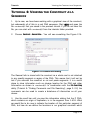
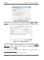
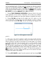
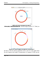
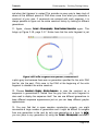
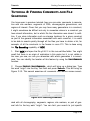
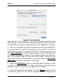
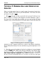
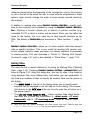
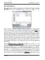
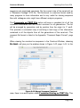
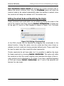
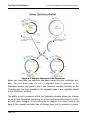
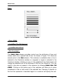
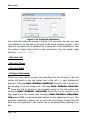
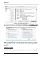
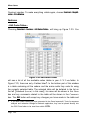
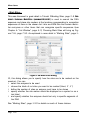
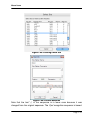
1
GENE
CONSTRUCTION
®
KIT 3.5
Tutorials &
User Manual
from Textco BioSoftware, Inc.
February 2012, Second Edition
Gene Construction Kit® 3.5 Manual is Copyright © Textco
BioSoftware, Inc. 2003-2012. All rights reserved.
Textco BioSoftware, Inc.
27 Gilson Road
West Lebanon,
New Hampshire 03784
U.S.A.
voice/FAX: 603-643-1471
email: [email protected]
URL: http://www.textco.com/
TABLE OF CONTENTS
Overview
Installing Gene Construction Kit® . . . . . . . . . . . . . . . . . . . . . . . . . . . . . 1-1
Overview . . . . . . . . . . . . . . . . . . . . . . . . . . . . . . . . . . . . . . . . . . . . . . . . . . 1-3
Running The Program . . . . . . . . . . . . . . . . . . . . . . . . . . . . . . . . . . . . . . . 1-4
Tutorials
Working with Constructs . . . . . . . . . . . . . . . . . . . . . . . . . . . . . . . . . . . . . . 2-2
Marking Sites. . . . . . . . . . . . . . . . . . . . . . . . . . . . . . . . . . . . . . . . . . . . . . . 2-8
Marking Open Reading Frames . . . . . . . . . . . . . . . . . . . . . . . . . . . . . . . 2-11
Viewing the Construct as a Sequence . . . . . . . . . . . . . . . . . . . . . . . . . . 2-15
Modifying the Construct Appearance. . . . . . . . . . . . . . . . . . . . . . . . . . . 2-20
Cloning a DNA Segment and Silent Mutations . . . . . . . . . . . . . . . . . . . 2-24
Chronography – Tracking Cloning History . . . . . . . . . . . . . . . . . . . . . . . 2-31
Finding Comments and File Searching . . . . . . . . . . . . . . . . . . . . . . . . . 2-39
Running Gels and Orientation Analysis . . . . . . . . . . . . . . . . . . . . . . . . . 2-46
Making Illustrations. . . . . . . . . . . . . . . . . . . . . . . . . . . . . . . . . . . . . . . . . 2-51
Working With Generic Constructs . . . . . . . . . . . . . . . . . . . . . . . . . . . . . 2-57
Importing and Exporting Sequences and Other Information . . . . . . . . 2-61
Importing GenBank Sequence Files Using Deluxe Importing . . . . . . . 2-65
Searching and Retrieving Sequence Files from GenBank . . . . . . . . . . 2-68
Translating Across Introns . . . . . . . . . . . . . . . . . . . . . . . . . . . . . . . . . . . 2-71
PCR Analysis . . . . . . . . . . . . . . . . . . . . . . . . . . . . . . . . . . . . . . . . . . . . . . 2-75
Shotgun Cloning . . . . . . . . . . . . . . . . . . . . . . . . . . . . . . . . . . . . . . . . . . . 2-79
Database Searching . . . . . . . . . . . . . . . . . . . . . . . . . . . . . . . . . . . . . . . . 2-82
Construct Window
Overview . . . . . . . . . . . . . . . . . . . . . . . . . . . . . . . . . . . . . . . . . . . . . . . . . . 3-1
Some Important Definitions . . . . . . . . . . . . . . . . . . . . . . . . . . . . . . . . . . 3-2
Selecting Segments . . . . . . . . . . . . . . . . . . . . . . . . . . . . . . . . . . . . . . . . . 3-3
Changing the Construct Display . . . . . . . . . . . . . . . . . . . . . . . . . . . . . . . 3-3
Regions of Interest and Translating DNA . . . . . . . . . . . . . . . . . . . . . . . . 3-5
Attaching Comments to Objects in Construct Window . . . . . . . . . . . . . 3-6
Marking Sites . . . . . . . . . . . . . . . . . . . . . . . . . . . . . . . . . . . . . . . . . . . . . 3-10
Site Markers . . . . . . . . . . . . . . . . . . . . . . . . . . . . . . . . . . . . . . . . . . . . . . 3-12
page 1
TABLE OF CONTENTS
Listing Sites . . . . . . . . . . . . . . . . . . . . . . . . . . . . . . . . . . . . . . . . . . . . . . . 3-15
Viewing the Construct as a Sequence . . . . . . . . . . . . . . . . . . . . . . . . . . 3-18
Formatting A Sequence Listing . . . . . . . . . . . . . . . . . . . . . . . . . . . . . . . 3-18
Inserting New Nucleotides by Typing . . . . . . . . . . . . . . . . . . . . . . . . . . . 3-21
Searching Comments . . . . . . . . . . . . . . . . . . . . . . . . . . . . . . . . . . . . . . . 3-22
Finding a Sequence . . . . . . . . . . . . . . . . . . . . . . . . . . . . . . . . . . . . . . . . 3-23
Cutting, Copying, and Pasting Segments . . . . . . . . . . . . . . . . . . . . . . . 3-24
Silent Mutations . . . . . . . . . . . . . . . . . . . . . . . . . . . . . . . . . . . . . . . . . . . 3-28
Chronography - Tracking Construct History . . . . . . . . . . . . . . . . . . . . . .3-32
Finding Open Reading Frames . . . . . . . . . . . . . . . . . . . . . . . . . . . . . . . . 3-36
Importing Sequences Into GCK . . . . . . . . . . . . . . . . . . . . . . . . . . . . . . . 3-38
Exporting Data From GCK . . . . . . . . . . . . . . . . . . . . . . . . . . . . . . . . . . . 3-41
Magnification and Construct Scale . . . . . . . . . . . . . . . . . . . . . . . . . . . .3-44
Editing Construct Ends and Redefining the Origin . . . . . . . . . . . . . . . . 3-45
List Window
Opening List Files . . . . . . . . . . . . . . . . . . . . . . . . . . . . . . . . . . . . . . . . . . . 4-2
The List Window . . . . . . . . . . . . . . . . . . . . . . . . . . . . . . . . . . . . . . . . . . . . 4-2
New List Entries . . . . . . . . . . . . . . . . . . . . . . . . . . . . . . . . . . . . . . . . . . . . 4-3
Defining a Cut Site . . . . . . . . . . . . . . . . . . . . . . . . . . . . . . . . . . . . . . . . . . 4-4
Creating New Lists . . . . . . . . . . . . . . . . . . . . . . . . . . . . . . . . . . . . . . . . . . 4-5
Alphabetical Lists . . . . . . . . . . . . . . . . . . . . . . . . . . . . . . . . . . . . . . . . . . . 4-5
Exporting Lists . . . . . . . . . . . . . . . . . . . . . . . . . . . . . . . . . . . . . . . . . . . . . . 4-6
Gel Window
Legend . . . . . . . . . . . . . . . . . . . . . . . . . . . . . . . . . . . . . . . . . . . . . . . . . . . . 5-2
Threshold . . . . . . . . . . . . . . . . . . . . . . . . . . . . . . . . . . . . . . . . . . . . . . . . . . 5-2
Viewing a Fragment Size Table . . . . . . . . . . . . . . . . . . . . . . . . . . . . . . . . 5-3
Creating and Rearranging Gel Lanes . . . . . . . . . . . . . . . . . . . . . . . . . . . 5-4
Partial Digests . . . . . . . . . . . . . . . . . . . . . . . . . . . . . . . . . . . . . . . . . . . . . . 5-4
Exporting Gels . . . . . . . . . . . . . . . . . . . . . . . . . . . . . . . . . . . . . . . . . . . . . . 5-5
The Illustration Window
page 2
TABLE OF CONTENTS
Selection vs. Targeting . . . . . . . . . . . . . . . . . . . . . . . . . . . . . . . . . . . . . . . 6-1
Using the Illustration Window . . . . . . . . . . . . . . . . . . . . . . . . . . . . . . . . . 6-2
Tracking Complex Construction Projects . . . . . . . . . . . . . . . . . . . . . . . . . 6-5
Changing Magnification . . . . . . . . . . . . . . . . . . . . . . . . . . . . . . . . . . . . . . 6-7
Exporting Illustrations . . . . . . . . . . . . . . . . . . . . . . . . . . . . . . . . . . . . . . . . 6-8
Menu Items
File Menu . . . . . . . . . . . . . . . . . . . . . . . . . . . . . . . . . . . . . . . . . . . . . . . . . . 7-1
Edit Menu . . . . . . . . . . . . . . . . . . . . . . . . . . . . . . . . . . . . . . . . . . . . . . . . 7-11
Window Menu . . . . . . . . . . . . . . . . . . . . . . . . . . . . . . . . . . . . . . . . . . . . . 7-16
Format Menu . . . . . . . . . . . . . . . . . . . . . . . . . . . . . . . . . . . . . . . . . . . . . . 7-17
Tools Menu . . . . . . . . . . . . . . . . . . . . . . . . . . . . . . . . . . . . . . . . . . . . . . . 7-35
Construct Menu . . . . . . . . . . . . . . . . . . . . . . . . . . . . . . . . . . . . . . . . . . . 7-42
Gel Menu . . . . . . . . . . . . . . . . . . . . . . . . . . . . . . . . . . . . . . . . . . . . . . . . . 7-71
Illustration Menu . . . . . . . . . . . . . . . . . . . . . . . . . . . . . . . . . . . . . . . . . . . 7-73
List Menu . . . . . . . . . . . . . . . . . . . . . . . . . . . . . . . . . . . . . . . . . . . . . . . . . 7-77
Appendix
Legal Nucleotide Characters . . . . . . . . . . . . . . . . . . . . . . . . . . . . . . . . . . 8-1
Import File Formats . . . . . . . . . . . . . . . . . . . . . . . . . . . . . . . . . . . . . . . . . 8-2
Comment Export Format . . . . . . . . . . . . . . . . . . . . . . . . . . . . . . . . . . . . . 8-4
GCK Acknowledgements . . . . . . . . . . . . . . . . . . . . . . . . . . . . . . . . . . . . . 8-5
Textco BioSoftware, Inc. License Agreement . . . . . . . . . . . . . . . . . . . . . 8-8
Inde
page 3
TABLE OF CONTENTS
page 4
TABLE OF CONTENTS
page 5
TABLE OF CONTENTS
page 6
Overview
Installing Gene Construction Kit®
Chapter 1
Overview
Installing Gene Construction Kit®
The initial GCK installation places all needed files in a single folder. The
installed files include the most recent restriction enzyme database, tutorial,
sample, and help files, and a vector database. All the files need to be
installed on your hard disk from this CD.
On the Macintosh
Here is the complete step-by-step installation process:
1. Insert the GCK Installer CD and locate the GCK folder.
2. Drag this folder to your hard disk. Although not strictly necessary, it is best
to drag it into the Applications folder.
3. With the CD still in the computer, start up the GCK application you just
installed. Enter the personalization information. The first time you run the software GCK needs to verify itself by checking the CD. For subsequent
launches, this is not necessary.
4.You are finished installing the software. You can now remove the CD from
your computer. Please read the notes below and enjoy using Gene Construction Kit.
On Windows
1. Insert the CD into the drive of the computer on which you wish to run
Gene Construction Kit.
Page 1-1
Overview
Installing Gene Construction Kit®
2. From this installation CD, double-click on the application file titled
Setup.exe to launch the installer program. Click “Yes” or “Next” to keep the
defaults and install the application into the Program Files folder of your hard
drive.
3. With the CD still in the computer, start up the GCK application by choosing Start > Program Files > Gene Construction Kit. Enter the personalization information.
The first time you run the software GCK needs to verify itself by checking the
CD. For subsequent launches, this is not necessary.
4. You are finished installing the software. You can now remove the CD
from your computer. Please read the notes below and enjoy using Gene Construction Kit.
A few notes about the installation
•
•
•
On the Mac, it is important to drag the entire folder from the CD to ensure
that the application will run properly. Dragging just the application from the
CD to your hard disk will not work. If you have a previous version of GCK
and have files that you would like to keep with the application, you can
place them into the new GCK folder once you have dragged it from the
CD.
On both Mac and Windows, the first time you run the new GCK, you will
be asked to insert the original CD (unless it is already in the CD drive).
This is the only time you will need to do this unless you reformat your
hard disk.
To personalize your installation, access the License Info panel by selecting Help > License Info... (Windows), or Gene Construction Kit > License
Info... (Mac), then click the Personalize... button. The License Info panel
also displays the version and serial number of the GCK license installed,
and offers a convenient way for Textco BioSoftware’s support team to
help a user ‘Activate’ an installation should the need arise (i.e. hard drive
crash, newer OS, etc.). Using unique activation codes, the Textco BioSoftware support team can reconfigure or change the license type, serial
number or expiration date accordingly.
Updating Gene Construction Kit
Updates are available for GCK from our web site as they are needed. You
Page 1-2
Overview
Overview
must have at least version 3.5.0 to update through the web. Check
<http://www.textco.com/support.php> to see if there is a newer
version. To run the newer version of the application, download it from the
web site, remove the previous version of the application, and put the new
version into the GCK folder on your hard disk. After checking that it works,
discard the older version of GCK. Up to date instructions are always available at the web site.
On the GCK CD, we have included a demo version of Gene Inspector®.
This is Textco’s DNA and protein analysis program that complements GCK.
You can install the demo using the installer provided in the Gene Inspector
Demo folder.
Please call us if you have any questions or problems.
We hope you enjoy your new software.
Overview
The Gene Construction Kit® has been designed to facilitate handling DNA in
an innovative and intuitive way. Over a decade of development by a team
consisting of molecular biologists and programmers has lead to an interface
and a set of functions in Gene Construction Kit (GCK) that will significantly
enhance laboratory productivity and minimize experimental design errors.
The backbone of the program is the construct, which represents a DNA
sequence and all associated sites, regions of interest, segments, comments,
and history. The construct can be manipulated and analyzed using four types
of windows. Each GCK window visible on the screen corresponds to a file on
the disk. The name of the window is the name of the file. There are four
kinds of GCK windows: Construct, List, Gel, and Illustration. These are
described briefly below and in their own chapters in this manual.
All manipulations of the actual DNA are carried out on the construct within the
Construct Window. Restriction enzyme and other sites can be marked,
regions of interest can be defined, silent mutations generated, PCR products
Page 1-3
Overview
Running The Program
generated, and the appearance of the construct and its annotations can be
edited within the Construct Window. The construct can be displayed as linear
or circular and either graphically or as a formatted DNA and protein sequence
listing. Construct Window details are discussed in Chapter 3, page 3-1.
The List Window is used to create, maintain and edit lists of sequences. The
list may contain restriction enzyme recognition sequences, protein binding
sites, linkers, promoters, etc. Cut sites can be defined for sequences in the
list and comments can be associated with any item in the list. When the list
items are used to mark sites in the construct, the comments remain associated with each site that is marked on the construct. More information about
the list window is given in Chapter 4, page 4-1.
The Gel Window is used to simulate gel electrophoresis patterns. Any number
of digests can be displayed in the Gel Window. Partial digests can be viewed
and lanes can be cut and pasted within and between gel windows. In addition
to a graphical view of the gel, the digests can be viewed as tables of fragment size information. The Gel Window is discussed in Chapter 5, page 5-1.
The Illustration Window is used to create documents for presentation or publication, and can also be used to track complex construction projects. Graphics and text from Construct, List, and Gel Windows can be pasted into an
Illustration Window and legends can be automatically generated. Graphics
and text generated in other programs can be copied and then pasted into a
GCK Illustration Window. Once pasted into an Illustration Window, constructs
are separate from their original file, but can still be edited using all the tools
normally available in the Construct Window. The Illustration Window also contains a comprehensive set of graphical drawing tools for enhancing illustrations. For more information on the Illustration Window see Chapter 6, page 61.
Running The Program
GCK is a comprehensive program with many capabilities. The first time you
run it, the possibilities might seem so extensive that you are not sure of what
to do first. To provide you with an overview of the capabilities and to give you
Page 1-4
Overview
Running The Program
a feel for how the program actually works, you should go through the various
tutorials in Chapter 2. If you read nothing else in this manual, you should
read and carry out the tutorials. These tutorials are designed to help orient
you and will greatly facilitate your understanding of the program and its features, while pointing out features you may not think to look for. The time you
spend in the tutorials will be repaid many times over in the future as you use
GCK.
GCK has a straightforward and intuitive interface with extensive “undo” capabilities. It has what is called revealed complexity - you can see as much
detail as you choose. You should not hesitate to try things for yourself. Select
menu options, tool palettes, etc. to see what they do. The Format Menu, in particular, is available from many places within the program and will be useful in
ways you might not expect. Besides the tutorials, one of the best ways to
learn the capabilities of the Gene Construction Kit is to try new menu options
or tools for yourself.
Page 1-5
Overview
Page 1-6
Running The Program
Tutorials
Chapter 2
Tutorials
This chapter contains a number of tutorials that introduce you to the Gene
Construction Kit®. You should do as many of the tutorials as you can
because they provide an overview of how the program works. Doing the tutorials now will save you many hours in the future. The Gene Construction Kit
has a number of unique features you might not have seen in any other application – the tutorials provide a way for you to learn about these unique capabilities.
In many locations in this chapter and throughout the manual you will be
asked to select items in menus. To make your choices as clear as possible,
all menu selections are indicated as hierarchical choices using this Menu font,
such as Edit > Select All. This particular case means to locate the Edit menu and
then choose Select All under the Edit menu.
Page 2-1
Tutorials
Working with Constructs
TUTORIAL 1: WORKING WITH CONSTRUCTS
Perhaps the most important window in GCK is the Construct Window. This is
the place where you will do the majority of your cloning manipulations and
can precisely define how your construct will look. In this tutorial you will learn
how to modify the appearance of constructs. Tutorial 2: “Marking Sites”, page
2-8 shows how to mark restriction sites and other features in your construct.
Tutorial 7: “Chronography – Tracking Cloning History”, page 2-31, shows how
GCK can automatically keep track of construct history for you. Tutorial 4:
“Viewing the Construct as a Sequence”, page 2-15 discusses the sequence
view of a construct.
1.
Start GCK.
2. Open the file called BluescriptK S+ in the tutorialfiles folder by choosing
This will bring up Figure 2.1. This folder should be in the GCK
File > Open….
Figure 2.1: Opening a file
folder that was created when the program was installed. The buttons on the
Page 2-2
Tutorials
Working with Constructs
bottom let you choose to have listed different types of files in the list on the
left. Since we are opening a construct file, leave the radio button set on Construct. When you open other kinds of GCK files, the buttons will be useful to
you. Select the BluescriptK S+ file and press the Open button. You will see
Figure 2.2.
Figure 2.2: Bluescript KS+
3. This construct has a number of segments, or sections, of DNA indicated
in different colors and patterns. The title of the file is indicated in the title bar
at the top of the window. In the lower left corner of the Construct window is
an indicator of the location of the current insertion point. The insertion point is
where new sequence would be placed into the current construct by typing or
pasting, between nucleotides 625 and 626 in this window (you might have a
different location in your file). Clicking with the mouse anyplace along the
DNA will place the insertion point at the closest boundary between two segments.
4. Double-click on the red segment of DNA to select it. This is similar to
selections made in standard text editing programs, where double-clicking
selects a word. This will highlight the red segment as shown in Figure 2.3,
page 2-4. Note how the indicator in the bottom left corner now shows the
Page 2-3
Tutorials
Working with Constructs
Figure 2.3: Selected Segment
range of nucleotides selected. The range is always shown in the clockwise
orientation (or from left to right for linear constructs). You should see 792625 selected. The origin (top of construct) is defined as position#1. Clicking
on this popup menu will also allow you to show the position of the cursor as
you move it over the DNA, or the size of the selected DNA segment.
5. Once an object (like a DNA segment) is selected, you can modify it.
Choose Format > Lines > and choose the second line down to change the width
of the selected DNA segment to 2 pixels. In the Lines menu, you can set the
width using the line thicknesses shown in the menu, or you can choose Format
> Lines > Pick a Width… to type in your own thickness. Using the Format menu, you
can change the appearance of the selected object. For now, do not change
anything else but feel free to explore the Format menu on your own when you
finish this tutorial.
6. This vector has T3 and T7 promoters and a polycloning site that we want
to indicate. The promoters are shown in green and the polycloning site is a
striped blue. Let’s add directionality to the promoters. Before you can add
arrowheads to any segment of DNA it must first be selected. The promoter
segments are rather small and might be difficult to select at this magnification.
So click the mouse on one of the green segments (between the blue and red
segments) to place the insertion point near what we are interested in and
then choose Construct > Magnification > Zoom In to enlarge the view of the conPage 2-4
Tutorials
Working with Constructs
struct. Zoom In again and then select the top green segment by double-clicking. You will see Figure 2.4, page 2-5. Nucleotides 626-645 will be
Figure 2.4: Magnified View
selected.
7. Choose Construct > Get Info… to see the name of the segment and any comments associated with that segment. This is the T7 promoter as shown in
Figure 2.5. Every segment of DNA can have a name and comments associ-
Figure 2.5: Segment Get Info Box
Page 2-5
Tutorials
Working with Constructs
ated with it. These comments can be used to store important information
about the construct and can be searched using the Search Files capability of
GCK (Tutorial 8: “Finding Comments and File Searching”, page 2-39). We
will talk more about this dialog box later (Tutorial 7: “Chronography – Tracking Cloning History”, page 2-31). For now just press the Cancel button –
you don’t want to make any changes.
8. You should still have the T7 promoter selected as shown in Figure 2.4,
page 2-5. If you do not, then select it again by double-clicking on the segment. First, let’s change the line thickness by choosing Format > Lines > and
choose the third line down to change the width of the selected DNA segment
to 3 pixels. Next add an arrowhead pointing in the clockwise direction by
choosing Format > Lines > and choosing the rightward pointing arrow in the second section of the Lines menu.
9. The last step is to adjust the arrowhead size. This is done by choosing
You will see Figure 2.6. Click and drag the
Format > Lines > Size Arrowhead….
Figure 2.6: Size Arrowhead
mouse in the dialog box to resize the arrowhead to be approximately what is
shown in this figure. Click OK.
10. We now need to adjust the T3 promoter segment to point in the counterclockwise direction. This can be done by following the same steps we just did
for the T7 promoter. Briefly, do the following: Select the lower green segment
(the T3 promoter) by double-clicking on it. If you cannot see this segment in
the window, use the scroll-bars to bring it into view. Choose Format > Lines > and
select the third line down to change thickness, choose Format > Lines > and
select the leftward pointing arrow. This will add an arrowhead that is the
same size as the last arrowhead created so you should have symmetrical
Page 2-6
Tutorials
Working with Constructs
arrowheads.
11. Finally, we want to see the whole construct again, so choose Construct >
Magnification > Fit to Window. This will produce Figure 2.7, page 2-7. We have
Figure 2.7: Modified Bluescript KS+
now formatted the segments of this construct to meet our needs.
12. You now need to save the construct under a new name. You might first
want to create a folder on your desktop to hold the different tutorial files you
will be creating in this and in subsequent tutorials. Having a single folder will
make it easier to find the tutorial files you create as you need them in later
tutorials. Choose File > Save As…, name the file construct#1, and save it in your
own folder – please do not replace the tutorial files provided because others
might want to use them later on. Make sure you know where you are saving
this file. You will need it again later.
You can quit now, or continue on to Tutorial 2: “Marking Sites”, page 2-8. If
you plan on continuing, you can leave the file you just created, construct#1,
open. If not, close this file.
Page 2-7
Tutorials
Marking Sites
TUTORIAL 2: MARKING SITES
1. Start GCK and open the file construct#1, which you created in the first
tutorial. If you do not have this file, you can start with construct#1 from the
tutorialfiles folder provided.
2. The next thing to do is to mark restriction enzyme sites that are located
only in the polycloning region and nowhere else. To begin, double-click on
the polycloning segment which has a blue lined pattern and is located at
about 3 o’clock. You should see the segment become selected.
3. Choose Construct > Features > Mark Sites…. You will see Figure 2.8. This dialog
Figure 2.8: Mark Restriction Sites
is discussed more fully in “Marking Sites”, page 3-10. For now, make sure
that the commercial (no isoschiz) list shows in the popup menu at the top of
the dialog. A list of enzymes will appear in the left scrollable area. Press the
Add All -> button to add all the enzymes in this list to the right side list of
Enzymes to mark.
4. In the middle section on the left, set the numbers to match that in the figure so you will be specifying enzymes that cut more than 0 times but less
than 2 times – i.e. unique cutters.
Page 2-8
Tutorials
Marking Sites
5. Finally, choose the middle radio button on the bottom left of the dialog
box to specify that you want to see those enzymes which cut exclusively
within the selected segment of DNA. Now press the OK button to mark the
sites.
6. You will see the construct labeled as shown in Figure 2.9A. Note that all
A
B
C
Figure 2.9: Marked Sites
the sites are crowded together. While all the newly marked sites are still
selected choose Format > Site Markers > Automatic Arrangement. This will rearrange
the site markers so that they do not overlap resulting in something that looks
like Figure 2.9B.
7. As was the case for a selected segment of DNA, when a site marker is
selected, you have access to items in the Format menu to change the display
of the site marker. Now shift-click on the BamHI site to deselect it (all the
other sites remain selected). Select the Format > Site Markers > Show Site As Symbol
to change all of the sites to symbols except the BamHI site. Click on the
BamHI marker and use the Format > Style menu to make the text bold; use the
Format > Size menu to make the text 10 point. You should end up with somePage 2-9
Tutorials
Marking Sites
thing that looks like Figure 2.9C.
8. While the BamHI site marker is still selected, choose Construct > Get Info… or
press command-I (Mac) or ctrl-I (Windows). This will provide you with the information shown in Figure 2.10. If you wanted to, you could actually change the
Figure 2.10: Site Marker Get Info Dialog
name of the enzyme (not a good idea) or enter comments in the comments
text box. The horizontally scrollable area in the lower part of the dialog box
indicates the actual sequence at that location. The dotted red rectangle indicates the recognition sequence for the restriction enzyme and the two arrows
indicate the actual cut sites for the enzyme. You can change the cut site by
clicking on an arrow and dragging it. Press Cancel to close this dialog without saving any changes.
9. Choose File > Save As…, name the file construct#2, and save it in your own
folder – please do not replace the tutorial files provided because others might
want to use them later. You will need it again in the next tutorial.
You can quit now, or continue on to Tutorial 3: “Marking Open Reading
Frames”, page 2-11. If you plan on continuing, you can leave the file you just
created, construct#2, open. If not, close this file.
Page 2-10
Tutorials
Marking Open Reading Frames
TUTORIAL 3: MARKING OPEN READING FRAMES
1. Start GCK and open the construct file you created in the last tutorial,
construct#2. If you do not have this file, you can start with construct#2 from
the tutorialfiles folder provided.
2. You will finish annotating this construct in this tutorial and learn how to
define open reading frames (ORFs). First, choose Construct > Display > Show Construct Title which will place the title of the construct and the length of the construct into the center of the window.
3. Now choose Construct > Features > Find Open Reading Frames…. You will see the
dialog shown in Figure 2.11. This dialog gives you complete information about
Figure 2.11: Finding Open Reading Frames
how the program will look for ORFs. The minimum ORF length text field tells
the program to only display those ORFs containing 100 or more amino acids.
As explained in “Finding Open Reading Frames”, page 3-36, you can select
the codon table to be used and specify whether to search one or both strands
of DNA. If you are looking for ORFs in exons you might want to turn off the
Start at ‘ATG’ check box - the program will then find any open reading
frame (not just those starting with ATG). After you’ve adjusted the dialog to
look like the one shown here, press the OK button to find the ORFs.
4. After running the ORF search you will see two new objects in the construct window: arrows representing the two different ORFs found by this
Page 2-11
Tutorials
Marking Open Reading Frames
search, as shown in Figure 2.12. Both ORFs are highlighted. These ORFs
Figure 2.12: ORFs are Marked
represent regions of interest, or regions. In addition to site markers and DNA
segments, regions are a third kind of object that can appear in the construct
window. Regions can be formatted using the Format > Regions > submenu.
5. Click somewhere in the window to deselect the regions just created. Now
click once on the region on the right side that overlaps the polycloning site.
Now choose Construct > Get Info… to bring up Figure 2.13, page 2-13. This dialog
contains information about the selected region. You can change the direction
of the region by clicking the Top Strand or Bottom Strand radio buttons.
Changing the numbers in the First Nucleotide or Last Nucleotide box
will change the length of the region. The Protein Sequence check box
determines if the region is to be translated or not when viewed as an actual
sequence (see Tutorial 4: “Viewing the Construct as a Sequence”, page 2-15
for more information).
6. This region is the beta-galactosidase region, so type “beta-galactosidase”
into the Region Name text box. You can also enter comments into the Region
Comments text box. Both the name and the comments can be searched by
GCK later (Tutorial 8: “Finding Comments and File Searching”, page 2-39).
In this case it might be reasonable to enter some comments about this vector
Page 2-12
Tutorials
Marking Open Reading Frames
Figure 2.13: Region Get Info Dialog
and how the polycloning site disrupts the β-gal coding region. Click OK to
close this dialog box.
7. With the region still selected, choose Format > Regions > Show Region Names.
This will display the region name in the construct window. You can select this
name and alter the appearance of the text by using appropriate items under
the Format menu. The region name text can be dragged around the construct
window. When the region name text is selected, it is highlighted along with
the region itself, making it clear which region is connected with the text.
8. Now select the left region by clicking on it once with the mouse. Choose
Change the name of this region to “ampicillin resistance”
and put in comments indicating that the gene product is “beta-lactamase”.
Click OK.
Construct > Get Info….
9. Note that when you have a region selected, you have access to many
items in the Format menu. This will allow you to change the appearance of the
arrow in the construct and even change directions by using the Format > Lines…
menu. This would be equivalent to changing the protein direction in Figure
2.13.
10. Choose File > Save As…, name the file construct#3, and save it in your own
folder – please do not replace the tutorial files provided because others might
want to use them later. You will need it again in the next tutorial.
Page 2-13
Tutorials
Marking Open Reading Frames
You can quit now, or continue on to Tutorial 4: “Viewing the Construct as a
Sequence”, page 2-15. If you plan on continuing, you can leave the file you
just created, construct#3, open. If not, close this file.
Page 2-14
Tutorials
Viewing the Construct as a Sequence
TUTORIAL 4: VIEWING THE CONSTRUCT AS A
SEQUENCE
1. Up to now, we have been working with a graphical view of the construct,
but underneath all of this is a real DNA sequence. Start GCK and open the
file construct#3 that you saved in the previous tutorial. If you do not have this
file, you can start with construct#3 from the tutorials folder provided.
2. Choose Construct > General Info…. You will see something like Figure 2.14.
Figure 2.14: General Info Dialog
The General Info is stored with the construct as a whole and is not attached
to any specific segment or region of the DNA. This means that it will not be
lost if you reformat the construct or cut and paste segments. It is a useful
place to store information such as storage location for the DNA and other
information as shown in construct#3. In combination with the File Searching
ability (Tutorial 8: “Finding Comments and File Searching”, page 2-39), the
comments can be used to create a database of information on all your
clones.
3. Use the scroll bar until you see the information stating that the f1 DNA,
which contains an origin of replication, is in the segment from 3-458. What
we would like to do now is indicate the location of this particular segment of
DNA, but how do we define the locations in our graphical construct which
Page 2-15
Tutorials
Viewing the Construct as a Sequence
does not have any markers at those locations? The answer is to view the
construct as a sequence rather than graphically. Close the General Info window and then choose Construct > Display > Display Sequence. This will bring up Figure 2.15. If your display does not look like this figure, then scroll the
Figure 2.15: Viewing the Construct as Sequence
sequence all the way to the top of the window. Notice the correspondence
between the graphical view and the sequence view. Colors are maintained,
sites are marked, and regions are indicated. However, since we specified that
the regions we marked are protein regions (Figure 2.13, page 2-13), the
translated peptide is displayed below the actual DNA sequence. The small triangles adjacent to the amino acid line numbers indicate the direction of translation.
4. Before we can mark the f1 origin of replication, we need to be able to
identify the nucleotides to be marked. Let’s add position indicators by choosing Construct > Display > Show Positions. Remember how double-clicking on a segment in the graphical view of the construct selected that particular segment?
This works the same way in the sequence view. So double-clicking anywhere
in the DNA sequence will select that entire segment. Try this by double-clicking anywhere in the sequence to get a feel for how segments are defined.
You will notice that segment boundaries can be site markers or changes in
color or text characteristics.
Page 2-16
Tutorials
Viewing the Construct as a Sequence
5. With the insertion point (mouse cursor) anywhere in the DNA sequence,
choose Edit > Select All (command-A, Mac or ctrl-A, Windows). This will select all
of the DNA sequence. Now choose Format > Grouping > Group by Tens. This will
arrange the sequence to be displayed in groups of tens. Note that there is an
option in the Format > Grouping menu to define your own group size. This can be
useful, for example, if you are working with something like an octamer repeat.
You can define a groups size of 8 to display this repeat easily.
6. Grouping by ten is good for viewing the sequence and identifying specific
locations, but does not look right for viewing those parts of the sequence that
correspond to translated regions of the DNA. We need to group the translated
regions into groups of three corresponding to the codons. This can be done in
two ways. You could select the DNA corresponding to the peptide by clicking
and dragging the mouse over the correct region of DNA. There is an easier
way to do this, however, by just double-clicking on the amino acid sequence.
This is a built-in feature of GCK to make it easier to select DNA segments
that correspond to regions. Double-clicking on any region will select the corresponding segment of DNA. So double-click on the amino acid sequence
corresponding to the β-galactosidase gene (it ranges from 244-846). Now
choose Format > Grouping > Group by Threes.
7. We now need to indicate our origin of replication. Identifying origins of
replication is something that you might like to do in all of your constructs and
you would like an easy visual method of identifying those regions from
amongst the many that you might end up marking. You can do this by defining a specific color to represent an origin of replication. Choose Format > Color >
Add a Color…. You will see Figure 2.16. Type in “origin of replication” for the
name of the color and then press OK. Choose a color from your computer’s
standard Color Picker. Now you have defined a new color called origin of
replication. This color should now appear in the Format > Color menu. The ability
to define your own color and to name it provides an easy way for you to indicate features of interest such as promoters, enhancers, and other sites on
DNA. If all your constructs are defined using your own “standard” colors, it
will be easy to recognize specific functions of constructs just by observing the
colors.
8. Let’s take advantage of the new color we just created to identify the origin of replication for our construct. Use the mouse to select nucleotides 3
Page 2-17
Tutorials
Viewing the Construct as a Sequence
Figure 2.16: Add a Color Dialog
through 458. You can confirm that you have the correct nucleotides selected
by looking in the lower left corner of the window. Choose Construct > Features >
Make Region…. You will see the dialog shown in Figure 2.17. Make sure you
Figure 2.17: Creating a New Region
type in the correct name and put any comments you have into the comments
area. This is NOT a protein sequence so do not check the Protein
sequence checkbox. Confirm that the first and last nucleotides are 3 and
458, respectively. Press OK.
9. The newly created region will be selecteda so you can now alter its
a.
If it is not selected, then just click on it once to select it.
Page 2-18
Tutorials
Viewing the Construct as a Sequence
appearance. Choose Format > Lines and select the line having an arrowhead at
both ends. This will change the region to have two arrowheads.
10. With the region still selected, choose Format > Color > origin of replication to
change the color of the region to indicate its function.
11. You can also use the Format menu now to change the line thickness and
arrowheads if you so desire. When you are done you should see something
like Figure 2.18, page 2-19. You can now easily recognize the origin of repli-
Figure 2.18: Origin of Replication Indicated
cation by color and can use that region to select the corresponding DNA by
double-clicking on the region.
12. Choose File > Save As…, name the file construct#4, and save it in your own
folder – please do not replace the tutorial files provided because others might
want to use them later. You will need this file in the next tutorial. That tutorial
will explain how to enhance the appearance of your sequence in the construct
window.
You can quit now, or continue on to Tutorial 5: “Modifying the Construct
Appearance”, page 2-20. If you plan on continuing, you can leave the file
you just created, construct#4, open. If not, close this file.
Page 2-19
Tutorials
Modifying the Construct Appearance
TUTORIAL 5: MODIFYING THE CONSTRUCT
APPEARANCE
1. Start GCK and open the file construct#4 that you saved in the previous
tutorial. If you do not have this file, you can start with construct#4 from the
tutorials folder we provided.
2. It is possible to modify the sequence appearance using many of the items
in the Format menu. Select the AT-rich segment from nucleotides 10-33 by
dragging with the mouse. Now Choose Format > Font > Show Fonts > Times (commandT Mac or Ctrl-T Windows) and notice that even though Times is not a monospaced font, GCK still spaces the characters so that each character occupies
the same width along the line. Now choose Format > Style > Bold. The bold characters are wider than the non-bold characters so this part of the sequence
becomes more “spread out”. You can adjust for that by choosing Format > Style
> Condense, which condenses the spacing between characters. You can change
colors, fonts, and styles for any segment of the DNA to help indicate certain
features. Feel free to try some of these on this segment now.
3. Another method can be used to illustrate certain features. This is through
the use of Frames. To see how frames work, select nucleotides 676-699
(they are in the polycloning region). Choose Construct > Features > Make Frame.
This will create a frame around the segment of DNA you selected and will
include the region (amino acid sequence) and site markers. It should look
similar Figure 2.19. The frame is selected (highlighted) and encloses all infor-
Figure 2.19: A Framed Sequence
mation related to that particular segment of DNA.
4. The appearance of the frame can be altered by using items in the Format
menu, as usual. Note that a frame must be selectedb (it must appear highlighted in the window) in order for items in the Format menu to have any effect
on the frame itself. With the frame selected, choose Format > Lines > and choose
Page 2-20
Tutorials
Modifying the Construct Appearance
the second line thickness in the menu (it is two pixels wide). Choose Format >
Color > Yellow, and then choose a fill pattern using Format > Fill. You can try different patterns and colors to see how they look. (If you plan to print the
sequence, remember to use a light color for the fill pattern so that it does not
obscure the text.)
5. Note that the frame encompasses the site markers, the DNA, and the
region. You can limit what is enclosed in the frame by choosing Construct > Features > Set Frame Contents… as shown in Figure 2.20. This dialog allows you to
Figure 2.20: Set Frame Contents
define which items will be enclosed in the frame. Set your dialog box to look
like the one shown here and then press OK.
6. It is somewhat difficult to distinguish between the DNA sequence and the
protein sequence, so let’s change the appearance of the protein sequence.
Click once to select the protein sequence and then choose Format > Font > Show
Fonts > Times, (command-T Mac or Ctrl-T Windows) then Format > Style > Italic. Your
display should now resemble that shown in Figure 2.21, page 2-22. The ability to alter the display of the sequence in so many ways provides a great deal
of flexibility in pointing out specific features of any sequence with which you
are working.
b.
A frame can be selected by option-clicking (on the Mac) on the frame or by choosing
Construct > Select Frame and then clicking on the frame you want to select. For those of
you who are “quick-fingered” you can also select a frame by triple-clicking on the DNA
contained within a frame.
Page 2-21
Tutorials
Modifying the Construct Appearance
Figure 2.21: A Modified Framed Sequence
Construct > Display > Display Graphics. Note that the
7. Choose
new region you
defined as the origin of replication also appears in the graphical display and is
selected as it was in the sequence display. There is a direct correspondence
between the two views of the construct. Changes you make in the graphical
view appear in the sequence view and changes you make in the sequence
view appear in the graphical view. The graphical view just represents an easier way to visualize your construct. For cloning fragments (Tutorial 6: “Cloning
a DNA Segment and Silent Mutations”, page 2-24), this is essential to maintaining an easy to use interface.
8. Click on the BamHI site marker name and then select all site markers by
pressing command-A (Mac)/ctrl-A (Windows) or by choosing Edit > Select All. We
want to change the appearance of all the site markers except for the BamHI
site so we need to deselect the BamHI site while leaving the others selected.
This is done in the standard way of holding down the shift key and clicking on
the BamHI site (this process is called shift-clicking)c. Make sure that you
have all the sites selected with the exception of the BamHI site. Now choose
Format > Site Markers > Show Site As Symbol. You have something resembling Figure
2.9, page 2-9C. Note that you might not have the same set of symbols as
shown in this figure.
9. Choose File > Save As…, name the file construct#5, and save it in your own
folder – please do not replace the tutorial files provided because others might
want to use them later. You will need it again in the next tutorial. That tutorial
will explain how to use your new vector as the recipient of foreign DNA.
You can quit now, or continue on to Tutorial 6: “Cloning a DNA Segment and
Silent Mutations”, page 2-24. If you plan on continuing, you can leave the file
c.
Note that you could accomplish the same result by clicking on a single site marker and
then holding down the shift key and clicking on every other site marker except the BamHI
site.
Page 2-22
Tutorials
Modifying the Construct Appearance
you just created, construct#5, open. If not, close this file.
Page 2-23
Tutorials
Cloning a DNA Segment and Silent Mutations
TUTORIAL 6: CLONING A DNA SEGMENT AND
SILENT MUTATIONS
Our goal in this tutorial will be to take the construct we have been working
with in previous tutorials and use it to receive a new segment of DNA. In
doing this you will learn about copying and pasting segments of DNA and
how to keep track of the history of your construct.
1. Start GCK and open the file construct#5 that you saved in the previous
tutorial. If you do not have this file, you can start with construct#5 from the
tutorials folder provided.
2. Open the file called hsp70 from the tutorials folder. This file contains the
gened we will be using as the source of the fragment being cloned. Notice
that there is a single region indicating the open reading frame. We will be
cloning a segment containing this region into the BamHI site on construct#5.
3. The first thing to do is mark the BamHI sites in hsp70. Make sure that
the window with hsp70 is in front and then choose Construct > Features > Mark Sites
[or press command-M (Mac)/ctrl-M (Windows)]. Select BamHI in the left hand
list and press the Add -> button to add this enzyme to the Enzymes to mark
list on the right (see Figure 2.8, page 2-8). Select to display new sites as
enzyme names. Press OK to mark the sites. You will see Figure 2.22.
4. To cut out the segment we are interested in we need to address the
problem of the middle BamHI site. In the lab, you could do partial enzyme
digests and obtain the fragment containing the entire coding region by elution
of the fragment from a gel. You can also select this entire region in GCK by
dragging with the mouse from the first (left) BamHI site in the DNA to the
third BamHI site. This fragment can be copied and pasted into the vector. An
alternative is to eliminate the middle BamHI site through a silent mutation.
This mutation will eliminate the BamHI site without interfering with the coding
capacity of the DNA.This is the approach we will take in this tutorial.
d.
Note that this sequence has been derived from an hsp70 gene from Drosophila. The
original sequence has been modified for use in this tutorial. Do not use this sequence as
a real hsp70 sequence.
Page 2-24
Tutorials
Cloning a DNA Segment and Silent Mutations
Figure 2.22: BamHI sites marked on hsp70
5. To make a silent mutation you first need to specify the reading frame to
which you are referring. To do this, select the single region in the hsp70 construct by clicking on it once. Now choose Construct > Features > Remove Sites by
Silent Mutation. You will see the familiar dialog shown in Figure 2.23.Select the
Figure 2.23: Select Enzyme Sites to be Removed
BamHI enzyme in the list on the left and press Add -> to bring it to the right
list of Enzymes to try. Click OK. This will bring up Figure 2.24. Click on the
BamHI name in the list to select it (if there were more than one BamHI site,
you could choose any one or more of them). Now press OK.
6. This will bring up another dialog containing a list of the different possibilities that could be used to remove the BamHI site without altering the coding
information in the DNA. This is shown in Figure 2.25. The original sequence
is shown in the first column and the possible changes are shown in the secPage 2-25
Tutorials
Cloning a DNA Segment and Silent Mutations
Figure 2.24: Selecting the Site To Remove
ond column. The actual changed nucleotide is shown in lower case. Select
the first item in the list (as shown) and then press the OK button.
7. You should now see the hsp70 construct with the middle BamHI site
missing. The actual nucleotide sequence has been changed as specified in
Figure 2.25: Selecting a Silent Mutation
Figure 2.25 with the changed nucleotide being indicated in lower case in the
actual sequence. Choose File > Save As…, name the file hsp70_Bam -, and save it
in your own folder – please do not replace the tutorial files provided because
others might want to use them later. You will need this file again in Tutorial
10: “Making Illustrations”, page 2-51.
8. You are now ready to proceed with the cloning. Click in the DNA segPage 2-26
Tutorials
Cloning a DNA Segment and Silent Mutations
ment at the left BamHI site and drag the mouse cursor to the right until you
have selected all the DNA between the two BamHI sites. The entire segment
should be highlightede.
9. Choose Edit > Copy [or press command-C (Mac)/ctrl-C (Windows)] to copy
this segment to the clipboard. Make the construct#5 window the active window either by clicking in the window with the mouse or by selecting it from
the Window menu.
10. You now need to tell GCK where it is that you would like to paste the
BamHI fragment that is now in the clipboard. To do this you must position the
insertion point at the BamHI site in construct#5. The easiest way to do this is
to click on the site marker text, BamHI. Do this now.
11. You are finally ready to do the actual cloning step. Choose Edit > Paste.
You will be shown a dialog warning youf that the editing operation you are
about to perform (pasting in a fragment) will disrupt a region in the current
construct (the β-galactosidase segment that spans the polycloning site).
Press OK to that dialog. You should see Figure 2.26.
12. Notice in this figure that the coding region from hsp70 is intact and displayed and that the size of the construct shown in the center of the window is
adjusted to reflect the newly inserted fragment. Because a BamHI fragment
was pasted into a BamHI site, both of the BamHI markers have been
restored.
13. Choose File > Save As…, name the file construct#6, and save it in your own
folder – please do not replace the tutorial files provided because others might
want to use them later.
14. Make sure that the blue inserted DNA segment is still selected and then
choose Edit > Special Paste. Since the hsp70 fragment is still on the clipboard (in
e.
f.
You might notice that the selection “pauses” at the location of the former middle BamHI
site. This is because the changed nucleotide has a different color and represents a
“boundary” in the sequence. Selections in the graphical view occur between boundaries.
This alert is shown to warn you of editing operations that you might not be aware of. If
you are pasting into a site that is part of a “feature” in the construct, the pasting operation will disrupt that feature. Therefore it needs to be removed to prevent any confusing
or ambiguous annotations from remaining.
Page 2-27
Tutorials
Cloning a DNA Segment and Silent Mutations
Figure 2.26: Pasted hsp70 Fragment
memory) and you have a segment of DNA selected, pasting will replace the
current selection with what we paste into the construct from the clipboard.
This is just like replacing selected text in a word processor with the contents
of the clipboard. You will see Figure 2.27. Check the Invert Sequence
Figure 2.27: Special Paste
check box and select the Leave Ends Alone radio button. Press. OK. This
Page 2-28
Tutorials
Cloning a DNA Segment and Silent Mutations
will replace the currently selected hsp70 segment with an inverse version of
the same DNA – i.e., it will be flipped over.
15. Choose File > Save As…, name the file construct#7, and save it in your own
folder – please do not replace the tutorial files provided because others might
want to use them later. Since cloning the hsp70 fragment into the BamHI site
has an equally likely chance of occurring in either orientation, these constructs (construct#6 and construct#7) represent two possible outcomes in a
real experiment. You will be able to use these constructs and GCK to predict
gel patterns as detailed in Tutorial 9: “Running Gels and Orientation Analysis”, page 2-46. This demonstrates how easy it is to replace DNAs and to
generate constructs with inserts in either orientation.
16. Before ending this tutorial let’s see how GCK behaves if you try to paste
the BamHI fragment into a site other than a BamHI site. The fragment is still
on the clipboard so all you need to do is define a different insertion point in
the construct to be the target for the pasting operation. To do this, click on
any symbol in the construct to select that site.
17. With the insertion point in the DNA at the selected site, choose Edit > Paste
[command-V (Mac)/ctrl-V (Windows)]. This will bring up a ligation dialog, as
shown in Figure 2.28. Because the fragment ends are incompatible (the
Figure 2.28: Ligation Dialog
selected site in construct, BamHI in clipboard), GCK will not let you paste the
fragments together (ligate them). The sequences shown in this dialog represent the junction shown in the top left corner – in this case, the left DNA
sequence is the result of the selected cut in the vector and the right DNA
segment is the result of the BamHI cut fragment in the clipboard. The arrows
indicate the actual cut sites and illustrate the staggered ends. Note that the
OK button is disabled because the operation is not biologically possible. To
Page 2-29
Tutorials
Cloning a DNA Segment and Silent Mutations
adjust the ends you can drag the arrows with the mouse until you have compatible ends. As soon as the ends are made compatible, the OK button will
become enabled and you will be asked to deal with the “other” junction
between the fragment being pasted and the target sequence. There is a
shortcut to this process using Edit > Special Paste, which is discussed in detail in
“Special Paste…”, page 7-14. For now, press Cancel.
18. Close construct#6 and hsp70_Bam - but do not save any changes. You
may continue with the next tutorial now, or quit the program.
Page 2-30
Tutorials
Chronography – Tracking Cloning History
TUTORIAL 7: CHRONOGRAPHY – TRACKING CLONING HISTORY
One of the most useful features of GCK is called chronography. This feature
allows you to keep track of construct history as well as to store different
views of the same sequence in a single file. It is important to realize that
although you will be seeing different graphics on screen, there is only a single
sequence in each construct file. Chronography allows you the flexibility of displaying the same sequence in a number of ways to bring out key features.
1. Start GCK and open the file called pBR322 in the tutorialfiles folder.
You will see Figure 2.29. This is a fairly standard view of a construct with a
Figure 2.29: pBR322 as Graphic
few restriction sites marked. Note that the SalI site shows both the name and
position for the marker. This can be set in the Format > Site Markers menu (see
“Site Markers”, page 7-23 for more detail). The bottom right corner of the
window shows a scale marker indicating the scale of the drawing. The scale
marker can be shown or hidden by using the Construct > Display > Show/Hide Sites.
2. Choose Construct > Display > Display Sequence to bring up Figure 2.30, page
2-32. As you will see, chronography can be used to store the appearance of
Page 2-31
Tutorials
Chronography – Tracking Cloning History
Figure 2.30: pBR322 as Text
a construct sequence as well as the graphical construct appearance. This
view of the sequence is a simple one, consisting just of the sequence
grouped in tens and a few sites marked.
3. Choose Construct > Display > Display Graphics to return to the graphical view as
in Figure 2.29. All the chronography features are accessible in the Format >
Chronography submenu. Each different view of the construct is referred to as a
different generation. Notice that at the bottom of the Chronography menu are
three different named generations - restrictions sites, regions of interest, and DNA
sources. These are the three different generations present in the pBR322 construct. The generation currently being shown is checked in the menu. Choose
Format > Chronography > Show Previous Generation. This will bring up Figure 2.31,
page 2-33, which is one generation in the past and is referred to as generation#1 (the most recent generation is referred to as generation#0). In this
generation the coding regions are shown along with an origin of replication.
4. Choose Construct > Display > Display Sequence. You will see Figure 2.33 Note
that the sequence is now grouped in threes and the translation of the tetracycline resistance gene is shown. This is not a different sequence - it is just
being displayed differently.
5. Choose Construct > Display > Display Graphics and then choose Format > ChronogPage 2-32
Tutorials
Chronography – Tracking Cloning History
Figure 2.31: pBR322 Generation#1
raphy > Show Previous Generation again to see the most ancient
generation for this
construct. This is Figure 2.32, page 2-33. This generation shows the three
Figure 2.32: pBR322 Generation#2
Page 2-33
Tutorials
Chronography – Tracking Cloning History
different segments that were used to construct the original pBR322 plasmid..
Figure 2.33: pBR322 Generation#1 Sequence
6. Double-click on the blue segment from about 12 o’clock to 5 o’clock to
select that segment. Now choose Construct > Get Info… [or press command-I
(Mac)/ctrl-I (Windows)]. You will see Figure 2.34. This provides information
Figure 2.34: Segment Info
about the source of each DNA segment in the construct. By carefully documenting the sources of each DNA segment, the entire history of a construct
Page 2-34
Tutorials
Chronography – Tracking Cloning History
can be maintained easily. All the comments entered can also be searched
using the File Searching capabilities of GCK (see Tutorial 8: “Finding Comments and File Searching”, page 2-39). Press the Cancel button to return
to the graphical window. Select the entire DNA of the construct by choosing
Edit > Select All [or pressing command-A (Mac)/ctrl-A (Windows)].
7. Choose Format > Chronography > Restriction Sites to bring you back to the most
recent generation of the construct. Remember, this is really just a different
view of the same sequence you have been looking at throughout this tutorial.
8. Choose File > Open and open the file called actin D N A, which is in the
tutorialfiles folder. Double-click on the SalI fragment to select it (Figure
2.35), and then choose Edit > Copy . We will be cloning this fragment into
Figure 2.35: SalI Fragment of Actin DNA
pBR322.
9. Click once in the pBR322 window to make it the active window and then
put the insertion point at the SalI site on the pBR322 DNA. You can do this
either by clicking in the DNA at the location of the SalI marker or by clicking
on the SalI marker itself. Once the insertion point is correctly located, choose
Edit > Paste to paste the actin D N A SalI fragment into the pBR322 at the SalI
site. You will get a warning that you are about to delete a region (the tetracycline region in generation#1 is there, even though you cannot see it - click
OK) and then you will see Figure 2.36, page 2-36. Note that the positions in
the SalI markers have been updated and the size of the construct has been
updated in the center of the window.
10. Choose Edit > Select All to select the entire construct and then choose Format
Page 2-35
Tutorials
Chronography – Tracking Cloning History
Figure 2.36: Actin Fragment into pBR322
> Chronography > Show Previous Generation. This will bring up Figure
2.37. What you
Figure 2.37: Actin Fragment into pBR322, Generation#1
see here is that the previous generation of the actin D N A was copied when
the actin fragment was copied. All generations of a fragment of DNA are copPage 2-36
Tutorials
Chronography – Tracking Cloning History
ied when that fragment is copied. This provides an easy way to keep track of
where all the different pieces of DNA have come from when you assemble a
construct of your own. If comments are entered with each segment, it is
always possible to figure out the entire construct history by looking at different
generations.
11. Again, choose Format > Chronography > Show Previous Generation again. This
brings up Figure 2.38, page 2-37. Notice here that the actin fragment is just
Figure 2.38: Actin Fragment into pBR322, Generation#1
a plain gray line because there was no generation specified for the actin DNA
that far into the past. Click once in the DNA at the beginning of the actin
fragment to deselect the entire construct.
12. Choose Construct > Display > Display Sequence to view the construct as a
sequence in generation#2. Notice how the gray from the actin fragment is
also used to display the sequence itself. You can use different generations to
keep different sequence appearances just as you can keep different graphic
appearances.
13. You may find that in some complex construction projects, you might
accumulate a large number of generations and it might be difficult to navigate
from one generation to the next by only one generation at a time. In GCK,
you can jump to any generation by using the Format > Chronography > submenu.
Page 2-37
Tutorials
Chronography – Tracking Cloning History
There will be a list of all generations at the bottom of this menu. Select the
Regions of Interest generation to go to that generation.
14. Explore the different formats for this generation. Change back to the
graphical view now (Construct > Display > Display Graphics). Try selecting a segment
and then changing the generation for that segment. Note how it is possible to
show different generations for different segments at the same time. This provides a great deal of flexibility for displaying sequences and graphics in
exactly the way you want.
This concludes the tutorial. You will not need the construct you have just
made so close any open files and do not save any changes.
Page 2-38
Tutorials
Finding Comments and File Searching
TUTORIAL 8: FINDING COMMENTS AND FILE
SEARCHING
You have seen in previous tutorials how you can enter comments in association with site markers, segments of DNA, chronographic generations, and
regions of interest. Given that you may have many generations in a construct,
it might sometimes be difficult not only to remember where in a construct you
have stored information, but in which file the information was stored. In addition, if you store information such as storage locations for a given construct
as part of the general information associated with each construct, it is useful
to be able to search quickly through all the files you have to obtain a list, for
example, of all the constructs in the freezer in room 211. This is done using
the File Searching capability of GCK.
1. Start GCK and open the file pBR322 in the tutorialfiles folder. You might
recall that there is an origin of replication in this vector but it is not visible in
the view you see, nor can you remember with which generation it is associated. You can identify the location of this feature by using the Search Comments
function.
2. Choose Construct > Search Comments…, which will bring up a dialog box. Type
the word “origin” into the Key Text field and press Search. This will bring up
Figure 2.39. This search examines all comments and feature names associ-
Figure 2.39: Searching Comments
ated with all chronography, segments, regions, site markers, or part of general info for the key work “origin”. You can limit your search to just specific
Page 2-39
Tutorials
Finding Comments and File Searching
features of the construct by using the checkboxes on the left of the dialog
box.
3. The list that appears in the right of Figure 2.39 contains all those features which have the word “origin” in their names or in their comments. Click
on the word “origin” in the right side list and press Show Info to see the
context of the match. This will bring up Figure 2.40. This is the standard
Figure 2.40: Origin Found
region “get info” box. Note that the word “origin” is highlighted in the Region
Comments field so that you can easily see where it is located. From this dialog, you know that the origin of replication is from nucleotides 2484 to 2723
and can be found as a region in generation#1 (as indicated in the bottom left
corner of the dialog).
4. Searching comments is very useful for looking just within a single construct, but what about looking through all the files on a disk or in a specific
folder or even in a folder on a common file server? This is where the file
searching capability comes in. File Searching allows you to set up sophisticated search criteria and find files on your disk. Choose Tools > Search Files… to
bring up Figure 2.41, page 2-41. In this dialog you enter your search criteria
in the lines at the top of the dialog. For now, we will do a simple search. Just
type in “ampicillin” in the top line. Note that you could just as easily search for
something like “room 211-3B” to find all the constructs stored in the freezer in
room 211, Box 3B - IF you had entered this is the comments. The goal here
is to find all of the files that have comments indicating that they contain the
Page 2-40
Tutorials
Finding Comments and File Searching
Figure 2.41: Searching Files
word “ampicillin” in their comments - this is not the same as searching for the
DNA sequence. If you are careful in entering comments for each of your files,
File Searching can work as a searching tool for your database of constructs.
5. Note that the search query box will display the text you are searching for.
In the Find Match In section of the dialog, you can specify if you want to
search DNA sequences or comments (and titles). Click the radio button that
says Any Comments. You next need to specify the Search Directory. This
is the folder that you wish to search to find matches satisfying the search criteria. If you choose a folder that has other folders inside it, and you want to
search the contents of those folders too, you should check the Check Subdirectories checkbox at the bottom of the dialog.
6. Press the Set Directory button to define the directory (folder) you wish
to search. You will see Figure 2.42. Select the directory containing the files
you wish to search. In this case, just select the G CK 3 folder.
7. Now you are ready to do the search. Press the Search button as shown
in Figure 2.41, page 2-41. You will see a progress indicator informing you of
Page 2-41
Tutorials
Finding Comments and File Searching
Figure 2.42: Set Directory
what is going on and then you will see Figure 2.43. This window shows the
Figure 2.43: Search Results (#1)
Search Query and then lists all of the files that matched the criteria set in the
search. Clicking on a file in the list will allow you to open it. You can also
press the Save List button to create a text file containing all the matches
with your query. This might be useful for generating a list, for example, of all
the constructs containing an ampicillin resistance gene (or those stored in
Page 2-42
Tutorials
Finding Comments and File Searching
room 211 freezer box 3B).
8. Let’s do another search. Choose File > Search Files… again and fill in the
query to match Figure 2.44, page 2-43. In this case, the search is more
Figure 2.44: Searching Files (#2)
complex. We are looking for files that contain ampicillin AND galactosidase
but do NOT contain tetracycline. You can try different combinations of the
and, or, and contains/doesn’t contain popup menus (these are sometimes referred to as Boolean operators) to see how they work by looking at
the search query box at the bottom of the window. Set the query to match the
figure and then press Search.
9. You will see another list similar to the one shown in Figure 2.43, page
2-42. But what if someone did not enter all the comments that should have
been entered? or what if the files were simply imported sequences that had
not been annotated (contained no comments)? If comments were in fact
incomplete, the search results would not be that meaningful (especially if you
are looking for the absence of certain text items like tetracycline). To address
this issue, GCK allows you to search using DNA sequence information
instead of comments. Choose File > Search Files… again. Now select the radio
Page 2-43
Tutorials
Finding Comments and File Searching
Figure 2.45: Searching Files (#3)
button that says DNA Sequence. We want to find constructs that contain an
ampicillin gene and also contain the β-galactosidase gene. You can use a 15
nucleotide sequence to represent each gene. For ampicillin resistance (β-lactamase gene), type in CAACATTTCCGTGTC (you can use lower case too);
for β-galactosidase, type in GCGGATAACAATTTC. Your screen should match
Figure 2.45, page 2-44. Press Search when you are ready.
10. The search results you obtain will be accurate because every file has a
DNA sequence. Thus, if a file has both query sequences, it will appear in the
list. Your search results should be similar to Figure 2.46. In this case pG FP
is selected so the pathname to get to the pG FP construct is shown in the
Search Directory area of this window.
11. This concludes this tutorial. You should close all open windows at this
time (do not save changes to pBR322).
File searching is a very powerful feature. You might elect to have all the constructs at your organization stored on a file server. If users are conscientious
in entering comments, anyone will be able to search the comments of all the
Page 2-44
Tutorials
Finding Comments and File Searching
Figure 2.46: Search Results (#3)
files at the organization and by looking at the comments know who to contact
about obtaining the construct.
Page 2-45
Tutorials
Running Gels and Orientation Analysis
TUTORIAL 9: RUNNING GELS AND ORIENTATION
ANALYSIS
Often in a cloning project there is a need to assay the success of each cloning step. Typically, this is done by gel electrophoresis. This tutorial will teach
you how to run gels in GCK.
1. Start GCK and open the files construct#6 and construct#7 which you created in Tutorial 6: “Cloning a DNA Segment and Silent Mutations”, page 224. If you don’t have these files available, you can use the files that were
installed in your tutorialfiles folder by the same names. Recall that these files
Figure 2.47: Marking sites for orientation analysis
represent an hsp70 fragment cloned into a vector in two different orientations.
We will differentiate between the two orientations by gel electrophoresis in this
tutorial.
2. Bring the construct#6 window to the front by clicking on it or by choosing
it from the Window menu. Make sure nothing is selected in the DNA by clicking once in the DNA – you should see a blinking insertion point. Choose Construct > Features > Mark Sites [command-M (Mac)/ctrl-M (Windows)]. Find BfaI in
the list on the left and double-click on it to move it to the list on the right.
Page 2-46
Tutorials
Running Gels and Orientation Analysis
Now find BsiHKAI and move it to the list on the right. Your dialog should look
like Figure 2.47. Press OK once you have set up the search.
Figure 2.48: BfaI sites marked in construct#6
3. You will see a number of sites marked in construct#6. Click someplace in
the window background to deselect the sites that were just marked. Doubleclick on one of the BfaI sites. Double-clicking a site name will select all other
sites having the same name. Your window should look like Figure 2.48..
Figure 2.49: Creating a new Gel window
4. Choose Edit > Copy to copy the selected sites to the clipboard. Notice that
you are not copying a DNA sequence, but rather a set of markers.
Page 2-47
Tutorials
Running Gels and Orientation Analysis
5. Choose File > New…, which will bring up Figure 2.49 Select the Gel popup
menu to specify that you want to create a new Gel window and then type in
the name orientation analysis for the new file name. Press the OK button to
create the new Gel window. You will see Figure 2.50. Along the left side are
Figure 2.50: An empty gel window
size markers. The blinking triangle at the top of the window indicates the
insertion point – where the next lane will be created.
6. Choose Edit > Paste to paste the site markersg into lane 1. You will see Figure 2.51A (page 49). This shows the predicted migration of the restriction
fragments on a gel. For more details on features of the Gel window see
Chapter 5, “Gel Window”. Click the mouse in this window near the top right
corner of the gel, just above the gel “tab” that is sticking up. This will place
the blinking triangle insertion point at that location.
7. Now bring the construct#6 window to the front again and double-click on
a BsiHKAI site to select all of these sites. Choose Edit > Copy to copy the
g.
In actuality, what is on the clipboard is not just site markers. Rather, it is the construct
DNA along with the positions of the marked sites. This can be converted to fragments in
the Gel window.
Page 2-48
Tutorials
A
Running Gels and Orientation Analysis
B
C
Figure 2.51: Orientation analysis gels
selected sites to the clipboard.
8. Return to the Gel window, make sure the triangle is on the right of the
gel and choose Edit > Paste to paste the site markers into lane 2. You should
see Figure 2.51B. These are the digests you would get from construct#6,
having the hsp70 insert in the clockwise direction.
9. In order to compare these digests with ones from construct#7, which has
the hsp70 insert in the counter-clockwise direction, you need to do a similar
series of steps on construct#7. So...
10. Repeat the digests with BfaI and BsiHKAI using construct#7 DNA by
marking sites (Construct > Features > Mark Sites – you should see something like
Figure 2.47, page 2-46 again).
11. In the construct#7 window double-click on a BfaI site to select all of
those sites. Choose Edit > Copy to copy the selected sites to the clipboard.
12. Go to the orientation analysis gel window (use the Window menu if you
cannot find it) and click the mouse at the top of the gel between lanes one
and two to place the blinking triangle insertion point at that location. Choose
Edit > Paste to paste the site markers into the new lane 2 – note that the construct#6/BsiHKAI digest is now lane 3.
13. Finally, go back to the construct#7 window, select all the BsiHKAI sites,
Page 2-49
Tutorials
Running Gels and Orientation Analysis
copy them and paste them into the right edge of the gel (this becomes lane
4). You should have Figure 2.51C.
14. If you would like to add a lane of standards, you can open the file called
standardsgel in the tutorialfiles folder to see several standard marker digests.
Click on the lane that is of interest to you to select it (it will become highlighted), copy it, and paste it into your orientation analysis gel, just as you did
for the digests. If you would like to see what this looks like, open the file
called orientation analysis in the tutorialfiles folderh.
15. If you do the actual cloning experiment and run a gel, you should be able
to distinguish the orientation of the insert by comparing the real gel to the
predicted gel pattern shown in Figure 2.51C. Open the Illustrationi called real
gelanalysis in the Sam ple Files folder to see a real example of this. You will
learn about Illustrations in Tutorial 10: “Making Illustrations”, page 2-51.
16. This concludes this (lengthy) tutorial. Thanks for sticking with it. Close all
the open files now but do not save any changes.
h.
i.
Remember that this file is a Gel file, so you need to press the Gel button in the open
dialog in order to be able to select the file to open it. See Figure 2.1, page 2-2.
Remember that this file is an Illustration file, so you need to press the Illustration
button in the open dialog in order to be able to select the file to open it. See Figure 2.1,
page 2-2.
Page 2-50
Tutorials
Making Illustrations
TUTORIAL 10: MAKING ILLUSTRATIONS
In the previous tutorials you worked with one file type at a time – either a
Construct window or a Gel window. However, when you are designing a cloning strategy it is often desirable to include many different constructs and gels
in the same document along with descriptive text. This is the function of the
Illustration window. More details about the specific functions of the Illustration
window can be found in Chapter 6: “The Illustration Window”. This tutorial is
designed to give you a general idea of what the Illustration window can be
used for.
1. Start GCK and open the file construct#5, which is in the tutorialfiles
folder. This is the vector we will use in our cloning project.
2. Click in the construct and choose Edit > Select All and then choose Edit > Copy
to copy the entire construct to the clipboard.
3. Choose File > New… and choose to create a new Illustration window by
clicking the Illustration radio button (see the dialog in Figure 2.49, page 247). Name the new window “cloning project” and press OK. A new Illustration will be created.
4. In the new window you should see a blinking cursor that represents the
top left corner of whatever you choose to paste into the window. Click the
mouse about 3 cm from the top and 3 cm from the left and then choose Edit
> Paste. This will paste construct#5 into the Illustration window. You might
want to make the window larger at this time to be able to see what is going
on.
5. Notice that the pasted construct now has 8 handles (little square filled
boxes) around its edges, indicating that you can drag it around the window
and resize it. Also notice, there is now an Illustration menu in the menu bar
because an Illustration window is the active window. Choose Illustration > Set
Construct Scale… and enter 300 into the dialog as shown in Figure 2.52, page
2-52. Press the OK button. The set scale option in the Illustration window
allows you to make sure that all of the constructs in any given Illustration are
all drawn to the exact scale you desire. This operation will make your construct look a little ugly – the title will be too big for the construct and the
Page 2-51
Tutorials
Making Illustrations
Figure 2.52: Set Construct Scale…
arrowheads and line thickness for the orange region in the middle will be too
large. They need to be fixed.
6. One of the most powerful features of the Illustration window is that
objects can be edited as if they were in their own windows. To access the
editing, simply double-click on the construct#5 - this is called making the
object a target, or targeting an object. Target construct#5 now. Note that
there is now a Construct menu in the menu bar in addition to the Illustration
menu. Click on the construct title and drag it below the circle. Adjust the line
thickness and arrowhead size for the orange region by using Format > Lines >. If
region names are shown, hide them using Format > Regions > Hide Region Names.
You should try to get something that looks like Figure 2.53, page 2-53.
7. Now let’s put a title in the illustration. Click on the “T” icon in the lower
left corner of the Illustration window to activate the Text tool. Click the mouse
near the top left corner of the Illustration window. You will see a blinking
insertion point. Before you type anything you need to set the font and font
size. Using the Format menu, choose Arial as the font and set the font size to
24. Now type “An Important Cloning Project”. Don’t worry about the appearance of the text for now – we will fix it in the next step.
8. What you will see is large letters of text overwriting the construct. To fix
this you need to adjust the size of the text object you just created. You are
currently editing the text within the text object (it is targeted) but you want to
be able to resize the text object as a whole. This is similar to being in the
mode of editing a construct (as you just were) and wanting to change the
size of the construct. What you need to do is deselect the text object by
Page 2-52
Tutorials
Making Illustrations
Figure 2.53: Illustration#1
clicking in a blank area of the Illustration window, and then select the text
object by clicking once on it. This will give you the eight handles around the
object. Use the top right handle to drag the right edge of the text object
towards the right edge of the window. You will end up with something like
Figure 2.54.
9. Open the file hsp70, which is in the tutorialfiles folder. Mark all the
BamHI sites as you did in Tutorial 2: “Marking Sites”, page 2-8 (there should
be three sites).
10. Click once in the hsp70 DNA and then press command-A/ctrl-A (or choose
Edit > Select All) to select the entire construct. Copy this construct to the clipboard by pressing command-C/ctrl-C (or choose Edit > Copy).
11. Bring the Illustration window to the front by clicking on it or by using the
Window menu. Click the mouse to the right of construct#5 and paste (Edit >
Paste). This construct is much too large to fit on this page, so choose Illustration > Set Construct Scale… and set the scale to 800 nts/cm. You should have a
figure that looks like Figure 2.55.
12. Now open the file hsp70(Bam -). Select the entire construct, copy it, and
paste it below the hsp70 construct in the Illustration window. As you did in the
Page 2-53
Tutorials
Making Illustrations
Figure 2.54: Illustration#2
Figure 2.55: Illustration#3
last step, set the scale of this construct to 800 nts/cm.
13. We want to indicate in the Illustration what was done to get from hsp70 to
Page 2-54
Tutorials
Making Illustrations
hsp70(Bam -). To do this, we need to type in some descriptive text between
these two constructs. To make room for this text, you first need to move the
construct title for hsp70 to the top of the construct itself (we are creating Figure 2.56 if you want to look ahead). Double-click on the hsp70 construct to
make it the target and then drag the construct title above the DNA.
14. Now click on the “T” tool again in the bottom left corner of the window so
that you can enter your description of the procedure. Click between the two
linear constructs (you will get a blinking insertion point) and set the font to
Arial 9 point plain text using the Format menu. Type in a description of the
Figure 2.56: Illustration#4
step used to modify hsp70.
15. Click on the arrow tool (the third tool from the left) in the bottom left corner of the Illustration window and draw a vertical arrow from top to bottom as
shown in Figure 2.56.
16. We now need to create a legend for the site marker symbols in construct#5. Double-click on construct#5 to make it the target. Now click on one
of the site markers and press command-A/ctrl-A (Edit > Select All) to select them
all. Hold down the shift key and click on the BamHI marker to deselect it.
Choose command-C/ctrl-C (Edit > Copy) to copy all the sites to the clipboard.
Page 2-55
Tutorials
Making Illustrations
17. Click in the Illustration window under construct#5 and paste the site
markers into the window (command-V/ctrl-V). Drag the legend you just created
to the left of construct#5 making it look like Figure 2.57.
Figure 2.57: Illustration#5
18. There are many more steps to complete this project but you should get
the flavor of the Illustration window by this time. You can open the file cloning
project in the tutorialfiles folder to see what the final illustration might look
like. Feel free to explore the completed illustration to learn some other tricks.
Notice also that you can copy the gel lanes and paste them into the Illustration window to complement the other information in that window. The Sam ple
Filesfolder also contains some interesting examples.
This concludes this tutorial. Close all the open windows, but please don’t
save changes to any of the tutorial files provided with the program so that
others can do the tutorials in the future.
Page 2-56
Tutorials
Working With Generic Constructs
TUTORIAL 11: WORKING WITH GENERIC CONSTRUCTS
There are times, especially when you are just beginning to work with a piece
of DNA, when you might know the restriction map of a cloned fragment of
DNA but you might not yet know the sequence. Such generic constructs can
be created in GCK and the segments manipulated just like any piece of DNA
whose sequence is known.
1. Start GCK. You should see an untitled Construct window as the active
window. To create a generic construct of 5000 nucleotides, choose Construct >
Insert Ns… (command-H/ctrl-N). This will bring up Figure 2.58. Enter 5000 and
Figure 2.58: Inserting Ns
press the OK button.
2. You should now have a linear construct containing 5000 Ns. In the
graphical view, it will simply appear as a horizontal line. Choose Construct > Display > Display Sequence to view the sequence as a series of Ns. Now you need
to place restriction sites at specific locations in the construct.
3. Choose Construct > Features > Place Sites… (command-J/ctrl-J). You will see Figure 2.59, page 2-58. This is very similar to the mark sites dialog you saw
previously (Figure 2.8, page 2-8). You select enzymes in the top list and
press the Add button to move them to the bottom, Sites to Place, list. For this
tutorial, choose BamHI and EcoRI.
4. The next step is to define the locations of each of the enzyme sites you
will be placing into the construct. This is done by first selecting an enzyme in
Page 2-57
Tutorials
Working With Generic Constructs
Figure 2.59: Place Sites Dialog
the bottom list and then defining the locations of the sites for that chosen
enzyme. Select BamHI in the bottom list and then press the Locate button
on the right. This will bring up the locate sites dialog shown in Figure 2.60.
Figure 2.60: Locate Sites Dialog
This dialog gives information about the selected enzyme and then lets you
define the site locations. Type in 200 in the Starting at position text box and
press the Add button to add this location to the list of sites to place – it will
appear in the list of “instances” at the right. Next type in the position 1000
and add it to the list, and then add 3456. You should have these three locations in the list on the right. Once you have done this, press the Done button
because you are done entering locations for BamHI sites.
Page 2-58
Tutorials
Working With Generic Constructs
5. Select EcoRI in the list (Figure 2.59, page 2-58) and then press the
Locate button. In the locate sites dialog that appears (Figure 2.60, page 258), enter 2000 and 4000 as the EcoRI site locations. You have now
defined the enzymes and their sites so press the OK button to actually place
those sites.
Figure 2.61: A Placed Site (Sequence View)
6. In Figure 2.61 you can see that the BamHI recognition sequence has
actually replaced some of the Ns. This is therefore a “real” site that can be
cut with the enzyme and used to produce fragments from this DNA.
7. Choose Construct > Display > Display Graphics. This will bring up Figure 2.62,
page 2-60. You can now select fragments and use them in cloning steps as
was done for fully sequenced DNAs in previous tutorials. As more sequence
information becomes known for this construct, you can use the real sequence
to replace the Ns in this generic construct.
This concludes this tutorial. You can close the open window (don’t save
changes – you will not need this file any more).
Page 2-59
Tutorials
Working With Generic Constructs
Figure 2.62: Placed Sites (Graphic View)
Page 2-60
Tutorials
Importing and Exporting Sequences and Other Information
TUTORIAL 12: IMPORTING AND EXPORTING
SEQUENCES AND OTHER INFORMATION
One often obtains sequences in other formats and would like to work with
them in GCK. This can be done by importing the sequences into GCK. Most
other formats really are just plain text files with the sequence information
organized in a specific format. Perhaps the most common of these formats is
GenBank or GCG format. Just a plain sequence file (nothing but sequence)
is also fairly common and is often the form of the output you might get from
a sequencing facility.
1. Start GCK and choose File > Import to begin the importing process. You will
see something like Figure 2.63. Use the popup menu above the list of files to
Figure 2.63: Import Sequence Dialog
navigate to the D N As to im port folder which was installed when GCK was
installed. This folder holds DNAs in a number of different file formats for you
to test importing. The radio buttons in this dialog allow you to specify in which
file format you believe the file to be. Clicking on the radio button might also
change the list of files that are visible. Gene Inspector and DNA Inspector
Page 2-61
Tutorials
Importing and Exporting Sequences and Other Information
files are not plain text files so clicking on one of those buttons will limit the list
of displayed files to just those specific types of (non-text) files.
2. Click on the GCG button and select the file D N A.G CG to be imported as
shown in Figure 2.63, page 2-61. Press Import.
3. The sequence will now be imported and displayed as a sequence in a
new Construct window. Any comments associated with the text file in the
specified format will be imported and placed in the General Info for the construct. Choose Construct > General Info… to see the comments that were part of
this particular GCG formatted file.
4. Gene Inspector® files might contain multiple sequences, so you will be
presented with a dialog like Figure 2.64. This shows the dialog presented
Figure 2.64: Importing Sequences from Gene Inspector
when a file containing multiple sequences is selected. You must choose one
of the sequences and then press Import.
5. Exporting file information is another way GCK can interact with other
applications. Since GCK can display information in graphical as well as
sequence formats, both formats are available to export. Choose File > Open…
and open pBR322 in the tutorialfiles folder. This will open a graphical view.
Page 2-62
Tutorials
Importing and Exporting Sequences and Other Information
6. Choose File > Export… and you will see Figure 2.65. Choosing the JPEG
Figure 2.65: Export (Graphics)
file popup menu as shown here will create a file that can be imported into
most graphics programs. The DNA Sequence as TEXT file button will cre-
ate a text only file of the DNA sequence which can be opened by any word
processing program as well as almost any other sequence analysis package.
Click Cancel to dismiss this dialog unless you are really interested in playing
with the output files in other programs.
7. With the pBR322 window active, choose Construct > Display > Display Sequence
to change the construct view to a sequence listing. Now, choosing File > Export…
will bring up a slightly different dialog, Figure 2.66. In this case, there is an
extra option called Formatted Listing as TEXT file. This option will produce a text file containing all the line numbers, restriction sites, spacing, and
amino acid sequences. Note that in order to view these output files correctly
formatted in another application, you will need to use a monospaced font like
Monaco or Courier.
Page 2-63
Tutorials
Importing and Exporting Sequences and Other Information
Figure 2.66: Export (Sequence)
This concludes this tutorial. You can close the open window (don’t save
changes – you will not need this file any more).
Page 2-64
Tutorials
Importing GenBank Sequence Files Using Deluxe Importing
TUTORIAL 13: IMPORTING GENBANK SEQUENCE
FILES USING DELUXE IMPORTING
Through the Deluxe Import feature, Gene Construction Kit contains comprehensive features to allow GenBank searching and file retrieval over the Internet with importing directly into GCK. All GenBank features are converted oneto-one to GCK features using a conversion scheme you can customize. The
following tutorial illustrates the basics of these features. Images alternate
between Macintosh and Windows screenshots. The program works the same
way on each platform.
1. Select Tools > Deluxe Import > Open Sequences File. Choose the tutorial file called
gbm am _sam ple.gbk for this tutorial. You will see Figure 2.67.
Figure 2.67: Deluxe import initial window
2. Note in this figure that there are actually 5 different genes in the single
file we are examining. These are listed along the left side of the window in
the Entries list. The first entry, BOVNEURXIA, is selected in the figure. The
second list, Features, shows all of the features of this particular entry. These
are all taken from the GenBank features table. The third column (Source)
shows the GenBank text that is associated with whatever is selected in the
features column. If nothing is selected, as shown here, the Source field
shows everything in the GenBank comments. Try clicking on a few Features
to see what the associated Source text is.
3. The Location Prefs... button allows you to define how different indicators of position in GenBank files are translated into GCK positions. The
Page 2-65
Tutorials
Importing GenBank Sequence Files Using Deluxe Importing
Transfer Prefs... button allows you to tell GCK how to handle the transfer
of information into GCK. You can take a look at these choices, but for now do
not change any of them. Press the Convert To GCK button. This will bring
up the conversion default as shown in Figure 2.68. The Use column allows
Figure 2.68: Deluxe Import conversion defaults
you to toggle between a check mark and an x by clicking with the mouse.
Only those features that are checked will be transferred to GCK. The second
column shows the GenBank feature Name, while the third column (Type)
shows how that feature will be indicated within GCK. You can change how
each feature will be treated by selecting the feature and then using the Feature
menu and the Format menu to change the appearance of the feature in GCK.
Under Tools > Deluxe Import > you can Save or restore you choices of conversion
defaults.
Page 2-66
Tutorials
Importing GenBank Sequence Files Using Deluxe Importing
4. After pressing the Convert to GCK button you will end up with a new
construct like that shown in Figure 2.69. This figure shows all of the Gen-
Figure 2.69: Imported construct
Bank features that were selected to be imported in the original GenBank file.
You can click on each feature and choose Construct > Get Info... to see what that
feature is.
Page 2-67
Tutorials
Searching and Retrieving Sequence Files from GenBank
TUTORIAL 14: SEARCHING AND RETRIEVING
SEQUENCE FILES FROM GENBANK
The following steps will demonstrate how to search and retrieve sequences
from GenBank and have them automatically imported into GCK.
1. To perform the following, you need to be connected to the Internet. If you
are not already on line, please connect now. Choose Tools > Deluxe Import >
Retrieve Sequence to start the process. You will see Figure 2.70. Enter ”J00231”
Figure 2.70: Retrieve Sequence Dialog
(or any other accession number or sequence name you might be interested
in) into the box in the top left corner. As you enter the accession number or
sequence name into this box, you can see a URL being constructed in the
bottom left box (this is not editable, but is shown for you to examine what
GCK is actually doing for you). This URL will be sent to the server that you
have designated. GenBank and EMBL are two default options, but you can
also specify a local server by pressing the Set Root URL… button.
2. Pressing Retrieve will contact your target database and retrieve the
sequence for you. Once the sequence is retrieved, you will see a window
very much like that shown in Figure 2.67, page 2-65. You can proceed from
that point to finish importing the sequence into GCK using the same steps
described in the previous tutorial (“Cloning a DNA Segment and Silent Mutations”, page 2-24).
3. You can also search GenBank using GCK. Selecting File > Deluxe Import >
will bring up Figure 2.71, which shows the search dialog for
defining how you want to search GenBank. Note that the popup menu allows
you to define the database fields to be searched by your query. Type in the
Search GenBank
Page 2-68
Tutorials
Searching and Retrieving Sequence Files from GenBank
Figure 2.71: GenBank Searching Options
search expression you wish to look for and then press the Search button. A
progress dialog informs you of progress, and then you will get a list of items
matching your query. The list will be similar to see Figure 2.68, page 2-66.
The sequences you are interested in are now on your hard disk and can be
imported directly into GCK.
4. If your DNA source file has entries in the features table that might be
ambiguous, you will see a button that says Location Prefs…. Pressing this
button will bring up Figure 2.72, allowing you to define how you want the feature locations to be interpreted. This window lists the possible ways in which
various features are defined by NCBI for use in GenBank files. Some of these
are not directly translatable into GCK features, so you can define how you
want to handle those situations in this window.
Page 2-69
Tutorials
Searching and Retrieving Sequence Files from GenBank
Figure 2.72: Location Preferences Dialog
Feel free to try different operations using the Deluxe Importer. The searching
works the same way as an Entrez search would work at the NCBI web site.
Page 2-70
Tutorials
Translating Across Introns
TUTORIAL 15: TRANSLATING ACROSS INTRONS
When importing genomic sequences, there is typically a need to deal with
exons and introns in order to determine protein sequences. This can be done
easily in GCK3. This tutorial illustrates how the process works.
1. Start the application and choose Tools > Deluxe Import > Open Sequences File and
then select the file called G -gam m a globin.gbk and open the file. This file
contains GenBank entry X03109, which is the fetal G-gamma globin from
Chimpanzee. You could also open this file in any text editor to see what it
contains. You will see Figure 2.73. For more details on Deluxe Importing see
Figure 2.73: Deluxe importing of G-gamma globin
Tutorial 13: “Importing GenBank Sequence Files Using Deluxe Importing”,
page 2-65 and “Deluxe Import”, page 7-35.
2. The middle section of this window contains a list of features in this DNA.
Exons, introns and CDS (coding sequences) are of interest to us in this tutorial. Clicking on a feature will provide more information about that feature in
the right hand text box. Try exploring to see what is in this file. Click on the
CDS feature and note that the first line starts with “join” and then lists three
pairs of numbers (108..199, 322..544, and 1438..1566). This means that the
coding sequence is comprised of nucleotides from 108-199 and 322-544 and
1438-1566. Note also that the exons also have ranges of nucleotides associated with them. Click the button Convert To GCK.
3. You will see the dialog window shown in Figure 2.74. This shows how
each GenBank feature is converted into a GCK feature. You want to have all
Page 2-71
Tutorials
Translating Across Introns
Figure 2.74: G-Gamma globin features
of the exons and introns “checked” along with the “polyA_site.” Uncheck all
the other items because they will just make the display confusing at this point.
When everything is set, press the Save Construct button.
4. A new window will open up that shows you the construct you just created. It will look similar to Figure 2.75 but may not be identical because the
Figure 2.75: G-Gamma globin imported
conversion choices you have might be different from the ones used here.
Note that the three exons are shown as thick black lines, while the introns
show a pattern of black dots. The thin horizontal lines below the construct
indicate the presence of comments. You can turn them off by choosing Construct > Display > Hide Comments.
5. Double click on the first intron (200-321) and assign it a color of green
(Format > Color > Green). Do the same thing for the second intron (545-1437).
Note that you can see the range of nucleotides selected in the very bottom
left of the construct window. This will make it easier to identify introns and
exons when we switch to sequence view.
6. Choose Construct > Display > Display Sequence to view the construct as a
sequence. Let's make it a little easier to read by first making the window
Page 2-72
Tutorials
Translating Across Introns
larger (whatever is comfortable on your screen). Choose Construct > Display >
Show Positions to place position numbers at the beginning of each line.
7. Click somewhere in the sequence and then choose Edit > Select All.. Choose
Format > Grouping > Group by Tens. If you can adjust the width of your window to
contain 100 characters per line, it will be easier to make selections in subsequent steps.
8. We need to now define introns. Double-click on the first intron (it is
green). You should see 200-321 in the lower left corner of the construct window. Choose Construct > Features > Define Intron. This will “invert” the selection so
that the letters appear white on a green background. Repeat this process for
the second intron.
9. The next step is to define what we want to translate. From Step 2
(above) we know that the coding region starts at 108 and ends at 1566.
Select this range of nucleotides - confirm that you have selected the correct
range by looking in the bottom left of the construct window.
10. . Now choose Construct > Features > Make Region. This will allow you to translate the selected sequence. Enter a name in the dialog box and make sure to
check the Protein Sequence checkbox. It should look like Figure 2.76. Once
Figure 2.76: Making a globing region
you have this window appropriately set, press the OK button. You will now
see the translated protein created by reading codons in the exons and skipPage 2-73
Tutorials
Translating Across Introns
ping over the sequences in the introns. Note that the codon spanning from
exon 1 to exon 2 is actually broken into two pieces (ag then g to make up
agg).
11. Switch back to a graphical view (Construct > Display > Display Graphics). You
should see Figure 2.77. Notice that the introns are not displayed as part of
Figure 2.77: G-Gamma globin final construct
the coding sequence.
12. One final comment. In the sequence view, if you select an intron and
then extend the selection (e.g. by shift-clicking) you can actually redefine the
intron by choosing Construct > Features > Expand Intron. This will redefine the intron
but it will not automatically update the translated protein. You have to do this
manually since there might be times when you do not want to lose the protein
that already exists (e.g. to illustrate alternative splicing situations).
Page 2-74
Tutorials
PCR Analysis
TUTORIAL 16: PCR ANALYSIS
We will use the PCR analysisj code to amplify a promoter region of a Drosophila hsp70 gene.
1.
Open the file Hsp70 protein found in the Tutorials folder. You will see
Figure 2.78: hsp70 protein construct
Figure 2.78.
2. The arrow below the DNA is the actual transcript for this Drosophila heat
shock gene. We want to select the 300 nts upstream of this transcript to
amplify, which we suspect has an important promoter element. Double-click
on the arrow to select the corresponding DNA segment. This will select
nucleotides 1617-3677, as indicated in the bottom left corner of the construct
window.
3. Switch to sequence view (Construct > Display > Display Sequence). The same
region is selected. Using your mouse, click and drag “upstream” starting at
the first nucleotide before the coding sequence, 1616. Drag approximately to
j.
GCK uses Primer3 PCR code developed at the Whitehead Institute for Biomedical
Research and used with permission. This code is Copyright (c) 1996, 1997, 1998, 1999,
2000, 2001, 2004 Whitehead Institute for Biomedical Research. All rights reserved. The
algorithm for this software is published: Steve Rozen and Helen J. Skaletsky (2000)
Primer3 on the WWW for general users and for biologist programmers. In: Krawetz S,
Misener S (eds) Bioinformatics Methods and Protocols: Methods in Molecular Biology.
Humana Press, Totowa, NJ, pp 365-386.
Page 2-75
Tutorials
PCR Analysis
1317 and release the mouse button. You can fine tune the selection by holding down the shift key while selecting a new starting point in the sequence.
Keep trying until you have selected nucleotides 1317-1616. Keep this selection and switch back to the graphics view (Construct > Display > Display Graphics).
4. Select Tools > PCR Analysis to bring up the PCR dialog. You will see something like Figure 2.79. If you click on an item in the Parameters list, you will
Figure 2.79: PCR setup panel
see a description of that item on the right side of the window. Feel free to
explore the parameters that you are allowed to set. Those parameters that
say “optional” can be left as they are, or you can fill in values for them. For
now, set the 5' and 3' allowable ranges to 75 and press the Generate
Primers button.
5. This will bring up Figure 2.80. There are 5 possible primers that meet
the criteria set in the original parameters. The bottom of the window presents
some statistics on how all possible primer pairs were filtered to generate the
list shown in the window.
6. Select the middle primer pair (1293-1312, 1762-1781) and press the
Add Primer button. If you want to, you can add multiple primers to the con-
struct, but for now, just add the one. After you have added the primer, press
Page 2-76
Tutorials
the Done button.
PCR Analysis
Figure 2.80: Selecting a primer pair
7. You will see Figure 2.81, which shows the two primers. Clicking on either
primer will select the primer pair. Once you click on the pair, you can get
information by pressing command-I (Mac) or control-I (Windows), or choosing the Construct > Get Info menu item. The results of the Get Info window are
Figure 2.81: Marked primers
shown in Figure 2.82. This provides all the details of how the primer was
actually generated from the original sequence.
8. You can double click on the primer pair (either of the primers will work)
and it will select the DNA amplified by the primer pair. You can now copy this
sequence to another window (or another application) to work with it in more
Page 2-77
Tutorials
detail.
Page 2-78
PCR Analysis
Figure 2.82: Primer information
Tutorials
Shotgun Cloning
TUTORIAL 17: SHOTGUN CLONING
There is often a need to fragment a piece of DNA with a restriction enzyme
and then place each of those fragments into a vector. This process, called
shotgun cloning, can be conducted automatically for you by GCK3.
1. Open the file lam bda.gcc and note that the HindIII (and EcoRI) sites are
already marked.
Figure 2.83: Shotgun cloning setup
2. Open the construct pBluescript SK + and mark the HindIII site by using
Construct > Features > Mark Sites. You should end up with a single site marked in
the blue-striped region of the DNA.
Page 2-79
Tutorials
Shotgun Cloning
3. Click on the HindIII site marker text in pBluescript SK+ to select it. This
also sets the cursor in the DNA to the cut site for HindIII.
4. Choose Tools > Shotgun Cloning…. We will be taking all of the lambda HindIII
fragments and cloning them into the HindIII site of the pBluescript SK+ vector.
In this case our target site is already selected in the pBluescript SK+ vector
and the source of the DNA is lambda, as shown in Figure 2.83. Note that
you can choose a different enzyme in which case GCK3 will find all of the
sites for you. You can choose a folder for the output (as done here) or you
can ask GCK3 to create one for you by checking the checkbox next to Create
a folder to contain the constructs. You also need to provide a root name for the
constructs - in this case the constructs will be named test-0, test-1, test-2
etc. Once your window looks like this figure, press the Generate Constructs button.
5. You will see a confirmation dialog Figure 2.84 telling you what is about
Figure 2.84: Shotgun cloning confirmation dialog
to happen. This dialog is provided so that if you accidentally are about to
generate hundreds of constructs, you will not be surprised by all of the files
generated in this process. Press the OK button.
6. There are now 5 new constructs in the folder you designated, each containing a particular fragment of lambda DNA inserted into the HindIII site of
the vector. The first such construct is shown in Figure 2.85. Notice that the
inserted segment is already highlighted for you.
Page 2-80
Tutorials
Shotgun Cloning
Figure 2.85: A “shotgunned” construct
Page 2-81
Tutorials
Database Searching
TUTORIAL 18: DATABASE SEARCHING
1. GCK facilitates your ability to search multiple web sites for matches with
DNA sequences, protein sequences or key words through its database
searching tool. To access the DB search, choose Tools > Database Search…. GCK
will check with the database server that Textco BioSoftware has set up and
will then show you a list of available databases that can be searched (Figure
2.86).
Figure 2.86: Keyword databases available
2. Choose Keyword Search from the popup menu. This will show you a list of
the currently available web sites that can be searched for key words by GCK.
As new sites become available and others go offline, Textco BioSoftware will
update the database server to reflect those changes. You can choose which
databases to search by using the checkboxes. Leave them all selected in this
case.
3. Type in the keyword “insulin” and press the Search button. You will be
taken to your web browser to see the result. You should see something
resembling Figure 2.87. This shows all of the searches that have been initiated. As each search completes, its status will change from Processing to
Completed. If you click on the Completed link you can see the results of your
Page 2-82
Tutorials
Database Searching
Figure 2.87: Database search in progress
search displayed in your web browser.
4. Now lets do a protein search. Open the H SP70 protein file and select the
protein sequence, which is the arrow below the construct - do this by clicking
on the arrow once. If you view this as a sequence (Construct > Display > Display
Sequence) you will see that it is a single letter representation of the HSP70
protein. Now copy the selection and choose Tools > Database Search. Make sure
that you check the checkbox that says Use current selection for DNA/protein
search and make sure that the text field at the top of the window is empty.
Now press the Search button to see the results
Page 2-83
Tutorials
Database Searching
Note how you have the ability to use whatever you have selected in GCK to
initiate the search. This makes it very easy to find out more information about
whatever sequence you might be examining.
This concludes the tutorials. For more details about specific features, plesae
use the index to look elsewhere in the index. Enjoy using GCK!
Page 2-84
Construct Window
Overview
Chapter 3
Construct Window
Overview
The Construct window is the heart of Gene Construction Kit®. The Construct
window presents a graphical view of a DNA sequence allowing for direct visualization of sequence features and rapid manipulation of sequence segments.
selected segment
window type: file name
site markers
regions of interest
selection range
scale indicator
Figure 3.1: Construct Window (Graphical View)
It is used for generating figures for publication as well as for direct selection
Page 3-1
Construct Window
Some Important Definitions
and manipulation of DNA sequences. A typical Construct window is shown in
Figure 3.1, page 3-1.
Many parts of this window are interactive and can be used to bring about
changes in the display and to edit the DNA sequence of the construct. The
window’s title bar shows the type of window (Construct) and the name of the
current construct, which also is the name of the corresponding file. Site markers can be shown as text or as symbols, regions of interest can be shown,
and the segments of DNA can be defined to have specific appearances. The
scale can be shown and set directly or the construct display can be allowed
to fit to the size of the window, changing as the window grows and shrinks.
The title and size of the construct can also be displayed in the center of the
window.
The bottom left corner of the window shows the range of selected nucleotides. Clicking with the mouse on this object will bring up Figure 3.2. By
Figure 3.2: Mouse Indicator
using this popup menu, GCK can be made to show the position of the
mouse as it moves over the construct instead of the range of selected nucleotides.
Parts of a construct can be selected and the appearance of that segment can
be adjusted. Once selected a segment can be copied or cut and then pasted
into other Construct windows or elsewhere in the same construct.
Some Important Definitions
•
•
Segment: A segment in a construct is a range of nucleotides that has a
distinct appearance and spans between two borders. In the sequence
view, all nucleotides in a segment must have the same font, style, size,
and color. In the graphic view, all locations (nucleotides) in a segment
must have the same color, fill pattern, and line thickness.
Region: A region (or region of interest) is a feature that corresponds to a
Page 3-2
Construct Window
•
Selecting Segments
range of nucleotides in the DNA. Regions appear inside circular DNAs or
below linear DNAs in the graphical view. In the sequence view, regions
always appear below the sequence itself. A region may have a direction
because an arrowhead can be placed on one or both ends of the region
indicator. Regions with arrowheads at both ends or at neither end do not
have a direction. Regions may (optionally) be protein sequences, in which
case they must have a direction. In the sequence view, “protein” regions
are created by translating the corresponding DNA sequence in the direction indicated by the arrowhead. It is possible to have multiple (overlapping) regions corresponding to a given range of nucleotides, and regions
do not have to correspond to segments of DNA.
Site Marker: A site marker is a feature attached to the DNA at a specific
location between two nucleotides. Site markers are placed outside circular
constructs or above linear constructs to avoid overlapping regions. Site
markers may represent restriction sites or other sites placed on the DNA
by the user.
Selecting Segments
Individual segments of DNA can be selected and modified. The first step to
modifying a segment is to select the segment. There are several ways to
select a segment. Dragging the mouse over the actual sequence in the
sequence view of a construct will select characters one at a time just as
would occur in a word processor. In the graphic view of a construct, dragging
the mouse will select between borders on the construct display. The selection
will actually extend from one border to the next as the mouse passes over
the midway point between the two borders. Double-clicking in the DNA will
select the segment that contains the location being double-clicked. Doubleclicking will work in the graphical view as well as in the sequence view.
Finally, if a region is shown, double-clicking on the region will select the corresponding DNA. This is a convenient way to select polycloning sites, coding
regions, or origins of replication.
Changing the Construct Display
The appearance of a selected region of the construct can be changed by
using the choices under the Format menu. The items that are enabled under
Page 3-3
Construct Window
Changing the Construct Display
the Format menu depend on what is actually selected in the Construct window.
For example, if you have some nucleotides selected in the sequence view,
the line thickness menu will not be available; similarly, if you have a graphical
segment selected, the Font menu will not be available. Therefore, depending
on what you have selected, the availability of items in the Format menu might
change.
The Format menu options allow the line thickness (Format > Lines >, page 7-19),
fill pattern (Format > Fill >, page 7-18), and color (Format > Color >, page 7-22) of
the selected segment(s) to be altered. The Format > Lines > menu also allows
placing an arrowhead at one or both ends of the segment, thus adding directionality to the segment itself. If the segment has one or two arrowheads, the
appearance of the arrowhead can also be adjusted (Format > Lines > Size Arrowhead…). This is discussed in more detail in “Size Arrowhead…”, page 7-19. Predefined line thicknesses can be chosen, or you can define your own line
thickness. Also see Tutorial 5: “Modifying the Construct Appearance”, page 220.
There are many features in Gene Construction Kit many kinds of information
that can be displayed in the Construct Window. In order to prevent information overload, you have the option of customizing the display by turning on
and off different elements. These options are available under the Format > Display menu (see page 7-58 for more discussion on these menu options). Show
Double/Single Stranded, Show/Hide Positions (nucleotide and amino acid position
numbers), Show/Hide Breaks (forced line breaks), and Set Line Spacing… (extra
spacing between sequence lines) are available only when the construct is
viewed as a sequence. Show/Hide Sites will either show or hide all the sites you
have marked. Show/Hide Regions will either show or hide the Regions of Interest
you have created. Show/Hide Comments will indicate (or not) those regions of the
construct to which comments have been attached. Show/Hide Scale Legend will
either show or hide the scale legend. Show/Hide Generations will either show or
hide brackets that indicate any generation being displayed other than the current generation (see “Chronography - Tracking Construct History”, page 332). Using the Site Markers submenu provides the ability to change any one or
more marked site(s) to be shown as either text or symbol and to define how
Page 3-4
Construct Window
Regions of Interest and Translating DNA
the line from the construct will be attached to the site marker.
Regions of Interest and Translating DNA
Regions of interest may be used to represent coding portions of the DNA,
exons/introns, promoters, origins of replication, etc. A region of interest can
be created by selecting the part of the construct that will correspond to the
region and then choosing Construct > Features > Make Region… (command-R/ctrl-R). If
no segment of DNA is selected and Make Region… is chosen, you can simply
type in the first and last nucleotides to be included in the region. The create
Figure 3.3: Creating a Region
region dialog box is shown in Figure 3.3. You can provide a name for the
region and can enter any comments that you would like to keep stored with
the region. If the corresponding segment of DNA is copied and pasted into
another construct, all the comments associated with the region will be carried
to the new construct as well. By placing an “x” in the checkbox Protein
Sequence, the region could also be defined as a protein region. In this
case, the corresponding DNA will be translated and the protein sequence
shown whenever the construct is viewed in a sequence view of the Construct
window. This was illustrated in Tutorial 3: “Marking Open Reading Frames”,
page 2-11.
Overlapping regions can be defined by choosing appropriate segments on the
DNA that correspond to the desired region and then selecting Construct > Features > Make Region…. Once a region is formed, it can be selected by clicking
once with the mouse. The appearance of a selected region can be altered
using many items listed in the Format menu, just as can be done for segments
(see “Changing the Construct Display”, page 3-3).
Page 3-5
Construct Window
Attaching Comments to Objects in Construct Window
The dialog box shown in Figure 3.3 can be viewed by selecting a region and
then choosing Construct > Get Info… (command-I/ctrl-I). You can type in new values
in the First Nucleotide and Last Nucleotide boxes to adjust the end
points of the region. You may type up to 32,000 characters of comments into
each Get Info dialog box. These comments can be searched for key words
using Construct > Search Comments… (page 7-69) or by using File > Search Files…
(page 7-35). See Tutorial 8: “Finding Comments and File Searching”, page
2-39) for a hands-on example of searching for comments. Also see “Searching Comments”, page 3-22.
Regions can also be rearranged by moving them to the outside or the inside
(see “Move Region Outwards/Upwards”, page 7-27). If a region is selected and
“moved to the top” GCK will move the selected region to the top of the stack
of regions being displayed – it will never move the region to the outside of a
circular construct or above a linear constructa.
Attaching Comments to Objects in Construct Window
Comments may be attached to any segment of the construct which is
selected by using Construct > Get Info…. These comments may be used to store
Figure 3.4: A Segment Get Info… Dialog
notes about where the particular piece of DNA came from, the functionality of
the sequence, or any other information you wish to have associated with the
a.
This prevents regions from unintentionally overwriting site markers.
Page 3-6
Construct Window
Attaching Comments to Objects in Construct Window
particular DNA segment (see Figure 3.4, page 3-6). Comments can be
reviewed and edited at any time using Construct > Get Info…, and can be used as
an electronic notebook to document the various steps used in generating the
construct. When a segment is pasted from one location to another (even into
a different construct), the comments are pasted along with the DNA sequence
itself.
Because it is not obvious from looking directly at a construct which parts of
the construct have comments associated with them, GCK can display an
indicator of the location of comments by choosing Construct > Display > Show Comments. This will produce a display like Figure 3.5, page 3-7. The selected
object is a comment indicator and indicates that there are comments associated with that particular segment of DNA. You can view the comments by
clicking once on the segment indicator to select it and then choosing Construct
> Get Info…. Alternatively, you can double-click on the comment indicator to
Figure 3.5: A Comment Indicator
select the corresponding segment of DNA and then view the comments by
choosing Construct > Get Info…. In operational terms, these comment indicators
behave very similarly to regions. However, comment indicators and regions
can be shown and hidden separately, regions do not have to have comments,
and regions can represent protein sequences.
Page 3-7
Construct Window
Attaching Comments to Objects in Construct Window
is another kind of information that is attached to a construct. A dialog showing general information is shown in Figure 3.6, page 38. This information is actually attached to the file (whole construct) and not
an individual object in the Construct Window, as are all of the other Get
Info… comments. General Info may be used to store literature references or
information about the location of the construct in the lab (e.g. freezer in 318,
shelf 4). If you select the entire construct, copy it and paste it into an empty
Construct Window, the General Info will be preserved as General Info. On the
other hand, if you paste into an existing construct, the General Info will be
converted to information attached to the resulting segment.
Construct > General Info…
Figure 3.6: General Info Dialog
Comments can be associated with different objects in the Construct Window.
The comments for any object can be viewed by selecting the object and then
choosing Construct > Get Info… (command-I/ctrl-I). Each kind of object will show a
slightly different Get Info… box. A typical site marker Get Info… box is shown
in Figure 3.7. In this Get Info box, you can view the recognition sequence
(dotted line in sequence) and actually alter the cutting site for the enzyme.
The cut site can be changed by dragging the arrows adjacent to the
sequence or by clicking the mouse at the new location to which you want the
triangle to move. Be careful when you do this, however, since the site name
will remain the same, but the cut site will be different from the standard site.
If you were to copy or cut the fragment delineated by the altered site and
paste it into a new construct, the end of the new fragment would not in reality
Page 3-8
Construct Window
Attaching Comments to Objects in Construct Window
Figure 3.7: Site Marker Get Info… Dialog
be a correct end. If you alter the cut site for a restriction enzyme, it is best to
change the name of the site also.
Regions also have Get Info… boxes as shown in Figure 3.8. This dialog con-
Figure 3.8: Region Get Info… Dialog
tains information about the selected region. You can change the direction of
Page 3-9
Construct Window
Marking Sites
the region by clicking the Top Strand or Bottom Strand radio buttons.
Changing the numbers in the First or Last Nucleotide box will change the
length of the region. The Protein Sequence check box determines if the
region is to be translated or not when viewed as a sequence
Marking Sites
Sites can be marked along a construct by using Construct > Features > Mark Sites…
(comment-M/ctrl-M). This will present you with Figure 3.9. Using this dialog
Figure 3.9: Mark Sites Dialog
box, you can mark sites in the construct using enzymes from many different
lists, and define your own parameters of the kinds and numbers of sites to
actually be marked. Here are the options in this dialog:
• The popup menu at the top of the dialog allows you to specify which
enzymes will be displayed in the left side list in this dialog. The enzyme
lists that are in the GCK data folder are the only ones that will show up in
the popup menub.
• The Mark only those enzymes with… cluster contains three check boxes
that allow you to show any combination of …blunt ends, …5’ overhang ends, and/or …3’ overhang ends. Check all three of these
b.
Note that you can always download the most recent lists from Textco’s web site <http:/
/www.textco.com/>. The lists are updated quarterly.
Page 3-10
Construct Window
•
•
•
•
Marking Sites
boxes to see all of the sites. If you do not check any of the boxes, no
sites will be shown.
Clicking on an enzyme in the left list and then pressing the Add-> button
will move that enzyme to the Enzymes to mark: list on the right. All
enzymes in the right list will be used to search the targeted DNA for corresponding sites. The Add All-> button will add all of the enzymes in the
left list to the right list of enzymes to mark. If an enzyme is selected in the
right list, pressing the Remove button will remove that item from the
Enzymes to mark list (the enzyme will still remain in the restriction
enzyme file for use in other digests – this item just removes it from the list
of sites to search for.).
The Mark enzymes for which… cluster allows you to specify a range of
cutting frequencies for which you would like to see sites actually marked.
If you leave these fields blank all sites are shown. The top field, More
than ‘n’ sites are found, lets you define the minimum number of times
an enzyme recognition site must be present in the target DNA in order for
that enzyme to be marked. To activate a minimum number, make sure
that the check box at the left of the text has an ‘x’ in it. The bottom field,
Less than ‘n’ sites are found, lets you define the maximum number of
times an enzyme recognition site must be present in the target DNA in
order for that enzyme to be marked. By checking both check boxes, you
can specify a range of cut frequencies to be found. For example, if you
want to see all enzymes that cut between 2 and 5 times, you would put a
“1” in the top box and a “6” in the bottom box.
The Display new sites… cluster allows you to specify how you would like
to mark the new sites – as symbols or as text. Choose one of the radio
buttons to make your choice.
The Mark enzymes whose sites… cluster allows you to define which parts
of the construct are to be used as the target for the searching. The only
time the radio buttons are active in this cluster is when you actually have
a selection in the DNA – otherwise the choices do not make any sense. If
no DNA is selected the search will take place on the entire construct
DNA. Choosing …are found in the selected sequence will mark only
those enzymes that have a recognition sequence within the selected DNA.
These enzymes might also have sites outside of the selected segment.
Choosing …are found exclusively within the selection will mark
only those enzymes that have recognition sequences within the selected
Page 3-11
Construct Window
Site Markers
DNA and have no other sites elsewhere in the construct. Choosing …are
found exclusively outside the selection will mark only those
enzymes that have no sites within the selection but do have sites outside
the selection. Using this cluster of choices together with the “Mark
enzymes for which…” cluster allow you to find exactly the right enzymes
for the task you want to accomplish.
Site Markers
If you choose to mark sites as symbols, GCK will choose symbols from the
symbol table (see “Symbol”, page 7-22) and will mark all sites for a given
enzyme with the same symbol. If there are more enzymes chosen than there
are symbols in the table, more than one enzyme will end up having the same
symbol. Note also, as a result of how the symbols are chosen, if you mark
sites for a specific enzyme at different times, the site marker symbols might
end up differentc. If you want to be sure that all the sites for a given enzyme
have the same symbol, you should: (1) first make sure that no sites are
marked for that enzyme, and then (2) mark sites for the particular enzyme
using symbols (i.e. – there will only be one enzyme in the right list in Figure
3.9, page 3-10 and mark the sites as symbols should be chosen).
Once sites are marked on a construct you can select any site by clicking on
it once. If you double-click on a site marker GCK will select all other sites
that are marked in the same way. For example if you double-click on a site
marked EcoRI, all other sites labeled exactly as “EcoRI” will be selected – no
sites marked as symbols will be selected and no sites marked as text having
different text will be selected. On the other hand, if you double-click on a site
marked as ♦, all sites having that exact symbol in that exact size will be
selected – sites with different symbols, the same symbol in a different size, or
sites marked as text will not be selected.
Once a site is marked, changing the label display can be accomplished using
the Format > Site Markers submenu. Format > Site Markers > Show Site As Text will force
c.
The only way for GCK to avoid this inconsistency would be to define a different symbol
for each enzyme in the list and then maintain that symbol as the list grows and enzyme
names change. This would be an impractical task.
Page 3-12
Construct Window
Site Markers
any selected site markers to be displayed as text. Format > Site Markers > Show Site
As Symbol will force any selected site markers to be displayed as symbol. Other
items under the Format > Site Markers submenu can be used to define what information is to be shown (if the site marker is shown as text) and how the site
marker is connected to the construct (see “Site Markers”, page 7-23 for a
complete discussion).
Site markers may be quite crowded together under some circumstances. To
spread out the site markers, select the site markers you wish to spread out
and then choose Format > Site Markers > Automatic Arrangement. This will spread out
the selected markers and will designate them to remain spread out even if
you resize the window. To prevent them from automatically rearranging themselves, you can either move the site by hand or choose Format > Site Markers >
Manual Arrangement.
Moving site markers manually can be accomplished by clicking on a site
marker to select it and then dragging with the mouse. You can also move a
site marker one pixel at a time with the arrow keys. To change a property for
a group of site markers (e.g. to make them all red or Times) you can use the
mouse to drag a selection rectangle over the sequences you are interested in
selecting. This makes it easy to select a set of markers, such as those at a
polycloning site, and set them to auto-arrange while leaving the rest of the
(non-crowded) sites to be arranged manually.
Other choices under the Format menu will alter the appearance of the selected
site marker. Font, Color, Style, and Size of the site marker text can be changed
using the Format Menu. In addition, if the site is being shown as a symbol,
the symbol can be changed using Format > Symbol.
When a restriction enzyme site is marked on a sequence, convention usually
places the first letter of the enzyme name above the first letter of the recognition sequence. In the sequence view of a construct, when an enzyme site is
chosen, you will see an indication of the actual cut site as a series of “marching ants” as shown in Figure 3.10. In this case the SalI site is GTCGAC so
the “S” of SalI lines up above the first G in the recognition sequence. The cut
is clearly indicated as occurring between the G|T.
Page 3-13
Construct Window
Site Markers
Figure 3.10: Selected Site Marker
Because GCK relies on being able to cut DNAs at the actual cut site and not
Figure 3.11: Site Markers at Magnification of 1x
the start of the recognition site but displays the markers by default at the recognition site, sometimes confusing graphics can result. For example, Figure
3.11 shows the same piece of sequence (a polycloning site from the vector
pG EM -1), but viewed graphically with the sites marked as symbols rather
than as text. At the 1x magnification shown in Figure 3.11 everything looks
Figure 3.12: Markers at Recognition Sequence
normal. However, if the view is magnified (see “Magnification and Construct
Scale”, page 3-44) to 3 nts/cm, it appears that the insertion point in the
actual construct does not agree with the selected site marker as shown in
Figure 3.12, page 3-14. In fact, the drawing is correct in that the symbol is
placed above the first nucleotide of the recognition sequence, while the insertion point in the DNA is at the actual cut site.
Figure 3.13: Markers at Cut Site
Using the Construct > Features > Place Site Indicators at... provides you an option to
specify exactly how markers will be placed along a construct, as shown in
Figure 3.13. Using the dialog that appears, you can specify that the site
Page 3-14
Construct Window
Listing Sites
maker be placed either the beginning of the recongnition site for the enzyme,
or just to the left of the actual cut site. In some extreme magnifications, these
options might actually change the order of some closely spaced restriction
site markers.
In addition to marking sites using Construct > Features > Mark Sites…, specific positions on the construct can be labeled by using the Construct > Features > Mark Location… . Marking a location allows you to specify a precise location (e.g.
nucleotide 2377) at which a marker will be placed. Since you can define the
name for the marker, this is an ideal way to label specific locations on the
DNA. The details of Mark Location are discussed in “Mark Location…”, page 751.
Construct > Features > Place Sites… allows you to place specific restriction enzyme
sites at specific locations. This is very useful for working with generic constructs, whose restriction maps are known, but whose sequence is incomplete
or missing entirely. This was discussed in Tutorial 11: “Working With Generic
Constructs”, page 2-57 and is also detailed in “Place Sites…”, page 7-52.
Listing Sites
The setup for this is almost identical to the setup for Marking Sites (“Marking
Sites”, page 3-10). Choosing Construct > Features > List Sites… (command-L/ctrl-L) will
bring up Figure 3.14. Using this dialog box, you can list sites in the construct
using enzymes from many different lists, and define your own parameters of
the kinds and numbers of sites to actually be marked. Here are the options in
this dialog:
• The popup menu at the top of the dialog allows you to specify which
enzymes will be displayed in the left side list in this dialog. The enzyme
lists that are in the GCK data folder are the only ones that will show up in
the popup menud.
• The List only those enzymes with… cluster contains three check boxes
that allow you to show any combination of …blunt ends, …5’ overhang ends, and/or …3’ overhang ends. Check all three of these
d.
Note that you can always download the most recent lists from Textco’s web site
<http://www.textco.com/>. The lists are updated quarterly.
Page 3-15
Construct Window
Listing Sites
Figure 3.14: List Sites Dialog
•
•
boxes to see all of the sites. If you do not check any of the boxes, not
sites will be shown.
Clicking on an enzyme in the left list and then pressing the Add-> button
will move that enzyme to Enzymes to list: on the right. All enzymes in the
right list will be used to search the targeted DNA for corresponding sites.
The Add All-> button will add all of the enzymes in the left list to the
right list. If an enzyme is selected in the right list, pressing the Remove
button will remove that item from Enzymes to list: The enzyme will still
remain in the restriction enzyme file for use in other digests – this item
just removes it from the list of sites to search for.
The List enzymes for which… cluster allows you to specify a range of cutting frequencies for which you would like to see sites actually listed. If you
leave these fields blank all sites are shown. The top field, More than ‘n’
sites are found, lets you define the minimum number of times an
enzyme recognition site must be present in the target DNA in order for
that enzyme to be marked. To activate a minimum number, make sure
that the check box at the left of the text has an ‘x’ in it. The bottom field,
Less than ‘n’ sites are found, lets you define the maximum number of
times an enzyme recognition site must be present in the target DNA in
order for that enzyme to be marked. By checking both checkboxes, you
can specify a range of cut frequencies to be found. For example, if you
Page 3-16
Construct Window
Listing Sites
Figure 3.15: List Sites Output
•
want to see all enzymes that cut only once (“unique cutters”), you would
put a “0” in the top box and a “2” in the bottom box.
The List enzymes whose sites… cluster allows you to define which parts
of the construct are to be used as the target for the searching. The only
time the radio buttons are active in this cluster is when you actually have
a selection in the DNA – otherwise the choices do not make any sense. If
no DNA is selected the search will take place on the entire construct
DNA. Choosing …are found in the selected sequence will list only
those enzymes that have a recognition sequence within the selected DNA.
These enzymes might also have sites outside of the selected segment.
Choosing …are found exclusively within the selection will list only
those enzymes that have recognition sequences within the selected DNA
and have no other sites elsewhere in the construct. Choosing …are
Page 3-17
Construct Window
Viewing the Construct as a Sequence
found exclusively outside the selection will list only those enzymes
that have no sites within the selection but do have sites outside the selection. Using this cluster of choices together with the “List enzymes for
which…” cluster allow you to find exactly the right enzymes for the task
you want to accomplish.
A typical output from the List Sites analysis is shown in Figure 3.15, page 317. The output has a header which names the sequence and the date on
which the analysis was conducted. If there were enzymes chosen that do not
have any sites in the DNA, they will be listed at the end of the output.
Viewing the Construct as a Sequence
Any construct can be viewed and formatted as a sequence. Most of the menu
options under the Construct menu remain active, a few new ones appear, and
some become inactive. To view the construct as a sequence select Construct >
Display > Display Sequence. The graphical view of the construct will be replaced by
a view of the sequence itself. The menu item you just selected will change to
Construct > Display > Display Graphics.
The sequence view of the construct will display the actual sequence along
with other attributes you have selected. Show/Hide Generations, Show/Hide Regions,
Show/Hide Sites, and Show/Hide Comments are still available. These choices function the same in the sequence view as in the graphics view of the construct.
Sites will be displayed with the first letter of the site name aligned to the start
of the recognition sequence in the DNA. If the region being displayed has
been defined as a protein region, it will be displayed as an amino acid
sequence below the DNA sequence.
Formatting A Sequence Listing
As described in Tutorial 4: “Viewing the Construct as a Sequence”, page 215, any GCK construct can be viewed and edited as a sequence. The
sequence display of the sequence can be modified in a number of ways,
enabling you to produce a formatted output suitable for publication or for
slides or posters. A typical sequence view is shown in Figure 3.16. This view
Page 3-18
Construct Window
Formatting A Sequence Listing
Figure 3.16: Sequence View of Construct
illustrates a number of features.
The nucleotide and amino acid positions are indicated at the start of each line
in the sequence view of the construct. These position indicators can be hidden by choosing Construct > Display > Hide Positions. The numbers shown reflect
the position for the character at the left end of each line – the A at the top of
the window is nucleotide 637, the 70 just below the 637 is the 70th amino
acid, Ser. The triangles at the end of the amino acid sequence indicate that
the coding region is running from right to left and therefore corresponds to the
“bottom” DNA strand (not shown). Choosing Construct > Display > Show Double
Stranded will show the “second” DNA strand in addition to the one currently
being shown.
You can modify the output format by choosing Format > Grouping > (see also
“Grouping”, page 7-29). To change the grouping of a segment of DNA, start
Page 3-19
Construct Window
Formatting A Sequence Listing
by selecting a segment of DNA and then choose an item under Format > Grouping > to define the number of nucleotides to be placed between each space.
This option is particularly useful for displaying coding regions of DNA in
groups of three while other regions of DNA might be in groups of ten (as
shown in Figure 3.16) or not grouped. If your particular sequence has an
octamer motif, it might be best to display it in groups of eight.
Also available for formatting is Format > Grouping > Insert Line Break. This item provides the ability to insert a line break anyplace in the sequence and therefore
gives you complete flexibility to format the sequence in precisely the way you
desire. In addition, the Construct > Display > Set Line Spacing… item allows you to
define the minimum number of pixels between each line of sequence.
The last sequence formatting option is Construct > Display > Show Line Borders. This
option will display a dashed line between each set of lines representing a
DNA sequence and its associated marked sites and regions. It is useful in
helping you visualize the information more consistently and can clearly indicate which amino acid sequence is related to which line of DNA sequence.
Frames are discussed in Tutorial 5: “Modifying the Construct Appearance”,
page 2-20. Frames provide a way to enclose part of a sequence display to
Figure 3.17: A Framed Segment
highlight a specific feature. A Framed segment is shown in Figure 3.17, page
3-20. To create a frame around a sequence, first select the sequence you
wish to frame and then choose Construct > Features > Make Frame…. A new frame
will appear and will be selected as shown in Figure 2.19, page 2-20. When a
frame is selected you can alter its appearance by choosing various items
under the Format menu. A frame can be made to include the DNA sequence,
marked sites and regions or any combination of these items by choosing Construct > Features > Set Frame Contents… (see Figure 2.20, page 2-21).
Page 3-20
Construct Window
Inserting New Nucleotides by Typing
Once a frame has been deselected, you might need to select it again to modify its properties. Just dragging the mouse in the DNA will select nucleotides
along the DNA (as it should) and will not select the frame. How then, can
you select a frame? A frame can be selected by option-clicking (holding
down the option key and clicking) on the frame or by choosing Construct >
Select Frame and then clicking on the frame you want to select. For those of you
who are “quick-fingered” you can also select a frame by triple-clicking on the
DNA contained within a frame. A selected frame will have its border highlighted (Figure 2.19, page 2-20).
Inserting New Nucleotides by Typing
Because of the complexity of the sequence display window, it would be unacceptably slow to allow typing in new nucleotides while the program updates
the screen including all the graphic elements in the sequence view after each
nucleotide is typed. Therefore, the Gene Construction Kit allows you to place
the cursor in the DNA sequence at the site you wish to add new nucleotides
and then start typing, as you normally would. Instead of entering each letter
into the sequence display window as it is typed, the program opens up a dialog box (Figure 3.18, page 3-21) into which you type your sequence. Each
Figure 3.18: Insert Nucleotides
letter is checked as it is entered to ensure that it is a valid nucleotide character (see “Legal Nucleotide Characters”, page 8-1), and then placed into the
box. Once you have typed in the desired sequence, clicking the OK button
will place the new nucleotides into the sequence at the location of the cursor.
Page 3-21
Construct Window
Searching Comments
Pressing the Cancel button will leave the sequence unchanged. You can
also bring up this dialog by choosing Construct > Insert Typing….
Nucleotides can be deleted in the sequence view by first selecting the characters to be deleted and then Cutting them. It is not possible to delete nucleotides by backspacing (delete key) because of potential ambiguous
situationse.
Searching Comments
All the comments associated with constructs can be searched for key wordsf.
Comments (and names) associated with regions of interest, marked sites,
general information, and with DNA segments can all be searched. This is
Figure 3.19: Search Comments Dialog
accomplished using Construct > Search Comments…. You will be presented with a
e.
f.
For example, it is not clear if GCK should stagger a deletion on each strand at an actual
cut site. Also, if a site marker is selected, the insertion point will reside at the actual cut
site while the site marker remains selected. When the delete key is pressed in this situation, it is not clear if the site marker should be deleted or if the nucleotide to the left of
the insertion point should be deleted. Not enabling the delete key eliminates these potential ambiguous areas.
Searching comments was the subject of Tutorial 8: “Finding Comments and File Searching”, page 2-39 – reviewing this tutorial will provide a hands-on perspective for getting
the most out of GCK comments.
Page 3-22
Construct Window
Finding a Sequence
dialog box like the one shown in Figure 3.19. If no segment is selected, the
search will apply to the entire construct. If a segment is selected, however,
the search will be confined to only the selected segment of the DNA and all
of its associated sites, segments, and regions in all generations. To initiate
the search, type in the text you would like to search for in the Key Text
box, define which parts of the construct you want to search (using the check
boxes along the left), and press the Search button. In Figure 3.20, the word
Figure 3.20: Search Results
“ori” was used and matches were found in four instances as listed in the right
of the dialog box. Double-clicking on the item in the Instances list, or selecting
the item and then pressing the Show Info button will open the Get Info box
for that particular match.
Searches are conducted on all generations of the construct and therefore can
be used to search through all your notes about a construct. By carefully documenting each step you perform, this electronic notebook can not only contain the same info as your regular lab notebook, but the notes can be
associated with specific features of the construct, can be saved in chronological order by taking advantage of the Chronography feature (“Chronography Tracking Construct History”, page 3-32), and can be rapidly searched. Using
these comments in conjunction with an illustration window to diagram the
cloning strategy provides a very reliable way to document your project.
Finding a Sequence
When viewing the construct as a sequence, you can place the cursor anyplace in the construct and then search for the next occurrence of a sequence.
Page 3-23
Construct Window
Cutting, Copying, and Pasting Segments
This is accomplished by choosing Construct > Find Sequence (command-F/ctrl-F).
You will see the dialog box shown in Figure 3.21. Type in the sequence to
Figure 3.21: Find Sequence Dialog
find and press the Search button. All valid DNA characters are accepted in
the search sequence. GCK will search the sequence starting from the cursor
and will highlight the next occurrence of that sequence in the sequence listing
itself.
Cutting, Copying, and Pasting Segments
You can use the Gene Construction Kit to graphically cut, copy, and paste
segments of DNA. Copying (or cutting) a fragment from one construct and
pasting it into another is a three step process. First, select the segment by
dragging with the mouse or by double-clicking the fragment you wish to move
(cut or copy). Once the desired fragment is selected, choose Edit > Cut (command-X/ctrl-X) or Edit > Copy (command-C/ctrl-C) to place that segment in the clipboard. Second, select the location into which you want to insert the fragment.
This can be an empty Construct Window or any marked site or end on any
other construct, or even a location between two nucleotides in the sequence
view. Third, select Edit > Paste (command-V/ctrl-V) to place the segment from the
clipboard into the selected site. If you had selected a whole segment in your
target construct (rather than just having an insertion point in the target), the
selected segment will be replaced by the fragment in the clipboard. This is
just like replacing a selected word in a word processing program.
Page 3-24
Construct Window
Cutting, Copying, and Pasting Segments
When you copy segments of DNA, all the attached sites, chronography, and
regions are copied with the DNA. Note that with regions, however, the entire
region must be included within the DNA for it to be copied. Copying a piece
of DNA that includes only part of a region will not copy that region.
If you are pasting in a fragment with ends that are not compatible with the
insertion site, you will be presented with the ligation dialog box shown in Figure 3.22. The diagram in the upper left of the dialog box tells you which
Figure 3.22: Ligation Dialog
junction of the ligation you are viewing and will vary depending on whether
you are pasting into a linear or circular construct, as shown in the figure. The
black circle highlights the actual junction that is being presented in the dialog.
The OK button cannot be selected until the segment ends are made compatible. This can be done by moving each of the four arrows to the desired locations by dragging with the mouse, or simply by clicking at the desired new
location for the cut site. After adjusting the left junction for the insertion, you
will be presented with a similar dialog box for the right junction for the insertion if necessary. In the current figure, the left end of the segment to be
inserted (the sequence shown on the right of the dialog box) is blunt ended,
while the sequence shown on the left of the dialog represents the left side of
the opening in the construct which is receiving the segment. This end has a
staggered cut. Dragging the top arrow in the left side sequence to the end of
the sequence (to the right of the TT) will create a blunt end and allow the
ligation to occur.
Note that if you cut a segment out of a construct and that segment has different sites on each end, you will also get a ligation dialog, since the program
Page 3-25
Construct Window
Cutting, Copying, and Pasting Segments
needs to know how the two resulting ends should be joined together. This
feature forces you to accurately keep track of segment ends and maintain an
accurate sequence – just as you would have to do in the lab to recircularize
the construct after removing a segment.
You can also paste fragments using the Edit > Special Paste…. The Special Paste
dialog is shown in Figure 3.23. Invert Sequence will invert the sequence
Figure 3.23: Special Paste
before pasting it into the new site. Trim All Ends will trim any single
stranded tails from all four DNA ends before pasting (just like treating with S1
nuclease). Fill All Ends will fill in all the complementary nucleotides on all
four ends before pasting (just like filling the ends with DNA polymerase, but
be careful not to fill the ends in the 3’ to 5’ direction unless you have figured
out a way to do this biologically as well). Leave Ends Alone will present
you with a dialog box if the ends are incompatible, as in the normal pasting of
a segment. Leave Ends Alone in the absence of inversion is equivalent to
a normal pasting operation.
Sometimes you will notice that when two segments are joined together, a
small marker consisting of a white “j” in a black circle is placed at the junction
of the two segments. This marker is called a junction marker and is placed at
the location of the joining of the two fragments to preserve the boundary
between the two joined segments, as shown in Figure 3.24.
Each time that two segments are joined together, the program must decide
Page 3-26
Construct Window
Cutting, Copying, and Pasting Segments
Figure 3.24: Junction Marker
how to indicate the junction between the two segments. This is important for
archival purposes as well as to provide you with the ability to manipulate
these segments in the future. If the ends that are being joined are the results
of restriction enzyme cuts and the recognition site is regenerated during the
ligation, the restriction enzyme marker(s) will be regenerated. If, however, the
ends are adjusted with the ligation dialog box and the original recognition
sequences altered, the original sites may no longer be appropriate. In this
case the program will generate a junction marker at the boundary to retain
the information about the boundary. Likewise, if blunt ends are joined together
(no ligation dialog will be shown) the program will create a junction marker.
There are two other situations in which a junction marker will be created.
First, if a segment is removed from a construct by selecting and then cutting,
the two new ends that are left will have to be joined together using the rules
discussed above. Second, a junction marker will be created when a linear
construct is converted to a circular construct. This is just a special case of
joining two ends together.
Obviously, if you do not have a need for a junction marker, it can be deleted
(select it and press the delete key). It is put in to preserve the junction information in case you do need it. The philosophy is that it is better to provide
the information and let you dispose of it, than not to provide it at all.
Text sequence can be maneuvered within the sequence view of the construct
by cutting and pasting. Sequences can be selected, cut (or copied) and
pasted into another window, another construct, or elsewhere in the same construct. It can also be pasted into another program through the clipboard. If a
segment of a construct is pasted into a text editor, the DNA sequence will be
pasted; if it is pasted into a graphics program, the clipboard will be treated as
a graphic and will include all elements of the selection. If you have selected
text from another program and transferred it by pasting from the clipboard into
Page 3-27
Construct Window
Silent Mutations
the Gene Construction Kit, the text will be placed at the location of the cursor.
Silent Mutations
In cloning projects, there is often a need to manipulate fragments that do not
have restriction sites at convenient locations. It is therefore useful to make a
change in the DNA sequence to allow the creation or removal of a restriction
site. In addition, it sometimes happens that the site of the sequence change
lies within a coding region. In this case, it is desirable to be able to create the
sequence change at the DNA level without changing the protein sequence
coded for by that stretch of DNA. This type of mutation is called a silent
mutation because it does not alter the encoded protein. Tutorial 6: “Cloning a
DNA Segment and Silent Mutations”, page 2-24 provides a hands-on illustration of removing a site through silent mutation.
GCK allows the creation of new restriction sites by silent mutation and also
allows the removal of existing restriction sites through silent mutation. Before
a silent mutation can be created, you need to select a protein region so that
the program knows which reading frame is to be preserved. If no protein
region is selected, the menu options will be disabled.
Figure 3.25: Removing Sites#1
Removing a Site Through Silent Mutation
Choose Construct > Features > Remove Sites by Silent Mutation to start the process. You
will see Figure 3.25.This first dialog lets you choose which enzymes are to
Page 3-28
Construct Window
Silent Mutations
be candidates for removal of a site. It is the basic restriction enzyme chooser.
GCK needs to be sure that any enzyme site you choose to remove is actually there and also will provide you with other alternative enzymes if you
choose to see them. In Figure 3.25, a number of enzymes have been chosen
to be viewed as candidates for removal. Pressing the OK button will bring up
Figure 3.26.
Figure 3.26: Removing Sites#2
Figure 3.26, page 3-29 has three columns of data listing possible sites that
can be removed by silent mutation. The first column shows the positions of all
the possible cuts in the DNAg using the enzymes selected in the first step
(those that were chosen in Figure 3.25). The second column shows the
names of each of the enzymes that have recognition sites in the DNA indicated in the first column. The third column either shows a yes or is empty
depending on whether the site is actually marked in the current view of the
construct. In the list provided in Figure 3.26, you need to specify which
site(s) you want to remove by silent mutation. In the figure shown the BamHI
g.
Note that this DNA corresponds to the DNA which codes for the region you have
selected.
Page 3-29
Construct Window
Silent Mutations
recognition site starting at position 375 has been selected. Pressing OK
brings up Figure 3.27, page 3-30.
Figure 3.27: Removing Sites#3
At the top of this figure are indicated the recognition site position and restriction enzyme being considered. Note that the site position at the top of the
window is the first nucleotide in the recognition sequence for the enzyme
shown in the window. Like the previous dialog, this dialog also has three columns of data representing the possible changes that can be made in the recognition site (starting at 375) without altering the coding capacity of the DNA
corresponding to the selected region. The first column is the current recognition pattern for the chosen enzyme, with the nucleotide to be changed in
lower case. The second column is the suggested new pattern that would represent the mutation. The third column shows the actual position of the
changed nucleotide. In this case, changing GGATCC to GGATtC has been
selected (the C at position 379 will be changed to a T). Once this substitution is made, it is highlighted in the sequence view of the construct as shown
in Figure 3.28
Page 3-30
Construct Window
Silent Mutations
Introducing a Site Through Silent Mutation
This process is similar to that for “Removing a Site Through Silent Mutation”,
page 3-28. Select a protein sequence and then choose Construct > Features >
Figure 3.28: Removing Sites#4
Insert Sites by Silent Mutation to start the process. You will
see Figure 3.29, page
3-31, in which you can choose those enzymes that are candidates for possible sites in the DNA corresponding to the region you have selected. In this
Figure 3.29: Inserting Sites#1
step you might limit your selection of enzymes to those you have in the lab,
or to one or two specific enzymes that might meet other criteria you have in
your cloning project. Pressing OK, takes you to the next dialog, shown in
Figure 3.30, page 3-32
There are 5 columns in this list. The first column (Site Pos.) shows the position of the start of the recognition sequence for the new enzyme site to be
created. The second column shows the name of the enzyme whose recognition site will be created. Column 3 lists the position of the individual nucleotide that is to be altered; in case there is an exact match with the
recognition sequence, “exact match” is shown. Columns 4 and 5 show the
current nucleotide and the nucleotide it will be changed into. In Figure 3.30,
page 3-32, an AfaI recognition site will be created starting at nucleotide 120
by changing the C to a T at position 121. Pressing OK will make the changePage 3-31
Construct Window
Chronography - Tracking Construct History
Figure 3.30: Inserting Sites#2
Figure 3.31 shows the result of this operation. Note that the altered nucleotide
is in lower case and the restriction site is marked..
Figure 3.31: Inserting Sites#3
Chronography - Tracking Construct History
Chronography was discussed in length in Tutorial 7: “Chronography – Tracking Cloning History”, page 2-31. Please see that tutorial for details on how
chronography works. Chronography is one of the most powerful features of
the Gene Construction Kit. Because of its uniqueness, however, it is also one
of the most challenging to understand and utilize effectively.
Chronography is designed to perform two major functions:
1. to provide a mechanism to allow you to maintain alternate views of a
construct, each having different sets of features displayed, and
Page 3-32
Construct Window
Chronography - Tracking Construct History
2. to provide a mechanism to archive the steps utilized in developing a construct.
Keep in mind that the sequence of the DNA represented in the construct is
not changed by any Chronography operations. All Chronography does is
change the appearance of what is visible on the screen. Chronography allows
you to define different generations or views of the construct. Each generation
represents a way of displaying different aspects of the construct without
changing the DNA sequence in any way.
Using Chronography, one view of a construct might be defined in which the
different pieces of DNA (e.g. vector, promoter, cDNA) used to derive a construct are indicated. Another view might show the transcribed regions of the
DNA along with initiation and polyadenylation site markers, and yet another
view might show some important restriction enzyme sites. It would prove awkward and distracting to show all these features at the same time in the same
diagram. It would also be quite tedious to have to indicate each of the features every time you wanted to display them. By defining each of these views
as a different generation, you can show any attributes or combinations of
attributes you desire, while maintaining the capability to view the alternate
displays at any time.
One use for Chronography is to actually use generations to keep track of the
different steps used in getting to the current stage of the construct. For example, you decide that you want to place a polycloning sequence into pBR322
to give you a primitive expression vector for a number of other experiments.
You would like to define a new generation (view) of the construct which illustrates those parts of the construct that were derived from pBR322 in contrast
to those that contain the promoter and the polycloning site.
Viewing the current generation of pBR322 (see Figure 2.29, page 2-31) and
choosing Format > Chronography > Start New Generation… will bring up Figure 3.32,
page 3-34. You can choose which properties of the current generation you
wish to appear in the newly created generation by using this dialog. The settings shown in Figure 3.32 will lead to a new generation containing just the
red circle of DNA and no sites or regions marked. This new generation
Page 3-33
Construct Window
Chronography - Tracking Construct History
Figure 3.32: Starting a New Generation
becomes the current generation and, like all “current generations”, is referred
to as generation#0. The view that was shown in Figure 2.29, page 2-31
(what used to be the current generation) is now one generation in the past
and is called generation#1.
Once the promoter and polycloning site are pasted into the current generation
that was just created, a construct with the appearance of that in Figure 3.33,
page 3-35 will be created. This shows a construct whose current generation
includes the original pBR322 along with the two fragments just pasted in
(along with any comments associated with the fragments).
Choosing Format > Chronography > Show Previous Generation will reveal these fragments as a thin gray line (Figure 3.34), indicating that they were not present
in the previous generation. Chronography, therefore, can archive the steps
taken in generating the construct and can be very useful, especially since all
comments can be searched rapidly.
If fragments pasted into a construct contain their own history, that history will
be pasted when the DNA is pasted and will appear when the previous generation is shown. This was demonstrated in Tutorial 7: “Chronography – Tracking Cloning History”, page 2-31.
It is possible (likely) that multiple generations will exist in some of the constructs you accumulate. Given the possibility of displaying different segments
Page 3-34
Construct Window
Chronography - Tracking Construct History
Figure 3.33: New Fragment in pBR322
in different generationsh, it might become difficult to keep track of which generations are being displayed. To address this problem, GCK allows you to
indicate the display of different generations using the Construct > Display > Show/
Hide Generations. When you are showing generations, you will get an extra set
of lines on the outside of the construct for all segments not being displayed in
the current generation, as shown in Figure 3.35, page 3-37.Those segments
being displayed in the current generation will not have an indicator line next
to them, which is the case for the new segment just pasted into the construct.
The adjacent fragments are being displayed in previous generations, and
therefore are indicated as such by the gray indicator around the outside of the
circle.
h.
Once any segment is selected, it can be displayed in any generation by using the Chronography menu. In this way it is possible to display different segments in different generations.
Page 3-35
Construct Window
Finding Open Reading Frames
Figure 3.34: New Fragment, Generation #1
Although you are not likely to ever reach the limitation of 32,000 generations
viewable in GCK, you may on occasion want to dispose of some of the extra
generations you no longer wish to keep track of. This can be done by using
Format > Chronography > Discard Generations…. This presents you with the option to
throw away any generations of the selected fragments. You will be presented
with the dialog box shown in Figure 3.36. It is possible to discard any generation by selecting the name of the generation in this dialog and then pressing
the OK button. Note that this operation is not undoable and once discarded,
this information is lost forever.
Finding Open Reading Frames
It is often desirable to find open reading frames that might exist within a
cloned DNA. You can do this using the Construct > Features > Find Open Reading
Frames… option. This will bring up Figure 3.37. This dialog explains that GCK
Page 3-36
Construct Window
Finding Open Reading Frames
Figure 3.35: Showing Generation Indicators
Figure 3.36: Discard Generations
Page 3-37
Construct Window
Importing Sequences Into GCK
will search the construct from positions 1-2964 for open reading frames starting with ATG that will produce proteins of at least 100 amino acids. In this
case, the check boxes at the bottom specify that both the top and bottom
strands of the DNA will be examined. The default of 100 amino acids for a
Figure 3.37: Open Reading Frame Dialog
minimum can be changed by typing in a new value in the text box. The
Standard Codon Table is used by default, but this can be changed by
choosing Construct > Features > Choose Codon Table…, which will bring up Figure
3.38, page 3-39.In this case a Petunia codon table has been chosen. As
each table is selected, descriptive text is displayed on the right hand side of
the dialog box. The Gene Construction Kit can read Gene Inspector codon
tables for use in GCK. This will happen automatically when you place a
Gene Inspector codon file into the GCK Data folder. If you open and edit a
codon table that is in GI format (see “Edit Codon Tables…”, page 7-44), it
will be saved in GCK format from then on. Most of the codon tables are the
same, with only the mitochondrial and some trypanosome tables utilizing different codons. Because these files are also used in GI for codon preference
analyses, they also contain additional information used by GI.
Importing Sequences Into GCK
Tutorial 12: “Importing and Exporting Sequences and Other Information”, page
Page 3-38
Construct Window
Importing Sequences Into GCK
Figure 3.38: Choosing a Codon Table
2-61 discusses some issues regarding importing of sequences. Sequence
information can be imported into the Gene Construction Kit in several ways.
Any sequence information you have generated in other applications can be
copied to the clipboard from the other application and then pasted directly into
an empty Construct Window. This will give you a sequence that can be
manipulated in the standard GCK way, either graphically or as text
sequence. This procedure will not check the sequence for non-valid characters, however. It will accept whatever you paste in as a valid DNA sequence.
Figure 3.39: Import Dialog
Using File > Import… provides you with the ability to import sequence information
from files in several other types of formats (see Appendix, “Import File Formats”, page 8-2). As shown in Figure 3.39, page 3-39, when you select this
Page 3-39
Construct Window
Importing Sequences Into GCK
option, you will be presented with the standard file selection dialog box that
contains radio buttons for several different types of files. Use the mouse to
define the type of file you want to import (in Figure 3.39, Text format is
selected), and then select the file from the scrollable list shown in the window. When the Import button is pressed, the file will be read in using the
assumption that it is in the specified format. If it is in another format, results
will be unpredictable as to the actual sequence read in. All files, except Staden format files, that are read in by this method will be checked for invalid
characters as they are entered into the Gene Construction Kit, and all Us will
be converted to Ts.
All files to import, except DNA Inspector™ and Gene Inspector® files, are
stored on disk as TEXT (ASCII) files. The only difference in the files is the
precise way in which the sequence and comment information are organized
within the file (see Appendix, “Import File Formats”, page 8-2). Files of type
TEXT (extension of “.txt” on Windows) can be created by many programs
including most word processors (using an Export… or Save As… option), so you
should be careful to ensure that the file you are reading is really in the format
you have chosen. Any comments associated with the sequence will be read
in as General Info to be saved with the entire construct. If you press the
TEXT button, GCK simply will take every valid nucleotide character from the
file and use it to construct a DNA sequence. It is a simple routine that reads
characters one at a time from the disk file and will accept the character if it is
a nucleotide and will not accept the character if it is not a nucleotide. You
could read in any information this way, so once again, be careful.
There are two non-TEXT import options: DNA Inspector™, and Gene Inspector® files. Selecting these radio buttons will only show you DNA Inspector or
Gene Inspector files in the scrollable area and will import both the comments
and the sequence and determine if the new construct should be linear or circular. Since Gene Inspector files can contain multiple sequences, you will be
prompted to choose a specific sequence once you have selected a Gene
Inspector file. This is shown in Figure 3.40. The file selected in this case
contained a number of rhodopsin sequences, all of which are listed in the
scrollable area on the left. Clicking on an item in the list, like Xenopus rhodopPage 3-40
Construct Window
Exporting Data From GCK
Figure 3.40: Importing a Gene Inspector Sequence
sin, will show comments (if any) associated with that sequence in the bottom
of the window and then allow you to import that particular sequence by pressing the Import button.
Finally, you can import graphics images into the Illustration Window of the
Gene Construction Kit through the clipboard. Once the images are placed into
the Illustration Window they can be moved around like any other object, but
you will not be able to edit them any further.
Exporting Data From GCK
Information from the GCK can be exported in a number of ways from each of
the different window types of the program. This is accomplished using the File
> Export…. Tutorial 12: “Importing and Exporting Sequences and Other Information”, page 2-61 discusses some issues regarding exporting of sequences.
Page 3-41
Construct Window
Exporting Data From GCK
Exporting Constructs
When viewing the construct as graphics in the Construct Window, choosing
File > Export… will give you the window shown in Figure 3.41, page 3-42. The
Figure 3.41: Export Graphics Construct
default condition (that which appears when the dialog box first opens up) is
to save as a Construct. This is the normal GCK format. Choosing PICT will
save the image of the construct in the currently active window as a Macintosh
PICT file. PICT files can be read by most Macintosh and Windows applications that deal with graphics. If you want to work with the image in a Windows program that does not open PICT files, you can export the construct
image as a JPEG. This option will allow you to edit the construct graphics
using sophisticated graphics programs for special effects. Note that the PICT
file will contain the image of the construct but will not contain any sequence
information.
Selecting DNA Sequence as TEXT File will create a TEXT file (*.txt on
Windows) containing the sequence of the construct. This file can be opened
by any text processor. The TEXT file format is also called an ASCII file format and can be transferred to any other computer operating system that can
deal with ASCII files, including most mainframe computers. This can serve
as a means of transferring the sequence information generated in the GCK to
other programs for analysis. Selecting the GCG File button will save the
Page 3-42
Construct Window
Exporting Data From GCK
sequence and associated comments (for the current view of the construct) as
a “Wisconsin Package” GCG file. This file format is a common format used by
many programs to store information and is very useful for sharing sequence
files with colleagues who might have different analysis programs.
The Comments as TEXT File option will save a complete list of all the
comments associated with the current construct for all generations. The list
will be arranged by generation and by position from the origin (or 5’ end).
This provides a convenient way of archiving a hard copy of the information
contained in all the objects from all the generations of the construct. This
comment file format is listed in the Appendix, “Comment Export Format”, page
8-4.
When viewing the construct as sequence in the Construct Window, choosing
will give you the window shown in Figure 3.42, page 3-43. In this
File > Export…
Figure 3.42: Export Sequence Construct
case, there is an extra option called Formatted Listing as TEXT file. This
Page 3-43
Construct Window
Magnification and Construct Scale
option will produce a text file containing all the line numbers, restriction sites,
spacing, and amino acid sequences. Note that in order to view these output
files correctly formatted in another application, you will need to use a monospaced font like Monaco or Courier.
To assist with collaborations between groups not running the current version
of the program, the export as GCK 2.5 File option is available. This menu
choice can be selected from either the graphics or sequence view of the construct, and will save a copy of the construct in a format which is compatible
with the older version of GCK. A dialog is presented to inform the user that
non-compatible features (i.e. Primers, Introns, and Page Setup Information)
of the construct will be stripped out of the resulting GCK 2.5 version file.
Magnification and Construct Scale
The scale legend (see Figure 3.1, page 3-1) indicates the scale at which the
construct is drawn in nucleotides/centimeter. The scale legend can be shown
or hidden using Construct > Display > Show/Hide Scale. When you resize the window
and you have selected Construct > Magnification > Fit To Window, the scale legend
will be updated to show the new scale. Double-clicking on the scale legend
will allow you to set the desired scale as shown in Figure 3.43, page 3-44.
The scale can also be set using Construct > Magnification > Set Scale…. Once the
scale is set manually, the construct size will not automatically change scale
when you change the window size. To have the construct fit the window
Figure 3.43: Set Scale
choose Construct > Magnification > Fit To Window. Construct > Magnification > Fit to Printer
Page will resize the construct to fit within the currently selected page size. ConPage 3-44
Construct Window
Editing Construct Ends and Redefining the Origin
struct > Magnification > Zoom In/Zoom Out
will enlarge the current construct size or
reduce the current construct size. Only the Fit to Window option will allow the
construct scale to be resized automatically when the window is resized, since
the construct will always be redrawn to fit the window size.
Editing Construct Ends and Redefining the Origin
Linear constructs have ends which can be edited by placing the cursor at the
end of the construct and then choosing Construct > Edit Construct End. A dialog box
for the right (3’) end of a DNA fragment is shown in Figure 3.44. The ends
Figure 3.44: Editing a Construct End
of the DNA strands can be adjusted by dragging the arrowheads to the
desired location. Using this option, one can create and then store linkers or
adapters as short constructs having precisely defined ends. These could then
be used to paste into other constructs when appropriate.
Circular constructs do not have ends, but it is possible to redefine the origin
for these constructs by choosing Construct > Redefine Origin. This option will rotate
the construct so that the current insertion point becomes the origin of the circular construct and is displayed at 12 o’clock. If you have a selected segment
of DNA and choose Construct > Redefine Origin, the 5’ end of the selection will
become the new origin.
Page 3-45
Construct Window
Page 3-46
Editing Construct Ends and Redefining the Origin
List Window
Chapter 4
List Window
The List Window is the simplest window type in the Gene Construction Kit®.
Lists are accessed by GCK when Construct > Features > Mark Sites… is chosen. All
lists that are in the G CK D ata folder will be available in a popup menu within
the Mark Sites… dialog, as shown in Figure 4.1. In this case the
Figure 4.1: Lists Available in Mark Sites Dialog
com m ercial_4 list is selected and will be the list that is shown in the scrollable area on the left of this dialog once the mouse button is released. The lists
you see might be different from those shown in this figure. You can always
obtain the most recent restriction enzyme lists from Textco BioSoftware’s web
site. The lists are usually updated several times a year and will contain all
known enzymes.
Page 4-1
List Window
Opening List Files
Opening List Files
List files can be opened by choosing File > Open…, and pressing the List button
as shown in Figure 4.2, page 4-2. All of the list files supplied with GCK can
Figure 4.2: Opening a List File
be found in the G CK D ata folder. If you create your own list files, they should
be placed in the G CK D ata folder to become available from within the Mark
Sites dialog (Figure 4.1). If you obtain new files from Textco’s web site, they
should also be placed directly into the G CK D ata folder. The G CK D ata folder
is a common place to store lists and codon tables. If the files are not in this
“blessed” folder, they will not be available for use in the program (although
you will still be able to open and edit them).
The List Window
An example of a List Window is shown in Figure 4.3. It is designed to store
lists of sequences to be recognized in constructs. Each entry in the list contains a name, a sequence, comments about the entry, and the position of the
cut site within the sequence. List windows can store lists of restriction enzyme
sequences, linkers, and specific gene features such as poly(A) signals, TATA
boxes, etc. Lists might also be used to store primer sequences for PCR. Cut
sites are relevant only to restriction enzymes and are of no consequence in
other kinds of sites. If no cut site is defined for the entry in the list, the recognition marker will be placed at the beginning of the recognition sequence.
Page 4-2
List Window
New List Entries
Figure 4.3: A List Window
Comments are optional and can be used to list isoschizomers or other information.
When an item is selected in the list, the three fields on the right of the window become filled. In Figure 4.3, AccIII in the com m ercial_with_com m ents
list provided with GCK has been selected. Selected items in lists will have a
bullet (•) next to them to indicate that the information on the right side of the
window pertains to the bulleted item on the left side of the window. This list
(with comments) contains information about isoschizomers of the selected
enzyme and sometimes contains possible sources for the enzyme. Note that
if you mark sites with this enzyme list, all of the enzyme comments will be
saved for each site marked in the construct.
New List Entries
Choosing List > New List Entry will provide a blank entry form to enter the name,
sequence, and comments to be associated with your new entry in the list. It
will also create a new list entry temporarily indicated by a bullet with an
ellipses (…) in the list at the left. Fill in the name of the new entry, the
sequence you want this entry to represent, and any comments to be associated with sites on the construct when that entry is used to mark sites. This is
illustrated in Figure 4.4.
Page 4-3
List Window
Defining a Cut Site
Figure 4.4: Creating a New Entry
Defining a Cut Site
The list entry does not have to represent a restriction enzyme, but can repre-
Figure 4.5: Defining a Cut Site
sent a linker, a PCR primer, or other sequence to which you want ready
access. If the new entry represents a restriction site, you must also define the
cut site for the enzyme. This is done by choosing List > Define Cut Site which will
bring up a dialog box like that shown in Figure 4.5.The actual cut site is
defined by either dragging the arrows to the appropriate locations along the
DNA sequence, or by clicking the mouse at the position to which you wish to
move the arrow. If an arrow is moved away from the actual sequence into
neighboring DNA, an indicator will appear displaying the number of nucleotides between the end of the recognition sequence and the current position
Page 4-4
List Window
Creating New Lists
of the arrow.
GCK can use as many lists as are present in the G CK D ata folder. Textco
has included some standard lists, including lists of commercially available
enzymes that represent 4-, 5-, 6-, 7-, or 8-base recognition sequences.
Creating New Lists
List entries may be selected by choosing them in the list at the left side of the
dialog (Figure 4.3, page 4-3). Once selected, list entries can be copied (or
cut), and pasted into other lists. As in most standard lists, you can select
adjacent multiple entries by clicking on each additional entry with the shift key
down. To select non-adjacent entries, hold down the command key (Macintosh) or the ctrl key (Windows) and then click with the mouse on the new
item to select.
To create a list of enzymes that you use often, you might start with the commercially available list and then cut out those enzymes that you do not use.
Choosing File > Save As… will allow you to save the new (edited) file under a
new name. If you only have a small set of enzymes you want in a new file, it
might be easiest to create a new list file (File > New…) and then paste in the
enzymes you want in that new file.
The list com m ercial(+com m ents) contains comments listing any isoschizomers
and commercial sources for the enzyme selected.
Alphabetical Lists
Lists can be defined as being alphabetical or not by selecting List > Alphabetical
List. When this item is checked, the list will always be maintained in an alphabetical order. This means that creating new entries, renaming entries, cutting
from and pasting into the list will all result in alphabetical lists. GCK will sort
the list after you have performed your operation. If the Alphabetical List option is
not checked, pasting, cutting, etc. will not necessarily result in an alphabetical
list.
A non-alphabetical list might be used for storing linkers in order or size or
Page 4-5
List Window
Exporting Lists
date of creation or some other criterion.
Exporting Lists
Exporting from the List Window provides similar choices to those just
described already. Selecting File > Export… will give you a dialog box similar to
that shown in Figure 3.41, page 3-42, but only List and TEXT buttons will
be available.
Page 4-6
Gel Window
Chapter 5
Gel Window
Gel electrophoresis is a standard analytical tool used to track construction
project progress. It is often desirable to examine potential fragment sizes from
a digest to facilitate the selection of appropriate construction pathways. The
Gel Window, shown in Figure 5.1, allows you to view predicted gel electrophoresis patterns for any construct(s) together on a single gel.
Figure 5.1: A Gel Window
The cursor changes into a horizontal I–beam when it is over the gel and
functions as a size indicator. The lower left corner of the window itself proPage 5-1
Gel Window
Legend
vides a constant readout of the size (in nucleotides) a fragment would be at
the current location of the cursor. It provides a convenient way to see an
approximate size for any band in the gel.
Legend
The legend, which is visible just to the right of the gel, indicates which construct and enzyme(s) were used to produce the banding patterns in each
lane, and in the case of partial digests, specifies the extent of digestion (e.g.
- see lane 4, which indicates that 7 out of 8 possible sites were cut). The
legend consists of lane numbers and the actual legend adjacent to the gel.
The legend can be made visible or not using Gel > Show/Hide Gel Legend.
At the bottom of each lane is an indication of the number of fragments that
have migrated off the bottom of the gel. These numbers can be made visible
or not by using the Gel > Show/Hide Runoff Count menu option.
Along the left side of the gel (to the left of lane 1) are a set of standard size
indicators. You can show or hide the standard numbers by using Gel > Show/
Hide Standard Sizes. Each solid band in the standard represents a multiple of the
threshold value (see “Threshold”) for the gel. The dotted lines represent 1.5x
and 15x the threshold value. We have also included a number of standard
digests that you can copy from the “standards gel” in the Tutorial folder to the
particular gel you are examining.
Threshold
The threshold value, which is set using Gel > Set Threshold…, represents the minimum sized fragment that remains on the gel. This will bring up Figure 5.2.
Figure 5.2: Set Threshold
Page 5-2
Gel Window
Viewing a Fragment Size Table
By changing the threshold, you can do the equivalent of running different percent agarose gels. It is very useful for pointing out which size range might be
useful for the analytical gels that you actually run in the lab.
The gel pattern is determined using the algorithm of Schaeffer and Sederoff
[Analytical Biochem. 115:113-122 (1981)], which calculates the mobility as
inversely proportional to the molecular weight of the molecule. This has
proven to be more accurate than the more common method of calculating the
mobility in proportion to the logarithm of the molecular weight and functions
equally well on agarose and acrylamide gels.
Viewing a Fragment Size Table
As in the Construct Window, the display can be changed from a graphics
view to a TEXT view using Gel > Display Table. Shown in Figure 5.3 is a repre-
Figure 5.3: Gel Window as Text
sentative listing of the two formats for the Table listing of the digest fragments. This view is much more precise than the cursor in the graphics view
in giving the exact sizes of the fragments. It provides a complete list of every
fragment and which enzymes led to the production of the particular fragment.
Page 5-3
Gel Window
Creating and Rearranging Gel Lanes
The first listing is given in descending size order and the second listing is
given from 5’ to 3’ end for digests of linear constructs, or clockwise from the
origin for digests of circular constructs. Especially in the case of partial
digests, the identification of each end of a fragment is very useful.
Creating and Rearranging Gel Lanes
Gel lanes are created by pasting in information from a Construct Window or
from another gel lane. To create a new gel lane from a construct is simple. In
the Construct Window select the marked sites that you wish to use to create
the digest and then copy them to the clipboard using Edit > Copy. Make sure to
select the site markers and not the fragments themselves (an example is
given in Tutorial 9: “Running Gels and Orientation Analysis”, page 2-46).
Multiple sites can be selected by holding down the shift key and clicking on
all desired sites. All sites of a given type (e.g. all HindIII sites) can be
selected by double-clicking on any one of them. Once the sites are copied to
the clipboard, either create a new Gel Window using the File > New…, or open
an older Gel Window, select the location to paste the new lane by clicking at
the top of the gel between two lanes, and then paste the digest from the clipboard.
Once the digests have been defined, you might want to rearrange or even
delete some of the lanes. This can be done by following the same logical
steps you know from the Macintosh interface. Click on a lane to select it (use
shift-click to select more than one lane) and then use Edit > Copy, Edit > Cut, and
Edit > Paste to move and replace lanes on the gel. You can rearrange lanes on
a single gel and even paste lanes from one gel into another. This might be
useful if you have a specific set of standards that you run on your gels. You
could set up a gel containing those standards and save it. Anytime you want
to put a standard lane on a new gel, simply open up your saved standards,
Copy the lane you want, and paste it into the new gel.
Partial Digests
Occasionally, restriction enzyme digests do not go to completion, resulting in
extra bands on the gel. Using the GCK, you can simulate these partial
Page 5-4
Gel Window
Exporting Gels
Figure 5.4: Partial Digest Dialog
digests to see if they can explain your laboratory gel results. Select the lane
containing the digest that you want to view as a partial digest and then
choose Gel > Show Partial Digest…. You will see a dialog box like the one shown in
Figure 5.4, page 5-5. The extent of the digest can be set by using the slide
control on the left of the dialog box. The left scale is the number of cuts to be
made, and the right scale shows the corresponding percentage completion.
The “also show fragments from complete digest” check box draws the
fragments that would be present in a complete digest as solid lines in addition
to the partial digest fragments that are shown as dotted blue lines. The
“show only partially digested fragments” radio button will show only
the partially digested fragments (those containing internal sites), while the
“show all fragments from partial digest” will draw both partial and
complete digest fragments from the digest as dotted lines.
You can change the partial digestion parameters for any lane by choosing Gel
> Show Partial Digest… again. Choosing Gel > Show Full Digest from the Gel Menu will
display the lane as a complete digest.
Exporting Gels
Exporting from the Gel Window also provides similar choices: JPEG, TEXT,
Page 5-5
Gel Window
Exporting Gels
and PICT. TEXT format will save a list of all the cut sites and fragment sizes
as if they were viewed in the Gel Window as a Table (see page 5-3).
Page 5-6
The Illustration Window
Selection vs. Targeting
Chapter 6
The Illustration Window
The Illustration window is designed to fill three needs: 1) to facilitate creation
of figures for papers or presentations, 2) to keep track of complex construction projects and allow you the flexibility to change and update the project
information easily, and 3) to serve as a library of commonly needed constructs, linkers, adaptors, polycloning regions, gel standards, etc. Constructs,
gels, and sequences can be selected in their own windows and pasted into
the Illustration Window.
Selection vs. Targeting
An important concept regarding objects in the Illustration window is the selection or targeting of an object. Clicking once on an object will select the object,
Figure 6.1: Selection vs. Target
which will the appear with 8 “handles” around it as shown in the left side of
Figure 6.1. A selected object can be resized by dragging one of the handles
as in other applications. Clicking in the middle of a selected object allows the
object to be dragged to a different location within the illustration. Constructs
or Gels that are pasted into the Illustration window can be selected as just
described. In addition, these objects can also be targeted by double-clicking
on them. A targeted object will have a gray border around it and items within
Page 6-1
The Illustration Window
Using the Illustration Window
the object can be edited. If a Gel object is targeted, a Gel menu will appear to
the right of the Illustration menu. If a construct is targeted, a Construct menu
will appear to the right of the Illustration menu. When either of these objects is
targeted, all items in the Construct or Gel menus will be available except for
those which change the view of the object. This means that you cannot
change from a graphic view to a text/sequence view. This is because a
change between graphics and text will most likely require either a change in
size of the object or necessitate the appearance of scrollbars. Resizing the
object will alter the appearance of the illustration and might cover up other
objects, while putting scrollbars on the object will violate the WYSIWYG
(What You See Is What You Get) guidelines - what you see on the screen is
not what will be printed. Therefore, you are not allowed to make this change.
Using the Illustration Window
Figure 6.2 shows a typical Illustration Window. There are a number of items
Figure 6.2: An Illustration Window
in this window. “A” shows a gel. The lanes present in this illustration were
originally selected in a GCK Gel window, copied, and then pasted into the
Illustration window to give the figure shown here. “B” shows a sequence that
was copied from the sequence view of a construct. This sequence represents
Page 6-2
The Illustration Window
Using the Illustration Window
the polycloning site from the construct pGEM1, which is shown in part “D”.
The Illustration window has some built in intelligence. If you copy a part of a
circular construct from a Construct window and then paste it into the Illustration window, the segment will be displayed as an arc, as shown in part “C”.
This makes it easy to display cloning strategies involving segments of circular
constructs.The last part of this Illustration is part “E”, which is a legend to the
sites shown in “D” for pGEM1. Legends like this can be created automatically
in the Illustration window by selecting the site marker symbols in a Construct
window, copying them, and then pasting into the Illustration window. The built
in intelligence of GCK will interpret the site markers being pasted into the
Illustration window as a legenda.
The Illustration window tool palette resides in the bottom left corner of the
window border, and is shown in Figure 6.3. Six tools are available. The first
Figure 6.3: Illustration Tool Palette
one, the selection tool , allows you to click once on any object with
the mouse to select that object within the Illustration window. You can select
constructs, gels, sequences, or any objects generated with the other tools in
the Illustration Tool Palette. You could also select any graphic objects pasted
into the Illustration from outside the Gene Construction Kit®. By dragging with
the selection tool, you can select multiple objects in the Illustration window.
Once selected, objects can be moved around the window.
The TEXT tool - allows you to type text anyplace in the window - this
ability is sometimes called sidebar text. Click the mouse at the location you
wish to place the text and then just type. The text generated can be edited
using standard cut and paste operations and attributes such as Color, Font,
Style, and Size (available under the omnipresent Format menu). To move typed
text around the window as an object, make it the selection (Figure 6.1, page
a.
Note that if the site markers are pasted into a Gel window, the Gel window would interpret the markers as fragment sizes and would create a new gel lane.
Page 6-3
The Illustration Window
Using the Illustration Window
6-1) by clicking it with the selection tool and dragging it to the desired location. To edit the text after it has already been entered, double-click on the
text itself to make it the target (Figure 6.1). The targeted text object is now
editable using all the options available in the Format Menu. New text will
always appear in the same font, size, style, and color as the previously
entered text unless it is the first text to be entered in the window, in which
case it will use the values set in the Preferences submenu (see “Preferences”,
page 7-33).
The line tool - can be used to generate lines. Select this tool and
then drag the mouse within the Illustration window from the starting to the finishing location for the line you wish to draw. Once drawn, the line can be
altered by using Format > Lines. In addition to line width and color, you can set
the direction of the line, and if the line has arrowheads, you can adjust the
shape of the arrowheads (see “Lines”, page 7-19). Once lines are drawn,
they can be moved at either end (grab the end to move), or moved intact
(grab in the middle of the line with the selection tool and drag). If an end of
a line is placed within a construct, the line end will stick to the construct and
will be moved automatically when the construct is moved in the Illustration
window. Holding the shift key down when moving an end or creating a new
line, will confine the angle of the line on the screen line to increments of 45°.
Newly created lines will have the same attributes as the most recently created
lines, or will reflect the Preferences settings.
The rectangle, round rectangle, and ellipse tools - can be
used to generate shapes for illustrative graphics, as shown in Figure 6.4,
which might represent binding sites for specific transcription factors along a
gene. Using the Illustration > Send to Back and Illustration > Bring to Front menu
options, the different objects can be arranged as desired. The horizontal DNA
is actually a linear construct pasted into the Illustration window. Holding the
shift key down when creating or editing a rectangle or round rectangle will
constrain the shape to a square. Holding the shift key down when creating or
editing an ellipse will constrain the shape to a circle.
Page 6-4
The Illustration Window
Tracking Complex Construction Projects
Figure 6.4: An Illustration
The Illustration window can be used to bring together graphics from other
programs with constructs created in the Gene Construction Kit. Any object
can be pasted into an Illustration window from the clipboard and can be used
to create sophisticated figures in conjunction with constructs created by the
Gene Construction Kit. In addition, any Illustration can be saved as a PICT or
JPG file to be used by other programs.
Tracking Complex Construction Projects
The Illustration window has some rather remarkable features that make it
ideal for tracking complex construction projects. As shown in Figure 6.5, page
6-6, many constructs can be placed in the same Illustration and connected
with lines and descriptions. Illustrations are limited to 32,767 pixels on a
side, which is about 38 ft. by 38 ft. – large enough for even the most ambitious project. This virtually unlimited size means that projects of extreme complexity can be mapped out and tracked using the Illustration window of the
Gene Construction Kit.
Just as TEXT objects in the Illustration window can be edited by double-clicking on them, gel, construct and sequence objects can be edited after being
double-clicked. This means that every construct in the Illustration window can
be edited as a construct after being placed into the Illustration window. Upon
double-clicking a construct (making it the target), a new Construct menu will
appear to the right of the Illustration menu, as described on page 6-1. This
allows you to view different generations, retrieve sequences, change line attriPage 6-5
The Illustration Window
Tracking Complex Construction Projects
Figure 6.5: Multiple Constructs in an Illustration
butes, etc. even after the construct has been pasted into the Illustration window. You can even copy (or cut) a segment from a construct in the
Illustration window and paste it into a new Construct window (including all the
Chronography that was attached to the segment when it was originally placed
in the Illustration window).
The ability to edit a construct within the Illustration window allows you to keep
an up-to-date Illustration containing all of the constructs being used in a project and make changes to the constructs as needed. You never have to go
back to the original construct files to change them just to maintain a consisPage 6-6
The Illustration Window
Changing Magnification
tent illustration. Because each construct and its associated Chronography can
be copied from the Illustration into a new Construct window, you can even
use the Illustration as a sort of graphic interactive database for the constructs
in a project. Objects like adaptor sequences can be stored in the Illustration
window for later retrieval when needed during another project.
Changing Magnification
For large Illustrations that do not fit on the screen, the entire image can be
seen by choosing Edit > Show Overview…. This option presents a miniature view of
the entire Illustration. The cursor will change to a magnifying glass. Clicking
the magnifying glass on a specific location will zoom to normal size with the
clicked point centered on the screen.
Magnification can also be changed using the Illustration > Reduction > menu. This
menu only allows for the reduction of the view - i.e. “zooming out” so that
more of the illustration can be seen. Illustration > Reduction > Reduce is available
whenever part of the illustration is out of view. Illustration > Reduction > Enlarge is
available whenever the view has been previously reduced. Illustration > Reduction
> No Reduction returns the view to its maximum size, and Illustration > Reduction >
Full Reduction reduces the entire illustration to fit in the current window size.
Reducing an illustration provides a convenient way to rearrange the components of the illustration on the page. When reduced, it is not possible to target (page 6-1) any of the illustration objects. Targeting an object can only be
done when there is no reduction.
The ability to edit constructs from within the Illustration window allows the
Illustration window to function as a kind of interactive cloning project management tool. Since each construct’s history is maintained in the Illustration window, it can be used as an automatic archiving facility. The ability to store
constructs allows the Illustration window to become a graphical database for
constructs. As you become more familiar with the capabilities of the window,
you will find more uses of your own for it.
Page 6-7
The Illustration Window
Exporting Illustrations
Exporting Illustrations
Exporting from the Illustration Window provides similar choices to those just
described for the Construct Window. Selecting File > Export… will give you a dialog box similar to that shown in Figure 3.41, page 3-42, but only PICT and
Illustration buttons will be available.
Page 6-8
Menu Items
Chapter 7
Menu Items
File Menu
The File Menu deals with reading and
writing data to disk or printer, or specifying files to be used by Gene Construction Kit®. The various options allow you
to create new windows or files, save
files, import or export files, print, and
define which data is to be used by
GCK.
New…
(command-N/ctrl-N) creates an
empty window of the type specified by
the popup menu item chosen in the new
dialog box (Figure 7.1, page 7-2). The
new window can be a Construct, Illustration, List, or G el window. In addition
to specifying the type of window, you can enter the name of the window to be
created. Note that this does not save the window as a document on disk, it
merely gives it a name for identification. If you later choose Save from the File
menu, the name you assign in the “New” dialog box will be used to save the
file. Instead of using the mouse to select the buttons in this dialog, you can
use command key equivalents as shortcuts: command-C/ctrl-C for Construct,
command-I/ctrl-I for Illustration, command-L/ctrl-L for List, and command-G/ctrl-G
for Gel.
File > New…
Page 7-1
Menu Items
Figure 7.1: New Dialog
Open…
File > Open… (command-O/ctrl-O)
will allow you to select a file to open as shown in
Figure 7.2, page 7-2. The buttons on the bottom of this dialog box serve to
limit the files that are displayed in the scrollable area to the type that correspond to the selected radio button. In this case, only construct files are
shown. As in the New dialog box, the same command key equivalents function
Figure 7.2: Open Dialog
Page 7-2
Menu Items
as short cuts. In addition, command-A/ctrl-A selects All Types. The Eject button will eject the disk that is named above the buttons unless it is a hard disk
or some other volume that cannot be unmounted. The Drive button will show
you the files on a different mounted drive. Open will proceed to open the file
selected in the list on the left and will create a window containing the information from that file, and Cancel closes this dialog box. Once you open a
file, a new window will appear having the name of the file in the title bar of
the window. The type of file will also be indicated in the window title bar.
There is a direct correspondence between each window open in the program
and a specific file on disk. You can never have open more than one window
for any given file on disk, nor can you have more than one file for any given
open window.
Import…
File > Import… ( command-G/ctrl-G )
was discussed in some detail inImporting
Sequences Into GCK, page 3-38 and in Tutorial 12:Importing and Exporting
Sequences and Other Information, page 2-61. The dialog box is shown in
Figure 7.3, page 7-3. The Import button imports DNA sequences from dif-
Figure 7.3: Importing Sequences
ferent file formats into the Gene Construction Kit. Importing from all formats
Page 7-3
Menu Items
except TEXT will preserve the comments associated with the original files.
Importing a TEXT format file will simply read the file one character at a time
and place the legal DNA characters into a GCK construct sequence. Characters read in from all formats except Staden will be filtered to allow only valid
DNA characters (see “Legal Nucleotide Characters”, page 8-1). Any U’s in
the sequence will be converted to T’s. DNA Inspector™ and Gene Inspector®
files are not TEXT files, but rather are files in a specific format used by those
other Textco programs. The other eight file formats contain textual information
only. The only difference between these different file formats is the way in
which the information is reorganized within the file. These file formats are well
established and can be used as a way to transfer information between different programs. If you want to create your own file in a word processing document for importing into GCK, make sure to save it from the word processor as
a TEXT only file. If it is not saved as TEXT only, then you will not see it in
the list shown in Figure 7.3.
Importing From File Formats Not Listed
GCK construct files contain sequence information along with other information
that GCK uses to display the sequence and allow you to perform certain
manipulations on the sequence. The exact organization of the information in
that file is dictated by programming needs. Textco will sometimes need to
change file formats when new features are added to the program. Since every
other software developer faces similar needs and will periodically change their
internal file formats, it is difficult if not impossible to support other program
specific file formats for importing into GCK. Almost every program available,
however, can export a sequence as a TEXT file and some can export the
sequence into one of the other standard file formats like GCG or GenBank.
These exported files can then be read into GCK. Another alternative is to
copy and paste the sequence from the other program into GCK.
Close
(command-W/ctrl-W) will close the currently active (front-most) window. If changes have been made since the last Save, you will be shown the
dialog box in Figure 7.4. Selecting the Yes button will save the changes and
File > Close
Page 7-4
Menu Items
Figure 7.4: Save Changes?
then close the window. Selecting the No button will close the window without
saving any changes made since the last Save. Selecting Cancel will return
you to the state you were in before selecting Close.
Save
File > Save (command-S/ctrl-S)
will save any changes you have made in the currently active window. It also resets the Revert To Saved menu choice (see
“Revert to Saved”, page 7-8) to revert to the window conditions that are now
being saved.
Save As…
File > Save As…
will present Figure 7.5. You do not have any choice in file for-
mats as you do with
Figure 7.5: Save As…
File > Export…; everything is saved
in Gene Construction Kit
Page 7-5
Menu Items
format. This option will create a new file of the same type as the original file
that was used to create the window (Construct, Gel, List, or Illustration). The
original file remains unchanged and the window title changes to the new
name. All editing subsequently done in the window is done under the new
name. It is always the case that the window title is the same as the name of
the file being edited.
Export…
will present different options depending on the type of window currently active. This topic was discussed in some detail in Tutorial 12:Importing
and Exporting Sequences and Other Information, page 2-61 and in “Exporting
Data From GCK”, page 3-41. A number of different output formats are possible in addition to the standard Gene Construction Kit formats. Exported files
can be saved as JPEG files, along with several other standard file types.
These files can be opened by almost any graphics drawing program and
should allow you to edit the images you create with Gene Construction Kit.
Note that the exported graphics formats cannot be edited in other programs
as a collection of objects (e.g. site markers cannot be moved, sequence
information is lost, etc.). These manipulations are only possible in GCK.
Copies created as TEXT files contain the textual information available in the
currently active window. This could be a sequence of DNA or a table listing
gel fragments.
File > Export…
If you are viewing a construct graphically you will see Figure 3.41: Export
Graphics Construct, page 3-42. If you are viewing the construct as a
sequence instead of graphically, you will see the dialog box shown in Figure
3.42: Export Sequence Construct, page 3-43. One option in this dialog that
is not present in the dialog box for the graphics view of a construct is to save
a Formatted Listing as TEXT File. This option will produce a TEXT file
that contains a listing of the sequence as it is currently displayed in the Construct window along with all the other textual information in the window. This
would include line numbers (positions) for both DNA and amino acid
sequences (if present) and the names of marked sites. Grouping would also
be preserved. It would not include any graphical information such as arrows
Page 7-6
Menu Items
that indicate regions of interest or dashed lines that indicate line borders. This
option can be useful for importing into a word processor later for inclusion in
a manuscript.
The last option is selected by choosing Comments as TEXT File. This
option provides a mechanism to save all the comments associated with a
construct. Some constructs can be the result of many steps of manipulation
involving DNA from many sources. If you have comments associated with
marked sites, Regions of Interest, and DNA segments, and the construct has
many generations, it might be difficult to get an overall picture of the history
of the construct. This option will create a TEXT file that contains all the comments in the construct from all objects in all generations. The comments will
be listed in order, from most recent to most ancient generation and by distance from the origin (or 5’ end of linear constructs). The TEXT file can then
be opened from any standard word processing package and printed or
viewed. The precise format of the output file is shown “Comment Export Format”, page 8-4.
Exporting Illustrations
Exporting from the Illustration Window provides similar choices to those just
described for the Construct Window. Selecting File > Export… will give you a dialog box similar to that shown in Figure 3.41, page 3-42, but only JPEG and
PICT will be available.
Exporting Gels
Exporting from the Gel Window also provides similar choices: JPEG, TEXT,
and PICT. TEXT format will save a list of all the cut sites and fragment sizes
as if they were viewed in the Gel Window as a Table (see “Viewing a Fragment Size Table”, page 5-3).
Exporting Lists
Exporting from the List Window provides similar choices to those just
described already. Selecting File > Export… will give you a dialog box similar to
Page 7-7
Menu Items
that shown in Figure 3.41, page 3-42, but only List and TEXT buttons will
be available.
Revert to Saved
File > Revert to Saved will
discard all changes made to the current window since
the time of the last save. If changes have been made, you will see the dialog
box shown in Figure 7.4, page 7-5. Clicking Cancel will return the program
to the state it was in when you selected the Revert to Saved option. Clicking OK
will discard any changes made since the last save and restore the window to
the condition it was in at the time it was last saved (or when it was opened if
no saves have occurred).
Set Print Options...
Chh oosing this menu item will bring up a dialog allowing you to set a number of options. The set margins values allow you to define the amount of
space between the maximum area the printer can utilize and the edge of the
usable space in the current window. If this is set to zero, than the maximum
area usable by the printer will be utilized in the GCK window. The Print
document name in header checkbox will force the name of the current
document to be printed at the top of very page. Print page numbers will
cause each page to be numbered when it is printed. These last two options
are especially important when printing out multiple page sequence documents.
Page Setup…
is the standard dialog box designed to help format printing
appropriately. More information on this and other Page Setup… dialogs is available in your Printer and computer manuals. Note that the layout in the dialog
box will change when you use different printers.
File > Page Setup…
Print…
File > Print (command-P/ctrl-P)
will print the currently active window. Note that with
the Construct, Gel, and Illustration windows, the image size might be greater
Page 7-8
Menu Items
than one page. This can be determined by selecting Edit > Show Page Breaks
(page 7-15) before initiating printing. If no “page break” lines are visible, then
the image will fit on one page. Note also that in the Construct window, the
image can be scaled to fit on one page by using Construct > Magnification > Fit to
Page (page 7-43).
Choose GCK Data Folder…
The G CK D ata folder holds data that is used by GCK to perform some of its
tasks. This is where restriction enzyme lists and codon tables are stored, for
Figure 7.6: Current GCK Data Folder
example. When you first install GCK, the G CK D ata folder will be placed in
the same folder as the GCK application. GCK assumes that the GCK Data
folder is in this location. If, for some reason, you would like to move the GCK
application or the G C K D ata folder to another location, you can tell GCK
which GCK Data folder to use. Choosing File > Choose GCK Data Folder… will bring
up Figure 7.6, page 7-9. This dialog informs you of the location of the current GCK Data folder. In this case it is on a computer whose name is Ci and
it is located on a volume called Applications in the folder called GCK ƒ. Two
buttons are available. Pressing Don’t Change will close the dialog and
leave everything as it was.
Pressing Select new GCK Data folder will bring up Figure 7.7. Use the
standard buttons and popup menus to navigate to the folder you are interested in assigning as the GCK Data folder. The name in the button at the
bottom of this window will change as you navigate to different folders on your
disk. Note that the highlighted folder in this figure is GCK D ata, but the button
Page 7-9
Menu Items
Figure 7.7: Choosing a New GCK Data Folder
on the bottom shows the name of the current directory being viewed in this
list. Pressing the Select GCK button in this dialog would tell GCK to use
the folder named GCK as the new “GCK Data” folder. This would mean that
the program could not find enzyme tables and other data it might need. To
choose the folder named GCK Data in Figure 7.7, you would first have to
press the Open button to change the list to show the GCK Data directory,
and then press the newly named button called Select GCK Data, which
would appear at the bottom of the new dialog.
Quit
File > Quit (command-Q/ctrl-Q)
will close all windows and exit the Gene Construction Kit. If changes have been made to any of the windows since the last time
that window was saved, you will be given the option to save the changes or
to discard them (see Figure 7.4, page 7-5).
Page 7-10
Menu Items
Edit Menu
Undo
( command-Z/ctrl-Z ) provides the
ability to revert to the state the window
was in just prior to your last action, as you
are probably familiar with from other applications. The last action can be a cut, a
paste or a mouse click followed by typing.
The action to be “undone” will be stated in
place of the simple Undo (e.g. undo paste,
undo style change, undo typing, etc.).
Edit > Undo
Cut
Removes the selected item from the document and places it on the clipboard.
Copy
Makes a copy of the selected item and places it on the clipboard.
Paste
Edit > Cut (command-X/ctrl-X), Edit > Copy (command-C/ctrl-C),
and Edit > Paste (commandV/ctrl-V) function as they do in other applications. Cut will remove the selected
item(s) from the window and place it in a temporary holding area, the clipboard. Copy functions similarly to the Cut option, but only places a copy of the
selected item(s) in the clipboard — it does not remove anything. Paste will
take whatever is in the clipboard and try to place it at the current location of
the cursor. Some special situations pertain to cutting, copying and pasting
objects in the Gene Construction Kit.
To begin with, it must be kept in mind that when a segment of a construct is
selected, it represents a double-strand of DNA. Depending on how the segment was selected and how the ends of the segment are defined, this segPage 7-11
Menu Items
ment might have blunt ends or staggered ends. Double-clicking on a segment
in either the graphical view or the sequence view will select the segment
between the two nearest “borders”. If no sites are marked, the entire
sequence will be selected between style changes. In the sequence view, double-clicking will select a segment of DNA between two marked sites unless
there is a change in font, color, style, size, etc. In these cases, the selection
will stop at the change. This feature allows you to define and display segments of DNA in the sequence view, such as a conserved sequence, that you
might not wish to have visible in the graphical view. This facilitates creating
informative illustrations of sequence features for presentation while also maintaining the graphical view of the construct. You can have a different formatted
sequence listing for each generation of the construct.
There is one situation that has to be dealt with specially. It arises from the
situation shown in Figure 7.8. In this unusual case, two enzymes have recog-
Figure 7.8: Overlapping Enzyme Sites
nition sites near each other and their cut sites overlap. If you select this segment by double-clicking or by dragging from cut#1 to cut#2 on the top
strand, the top strand will be selected, but nothing will be selected on the bottom strand. You can still make font and color changes to the selected (top)
sequence, but no changes will be made to the bottom strand. If you now
attempt to copy or cut this segment, GCK will not let you do so and will
present you with an alert box saying that this operation is not possible. The
situation is not possible biologically either since as soon as one enzyme
makes its cut, the second enzyme recognition site will be gone.
When pasting segments of DNA into sites on other constructs or elsewhere in
the same construct, the ends of the segment are examined to see if they are
compatible with the site into which the fragment is being pasted. If they are
not, you will see the ligation dialog box shown in Figure 3.22, page 3-25 and
Page 7-12
Menu Items
be asked to adjust the ends so that the ligation can be done. This parallels
what you need to do in the lab. If you have copied a segment of a circular
construct to the clipboard and then paste it into a new Construct window, you
will get a linear construct containing that stretch of DNA (again, just as if you
did the experiment in the lab). If you take that same segment of a circular
construct and paste it into the Illustration Window, however, GCK realizes
that you want it represented as an arc for part of an illustration, and will draw
it that way.
The Gene Construction Kit is also smart about the way it puts information in
the clipboard — it stores both the picture and textual information. Properly
behaving applications (e.g. those that follow Apple’s and Microsoft’s guidelines) will be able to extract the appropriate information from the clipboard. If
you have copied a segment from a graphics view of a construct and then
paste it into a text processor, you will paste in the DNA sequence. On the
other hand, if you take the same information on the clipboard and paste it
into a graphics application, you will see an image of the selected segment
and not the sequence. For programs that can display both pictures and text,
the program receiving the information from the clipboard makes the decision
of how to accept the GCK object.
A special case of copying and pasting deals with the copying of marked sites
from the Construct window followed by pasting into either a Gel or Illustration
window. If you select and copy marked sites in a Construct window and then
paste them into a Gel window, GCK assumes that you are doing a restriction
enzyme digest and will create a lane on the gel showing the fragments that
would result from digesting the DNA with those enzymes. If you select and
copy marked sites in a Construct window and then paste them into an Illustration window, however, GCK assumes that you want to create a legend.
These two pasting features provide you with an easy way to create gels and
to provide legends for constructs in the Illustration Window.
Clear
will delete whatever is selected. It will not replace what is on the
clipboard. Clear is an undoable command.
Edit > Clear
Page 7-13
Menu Items
Special Paste…
(command-U/ctrl-U ) was discussed earlier (see discussion
around Figure 3.23, page 3-26) and serves to provide special treatment of
fragments before they are pasted. Once selected, you get the dialog box
shown in Figure 3.23. Inverting the fragment before pasting will flip the
segment around before pasting it into the target site. In addition to inverting a
fragment, options are available to Trim Ends or Fill Ends of all fragments
before pasting (this is equivalent to S1 treatment, and polymerase filling,
respectively). The Leave Ends Alone option will not treat the ends in any
special way — you will see the ligation dialog box if any of the ends are
incompatible.
Edit > Special Paste
Select All
Edit > Select All (command-A/ctrl-A) will select all of the items of the type you have
currently selected (e.g. – if you have selected a marked site, Select All will
select all the marked sites). If nothing is selected in the Construct window,
Select All will select the entire construct. In the Gel window, Select All will select
all the gel lanes. In the Illustration window, Select All will select all the objects
in the Illustration.
Show/Hide Clipboard
will either show or hide a window showing the contents
of the clipboard. If you are having problems transferring information into or out
of GCK from/to other applications, examining the clipboard contents can
often help sort out where the problem lies.
Edit > Show/Hide Clipboard
Show Overview
is active from the Construct and Illustration windows and will
shrink the entire window to fit on the screen. The cursor changes to a small
magnifying glass. Clicking the magnifying glass at a specific location in the
overview window will cause the image to return to normal size and will center
the image around the site that was clicked. This action facilitates moving
Edit > Show Overview
Page 7-14
Menu Items
around large illustrations.
Show Selection
Edit > Show Selection is active in every window except the List window. It will
make visible any object that is selected. This might be useful if you have
highlighted a sequence in the sequence view of a construct but have scrolled
to some other location of the sequence. Choosing Show Selection will make the
selected sequence visible.
Show/Hide Page Breaks
is functional in all windows. It will show a line on the
screen indicating the edges of a page. It is particularly useful in the Construct
and Illustration windows. Page breaks are automatically shown in the
sequence view of a construct.
Edit > Show/Hide Page Breaks
Set Gel/Construct Margins…
will let you define the top, left, bottom, and right
margins for Gel and Construct windows and for Gels and Constructs within
Illustrations.
Edit > Set Gel/Construct Margins…
NOTE: Common Edit menu operations (Undo, Redo, Cut, Copy, Paste, Clear,
Special Paste, Select All) are also available from the right-mouse button.
Page 7-15
Menu Items
Window Menu
Stack Windows
will organize the current set of open windows on the
screen. This is useful if you have so many windows open that you cannot
locate a particular window. Below the Stack Windows menu item will be a listing of all open windows. The list is organized alphabetically and by window
type. Selecting a window name from the list will bring that window to the
front.
Window > Stack Windows
(list of open windows)
All open windows in GCK will appear listed at the bottom of the Window
menu. The list will be alphabetical and will contain an icon indicating the type
of window.
Page 7-16
Menu Items
Format Menu
The Format menu contains the tools needed to
alter the display of information in the various
Gene Construction Kit windows. Because of the
large number of choices available, all of the items
in the Format menu are hierarchical in nature. To
view the options in the submenus of the Format
menu, simply hold the mouse down on a menu
item and a submenu will appear giving you further choices. This is the most logical way to provide access to the large number of choices in an
intuitive way; it provides revealed complexity.
Many of the items in the Format menu are available from a number of win-
Figure 7.9: Fill Patterns
dows. For example, Font is available in all windows except List windows. Fill is
available in Construct and Illustration windows. Symbol is available only in the
Construct window, and Grouping is available only in the sequence view of the
Construct window.
Page 7-17
Menu Items
Fill
The Format > Format Fill submenu provides the ability to define the pattern to be
used for filling selected objects. The choice of fill patterns is shown in Figure
7.9, page 7-17. Clicking on any pattern with the mouse will fill the selected
object with that pattern. This can be used to define segment patterns in the
graphic view of constructs or the fill pattern for ellipses, rectangles, and round
rectangles in the Illustration window. Selecting none will produce a transparent object in the Illustration or Construct windows (other objects can be seen
through objects that have a “none” fill pattern). Fill can be used in conjunction
with colors to produce a large variety of effects. This is especially useful if
your constructs are used on both black and white and color monitors.
Page 7-18
Menu Items
Lines
Figure 7.10: Lines Menu
…Pick a Width
…(predefined line thicknesses)
…(predefined directions)
…Size Arrowhead…
The Format > Lines submenu provides control over the attributes of lines and
arrows, which are a special kind of line. As shown in Figure 7.10, there are
several parts to the Lines submenu. This submenu is available when a line is
selected in the Illustration window or a segment or region is selected in the
Construct window. Clicking on one of the predefined line thicknesses will
change the selected line to the thickness of the line you clicked on. You can
specify a line size not present in the submenu by choosing Format > Lines > Pick
a Width…. Clicking on the bottom part of the submenu will allow you to place
arrowheads at one or both ends of the selected line. Choosing a direction to
the line that represents a translated region in a construct will specify the codPage 7-19
Menu Items
ing direction for protein sequences; left to right (or clockwise) displays the
protein coded for on the 5’ to 3’ (top) strand, while right to left (counterclockwise) shows the protein coded for on the 3’ to 5’ (bottom) strand. The size
and shape of the arrowhead can be adjusted by choosing the Format > Lines >
Size Arrowhead… option. This will present Figure 7.11. The arrowhead can be
Figure 7.11: Size Arrowhead
altered by either dragging a corner of the arrowhead to the desired location,
or by clicking the mouse at the new location you desire for the side of the
arrowhead. The thickness of the horizontal line in the dialog is the same as
the thickness of the line being edited.
Font
The standard Format > Font > Show Fonts menu (command-T Mac or Ctrl-T Windows)
lists all of the available fonts from your system. It operates in the same way
Font menus work in most other applications. This submenu (along with the
Style, page 5-21 and Size, page 5-21) is available anytime that text is
selected in the Illustration window or the Construct window (either the graphics or sequence views) and will function to alter the display of the selected
text. In the Gel window, setting these attributes will set the display of the legend text and the text of digests when viewed as a table.
In this submenu and in all other submenus, the command (Mac)/control
(windows) key equivalent to selecting the menus is to press the shift key
Page 7-20
Menu Items
(indicated by the symbol ⇑) in combination with the command/control key
(indicated by the symbol). Thus, σηιφτ-command-B/σηιφτ-ctrl-B means to press
the shift key, the command/ctrl key, and the B simultaneously. In the Gene
Construction Kit, regular menu keyboard equivalents are chosen with the
command key and submenu keyboard equivalents are chosen with command
and shift keys.
Style
The Format > Style menu contains the standard style options that are found in
other programs including: Plain Text (⇑-command-P/⇑-ctrl-P), Bold (⇑-command-B/⇑ctrl-B), Italic (⇑-command-I/⇑-ctrl-I), Underline (⇑-command-U/⇑-ctrl-U), Outline (⇑command-O/⇑-ctrl-O), Shadow (⇑-command-S/⇑-ctrl-S), Condense, and Extend. Left Justify
(⇑-command-L/⇑-ctrl-L), Center (⇑-command-C/⇑-ctrl-C), and Right Justify (⇑-commandR/⇑-ctrl-R) are available when text is being edited in the Illustration window. In
addition, there are a few other styles that are unique to GCK. When working
in a sequence view of a construct, Case as Typed, Upper Case, and Lower Case are
available. Note that these are styles just like Bold — they modify the way a
character is displayed but do not actually change the character. The last two
Figure 7.12: Erase Behind Text
items in this menu also apply to text in the Illustration window. Erase Behind Text
will cover up any object that lies behind the text itself. Draw Behind Text will allow
the background object to be drawn as shown in Figure 7.12
Size
The Format > Size submenu allows you to set the size of the currently selected
text.
Page 7-21
Menu Items
Color
…Pick a Color…
…Add a Color…
…Remove a Color…
…(predefined colors)
…(user defined colors)
The Format > Color submenu allows you to define the color of a selected object.
You can define an object’s color even on a black and white system by choosing the desired color from the Color submenu. You can also use Add a Color…
and Remove a Color… to customize the Color menu. The new colors that you add
can be defined using the color picker, or by selecting the desired color from a
visible window. Color can apply to text, construct segments, marked sites,
regions, and symbols in the Construct Window; and to text, lines (arrows),
rectangles, round rectangles, and ellipses in the Illustration window. By
assigning meaningful names to colors when you create them and add them to
the menu (e.g. transcript or coding), it is easy to maintain consistency among
all constructs and illustrations.
Symbol
Format > Symbol submenu will display the graphical submenu shown in Figure
7.13, page 7-23. Selecting a symbol will change the currently selected
marked site(s) in the Construct window to the selected symbol from this submenu. Note that symbols may be chosen even if the site is being displayed
by name. Be careful when changing symbols, however, because when you
double-click on a symbol in the Construct window all the sites showing that
same symbol will be selected – even if they represent different enzymes.
Similarly, when double-clicking on a site that is displayed by name, all sites
with that name will be selected.
Page 7-22
Menu Items
Figure 7.13: Symbol Menu
Site Markers
The Format > Site Markers submenu provides access to specifying characteristics
of how the site markers will be displayed. In general, a site marker can be
displayed as either a symbol or as text. When shown as text, the name of the
marker and/or the position of the cut site can be displayed. The items in this
menu all deal with determining how the site is marked on the construct, in
both sequence and graphics display modes.
…Manual Arrangement
This option complements the Automatic Arrangement, page 5-23 in the previous section. When Format > Site Markers > Manual Arrangement is chosen, any site
marker that is selected will not be automatically moved when the window is
resized or “zoomed”. It is a property of each site marker.
…Automatic Arrangement
When a site marker is selected and then Format > Site Markers > Automatic Arrangement is chosen, GCK will automatically move that marker to a position in
which it does not overlap any other site markers. If the Construct window is
Page 7-23
Menu Items
resized or “zoomed” in or out, these site markers will be automatically placed
in non-overlapping positions. This is very useful for locations along the DNA
in which there may be many overlapping sites, such as polycloning regions.
Note that Automatic Arrangement is a property of the site marker – almost like a
specific style. This property will stay with the site marker until you either
choose Manual Arrangement, page 5-23, or drag the site marker with the
mouse.
…Auto Arrangement Settings…
Format > Site Markers > Auto Arrange Settings… allows
you to define the way in which
site markers are arranged for circular constructs. When site markers are displayed using automatic arrangement with circular constructs, the automatic
arrangement can be done in two ways, as shown in Figure 7.14. In part A,
A
B
Figure 7.14: Autoarrangement Styles
the site names are arranged along the construct. In part B, the site names
are arranged along the window borders. You can choose which way to display the site markers using the dialog shown in Figure 7.15, page 7-25. Letting GCK Choose (the last radio button) will allow GCK to change between
different methods depending on the circumstances of the view. This can be
particularly useful when zooming in to a high magnification. In this case,
arranging the site markers along the construct makes sense in the magnified
view, while it might be preferable to view them vertically arranged when the
entire construct is showing. Note that this menu item is only available when a
construct is circular.
Page 7-24
Menu Items
Figure 7.15: Auto-Arrangement Settings
…Show Site as Text
…Show Site as Symbol
These two items in the Format > Site Markers submenu allow you to set the display of any selected marked site(s) to either symbols or text. You can
change between these two formats at any time and can restrict the change to
an individual site marker.
…Show Name Only
…Show Position Only
…Show Name and Position
Format > Site Markers > Show Name Only, Format > Site Markers > Show Position Only,
and Format > Site Markers > Show Name and Position allow you to specify the text to be shown
when the site marker is viewed as text. The position will be indicated in the
site marker label as it is defined in Set Position Delimiters….
…Set Position Delimiters…
submenu item allows you to set the
characters that will be used at the left and at the right of the position indicator
Format > Site Markers > Set Position Delimiters…
Page 7-25
Menu Items
Figure 7.16: Set Position Delimiters
text. Using the dialog box shown in Figure 7.16, you enter the text you want
to be placed to the left and to the right of the actual position number. In this
case the site name will be followed by a space and a left parenthesis; after
the position number there will be a right parenthesis. The site marker might
look like: “HindIII (29)”.
…Attach at Left
…Attach at Center
…Attach at Right
…At Nearest Horizontal
These four items define how the line extending from the construct to the site
marker will attach to the site marker text in the left <-> right (horizontal)
direction. Choosing Format > Site Markers > Attach at Left forces the line to connect to
the left edge of the site marker text. Choosing Format > Site Markers > Attach at Center forces the line to connect to the horizontal center of the site marker text.
Choosing Format > Site Markers > Attach at Right forces the line to connect to the
right edge of the site marker text. Choosing Format > Site Markers > At Nearest Horizontal allows GCK to choose the best location for the attachment for you. This
automatic attachment allows you to move the site marker around and still
have the line connected to the marker text at an aesthetically pleasing location.
Page 7-26
Menu Items
…Attach at Top
…Attach at Middle
…Attach at Bottom
…At Nearest Vertical
These four items define how the line extending from the construct to the site
marker will attach to the site marker text in the top <-> bottom (vertical)
direction. Choosing Format > Site Markers > Attach at Top forces the line to connect to
the top edge of the site marker text. Choosing Format > Site Markers > Attach at Middle forces the line to connect to the vertical center of the site marker text.
Choosing Format > Site Markers > Attach at Bottom forces the line to connect to the
bottom edge of the site marker text. Choosing Format > Site Markers > At Nearest Vertical allows GCK to choose the best location for the attachment. This automatic attachment allows you to move the site marker around and still have
the line connected to the marker text at an aesthetically pleasing location.
Regions
…Move Region Outwards/Upwards
…Move Region Inwards/Downwards
Once Regions have been created, it is sometimes desirable to rearrange
them. This can be accomplished using the Format > Regions > Move Region Outwards/
Upwards (⇑-command-+/⇑-ctrl-+) and Format > Regions > Move Region Inwards/Downwards
(⇑-command--/⇑-ctrl--)menu items. Selecting a Region and then choosing one of
these options will move the selected region to the outermost/top or innermost/bottom location.
…Show As Protein
…Don’t Show As Protein
These two menu items are available when one or more regions are selected.
Page 7-27
Menu Items
In the graphical view of a construct, only an arrow will be drawn, but in the
sequence view, Format > Regions > Show As Protein will cause the region to be
drawn as a series of amino acids translated from the corresponding DNA in
the orientation indicated by the arrow direction. Format > Regions > Don’t Show As Protein will convert any translated regions back to plain graphic arrows.
…Show Region Names
…Hide Region Names
Selecting a region and then choosing Format > Regions > Show Region Names will
place the name of the region near the graphic of the region as seen in Figure
Figure 7.17: Region Names
7.17, page 7-28. This option is not available in the sequence view of a construct. Note that when a region graphic is selected, the region name is also
selected (and vice versa). This makes it easy to see which name corresponds to which graphic when the names are moved around.
…Reset Region Name Positions
The Format > Regions > Reset Region Name Positions menu item will return a region
Page 7-28
Menu Items
name to its default position along the region to which it corresponds.
Grouping
The Format > Grouping submenu is only enabled when the sequence view of a
Construct window is active. It allows you to define precisely the way in which
the DNA sequence is displayed (and printed). Grouping refers to the number
of nucleotides that are placed adjacent to each other without any intervening
spaces.
…No Grouping
(⇑-command-J/⇑-ctrl-J) will allow the sequence to
wrap around based on the width of the window.
Format > Grouping > No Grouping
…Group by Threes
Format > Grouping > Group by Threes (⇑-command-F/⇑-ctrl-F)
is useful for displaying the
DNA sequence above a translated amino acid sequence.
…Group By Tens
(⇑-command-T/ctrl) provides a useful format for
long sequence listings. Having the sequence displayed in groups of 10 makes
it easy for the eye to follow sequence positions.
Format > Grouping > Group By Tens
…Insert Line Break
…Remove Line Breaks
will force the character immediately after the
insertion point to begin a new line. If you have selected a segment of the
sequence and then choose Insert Line Break, GCK will place the selected
sequence in its own formatting segment. This means that the selection will
start on a new line, and the end of the selection will be the end of a line (the
next formatting segment will start a new line). Format > Grouping > Remove Line
Breaks will remove line breaks from the selected segment of DNA. If no seg-
Format > Grouping > Insert Line Break
Page 7-29
Menu Items
ment is selected, then all line breaks will be removed. The Grouping submenu
should be used in conjunction with the Display submenu of the Construct menu
to precisely define the layout of the sequence.
Chronography
The Format > Chronography submenu provides you with access to GCK’s
Figure 7.18: New Generation Dialog
archiving feature that can track all the steps in the synthesis of a construct
and present alternative views of the information in the construct. The uses of
Chronography were covered earlier in Tutorial 7:Chronography – Tracking
Cloning History, page 2-31.
…Start New Generation…
The appearance of a construct can be changed without losing the current display by defining a new “generation” at any time.The information defined in a
generation consists of the line thickness, fill pattern, color and direction of
each specific segment of the construct, the marked sites, and the regions (i.e.
all aspects of the appearance of the construct). Using the Format > Chronography
> Start New Generation (⇑-command-G/⇑-ctrl-G) option will define a new generation.
Page 7-30
Menu Items
After selecting this option, you will see a dialog box allowing you to keep (or
not) features of the current display in the new generation that is being
defined (see Figure 7.18). Checking a box will keep that information displayed in the new generation you are creating. You can provide a name for
each generation to help you in tracking all the steps and alternative views in
your construct. You can also enter any comments you wish for the generation. This might be a convenient spot to store information about the construction process.
Figure 7.19: Discarding Generations
…Discard Generations…
allows you to dispose of one or more
generations that you no longer need. Disposing of generations will make the
file size smaller. The dialog is shown in Figure 7.19.To delete more than one
generation, you can hold down the shift key while you make multiple selections from the list with the mouse (shift-clicking). Note that this operation is
not undoable. Once a generation is deleted, it can never be recovered.
Format > Chronography > Discard Generations
…Get Info For Current Generation
Each generation can have information stored with it. The information can be
Page 7-31
Menu Items
entered when the generation is first created (Figure 7.18, page 7-30), but
once the generation is created you can access and edit the information by
choosing this menu option. It will bring up Figure 7.20, page 7-32.
Figure 7.20: Generation Information
…Show Previous Generation
…Show Next Generation
(⇑-command->/⇑-ctrl->) and Format > Chronography > Show Previous Generation (⇑-command-</⇑-ctrl-<) will be selectable only
when appropriate (when there is a more recent or more ancient generation to
be shown). If your selection in the construct contains segments in more than
one generation, you will be shown the alert box in Figure 7.21, page 7-33. In
general, if the Gene Construction Kit cannot figure out what you want, you will
be shown alert boxes like Figure 7.21.
Format > Chronography > Show Next Generation
…Show Most Recent Generation
Format > Chronography > Show Most Recent Generation (⇑-command-A/⇑-ctrl-A) will display
the most recent generation for each selected segment.
…Show Most Ancient Generation
Format > Chronography > Show Most Ancient Generation (⇑-command-Z/⇑-ctrl-Z)
Page 7-32
will display
Menu Items
Figure 7.21: Ambiguous Generations
a generation corresponding to the oldest generation in existence for the
selected segment of the construct.
…(user defined generation names)
The last section of this menu will contain the names of the various generations that you have defined. You can show the generation by selecting its
name from this menu.
Preferences
The Preferences Submenu allows you to set the default values to be used when
new windows are created by GCK.
A Construct, Illustration, or G el window can be opened from the Preferences
submenu. To set a default characteristic for any given window, just define the
attribute as you would in the normal window. For example, in the Construct
preferences window, to define the default segment color, double-click on the
segment to select it, then select the desired default color from the Format >
Color submenu. To change the font for marked sites, select the site marker
and then choose the desired default font from the Font submenu of the Format
menu.
…Default Construct
For the Construct window, you can set the following default attributes for
graphical display: margins, linear or circular construct, segment thickness,
Page 7-33
Menu Items
segment fill pattern, segment color, segment direction (arrowheads), display
site as text or symbol, auto-arrange or manual arrange placement of site
markers, site marker font, site marker font size, site marker font style, site
marker font color, site marker text justification, site marker symbol, and site
marker color. For sequence display, you can also set the grouping, line spacing, show/hide positions, font size, style, and color.
…Default Gel
For the Gel window, you can set the following attributes: margins, legend/
table font, legend/table font style, legend/table font size, threshold value,
and which items should be displayed (legend, runoff count, size standards).
…Default Illustration
For the Illustration window, you can set the following attributes: object color,
object fill pattern, object line thickness, line color, line thickness, line direction
(arrowheads), text font, text size, text style, text justification, and text color.
Page 7-34
Menu Items
Tools Menu
Search Files…
was discussed in Tutorial 8:Finding Comments and File Searching, page 2-39.
File searching provides you with the ability to
search Gene Construction Kit files on disk for matches with key words in
comments or for matches with DNA sequences. Please see the tutorial for
details on how to use this option.
File > Search Files…
If you are conscientious about entering information with your constructs,
can be used to keep track of storage locations for different constructs. For example, if in the general comments associated with every construct, you include the storage location for that particular construct, you could
then use File Searching to locate all the actin constructs in freezer#2. Therefore, GCK can serve as a simple database management system for constructs providing both storage and sequence information.
Search Files
Deluxe Import
There are six submenus under this menu. GCK has the ability to take each
item in a GenBank features table and convert it to a specific GCK feature.
The menu items in this submenu facilitate that process. Tutorial 13:Importing
GenBank Sequence Files Using Deluxe Importing, page 2-65 discusses the
process in some detail.
…Open Sequence(s) File
If you already have a GenBank or EMBL file downloaded to your hard disk,
choosing this option will allow you to convert it to a GCK file. When opening,
you will see the dialog shown in Figure 7.22. This particular file has five different sequences in it, the first of which is selected. The Location Prefs
button allows you to define how different locations specified in the GenBank
file are to be converted into GCK locations. The choices are shown in Figure
7.23, page 7-36. Using this dialog, you can specify exactly which options
Page 7-35
Menu Items
Figure 7.22: Convert File Dialog
you want to use and how they are to be deciphered. The Transfer Prefs
button results in Figure 7.24. Once all of these parameters have been set,
Figure 7.23: Feature Location Preferences
GCK will remember them so you will not have to set them more than once.
Importing the file uses the Conversion Defaults as illustrated in Figure 2.68,
page 2-66.
…Retrieve Sequence
The Retrieve Sequence menu option allows for the retrieval of specific
Page 7-36
Menu Items
Figure 7.24: Feature Transfer Preferences
sequences from either GenBank or EMBL databases. As shown in Figure
7.25, page 7-37. You can enter either an accession number or a keyword
Figure 7.25: Retrieve Sequence Dialog
description for the sequence.
If you have a local database that is set up using the GenBank format, you
can choose to search that database by pressing the Set Root URL button.
This feature is useful if you are searching private databases. Note that the
target database must be in the same format as either GenBank or EMBL
databases in order for the retrieval to work.
…Search GenBank
This option was discussed in Tutorial 13:Importing GenBank Sequence Files
Using Deluxe Importing, page 2-65. You can search GenBank by entering a
keyword in any number of categories. The categories are accessible using a
Page 7-37
Menu Items
popup menu as shown in Figure 2.71, page 2-69.
…Conversion Defaults
The conversion defaults specify how each feature in the GenBank table will
be converted into a GCK feature. As discussed in Tutorial 13:Importing GenBank Sequence Files Using Deluxe Importing, page 2-65, you can choose
any number of ways to have GenBank features represented in the final GCK
construct you create. The Conversion Defaults window is shown in Figure
2.68, page 2-66. The correspondences you specify in the Conversion
Defaults are used to define how any particular conversion will be done. However, each time you perform a conversion, you have the option of overriding
the default conversions individually or as a whole.
…Save Conversion Defaults
Once you have defined a set of Conversion Defaults that you like, you can
save them in a file to be recalled later if needed. If you have several different
sets of Conversion D efaults, you can create several different files using this
option.
…Restore Conversion Defaults
This menu item allows you to open any of the files you may have saved
under Save Conversion Defaults to be used as the new set of defaults.
Shotgun Cloning
Shotgun cloning refers to the process of fragmenting a DNA segment and
then placing each fragment into a restriction site of a target vector. Gene
Construction Kit allows you to choose any enzyme to digest your DNA and to
use as a target site within the vector DNA. Thus, there are two DNAs
involved in this process: the source DNA and the target DNA. These DNAs
and the enzymes used for the digest as well as the details of the output files
are all available within the Shotgun Cloning window.
The Target and Source popup menus will display any open constructs that
Page 7-38
Menu Items
Figure 7.26: Shotgun Cloning window
you have, and if there are site markers selected, they will be used as the
default enzyme(s). If the construct file is not open, you can choose Browse
from the popup menu to select the construct you want. GCK will automatically
Page 7-39
Menu Items
open any chosen file. If Use Target Enzyme is checked, the selected site
marker in the target DNA will be used as the default enzyme. If it is not
checked, you can choose any enzyme you wish by pressing the Select
Enzymes button. Note that the enzymes you choose need to have an end
that is compatible with the target site. Incompatible ends will not be ligated
into the target site. Select Location will allow you to choose a folder (or
create a folder) that will be the home of the newly created files. You can type
the name for a new folder in the Folder Name field Finally, the Root name for
constructs field will allow you to specify the “prefix” that will be used for all of
the files generated. Each of the generated files will start with the prefix text
and will be sequentially numbered. Press Generate Constructs to complete the process.
PCR Analysis
Figure 7.27: PCR Analysis Window
Polymerase Chain Reaction (PCR) is a method used to amplify small DNA
segments. GCK uses code developed at the Whitehead Institute with their
permission. This code is called Primer 3 and is one of the more highly
thought of PCR analysis codes. You can see a practical application of how to
use the PCR analysis in Tutorial 16:PCR Analysis, page 2-75.
Page 7-40
Menu Items
When you initiate the PCR analysis you will see Figure 7.27, page 7-40.
There are a number of parameters that you can define as listed in the Parameters list on the left side of the window. Clicking on any item in the list will
show a description of the item on the right side of the window in the Description field. Once you press the Generate Primers button, GCK will return a
list of possible primer pairs (Figure 2.80, page 2-77). Choose a pair and
press the Show Info button to see details about how the various attributes
of the primer pair scored. Once a pair is selected, you can add it to the construct by pressing Add Primer button. Once you are finished adding the
primers, press the Done button to close the window. Any primers that you
added to the construct are displayed as pairs of opposite facing indicators,
one on the top and one on the bottom of the construct DNA. You can click on
a primer pair, Get Info..., and see the same information that was available in
the Show Info window.
Database Searching
There are many databases available over the Internet which contain information relevant to biologists. For details on how to use the DB searching capabilities, see Tutorial 18:Database Searching, page 2-82. The basic idea is
that you can provide keywords, protein or DNA sequences to GCK and the
program will send that information to one or more database sites on the web.
The searching is managed through a DB searching engine on Textco BioSoftware’s web server. The DB server accepts either DNA, protein or keyword
information and sends out queries to various web sites. The DB server contains information on how to format queries for different sites and formats the
query information appropriately for each site. If the site changes how it wants
new queries formatted, the DB server will be updated negating the need to
update individual applications. This arrangement also means that we can
update the DB server with new sites and remove obsolescent sites without
necessitating updating all of the GCK clients.
If you have suggestions for new sites that you feel would be of general interest, please let us know about them by sending us an e-mail at [email protected].
Page 7-41
Menu Items
Construct Menu
The Construct menu provides complete
control over the appearance of a construct. You can choose to show or hide
certain features of the display and you
can add regions and marked sites as
well. Both the graphics and sequence
views of the Construct window are controlled from the Construct menu. Essentially all editing of constructs is done in
the Construct window using the tools
provided in the Construct and Format
menus.
Magnification
This menu will be available whenever a
construct is being viewed graphically.
…Set Scale
allows you to precisely set the scale at which
the construct will be drawn. Selecting this menu item will bring up Figure
Construct > Magnification > Set Scale
Figure 7.28: Set Scale Dialog
7.28. Since the screen is limited in its resolution to an integral number of pixels/inch on the screen (typically 72 pixels per inch), GCK will show you the
actual scale on screen in addition to the value you entered. The scale legend
Page 7-42
Menu Items
length refers to the length of the bar that will be drawn in the window to indicate the scale.
Once you have defined a specific scale with this dialog, you are telling GCK
that you want to see the construct represented at that particular scale. Therefore, when you resize the construct window, the scale will not automatically
change. If you shrink the window, the scroll bars will become active to allow
you to navigate around the construct. To have the construct automatically
change size when the window is resized, choose “Fit To Window”, page 743.
…Zoom In
…Zoom Out
Selecting Construct > Magnification > Zoom In (⇑-command-])/⇑-ctrl-]) will magnify the
view and center it on the location of the insertion point (or the selection). It
will provide a 2-fold magnification with each iteration of the command. Construct > Magnification > Zoom Out (⇑-command-[/⇑-ctrl-[) will decrease the magnification by a factor of two with each iteration to allow more of the construct to be
seen.
…Fit To Window
(⇑-command-W/⇑-ctrl-W) proportions the construct to fit nicely within the window. If Fit To Window is chosen, the construct
will be redrawn and rescaled each time the window is resized. With any of
the other options, the construct will not be rescaled if the window size is
changed. To keep the construct drawing at a specific scale, choose “Set
Scale”, page 7-42.
Construct > Magnification > Fit To Window
…Fit To Printer Page
will resize the drawing of the construct
to fill up a single printed page, as defined in File > Page Setup…. You can view
the off-screen parts by using the scroll bars on the right and bottom of the
Construct > Magnification > Fit To Printer Page
Page 7-43
Menu Items
Construct window. To make everything visible again, choose Construct > Magnification > Fit to Window.
Features
…Edit Codon Tables…
Choosing Construct > Features > Edit Codon Tables… will bring up Figure 7.29. You
Figure 7.29: Edit Codon Tables
will see a list of all the available codon tables in your G CK D ata folder. In
Figure 7.29, there are only 4 tables listeda. In the bottom part of this window
is a table containing all the codons and the amino acids they code for using
the currently selected table. The selected table will be bulleted in the list on
the left [Standard (hum an) in this case], its name will be shown in the Name
box and any comments related to the table will be shown in the Comments
box. The OK button will accept any changes you have made in the table and
a.
If you have codon tables you have generated in the Gene Inspector®, Textco’s sequence
analysis and molecular biologist’s notebook application, they can be placed directly into
the GCK Data folder to be used from within GCK.
Page 7-44
Menu Items
will close the window. The Cancel button will close the window without saving any changes. Choosing New Codon Table will copy the codon definitions currently visible and create a new table to name and modify. Any new
codon tables you create will automatically become available when needed
elsewhere in GCK (e.g. see “Find Open Reading Frames…”, page 7-46).
The new tables will be created in the GCK Data folder.
…Choose Codon Table…
When GCK translates a DNA sequence or is asked to find ORFs (“Find
Open Reading Frames…”, page 7-46), it uses a codon table to do the translations. The codon table to be used as the standard table can be set here. A
Figure 7.30: Selecting a Codon Table
dialog like the one shown in Figure 7.30 will be shown. To choose a default
codon table, select the table in the left list and press OK. Pressing Cancel
will close the dialog without changing your previous choice of default table.
Some of the supplied tables have comments associated with them. If you
decide to add your own table, they can have comments as well.
…Make Region…
(command-R/ctrl-R) will create a region corresponding to the selected segment of the construct or sequence. If no DNA
segment is selected, you will have to type in the end points of the region in
the dialog box shown in Figure 7.31, page 7-46. Once created, the region
Construct > Features > Make Region
Page 7-45
Menu Items
Figure 7.31: Creating a New Region
can be selected and then modified using any of the appropriate commands on
the Format menu. You can adjust the starting and ending nucleotides to be
used for creation of this region by typing in the value you wish. Checking
Protein Sequence in this dialog will cause GCK to translate the sequence
using the default codon table (“Choose Codon Table…”, page 7-45) whenever the construct is displayed as a sequence. The Protein Direction buttons allow you to define which strand will be used to create the protein
sequence. Note that the direction of a selected region can also be changed
by using the Format > Lines menu and choosing a different direction for the
arrowhead.
…Find Open Reading Frames…
The Construct > Features > Find Open Reading Frames… menu item will search the construct and find all open reading frames according to the parameters set in the
dialog shown in Figure 7.32. If part of the construct is selected, the ORF
search will look only at the selected segment. If no segment of DNA is
selected, the entire construct will be searched. The starting and ending offsets
(nucleotide positions) are indicated in this dialog along with the codon table
to be used in doing the translations (set the codon table using “Choose
Codon Table…”, page 7-45). In most instances, the standard table will be
appropriate. This corresponds to the standard genetic code found in most text
Page 7-46
Menu Items
Figure 7.32: Find ORFs Dialog
books. If you are working with some mitochondrial genomes or other unusual
organisms, you might need to choose a different table. If there is no table
corresponding to your organisms, you can create one using “Edit Codon
Tables…”, page 7-44.
Also in this dialog box, you can type in a number for the minimum length
open reading frame to be reported – anything less than this length will not be
shown. Use the Start with ‘ATG’ check box to specify whether all reading
frames should start with ATG or not. For prokaryotic sequences, you probably
want to check this box. For eukaryotic sequences, be careful not to check this
box if you are looking at downstream exons. Finally, you can specify whether
the search will examine the top and/or the bottom strand of the DNA
sequence. Once the ORFs are found, they are automatically marked and
named in the Construct window. If Show Region Names is on (“Show Region
Names”, page 7-28), the names will be shown next to the regions themselves as shown in Figure 7.33, page 7-48.
Page 7-47
Menu Items
Figure 7.33: Open Reading Frames
…Make Frame…
Frames were discussed in some detail in Tutorial 5:Modifying the Construct
Appearance, page 2-20. Frames are boxes that can be placed around parts
of a construct sequence listing. Construct > Features > Make Frame will create a
frame around any selected sequence. An example is shown in Figure 7.34.
Once a frame is created, its appearance can be changed using the items in
the Format menu as explained in Tutorial 5. In this figure, the frame is a light
gray and the fill pattern is striped. This does not obscure the sequence listing.
Page 7-48
Menu Items
Figure 7.34: A Frame
A frame can be selected in any of three ways:
• hold down the option key and click anywhere inside the frame
• choose Construct > Select Frame (“Select Frame”, page 7-67) and then click
on the frame you want to select
• triple click on the sequence contained in the frame
…Set Frame Contents…
This topic was discussed in Tutorial 5:Modifying the Construct Appearance,
page 2-20. The frame shown in Figure 7.34, page 7-49 encloses not only
the sequence but the marked sites and the translated protein sequence. Construct > Features > Set Frame Contents will allow you to adjust what is actually
enclosed in the frame. Selecting this option will bring up Figure 7.35. By
Figure 7.35: Adjusting Frame Contents
using the checkboxes in this dialog, it can be specified whether the frame
should include segments of DNA, regions (graphic arrows or translated
sequences), and/or marked sites.
Page 7-49
Menu Items
…Mark Sites…
This was discussed in great detail in Tutorial 2:Marking Sites, page 2-8. Construct > Features > Mark Sites ( comment-M/ctrl-M ) is used to search the DNA
sequence and place site markers at the locations corresponding to recognition
sequences of items in the chosen list. Lists are GCK files that contain restriction enzymes or other items that can recognize specific sequences (see
Chapter 4: “List Window”, page 4-1). Choosing Mark Sites will bring up Figure 7.36, page 7-50. As explained in more detail in “Marking Sites”, page 3-
Figure 7.36: Mark Sites Dialog
10, this dialog allows you to specify how the sites are to be marked on the
construct. You can:
• select the enzymes to be used
• choose the kinds of cut sites you want to be marked (blunt, 5’, 3’)
• define the number of sites an enzyme must have to be shown
• specify whether the site marker should be displayed as a symbol or as a
text label
• and specify whether the enzymes should cut only in specific segments of
the DNA
See “Marking Sites”, page 3-10 for details on each of these choices.
Page 7-50
Menu Items
…List Sites…
(command-L/ctrl-L) performs an operation similar to
that of Construct > Features > Mark Sites (“Mark Sites…”, page 7-50). Each choice
will search a construct for locations that match a sequence specified in a list
file. While Mark Sites will actually place site markers on the construct, List Sites
will create a text listing of sites on the construct. List Sites is discussed in detail
in “Listing Sites”, page 3-15.
Construct > Features > List Sites
…Mark Location…
is will place a marker on the construct at a
defined location. Unlike Mark Sites…, Mark Location requires the exact position for
Construct > Features > Mark Location…
Figure 7.37: Mark Location Dialog
the site marker and the name for the site marker to be typed into the dialog
box shown in Figure 7.37. Comments to be associated with the marked location may also be entered. These comments will remain with the site marker
during subsequent cutting and pasting operations. Marking a location might be
useful for indicating features that are not easy to store in a List window.
Examples are transcription start sites, polyadenylation signals, and splice
Page 7-51
Menu Items
sites.
Marked locations function the same as marked sites in enabling the selection
of segments of DNA. In the most ancient generation of the pBR322 construct
packaged with GCK, the three pieces of DNA that were source plasmids for
pBR322 were originally defined by placing marked locations at the specific
nucleotides needed to define each segment. Once the segments had been
defined, the marked locations were discarded.
…Place Sites…
(command-J/ctrl-J ) was discussed in Tutorial
11:Working With Generic Constructs, page 2-57. Place Sites… provides the
opportunity to insert recognition sequences into a construct at specific locations. Using this feature, you can assemble generic constructs with accurately
placed restriction sites, even though the sequence is not known. You will see
Construct > Features > Place Sites…
Figure 7.38: Place Sites Dialog
the dialog box shown in Figure 7.38. This dialog is the first step in placing
the sites into the construct. Select an enzyme from the top list whose recognition sequence you want placed into the construct and then press the Add
Page 7-52
Menu Items
button (you can also double-click on the enzyme name in the top list to make
it appear in the Sites to mark list). In Figure 7.38, AciI has been chosen and
added to the list on the bottom. An item can be removed from the Sites to
Place list by first selecting it and then pressing the Remove button.
When an item is selected in the bottom list, the Info button and Locate button become enabled. Info will present a simple ‘Get Info’ type of dialog box
indicating the cut site and other information about the selected enzyme in a
non-editable window. Pressing Locate will present you with the subdialog
box shown in Figure 7.39. The enzyme AciI was selected in this case and,
Figure 7.39: Defining Place Sites Locations
as the figure shows, the recognition sequence for AciI (CCGC) will be placed
starting at nucleotides 100 and 485. The second location at 485 has been
typed into the Starting at position box. Pressing the Add button will add 485
to the Instances list at the right of the window. To remove an item from the
Instances list, select the item and then press the Remove button. After all
locations have been defined for this enzyme, press the Done button to return
to the main dialog (Figure 7.38, page 7-52), where the locations for placing
sites for other enzymes can be defined.
Note that Place Sites actually changes the sequence of nucleotides in the construct. The construct sequence at the specified location(s) is replaced by the
sequences representing the enzyme recognition sequences chosen. Any
nucleotides in the construct, not just Ns, will be replaced! Be sure that this is
what you want to do because it is not undoable.
…Place Site Indicators At...
Construct > Features > Place site indicators at... can
be used to specify the placement
Page 7-53
Menu Items
of the site markers on the construct. You will be presented with a dialog that
gives you a choice of placing the marker at the start of the recognition
sequence or at the left of the actual cut site. This will only make a noticeable
difference when you are zoomed in to a high magnification in areas that are
densely packed with restriction site markers. The difference is shown in Figure 7.40, which is drawn at 3.6 nts/cm. In Figure 7.40A, the markers are
A
B
Figure 7.40: Site Markings
placed at the recognition sequence. Notice that the insertion point (indicated
by the arrow) is not located where the SmaI site intersects the construct DNA
sequence. The SmaI marker text is at the start of the SmaI recognition
sequence, while the insertion point (where any new sequence would be
pasted in) is further downstream of the site. In Figure 7.40B, the SmaI
marker text is placed at the cut site. Now it corresponds to the location of the
insertion point. Traditionally, restriction enzyme names have been placed
above DNA sequences such that the first letter of the restriction enzyme
name is exactly over the first letter of the recognition sequence for that
enzyme. You can choose either method in GCK.
Page 7-54
Menu Items
…Insert Sites By Silent Mutation…
Silent mutations are changes in a DNA sequence that do not alter the coding
information contained in the DNA. Silent mutations are often used to create
Figure 7.41: Selected Region for Inserting Silent Mutation
convenient restriction enzyme sites or to remove inconvenient sites (see
“Remove Site By Silent Mutation…”, page 7-58 and Tutorial 6:Cloning a DNA
Segment and Silent Mutations, page 2-24). Construct > Features > Insert Sites By
Silent Mutation allows you to define a segment of DNA into which you want to
place a new enzyme site. To begin, you must first select a translated region
– this is essential because GCK must know which reading frame is to be
conserved. This is shown in Figure 7.41. In this case, the goal is to insert a
new restriction site for a 7 base recognition site enzyme. When the region is
selected (Figure 7.41), Insert Sites By Silent Mutations… becomes enabled. Unless
a region is selected, the menu item will be disabled.
Choosing Insert Sites By Silent Mutations… will bring up a dialog box asking you to
Page 7-55
Menu Items
choose candidate enzymes, shown in Figure 7.42. There are several sections
Figure 7.42: Choosing Enzymes for Inserting Silent Mutations
to this dialog box. The popup list at the top allows an enzyme list for use as
candidate enzymes to be chosen; in Figure 7.42, page 7-56, commercial•7
has been chosen. The next cluster of check boxes allows you to chose the
kinds of cut sites to be considered in the search. The enzyme list on the left
shows all the enzymes in the currently selected list file. Select one or more
enzymes in the left list and then press the Add button to add them to the
right list. All enzymes in the right hand list will be candidates for the insertion
of a silent mutation. Pressing OK starts the process of examining the DNA
sequence and locating sites in the DNA that could be altered by a point
mutation to create a new enzyme site while not changing the coding of the
DNA. Pressing OK will bring up a dialog like that shown in Figure 7.43. In
the figure, the CpoI site is chosen at position 2405 in the DNA; this position
represents the start of the recognition site for CpoI. The suggested change is
to take place at nucleotide 2411 and will replace a ‘T’ with a ‘G’. Note that
CspI and RsrII sites will also be created in this particular instance because
changing the ‘T’ to a ‘G’ will also create recognition sites for those enzymes.
If the SapI site at 2164 were chosen, then only that one site would be created (the change of ‘G’ to ‘A’ at 2164 would not produce any other sites corresponding to any of the candidate enzyme recognition sequences).
The changed nucleotide will be converted to lower case to make it easy to
identify, as shown in Figure 7.44. This dialog box is the standard “Get Info…”
dialog available by choosing Construct > Get Info… (“Get Info…”, page 7-68).
Page 7-56
Menu Items
Figure 7.43: Creating a New Site
Figure 7.44: A Silent Mutation
Note that the last ‘g’ in the sequence is in lower case because it was
changed from the original sequence. The CpoI recognition sequence is boxed.
Page 7-57
Menu Items
…Remove Site By Silent Mutation…
was discussed in detail in Tutorial 6:Cloning a DNA Segment and Silent Mutations, page 2-24 and complements “Remove Site By Silent Mutation…”, page 7-58. This option will create
a single point mutation to remove a restriction enzyme recognition site without
altering the coding of that segment of DNA. As is true for the “Insert Sites By
Silent Mutation…”, page 7-55, you must first select a region for this menu
item to be enabled.
Construct > Features > Remove Site By Silent Mutation…
Display
The Display submenu has options pertaining to the display of the construct in
both the sequence view and the graphics view.
…Show as Double/Single Stranded
(⇑-command-D/⇑-ctrl-D) pertains
only to the sequence view of the construct. As the menu name implies, this
option allows you to toggle between displaying the sequence as double
stranded and single stranded. Selection and cut/copy/paste operations function the same in the single stranded mode as in the double stranded mode.
The difference lies in the fact that both strands are highlighted in the double
stranded mode.
Construct > Display > Show as Double/Single Stranded
…Show/Hide Positions
Another menu that is available only in the sequence view is Construct > Display >
Show/Hide Positions (⇑-command-K/⇑-ctrl-K). Showing positions will place position
numbers at the beginning of each line of sequence. It will display the nucleotide position of the first nucleotide in the line of DNA sequence and will display the leftmost amino acid position of the peptide line (if a peptide is
visible).
…Show/Hide Line Borders
If the construct is being viewed as a sequence Construct > Display > Show/Hide Line
Page 7-58
Menu Items
(⇑-command-E/⇑-ctrl-E) will be available. Line borders serve a function
analogous to page borders in a larger document that spans more than one
printer page (see “Show/Hide Page Breaks”, page 7-15). Line borders delineate one sequence line from the next. This may not seem necessary under
most circumstances, but in situations in which the DNA is being displayed as
double stranded and both regions and marked sites are visible, it can sometimes be confusing as to which DNA sequence line is related to which set of
marked sites and regions.
Borders
…Set Line Spacing…
The Construct > Display > Set Line Spacing… menu item (also available only in the
sequence view) will let you specify the minimum number of pixels between
adjacent sequence lines. The default value is zero leaving the line spacing
between sequence lines equivalent to single spacing. As you change the
value from zero to a positive value, each line of sequence will be moved
apart by that many extra pixels. Line spacing can be set in the default preferences.
…One/Three Letter Amino Acid Code
This pair of menu items will only be available when the construct is being
viewed as sequence. Choosing Construct > Display > One Letter Amino Acid Code will
display all translated sequences as single letter amino acid code. Choosing
Construct > Display > Three Letter Amino Acid Code will display all translated sequences
as three letter amino acid codes. This is a global setting so all protein
sequences are affected by this change. You cannot show different translations
in the same construct using different length amino acid codes.
…Show/Hide Scale Legend
When viewing a construct graphically, Construct > Display > Show/Hide Scale Legend is
available. Show Scale Legend will show a horizontal bar in the construct window
indicating the scale at which the construct is drawn as shown in Figure 7.45,
page 7-60. If the window is resized and the magnification is set to “Fit to
Window” (see “Fit To Window”, page 7-43), the scale legend will be updated
Page 7-59
Menu Items
Figure 7.45: Scale Legend
to reflect the current scale for that window.
Double-clicking on the scale legend will allow you to actually set the scale at
which the construct is to be Drawn. This will bring up the dialog box shown in
Figure 7.28, page 7-42. The box allows you to define both the scale in
nucleotides/cm and the length of the scale indicator. The program will create
the scale as close to the desired value as possible. Since there are only a
fixed number of pixels per inch on the screen, it is usually not possible to
have the on-screen scale exactly as specified. However, the Actual Scale on
Screen value will define that scale precisely. Once the scale is set using this
dialog box, GCK assumes that you want the construct to stay at that scale.
Therefore, resizing the window will not change the scale. To have the construct resize as the window is resized, you should select Construct > Magnification
> Fit To Window (see “Fit To Window”, page 7-43).
Page 7-60
Menu Items
…Show/Hide Construct Title
The construct title is text that can be displayed in the center of a circular construct, or centered below a linear construct. This text has the title of the file
as its first line, and the length of the construct as its second line of text. You
can select each line of text and change the text attributes using the Format
menu. Construct > Display > Show Construct Title and Hide Construct Title toggle between
making the title visible or not.
…Center Construct Title
You can select the construct title and move it to any location in the window.
Sometimes, it is desirable to return the title to its original location. Construct >
Display > Center Construct Title will return the title to the center of a circular construct or centered below a linear construct.
…Show/Hide Regions
As the name suggests, this menu item will toggle the display of regions on or
off. It is a global setting so that all regions will be either shown or hidden.
Regions are features that are not part of the actual DNA, but represent additional information about the DNA (see “Regions of Interest and Translating
DNA”, page 3-5). You cannot set this property for just one region. If you are
interested in having different regions displayed under different situations and
do not want to dispose of any regions, you can do this using Chronography
(see “Chronography - Tracking Construct History”, page 3-32). You can use
a different chronography generation to display each set of regions you are
interested in displaying.
…Show/Hide Frames
As the name suggests, this menu item will toggle the display of frames on or
off. It is a global setting so that all frames will be either shown or hidden.
Frames are features that adorn the display of the DNA sequence (see “Make
Frame…”, page 7-48 and Tutorial 5:Modifying the Construct Appearance,
page 2-20). You cannot set this property for just one frame. If you are interPage 7-61
Menu Items
ested in having different frames displayed under different situations and do
not want to dispose of any frames, you can do this using Chronography (see
“Chronography - Tracking Construct History”, page 3-32). You can use a different chronography generation to display the sequence with a different set of
frames.
…Show/Hide Sites
As the name suggests, this menu item will toggle the display of site markers
on or off. It is a global setting so that all site markers will be either shown or
hidden. Site markers are features that are not part of the actual DNA, but
represent additional information about the DNA (see “Marking Sites”, page 310 and Tutorial 2:Marking Sites, page 2-8). You cannot set this property for
just one site marker. If you are interested in having different site markers displayed under different situations and do not want to dispose of any site markers, you can do this using Chronography (see “Chronography - Tracking
Construct History”, page 3-32). You can use a different chronography generation to display each set of site markers you are interested in displaying.
…Show/Hide Comments
As the name suggests, this menu item will toggle the display of comment
indicators on or off. Comments can be attached to any segment of DNA to
store annotations that are easily available. Sometimes, however, you might
Figure 7.46: Comment Indicator
lose track of the comments and not recall which segment of DNA contains the
Page 7-62
Menu Items
comments in which you are interested. A comment indicator is shown in Figure 7.46 and is discussed in “Attaching Comments to Objects in Construct
Window”, page 3-6. The presence of a comment indicator denotes that there
are comments associated with that particular segment of DNA. You can view
the comments by clicking once on the segment indicator to select it and then
choosing Construct > Get Info…. You can double-click on the comment indicator to
select the corresponding segment of DNA and then view the comments by
choosing Construct > Get Info…. In operational terms, these comment indicators
behave very similarly to regions. However, comment indicators and regions
can be shown and hidden separately, regions do not have to have comments,
and regions can represent protein sequences.
…Show/Hide Generations
As the name suggests, this menu item will toggle the display of generation
indicators on or off. Generations are part of the chronography feature of
GCK. This is discussed in detail in “Chronography - Tracking Construct History”, page 3-32 and in Tutorial 7:Chronography – Tracking Cloning History,
page 2-31. If you are viewing a construct that is displaying multiple generations, you can view indicators of which segments are being shown in each
generation. Given the possibility of displaying different segments in different
generationsb, it might become difficult to keep track of which generations are
being displayed. To address this problem, GCK allows you to indicate the
display of different generations using the Construct > Display > Show/Hide Generations. When you are showing generations, you will get an extra set of lines on
the outside of the construct for all segments not being displayed in the current
generation, as shown in Figure 3.35, page 3-37. Those segments being displayed in the current generation will not have an indicator line next to them.
The adjacent fragments are being displayed in previous generations, and
therefore are indicated as such by the gray indicator around the outside of the
circle.
b.
Once any segment is selected, it can be displayed in any generation by using the Chronography menu. In this way it is possible to display different segments in different generations.
Page 7-63
Menu Items
…Display Sequence/Graphic
Any construct can be viewed as either a graphic representation of the
sequence or as an actual sequence listing. The two views are actually different ways of displaying the same information. Construct > Display > Display Sequence
and Construct > Display > Display Graphic ( shift-command-/shift-ctrl-/ ) will toggle
between the two different views of the construct.
Insert Ns…
A string of generic nucleotides (Ns) can be inserted into a construct at any
time. Choosing Construct > Insert Ns… (command-H/ctrl-H) from the Construct menu
will present the dialog box shown in Figure 7.47. This is useful even in empty
Figure 7.47: Insert Ns
Construct windows to generate restriction maps and figures for constructs that
have not yet been sequenced. Used in conjunction with the Place Sites option
(“Place Sites…”, page 7-52), complete figures can be made even if your
information consists of only the construct size and the locations of some
restriction sites.
Insert Typing…
is available only in the sequence view of the construct.
It can be activated either by selecting it from the menu, or by placing the cursor in the sequence at the location you wish and then starting to type. This is
discussed “Inserting New Nucleotides by Typing”, page 3-21.
Construct > Insert Typing…
Edit Construct End…/Edit Cut Site…
When the cursor is placed at the end of a linear construct, the Construct > Edit
Page 7-64
Menu Items
(command-E/ctrl-E) menu option is enabled. Selecting this menu
item will bring up the dialog box shown in Figure 7.48, page 7-65. As the
Construct End…
Figure 7.48: Edit Construct End
picture in the upper left of the dialog indicates, the visible sequence represents the right end of the construct. This end can be edited in the standard
Gene Construction Kit fashion – either drag the arrows to trim nucleotides
from a strand, or click the mouse at the desired new location for the arrow.
If the cursor is not located at an end in the construct, but is instead at a
marked site, the menu changes to Edit Cut Site… and will present you with a dialog box similar to Figure 7.49. By dragging the arrows, you can adjust the cut
Figure 7.49: Edit Cut Site
site for the particular enzyme. Be sure to change the name of the enzyme if
you alter the cut site.
Find Sequence…
Construct > Find Sequence… (command-F/ctrl-F)
was discussed in detail in “Finding a
Sequence”, page 3-23. Using the standard letters for DNA (see “Legal
Nucleotide Characters”, page 8-1), GCK will search through the construct and
Page 7-65
Menu Items
highlight any match with the search sequence. The search starts from the
current location of the cursor and continues clockwise (for circular DNAs) or
in the 5’ --> 3’ direction for linear DNAs. Once the end of a linear DNA is
reached, the searching will stop. Searching can continue around a circular
construct.
Set Beginning Position
Redefine Origin
In the graphical view of a construct, either Construct > Redefine Origin or Construct
> Set Beginning Position (command-1/ctrl-1) will be available, depending on whether
you are working with a circular or linear construct. For circular constructs,
Redefine Origin will rearrange the construct so that the current position of the
insertion point will become the new origin for the construct. This will rotate the
construct on the screen to bring the origin to the top of the construct. For linear constructs, Set Beginning Position will allow you to define a different number
for the starting nucleotide in the sequence using the dialog shown in Figure
7.50. This would be useful, for example, if the DNA you are working with
Figure 7.50: Set Start Position
represents a segment of a much larger sequence, but the segment it represents is not the first segment of the DNA. In this case, it might be easier to
maintain consistency if the segment numbering started at a position representing the actual position of the nucleotide in the whole sequence (e.g. 86).
Another case might be to indicate the position relative to the start of transcription (e.g. -266). For creating figures for papers, this feature is very
handy.
Page 7-66
Menu Items
Select Frame
Frames represent a way to highlight specific parts of a sequence listing.
Frames are discussed in Tutorial 5:Modifying the Construct Appearance, page
2-20 and in “Make Frame…”, page 7-48. The sequence view of a construct
allows you to select site markers, segments of DNA and regions as well as
frames. Sometimes it might be confusing as to how to select a frame. Choosing Construct > Select Frame will change the cursor to a “cross-hair”; clicking
inside any frame will select that frame. Frames can also be selected by tripleclicking on the DNA sequence inside the frame or by holding down the option
key and clicking inside the frame you wish to select. Once a frame is
selected, you can use the items in the Format menu to modify the appearance
of the frame.
Select Sites By Kind
will select a subset of the marked sites on any
construct depending on the properties of the enzyme recognition site. Using
Construct > Select Sites By Kind
Figure 7.51: Sites By Kind Dialog
the dialog box shown in Figure 7.51, you can specify which kind of site
should be selected. The results of this selection on pBR322 with all the
unique sites indicated is shown in Figure 7.52, page 7-68. It might be useful
to change the color or font of all these sites so that they can be distinguished
from 5’-overhang and 3’-overhang sites. The 5’ and 3’ sites can also be
selected and color coded to make recognition easier. Having this kind of
information available at a glance will facilitate cloning strategy design.
Page 7-67
Menu Items
Figure 7.52: Blunt End Sites Selected
Get Info…
Get Info… (command-I/ctrl-I)
will provide information on any selected object in the
Construct Window. You can Get Info… on construct segments, marked sites,
or regions. Depending on the object selected, you will get a different but similar dialog box containing information relevant to the selected object. Some of
these have been discussed before. A region get info box is shown in Figure
3.8, page 3-9; a site get info box is shown in Figure 3.7, page 3-9; and a
segment get info box is shown in Figure 3.4, page 3-6. Get Info… also works
when a construct is targeted in an Illustration window.
General Info…
differs from Get Info… in that it provides information
about the entire construct and is not attached to any particular object within
the construct.This dialog is shown in Figure 3.6, page 3-8. General informaConstruct > General Info…
Page 7-68
Menu Items
tion will always stick with the construct – it remains attached to the window
(file) and will not be lost when segments are cut and pasted within the window. This is in contrast to the segment comments which are lost whenever
the segment is disrupted. Copying an entire construct and pasting it into a
new window will copy the general information. Pasting the entire construct as
a segment of another construct will result in the conversion of the general
information into info attached to the new segment resulting from the paste
operation.
Search Comments…
The Construct > Search Comments… option was discussed in “Searching Comments”, page 3-22. It provides the ability to search through all the comments
associated with a construct in all generations. As shown in Figure 3.19, page
3-22, general info, segments, regions, marked sites, and chronography generations can be searched in an intuitive way. Matches that are found are
listed and comments can then be viewed.
Make Linear/Make Circular
(command-\/ctrl-\) toggles the display of the
construct between linear and circular. Making a circular construct into a linear
one presents the option of opening the construct either at the insertion point
or at the origin as shown in Figure 7.53. Converting a linear construct to cirConstruct > Make Linear/Make Circular
Figure 7.53: Make Linear Dialog
Page 7-69
Menu Items
cular joins the ends of the linear construct to become the origin. If a ligation
dialog box is needed, it will be shown.
Page 7-70
Menu Items
Gel Menu
The Gel Window is discussed in detail in
Chapter 5: “Gel Window”. A typical gel
window is shown in Figure 5.1, page 5-1.
Show/Hide Runoff Count
At the bottom of each lane in a gel window is an indication of the number of
fragments that have migrated off the bottom of the gel. If no fragments are smaller than the threshold set for the gel,
then no number is placed below the lane. If too many fragments run off the
gel, increase the threshold for the gel (see “Set Threshold…”, page 7-72).
These numbers are called the runoff count and can be made visible or not by
using the Gel > Show/Hide Runoff Count menu option.
Show/Hide Gel Legend
The Gel legend is discussed in “Legend”, page 5-2. The legend is visible just
to the right of the gel and indicates which DNA and enzyme(s) were used to
produce the banding patterns in each lane, and in the case of partial digests,
specifies the extent of digestion. The legend consists of lane numbers and
the actual legend adjacent to the gel. The legend can be made visible or not
using Gel > Show/Hide Gel Legend (command-L/ctrl-L).
Show/Hide Standard Sizes
Along the left side of the gel (to the left of lane 1) are a set of standard size
indicators. Show or hide the standard numbers by using Gel > Show/Hide Standard
Sizes. Each solid band in the standard represents a multiple of the threshold
value (see “Threshold”, page 5-2) for the gel. The dotted lines represent 1.5x
and 15x the threshold value.
Show Full Digest
Selecting a lane on the gel and choosing Gel > Show Full Digest will show the
Page 7-71
Menu Items
bands that would result if complete digestion took place. This option is used
to convert a partial digest lane (see next section).
Show Partial Digest…
Partial digests were discussed in “Partial Digests”, page 5-4. Choosing Gel >
Show Partial Digest… brings up a dialog (Figure 5.4, page 5-5) that allows you to
define the extent of digestion by the enzymes chosen. Bands on the gel that
are the result of a partial digest will be represented as a dotted blue line
instead of a solid black line.
Set Threshold…
Gel > Set Threshold… (command-T/ctrl-T) defines the minimum sized fragment that
will remain on the gel. The dialog box is shown in Figure 5.2, page 5-2 and
thresholds are discussed in “Threshold”, page 5-2.
Display Table/Display Graphics
( command-/ | ctrl-/ ) will toggle the display
between listing the fragments for each lane in a tabular form (Figure 5.3,
page 5-3) and illustrating the predicted gel pattern graphically (Figure 5.1,
page 5-1). Each view presents the same data, but one is graphical and the
other is textual.
Gel > Display Table/Display Graphics
Page 7-72
Menu Items
Illustration Menu
The Illustration menu is simple and consists of
just a few items. It allows you to set the scale
in nts/cm for constructs, to set the drawing
scale for the whole window, and to arrange
objects in the Illustration window. Note that
other controls for the Illustration window are located in the bottom left corner
of the window frame itself in the Tool Palette (Figure 6.3, page 6-3).
Set Construct Scale…
The Illustration > Set Construct Scale… menu option is available when one or more
construct(s) is selected in the Illustration window. Set Construct Scale… sets the
drawing scale for any construct using the dialog box shown in Figure 7.54. It
Figure 7.54: Set Construct Scale
does not place an indicator on the screen. To set all the constructs in an
Illustration to the same scale, select one of the constructs by clicking on it,
choose Edit > Select All, and then choose Set Construct Scale….
Reduction
The items in the Reduction submenu allow you to set the degree of reduction
for drawing the Illustration window. It is not possible to view the Illustration
window at a magnification of more than 1x. You can either view the window
at full size (no reduction) or at various degrees of reduction.
…Set Reduction…
allows you to enter a value in the dialog
box shown in Figure 7.55 to specify the actual reduction. In this case a value
Illustration > Reduction > Set Reduction…
Page 7-73
Menu Items
Figure 7.55: Set Reduction Dialog
of 0.5 has been entered so the drawing will be at 50% normal size. In
reduced mode, you will be able to move objects around but you cannot edit
them (they are non “targetable”).
…Reduce
Choosing Illustration > Reduction > Reduce will reduce the area of the Illustration
window by approximately 50%. Note that this is not the same as a 50%
reduction in linear dimensions, which would reduce the area to 25%.
…Enlarge
Choosing Illustration > Reduction > Enlarge will increase the area of the Illustration
window by approximately 50%. Note that this is not the same as a 50%
increase in linear dimensions, which would increase the area by 400%.
…No Reduction
is the same as setting the reduction scale to
1.0. The Illustration window will be drawn at full size.
Illustration > Reduction > No Reduction
…Full Reduction
is sometimes called “Reduce to Fit” in other
applications. It will reduce the size of the Illustration window to fit entirely on
your monitor. It provides a complete overview of the layout of your window.
Illustration > Reduction > Full Reduction
Page 7-74
Menu Items
Send To Back
Bring To Front
Illustration > Send To Back (command--/ctrl--)
and Illustration > Bring To Front (command-+/
ctrl-+) allow the manipulation of objects on the screen as shown in Figure
7.56. On the left, the ellipse is selected and is in front of the rectangle.
Figure 7.56: Front-Back Stacking of Objects
Choosing Send To Back will move the ellipse to the back of the picture, in this
case, behind the rectangle, as shown on the right. Any object that can be
selected in the Illustration window can be manipulated with these two commands.
Align Selection
When one or more objects is selected in the Illustration window they can be
aligned by choosing Illustration > Align Selection, which will bring up Figure 7.57,
page 7-76. Separate control is provided for horizontal and vertical alignments. By clicking on one of the radio buttons, the triangle, circle, and square
sample objects will align. In the figure, the Left horizontal alignment button
was chosen so the left edges of all the objects are forced to align to the leftmost position of any of the selected objects. Pressing the None button will
leave the selected objects in their original position (either vertically or horiPage 7-75
Menu Items
Figure 7.57: Alignment Dialog
zontally). By choosing different combinations of buttons and examining the
sample object alignment, you can easily determine how the objects you have
selected in the Illustration window will be aligned.
The alignment of objects using Align Selection provides a convenient way to
organize the various constructs, gels, and text which are displayed in the
Illustration window.
Page 7-76
Menu Items
List Menu
The List menu allows you to manipulate the items
in a list. All list files are stored in the G CK D ata
folder. If a list file resides outside a GCK Data
folder, it will not be available from within the program. List files were discussed in detail in Chapter 4: “List Window”. In conjunction with the Cut, Copy,
and Paste options under the Edit menu, one or more list entries can be moved
between lists or removed from a given list.
New List Entry
New List Entry (command-E/ctrl-E)
was discussed on “New List Entries”, page 4-3.
It provides a blank entry form to enter the name, sequence, and comments to
be associated with your new entry in the list (see Figure 4.4, page 4-4). It
will create a new list entry temporarily indicated by a bullet with an ellipses
(…) in the list at the left. Fill in the name of the new entry, the sequence you
want this entry to represent, and any comments to be associated with sites
on the construct when that entry is used to mark sites.
Define Cut Site
To define the actual site at which the enzyme cuts the DNA, use the Define Cut
Site (command-D) option. This will bring up the dialog box shown in Figure 4.5,
page 4-4. Use the triangles to define the cut site.
Alphabetical List
If the Alphabetical List menu item is checked, then the list will be maintained in
alphabetical order and all new entries into the list will be placed alphabetically. If the list is not alphabetical, new entries will be placed at the end of
the list.
Page 7-77
Menu Items
Page 7-78
Appendix
Legal Nucleotide Characters
Chapter 8
Appendix
Legal Nucleotide Characters
Letter
Nucleotide(s)
Complement
A
adenosine
T
C
cytosine
G
G
guanosine
C
T
thymidine
A
R
A, G (puRine)
Y
Y
C, T (pYrimidine)
R
M
A, C (aMino, in large groove)
K
K
G, T (Keto, in large groove)
M
S
G, C (Strong)
S
W
A, T (Weak)
W
N
A, C, G, T
N
B
C, G, T (not A)
V
D
A, G, T (not C)
H
H
A, C, T (not G)
D
V
A, C, G (not T)
B
Page 8-1
Appendix
Import File Formats
Import File Formats
NOTE: All files are imported using the rules defined below. All files with the
exception of Staden files (which can use non-standard nucleotide characters)
are filtered to accept only legal nucleotide characters as defined by international standards (“Legal Nucleotide Characters”, page 8-1). Lower case letters
are converted to upper case and Us are converted into Ts. Any non-nucleotide characters are discarded. This includes all numbers, RETURNS, TABS,
and line feeds. Importing sequences is discussed in “Importing Sequences
Into GCK”, page 3-38.
DNA Inspector
Standard file format generated by DNA Inspector™ IIe. These file formats are
listed in the corresponding DNA Inspector manuals. Note that this file format
is provided as an import option for our customers who still have DNA Inspector IIe, which is no longer a current product of Textco BioSoftware’s. Textco
BioSoftware has replaced DNA Inspector IIe with Gene Inspector™. See our
web site for more information.
GenBank
Using File > Import, everything is put into comments through the line starting
with ‘ORIGIN’. Any text after this line is considered sequence. To import all
GenBank features as GCK features use Tools > Deluxe Import, page 7-35. See
Tutorial 6: “Cloning a DNA Segment and Silent Mutations”, page 2-24 for
more details.
Intelligenetics
All lines beginning with a ‘;’ are considered comments. The first line without a
semicolon is the sequence ID (name). Everything following this line is considered sequence.
Pearson (FASTA)
Any line starting with ‘>’ is a comment line. Lines starting with > indicate the
Page 8-2
Appendix
Import File Formats
start of a new sequence. Pearson files can have multiple sequences in the
same file. Sequence lines are those that do not start with ‘>’.
NBRF
The first line is the HEADER line and the second line is the TITLE; both these
lines are put into comments. The sequence follows starting on the third line
and continues until an asterisk is reached. Everything following the asterisk is
comments.
Text
Everything in a TEXT file is considered sequence. All non-nucleotide characters are removed, lower case letters are converted to upper case letters, and
U’s are converted to T’s.
GCG (Wisconsin)
Everything is comment until two adjacent periods. Everything after the periods
is considered sequence.
EMBL (SwissProt)
Starting at the first line of the file, every line is considered a comment including the line that starts with ‘SQ’. The line immediately after the ‘SQ’ line starts
the sequence. Sequence information continues until ‘//’.
Staden
Sequence and comments are mixed. All comments start with ‘<‘ and end with
‘>’. Everything else is considered sequence. The Gene Construction Kit
expects Staden sequence files to start with a comment.
Gene Inspector
Gene Inspector is Textco BioSoftware’s sequence analysis and molecular
biologist’s notebook program. GCK can directly import any one GI sequence
into a construct window. If the GI file contains more than one sequence, you
Page 8-3
Appendix
Comment Export Format
can select the sequence you are interested in. Only one sequence can be
imported at a time.
Comment Export Format
<General>
>Name: constructName
>Date: date
>General Info:
All General Info goes here until next marked line (put NONE if no
comments)
...
...
...
<Generations>
>Generation: Int
>Name: generationName
Comments for above generation go here until next marked line
...
...
...
<Sites>
>Name: siteName
>Position: longInt
Comments for above site go here until next marked line
>Name: siteName
>Position: longInt
Comments for above site go here until next marked line
...
...
...
<Segments>
>Name: segmentName
>Direction: --- or --> or <-- or <->
>Range: longInt to longInt
Comments for above segment go here until next marked line
...
...
...
>Name: segmentName
>Direction: --- or --> or <-- or <->
>Range: longInt to longInt
Comments for above segment go here until next marked line
Page 8-4
Appendix
GCK Acknowledgements
...
...
...
<Regions of Interest>
>Name: regionName
>Direction: --- or --> or <-- or <->
>Range: longInt to longInt
Comments for above region go here until next marked line
...
...
...
>Name: regionName
>Direction: --- or --> or <-- or <->
>Range: longInt to longInt
Comments for above region go here until next marked line
...
...
...
… this gets repeated for each generation
GCK Acknowledgements
National Center for Biotechnology Information (NCBI)
Copyright Status
Government information available from this site is within the public domain.
Public domain information on the National Library of Medicine (NLM) Web
pages may be freely distributed and copied. However, it is requested that in
any subsequent use of this work, NLM be given appropriate acknowledgment.
This site also contains resources such as PubMed Central, Bookshelf, OMIM,
and PubChem which incorporate material contributed or licensed by individuals, companies, or organizations that may be protected by U.S. and foreign
copyright laws. All persons reproducing, redistributing, or making commercial
use of this information are expected to adhere to the terms and conditions
asserted by the copyright holder. Transmission or reproduction of protected
items beyond that allowed by fair use as defined in the copyright laws
Page 8-5
Appendix
GCK Acknowledgements
requires the written permission of the copyright owners.
Molecular Database Availability
Databases of molecular data on the NCBI Web site include such examples as
nucleotide sequences (GenBank), protein sequences, macromolecular structures, molecular variation, gene expression, and mapping data. They are
designed to provide and encourage access within the scientific community to
sources of current and comprehensive information. Therefore, NCBI itself
places no restrictions on the use or distribution of the data contained therein.
However, some submitters of the original data (or the country of origin of
such data) may claim patent, copyright, or other intellectual property rights in
all or a portion of the data (that has been submitted). NCBI is not in a position to assess the validity of such claims and, therefore, cannot provide comment or unrestricted permission concerning the use, copying, or distribution of
the information contained in the molecular databases.
Disclaimer
Liability: For documents and software available from this server, the U.S.
Government does not warrant or assume any legal liability or responsibility for
the accuracy, completeness, or usefulness of any information, apparatus,
product, or process disclosed. Various content on this site may be subject to
copyright by journals and publishers. Use of the copyrighted material is subject to the terms and conditions of use established by the journal or publisher.
Endorsement: NCBI does not endorse or recommend any commercial products, processes, or services. The views and opinions of authors expressed on
NCBI's Web sites do not necessarily state or reflect those of the U.S. Government, and they may not be used for advertising or product endorsement
purposes.
External Links: Some NCBI Web pages may provide links to other Internet
sites for the convenience of users. NCBI is not responsible for the availability
or content of these external sites, nor does NCBI endorse, warrant, or guarantee the products, services, or information described or offered at these
Page 8-6
Appendix
GCK Acknowledgements
other Internet sites. Users cannot assume that the external sites will abide by
the same Privacy Policy to which NCBI adheres. It is the responsibility of the
user to examine the copyright and licensing restrictions of linked pages and to
secure all necessary permissions.
Pop-Up Advertisements: When visiting our Web site, your Web browser may
produce pop-up advertisements. These advertisements were most likely produced by other Web sites you visited or by third party software installed on
your computer. The NLM does not endorse or recommend products or services for which you may view a pop-up advertisement on your computer
screen while visiting our site.
Medical Information
It is not the intention of NLM to provide specific medical advice but rather to
provide users with information to better understand their health and their diagnosed disorders. Specific medical advice will not be provided, and NLM urges
you to consult with a qualified physician for diagnosis and for answers to your
personal questions.
Conditions of Use
This site is maintained by the U.S. Government and is protected by various
provisions of Title 18 of the U.S. Code. Violations of Title 18 are subject to
criminal prosecution in a federal court. For site security purposes, as well as
to ensure that this service remains available to all users, we use software
programs to monitor traffic and to identify unauthorized attempts to upload or
change information or otherwise cause damage. In the event of authorized
law enforcement investigations and pursuant to any required legal process,
information from these sources may be used to help identify an individual.
Whitehead Institute for Biomedical Research (Primer3)
Copyright (c) 1996,1997,1998,1999,2000,2001,2004 Whitehead Institute for Biomedical Research.
All rights reserved.
Redistribution and use in source and binary forms, with or without modification, are permitted provided that the following conditions are met:
Page 8-7
Appendix
Textco BioSoftware, Inc. License Agreement
Redistributions must reproduce the above copyright notice, this list of conditions and the following
disclaimer in the documentation and/or other materials provided with the distribution. Redistributions of source code must also reproduce this information in the source code itself.
If the program is modified, redistributions must include a notice (in the same places as above) indicating that the redistributed program is not identical to the version distributed by Whitehead Institute.
All advertising materials mentioning features or use of this software must display the following
acknowledgment:
This product includes software developed by the Whitehead Institute for Biomedical Research.
The name of the Whitehead Institute may not be used to endorse or promote products derived from
this software without specific prior written permission.
We also request that use of this software be cited in publications as
Steve Rozen and Helen J. Skaletsky (2000) Primer3 on the WWW for general users and for biologist programmers. In: Krawetz S, Misener S (eds) Bioinformatics Methods and Protocols: Methods
in Molecular Biology. Humana Press, Totowa, NJ, pp 365-386
Source code available at http://fokker.wi.mit.edu/primer3/.
THIS SOFTWARE IS PROVIDED BY THE WHITEHEAD INSTITUTE ``AS IS'' AND ANY
EXPRESS OR IMPLIED WARRANTIES, INCLUDING, BUT NOT LIMITED TO, THE
IMPLIED WARRANTIES OF MERCHANTABILITY AND FITNESS FOR A PARTICULAR
PURPOSE ARE DISCLAIMED. IN NO EVENT SHALL THE WHITEHEAD INSTITUTE BE
LIABLE FOR ANY DIRECT, INDIRECT, INCIDENTAL, SPECIAL, EXEMPLARY, OR CONSEQUENTIAL DAMAGES (INCLUDING, BUT NOT LIMITED TO, PROCUREMENT OF
SUBSTITUTE GOODS OR SERVICES; LOSS OF USE, DATA, OR PROFITS; OR BUSINESS
INTERRUPTION) HOWEVER CAUSED AND ON ANY THEORY OF LIABILITY, WHETHER
IN CONTRACT, STRICT LIABILITY, OR TORT (INCLUDING NEGLIGENCE OR OTHERWISE) ARISING IN ANY WAY OUT OF THE USE OF THIS SOFTWARE, EVEN IF ADVISED
OF THE POSSIBILITY OF SUCH DAMAGE.
Textco BioSoftware, Inc. License Agreement
TEXTCO BIOSOFTWARE, INC.
Customer Software License
___________________________________________________________
Page 8-8
Appendix
Textco BioSoftware, Inc. License Agreement
- READ THIS BEFORE USE Please read this License carefully.
You are purchasing a license to use the accompanying Textco BioSoftware. The Software is owned
by and remains the property of Textco BioSoftware, Inc.; is protected by international copyrights,
and is transferred to the original purchaser and any subsequent owner of the Software media for
their use only on the license terms set forth below. Opening the packaging and/or using Textco BioSoftware indicates your acceptance of these terms.
Grant of License. Textco BioSoftware, Inc., a New Hampshire corporation with business offices
located at 27 Gilson Road, West Lebanon, NH 03784 USA ("Textco BioSoftware"), grants the original purchaser (“Licensee”) the limited rights to possess and use the Textco BioSoftware Software
(“Software”), consisting of machine-readable computer code and documentation on the terms and
conditions specifically set out in this License.
Term. This License is effective as of the time Licensee receives the Software, and shall continue in
effect until Licensee ceases all use of the Software and destroys (or returns to Textco BioSoftware)
all copies thereof, or until automatically terminated upon the failure of Licensee to comply with
any of the terms of this License.
Your Agreement.
• Licensee agrees that the Software will be used solely for Licensee's internal purposes, and that at
any one time, the Software will be installed on a single computer only. If the Software is installed
on a computer connected to a file server or other system that physically allows shared access to the
Software, Licensee agrees to provide technical or procedural methods to prevent use of the Software over the network. A network license or additional copies of the Software must be purchased
for multiple computers.
• One installation of the Software may be made for BACK-UP PURPOSES ONLY. This installation can be made on a second computer which is an off-site back-up used by the licensee of the
Software. Documentation in whole or part may not be copied.
• Use of the Software by any department, agency or other entity of the U.S. Federal Government is
limited by the terms of the attached “Rider for U.S. Governmental Entity Users”, which is incorporated by reference into this License.
• Licensee may transfer its rights under this License, PROVIDED that the party to whom such
rights are transferred agrees to the terms and conditions of this License, and written notice is provided to Textco BioSoftware. Upon such transfer, Licensee must transfer or destroy all copies of
the Software.
Page 8-9
Appendix
Textco BioSoftware, Inc. License Agreement
• Except as expressly provided in this License, Licensee may not use, copy, disseminate, modify,
distribute, sub-license, sell, rent, lease, lend, give or in any other way transfer, by any means or in
any medium, including telecommunications, the Software. Licensee will use its best efforts and
take all reasonable steps to protect the Software from unauthorized use, copying or dissemination,
and will maintain all proprietary notices intact.
LIMITED WARRANTY. Textco Biosoftware warrants the Software media to be free of defects in
workmanship for a period of ninety (90) days from purchase. During this period Textco Biosoftware will replace at no cost any such media returned to Textco Biosoftware, postage prepaid. This
service is Textco Biosoftware's sole liability under this warranty.
DISCLAIMER. LICENSE FEES FOR THE SOFTWARE DO NOT INCLUDE ANY CONSIDERATION FOR ASSUMPTION OF RISK BY TEXTCO BIOSOFTWARE, AND TEXTCO BIOSOFTWARE DISCLAIMS ANY AND ALL LIABILITY FOR INCIDENTAL OR
CONSEQUENTIAL DAMAGES ARISING OUT OF THE USE OR OPERATION OR INABILITY TO USE THE SOFTWARE, OR ARISING FROM THE NEGLIGENCE OF TEXTCO BIOSOFTWARE OR ITS EMPLOYEES, OFFICERS, DIRECTORS, CONSULTANTS OR
DEALERS, EVEN IF ANY OF THESE PARTIES HAVE BEEN ADVISED OF THE POSSIBILITY OF SUCH DAMAGES. FURTHERMORE, LICENSEE INDEMNIFIES AND AGREES TO
HOLD TEXTCO BIOSOFTWARE HARMLESS FROM SUCH CLAIMS. THE ENTIRE RISK
AS TO THE RESULTS AND PERFORMANCE OF THE SOFTWARE IS ASSUMED BY THE
LICENSEE. THE WARRANTIES EXPRESSED IN THIS LICENSE ARE THE ONLY WARRANTIES MADE BY TEXTCO BIOSOFTWARE, AND ARE IN LIEU OF ALL OTHER WARRANTIES, EXPRESSED OR IMPLIED, INCLUDING BUT NOT LIMITED TO IMPLIED
WARRANTIES OF MERCHANTABILITY AND OF FITNESS FOR A PARTICULAR PURPOSE.
THIS WARRANTY GIVES LICENSEE SPECIFIED LEGAL RIGHTS, AND LICENSEE MAY
ALSO HAVE OTHER RIGHTS WHICH VARY FROM JURISDICTION TO JURISDICTION.
SOME JURISDICTIONS DO NOT ALLOW THE EXCLUSION OR LIMITATION OF WARRANTIES, SO THE ABOVE LIMITATIONS OR EXCLUSIONS MAY NOT APPLY TO
LICENSEE.
General. This License is the complete and exclusive statement of the parties' agreement. Should
any provision of this License be held to be invalid by any court of competent jurisdiction, that provision will be enforced to the maximum extent permissible, and the remainder of the License shall
nonetheless remain in full force and effect. This License shall be controlled by the laws of the State
of New Hampshire and the United States of America, as applicable.
If you have any questions regarding this License, please call Textco BioSoftware Customer Service
at 603-643-1471 or write to our business office.
Page 8-10
Appendix
Textco BioSoftware, Inc. License Agreement
Rider For U.S. Governmental Entity Users
This is a Rider to the Textco BioSoftware, Inc. CUSTOMER SOFTWARE LICENSE, (“License”),
and shall take precedence over the License where a conflict occurs.
1. The Software was: developed at private expense; no portion was developed with government
funds; is a trade secret of Textco BioSoftware and its licensor for all purposes of the Freedom of
Information Act; is “commercial computer software” subject to limited utilization as provided in
any contract between the vendor and the government entity; and in all respects is proprietary data
belonging solely to Textco BioSoftware and its licensor.
2. For units of the DOD, the Software is sold only with “Restricted Rights” as that term is defined
in the DOD Supplement to DFAR 252.227-7013 (b)(3)(ii), and use, duplication or disclosure is
subject to restrictions set forth in subparagraph (c)(1)(ii) of the Rights in Technical Data and Computer Software clause at 252.227-7013.
Manufacturer: Textco BioSoftware, Inc., 27 Gilson Road, West Lebanon, NH 03784 USA
3. If the Software was acquired under a GSA Schedule, the Government has agreed to refrain from
changing or removing any insignia or lettering from the Software or Documentation or from producing copies of manuals or disks (except for backup purposes) and: (1) Title to and ownership of
the Software and Documentation and any reproductions thereof shall remain with Textco BioSoftware and its licensor; (2) use of the Software shall be limited to the facility for which it is acquired;
and (3) if the use of the Software is discontinued at the original installation and the Government
wishes to use it at another location, it may do so by giving prior written notice to Textco BioSoftware, specifying the new location site and class of computer.
4. Governmental personnel using the Software, other than under a DOD contract or GSA Schedule,
are hereby on notice that use of the Software is subject to restrictions that are the same or similar to
those specified above.
Page 8-11
Appendix
Page 8-12
Textco BioSoftware, Inc. License Agreement
[A]
Index
A
adding a color ................................................................................................ 2-17
aligning objects ...............................................................................................7-75
arrow tool .......................................................................................................2-55
arrowheads
direction ........................................................................................................2-6
sizing ............................................................................................................2-6
auto-arranging site markers ..............................................................................2-9
B
band size .......................................................................................................... 5-1
C
CDS ............................................................................................................... 2-71
chronography
discarding generations ...................................................................... 3-36, 7-31
generations ...................................................................................... 2-32, 3-33
overview ......................................................................................................3-32
start new generation ...................................................................................3-33
tutorial ......................................................................................................... 2-31
circularizing constructs ....................................................................................7-69
coding sequences ........................................................................................... 2-71
codon tables
choosing .......................................................................................... 3-38, 7-45
editing .........................................................................................................7-44
comment export format .....................................................................................8-4
comment indicator ............................................................................................3-7
construct scale ................................................................................................7-42
construct title .................................................................................................. 7-61
construct window overview ............................................................................... 3-1
constructs
Index-1
[C]
arrowheads ...................................................................................................2-6
attaching comments ......................................................................................3-6
auto-arrange site markers ................................................................... 2-9, 3-13
chronography ............................................................................................. 3-32
circular vs linear ......................................................................................... 7-69
double stranded .................................................................................. 3-4, 3-19
editing construct ends ................................................................................ 3-45
exporting data ............................................................................................. 3-41
finding a sequence ..................................................................................... 3-23
fit to window ..................................................................................................2-7
font ............................................................................................................ 2-20
frames .................................................................................... 2-20, 2-21, 3-20
general info ......................................................................................... 2-15, 3-8
generic ....................................................................................................... 2-57
get info… ......................................................................................................2-5
grouping ............................................................................................ 2-17, 3-19
importing sequences .................................................................................. 3-38
inserting nucleotides .................................................................................... 3-21
line borders ................................................................................................ 3-20
line breaks ............................................................................... 3-4, 3-20, 7-29
line thickness ................................................................................................2-4
listing sites ........................................................................................ 3-15, 7-51
magnification ...................................................................................... 2-7, 3-44
making a region .......................................................................................... 2-18
manual site marker arrangement ................................................................. 3-13
margins ....................................................................................................... 7-15
marking locations .............................................................................. 3-15, 7-51
marking sites .............................................................................2-8, 3-10, 7-50
open reading frames ......................................................................... 2-11, 3-36
overview ........................................................................................................ 1-3
pasting segments ....................................................................................... 2-35
placing sites ............................................................................2-57, 3-15, 7-52
positions ...................................................................................................... 3-19
protein sequences .........................................................................................3-5
redefining origin ......................................................................................... 3-45
region info .....................................................................................................3-9
regions .............................................................................. 2-12, 2-13, 3-2, 3-5
scale .................................................................................................2-51, 7-73
scale legend ............................................................................................... 7-59
searching comments ........................................................................ 2-39, 3-22
Index-2
[D]
segments ................................................................................... 2-3, 3-2, 3-24
selecting segments ........................................................................................3-3
sequence listing .......................................................................................... 3-18
sequence vs. graphics ................................................................................7-64
show comments ............................................................................................3-7
show mouse position ....................................................................................3-2
show positions ............................................................................................ 2-16
show selection range ....................................................................................3-2
show title .................................................................................................... 7-61
single stranded ..............................................................................................3-4
site markers .......................................................... 2-10, 2-22, 2-31, 3-3, 3-12
title ...............................................................................................................2-11
translating DNA .............................................................................................3-5
viewing as sequence ..........................................................................2-15, 3-18
working with ..................................................................................................2-2
zooming in ....................................................................................................2-4
conversion default ...........................................................................................2-66
conversion defaults .........................................................................................7-38
convert to GCK ..............................................................................................2-67
creating new files ...........................................................................................2-48
creating new lists ..............................................................................................4-5
custom colors ....................................................................................... 2-17, 7-22
D
database searching ............................................................................... 2-82, 7-41
database server ..........................................................................................2-82
keyword search ...........................................................................................2-82
use current selection for DNA/protein search .............................................2-83
default construct .............................................................................................7-33
default gel ......................................................................................................7-34
default illustration ............................................................................................7-34
deluxe import ....................................................................................... 2-65, 7-35
digest tables .....................................................................................................5-3
discarding generations .......................................................................... 3-36, 7-31
DNA digests ...................................................................................................2-48
DNA Inspector ....................................................................................... 3-40, 8-2
double stranded ..............................................................................................7-58
Index-3
[E]
E
Edit menu
Clear ........................................................................................................... 7-13
Copy ............................................................................................................7-11
Cut ...............................................................................................................7-11
Paste ...........................................................................................................7-11
Select All .................................................................................................... 7-14
Show Gel/Construct Margins… .................................................................. 7-15
Show Overview ........................................................................................... 7-14
Show Selection ........................................................................................... 7-15
Show/Hide Clipboard ................................................................................. 7-14
Show/Hide Page Breaks ............................................................................ 7-15
Special Paste… ........................................................................................... 7-14
Undo ............................................................................................................7-11
editing codon tables ....................................................................................... 7-44
editing construct ends .................................................................................... 7-64
editing cut sites ............................................................................................. 7-64
editing ends ................................................................................................... 3-45
EMBL ................................................................................................................8-3
exons .............................................................................................................. 2-71
expand intron ................................................................................................. 2-74
exporting ............................................................................................... 2-61, 3-41
exporting gels ...................................................................................................7-7
exporting illustrations ........................................................................................7-7
exporting lists ....................................................................................................7-7
F
File menu
Choose GCK Data Folder… ..........................................................................7-9
Close ............................................................................................................7-4
Export… ........................................................................................................7-6
Import… ........................................................................................................7-3
New .............................................................................................................. 7-1
Open .............................................................................................................7-2
Page Setup… ................................................................................................7-8
Print… ...........................................................................................................7-8
Quit ............................................................................................................. 7-10
Revert to Saved ............................................................................................7-8
Index-4
[F]
Save .............................................................................................................7-5
Save As… .....................................................................................................7-5
Search Files… ............................................................................................7-35
file searching ..................................................................................................2-39
files
creating new ...............................................................................................2-48
opening .........................................................................................................4-2
finding a sequence .............................................................................. 3-23, 7-65
finding comments ............................................................................................2-39
finding ORFs ..................................................................................................7-46
Format menu
Chronography ..............................................................................................7-30
Color ...........................................................................................................7-22
Display ........................................................................................................7-58
Edit Construct End… ...................................................................................7-64
Edit Cut Site… ............................................................................................7-64
Features ......................................................................................................7-44
Fill ............................................................................................................... 7-18
Find Sequence… ........................................................................................7-65
Font ............................................................................................................7-20
General Info… .............................................................................................7-68
Get Info… ...................................................................................................7-68
Grouping .....................................................................................................7-29
Insert Ns .....................................................................................................7-64
Insert Typing… ............................................................................................7-64
Lines ........................................................................................................... 7-19
Magnification ...............................................................................................7-42
Make Linear/Circular ..................................................................................7-69
Preferences .................................................................................................7-33
Redefine Origin ...........................................................................................7-66
Regions .......................................................................................................7-27
Search Comments… ...................................................................................7-69
Select Frames .............................................................................................7-67
Select Sites by Kind ...................................................................................7-67
Set Beginning Position ................................................................................7-66
Site Markers ................................................................................................7-23
Size ............................................................................................................ 7-21
Style ........................................................................................................... 7-21
Symbol ........................................................................................................7-22
vertical attachment positions .......................................................................7-27
Index-5
[G]
formatting sequences ...................................................................................... 3-18
frames
creating ...................................................................................................... 7-48
overview ..................................................................................................... 3-20
selecting ........................................................................................... 7-49, 7-67
setting contents .................................................................................2-21, 7-49
tutorial ........................................................................................................ 2-20
G
GCG .................................................................................................................8-3
GCK Acknowledgements ...................................................................................8-5
GCK Data folder ...................................................................................... 4-2, 7-9
Gel menu
Display Graphics ........................................................................................ 7-72
Display Table ............................................................................................. 7-72
Set Threshold… ......................................................................................... 7-72
Show Full Digests ....................................................................................... 7-71
Show Partial Digest… ................................................................................ 7-72
Show/Hide Gel Legend .............................................................................. 7-71
Show/Hide Runoff Count ............................................................................ 7-71
Show/Hide Standard Sizes ......................................................................... 7-71
gels
exporting .......................................................................................................5-5
fragment size table ........................................................................................5-3
full digests ................................................................................................... 7-71
legends ............................................................................................... 5-2, 7-71
margins ....................................................................................................... 7-15
overview ........................................................................................................ 1-4
partial digests ..................................................................................... 5-4, 7-72
rearranging lanes ..........................................................................................5-4
running ....................................................................................................... 2-46
runoff count ......................................................................................... 5-2, 7-71
size indicator ................................................................................................. 5-1
standard sizes ............................................................................................. 7-71
thresholds ........................................................................................... 5-2, 7-72
GenBank ................................................................................................ 2-65, 8-2
entries ........................................................................................................ 2-65
features ...................................................................................................... 2-65
Index-6
[H]
join .............................................................................................................. 2-71
Gene Inspector ............................................................................ 2-62, 3-40, 8-3
general info ....................................................................................................7-68
generate primers ............................................................................................. 7-41
generations - see chronography
generic constructs ...........................................................................................2-57
grouping characters ........................................................................................ 3-19
H
hide comments ...............................................................................................2-72
I
Illustration menu
Align Selection ............................................................................................7-75
Bring to Front ..............................................................................................7-75
Reduction ....................................................................................................7-73
Send to Back ..............................................................................................7-75
Set Construct Scale… .................................................................................7-73
illustration window overview .............................................................................. 1-4
illustrations
construct scale ............................................................................................ 2-51
ellipse tool ....................................................................................................6-4
exporting .......................................................................................................6-8
handles ....................................................................................................... 2-51
line tool .............................................................................................. 2-55, 6-4
magnification .................................................................................................6-7
making ........................................................................................................ 2-51
objects .................................................................................................. 6-1, 6-2
overveiw ........................................................................................................6-7
rectangle tool ................................................................................................6-4
reduction .......................................................................................................6-7
round rectangle tool ......................................................................................6-4
selection tool .................................................................................................6-3
selection vs targeting .................................................................................... 6-1
sidebar text ...................................................................................................6-3
targeting ......................................................................................................2-52
text objects ........................................................................................ 2-52, 6-3
Index-7
[J]
text tool .............................................................................................. 2-52, 6-3
tool palette ....................................................................................................6-3
importing
file formats ....................................................................................................8-2
graphics ...................................................................................................... 3-41
other file formats ...........................................................................................7-4
sequences .........................................................................................2-61, 3-38
inserting Ns ......................................................................................... 2-57, 7-64
inserting nucleotides ....................................................................................... 3-21
inserting typing .............................................................................................. 7-64
installing GCK ....................................................................................................1-1
Intelligenetics ....................................................................................................8-2
introns ............................................................................................................. 2-71
inverting sequences ....................................................................2-27, 3-26, 7-14
J
JPEG files ............................................................................................. 2-63, 7-6
junction markers ............................................................................................ 3-26
K
keyword search .............................................................................................. 2-82
L
legal nucleotide characters ............................................................................... 8-1
License Agreement ...........................................................................................8-8
ligation dialog ...................................................................................... 2-29, 3-25
line borders .......................................................................................... 3-20, 7-58
line breaks ........................................................................................... 3-20, 7-29
line spacing ................................................................................................... 7-59
line thickness ....................................................................................................2-4
line tool .......................................................................................................... 2-55
List menu
Alphabetical List ......................................................................................... 7-77
Define Cut Site .......................................................................................... 7-77
New List Entry ........................................................................................... 7-77
list of open windows ....................................................................................... 7-16
Index-8
[M]
list window overview ......................................................................................... 1-4
list windows ......................................................................................................4-2
listing sites ............................................................................................3-15, 7-51
lists
alphabetical ...................................................................................................4-5
and GCK Data folder ....................................................................................4-2
creating new .................................................................................................4-5
defining cut sites ...........................................................................................4-4
exporting .......................................................................................................4-6
new entries ...................................................................................................4-3
opening .........................................................................................................4-2
location prefs ....................................................................................... 2-65, 7-35
M
making a region ..............................................................................................7-45
making illustrations ......................................................................................... 2-51
marker placement ...........................................................................................7-53
marking locations ...................................................................................3-15, 7-51
marking sites ................................................................................2-8, 3-10, 7-50
mouse position .................................................................................................3-2
moving regions ...............................................................................................7-27
N
NBRF ...............................................................................................................8-3
new list entries .................................................................................................4-3
O
one/three letter amino acids ..........................................................................7-59
open reading frames ................................................................... 2-11, 3-36, 7-46
open sequence(s) file ....................................................................................7-35
orientation analysis .........................................................................................2-46
overlapping restriction sites ............................................................................. 7-12
overview of GCK ...............................................................................................1-1
Index-9
[P]
P
page breaks .................................................................................................... 7-15
partial digests ........................................................................................ 5-4, 7-72
pasting segments ........................................................................................... 2-35
PCR .................................................................................................................. 1-3
add primer ................................................................................................. 2-76
generate primers ........................................................................................ 2-76
multiple primers .......................................................................................... 2-76
PCR analysis ....................................................................................... 2-75, 7-40
placing sites ................................................................................2-57, 3-15, 7-52
polymerase chain reaction ............................................................................. 7-40
position indicators .......................................................................................... 7-58
Primer3 .................................................................................................. 2-75, 8-7
protein sequences .................................................................................. 3-5, 7-27
R
redefining the origin ............................................................................. 3-45, 7-66
reduction ...........................................................................................................6-7
region names ................................................................................................. 7-28
regions
creating .............................................................................................. 3-5, 7-45
get info ..........................................................................................................3-9
moving ....................................................................................................... 7-27
showing names .......................................................................................... 7-28
restore conversion defaults ............................................................................ 7-38
restriction digests ................................................................................. 2-48, 7-72
retrieve sequence .......................................................................................... 7-36
rotating a construct ........................................................................................ 7-66
running gels ................................................................................................... 2-46
runoff count ............................................................................................ 5-2, 7-71
S
save conversion defaults ............................................................................... 7-38
search files .................................................................................................... 7-35
search GenBank ............................................................................................ 7-37
searching comments ............................................................................ 3-22, 7-69
Index-10
[S]
searching GenBank ........................................................................................2-68
selecting frames .............................................................................................7-67
selecting segments ...........................................................................................3-3
selecting vs targeting ........................................................................................ 6-1
selection range .................................................................................................3-2
sequence display ............................................................................................ 3-18
sequence positions ......................................................................................... 3-19
set beginning position .....................................................................................7-66
set directory .................................................................................................... 2-41
set printer margins... .........................................................................................7-8
set root URL ...................................................................................................7-37
shotgun cloning ................................................................................... 2-79, 7-38
generate constructs .....................................................................................2-80
select enzymes ...........................................................................................7-40
select location .............................................................................................7-40
source .........................................................................................................2-80
target site ....................................................................................................2-80
use target enzyme ......................................................................................7-40
silent mutations
inserting site by ................................................................................ 3-31, 7-55
removing site by .............................................................................. 3-28, 7-58
tutorial .........................................................................................................2-24
single stranded ...............................................................................................7-58
site markers
arranging sites ............................................................................................7-23
as symbols ..................................................................................................2-22
as text ......................................................................................................... 3-12
at cut site .................................................................................................... 3-14
at sequence ................................................................................................ 3-14
automatic arrangement ........................................................................ 2-9, 3-13
get info ............................................................................................... 2-10, 3-8
horizontal attachment location .....................................................................7-26
manual arrangement ................................................................................... 3-13
overview ...................................................................................................... 3-12
placement ...................................................................................................7-53
show/hide .................................................................................................. 2-31
showing location .........................................................................................7-25
showing names ...........................................................................................7-25
symbols ............................................................................................. 3-12, 7-23
vertical attachment location .........................................................................7-27
Index-11
[T]
source DNA ................................................................................................... 7-38
special paste ....................................................................................... 2-27, 3-26
stacking windows ............................................................................................ 7-16
Staden ..............................................................................................................8-3
SwissProt ..........................................................................................................8-3
symbols ......................................................................................................... 7-23
T
target DNA ..................................................................................................... 7-38
targeting vs selecting .............................................................................. 2-52, 6-1
text objects .................................................................................................... 2-52
tool palette ........................................................................................................6-3
Tools Menu .................................................................................................... 7-35
transfer prefs ....................................................................................... 2-66, 7-36
translating across introns ................................................................................ 2-71
translating DNA .................................................................................................3-5
Tutorial
Chronography – Tracking Cloning History ................................................... 2-31
Cloning a DNA Segment and Silent Mutations ........................................... 2-24
Finding Comments and File Searching ....................................................... 2-39
Importing and Exporting Sequences and Other Information ........................ 2-61
Making Illustrations ...................................................................................... 2-51
Marking Open Reading Fames .....................................................................2-11
Marking Sites ................................................................................................2-8
Modifying the Construct Appearance .......................................................... 2-20
Running Gels and Orientation Analysis ...................................................... 2-46
Viewing the Construct as a Sequence ........................................................ 2-15
Working with Constructs ................................................................................2-2
Working With Generic Constructs ............................................................... 2-57
U
unique cutters ................................................................................................. 3-17
updating GCK ................................................................................................... 1-2
V
valid nucleotide characters ................................................................................ 8-1
Index-12
[Z]
viewing the construct as a sequence .............................................................. 2-15
Z
zooming in ............................................................................................. 2-4, 7-43
Index-13
[Z]
Index-14