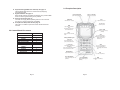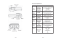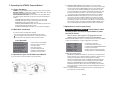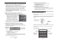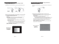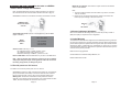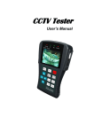
1
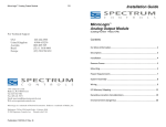
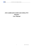
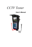
Camera ✭ Wizard
TM
COLOR & BW CCTV TESTER
WITH ON-SCREEN Vpp DISPLAY
ON-SCREEN Vpp DISPLAY
Camera: Color visual display and signal levels (Vpp)
Motion: Keypad control of Pan/Tilt/Zoom (PTZ)
Monitors: Drive with color bars and solid colors
Keyboards: RS485 serial data decoding
Cable testing: UTP (Cat 5/6)
Multimeter: AC/DC and resistance (probes included)
© 2009 Byte Brothers, Inc.
www.bytebrothers.com
Network Test and Repair Tools
7003 132nd Place SE, Newcastle, WA 98059 USA
+1.425.917.8380 ● FAX +1.425.917.8379 ● [email protected]
Model VTX454 User’s Manual
1. Safety Information
1.1 Precautions when using the Camera Wizard
Table of Contents
1. Safety Information……………………………...........…………........………
2
1.1 Precautions when using the Camera Wizard.…..............................
1.2 Precautions when charging and the battery…….....................……
2
2
2. Introduction………………………………………….…...................………..
2
2.1 Features and function…………………….……...................….………
2.2 Camera Wizard Kit contents.…………………..................…...………
2.3 Faceplate Description...………….…………..................……..……….
2.4 Technical Specifications………....…………..................……...………
2
3
4
6
3. Operating the VTX454 Camera Wizard………..................………….……
7
3.1 Power and battery……………….………………..................……..…...
3.2 Main Menu introduction…………………….……..................……...…
3.3 Quick test of your new VTX454 Camera Wizard................……....…
3.4 Main Menu...................................................................................……
Selection 1. System setup….………………………..........…..........…
Selection 2. Video, Signal strength; and PTZ Test…......................
Selection 3. UTP Cable Testing...................................………...........
Selection 4. Video Generator……………....…...............................…
Selection 5. RS485 Data Test………………...............................…….
Selection 6. Multimeter.....…………………….................…….....……
3.5 Provide power to a 12V camera……..………....…….....................…
3.6 Screen brightness adjustment..…………...…….…...................……
7
7
7
8
8
9
10
11
12
13
13
14
4. Warranty………………………………………………..…..................………
14
Page 1
A.
B.
C.
D.
E.
F.
G.
Please read this manual before using the product.
Always be cautious when working around voltage.
Do not use the tester in damp or explosive environments.
Areas of strong electromagnetism can cause incorrect measurements.
Do not expose the tester to dirt or liquid.
Do not disassemble the tester.
Operating environment:
Temperature: -30 C --- 70 C
Relative humidity: 30% ~ 90%
Recharging voltage:DC5V
1.2 Precautions when charging the battery
A. Use only the original, chargeable battery that came with the tester.
When charging, please use the original power adapter.
B. Make sure the batteries are installed correctly (polarity).
C. Do not short-circuit or disassemble batteries.
2. Introduction
2.1 Features and function
A. Camera video testing (Visual). See page 9.
Test a CCTV camera’s video output visually by displaying it on the
tester’s color LCD screen or loop the signal through to a video monitor.
B. Camera video testing (Signal strength). See page 9.
Perform a signal attenuation test with the touch of a button. The video
signal’s voltage (max and average Vpp) is displayed as is synch voltage.
Perfect for detecting weak signals. Also measures synch voltage.
C. Camera motion testing (PTZ). See page 9.
Test a PTZ camera’s pan, tilt, and zoom directly from the tester’s key
pad. Complete with preset settings and speed adjustment. Supports
RS-232, RS422 simplex and RS485 connections. Baud rates of 2400,
4800, 9600 and 19,200. RS485 protocol includes: Pelco D,P, Samsung,
Panasonic, Molynx and more.
D. Monitor testing (Video signal generator). See page 11.
Inspect monitors and DVRs by driving them with a known good video
signal from the tester. It can output color bars and separate colors.
The Camera Wizard only supports NTSC format.
Page 2
2.3 Faceplate Description
E. Keyboard testing (RS485 serial data test). See page 12.
Test the RS485 data sent from a control device by displaying
its hexadecimal data.
F. Digital multimeter. See page 13.
Detect AC/DC voltages and measure resistance using a built-in DMM.
Useful in measuring and isolating circuit problems.
G. Power to camera. See page 13.
The tester can supply DC12V (200ma) power to a CCTV camera.
Use when no camera power supply is available.
H. UTP (CAT 5 or CAT6) cable test. See page 10.
Test CAT 5 or 6 cables for opens and shorts. Remote terminator
included.
2.2 Camera Wizard Kit contents
Camera Wizard Kit
Contents
CCTV tester
Battery
Charger
UTP cable terminator
BNC connect cable
BNC/RCA adapter
PTZ screw/alligator
adapter
DMM test leads
Lanyard
DC12V power cable
User manual
1
1
1
1
1
1
1
1
1
1
1
Power
Lights when tester is ON
CHARGE LED
When ON tester is charging.
2.5” LCD Screen
960x240 resolution
OPEN
Open camera iris (PTZ Test)
SET
A multipurpose button used to
start or enable functions.
CLOSE - CLEAR
Close camera iris and clear setup
(PTZ Test)
Menu
Hold to return back to the Main
Menu
TELE
Zooms IN lens (PTZ Test)
Switches generated video to
VIDEO OUT jack (Video
Generator test)
MAX Vpp, AVERAGE Vpp and
Synch signal
Press during Video Test for
quick, accurate signal analysis
WIDE
Zooms OUT lens (PTZ Test)
Switches generated video to
tester display (Video Generator
Test)
0 - 9 number keys
Input numbers for PTZ function
Arrow keys
Move camera up,down,right,left (PTZ
Test). Also menu cursor control.
ADDR (ADDRESS)
Setup a PTZ ID (PTZ test)
S-PST (SETUP PRESET)
Setup a preset PTZ position
(PTZ Test)
Page 3
Data receive (PTZ data)
Lights when receiving data
Data transmit (PTZ data)
Lights when transmitting data
FAR
Focus lens to far (PTZ test)
C-PST (CALL PRESET)
Recall stored PTZ position
(PTZ Test)
Page 4
NEAR
Focus lens to near (PTZ test)
2.4 Technical Specifications
RS232 port.
Power ON/OFF
DC12V Power output jack
To power camera .
DC5V Power input jack
Connect charger here.
Feature
Video
Testing
Signal Mode
LCD Display
Signal strength
Video Input
Video Output
LCD Brightness
NTSC/PAL compatible
2.5 inch LCD screen, 960x240 resolution
Max Vpp, Ave Vpp and Synch V
1 channel BNC
1 channel BNC
Adjustable from keypad
PTZ Test
and
control
Communication
Protocol
Baud Rate
RS232, RS422 simplex and RS485
Includes 20 manufacturer’s protocols
2400, 4800, 9600, 19200
Built-in
Multimeter
DC Voltage Test
AC Voltage Test
Resistance Test
Max:1000V, Precision:0.1mV
Max:750V, Precision:0.1mV
Max:40Mohm , Precision: 0.1ohm
Power to
Camera
Voltage
Working Time
Max Current
DC12V
4-5 hours to normal camera
200mA
Other
Functions
UTP Cable Test
Signal Generator
RS485 Data Test
OSD Menu
Keypad
Test UTP (Cat 5,6) cables
Test security monitors
Display RS485 data from device
English OSD menu
Easy to operate. Number buttons.
Power and
Battery
Power Adapter
Battery
Rechargeable
Low Consumption
Operating Time
DC5V
3000mAh rechargeable battery inside
6 hours recharging time
Sleep mode. Power status display.
10 hours
Work Temperature
-22 F --- +158 F
-30 C --- +70 C
30%-90%
6.5”x3.6”x1.9”
16.6cmx9.1cmx4.8cm
.6#
280g
CAT5/6 UTP
Cable Test jack
Other
Video input
Connect camera here.
RS422/RS485 port
Connect PTZ to +T and -T
Connect keyboard to +R and -R
Page 5
Video output
Connect monitor here.
Camera Wizard CCTV Tester
Work Humidity
Dimension
Weight
Page 6
A. Viewing a camera image: Follow diagram A to connect a CCTV
camera (including PTZ control) to the tester. The camera’s video output
connects to the tester’s VIDEO IN BNC connector. The camera’s PTZ
control wires connect to tester’s RS484/422 control block (using the
screw terminal/alligator clip adapter provided with the tester). Turn ON
the tester and select menu item “2”. The camera’s video will display
on the tester screen. More detailed instructions follow in this manual.
B. Connect a monitor: Follow diagram B to connect a CCTV monitor
to the tester. The tester’s VIDEO OUT BNC connects to the monitor’s
video input connector. You can drive the monitor with the video signal
generated by the tester (menu item #4, then TELE) or in “looped mode”
with a camera’s video connected to the tester’s VIDEO IN BNC (menu
item #4, then WIDE). More detailed instructions follow in this manual.
3. Operating the VTX454 Camera Wizard
3.1 Power and battery
POWER: The power ON/OFF switch is located on the side of the tester.
BATTERY SAVER: The tester has a battery saving sleep mode. Turn the
slide switch ON again if the tester is asleep.
RECHARGEABLE BATTERY: The tester has a non-removable battery
for a larger capacity. Please do not open the rear panel and attempt to
repair it.
CHARGE TIME: The battery requires 5 hours for a full charge.
CHARGE LED: While charging, the “Charge” LED will be ON.
OPERATING TIME: Approximately 10 hours.
WHEN TO RECHARGE: Recharge when the battery indicator in the
System Setup menu shows 25% or less.
USE WHILE CHARGING: The tester can be used during charging.
3.2 Main Menu introduction
Turn on the device. The Main Menu appears:
#1 is the setup mode. #2 thru #6 selects five test modes.
Use the keypad’s numbered buttons to select the menu item.
The last item is the software version and serial number.
3.4 Main Menu (in order of appearance)
SELECTION 1. SYSTEM SETUP Display battery status;
set auto-off time; and setup PTZ parameters to match
your CCTV camera.
Note: If you are not using the PTZ (pan/tilt/zoom) test
feature, there is no need to set the PTZ parameters.
ENTERING AND EXITING: Press “1” to enter the setup screen. Press MENU
to return to the Main Menu. A typical configuration is as follows:
VTX454 MAIN MENU
1 SYSTEM SETUP
2 VIDEO AND PTZ TEST
3 UTP CABLE TEST
4 VIDEO GENERATOR
5 RS485 DATA TEST
6 MULTIMETER
VER:V1.11 S/N:08110910
.
> Setup PTZ and check battery
> Test video and control PTZ
> Test UTP cables
> Test video monitors
> Analyze RS485 protocol
> Measure voltage/resistance
> Software version and S/N
3.3 Quick test of your new VTX454 Camera Wizard
If you are anxious to use the VTX454, try these two tests.
A
B
Page 7
PROTOCOL Pelco P
COM
485
RATE
4800
SPEED
016
IDLE TIME 000
BATTERY 090
> PTZ protocol of camera
> PTZ communication port type
> PTZ baud rate: 2400/4800/9600/19200
> PTZ pan and tilt speed
> Battery saver turn off time (minutes)
> Battery status (%):100/90/75/50/25/5
MODIFYING THE SETTINGS:
ENTER SETUP MODE: Press SET. In this mode you 1) modify the PTZ
settings (Protocol, Com, Rate and Speed) to match the camera you are
testing 2) set the battery saver turn off time (when no activity).
SELECT THE ITEM: Press the UP and DOWN arrows to blink the line
you wish to modify. Battery status (% remaining) cannot be modified.
ADJUST THE PARAMETER: Press the UP/DOWN/RIGHT arrow.
SAVE/EXIT. Press the LEFT arrow to save the setting. Press the LEFT
arrow again to stop the blinking. Exit by holding the MENU key to return
to the Main Menu.
Notes: The Camera Wizard has 20 PTZ protocols and 17 speed settings (1 is
the slowest and 16 is the fastest).
Page 8
SELECTION 2. VIDEO; SIGNAL STRENGTH; AND PTZ TEST
A. Display a camera’s video signal on THE LCD and monitor:
Connection: Connect the camera to the tester as shown in figure A on
page 7. The camera connects to the tester’s VIDEO IN jack.
Display camera video: Press “2” on the keypad to turn ON the tester’s video
and PTZ feature. The camera’s video appears on the color LCD display. The
camera’s video will also appear on a monitor (if connected to the tester’s
VIDEO OUT jack). Study the image for proper focus and viewing angle.
Study the voltage readout (below) for proper amplitude. And use the tester’s
PTZ feature (below) to control pan, tilt and zoom.
Adjust LCD brightness: Use keys number 7 (BR+) and 9 (BR-) to adjust the
LCD screen’s brightness.
Controlling the camera’s PTZ. (pan/tilt/zoom)
Press UP/DOWN/LEFT/RIGHT to control the movement.
Press OPEN/CLOSE to control the iris.
Pres FAR/NEAR to adjust focus.
Press WIDE/TELE to zoom the camera lens in and out.
Saving and Calling Preset positions:
The Video Wizard can Save and Call preset positions.
To Save: Press S-PST and input a position number. Press SET to save.
To Call: Press C-PST and input the position number. Press SET to call.
Multiple preset positions can be saved.
SELECTION 3. UTP CABLE TESTING Testing a UTP cable
(CAT5/6) for proper connection.
B. Measure signal strength (Vpp) and attenuation:
Video signal strength (attenuation): With the tester displaying the video
signal (see above), press the “1” (IRE) key. The following is displayed:
MAX Vpp: The peak-to-peak amplitude of the
video signal. The larger the video signal, the
brighter the picture. 1 Vpp is minimum.
AVERAGE Vpp: The average peak-to-peak
amplitude of the video signal amplitude.
SYNC SIGNAL: A camera’s synch pulses
synchronize the camera with the monitor’.
No video: No signal, “No Video” will be displayed.
Example of attenuation: If the Vpp at the camera is 1.25Vpp and the Vpp at
the end of the cable is 1.15V, the attenuation is 8%.
Note: “UTP” means unshielded twisted pair. UTP is the most common type of
CAT5 and 6 cable.
Connection: Connect the Cat 5/6 UTP cable to the UTP TEST socket on the
right side of the tester. Connect the Remote Terminator to the far end of
the cable.
TESTING A CAT 5
AND 6 CABLE (UTP)
REMOTE
TERMINATOR
C. Testing and controlling the camera motion (PTZ).
Connection. Connect the camera to the tester as shown in figure A on
page 7. The camera’s PTZ wires plug into the T+ and T- ports on the tester’s
RS422/485 jack (use adapter).
Enter the PTZ
camera’s ID
(001 -255)
ADDRESS:001
VIDEO:NULL
Video format
PAL/NTSC/NULL
Select UTP Cable Test mode: Press the “3” key to enter the UTP test mode.
Start test: Press SET. The Cat 5/6 UTP cable wiremap will be displayed
on the LCD screen.
Return to Main Menu: Hold the MENU key to return to the Main Menu.
UTP CABLE TEST
Enter the camera’s ID.
Press ADDR and input the PTZ camera’s ID.
Press SET to save the address.
Press MENU to hide the menu display.
Hold MENU to exit the video/PTZ function and return to the Main Menu.
Note: See System Setup (page 8) to match the tester’s PTZ protocol, com
type and baud rate to that of the camera.
Continued on following page
Page 9
TESTER SIDE
PIN NUMBERS
TYPICAL CAT 5/6
CABLE (UTP)
WIREMAP
1
2
3
4
5
6
7
8
---------------------------------
--------------------------------Page 10
1
2
3
0
0
6
7
8
REMOTE SIDE
PIN NUMBERS
“0” means open circuit
Two “0” is a short circuit
PIN NUMBERS
SELECTION 4. VIDEO GENERATOR Testing a monitor
using the VIDEO OUT port
Connection. Connect the monitor to the tester using the VIDEO OUT jack:
WITHOUT
CAMERA
SELECTION 5. RS485 DATA TEST Analyze data from a
RS485 device (keyboard)
Connection. Connect the device to the tester using the +R -R sockets (use
adapter).
WITH
CAMERA
Drive the monitor with the tester’s video generator. Or drive the monitor
with a camera “looped” through the tester.
Select Video Generator mode: Press the “4” key to turn ON the video
generator.
Select options: Use the following keys to control the options:
SET Selects the tester’s video signal: Color bar, Blue, Red, Pink,
Green, Cyan, Yellow and White.
TELE Switches the tester’s video signal to the monitor (connected
to the VIDEO OUT jack).
WIDE Switches the video signal so it loops from the VIDEO IN jack to
the VIDEO OUT jack. In this mode, a picture will only appear on
the monitor if a camera is connected to the VIDEO IN jack.
Return to Main Menu: Hold the Main Menu key to turn OFF the video
generator and return to the Main Menu.
Display the device’s hexadecimal output on the tester’s LCD.
Select the Data Test mode: Press the “5” key to turn ON the RS485
protocol analyzer.
Select options: Use the following keys to control the options:
SET Enables the changing of the Baud rate.
UP/DOWN ARROW KEYS Changes the tester’s Baud rate. Select the
Baud rate that matches the device that is being analyzed.
Data transfer will start automatically through the RS485 port. The hexadecimal data is displayed on the tester’s screen as shown below.
Analysis of the data will indicate its protocol.
Return to Main Menu: Hold the Main Menu key to turn OFF the data
flow and return to the Main Menu.
A0 00 01 00 00 00 AF 0F
Typical hexadecimal
data from a
RS485 device
Video Generator
(Press SET to
select and TELE
to output)
A0 00 01 00 00 00 AF 0E
A0 00 01 00 00 00 AF 0F
A0 00 01 00 00 00 AF 4F
A0 00 01 00 00 00 AF EF
A0 00 01 00 00 00 AF 2F
Page 11
Page 12
SELECTION 6. MULTIMETER Use the tester as a DMM to
measure AC/DC voltage and resistance
Maximum current/power: The maximum output current from the tester is
200ma / 2400 milliwatts.
Note: The tester displays the Vpp of the video signal and synch signal on
the LCD without the use of the test leads. See Menu Item #4 on page 11.
Note:
1. The output voltage of tester is DC12V. Please only use the connection
with 12V cameras.
2. Please do not connect the tester’s DC12V output to the testers own
DC5V input jack. Damage to the tester will occur.
Connection: Connect the 2 test leads to the bottom of the tester as shown:
DMM test leads
attached to bottom
of tester
Powering
a
12V camera
3.6 Screen brightness adjustment
Select Multimeter mode: Press “6” on the keypad to turn ON the DMM
(digital multimeter).
DC:-121.3mV
Digital
Multimeter
Menu
1 DC VOLTAGE
2 AC VOLTAGE
3 RESISTANCE
Select function: Press key 1, 2 or 3.
DC voltage test range: 0-1000V, precision: 0.1mV
AC voltage test range: 750V, precision: 0.1mV
Resistance test range: 0-40Mohm , precision: 0.1ohm
Return to Main Menu: Hold the Main Menu key to return to the Main Menu.
Note: Exercise caution when voltage is present. If you are not familiar
with proper safety techniques, ask for guidance. Please do not exceed
the testing range (above) or damage may occur
When in the Video and PTZ testing mode (menu item #2) use keys number 7
(BR+) and 9 (BR-) to adjust the screen’s brightness.
4. Limited Warranty
The manufacturer warrants to the original consumer that this product is in good working order for a period of one year from the date of purchase. During this period the
product will be repaired or replaced without charge for either parts or labor. Testers
damaged by abuse, unreasonable use, mistreatment or neglect are not covered
under this warranty. Repair or replacement as provided under this warranty is the
exclusive remedy of the purchaser.
Made in China. Copyright 2009.
Camera Wizard is a trademark of Byte Brothers, Inc.
Model VTX454 User's Guide
3.5 Provide power to a 12V camera
The tester can be used to provide power to a 12V camera.
Connection: Connect the cable (included) to the tester’s “DC 12V OUTPUT”
jack (on the left side of the tester). Connect the other end to the camera’s
DC12V power input jack. Use only with 12V DC cameras (200ma max).
Working time: The amount of time that the tester powers the camera
depends on the camera’s power consumption. If the camera draws less than
100ma, the tester will power the camera for about 4 hours.
Page 13
Page 14