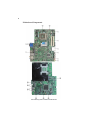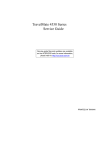
1
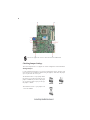
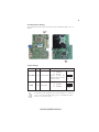
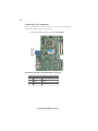
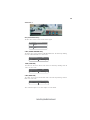
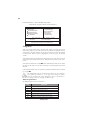
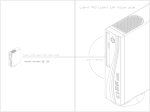
Preface
Copyright
This publication, including all photographs, illustrations and software, is protected
under international copyright laws, with all rights reserved. Neither this manual, nor
any of the material contained herein, may be reproduced without written consent of
the author.
Version 1.0
Disclaimer
The information in this document is subject to change without notice. The manufacturer makes no representations or warranties with respect to the contents hereof and
specifically disclaims any implied warranties of merchantability or fitness for any
particular purpose. The manufacturer reserves the right to revise this publication and
to make changes from time to time in the content hereof without obligation of the
manufacturer to notify any person of such revision or changes.
Trademark Recognition
Microsoft, MS-DOS and Windows are registered trademarks of Microsoft Corp.
MMX, Pentium, Pentium-II, Pentium-III, Celeron are registered trademarks of Intel
Corporation.
Other product names used in this manual are the properties of their respective
owners and are acknowledged.
Federal Communications Commission (FCC)
This equipment has been tested and found to comply with the limits for a Class B
digital device, pursuant to Part 15 of the FCC Rules. These limits are designed to
provide reasonable protection against harmful interference in a residential installation. This equipment generates, uses, and can radiate radio frequency energy and, if
not installed and used in accordance with the instructions, may cause harmful interference to radio communications. However, there is no guarantee that interference
will not occur in a particular installation. If this equipment does cause harmful
interference to radio or television reception, which can be determined by turning the
equipment off and on, the user is encouraged to try to correct the interference by one
or more of the following measures:
•
•
•
•
Reorient or relocate the receiving antenna
Increase the separation between the equipment and the receiver
Connect the equipment onto an outlet on a circuit different from that to
which the receiver is connected
Consult the dealer or an experienced radio/TV technician for help
Shielded interconnect cables and a shielded AC power cable must be employed with
this equipment to ensure compliance with the pertinent RF emission limits governing
this device. Changes or modifications not expressly approved by the system’s manufacturer could void the user’s authority to operate the equipment.
Preface
ii
Declaration of Conformity
This device complies with part 15 of the FCC rules. Operation is subject to the
following conditions:
•
•
This device may not cause harmful interference, and
This device must accept any interference received, including interference that may cause undesired operation
Canadian Department of Communications
This class B digital apparatus meets all requirements of the Canadian Interferencecausing Equipment Regulations.
Cet appareil numérique de la classe B respecte toutes les exigences du Réglement sur
le matériel brouilieur du Canada.
About the Manual
The manual consists of the following:
Chapter 1
Introducing the 3L Small Form
Factor
Chapter 2
Describes features of the 3L
Small Form Factor.
Go to
H
page 1
Describes installation of
motherboard components.
Installing the Motherboard
Go to
Chapter 3
H
page 7
Provides information on using the BIOS Setup Utility.
Using BIOS
Go to
Chapter 4
Using the Motherboard Software
Intel® Remote Wake Technology
H
page 43
Describes the Intel® Remote
Wake Technology.
Go to
Preface
page 25
Describes the motherboard
software.
Go to
Chapter 5
H
H
page 53
iii
TABLE OF CONTENTS
Preface
i
Chapter 1
1
Introducing the 3L Small Form Factor
1
Introducing the 3L Small Form Factor...........................................1
Feature of the motherboard.............................................................2
Motherboard Components.............................................................4
Chapter 2
7
Installing the Motherboard
7
Safety Precautions............................................................................7
Choosing a Computer Case.............................................................7
Installing the Motherboard in a Case............................................7
Checking Jumper Settings...............................................................8
Setting Jumpers...................................................................8
Checking Jumper Settings...................................................9
Jumper Settings...................................................................9
Installing Hardware.........................................................................10
Installing the Processor.....................................................10
Installing Memory Modules...............................................12
Expansion Slots.................................................................16
Connecting Optional Devices............................................17
Installing SATA_HDD/SATA_ODD...................................20
Connecting I/O Devices................................................................21
Connecting Case Components.....................................................22
IR1/LED1~3......................................................................23
Chapter 3
25
Using BIOS
25
About the Setup Utility..................................................................25
The Standard Configuration..............................................25
Entering the Setup Utility...................................................25
Using BIOS......................................................................................26
Standard CMOS Setup......................................................27
Advanced Setup.................................................................29
Advanced Chipset Setup....................................................32
iv
Integrated Peripherals.......................................................34
Power Management Setup.................................................35
PC Health Status...............................................................36
Frequency/Voltage Control................................................38
Load Default Settings........................................................39
Supervisor Password........................................................39
User Password..................................................................40
Save & Exit Setup..............................................................40
Exit Without Saving............................................................40
Updating the BIOS.............................................................41
Chapter 4
43
Using the Motherboard Software
43
About the Software CD-ROM......................................................43
Auto-installing under Windows Vista.........................................43
Running Setup....................................................................44
Manual Installation........................................................................48
Utility Software Reference............................................................48
HDMI Audio setting SOP............................................................49
Chapter 5
53
®
Intel Remote Wake Technology
53
®
About the Intel Remote Wake Technology..............................53
IRWT Installation and Setup........................................................54
Driver and Software Installation......................................54
Getting Ready for Remote Wake.......................................55
Put Your Computer to Sleep Mode....................................57
1
Chapter 1
Introducing the 3L Small Form Factor
Introducing the 3L Small Form Factor
Thank you for choosing 3L Small Form Factor of great performance and with stylish
and flexible design.
With Intel® CoreTM 2 Duo/Celeron® processors inside and a dimension of 270mm
(H)* 200mm (D)* 60mm (W) (3 Liter), 3L Small Form Factor provides the features
of low power consumption (working with a 65Watt power adaptor), low noise (<28dB)
and space saving. It incorporates the G43 Northbridge (NB) and ICH10 Southbridge
(SB) chipsets, supporting up to 4 GB of system memory with DDR2 memory SODIMM
frequencies of 800/667 MHz, 3.5” SATA II HDD, Slim DVD Supermulti Slot-in type
ODD, and Built in Intel® GMA X4500 Graphics.
3L Small Form Factor is equipped with four USB 2.0 ports, two audio ports, one
1394a port (optional) in the front panel and advanced full set of I/O ports in the rear
panel, including J4, one VGA port, one HDMI port, four USB ports, one ESATA port,
one LAN port, one optical SPDIFO port, and audio jacks for microphone, line-in and
8-ch line-out.
Introducing the 3L Small Form Factor
2
Feature of the motherboard
Processor
The motherboard uses an LGA775 type of Intel® CoreTM 2 Duo/Celeron® processors that carries the following features:
•
•
•
Accommodates Intel® CoreTM 2 Duo/Celeron® processors
Supports a system bus (FSB) of 1333/1066/800 MHz
Supports “Hyper-Threading” technology CPU
“Hyper-Threading” technology enables the operating system into thinking it’s
hooked up to two processors, allowing two threads to be run in parallel, both on
separate “logical” processors within the same physical processor.
Chipset
The Intel® G43 Northbridge (NB) and Intel® ICH10 Southbridge (SB) chipsets
are based on an innovative and scalable architecture with proven reliability and
performance.
G43
(NB)
•
•
•
•
•
•
ICH10
(SB)
•
•
•
•
Supports 36-bit host bus addressing, allowing the CPU to
access the entire 64 GB of the memory address space
Chip-to-chip connection interface to Intel ICH10
2 GB/s point-to-point Direct Media Interface (DMI) to ICH10
(1 GB/s each direction)
Supports 2-Gb,1-Gb and 512-Mb DDR2 DRAM technologies for x8 and x16 devices
An integrated graphics device (IGD) delivering cost competitive 3D, 2D and video capabilities
Two MINI PCI Express ports intended for external devices
attach
Enhanced DMA Controller, Timer/Counter functions, and
Interrupt Controller
Integrated SATA 3.0 Gb/s Host Controller
Integrated USB 2.0 Host Controller supporting up to eight
USB 2.0 ports
Integrated Gigabit LAN Controller
Memory
•
•
•
Supports DDR2 800/667 DDR2 SDRAM with Dual-channel architecture
Accommodates two unbuffered SO-DIMMs
Up to 2 GB per DIMM with maximum memory size up to 4 GB
Audio
•
•
•
•
•
All DACs support 192K/96K/48K/44.1KHz DAC sample rate
High-quality analog differential CD input
Software selectable 2.5V/3.75V VREFOUT
Meets Microsoft WLP 3.08 audio requirements
Direct Sound 3DTM compatible
Introducing the 3L Small Form Factor
3
Onboard LAN
•
•
•
Integrated Intel Gigabit Ethernet Controller for PCI ExpressTM Applications
Integrated 10/100/1000 transceiver
Wake-on-LAN and remote wake-up support
1394a FireWire (optional)
•
•
•
Compliant with single chip host controller for IEEE Std 1394-1995 and
IEEE 1394a-2000
Integrated 400 Mb/s 2-Port PHY for the PCI BUS
3.3V Power supply with 5V Tolerant Inputs
Expansion Options
The motherboard comes with the following expansion options:
•
•
•
•
Two SCN slots (MINI PCI Express slots)
One SATA_HDD1 connector
One SATA_ODD1 connector
One TV1 header
Integrated I/O
The motherboard has a full set of I/O ports and connectors:
•
One J4 port (DC Jack)
•
One VGA port
•
One HDMI port
•
Four USB ports
•
One ESATA port
•
One LAN port
•
One optical SPDIFO port
•
Audio jacks for microphone, line-in and 8-ch High Definition Audio
output
BIOS Firmware
This motherboard uses AMI BIOS that enables users to configure many system
features including the following:
•
Power management
•
Wake-up alarms
•
CPU parameters
•
CPU and memory timing
The firmware can also be used to set parameters for different processor clock
speeds.
1. Some hardware specifications and software items are subject to change
without prior notice.
2. Due to chipset limitation, we recommend that motherboard be operated in the ambiance between 0 and 50 ° C.
Introducing the 3L Small Form Factor
4
Motherboard Components
Introducing the 3L Small Form Factor
5
Table of Motherboard Components
LABEL
1. CPU Socket
2. CLR_CMOS1
3. J3
4. CN1~2
5. CN7*
6.1394A1*
7. JMIC1
8. JPHOME1
9. SATA_HDD1
10. SYS_FAN1~2
11. SATA_ODD1
12. MED1
13. SPI_ROM1
14. COM1
15. F_USB1~4
16. SCN1~2
17. TV1*
*
COMPONENTS
Intel® CoreTM 2 Duo/Celeron TM processors
Clear CMOS jumper
SATA HDD power connector
Two 200-pin DDR2 SDRAM SO-DIMMs
Reader Card
Onboard 1394a connector
Front MIC
Front LINE IN
SATA HDD connector
System cooling fan connectors
SATA ODD connector
ME Disable jumper
SPI ROM header
Onboard serial port header
Front panel USB ports
MINI PCI Express slots
External S-VIDEO header
Stands for optional components
This concludes Chapter 1. The next chapter explains how to install the motherboard.
Introducing the 3L Small Form Factor
6
Memo
Introducing the 3L Small Form Factor
7
Chapter 2
Installing the Motherboard
Safety Precautions
•
•
•
•
•
Follow these safety precautions when installing the motherboard
Wear a grounding strap attached to a grounded device to avoid damage from static electricity
Discharge static electricity by touching the metal case of a safely
grounded object before working on the motherboard
Leave components in the static-proof bags they came in
Hold all circuit boards by the edges. Do not bend circuit boards
Choosing a Computer Case
There are many types of computer cases on the market. The motherboard complies
with the specifications for the small system case. Some features on the motherboard
are implemented by cabling connectors on the motherboard to indicators and switches
on the system case. Make sure that your case supports all the features required.
Most cases have a choice of I/O templates in the rear panel. Make sure that the I/O
template in the case matches the I/O ports installed on the rear edge of the
motherboard.
This motherboard carries a small form factor of 236 x 195 mm. Choose a case that
accommodates this form factor.
Installing the Motherboard in a Case
Refer to the following illustration and instructions for installing the motherboard in
a case.
Most system cases have mounting brackets installed in the case, which correspond
the holes in the motherboard. Place the motherboard over the mounting brackets
and secure the motherboard onto the mounting brackets with screws.
Ensure that your case has an I/O template that supports the I/O ports and expansion
slots on your motherboard.
Installing the Motherboard
8
Do not over-tighten the screws as this can stress the motherboard.
Checking Jumper Settings
This section explains how to set jumpers for correct configuration of the motherboard.
Setting Jumpers
Use the motherboard jumpers to set system configuration options. Jumpers with
more than one pin are numbered. When setting the jumpers, ensure that the jumper
caps are placed on the correct pins.
The illustrations show a 2-pin jumper. When
the jumper cap is placed on both pins, the
jumper is SHORT. If you remove the jumper
cap, or place the jumper cap on just one pin,
the jumper is OPEN.
SHORT
This illustration shows a 3-pin jumper. Pins
1 and 2 are SHORT.
Installing the Motherboard
OPEN
9
Checking Jumper Settings
The following illustration shows the location of the motherboard jumpers. Pin 1 is
labeled.
Jumper Settings
Jumper
Type
Description
Setting (default)
1-2: NORMAL
CLR_CMOS1 3-pin
MED1
3-pin
CLEAR CMOS
ME Disable
2-3: CLEAR
Before clearing the
CMOS, make sure to turn
off the system.
1
CLR_CMOS1
1-2: ENABLE
2-3: DISABLE
1
MED1
To avoid the system instability after clearing CMOS1, we recommend
users to enter the main BIOS setting page to “Load Default Settings”
and then “Save & Exit Setup”.
Installing the Motherboard
10
Installing Hardware
Installing the Processor
Caution: When installing a CPU heatsink and cooling fan make sure
that you DO NOT scratch the motherboard or any of the surfacemount resistors with the clip of the cooling fan. If the clip of the
cooling fan scrapes across the motherboard, you may cause serious
damage to the motherboard or its components.
On most motherboards, there are small surface-mount resistors near
the processor socket, which may be damaged if the cooling fan is
carelessly installed.
Avoid using cooling fans with sharp edges on the fan casing and the
clips. Also, install the cooling fan in a well-lit work area so that you
can clearly see the motherboard and processor socket.
Before installing the Processor
This motherboard automatically determines the CPU clock frequency and system
bus frequency for the processor. You may be able to change the settings in the system
Setup Utility. We strongly recommend that you do not over-clock processors or
other components to run faster than their rated speed.
Warning:
1. Over-clocking components can adversely affect the reliability of
the system and introduce errors into your system. Over-clocking can
permanently damage the motherboard by generating excess heat in
components that are run beyond the rated limits.
2. Always remove the AC power by unplugging the power cord from
the power outlet before installing or removing the motherboard or
other hardware components.
This motherboard has an LGA775 socket. When choosing a processor, consider the
performance requirements of the system. Performance is based on the processor
design, the clock speed and system bus frequency of the processor, and the quantity
of internal cache memory and external cache memory.
Installing the Motherboard
11
CPU Installation Procedure
The following illustration shows CPU installation components.
A. Read and follow the instructions shown on the
sticker on the CPU cap.
B. Unload the cap
· Use thumb & forefinger to hold the
lifting tab of the cap.
· Lift the cap up and remove the cap
completely from the socket.
C. Open the load plate
· Use thumb & forefinger to hold the
hook of the lever, pushing down and pulling
aside unlock it.
· Lift up the lever.
· Use thumb to open the load plate. Be
careful not to touch the contacts.
D. Install the CPU on the socket
· Orientate CPU package to the socket.
Make sure you match triangle marker
to pin 1 location.
E. Close the load plate
· Slightly push down the load plate onto the
tongue side, and hook the lever.
· CPU is locked completely.
F.
Apply thermal grease on top of the CPU.
G. Fasten the cooling fan supporting base onto
the CPU socket on the motherboard.
H. Make sure the CPU fan is plugged to the
CPU fan connector. Please refer to the CPU
cooling fan user’s manual for more detail
installation procedure.
1. To achieve better airflow rates and heat dissipation, we suggest that you
use a high quality fan with 3800 rpm at least. CPU fan and heatsink
installation procedures may vary with the type of CPU fan/heatsink
supplied. The form and size of fan/heatsink may also vary.
2. DO NOT remove the CPU cap from the socket before installing a CPU.
3. Return Material Authorization (RMA) requests will be accepted only if
the motherboard comes with the cap on the LGA775 socket.
Installing the Motherboard
12
Installing Memory Modules
This motherboard accommodates two memory modules. It can support two 200-pin
DDR2 800/667. The total memory capacity is 4 GB.
DDR2 SDRAM memory module table
Memory module
Memory Bus
DDR2 667
DDR2 800
333 MHz
400 MHz
You must install at least one module in any of the two slots. Each module can be
installed with 2 GB of memory; total memory capacity is 4 GB.
Do not remove any memory module from its antistatic packaging
until you are ready to install it on the motherboard. Handle the
modules only by their edges. Do not touch the components or metal
parts. Always wear a grounding strap when you handle the modules.
Installing the Motherboard
13
Memory Module Installation Procedure
These modules can be installed with up to 4
GB system memory. Refer to the following
to install the memory module.
1. Align the memory module with the
DIMM slot. There is a notch on
the DIMM slot that you can install the DIMM module in the correct direction. Match the cutout on
the DIMM module with the notch
on the DIMM socket.
2. Insert the memory module to the
slot and press it down until it seats
correctly.
3. Make sure the slot latches cling to
the edge of the DIMM module.
Installing the Motherboard
14
Table A: DDR2 (memory module) QVL (Qualified Vendor List)
The following DDR2 800/667 memory modules and combination have been tested
and qualified for use with this motherboard.
Type
Size
Vendor
Module Nam e
256 MB
Samsung
M470T3354CZ3
Micron
MT4HTF6464HY-667E1
Ramaxel
RMN1150MD38D6F-667
RMN1150MD38D6F
512 MB
RMN1150HC38D6F-667
DDR2 667
1 GB
Sharetronic
SM221N516EAF
A-data
M2OAD5G3144B0I1C53
Apacer
78.02G72.9K2
Elixir
M2N1G64TUH8D4F-3C 0809.TW
Infinity
14701G16CX5D2A
Kingston
Nanya KVR667D2S5
Micron
MT8HTF12864HDY-667E1
NCP
ELPT7ASDR-30M48 NC 03389
Qimonda
HYS64T128021EDL-3S Y3E81226
Ramaxel
RMN1150HC48D7F-667
RMN1270ME56D7F
RMN1150HC48D7F
2 GB
Winchip
NEJA2450.A8ECW
Apacer
78.A2G72.9K5
Kingston
KVR667D2S5
HYS64T256020EDL-3S-C2
Z2S81023004
Qimonda
Winchip
NEJB4850.B8PDW
Installing the Motherboard
15
Type
Size
512 MB
Vendor
Module Nam e
Kingston
Apacer
KVR800D2S5
MT4HTF6464HY-800E1 200737
BZADXDB001
78.02G75.9K2
G.SKILL
F2-6400CL5D-2GBSA
Micron
Infinity
14701G16CZ5D2A
Nanya KVR800D2S6
Kingston
Hynix KVR800D2S6
KVR800D2S5
KVR800D2S6
1 GB
NCP
ELPT7ASDR-25M48NC 03388
PNY
NEKA450.A8ECP
PSC
AS7E8F63J-8E
Qimonda
HYS64T128021EDL-2.5B2 Y3E81027
Samsung
M470T2864QZ3-CF7
Transcend
DYnamic M0-U0 E150630 94V-0
Unifosa
GU331G0ALEPR612C6CE
Winchip
NEKA2450.A8ECW
Apacer
Elixir
M2N2G64TU8HD4B-AC 0805.TW
DDR2 800
216401-CL5
202410-0001[96]
2 GB
78.A2G75.9K5
Kingston
KVR800D2S6
Micron
MT16HTF25664HY-800E1
PNY
NEKB4850.B8PFP
PSC
AS8E8F73C-8E1
HYS64T256020EDL-2.5C2
Z2S81225022
Qimonda
Samsung
GOLD BAR M470T5663RZ3-CF7 0819
Unifosa
GU332G0ALEPR8H2C6CE
Winchip
NEKB4850.B8PDW
Installing the Motherboard
16
Expansion Slots
Installing Add-on Cards
The slots on this motherboard are designed to hold expansion cards and connect
them to the system bus. Expansion slots are a means of adding or enhancing the
motherboard’s features and capabilities. With these efficient facilities, you can
increase the motherboard’s capabilities by adding hardware that performs tasks that
are not part of the basic system.
SCN1~2 Slots
The SCN1~2 slots are used to install external PCI Express graphics cards.
Before installing an add-on card, check the documentation for
the card carefully. If the card is not Plug and Play, you may have
to manually configure the card before installation.
Table B: Supported Wireless LAN Card List for SCN1~2 Slots
Vendor
Module Name
Gemtek
WPEB-109N
LITEON
WN6500M
Installing the Motherboard
17
Connecting Optional Devices
Refer to the following for information on connecting the motherboard’s optional
devices:
Installing the Motherboard
18
J3: SATA HDD power connector
Pin
1
2
3
4
Signal Name
12V
GND
VCC3
5V
Function
12V power
Ground
J3 power
5V power
1394A1: IEEE 1394a connector (optional)
It can be used to connect any device with IEEE 1394a interface.
Pin
Pin
1
2
3
4
Signal
Signal Name
TPB-
Function
TPB+
TPATPA+
JMIC1: Front Audio Microphone Jack
Pin
1
3
5
Signal Name
GND
Pin
Signal Name
MIC2_L
2
4
6
MIC2_R
GND
MIC2_JD
N/C
JPHOME1: Front Audio Line-out Jack
Pin
1
3
5
Signal Name
Pin
Signal Name
2
4
6
GND
LINE2_R
GND
LINE2_L
LINE2_JD
N/C
SPI_ROM1: SPI ROM header
This 8 Mb ROM contains the programmable BIOS program.
Pin
Signal Name
Function
1
2
3
CHIP SELECT
4
5
6
7
HOLD
hold
WRITE PROTECT
BIOS write protect
8
Select chip
VCC
VCC
DATA OUTPUT
data output
CLOCK
clock
CND
CND
DATA INPUT
data input
Installing the Motherboard
19
COM1: Onboard serial port header
Connect a serial port extension bracket to this header to add a second serial port to
your system.
Pin
1
2
3
4
5
6
7
8
9
10
Signal Name
DCDB
DSRB
SINB
Function
Data Carrier Detect
Data Set Ready
Serial Input
RTSB
RART B Request to Send
SOUTB
UART B Serial Output
CTSB
Clear to Send
DTRB
RI
Ring Indicator
Key
GND
No pin
Ground
UART B Data Terminal Ready
TV1: External S-VIDEO Header (optional)
Pin
1
2
3
4
5
6
7
8
9
10
Signal Name
S_VIDEO_Y
S_VIDEO_C
AUDIO_R_IN
GND
AUDIO_L_IN
AV_IN
GND
GND
Key
GND
FUSB1~4: Front Panel USB Ports
The motherboard has four USB ports installed on the rear edge I/O port array.
Additionally, some computer cases have USB ports at the front of the case. If you
have this kind of case, use auxiliary USB connector to connect the front-mounted
ports to the motherboard.
Pin
1
3
5
7
Signal Name
VCC
data+
vcc
data+
Pin
2
4
6
8
Signal Name
datagnd
datagnd
Please make sure that the USB cable has the same pin assignment as
indicated above. A different pin assignment may cause damage or
system hang-up.
Installing the Motherboard
20
Installing SATA_HDD/SATA_ODD
About SATA_HDD1 Connector
This motherboard features one SATA HDD1 connector supporting one drive, and
you can connect a hard disk drive to the SATA_HDD1 port.
About SATA_ODD1 Connector
This motherboard features one SATA ODD1 connector supporting one drive, and
you can connect a hard disk drive to the SATA_ODD1 port.
Installing the Motherboard
21
Connecting I/O Devices
The backplane of the motherboard has the following I/O ports:
VGA1 Port
Connect your monitor to the VGA port.
HDMI Port
Connect the HDMI port to the HDMI devices.
USB Ports
Use the USB ports to connect USB devices.
ESATA1 Port
Use this port to connect to an external SATA box or a
Serial ATA port multiplier.
It is suggested that users use the eSATA hard disk with
external power.
LAN1 Port
Connect an RJ-45 jack to the LAN port to connect your
computer to the network.
J4
Connect a DC-in jack to J4.
Optical SPDIF
Output
This jack connects to external optical digital audio output
devices.
Audio Ports
Use the audio jacks to connect audio devices. The C port is
for stereo line-in signal, while the E port is for microphone
in signal. This motherboard supports audio devices that correspond to the A, B and D port respectively. In addition, all
of the 3 ports, B, and D provide users with both right & left
channels individually. Users please refer to the following
note for specific port function definition.
A : Center & Woofer
D : Front Out
B : Back Surround
E : Mic_in Rear
-
C : Line-in
The above port definition can be changed to audio input or
audio output by changing the driver utility setting.
Installing the Motherboard
22
Connecting Case Components
After you have installed the motherboard into a case, you can begin connecting the
motherboard components. Refer to the following:
1
Connect the system cooling fan connector to SYS_FAN1/2.
SYS_FAN1~2: System Cooling FAN Power Connectors
Pin
Signal Name
Function
1
2
3
GND
+12V
Sense
System Ground
Power +12V
Sensor
4
PWM
CPU FAN control
Installing the Motherboard
23
IR1/LED1~3
IR1 (Infrared Receiver)
The IR1 can be used to receive remote control signal.
Pin
1
2
3
Signal Name
IR_RX
GND
VCC
LED1 (CARD READER LED)
The LED1 can be used to indicate CARD READER status. The LED keeps blinking
when the CARD READER is in Active state.
System Status
Active
LED
Blinking
LED2 (LAN LED)
The LED2 can be used to indicate LAN status. The LED keeps blinking when the
LAN is in Active state.
System Status
Active
LED
Blinking
LED3 (HDD LED)
The LED3 can be used to indicate HDD status. The LED keeps blinking when the
HDD is in Active state.
System Status
Active
LED
Blinking
This concludes Chapter 2. The next chapter covers the BIOS.
Installing the Motherboard
24
Memo
Installing the Motherboard
25
Chapter 3
Using BIOS
About the Setup Utility
The computer uses the latest “American Megatrends Inc.” BIOS with support for
Windows Plug and Play. The CMOS chip on the motherboard contains the ROM
setup instructions for configuring the motherboard BIOS.
The BIOS (Basic Input and Output System) Setup Utility displays the system’s
configuration status and provides you with options to set system parameters. The
parameters are stored in battery-backed-up CMOS RAM that saves this information
when the power is turned off. When the system is turned back on, the system is
configured with the values you stored in CMOS.
The BIOS Setup Utility enables you to configure:
•
•
•
•
Hard drives, diskette drives and peripherals
Video display type and display options
Password protection from unauthorized use
Power Management features
The settings made in the Setup Utility affect how the computer performs. Before
using the Setup Utility, ensure that you understand the Setup Utility options.
This chapter provides explanations for Setup Utility options.
The Standard Configuration
A standard configuration has already been set in the Setup Utility. However, we
recommend that you read this chapter in case you need to make any changes in the
future.
This Setup Utility should be used:
•
•
•
•
•
when changing the system configuration
when a configuration error is detected and you are prompted to make
changes to the Setup Utility
when trying to resolve IRQ conflicts
when making changes to the Power Management configuration
when changing the password or making other changes to the Security
Setup
Entering the Setup Utility
When you power on the system, BIOS enters the Power-On Self Test (POST)
routines. POST is a series of built-in diagnostics performed by the BIOS. After the
POST routines are completed, the following message appears:
Press DEL to enter SETUP
Using BIOS
26
Press the delete key to access the BIOS Setup Utility.
CMOS Setup Utility - Copyright (C) 1985-2005, American Megatrends, Inc.
fStandard CMOS Setup
fAdvanced Setup
fAdvanced Chipset Setup
fIntegrated Peripherals
fPower Management Setup
fPC Health Status
fFrequency/Voltage Control
Load Default Settings
fSupervisor Password
fUser Password
Save & Exit Setup
Exit Without Saving
mnlk : Move Enter : Select
F1:General Help
+/-/: Value F10: Save ESC: Exit
F9: Load default settings
v02.63 (C)Copyright 1985-2008, American Megatrends, Inc.
Using BIOS
When you start the Setup Utility, the main menu appears. The main menu of the
Setup Utility displays a list of the options that are available. A highlight indicates
which option is currently selected. Use the cursor arrow keys to move the highlight
to other options. When an option is highlighted, execute the option by pressing
<Enter>.
Some options lead to pop-up dialog boxes that prompt you to verify that you wish to
execute that option. Other options lead to dialog boxes that prompt you for information.
Some options (marked with a triangle f) lead to submenus that enable you to change
the values for the option. Use the cursor arrow keys to scroll through the items in the
submenu.
In this manual, default values are enclosed in parenthesis. Submenu items are denoted
by a triangle f .
The default BIOS setting for this motherboard applies for most conditions
with optimum performance. It is not suggested to change the default
values in the BIOS setup and the manufacture takes no responsibility to
any damage caused by changing the BIOS settings.
BIOS Navigation Keys
The BIOS navigation keys are listed below:
KEY
ESC
mnlk
+/-/
FUNCTION
Exits the current menu
Scrolls through the items on a menu
Modifies the selected field’s values
Enter
Select
F9
Loads an optimized setting for better performance
F10
Saves the current configuration and exits setup
F1
Displays a screen that describes all key functions
Using BIOS
27
For the purpose of better product maintenance, the manufacture reserves
the right to change the BIOS items presented in this manual. The BIOS setup
screens shown in this chapter are for reference only and may differ from the
actual BIOS. Please visit the manufacture’s website for updated manual.
Standard CMOS Setup
This option displays basic information about your system.
CMOS Setup Utility - Copyright (C) 1985-2005, American Megatrends, Inc.
Standard CMOS Setup
Date
Time
Wed 11/05/2008
23:55:03
f SATA 1
f SATA 2
f ESATA
Hard Disk
ATAPI CDROM
Not Detected
IDE BusMaster
Enabled
mnlk: Move
Enter: Select
F1: General Help
Help Item
Use [ENTER], [TAB]
or [SHIFT-TAB] to
select a field.
Use [+] or [-] to
configure system Time.
+/-/: Value F10: Save ESC: Exit
F9: Load default settings
Date & Time
The Date and Time items show the current date and time on the computer. If you are
running a Windows OS, these items are automatically updated whenever you make
changes to the Windows Date and Time Properties utility.
f SATA Devices
This motherboard supports two SATA channels and each channel allows one SATA
device to be installed. Use these items to configure each device on the SATA channel.
CMOS Setup Utility - Copyright (C) 1985-2005, American Megatrends, Inc.
SATA1
SATA1
Help Item
Device
Vendor
Size
LBA Mode
Block Mode
PIO Mode
Async DMA
Ultra DMA
S.M.A.R.T.
: Hard Disk
: HTS541060G9SA00
: 60.0GB
: Supported
: 16Sectors
:4
: MultiWord DMA-2
: Ultra DMA-5
: Supported
Type
LBA/Large Mode
Block (Multi-Sector Transfer
PIO Mode
DMA Mode
S.M.A.R.T.
32Bit Data Transfer
mnlk: Move
Enter: Select
F1: General Help
Select the type
of device connected
to the system.
Auto
Auto
Auto
Auto
Auto
Auto
Enabled
+/-/: Value F10: Save ESC: Exit
F9: Load default settings
Using BIOS
28
Type (Auto)
Use this item to configure the type of the IDE device that you specify. If the feature
is enabled, it will enhance hard disk performance by reading or writing more data
during each transfer.
LBA/Large Mode (Auto)
Use this item to set the LBA/Large mode to enhance hard disk performance by
optimizing the area the hard disk is visited each time.
Block (Multi-Sector Transfer) (Auto)
If the feature is enabled, it will enhance hard disk performance by reading or writing
more data during each transfer.
PIO Mode (Auto)
Use this item to set the PIO mode to enhance hard disk performance by optimizing
the hard disk timing.
DMA Mode (Auto)
DMA capability allows user to improve the transfer-speed and data-integrity for
compatible IDE devices.
S.M.A.R.T. (Auto)
The S.M.A.R.T. (Self-Monitoring, Analysis and Reporting Technology) system is a
diagnostics technology that monitors and predicts device performance. S.M.A.R.T.
software resides on both the disk drive and the host computer.
32Bit Data Transfer (Enabled)
Use this item to enable or disable 32Bit Data Transfer.
Press <Esc> to return to the Standard CMOS Setup page.
IDE BusMaster (Enabled)
This item enables or disables the DMA under DOS mode. We recommend you to leave
this item at the default value.
Press <Esc> to return to the main menu setting page.
Using BIOS
29
Advanced Setup
This page sets up more advanced information about your system. Handle this page
with caution. Any changes can affect the operation of your computer.
Please be noted that there are two pictures of the Advanced Setup page. Move the
scroll bar up and down to scan all the items.
Enabled
TM1/TM2
Disabled
Enabled
Enabled
Enabled
On
Enabled
Hard Drive
CD/DVD
Press Enter
Press Enter
Yes
Yes
Don’t change
Press Enter
Enabled
UnOwned
mnlk : Move
Enter : Select
F1: General Help
12
12
12
12
12
12
12
12
12
12
12
12
12
12
12
12
12
12
12
12
12
12
12
12
12
12
12
12
12
12
Help Item
Include ACPI APIC
table pointer to
RSDT pointer list.
f
Thermal Management
TM Status
Limit CPUID MaxVal
Enhanced Halt (C1E)
Intel EIST
Quick Power on Self Test
Boot Up Numlock Status
APIC Mode
1st Boot Device
2nd Boot Device
f Hard Disk Drives
f CD/DVD Drives
Boot Other Device
TCG/TPM SUPPORT
Execute TPM Command
Clearing the TPM
TPM Enable/Disable Status
TPM Owner Status
f
CMOS Setup Utility - Copyright (C) 1985-2005, American Megatrends, Inc.
Advanced Setup
+/-/: Value F10: Save ESC: Exit
F9: Load default settings
Enabled
Enabled
On
Enabled
Hard Drive
CD/DVD
Press Enter
Press Enter
Yes
Yes
Don’t change
Press Enter
Enabled
UnOwned
Intel XD Bit
Intel Virtualization Technol
Intel AMT
ASF
Disabled
Enabled
Enabled
Enabled
mnlk: Move
Enter: Select
F1: General Help
12
12
12
12
12
12
12
12
12
12
12
12
12
12
12
12
12
12
12
12
12
12
12
12
12
12
12
12
12
12
12
12
Help Item
When disabled, force
the XD feature flag to
always return 0.
f
Intel EIST
Quick Power on Self Test
Boot Up Numlock Status
APIC Mode
1st Boot Device
2nd Boot Device
fHard Disk Drives
fCD/DVD Drives
Boot Other Device
TCG/TPM SUPPORT
Execute TPM Command
Clearing the TPM
TPM Enable/Disable Status
TPM Owner Status
f
CMOS Setup Utility - Copyright (C) 1985-2005, American Megatrends, Inc.
Advanced Setup
+/-/: Value F10: Save ESC: Exit
F9: Load default settings
Using BIOS
30
Thermal Management (Enabled)
This item displays CPU’s temperature and enables you to set a safe temperature to
Prescott CPU.
TM Status (TM1/TM2)
This item shows TM function status if CPU can support TM function.
Limit CPUID MaxVal (Disabled)
Use this item to enable or disable the Max CPU ID value limit. When supports
Prescott and LGA775 CPUs, enables this to prevent the system from “rebooting”
when trying to install Windows NT 4.0.
Enhanced Halt (C1E) (Enabled)
This item enables or disables enhanced halt (C1E).
Intel EIST (Enabled)
This item allows users to enable or disable the EIST (Enhanced Intel SpeedStep
technology).
Quick Power on Self Test (Enabled)
Enable this item to shorten the power on testing (POST) and have your system start
up faster. You might like to enable this item after you are confident that your system
hardware is operating smoothly.
Boot Up Numlock Status (On)
This item defines if the keyboard Num Lock key is active when your system is
started.
APIC Mode (Enabled)
This item allows you to enable or disable the APIC (Advanced Programmable Interrupt Controller) mode. APIC provides symmetric multi-processing (SMP) for systems, allowing support for up to 60 processors.
1st/2nd Boot Device (Hard Drive/CD/DVD)
Use this item to determine the device order the computer used to look for an
operating system to load at start-up time. The devices showed here will be different
depending on the exact devices installed on your motherboard.
Using BIOS
31
fHard Disk Drives (Press Enter)
Scroll to this item and press <Enter> to view the following screen:
CMOS Setup Utility - Copyright (C) 1985-2005, American Megatrends, Inc.
Hard Disk Drives
Help Item
Hard Disk Drives
1st Drive
SATA: PM-HTS541060G9
mnlk : Move
Enter : Select
F1: General Help
Specifies the boot
sequence from the
available devices.
+/-/: Value F10: Save ESC: Exit
F9: Load default settings
Press <Esc> to return to the Advanced Setup page.
fCD/DVD Drives (Press Enter)
Scroll to this item and press <Enter> to view the following screen:
CMOS Setup Utility - Copyright (C) 1985-2005, American Megatrends, Inc.
CD/DVD Drives
Help Item
CD/DVD Drives
1st Drive
CD/DVD: SM-Optiarc D
mnlk : Move
Enter : Select
F1: General Help
Specifies the boot
sequence from the
available devices.
+/-/: Value F10: Save ESC: Exit
F9: Load default settings
Press <Esc> to return to the Advanced Setup page.
Boot Other Device (Yes)
When enabled, the system searches all other possible locations for an operating
system if it fails to find one in the devices specified under the First, Second and Third
boot devices.
TCG/TPM SUPPORT (Yes)
This item is set to support the TCG (Trusted Computing Group) and TPM (Trusted
Plat-form Module) function.
Execute TPM Command (Don’t change)
This item is set to execute TPM command, and it is strongly recommended that you
leave it as default value.
Clearing the TPM (Press Enter)
When TPM is enabled, the item can clear TPM.
Using BIOS
32
TPM Enable/Disable Status (Enabled)
This item displays the TPM status to be enable/disable.
TPM Owner Status (UnOwned)
This item displays the TPM to be owned or not.
Intel XD Bit (Disabled)
This item allows users to enable or disable the Intel XD bit.
Intel Virtualization Technol (Enabled)
Hardware Virtualization Technology enables processor feature for running multiple
simultaneous Virtual Machines allowing specialized software applications to run in
full isolation of each other.
Intel AMT (Enabled)
This item enables or disables Intel AMT (Active Management Technology) support.
ASF (Enabled)
This item enables or disables ASF (Alert Standard Format) management controller.
Press <Esc> to return to the main menu setting page.
Advanced Chipset Setup
This page sets up more advanced information about your system. Handle this page
with caution. Any changes can affect the operation of your computer.
CMOS Setup Utility - Copyright (C) 1985-2005, American Megatrends, Inc.
Advanced Chipset Setup
DRAM Frequency
Configure DRAM Timing by SPD
Share Memory Size
DVMT/FIXED Memory
Memory Remap Feature
HPET
fME Subsystem Configuration
mnlk: Move
Auto
Enabled
64MB
256MB
Enabled
Enabled
Press Enter
Enter: Select
F1: General Help
Help Item
Options
Auto
667 MHz
800 MHz
+/-/: Value F10: Save ESC: Exit
F9: Load default settings
DRAM Frequency (Auto)
This item enables users to adjust the DRAM frequency. The default setting is auto and
we recommend users leave the setting unchanged. Modify it at will may cause the
system to be unstable.
Configure DRAM Timing by SPD (Enabled)
When this item is set to enable, the DDR timing is configured using SPD. SPD (Serial
Presence Detect) is located on the memory modules, BIOS reads information coded
in SPD during system boot up.
Using BIOS
33
Share Memory Size (64MB)
This item lets you allocate a portion of the main memory for the onboard VGA
display application.
DVMT/FIXED Memory (256MB)
When set to Fixed Mode, the graphics driver will reserve a fixed portion of the
system memory as graphics memory. When set to DVMT Mode, the graphics chip
will dynamically allocate system memory as graphics memory, according to system
and graphics requirements.
Memory Remap Feature (Enabled)
This item allows you to remap the overlapped PCI memory above the total physical
memory if you have a 64 bit OS and 8 GB of RAM.
HPET (Enabled)
This item enables or disables HPET (High Precision Event Timer) support.
f ME Subsystem Configuration (Press Enter)
This page sets up some parameters for ME use.
CMOS Setup Utility - Copyright (C) 1985-2005, American Megatrends, Inc.
ME Subsystem Configuration
ME Subsystem Configuration
Help Item
BootBlock HECI Message
HECI Message
End Of Post S5 HECI Message
Enabled
Enabled
Enabled
ME HECI Configuration
ME-HECI
ME-IDER
ME-KT
Enabled
Disabled
Disabled
mnlk: Move
Enter: Select
F1: General Help
Options
Disabled
Enabled
+/-/: Value F10: Save ESC: Exit
F9: Load default settings
BootBlock HECI Message (Enabled)
Use this item to enable or disable bootblock HECI (Host Manageability Engine
Communication Interface) message.
HECI Message (Enabled)
This item allows you to enable or disable HECI (Host Manageability Engine Communication Interface) message.
End Of Post S5 HECI Message (Enabled)
This item allows users to enable or disable end of post S5 HECI (Host Manageability Engine Communication Interface) Message.
Using BIOS
34
ME-HECI (Enabled)
Use this item to enable or disable ME-HECI (Management Engine-Host Manageability Engine Communication Interface). HECI provides an interface for host
software and ME firmware communication.
ME-IDER (Disabled)
Use this item to enable or disable ME-IDER (Management Engine-IDE redirection).
ME-KT (Disabled)
Use this item to enable or disable ME-KT (Management Engine-Keyboard Text
Redirection).
Press <Esc> to return to the main menu setting page.
Integrated Peripherals
This page sets up some parameters for peripheral devices connected to the system.
CMOS Setup Utility - Copyright (C) 1985-2005, American Megatrends, Inc.
Integrated Peripherals
Onboard SATA Controller
Onboard SATA Mode
Onboard LAN Function
Onboard LAN Boot ROM
Onboard AUDIO function
Onboard 1394 Function
Enabled
IDE
Enabled
Disabled
Enabled
Enabled
mnlk: Move
Enter: Select
F1: General Help
Help Item
Options
Disabled
Enabled
+/-/: Value F10: Save ESC: Exit
F9: Load default settings
Onboard SATA Controller (Enabled)
This item allows you to enable or disable the onboard SATA controller.
Onboard SATA Mode (IDE)
Use this item to select the mode of the Serial ATA.
Onboard LAN Function (Enabled)
Use this item to enable or disable the onboard LAN function.
Onboard LAN Boot ROM (Disabled)
Use this item to enable or disable the booting from the onboard LAN with a remote
boot.
Onboard AUDIO function (Enabled)
Use this item to enable or disable the onboard Audio function.
Using BIOS
35
Onboard 1394 Function (Enabled)
Use this item to enable or disable the onboard 1394 function.
Press <Esc> to return to the main menu setting page.
Power Management Setup
This page sets up some parameters for system power management operation.
CMOS Setup Utility - Copyright (C) 1985-2005, American Megatrends, Inc.
Power Management Setup
ACPI Suspend Type
Soft-off by PWR-BTTN
PWRON After PWR-Fail
Resume by RING
Resume By PCI/PCI-E/Lan PME
Resume By USB (S3)
Resume on RTC Alarm
mnlk: Move
S3
Instant Off
Power Off
Disabled
Disabled
Disabled
Disabled
Enter: Select
F1: General Help
Help Item
Select the ACPI
state used for
System Suspend.
+/-/: Value F10: Save ESC: Exit
F9: Load default settings
ACPI Suspend Type (S3)
Use this item to define how your system suspends. In the default, S3, the suspend
mode is a suspend to RAM.
Soft-off by PWR-BTTN (Instant Off)
If the item is set to Instant-Off, then the power button causes a software power down.
If the item is set to Delay 4 Sec, then you have to hold the power button down for
four seconds to cause a software power down.
PWRON After PWR-Fail (Power Off)
This item enables your computer to automatically restart or not after system power
off by AC power lose.
Resume by RING (Disabled)
An input signal on the serial Ring Indicator (RI) line (in other words, an incoming call
on the modem) awakens the system from a soft off state.
Resume By PCI/PCI-E/Lan PME (Disabled)
These items specify whether the system will be awakened from power saving modes
when activity or input signal of the specified hardware peripheral or component is
detected.
Resume By USB (S3) (Disabled)
This item allows users to enable or disable the USB device Walk-up from S3 mode.
Using BIOS
36
Resume on RTC Alarm (Disabled)
If you enable this item, the system can automatically resume at a fixed time based on
the system’s RTC (realtime clock). Use the items below this one to set the date and
time of the wake-up alarm.
Press <Esc> to return to the main menu setting page.
PC Health Status
On motherboards support hardware monitoring, this item lets you monitor the
parameters for critical voltages, temperatures and fan speeds.
CMOS Setup Utility - Copyright (C) 1985-2005, American Megatrends, Inc.
PC Health Status
-=- System Hardware Monitor-=-
fSmart Fan Function
Help Item
Press Enter
Enabled
Disabled
Disabled
: 40°C/104°F
: 29°C/84°F
: 1901 RPM
: 2070 RPM
: 1.296 V
: 1.845 V
Smart Fan
Shutdown Temperature
Warning Temperature
CPU Temperature
System Temperature
SYS_FAN1 Speed
SYS_FAN2 Speed
CPU VCore
VDIMM
mnlk: Move
Enter: Select
F1: General Help
+/-/: Value F10: Save ESC: Exit
F9: Load default settings
f Smart Fan Function (Press Enter)
Scroll to this item and press <Enter> to view the following screen:
CMOS Setup Utility - Copyright (C) 1985-2005, American Megatrends, Inc.
Smart Fan Function
Help Item
SMART Fan start PWM value
SMART Fan start TEMP. (°C)
CPU DeltaT
SMART Fan Slope PWM value
mnlk: Move
58
55
+3
4PWM value/°C
Enter: Select
F1: General Help
+/-/: Value F10: Save ESC: Exit
F9: Load default settings
SMART Fan start PWM value (58)
This item is used to set the start PWM value of the smart fan.
Using BIOS
37
SMART Fan start TEMP. (°C) (55)
This item is used to set the start temperature of the smart fan.
CPU DeltaT (+3)
This item specifies the range that controls CPU temperature and keeps it from going
so high or so low when smart fan works.
SMART Fan Slope PWM value (4 PWM value/°C)
This item is used to set the Slope Select PWM of the smart fan.
Press <Esc> to return to the PC Health Status page.
This motherboard supports the latest PECI host technology. While using
CoreTM 2 Duo or CeleronTM CPU, the original images of the BIOS item “PC
Health Status” and “Smart FAN Function” will be replaced by PECI
mode and negative number. (The max data from PECI is -1.)
CMOS Setup Utility - Copyright (C) 1985-2005, American Megatrends, Inc.
PC Health Status
-=- System Hardware Monitor-=-
fSmart Fan Function
Help Item
Press Enter
Enabled
: 36°C/96°F
: 2020 RPM
: 2170 RPM
: 1.200 V
: 1.845 V
Smart Fan
System Temperature
SYS_FAN1 Speed
SYS_FAN2 Speed
CPU VCore
VDIMM
-=- PECI Mode-=Offset to TCC Activation Temp.:
-51
mnlk: Move
Enter: Select
F1: General Help
+/-/: Value F10: Save ESC: Exit
F9: Load default settings
CMOS Setup Utility - Copyright (C) 1985-2005, American Megatrends, Inc.
Smart Fan Function
SMART Fan start PWM value
SMART Fan start Offset (-)
CPU DeltaT
Fan1 Slope PWM value/1 Unit
mnlk: Move
60
30
+3
4
Enter: Select
F1: General Help
Help Item
+/-/: Value F10: Save ESC: Exit
F9: Load default settings
Press <Esc> to return to the PC Health Status page.
Using BIOS
38
Smart Fan (Enabled)
If enable, fan speed will speed-up or slow-down according the temperature.
Shutdown Temperature (Disabled)
This item enables you to set the maximum temperature the system can reach before
powering down.
Warning Temperature (Disabled)
This item enables or disables the warning temperature.
System Component Characteristics
These items display the monitoring of the overall inboard hardware health events,
such as System & CPU temperature, CPU & DIMM voltage, CPU & system fan
speed,...etc.
•
•
•
•
•
CPU Temperature
System Temperature
SYS_FAN1/2 Speed
CPU VCore
VDIMM
Press <Esc> to return to the main menu setting page.
Frequency/Voltage Control
This page enables you to set the clock speed and system bus for your system. The
clock speed and system bus are determined by the kind of processor you have installed in your system.
CMOS Setup Utility - Copyright (C) 1985-2005, American Megatrends, Inc.
Frequency/Voltage Control
Manufacturer : Intel
Ratio Actual Value: 8
CPU Frequency Setting : 333MHz
Auto Detect DIMM/PCI CIock
Spread Spectrum
mnlk: Move
Enter: Select
F1: General Help
Help Item
Options
Enabled
Enabled
Disabled
Enabled
+/-/: Value F10: Save ESC: Exit
F9: Load default settings
Manufacturer (Intel)
This item displays the information of current manufacturer of the CPU installed in
your computer.
Ratio Actual Value (8)
This item shows the actual ratio of the CPU installed in your System.
Using BIOS
39
CPU Frequency Setting (333MHz)
This item indicates the current CPU frequency. Users can not make any change to
this item. Please note that the frequency will be varied with different CPU.
Auto Detect DIMM/PCI Clock (Enabled)
When this item is enabled, BIOS will disable the clock signal of free DIMM/PCI slots.
Spread Spectrum (Enabled)
If you enable spread spectrum, it can significantly reduce the EMI (Electro-Magnetic
Interference) generated by the system.
Press <Esc> to return to the main menu setting page.
Load Default Settings
This option opens a dialog box to ask if you are sure to install optimized defaults or
not. You select [OK], and then <Enter>, the Setup Utility loads all default values; or
select [Cancel], and then <Enter>, the Setup Utility does not load default values.
Supervisor Password
This page helps you install or change a password.
CMOS Setup Utility - Copyright (C) 1985-2005, American Megatrends, Inc.
Supervisor Password
Supervisor Password : Not Installed
Change Supervisor Password
mnlk: Move
Help Item
Press Enter
Enter: Select
F1: General Help
Install or Change the
password.
+/-/: Value F10: Save ESC: Exit
F9: Load default settings
Supervisor Password (Not Installed)
This item indicates whether a supervisor password has been set. If the password has
been installed, Installed displays. If not, Not Installed displays.
Change Supervisor Password (Press Enter)
You can select this option and press <Enter> to access the sub menu. You can use the
sub menu to change the supervisor password.
Press <Esc> to return to the main menu setting page.
Using BIOS
40
User Password
This page helps you install or change a password.
CMOS Setup Utility - Copyright (C) 1985-2008, American Megatrends, Inc.
User Password
User Password
Help Item
: Not Installed
Change User Password
mnlk: Move
Press Enter
Enter: Select
F1: General Help
Install or Change the
password.
+/-/: Value F10: Save ESC: Exit
F9: Load Default Settings
User Password (Not Installed)
This item indicates whether a user password has been set. If the password has been
installed, Installed displays. If not, Not Installed displays.
Change User Password (Press Enter)
You can select this option and press <Enter> to access the sub menu. You can use the
sub menu to change the supervisor password. This item will show if Supervisor
Password is set.
Press <Esc> to return to the main menu setting page.
Save & Exit Setup
Highlight this item and press <Enter> to save the changes that you have made in the
Setup Utility and exit the Setup Utility. When the Save and Exit dialog box appears,
select [OK] to save and exit, or select [Cancel] to return to the main menu.
Exit Without Saving
Highlight this item and press <Enter> to discard any changes that you have made in
the Setup Utility and exit the Setup Utility. When the Exit Without Saving dialog box
appears, select [OK] to discard changes and exit, or select [Cancel] to return to the
main menu.
If you have made settings that you do not want to save, use the “Exit
Without Saving” item and select [OK] to discard any changes you have
made.
Using BIOS
41
Updating the BIOS
You can download and install updated BIOS for this motherboard from the
manufacturer’s Web site. New BIOS provides support for new peripherals, improvements in performance, or fixes for known bugs. Install new BIOS as follows:
1
2
3
4
5
6
7
8
If your motherboard has a BIOS protection jumper, change the setting to
allow BIOS flashing.
If your motherboard has an item called Firmware Write Protect in Advanced BIOS features, disable it. (Firmware Write Protect prevents
BIOS from being overwritten.)
Create a bootable system disk. (Refer to Windows online help for
information on creating a bootable system disk.)
Download the Flash Utility and new BIOS file from the manufacturer’s
Web site. Copy these files to the system diskette you created in Step 3.
Turn off your computer and insert the system diskette in your computer’s
diskette drive.
At the A:\ prompt, type the Flash Utility program name and the file name
of the new bios and then press <Enter>. Example: AMINF340.EXE
040706.ROM
Restart your computer when the installation is complete. If your
motherboard has a Flash BIOS jumper, reset the jumper to protect the
newly installed BIOS from being overwritten. The computer will restart
automatically.
You also can follow readme.txt or execute bath file directly to do a
simple BIOS flash.
This concludes Chapter 3. Refer to the next chapter for information on the software
supplied with the motherboard.
Using BIOS
42
Memo
Using BIOS
43
Chapter 4
Using the Motherboard Software
About the Software CD-ROM
The support software CD-ROM that is included in the motherboard package contains
all the drivers and utility programs needed to properly run the bundled products.
Below you can find a brief description of each software program, and the location for
your motherboard version. More information on some programs is available in a
README file, located in the same directory as the software. Before installing any
software, always inspect the folder for files named README.TXT, INSTALL.TXT,
or something similar. These files may contain important information that is not
included in this manual.
1. Never try to install all software from folder that is not specified for use with
your motherboard.
2. The notice of Intel HD audio installation (optional): The Intel High Definition audio functionality unexpectedly quits working in Windows Server
2003 Service Pack 1 or Windows XP Professional x64 Edition. Users need
to download and install the update packages from the Microsoft Download
Center “before” installing HD audio driver bundled in the Driver CD.
Please log on to http://support.microsoft.com/default.aspx?scid=kb;enus;901105#appliesto for more information.
Auto-installing under Windows Vista
The Auto-install CD-ROM makes it easy for you to install the drivers and software
for your motherboard.
If the Auto-install CD-ROM does not work on your system, you can still
install drivers through the file manager for your OS (for example, Windows Explorer). Refer to the Utility Folder Installation Notes later in this
chapter.
The support software CD-ROM disc loads automatically under Windows Vista. When
you insert the CD-ROM disc in the CD-ROM drive, the autorun feature will automatically bring up the install screen. The screen has three buttons on it, Setup,
Browse CD and Exit.
If the opening screen does not appear; double-click the file “setup.exe”
in the root directory.
Using the Motherboard Software
44
Setup Tab
Setup
Click the Setup button to run the software installation program.
Select from the menu which software you want to install.
Browse CD The Browse CD button is the standard Windows command that
allows you to open Windows Explorer and show the contents of the
support CD.
Before installing the software from Windows Explorer, look for a file
named README.TXT, INSTALL.TXT or something similar. This
file may contain important information to help you install the software correctly.
Some software is installed in separate folders for different operating
systems.
In installing the software, execute a file named SETUP.EXE or
INSTALL.EXE by double-clicking the file and then following the
instructions on the screen.
Exit
The Exit button closes the Auto Setup window.
Application Tab
Lists the software utilities that are available on the CD.
Read Me Tab
Displays the path for all software and drivers available on the CD.
Running Setup
Follow these instructions to install device drivers and software for the motherboard:
1.
Click Setup. The installation program begins:
The following screens are examples only. The screens and driver lists
will be different according to the motherboard you are installing.
The motherboard identification is located in the upper left-hand corner.
Using the Motherboard Software
45
2.
Click Next. The following screen appears:
3.
Check the box next to the items you want to install. The default options are recommended.
4.
Click Next run the Installation Wizard. An item installation screen appears:
5.
Follow the instructions on the screen to install the items.
1. Drivers and software are automatically installed in sequence. Follow
the onscreen instructions, confirm commands and allow the computer to
restart a few times to complete the installation.
2. During the Windows Vista Driver Auto Setup Procedure, users should
use one of the following two methods to install the driver after the
system restart.
Using the Motherboard Software
46
Method 1. Run Reboot Setup
Windows Vista will block startup programs by default when installing drivers after the
system restart. You must select taskbar icon Run Blocked Program and run Reboot
Setup to install the next driver, until you finish all drivers installation.
Method 2. Disable UAC (User Account Control)
* For administrator account only. Standard user account can only use Method 1.
Disable Vista UAC function before installing drivers, then use CD driver to install
drivers, it will continue to install drivers after system restart without running blocked
programs.
Follow these instructions to Disable Vista UAC function:
1.
Go to Control Panel.
Using the Motherboard Software
47
2.
Select Classic View.
3.
Set User Account.
4.
Select Turn User Account Control on or off and press Continue.
Using the Motherboard Software
48
5. Disable User Account Control (UAC) to help protect your computer item and
press OK, then press Restart Now. Then you can restart your computer and continue to install
drivers without running blocked programs.
Manual Installation
Insert the CD in the CD-ROM drive and locate the PATH.DOC file in the root
directory. This file contains the information needed to locate the drivers for your
motherboard.
Look for the chipset and motherboard model; then browse to the directory and path
to begin installing the drivers. Most drivers have a setup program (SETUP.EXE) that
automatically detects your operating system before installation. Other drivers have
the setup program located in the operating system subfolder.
If the driver you want to install does not have a setup program, browse to the
operating system subfolder and locate the readme text file (README.TXT or
README.DOC) for information on installing the driver or software for your operating system.
Utility Software Reference
All the utility software available from this page is Windows compliant. They are
provided only for the convenience of the customer. The following software is furnished under license and may only be used or copied in accordance with the terms of
the license.
These software(s) are subject to change at anytime without prior notice.
Please refer to the support CD for available software.
Using the Motherboard Software
49
HDMI Audio setting SOP
OS: XP system
1. Control Panel-->Sound and Audio Device Properties
2. a. Audio--> Sound playback--> Default device--> HD Auido Output
b. Audio--> Sound playback--> Default device--> HDMI Auido Output
3. a. User Playback Audio speaker function working
b. User Playback HDMI speaker function working
Using the Motherboard Software
50
OS: Vista system
Control Panel--> Soundback--> Sound--> Digital Output Device
(HDMI) --> Set Default
1. Volume --> Playback
2. Digital Output Device (HDMI) --> Set Default --> OK
User HDMI Playback function working
Using the Motherboard Software
51
3. Speaker --> Set Default --> OK
User Speaker Palyback function working
4. SPDIF-Out --> Set Default --> OK
User SPDIF-Out Playback function working
This concludes chapter 4.
Using the Motherboard Software
52
Memo
Using the Motherboard Software
53
Chapter 5
Intel® Remote Wake Technology
About the Intel® Remote Wake Technology
Intel® Remote Wake Technology enables remote wake up of your home computer
from energy efficient sleep mode by enabled programs over the Internet.
While outside your home, with an Intel Remote Wake Technology (IRWT) enabled
program, you can wake up your computer from sleep mode. Upon the PC awakening,
you can access photos, music, movies, and documents through third party enabled
programs. These enabled programs can also wake your computer for backup or
tune up services, VoIP calls as well as a variety of other uses.
With Intel® Remote Wake Technology users will be able to reduce wasted energy,
by keeping their home PCs in energy-efficient sleep mode rather than fully powered
on, all the while still able to remotely access their PCs while on the road.
Intel Remote Wake Technology requires:
•
•
•
•
•
Windows Vista Premium or Vista Ultimate (32-bit/64-bit)
home PC to be in “Standby” (S3) or fully on mode,
always-on internet connection. Works with existing/standard home
network router
Intel LAN onboard
3rd party IRWT enabled program and services (Cyberlink, ORB, Jajah)
Note: The following pages assumes Cyberlink Live, available from Cyberlink
Corp., as an example of 3rd party IRWT enabled programs. Users are
advised to refer to the user manual for the 3rd party enabled programs
for detail installation and setup.
Intel® Remote Wake Technology
54
IRWT Installation and Setup
Driver and Software Installation
1.
Install IRWT driver from bundled CD. When complete, an IRWT applet will appear in the
Control Panel. Click Start --> Control Panel, you will find the Intel Remote Wake Technology applet.
2. Connect to internet and install Cyberlink Live. You will be required to create a member
account that you can use to remotely wake up this PC over the internet. Follow the step-bystep installation process shown on the screen till complete.
3.
After installation, you can find the Cyberlink icon in the taskbar.
Intel® Remote Wake Technology
55
Getting Ready for Remote Wake
1.
Verify that Intel Remote Wake Technology is turned on:
a.
Click Start --> Control Panel --> Network and Internet.
b.
Double-click the Intel Remote Wake Technology applet.
c.
On the General tab, select On, then click OK.
d.
Ensure also the item Power setting are adjusted for Intel
Remote Technology is checked. This item is grayed when
condition is normal.
e.
Click on the Programs tab and verify that Cyberlink Live is
checked.
Intel® Remote Wake Technology
56
2.
Verify that Hybrid Sleep is disabled in Windows Vista.
a.
Click Start --> Control Panel --> Power Options
b.
Set Allow hybrid sleep to Off . This will allows Windows Vista
to enter pure Sleep mode.
3. Verify that your computer has a wired Internet connection. IRWT requires an always on
wired Internet connection while your computer is in sleep mode. Your computer must be
configured to obtain an IP (Internet Protocol) address automatically using DHCP (Dynamic
Host Configuration Protocol). To configure your network settings for Intel Remote Wake
Technology:
a.
Click Start --> Control Panel --> Network and Internet.
b.
Click Network and Sharing Center.
c.
Select your network connection and click View status.
d.
Click Properties.
e.
Select Internet Protocol Version 4 (TCP/IPv4), and then
click Properties.
f.
Confirm that Obtain an IP address automatically is
selected.
Intel® Remote Wake Technology
57
4.
Verify that Cyberlink Live is ready for IRWT.
a.
Connect to internet and ensure the Cyberlink Live icon is
ready.
b.
Click on the Cyberlink Live icon in the taskbar to start the
application.
c.
Select Remote Wake Setting and check Enable Intel Remote
Wake Technology for Cyberlink Live.
d.
Click Apply to continue.
Put Your Computer to Sleep Mode
1.
Keep the Internet connection to your computer.
2. Put your computer to Sleep Mode. Click Start, click the arrow next to the Lock button,
and then select Sleep.
Note: Your computer must be in sleep mode--not hibernation or Shut-down
mode.
Your PC is now ready for remote wake up from internet.
This concludes Chapter 5.
Intel® Remote Wake Technology
58
Memo
Intel® Remote Wake Technology