1
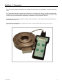
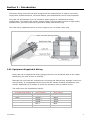
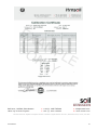
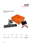
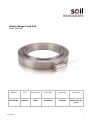
Strain Gauge Load Cell
User Manual
Man211
2.0.2
06/08/2014
Philip Day
Philip Day
Philip Day
Manual No.
Revision
Date
Originator
Checked
Authorised for
Issue
User Manual
1
Contents
Forward ............................................................................................................................ 3
Section 1 :
1.1
Introduction .................................................................................................. 4
Equipment Supplied & Wiring ............................................................................. 4
Section 2 :
Preparation ................................................................................................... 6
Section 3 :
Installation.................................................................................................... 7
3.1
3.2
Section 4 :
User Manual
Installation of Load Cells for Rock Bolts and Cable Anchors .................................... 7
Installation of Load Cells for Struts and Columns. ................................................. 7
Data Interpretation & Calibration Certificate ................................................. 9
2
Section 1 : Forward
This instruction manual, describes the technique required for the installation of centre hole load
cells.
It is important that the materials and equipment covered by this manual should be installed by
competent and suitably qualified personnel. They must READ AND UNDERSTAND the procedures
outlined in this manual before attempting installation of the equipment on site.
Soil Instruments will not accept for repair under guarantee, instruments/materials neglected or
mishandled in any way.
The techniques described are intended to serve as a general guide and may vary to suit
particular site conditions.
User Manual
3
Section 2 : Introduction
The Strain Gauge Load Cell has been designed for the measurement of loads in rock bolts,
single/multi-stranded anchors, structural beams, piles and between tunnel lining segments.
The Load cell Incorporates up to 16 resistance strain gauges in a Wheatstone bridge
configuration. The Gauges are equally spaced within a cell manufactured from a high quality
stainless steel, precisely machined to provide a stable load-bearing ring.
The Load cell is supplied as either an mV/V output or as a 4-20mA 2 wire loop.
2.01 Equipment Supplied & Wiring
Each Load cell is supplied with heavy gauge multicore, PVC sheathed cable to the length
specified by the user at time of ordering.
Although the Load cells are checked prior to leaving Soil Instruments, damage could occur
during transit. It is suggested that the load cells are visually checked immediately upon
receipt. Additionally it is prudent to check the operation using a readout device.
The cable cores are identified as follows:
4-20mA Loop Output
User Manual
mV/V Output
Wire Colour
Loop +
Supply +
Red
Loop -
Supply -
Black
Signal +
Green
Signal -
White
Ref +
Blue
Ref -
Brown
4
The supply Voltage for mV/V output Load cell can be from 2 to 15 Volts DC and the
4-20mA output Load cell should have a supply voltage of 12 Volts DC.
The Ref+ and Ref- are used to monitor the supply voltage at the Load cell to ensure correct
reduction of data into engineering units.
Soil Instruments recommends the use of its specially designed distribution plates to ensure
correct measurements from the Load cell are achieved.
Distribution plates should not be a smaller thickness than the Load cell and should not have
internal diameters smaller than that of the Load cell.
The abutment plate should be at least 20mm larger in diameter and not be smaller in
thickness than that of the Load cell or be mounted on a tube with dimensions which do not
fall within the internal and external diameters of the Load cell.
User Manual
5
Section 3 : Preparation
Warning:
Do not hit or strike the cell at any time with a hammer or other object.
A reading MUST be established on the unloaded cell prior to installation
and after loading has taken place.
Where a number of Load cells are to be installed it is essential that each Load cell and its
associated cable are accurately and effectively identified. A permanent marking system
should be adopted to ensure Load cells can be identified throughout their working lifetime
and this information safely stored for future reference.
It is essential that the load bearing surfaces above and below the Load cells are smooth and
flat, parallel and sufficiently strong to avoid significant distortion under load. Positioning and
alignment of the cells is critical to their performance.
The surface to which the Load cell is to be installed should be flat and perpendicular to the
anchor. If a steel abutment plate is provided on the structure face it should ideally be
beaded onto resin or cement to ensure complete contact between the structure and the
abutment plate with no voids beneath the plate. The area to be covered by the Load cell
assembly should be cleaned. In particular remove any paint and smooth out score marks
and rough imperfections with a file and abrasive paper.
Check that all the items for the installation are readily available i.e. Load cell, top and
bottom distribution plates, readout unit, calibration data for Load cell, anchor stressing
equipment and where necessary lifting equipment to support the weight of the Load cell.
The Load cell serial number and installation location should be checked and recorded.
Prior to installation, the cell should be stored close to its installation location to enable the
instrument to come into equilibrium with its temperature environment.
User Manual
6
Section 4 : Installation
4.01 Installation of Load Cells for Rock Bolts and Cable Anchors
4.0.1.1
Connect the readout unit to the Load cell and record the base (unloaded)
reading.
4.0.1.2
Carefully locate the bottom bearing plate, Load cell and top loading plate over
the anchor, followed by the anchor plate and stressing nut (for single strand
anchors) or anchor disc and collets (for multistrand anchors). Where
centralising recesses or buttons are provided on the plates, ensure that these
are correctly located. Suitable lifting tackle may be necessary in some
installations to support the weight of the Load cell, plates and stressing
equipment and to ensure correct alignment is maintained.
4.0.1.3
With the stressing equipment connected, slowly operate the hydraulic jack to
provide sufficient load to lightly hold the Load cell assembly against the
abutment plate. Check for alignment and concentricity of all the components
to ensure that the anchor load is applied in line with the axis of the load cell.
4.0.1.4
At this stage the Load cell should be read and the reading converted to
Engineering Units.
4.0.1.5
Loading of the anchor should be applied as per the values specified by the
Engineer. Readings should be taken at each load increments if required and
recorded.
4.0.1.6
Prior to locking off the anchor at the required working load a number of
loading cycles should be carried out to at least the working load to check the
performance of the Load cell and ensure that the anchor and Load cell are
correctly bedded in.
4.0.1.7
Most installations require the anchor to be tested to a maximum of 1.5 times
the eventual working load. The requirement for this operation should be
checked and agreed with the Engineer before the final locking off of the
anchor.
4.0.1.8
On completion of the installation the Load cell and bearing plates should be
heavily greased on all exposed surfaces.
4.0.1.9
The protective cover must be adequate to protect the Load cell from damage
as well as differential temperature changes. Reflective external surfaces and
internal insulation will help eliminate this effect.
4.02 Installation of Load Cells for Struts and Columns
4.0.2.1
Connect the readout unit to the Load cell and record the base (unloaded)
reading.
4.0.2.2
It is recommended that bearing plates are installed between the structural
members/reaction and the Load Cell. They will need to be positioned carefully
and where necessary fixed in place or supported. Suitable lifting tackle may
User Manual
7
be necessary in some installations to support the weight of the Load cell and
plates to ensure correct alignment is maintained.
4.0.2.3
With the Load Cell positioned where any Axial load will be transferred, slowly
move the structural member into place and generate some pre-load. (This
may be only the weight of the column or produced by applying a load via a
hydraulic jack).
4.0.2.4
At this stage the Load cell should be read and the reading converted to
Engineering Units.
4.0.2.5
Loading of the Load cell should be applied as per the values specified by the
Engineer. Readings should be taken at each load increments if required and
recorded.
4.0.2.6
Where possible a number of loading cycles should be carried out to at least
the working load to check the performance of the Load cell and ensure that
the load cell and bearing plates are correctly bedded in.
4.0.2.7
On completion of the installation the Load cell and bearing plates should be
heavily greased on all exposed surfaces.
4.0.2.8
A protective cover adequate to protect the Load cell from damage as well as
high differential temperature changes should be fitted to the installation.
Reflective external surfaces and internal insulation will help eliminate this
effect.
User Manual
8
Section 5 : Data Interpretation & Calibration Certificate
As with any monitoring system it is essential that all the factors that could possibly affect
the readings are recorded and taken into account such as atmospheric conditions and
construction activities.
The calibration certificate supplied with the Load cells is calculated with the calibration
information taken in units of mV/V or mA depending on the type of Load cell supplied.
The Load cell calibration certificate states a Slope (S) and Intercept (I) Value for the load
cell which are used to convert the Load cell readings into engineering values (kN)
MV/V Calibration
Readouts and data loggers where the output is in mV
Load (kN) = I + ( ( S * R ) / F )
Where:
S = Slope Factor from calibration certificate
R = The current reading in mV
I = The Intercept Factor from the calibration certificate
F = The current reference reading in Volts
MV/V Calibration
Readouts and data loggers where the output is in mV/V
Load (kN) = I + ( S * R )
Where:
S = Slope Factor from calibration certificate
R = The current reading in mV/V
I = The Intercept Factor from the calibration certificate
4 - 20mA Calibration
Load (kN) = I + ( S * R )
Where:
S = Slope Factor from calibration certificate
R = The current reading in mA
I = The Intercept Factor from the calibration certificate
User Manual
9
Bell Lane, Uckfield, East Sussex
t: +44 (0) 1825 765044
e: [email protected]
TN22 1QL United Kingdom
f: +44 (0) 1825 744398
w: www.itmsoil.com
Soil Instruments Ltd. Registered in England. Number: 07960087. Registered Office: 5th Floor, 24 Old Bond Street, London, W1S 4AW
User Manual
10