1
I
BuildaF.4,Sf Cassette
fnterface
Dr Robert Suding
ResearchDirector for Digital Group Inc
PO Box 6528
Denver CO 80206
This cassetteinterfacedoes not have a
!30% speedtolerance.The designrequires
!12Y and +5 V to run. A good quality
recordermust be used,along with excellent
quality tapes. Careful adjustments are
required.
So why use it? Well, it works! lt's
dependable.And it's fast. ln contrast,the
proposed BYTE standardcassetteinterface
runs at 300 Baud. A Teletype paper tape
r e a d s@ 1 1 0 B a u d . I h a v e 2 4 K o n m y
system. How long would it take me to
completely load my system (not including
any BootstrapLoaderoperations)?
T e l e t y p e@ 1 1 0 B a u d - 4 0 m i n u t e s5 8
seconds
ProposedBYTE standard@ 300 Baud 1 5 m i n u t e s1 s e c o n d
The systemto be shown in this articlehas
beenrunningfor almosta yearat 1100 Baud
(with an upper limit of 1750 Baud with
c r i t i c a lt u n i n g ) .
S u d i n gs y s t e m@ 1 1 0 0 B a u d- 4 m i n u t e s
6 seconds
Pastissuesof BYTE haveincludedseveral
articles on cassetteinterface proposalsand
circuits. I would suggestre-readingthese
a r t i c l e sY. o u w i l l f i n d o n e c o m m o ne l e m e n t .
Slow. lf you get the impressionthat I'm
i m p a t i e n ty, o u ' r er i g h t . l ' l l b e t y o u a r e t o o .
lmaginereading300 Baudfor 15 minutesto
discovera noise pulse had destroyeddata,
requiringre-reading.
Ugh!
Thus the proposedstandardof the BYTE
KansasCity conferencein 1975 hasa major
disadvantage:
The use of a redundantManchesterformat with a 1200 Hz low frequencycritically restrictsthe userto slower
for those
data rates.A relateddisadvantage
who use filters or phaselock loops as an
input detectionmethod is the fact that the
Manchestercode employs harmonicallyrelated frequencies; this leads to design
problemsin detectorsbasedupon frequency
d i s c r i m i n a t i otne c h n i q u e s .
The system shown in this article avoids
the above pitfalls. lt usesthe non-harmonically refatedtones of 2125 Hz - Mark and
2975 Hz - Space.The secondharmonicof
2125 Hz occursat 4250 Hz, well down on
the passbandof a 2975 Hz detector. Sufficient spaceexistsbetweenthe two frequencies to allow for reasonablerecorderspeed
discrepancies.The higher frequenciesinvolvedpermit increasing
the datarate.
Severalapproaches
are possiblein cassette
interfacing,as seen in past BYTE articles.
However, their emphasison wide cassette
speed tolerance made them slower. My
F U L Lw a v E D E r E c r o R s
lo1.
DS6
r N 4r 4 8
2975Hz
B A N D P A S SF I L T E R
os7
r N 4t 4 I
LIMITER
DS5
r N 4r 4 8
R34
47K
R53
rooK
R20
roK
-t2v
2t25Hz
FILTER
BANDPASS
3 POLE
L O W P A S SF I L T E R
ct2
+5 V
R38
470
t/2w
R36
roK
DGI
IN 4 8
t--
i7
R37
IK
R39
rooK
R42
5OK
R E A DO F F S E TA D J U S T
TO TTL
I N P U TP O R T
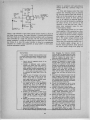
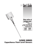
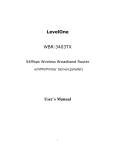
Figure 1: The schematic of the Suding cossette input interface os found in the Digital Group systems. This interfoce amplifies
ond clips the cassette output with limiting omplifier 1C34, discriminates the two dato frequencies (see table l) with bandposs
filters followed by full t4,vvedetecton, pases the detectedsignal through o 3 pole octive low possfilter, then converts the result
to o TTL level which is read by asingle bit input port, One example of softwore (seelisting 1) to drive this input interface usesq
programmed simulation of UA RT input algorithm; an octuol UART or ACIA devicecould be substituted if desired.
approachto "out of specificationcassette
s p e e d "i s - " p u t i t i n t h e s p e c i f i c a t i o no ,r
get a good recorder."Moreof that later.
Theory of Operation
The 1100 BaudDigitalGroup systemuses
the circuits of figures1 and 2. The cassette
receive circuitry detects the prerecorded
frequencyshift keyingand producesa "'l"
or a "0" output as a result of a detected
2125 Hz or 2975 Hz tone at the input. A
74'l operationalamplifier,1C34,is usedasa
in
clampedlimiter which preventsvariationS
cassette
amplitudefrom affectingthe detection process.The output of the limiter
shouldbe about .6 V peakto peak,roughly
a squarewave with rounded edgesof the
incoming frequency,constantin amplitude
of tape volume settingor minor
regardless
tape "dropout" problems,
Two bandpassactivefilters (1C35)then
amplify a tone five times when actually
tuned to their respective
frequencies
of 2975
Hz f or the top filter, and 2125 Hz for the
lower filter. The further off the tuned
frequencythe tone is, the lessamplification
t h e f i l t e r w i l l p r o d u c eT. h e g a i n ,b a n d w i d t h ,
and tuned frequency are set by the three
resistorsand two condensers
in each filter.
Each filter may be exactly tuned to frequency by carefully setting the variable
resistancevalue (which may be either a
potentiometeror selectedfixed values).
Full wave active detectors produce
rectified full wave pulsesat the summing
junction, pin 5 of 1C37.The 2975 Hztones
are rectified to a positivevoltage,and the
2125 Hz tones are rectified to a negative
voltage.As receivedtonesdepartfrom either
exact frequency, a value less positive or
47
)
+5V
tR4l
5K
Rt5
S P A C EA D J
( 2 9 7 5 H z)
R40
3l.rlf-
TO CASSETTE
MICROPHONE
I N P U To R . A U x .
J2
oz2
5V ZENER
(TYPICAL)
Rr6
220
|/ 2 W
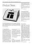
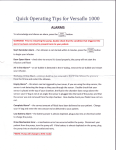
Figure 2: The schemotic of the Suding cassetteoutput interfoce os found in
the Digital Group systems. The output interface is a simple audio frequency
shift keyer mode up of a 566 voltage controlled oscillator with two frequency
states controlled by a single TTL dato line. The TTL level which drives the
output modulator is a single bit derived from an output port, The software
(see llsting 2) to drive this output interface is shown os a progrommed
simulotion of a UART output olgorithm; on octual UART or ACIA device
could be substituted if desired,
Tune Up Notes
The cassette interface must be carefully tuned
to achieve proper performance. Carelesstuning has
been the most frequent cause of cassette system
failure.
1. Plug in the six integrated circuits of the
cassette interface.
2. Connect a calibrated audio oscillator
between the limiter input and ground. A
digital frequency counter driven by the
audio oscillator is highly recommended. The
oscillator should cover the desired range of
2 - 3 kHz,with a sinenave output of .5 or
so, although the precise level is not at all
critical.
3. Apply +5 and 112 voltagesto the circuit.
Measure the output at pin 6 of the 741
limiter (lC34l with an oscilloscope.The
wave shape should be a rounded square
wave of about .6 V peak to peak.
4. Set the audio oscillator to 2125 Hz. Measure
the output at pin 1 of the 5558 active
bandpass filter. Slowly turn R25 until the
signal peaks. Be sure that you are peaking at
2125 Hz. not a harmonic. Vary the oscillator frequency a few decades to insure
2125 Hz is the tuned frequency.
5. Similarly, set the oscillator to 2975 Hz and
measure the output at pin 7 of the 5558
(1C35). Slowly turn R26 until the signal
peaks. Vary the oscillator to insure a 2975
Hz peak.
6. Measure the detected voltages at pin 5 of
1C37. When the oscillator approaches 2125.
the voltage should go negative. When approaching n75, rhe voltage should go positive. Trouble in this area would most likely
be caused by reversed or defective diodes, or
shorts between adjacent lines.
7. Measurethe voltage at the cathode (bar) end
of the output clamping germanium diode
/t8
8.
9.
10.
11.
12.
13.
negative is produced until approximately
midway (2550 Hz) a summedvoltageof 0
results.
A three pole lowpassactive filter then
removesthe remainingtracesof pulsating
DC from the summedsignalwith almostno
effect on the data pulsesup to a speedof
1000 bits per second.lf lower data rates
were to be utilized, an improvedsignalto
n o i s er a t i o c o u l db e o b t a i n e db y m u l t i p l y i n g
t h e v a l u e so f C 1 2 , C 1 3 , a n d C 1 1 b y t h e
reciprocal of the data rate ratio. Table 1
shows some component values for alternativefrequencydesigns.
The final receiversectionis a 741 operational amplifier,1C38,connectedas a slicer.
This operationalamplifier detects whether
the voltageat its pin 2 is positiveor negative
with respectto the constantvoltageat its
p i n 3 . T h e o u t p u t v o l t a g ew i l l t h e n s w i n g
e i t h e r t o n e a r l y - 1 2 Y o r t o n e a r l y+ 5 V .
Notice that this operationalamplifierhas+5
as its positive supply voltage, pin 7. A
forward biased germaniumdiode prevents
the actual output voltagefrom going less
(G1). Sweeping the frequency between
2125 and 2975 Hz should result in a clean
voftage iump somewhere between 2125 and
2975 Hz. Measure the output swing to
insure that it does not exceed +5, -.3 V.
Remove the audio oscillator and short input
connector Jl temporarily to ground. Measure the output at pin 6 of 1C34. A stable
condition (no oscillationl should be seen.
Connect the oscilloscope to the cathode of
G1 again. Adiust the balance potentiometer
(R42) so that the output voltage is a
negative level. Slowly turn the potentiometer until the output voltage jumps to a
positive level and leave the setting at this
point.
Disconnect the temporary jumper from the
input connector and reconnect the audio
oscillator. Perform step 7 again. The crossover threshold should be close to 2550 now.
lf all proceeds well at this point, the cassette
interface is ready to receive data.
Connect the oscilloscope to pin 4 of the
5 6 6 v o l t a g e c o n t r o l l e d o s c i l l a t o r ( 1 C 3 3 ) .A
triangular hraveoutput should be seen.
Connect a temporary jumper between the
TTL input going to DSI and +5 V. Connect
a frequency counter to pin 3 of the VCO
(1C33). Adlust potentiometer R41 for a
resultant output frequencv ot 2125 Hz.
Remove the lumper from +5 V and connect
's
the lumper from DS1 input to ground.
This time adjust R4O lor 2975 Hz output.
Remove the jumpers, and you are ready for
final tune in the driving circuit. Connect the
cassette interface to the driving output port,
and program the driving processor to send a
TTL high level ("1") output to the cassette
interface. Adjust R41 to 2125 Hz. Then
have the processor send a "0" level. This
time adjust R40 for ?975 Hz output. The
cassette interface is now ready for use,
t h a n = - . 2 V , s o t h a t v a l i d T T L l e v e l sa r e
not exceeded.An offset adjusting potent i o m e t e ra l l o w st h e o u t p u t t o b e p l a c e di n a
" M a r k H o l d " c o n d i t i o nw h e n n o t o n e i n p u t
is beingdetected.
The cassetterecordingsection (figure2)
usesa singleintegratedcircuit,a 566 voltage
c o n t r o l l e do s c i l l a t o r ,1 C 3 3 . A l o g i c l e v e l
from the computer'soutput port controls
the resultantaudio frequencyoutput to the
cassetterecordermicrophoneinput. A high
i n p u t ( " 1 " ) p r o d u c e sa 2 1 2 5 H z o u t p u t ,a n d
a l o w i n p u t ( " 0 " ) r e s u l t si n 2 9 7 5 H z . T h e
output wave shapeis a symmetricaltriangular wave.Shouldthe userobjectto usinga
triangularwave,a more nearlysinewavecan
be obtainedby connectinga pair of backto
b a c k 1 N 9 1 4d i o d e sb e t w e e ng r o u n da n d t h e
output sideof the couplingcapacitorC5.
Exact values and high quality componentswill result in a trouble-freevoltage
controlledoscillator.The 47 K (R17) resistor
i n s e r i e sw i t h t h e o u t p u t i s a t y p i c a lv a l u et o
b e u s e dw h e n c o u p l i n gt o t h e l o w l e v e l ,l o w
i m p e d e n c ee x t e r n a l m i c r o p h o n ei n p u t s o f
most cassetterecorders.Usingthe "AUX"
input of your cassetterecorder generally
givesbetterresults.
Construction
The cassetteinterfaceis available
asa part
of a printed circuit board kit from the
D i g i t a lG r o u p . T h e p r i n t e dc i r c u i t b o a r d i s
sharedby a televisiondisplay circuit to be
d e s c r i b e idn t h e n e x t a r t i c l ei n t h i ss e r i e sA.
kit of the cassetteinterface only is also
availablefrom the Digital Group for 930,
w h i c h i n c l u d e sa l l p a r t s a n d t h e p r i n t e d
c i r c u i t b o a r d . T h e e x p e r i e n c ebdu i l d e rc a n
b u i l d t h e c i r c u i t i n a n e v e n i n go r t w o b y
h a n dw i r i n gc o m p o n e n tosn s t a n d a r d
.1 inch
grid Vectorboard.All the circuitry can be
containedin an areaof approximately3 inch
b y 5 i n c h ( a b o u t8 c m b y 1 3 c m ) .
Be sure to use only high quality components,particularlyin the activebandpass
filters and voltage controlled oscillator.
Some strange"frequency jump" problems
havebeentracedto surplus566swhich were
temperaturesensitive.Lay out the receive
circuit to avoid feedbackpathsfrom output
to input, particularlyin the limiter, active
bandpassfilters, and slicer areas.Different
o p a m p s c o u l d b e u s e d ,b u t m a y r e s u l ti n
instability or degradationof final performancedue to suboptimization.
VIDEO
TERMINAL
fon youR
ATTAIR
OR
IMSAI
VIDEO
TERMINAL
INTERFACE
Connects
lo standardTV monitor(or modrliedreceiver)
lo disolav16 linesol 64 or 32 characlers
in a 7 x I
matrix Charact€r
setincludes128uooerandlowercase
ASCIIcharacters
and 64 graphiccharacters
lor ploning
48 x 64 (128wilh memoryoption)array Textandgraphics may be mixedon the samescreen 8.bil keyboard
in0utoortis 0rovidedCharacters
are stor€din lhe onboardmemoryand maybe reador wrinenby lhe computer Cursorcontroltexledilingandgraphicssottware
rs Included Fully compaliblewith Allair and IMSAI
Socketsincluded
W l / 3 2 3 2 c h a r a c l el irn e $ 1 8 50 0 k r l
Wl /64 64 character
line $210 00 kil 528500 assd
ANALOG
INTERFACE
inlerlacelor a CRTgraphicsdrsplayor X-Y
Compiete
oloner Provrdes
8 channelsol sottware'conlrolled
A/D
1 or 2 channels
conversron
ol analogoulputwith 10-bil
0 . 1 0 vo r t 5 v o u l ) 6 b i t so t l a t c h e d i g i t a l
r e s o l u l i o( n
oulpul and I analogcomparators
included
lor
Soltware
A/D conversron
by successive
approximation
andlracking Sockelsincluded
ADA/I 1 analoo
g u l p u t $ 1 4 50 0 k i t
A 0 A / 2 2 a n a l o og u r p u t s$ 1 9 50 0 k i t $ 2 5 50 0 a s s d
SEETHESEAND OTHER
PRODUCTSAT THE FOIIOWING
COMPUTERSTORES
(213)478-3168
THE
COMPUTER
STORE
L o sA n g e l e sC,A
(714t633.1222
T H EC o M P U T E
h tRA R T
o r a n g eC, A
COMPUTERS
& STUFF
1415\278-4720
SanLorenzo,
CA
( 8 0 1) 3 7 7 - 7
COMPUTERS
& STUFF
1 17
Provo,Utah
) 31-1691
C t ) M P U TS
EY
B S T E MCSE N T E R ( 4 0 4 2
A t l a n t aG, A
( 4 15 )9 6 9 - 5 4 6 4
BYTESHOP
MountaV
i ni e w C
, A
D E A L EI R
NOUIRIE
I NSV I T E D
Modifying Your CassetteRecorder
It is very helpful to listen to the data
from the cassetteso that the beginningof
the data burst may be detected,as well as
A l l p n c e sa n d s p ! c i l r c a t r o nssu D l r c t o c h a n g ar i l h o u l n o l r c r P n c a sa r c U S A0 n l y
s dd6 . rrlls ler Add 5'" rhrpp'ng hrndlng .nd 'n3ur.nc.
Crll fesrdenre
POTYMORPHIC
SYSTEMS
7 3 7 S K e i l o g g , G o r e r a ,C A 9 3 0 1 7 [ 8 0 5 1 9 6 7 - 2 3 5 1
Low Filter
Hioh Filter
vco
Low Pc Filter
R21
R24
R25
R22
R23
R26--C13
C12
C14- R 1 2 R 1 5
.01
.015 2 . 7 k 1 . 3k
.015 470 k 2.7 k
2125-2975H2
1lfl1 Baud
12Oo240/|Hz
3(XfBaud
(Simplel
6.8 k
68 k
938
4.7 k
47 k
697
6.8 k
68 k
4173 4.7 k
47 k
1162 .fl)56 pF
.01
12U}240OHz
30OBaud
(Correctl
12k
120k
1668 5.6 k
56 k
906.015pF
. 0 3 3 . O 4 7 470 k 2.7 k
27252295
1(X)Baud
(Simple)
6.8k
68k
938
4.7 k
47 k
1301 ,.0056pF
.01
.O15 47 k
2.7 k
272U2295
1(X)Baud
(Corectl
36k
360k
156
2t k
270k
179
.1
.15
2.7 k
.0056 rrF
.056pF
47 k
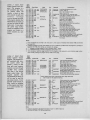
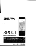
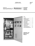
r means that the valuo so indicated is the typical calculated value. The precise value is dependent on
compon€nt
tolerance.
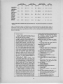
Table l: Theoretlcolvoluesof componentsfor alternate frequencles.Thls toble gives valuesof
componentsto be used with the circuits of figuresI ond 2 in order to mokethls cossettelnterface
work with severololternotespecificotions.Seethe text for o deflnitlon of the vorlouscommentsat
the left of the toble,
Potential Troubles
Knowing about potential problem areasis a
first step to minimizationof their effects.Troubles
seem to break down into srx classes,
. Cassette recorders and the cassettesused: A
marriagebetweenyour$100Omicroprocessor
and
junior's $20 cassette recoider, which has been
using 3@ oassettesfor the last five years, will not
produce happy offspringl I have been using a
Superscope
Gl04 for the pastyear,and can report
no failures except for defective cassettetapes,The
GlOl has severalattractivefeatures.Besidesthe
usual conveniencessuch as index counter, cuing,
etc, it hasa variablereadbackspeedcontrol, dandy
for out of spec cassettesfrom friends, Inside,
anotherspecialmotor speedcontrol potentiometer
is located near the speakerwtrich allows precisely
setting the record/write speed. Ouality control
seemsgood overall, and the list price of $120
(cheaper at discount storesl is $orth the investment. Don't r rasteyour money on cheapcassettes.
Sony Low Noise C45s havebeengenerallygood.
Some $2 - 94 Data Certified Cassettesare
superior, but not needed.
. Microprocessor caused problems: Some
microprocessor
designswill not work directly with
this interface system. This interface was designed
to be connocteddirectly to a singlebit lo port,
with the processorhandlingall of the bit timings
through timing loops. lf your processormust
periodically catch its breath for such things as
dynamic memory refreshing,you may be unableto
directly use the "Software UART" system.What a
shamel However,a hardware UART will permit
usingthe systemevenwith a systemof this nature.
o
Cabling problems: lt is possibleto connect
your cassetterecorderswith the read and write
cables reversed. Enough crosstalk from the write
line to the read limiter existed to give the
appearanceof data being read, but so many errors
resulted that the programmingwould not run.
o Tuning problems: Circuit tuning is the most
common problem. Carefully tune the activef iltersl
o CassetteCrashes:Cassettedamage is frequent
50
on tapes which have always worked before, but
now mysteriouslyfail. The most commoncauseof
this is removing a cassette from the recorder
without completelyrewinding.The exposedoxide
then getsdamaged,and is no longerusable.
o Miscellaneous
circuit problems:
Defective level output from cassetteread limiter,
1. None at all: Checklor t12 V to 1C34,and
rc34.
2. Too high output level: Diodes (DS4 and
DSSI open, or one is reversed.
Bandpass
activefilters don't filter.
1. Off frequency
2. Bad 5558
3, Check for shorts or out of tolerancecondensersC8, C9, C10, or Cl 1. Diskceramics
area "no.no" in tuned circuits.
4. Resistorsimproperly wired or inserted.
Full wavedetector does not work asdescribed:
1. Diodesopen, reversedor shorted.
2. Defective1C36.
Low passactivefilter fails to work:
1. Shorted or out of tolerancecondensers.
2. Defective 1C37.
Output slicer(lG38l failsto produceTTL levels:
1. Reversed,open or not Gormaniumdiode at
DG1.
2, Too heavily loaded output. This circuit
should drive no more than one TTL load
(standardfor most lO portsl,
VCO won't oscillate.
1. Defective566 (1C33).
2. Shorted condenserC6,
VCO hasparasiticoscillation(highfrequency):
1. C7 not connected.
2. Defective566.
3. C6 is open, producing a very high frequency.
VCO won't tune to frequencyor stay there:
1. Out of toleranceor defectiveC6. You really
didn't usea disk ceramichere,did you?
2. Defective566.
3. Non-TTL levelsusedto drive VCO.
4. DefectivepotentiometersRzlOor R41.
5. DSl or DZ2 reversedor defective,
hearing the end of the data. When the
cassette read cable is plugged into most
cassetterecorders'earphone
output jack, the
output
is
usually
cut
off. However,
speaker
since a closed circuit jack is all that is
involved,a quick solution is to connecta
jumper on the jack so that the speakeris not
disconnected.Even better, use a 1O0 ohmly'+
watt resistorinsteadof the jumper,and the
data howl won't be so loud. A 10 ohm,/+
watt resistorfrom the amplifier lead to jack,
to the jack frame will prevent potential
damageto the output driving transistor(s).
and Applications
AlternativeFrequencies
The cassetteinterfacedesignmay be used
with the proposedBYTE standardshould
you so desire. Table t has appropriate
component valuescalculatedfor twc alternative possibilities:the simple way (less
desirable)and the "right way". The simple
way permitsusinga switch on the bandpass
active filters to selectthe frequencypairs.
The right way involvessettingthe circuit to
the optimal values,and usingseparateinterfacesfor eachfrequency pair.
Amateur radio (ham) radioteletype
(RTTY) generallyuses 2125 - 2295 Hz
frequencyshift keyingfor 170 Hz shift. The
existing cassetteinterface can be used by
"straddle tuning," but improved perfcirmance may be obtained by selectinga
secondR26 which will tune the highfilter to
2295. The cassetteread cable may then be
attached to the short wave receiverand the
programmedas a radiotelemicroprocessor,
type video terminal, which can replacethe
noisy Teletype machine. Of course, a
cassette interface specifically designedfor
this 170 Hz shift at 100 WPM will give
superiorperformanceunder marginalconditions.
The cassetteinterface may be used as a
stand alone radioteletypeterminalunit and
audio frequencyshift keyingif desired,and
w o r k sq u i t en i c e l yi n t h i sa p p l i c a t i o n .
Software
I would suggestusingsoftwarefor your
cassette
readand write timings.Sample8080
softwareis includedas listing 1. Timingsat
focations
<0>/116,<0>1133, <0>1241,
and10)1260arebased
on an 8080system
with a 500 ns T time and no wait states.
Slower systemswill requireproportionately
decreaped
loop timings.
A UART could be used insteadof the
"software UART" systemshown. However,
severaldisadvantages
arise. First, a slightly
gteater cost and complexity. More important, however, is a degradation in total
If you want a microcomputer
wtth all of these standard featuJGS...
. 8080MPU (The one
with growing software support)
. 1024 Bvte ROM
( W i t h m d x i m u mc a pacity of 4K Bytes)
. 1024Byte RAM
(With maximum
capacityof 2K
Bytes)
. TTY Serial I/O
. E I A S e r i a ll / O
. 3 parallel/O's
. ASCII/Baudot
t e r m i n a lc o m patibility with TTY machinesor video units
. M o n i t o rh a v i n gl o a d ,d u m p , d i s p l a yi,n s e f t
andoo functions
. Complete with card
con nectors
. Comprehensive
User's Manual, plus
Intel 8080 User's
Manual
. Completelv
factory assembled
and tested-not
a kit
. Optionalaccessories:Keyboard/video
display,audio
cassette modem
interface, power supply, ROM programmer
and attractivecabinetry . plus more options
to follow. The HAL ltlCEM.8O8O.
S375
...then let us send you our card.
HAL CommunicationsCorp. has
b e e n a l e a d e ri n d i g i t a lc o m m u n i cationsfor over half a decade.
The MCEM-8080 microcomouter
shows just how far this leadership
h a st a k e nu s . . .a n d h o w f a r i t
can take you in your applications.
That'swhy we'd like to send
you our card-one PC
board that we feel is the
best-valued,most complete
microcomputeryou can buy. For
detailson the MCEM-8080, write
today.We'll also includecomprehensiveinformationon the HAL
DS-3000 KSR microprocessorb a s e dt e r m i n a l ,t h e t e r m i n a lt h a t
gives you multi-codecompatibility,flexibilityfor future
c h a n g e s e, d i t i n g ,a n d a
c o n v e n i e n tl,a r g ev i d e o
displayformat.
IIAL Communlcatlons Corp.
Box 365, 8O7 E. Green ttreet, Urbana, Illinois 61801
Telephone (217 | 367 -7373
Listlng l: Stand Alone
Split
Octal
SudlngCasette lnput Pro
Address OctalCode
grom, Thls program ls a
<0>/100
xxx xxx
self contalned dato trons- <0>/103 041
021 010 0(x)
fer routine whlch will
<0>/106 333 001
tronsfer o block of doto <0>/110 346 001
<0>1112302 106 <0>
from cossetteto spllt octal +<0>/115
006 300
memory
l o c a t i o n s < 0 > / 1 1 70 0 5
<0>1120302 117 <0>
xxxf xxx throughyyyl000.
<0>1123333 001
Thlsprogramasumesthot
<0>11253/t6 001
<0>11272o2
MEMTOCAS(seelistins2)
0 > / 1 3 00 1 7
vvasusedto createthe tope <
<0>113112t
*<0>1132
belng read. A morc gener006 200
<0>/134 005
olly useful input focility
<0>/135 302 134 <0>
vwuld be modelledon thls
<0>/140 035
program and llnked to o
<o>t141 302 123 <0>
<0>114/ 162
system monitor as o sub
<0>/145 043
routlne.
<0>1146174
Label
Op.
Operand
CASTOMEM
STARTBYT
SYNCHLOO
LXI
LXI
lN
ANI
JNZ
MVI
DCR
JNZ
lN
AN |
ADD
RRC
MOV
MVf
DCR
JNZ
DCR
JNZ
MOV
INX
MOV
CPI
JNZ
HLT
H,xxx/xxx
D,000/000
1
1
SYNCHLOO
8,300
B
WSYNCH
1
1
D
WSYNCH
GETDATA
WDATA
,t <0>1147376 yyy
<0>/151 302 103 <0>
<0>/154 166
D,A
B2OO
B
WDATA
E
GETDATA
M,D
H
A,H
yyy
STARTBYT
Commentary
Load starting address in HL pair;
Load E, clear D;
Port 1 bit 0 read for input;
Maskall but bit 0;
lf not srart bit then reiterate loop;
Time delay to middle of first data bit*;
Decrembnt synch wait count;
lf not done then keep waiting;
Read port 1 bit 0 again;
Mask all but bit 0 again;
Sum old bits wirh nbw bit;
Rotate new and old into next position;
Save result back in D;
Time delay between bits;
Decrement data wait count;
lf not done then keep waiting;
Decrement data count loaded at 0/103;
lf not done then repeat for next biu
Save received data in memory;
Point to next available location;
Move higfi order addressto A for end check;
Has high order addressreached end?
lf not then reiterate for next byte;
End input;
Notes:
a
a
O
Input is assumedto be wired to bit 0 of port 1, from output of lC38 pin 6 via resistorR38 and shunted
by diodeDG1.
Loadingproceedsfrom split octal addressxxx/xxx to addressyyylOOO.Enterthis programby jumpingto
location<0>/10O after setting up constantsof address.
"*" indicatesa timing constantfor the "software UART" inputs.
" v " indicatesthe end of transfercomparisonmentionedin text.
(0) indicatesan arbitrary pagBlocation for this program,to be replacedby a real memory pagenumber
when actuallyloadingthe programat byte 100 of somepage.
Split
Llstlng 2: Stand Alone
Octal
Sudlng Cosette Output
Address
OetalCode
Label
Op.
Operard
Commentary
Program.Thlsprogramls a
<o>120f) 04l xxx xxx MEMTOCAS LXI H,xxx/xxx
Load startingaddressin HL pair;
self contoined dota trons- <o>1203 076 001
MVI A,1
Start port output in high state;
<0>/205 323 001
OUT 1
Sendinitial stateout;
fer routlne uhlch wlll
<o>1207 026 012
MVf D,012
Outer leaderdelaycount;
tronsfer o block of dota
<o>1211 006 377
LEADERsS MVf 8,377
Outer leaderdelay loop return;
octol
memory
from spllt
<o>1213 016 377
LEADERSX MVf C,377
Middleleaderdelay loop return;
<0>/215 015
LEADERSY DCR C
Inner leaderdelay loop return;
locotlonsxxxf xxx through
302 215 <0>
JNZ LEADERSY lf inner loop not done then rerterate;
yyyl000 onto co$ette <o>1216
<o>1221 005
DCR B
Middleleaderdelaycounq
tary ofter a flve second <o>1222 302 213 <0>
JNZ LEADERSX lf middle loop not done then reiterate;
DCR D
Outer leaderdelaycount;
leoder output deloy, Thls <o>1225 o25
<o>1226 302 211 <0>
JNZ LEADERSS lf outer loop not donethen reiterate;
progrom ossumes that
* Upon reachingthis point, 5 secondsof mark (high)statehave
CASTOMEM(seellstlng l)
*
beenoutput to the cassetteinterface.
wlll be used to rcad the
*
tapebelngcreated.A more
<o>1231 0 1 6 0 1 1
BYTEOUT
MVI C,011
Defineoutput bit count (decimal9l;
<o>/233 257
XRA A
Clearcarry (startbit levelis 0);
generollyuseful output fa<o>l2u 176
MOV A,M
Move current byte to A;
clllty would be modelled <o>1235 o27
RAL
Rotatebit into position (carry=Of irst);
<o>1236 323 001
WNEXBIT
Sendcurrent LSB to output port;
OUT 1
on thlsprogromand llnked r<0>1240
006 2m
MVI 8,200
Time delay betweenbits;
to o systemmonltor os o
<o>1242 005
WOUTLOOP DCR B
Decrementdelaycounu
subroutlne.
<o>1243 302 242 <O>
JNZ WOUTLOOP lf time left then reiterate;
t
<o>1246 037
<o>1247 0 1 5
<o>1250 302 236 <0>
<0>/253 076 001
<0>/255 323 001
*<o>1257 006 377
<o>1261 (x)5
WlBDELAY
<o>1262 302 26r <0>
<o>/265 043
,<0>/266 174
,t<o>1267 376 yyy
<o>1271 302 231 <0>
<o>1274 166
RAR
DCR C
JNZ WNEXBIT
MVI A,0Ol
OUT I
MVf 8,377
DCR B
JNZ WIBDELAY
INX H
MOV A,H
CPI yyy
JNZ ' BYTEOUT
HLT
Rotatenew bit into position;
Decrementoutput bit count;
lf data left then reiterate;
Stop bit sratedefined
then sent out to port;
Stop bit valueseu
Decrementstop bit counter;
lf time left then reiterate;
Incrementmemoryaddress;
Movehigh order addressto A for end check;
Hashigh order addressreachedend?
lf not then continueoutput process;
End output;
Note:
. Output is assumedto be wird from bit 0 of port I to DSl in figure 2.
o Seenotesto listing 1 for listing con\rentions.
52
system flexibility. The "software UART"
allows the timing constantsto be dynamically modified (if desired)by detectingthe
variationsin the stop bit timing, thereby
compensatingfor wow and flutter. Digital
integration of the incoming data bits is
possibleby settinga registerto octal 200 at
t h e b e g i n n i n go f e a c hb i t t i m e . D u r i n gt h e
b i t t i m e , r e p e a t e ds a m p l i n ge i t h e r a d d so r
subtractsfrom the register(dependingon
whether 1 or 0) and a "branch minus"
instructionsystemeffectivelyeliminatesreceive problems. This digital integration
d e t e c t i o ni s u t i l i z e d b y t h e D i g i t a lG r o u p
Z-80 cassettereadsoftware.
Versionsof this "software UART" system havebeenwritten for 8008, 8080,Z-80,
6502,and6800. All wcrk satisfactorily.
Operation
This cassettesystem is utilized by first
turning on the cassetterecorderand waiting
until the lower tone 5 secondleadertone is
heard. At this point, restartthe systemto
the beginningaddressof the "Cassetteto
Memory" software.
Cassettewriting is accomplishedby restartingthe systemto the beginningof the
"Memory to Cassette"programming.
Be sure
to set the appropriatestart and stop addressesprior to beginningthe reador write
operations.The monitor programsin the
variousDigitalGroup systemsautomatically
set the start and stop addresses.
The check
m a r k si n t h e l i s t i n g( / ) i n A i c a t et h e p o i n t s
where start and stop addresses
may have to
be modified.
The softwaremay be adlustedto run at
different dataratesby changingthe valuesat
the addresses
mark with an asterisk(*). Note
that the constantsat (0)i 133 and <0>1241
are the same.The constantat (0)/1 16 is
50% greaterand the constantat10)p6Ois
twice the valueof the constantat1oll241 .
Summinglt Up
This cassette
interfacerepresents
a simple
but fast and dependableway to store programsand data for the serioushobbyist.lt
doesnot seekto be all thingsto all users,but
a n u m b e ro f a p p l i c a t i o ncsa n b e r u n u s i n g
the same basicdesign.The detail interface
design has independence
from other comp o n e n t s i n t h e s y s t e m ,a l l o w i n g v a r i o u s
processorsto use the same cassettesystem
(with appropriatesoftware).r
UNBETIEVABTE!!!!!
TheIntecolor@
8001Kit
A CompleteI COLOR
hteillgent
cRTTermlnalKlt
s1,595
"Complete"Means
. 8080CPU. 25 Linex 80 Character/Line
. 4Kx8 RAM / PROMSoltware
. Socketsfor UV ErasablePROM. 19"ShadowMaskColorCR Tube
. R5232 l/O . Socketsfor 64 SpecialGraphics. SelectableBaud Ratesto
9 6 0 0B a u d. S i n g l eF b c k a g e S
. C o l o rM o n i t o r .A S C I IS e t
. Keyboard
. B e l l. M a n u a l
And you alsoget the Intecolor'80019 SectorConvergenceSystemfor
e a s eo f s e t u p ( 3 - 5m i n u t e s ) a nsdt a b i l i t y .
AdditionalOptionsAvailable:
. Roll. AddrtionalRAM to 32K . 48 Linex 80 Characters/Line
. LightPen
. LimitedGraphicsMode . BackgroundColor. SpecialGraphicsCharacters
. Games
I S C W I L L M A K EA B E L I E V E RO U T O F Y O U .
@
N
N
( n o) I n t e c o l o r8
S e n dm e ' 0 0 1 k i t s a t $ 1 , 3 9 5p l u s$ 1 5 0 0 s h i p p r n gc h a r g e se a c h
Enclosed
i s m y D c a s h r esr c h e c k ,! m o n e yo r d e ( ! p e r s o n aclh e c k *
, l S 3 5 0d e p o s i t / k if to r C O D s h i p m e nfto r $
NAME-
ADDRESSCITY-
STATE-
ZIP
'Allow 8 weeks clearance on
Dersonal checks
Delivery 3G60 days ARO