1
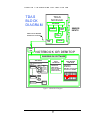
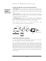
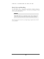
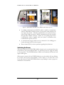
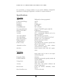
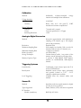
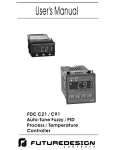
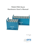
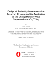
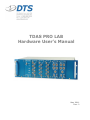
TDAS PRO LAB
Hardware User’s Manual
May 2011
Rev. 2
Table of Contents
Technical Overview ........................................................................................2
TDAS PRO LAB Rack Systems .....................................................................4
Basic Care and Handling................................................................................5
Unpacking the System ....................................................................................6
Connecting the Cables....................................................................................6
Connecting Communication and Trigger Cables ...................................................... 6
Switching On Power...................................................................................................... 7
Sensor Connector Options..............................................................................8
Wiring Sensor Cables ......................................................................................8
Calibration Techniques ..................................................................................9
Voltage Insertion............................................................................................................ 9
Shunt Calibration............................................................................................................ 9
General Care ................................................................................................. 10
TDAS Hardware Calibration ........................................................................ 10
Specifications ................................................................................................ 12
Calibration ..................................................................................................................... 13
Analog-to-Digital Conversion .................................................................................... 13
Triggering Systems ....................................................................................................... 13
Sensor ID ...................................................................................................................... 13
Power Requirements and Features ............................................................................ 14
Environmental .............................................................................................................. 14
Physical .......................................................................................................................... 14
Control Software .......................................................................................................... 14
i
C H A P T E R
1 — I N T R O D U C I N G
T H E
T D A S
P R O
1
L A B
Chapter
Introducing the TDAS PRO LAB
Each TDAS PRO LAB module is a highly advanced data
recorder that is also easy to use.
C
ongratulations on choosing a TDAS PRO LAB data recorder for your data
collection project! We are proud of our product and we want you to be
completely satisfied with your purchase. The TDAS PRO LAB is the latest
evolution of our original TDAS product that has won praise for value and
reliability. The following information will introduce you to the inner workings of the
TDAS PRO LAB.
Technical Overview
Each 8-channel
module functions
as a complete,
standalone data
recorder with
integral microprocessor,
adaptive signal
conditioning,
excitation
sources, A/D
circuitry, and data
memory.
TDAS PRO LAB hardware is a standard 19-inch, rack-mounted system commonly
used for stationary laboratory data collection. Each 8-channel module functions as a
complete data recorder with integral microprocessor control, adaptive signal
conditioning, excitation sources, A/D circuitry and data memory.
TDAS PRO LAB functions are set-up using an IBM-compatible computer. Once the
computer initializes the system, it can be disconnected and the module will collect data
with no additional support. After the test, data stored in each module is downloaded
to the PC hard drive in binary format. Once on the hard drive, the binary data files are
then unpacked for viewing and post-processing.
There are no potentiometers to adjust because hardware settings are performed
completely under software control. Every time a data collection task is initiated, the
software runs a thorough calibration check on each measurement channel.
Appropriate gains are set, sensor offsets are zeroed and anti-aliasing filters are set.
Sensor inputs are through connectors located on the front of each TDAS PRO LAB
module. See Chapter 5−Configuration/Specifications for your specific connectors and pin
assignments.
2
C H A P T E R
1 — I N T R O D U C I N G
T H E
TDA S
BLO CK
DI A GRA M
T D A S
L A B
TDA S
M O DULE
PROCESSOR
SIGNAL
COND.
MEMORY
SERIAL LINK NOT REQUIRED
DURING DATA COLLECTION
SENSOR
INPUTS
A/D
CONV.
SERIAL
LINK
SERIAL
LINK
P R O
TRIGGER
N O TEBO O K O R DESKTO P
WINDOWS GUI SOFTWARE
TEST SETUP
DATA
COLLECTION
TEST SETUP FILE (.TSF)
MODULE 1
RATE &TIME
SENSOR CHANS
.SIF
.SIF
.SIF
MODULE 16
RATE &TIME
SENSOR CHANS
SENSOR
INFORMATION
FILE
- DESCRIPTION
- CAL FACTOR
- GAIN FACTOR
- MODEL
- SERIAL NO.
CHOOSE .TSF
VERIFY SETUP
WAIT FOR TRIGGER
COLLECT DATA
DOWNLOAD DATA
.SIF
.SIF
CALCULATED
CHANNELS
MULTIPLY,
INTEGRAL,
HIC, ETC.
Figure 1: TDAS Block Diagram
3
POST PROCESS
VIEW DATA
SCALE DATA
FILTER DATA
PERFORM CALCULATIONS
PLOT DATA TO SCREEN
C H A P T E R
1 — I N T R O D U C I N G
T H E
T D A S
P R O
L A B
Each TDAS PRO LAB module contains the following subassemblies:
Each TDAS PRO
LAB module is a
completely
autonomous data
collection system.
A System Board that contains eight channels of adaptive signal conditioning, voltage
insertion calibration functions, filtering, A/D, and triggering circuitry. Hardware antialiasing filters are set under software control based on user-selected data sampling
rates.
A Processor Board that is very similar to most PCs in that it has a microprocessor,
program storage, RAM, and communication links. The internal processor uses digital
I/O channels to control all module functions.
An Auxiliary Board that contains power control circuitry, battery charging/status
circuitry, software-programmable isolated excitation sources, and shunt calibration
circuitry. Power inputs are diode protected and fused by self-resetting fuses.
Each measurement channel consists of the elements depicted below.
Chapter 5−Configuration/Specifications for additional information.)
Front-end gain 1 or 32
voltage
insertion
Sensor
shunt
cals
Instrument
A mp
(See
Set gain stages 1 and 2
Gain1
0 - 8.0
Gain 2
0 - 8.0
8-pole &
5-pole
Butterworth
Filters
t/ h
amp
A / D Input
• Enable Sample and Hold
Front-End Signal Switching
• Bypass
O ffset DA Cs
12-bit Coarse
12-bit Fine
TDAS PRO LAB Rack Systems
Up to six 8-channel modules can be installed in the available 19” rack. Several racks
may be daisy-chained to form systems with large channel counts.
The rack unit distributes communication signals, operating power, power-up control,
trigger signal, and slot programming codes. The rack also contains a 1000 V, isolated,
time zero trigger buffer, power status indicator and provisions for using RS232
communication protocols. Note that Ethernet (10Base-T) communications are
optional. This requires additional hardware installed at the factory and therefore must
be specified at the time your order is placed. Please see your packing slip for the
communication cable(s) supplied with your system to determine what communication
options you have.
4
C H A P T E R
1 — I N T R O D U C I N G
T H E
T D A S
P R O
L A B
Basic Care and Handling
The TDAS PRO LAB is a high-precision measurement instrument designed to
operate in a laboratory-testing environment. This system was not designed to tolerate
shock, vibration, spilled liquids, etc.
WARNING:
TDAS PRO LAB is not a crashworthy system. Do not subject the
system to any adverse shock loads or extreme environmental conditions.
When transporting the unit, treat it as you might a laptop computer and you should
have no problems.
.
5
C H A P T E R
2 — G E T T I N G
2
S T A R T E D
Chapter
Getting Started
Getting started with the TDAS PRO LAB is easy. Follow these
simple steps and you will be collecting data before you know it!
T
his section will assist you in using your TDAS PRO LAB system for the first
time. After unpacking the system, you will attach an external power supply,
connect the communication cable, and perform a preliminary system test.
Unpacking the System
Open the box and unpack the system. Please check for the items specified on the
packing list for your system. If you are missing any items, please contact us
immediately so that we may correct any shortages.
Connecting the Cables
Plug the AC power cord into any power outlet that supplies 100-240 V, 50-60 Hz.
The ground pin on the plug must connect to a suitable facility ground.
Connecting Communication and Trigger Cables
TDAS PRO LAB contains a robust RS232C serial communication driver and may be
connected to the standard serial port on virtually any IBM-compatible personal
computer. You can use any available communications port from COM1 to COM4.
1. Attach one end of the serial cable to the TDAS PRO LAB rack connector
(see Figure 2).
2. Attach the other end of the serial cable to the communications port on
your computer.
6
C H A P T E R
2 — G E T T I N G
S T A R T E D
Ethernet
O i
Serial Connection
Trigger Input
Figure 2: TDAS PRO LAB Rear View (RS2332 and Ethernet option)
•
A standard, off-the-shelf, serial (RS232) cable is needed to communicate
with the TDAS PRO LAB rack system. Note that the cable should not be
any longer than 25 feet. Ethernet communications are optional and use
either 19-pin LEMO connector. RS232 communications are also possible
through either LEMO connector. Please see your packing slip for the
communication cable(s) supplied with your system to determine what
communication options you have.
•
A contact-closure trigger switch can be connected to the binding-post
banana jack input located on the rear panel.
•
Please contact DTS if you have questions regarding these functions.
Switching On Power
The power switch for the TDAS PRO LAB is located on the second panel from the
left and next to the power indicator LED. To switch the power on, toggle the switch
to the up position. The POWER indicator LEDs on the module(s) and the rack will
begin to blink green.
When power is turned off, the POWER indicator on each module will stop flashing.
If you turn off the power, then decided to turn it back on, you must wait at least
10 seconds after the module POWER indicators stop flashing to ensure a proper reinitialization of the modules.
7
C H A P T E R
3 — A T T A C H I N G
S E N S O R S
Attaching Sensors
3
Chapter
The TDAS PRO LAB system supports a wide variety of
common sensors.
T
he TDAS PRO LAB hardware works in concert with the software in such a
way that one need only wire a sensor to the input connector and enter some
basic sensor calibration information into a Sensor Information File (.SIF).
Sensor Connector Options
Each module can record up to eight channels of data simultaneously. There are a
variety of sensor input connector and pin assignment options available for your TDAS
PRO LAB module. Several options are available. Please see the documentation
provided with your system to determine your pin assignments.
Wiring Sensor Cables
A wide variety of four-wire, bridge-type transducers are accommodated by the adaptive
electronics within the TDAS PRO LAB. The system automatically accommodates
bridge transducers with varying offsets and unequal arms. The auto-zero circuit is
capable of balancing most bridges beyond their full-scale ranges.
Half-bridge, three-wire sensors (such as potentiometers) can be accommodated by
connecting the sensor excitation leads to +/- excitation, and the signal lead to - signal.
Use “half-bridge” in the software set-up.
Single-ended voltage inputs that are referenced to common may be accommodated by
connecting the voltage source common to TDAS PRO LAB common and –sig, and
the signal to the +Sig input.
When 5 V excitation is chosen, the negative excitation terminal is internally connected
to system common and may be used to reference single-ended input signals.
8
C H A P T E R
3 — A T T A C H I N G
S E N S O R S
Calibration Techniques
TDAS PRO LAB hardware supports both voltage insertion and true shunt calibration
methodologies.
Voltage Insertion
As the name implies, a precise calibration voltage source is temporarily connected to
the sensor input amplifier. Voltage insertion calibrations are generally the best choice
when the signal source has an actively driven output as is the case with many of the
latest 0-5 V active output accelerometers and angular rate sensors.
Voltage insertion may also be the best choice for passive sensors that have a bridge
resistance that varies significantly with temperature, or from sensor to sensor. Some
silicon-based, piezo-resistive sensors fall into this category.
Shunt Calibration
Shunt calibration is the temporary application of an external resistance across one leg
of a bridge transducer. Shunt calibration is appropriate primarily for sensors that
exhibit a predictable bridge resistance such as is the case with strain gage load cells,
accelerometers, etc.
The TDAS PRO LAB system allows you to apply shunt resistance from within the
TDAS PRO LAB module and/or you can install an external shunt resistor between
the -Sig and +Sig pins on the sensor interface connector. Please see Chapter 5−
Configuration/Specifications for information regarding the internal shunt calibration
resistors supplied with your system.
9
C H A P T E R
4 — M A I N T A I N I N G
Y O U R
S Y S T E M
4
Chapter
Maintaining Your System
The TDAS PRO LAB has no mechanical adjustments and will
provide years of trouble-free service.
F
rom the ground up, TDAS PRO LAB data recorders have been developed to
operate reliably in a laboratory testing environment. Each unit is handassembled by skilled technicians and there are no potentiometers to go out of
adjustment.
General Care
The TDAS PRO LAB system does not require any special care or maintenance
except for periodic calibration. Please remember though that all electronic instrumentation should be kept in a clean, dry environment and be treated gently.
TDAS PRO LAB was not designed to withstand severe shocks (such as drops
onto a hard floor), spilled liquids, or other environments that are commonly
detrimental to electronic measurement equipment.
TDAS Hardware Calibration
TDAS PRO LAB modules are supplied fully-calibrated using NIST-traceable test
equipment. Each TDAS PRO LAB module is delivered with an embedded
Module Information File (MIF) that contains calibration values for excitation
sources, internal references, diagnostic circuits, etc.
DTS recommends a standard recalibration interval of six months in accordance
with TDAS PRO LAB calibration protocols. DTS calibration tests include
verification of all internal amplitude and time base references, frequency sweeps
on each measurement channel and verification of the performance of excitation
sources and ancillary circuitry. All TDAS products are delivered with updated
MIF files and data plots showing the end-to-end response of each measurement
channel against SAE J211 performance windows.
10
C H A P T E R
5
5 — C O N F I G U R A T I O N / S P E C I F I C A T I O N S
Chapter
Configuration/Specifications
Our goal is that you understand our products well enough to trust
us with your test data.
I
f you have questions regarding the performance of TDAS products that are not
addressed in the specifications that follow, please contact DTS and ask to speak
with a Technical Support.
The following information identifies the configuration of your TDAS PRO LAB
system. If you have any questions regarding the following configuration information
or specifications, please contact us.
1. Our standard internal shunt resistors are 0.1%, 25 ppm with the following
values:
1
2
3
4
5
6
7
10.0k
20.0k
40.2k
80.6k
162k
324k
649k
Several options are available. Please see the documentation provided with
your system to determine your specifications.
2. Our standard ½ bridge completion resistors are 1k at 0.1%, 25 ppm.
3. Each TDAS PRO LAB channel has a fixed 8-pole Butterworth filter and an
adjustable 5-pole Butterworth filter. The fixed filter –3 dB point has been
specified to optimize performance on sampling rates up to 20k samples/
sec/channel. (Standard is 4.3 kHz. Several options are available. Please see
the documentation provided with your system to determine your
specifications.) Software automatically chooses the best combination of fixed
and variable filter usage for a selected sampling rate.
4. Although the sampling rate is software adjustable to fine increments, DTS
purposely limits the choices. This allows DTS to perform 100% Quality
Assurance checks at all sampling rates prior to shipment of your TDAS PRO
LAB. Our standard sampling rates (per channel) are as follows:
250, 500, 1k, 2k, 5k, 8k, 10k, 12.5k, 20k, 25k, 38k, 40k, 50k, 60k, 75k, 100k, 150k, and 300k
11
C H A P T E R
5 — C O N F I G U R A T I O N / S P E C I F I C A T I O N S
For convenience, a one-page summary of your system’s Hardware Configuration
Specifications, including pin assignments, is included as a separate attachment.
Specifications
Analog Inputs
Type:
Common Mode Range:
Protection:
Impedance:
Gain Range:
Overall Bandwidth:
Noise Spectral Density:
Signal to Noise Ratio:
Crosstalk:
Accuracy:
Auto Offset Method:
Auto Offset Range:
Auto Offset Accuracy:
Bridge Completion:
Anti-Alias Filters:
Fixed Low Pass:
Adjustable Low Pass:
SAE J211:
Differential, software programmed
±6.25 V
±50 V
50 MΩ typical
0.8 to 2000
D.C. to 25 kHz
0.06 µV/√¯Hz RTI Typical, 0-4,000 Hz
80 dB typical
<0.05% under all circumstances
0.2% - automatically calibrated each use by
internal 16-bit DAC
Dual 12-bit DACs per channel
Gain 0.8 to 31: ±5.0 V, Gain ≥32: ±150 mV
Typically <0.1% of A/D full scale
Software selected per channel
Two per channel
8-pole Butterworth, customer specified knee
point (4.3 kHz standard)
5-pole Butterworth, set under software
control from 50 to 3,000 Hz
System response meets SAE J211 requirements
Digital Inputs
Method:
Propagation Delay:
Excitation Method:
Voltage levels:
Accuracy:
Rated Current:
Short Circuit Recovery:
Sensor inputs may be used as event inputs
with filters bypassed
0.02 msec
Individually galvanically/optically isolated and
software selected
Off, 5, 10 V standard;
Off, 2, 10 V optional
0.25% basic, each channel calibrated and
software compensated
50 mA per channel, individually current
limited
<1 msec in all modes
12
C H A P T E R
5 — C O N F I G U R A T I O N / S P E C I F I C A T I O N S
Calibration
Method:
Voltage insertion
Type:
Accuracy:
Shunt Calibration
Number:
Values:
Switching Resistance:
Individually software-controlled voltage
insertion and multiple shunt calibrations
16-bit DAC
Better than 0.1% 100 ppm/°C, NIST
traceable and software compensated
7 internal and 1 external
Customer specified, 0.1% 25 ppm
<2 Ω
Analog-to-Digital Conversion
Method:
Resolution:
Maximum Sampling Rate:
Minimum Sampling Rate:
Relative Accuracy:
Storage Technique:
Memory Capacity/Type:
Successive approximation with simultaneous
sampling of all channels (up to 25k samples
per second per channel)
Standard 16-bit
304k samples/sec/module (38k on each of 8
channels, 100k on each of 3 channels, etc.)
1 sample/sec/channel
± 4 LSB (0.006%)
Circular memory buffer. Any portion of the
memory may be allocated to pre-trigger data.
2 options; 4 MB SRAM, 250k samples/
channel –or– 16 MB SRAM, 1 MB samples/
channel
Triggering Systems
Each Module:
Rack System:
Level Triggering:
Conditioned contact closure input with T=0
received LED indicator
Standard contact closure input, galvanically
and optically isolated to 1 kV.
5-12 V
optically coupled inputs available.
Available from any channel within each
module
Sensor ID
Method:
Types Supported:
PC Interface
Module (standalone):
Serial data read from signal terminal or digital
I/O line in sensor connector
Dallas, Endevco, DTS, and others as specified
RS232 @ 115.2 kHz
13
C H A P T E R
5 — C O N F I G U R A T I O N / S P E C I F I C A T I O N S
Rack System, Standard:
RS232 @ 115.2 kHz (up to 460k with PC
plug-in card)
Power Requirements and Features
External Voltage:
Maximum Power:
Protection:
Post-test Power Reduction:
110/240 VAC
Depends largely upon connected sensors. Up
to 900 mA per 8-channel module with 350Ω
bridges and 10 V excitation on all channels
(≈7.0 A maximum for 64 channels).
Self-resetting fuses plus reverse current and
transient over-voltage protection
Drops to ≈ 350 mA per 8-channel module
Environmental
Operating Temperature:
0-50°C
Physical
Module Size:
Module Weight:
Standard 19 inch 3U Rack
48 Channel Rack Size:
48 Channel Rack Weight:
5.4 x 4.8 x 1.35 in (13.7 x 12.2 x 3.4 cm,
73 cm³ per channel)
~1.5 lb (~0.7 kg; 87.5 g per channel)
5.25 x 19.0 x 9.0 in (13.34 x 48.26 x 22.86 cm)
~16.5 lb (~7.5 kg) – includes modules
Control Software
Method:
Operating Systems:
Other Recommendations:
Intuitive, Graphic User Interface
Windows® 95, 98, NT
Pentium 100 MHz or faster, 64 MB RAM,
1024 x 768 resolution
14