1
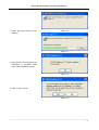
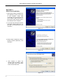
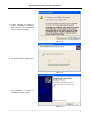
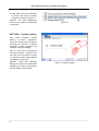
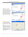
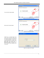
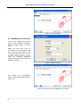
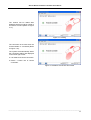
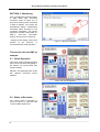
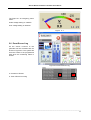
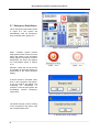
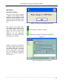
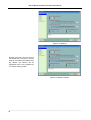
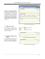
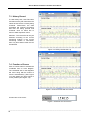
KCU-01 Monitor
Software Installation User Manual
For Windows XP and Windows 7
Headquarters : No.3, Lane 201, Chien Fu ST., Chyan Jenn Dist., Kaohsiung, TAIWAN
Tel : + 886-7-8121771
Fax : + 886-7-8121775
URL : http://www.kutai.com.tw
KCU-01 Monitor Software Installation User Manual
TABLE OF CONTENTS
Section
Section 1
Section 2
Section 3
Section 4
Section 5
Section 6
Section 7
Page
Application Installation......................................................................................................... 3
USB Driver Installation ........................................................................................................ 6
System Setting .................................................................................................................... 8
Connection ........................................................................................................................ 10
Monitoring.......................................................................................................................... 14
Parameter Setting ............................................................................................................. 19
Figure Recording ............................................................................................................... 21
______________________________________________________________________________________
2
KCU-01 Monitor Software Installation User Manual
SECTION 1 :
Application Installation
1. Insert the installation Disk into CD
ROM drive.
2. Double click on file setup.exe to
begin installation.
Figure 1-1
3. Select the primary installation
directory and press Next.
Figure 1-2
4. The Installation Wizard will display
the summary of installation
content, and then press Next.
Figure 1-3
______________________________________________________________________________________
3
KCU-01 Monitor Software Installation User Manual
5. Software installing
Figure 1-4
6. Installation completed. Press Next
Figure 1-5
______________________________________________________________________________________
4
KCU-01 Monitor Software Installation User Manual
7. Install Run-Time Engine Driver
software.
Figure 1-6
Figure 1-7
8. When the Run-Time Engine Driver
installation is completed, press
OK to finish installation process.
Figure 1-8
9. Click on Yes to restart.
Figure 1-9
______________________________________________________________________________________
5
KCU-01 Monitor Software Installation User Manual
SECTION 2 :
USB Driver Installation
1. After placing KCU-01 Module into
the expansion socket in the back
of the controller; using USB
connecting wire, connect the one
end of Mini-A USB connector to
the KCU-01 and the other end to
the USB port of the computer.
2. The Found New Hardware Wizard
will appear, please select “No, not
this time” as showed below and
click Next.
Figure 2-1
3. Please select “Install from a list or
specific location (Advance)”, and
click Next.
Figure 2-2
4. Click Browse to select the
directory (refer to Chapter 1 step
3) find folder “driver” and select
kcu01.inf and click Next.
Figure 2-3
______________________________________________________________________________________
6
KCU-01 Monitor Software Installation User Manual
5. A Note message of inability to
confirm compatibility will appear.
Please ignore such message and
click on “Continue Anyway”.
Figure 2-4
6. The system will then install Drivers.
Figure 2-5
7. The completion of Driver
complete then press “Finish”.
is
Figure 2-6
______________________________________________________________________________________
7
KCU-01 Monitor Software Installation User Manual
8. Click opens the Device Manager
to check if the Driver is properly
installed, as shown in Figure 2-7.
Attention : the COM configuration
showed is the COM Port required for
connections.
Figure 2-7
SECTION 3 : System Setting
This section illustrates System
Setting of KCU-01 application.
Users can modify Event Log Record
and Data Log Record, or relevant
parameter of data acquisition and
change the language setting.
Click to open KCU-01 Monitor.exe
and select “Setting
Options” from
the main menu as shown in Figure
3-1. Open the system setting window
as displayed in Figure 3-2.
Attention : Other than Language
Setting, the system must restart after
modifying the system setting before
the new setting will take effect.
Figure 3-1 Options Setting
______________________________________________________________________________________
8
KCU-01 Monitor Software Installation User Manual
Each System setting is illustrated
below :
● Event Log Record Path
It programs the path for event log
record. The system will automatically
record the event when the controller
sends out a Note signal and such
record will then be saved as file.
Attention:Event Log Record is not
available on ATS-PLC.
● Data Log Record Path
The system will acquire data and
save as file with each period interval
when monitoring is turned on. This
setting can modify the content of
Figure record storage file.
Models available with Data Log
Record:AMF-10, GCU-100, GCU-3000
● Data Acquisition Interval
It is programmed to acquire data
within couple of second which will
save acquired data into files. The
system will automatically create a
new file for storage after 00:00
o’clock which is able to record up to
23:59 o’clock each day.
Figure 3-2 Program Setting
Attention : More frequent the
recording interval is, larger the size
of stored file becomes.
● Data Storage Interval
● Language
At the end of each connection, the
system will automatically save the
acquired data into file. The amount of
data accumulated before saving
within the acquisition interval can be
adjusted here. Saving within each
interval will ensure the data storage.
It will automatically change the
displayed language. Not only will
modifying language setting change
the display language, it will also
affect the language of events log
record.
Attention : The efficiency of the
system will be affected if the data
storage is set frequent.
______________________________________________________________________________________
9
KCU-01 Monitor Software Installation User Manual
SECTION 4 : Connection
Connect one end of Mini-A USB to
KCU-01 Module and the other end to
the computer. Make sure the power
of the controller is turned on before
opening the KCU-01 Monitor exe.
Figure 4-1 USB Port
KCU-01 has two kinds of connection
mode:USB Port and USB Modem
Connection (Refer to Figure 4-1 and
4-2).
Figure 4-2 USB Modem
4.1 USB Port Connection
Click on Link and main menu and
select USB to open USB Connection
Setting Window (Refer to Figure
4-3).
Select COM Port connecting to the
KCU-01 Module and click on
Connect Button. If the connection is
successful, it will return to Main
Menu and display the connection
status (Refer to Figure 4-4) ; if the
connection failed, it will also returned
to Main Menu but with no connection
status (Refer to Figure 4-5).
Figure 4-3 USB Connection Window
______________________________________________________________________________________
10
KCU-01 Monitor Software Installation User Manual
The connection status display.
Figure 4-4 Successful Connection
Disconnection status display.
Figure 4-5 Connection Failure
COM Port is occupied when user
enter USB Connection Setting and
the COM Port appear to be gray and
not selectable (Refer to Figure 4-6).
Please disconnect by returning to the
Main Menu and select Link
Disconnect (Refer to Figure 4-7),
then re-select correct COM Port for
connection.
Figure 4-6 COM Port Occupied
______________________________________________________________________________________
11
KCU-01 Monitor Software Installation User Manual
Figure 4-7 Disconnecting
4.2 USB Modem Connection
Click on Link
Modem of the main
menu to open Modem Connection
Setting Window. (Refer to Figure
4-8).
Select the COM Port which is
connected to the USB Modem, and
then choose the Baud Rate for the
connection (Must be same as the
controller internal setting). At last,
enter the receiver’s telephone
number and press connect button for
Modem connection.
Figure 4-8 Modem Setting
The system will automatically
initialize connected Modem (Refer to
Figure 4-9 ).
Figure 4-9 Ensure whether the Modem is connected
______________________________________________________________________________________
12
KCU-01 Monitor Software Installation User Manual
The number will be dialed after
initializing which may takes couple of
seconds to connect (Refer to Figure
4-11).
Figure 4-11 Dialing
The connection is success when the
remote Modem is connected (Refer
to Figure 4-12).
The system will automatically detect
the connection setting and displayed
on the lower right corner.
● Link:Method of current connection.
● Device : Control unit of current
connection.
Figure 4-12 Modem Connection Successful
______________________________________________________________________________________
13
KCU-01 Monitor Software Installation User Manual
SECTION 5 : Monitoring
Click on the Remote Controller Button
in Main Menu after successful
connection (refer to Figure 5-1) to
open the monitoring frame connected
to KCU-01 Module. The system will
automatically display corresponding
monitoring frame according to the
connection information. The current
supportive modules include AMF-10,
AMF-11,
GCU-100,
GCU-3000,
ATS-22, ATS-33, ATS-34, ATS-PLC.
* Majority of the display content and
function of the ATS-PLC, is
synchronized with actual operation
Figure 5-1 Remote Controller
This section will use AMF as
example.
5.1 Virtual Operation
This is the virtual controller operation
panel. All the functions and lighting of
the buttons are synchronized with
actual controller.
Attention:The displayed frame varies
with different connected control
modules.
Figure 5-2 Virtual Operation
5.2 States of Generator
The current state of generator is
shown in Figure 5-3. There are total
of seven states listed below.
Figure 5-3 State of generator
______________________________________________________________________________________
14
KCU-01 Monitor Software Installation User Manual
Running
Engine shut-down.
Engine Coiling down.
Stop
Pre-Heat
Cranking
Idle
5.3 Other Information
Shown in Figure 5-4
Attention:The displayed frame varies
with different connected control
modules.
● Maintain (HH:mm):Maintain service
countdown.
● Run Hr.(H:m):Hours of operating.
● Battery:DC Voltage.
Figure 5-4 Other Information
______________________________________________________________________________________
15
KCU-01 Monitor Software Installation User Manual
5.4 Connection Status
As shown in Figure 5-5 displays the
current controller connection status.
● Link:There are two connection
methods to KCU-01 module, USB
Port Connection and Modem
Connection. It will display the
connection method here.
● Device : The control module of
current connection.
Figure 5-5 Connection Status
Connecting
Connection Status
Disconnecting
5.5 Meter Area
This area display the configuration
monitored by the controller shown in
Figure 5-6. The scale will be varied
as the corresponding setting of
different controller is different.
Attention:The displayed frame varies
with different connected control
modules.
Figure 5-6 Scale Parameter
______________________________________________________________________________________
16
KCU-01 Monitor Software Installation User Manual
The Figure 5-7 is emergency power
meter.
Under voltage setting on 180VAC.
Over voltage setting on 250VAC
Figure
5-7
5.6 Event Record Log
All the events occurred to the
generator will be recorded here as
shown in Figure 5-8. The system will
save the events to the programmed
path when the monitoring frame is
closed.
Figure 5-8 Events Record Log
a. Contents of Events.
a
b
b. Time of Event Occurring
______________________________________________________________________________________
17
KCU-01 Monitor Software Installation User Manual
5.7 Emergency Stop Button
This is emergency stop button shown
in Figure 5-9. The system will
automatically send out emergency
stop command when clicked on it.
Figure 5-9 Emergency Stop Button
When controller system internal
setting allow remote access, then the
button will appear to be accessible
status (Figure 5-10); When access is
deactivated, the button will appear
as un-accessible shows in (Figure
5-11).
Figure
5-10
Figure
5-11
Attention:When the remote access
is cancelled, all executing button are
deactivated on the virtual operation
display.
If remote access is activated, when
click on the emergency stop button,
a pop up window will appear and
requesting for confirmation of
execution. Click OK and system will
immediately execute emergency
engine stop.
Ensure whether to activate emergency stop
The pointer will pop up when clicking
on the emergency stop button with
the controller switch OFF.
It will show OFF mode already
______________________________________________________________________________________
18
KCU-01 Monitor Software Installation User Manual
SECTION 6 :
Parameter Setting
From main screen, select “Controller
Setting” to open parameter setting.
Controller must be switched to OFF
status prior to programming, otherwise
system will not be permitted to enter
parameter setting screen (See Figure
6-1).
Figure 6-1 Can only enter setting at OFF Mode
After opening up the setting page,
and changed the parameter(s), if the
new setting differs from previous
setting, the green markers (See
Figure 6-2) on the left of the
parameter will be highlighted,
indicating has changed the setting
and waiting to be updated.
:Default setting or setting not changed.
:Parameter(s) changed and awaiting to be updated.
Figure 6-2
Example:In Figure 6-3, 2 parameters
have been changed, after clicking on
the Update button the system will
execute remote update. The update
process usually take a few seconds
only, some updates are immediately
effective and displayed (Reference
from Figure 5-7)
Figure 6-3 Modified Entry will be marked
______________________________________________________________________________________
19
KCU-01 Monitor Software Installation User Manual
Figure 6-4 Updating
Default, in anytime, user can click on
the Default key to resume to factory
settings. Any setting that differs from
the default, the markers will be
highlighted. Click on the Update key
to continue setting update.
Figure 6-5 Update Complete
______________________________________________________________________________________
20
KCU-01 Monitor Software Installation User Manual
Section 7 : Figure Recording
The system starts recording once the
monitoring window is opened. Data
will be graphed into curve diagram
according to the acquisition interval
set by the user. Vertical coordinate of
each diagram will adjust automatically.
Select “Controller
Record” from the
main menu to open the diagram (Refer
to Figure 7-1).
Figure 7-1 Graph Record Log
7.1 Show Curve Lines
The selection box enable user to
choose whether to display curves
which enables user to better observe
certain curve graphic.
: Show Curve Lines
: Hide Curve Lines
7.2 Drop-Down Menu Scale
Range
Figure 7-2 Within 10 minutes Range
It can adjust the length of data to be
showed at once with scale range of 1
minute, 10 minute, 30 minutes, 1
hour, 5 hours, 10 hours and one day.
Figure 7-3 Within 1 minute Range
______________________________________________________________________________________
21
KCU-01 Monitor Software Installation User Manual
7.3 History Record
To view history files, click File button
and select history file of which the file
names shows the file currently being
reviewed. Furthermore, the data
acquisition will continue processing
wile files are being opened and
reviewed. Click on Close File to
return to data acquisition menu.
Attention:The record file can only be
selected according to the current
monitoring module. If the current
monitoring module is GCU-3000,
then only GCU-3000 record file can
be selected.
Figure 7-4 History File Record Log
7.4 Function of Cursor
Click on Cursor button to activate the
coordinate axis on each diagram.
The coordinate axis on the diagrams
will move along with the motion of
mouse simultaneously (See Figure
7-5) and display the time period of
cursor position (See Figure 7-6).
Figure 7-5 Cursor moves with the mouse
Current time of the cursor
Figure 7-6 Shower the current time
______________________________________________________________________________________
22