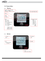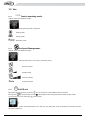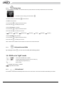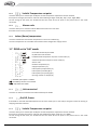
1
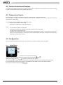
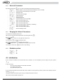
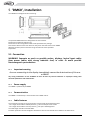
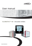
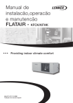
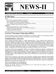
User manual DC 60 DM 60 DC 60 & DM 60 displays DC60-DM60_ROOFTOP-IOM-1310-E lennoxemeia.com Summaries 1 Display ‘DC60’ 1.1 1.2 1.3 1.4 1.5 1.6 1.7 1.8 1.9 Introduction ................................................................................................................................. 2 Temperature measurement ........................................................................................................ 2 Quick Action ................................................................................................................................. 3 Presentation ................................................................................................................................ 6 Use ............................................................................................................................................... 7 DC60 set in ‘Light’ mode .............................................................................................................. 8 DC60 set in ‘Full’ mode ................................................................................................................ 9 Setting Value ............................................................................................................................ 11 Activation level 2 ....................................................................................................................... 11 2 Display ‘DM60’ 3 Alarm List by Code ..................................................................................................... 23 4 DC60, Installation 5 6 2.1 Quick Action ............................................................................................................................... 12 2.2 Functionality of the DM60 ......................................................................................................... 15 2.3 Organizational screens............................................................................................................... 21 4.1 4.2 4.3 4.4 4.5 Connection ................................................................................................................................. 26 Ferrites Protection of Displays ................................................................................................... 28 Temperature Sensor .................................................................................................................. 28 Configuration ............................................................................................................................. 28 Initialization ............................................................................................................................... 29 ‘DM60’, Installation 5.1 5.2 5.3 5.4 Connection ................................................................................................................................. 30 Connection on the splitter DT50 ................................................................................................ 30 Ferrites Protection of Displays ................................................................................................... 31 Configuration ............................................................................................................................. 32 DC60-DM60 Communication Master/Slaves 6.1 Connection ................................................................................................................................. 33 DC60-DM60-ROOFTOP-IOM-1310-E -1- 1 Display ‘DC60’ 1.1 Introduction The display ‘DC60’ is customized for the user. It allows an overview of the operation of the Unit and allows access to some parameters. Depending on the setting in the Climatic, two display configurations are possible: • Mode ‘Light’ • Mode ‘Full’ The 'DC60' is designed to be remotely connected of the Unit. The 'DC60' is equipped with a temperature sensor. The temperature sensor allows the acquisition of room temperature to control. 1.2 Temperature measurement All Lennox Unit comes with a temperature sensor; it must be placed in the conditioned area. But if the 'DC60' is placed in the area conditioned by the Unit, it is possible, in this case, to use the temperature measurement of the 'DC60'. DC60-DM60-ROOFTOP-IOM-1310-E -2- 1.3 Quick Action 1.3.1 How to See the Operation of the Unit 4 ? Only if several units are connected to the DC60. Turn the knob to have the text ‘Unit’. Press the knob to switch in 'Set' mode. Turn the knob to select number 4. Press the knob to confirm your choice 1.3.2 How to Start all Units connected at this DC60 ? Press the button a few seconds. The units can not be powered On/Off by the DC60 if the service display DS60 is connected. DC60-DM60-ROOFTOP-IOM-1310-E -3- 1.3.3 How to Start Unit 4 ? Only if several units are connected to the DC60. Select the Unit 4 (see: How to See the Operation of the Unit 4 ?) Turn the knob to have the text ‘I-O’. Press the knob to switch in 'Set' mode. Turn the knob to select number 1 (1 for ‘On’, 0 for ‘Off’). Press the knob to confirm your choice The units can not be powered On/Off by the DC60 if the service display DS60 is connected. 1.3.4 How to See the Value of the Current Setpoint Temperature ? Turn the knob to have the text ‘Set’. The value displayed is the temperature setpoint. DC60-DM60-ROOFTOP-IOM-1310-E -4- 1.3.5 How to Modify the Value of the Current Setpoint Temperature ? Turn the knob to have the text ‘Set’. Press the knob to switch in 'Set' mode. Turn the knob to change the value. Press the knob to confirm your choice DC60-DM60-ROOFTOP-IOM-1310-E -5- 1.4 Presentation 1.4.1 Showing 1.4.2 Buttons DC60-DM60-ROOFTOP-IOM-1310-E -6- 1.5 Use Control operating mode. 1.5.1 Only for Flatair and Aqualean ranges. Press until the desired operating mode is displayed. Heating mode Cooling mode Automatic mode 1.5.2 Fan Speed Management. Only for Flatair and Aqualean ranges. Press to select the desired speed (min, med, max) or automatic (Auto). Minimum speed Median speed Maximum speed Automatic Speed 1.5.3 On/Off unit By supporting a few seconds, the button If the symbol completed by the time To restart the unit, press the button you can activate or not (On/Off) the Unit connected. is displayed, the Unit is stopped and the 'DC60' in sleep mode. a few seconds If the DC60 is used with the Master/Slaves bus in this case, the 'Off' phase, stops all Rooftop connected on the Bus, 'On' phase restarts all. DC60-DM60-ROOFTOP-IOM-1310-E -7- Setting time 1.5.4 At initialization of the 'DC60', the Climatic™60 are synchronized time and day of week with the clock 'DC60'. To view the clock, briefly, press the button To set the clock press the button a few seconds The hour value, flashes. Turn the knob to adjust the desired value. Press the knob to select your choice. Then the minute value, flashes. Turn the knob to adjust the desired value. Press the knob to select your choice. Monday | | Tuesday | Wednesday | Thursday | Friday | Saturday | Sunday | Then the weekday value, flashes. Turn the knob to adjust the desired value. Press the knob to select your choice. After a few seconds 'DC60' communicates the new time to the Climatic™60. Information available 1.5.5 By rotating the knob you can view or modify the following values: 1.6 DC60 set in ‘Light’ mode : : : *: Unit Index selected by the ‘DC60’ : Volatile temperature set point current mode (°C) Indoor (Room) temperature (°C) Alarms code * : Available if the option is enabled. : Adjustable with ‘DC60. 1.6.1 Unit selected If the DC60 is used with the Master/Slaves bus this item can select or know the Unit Index selected by the 'DC60'. DC60-DM60-ROOFTOP-IOM-1310-E -8- 1.6.2 Volatile Temperature set point This item allows you to view and/or modify the control temperature required for the Unit selected. If this point is changed, this value is used until the scheduling changes mode (Day, Day I, Day II, Night, BMS). At each change of the mode, the Climatic™60 sets the value of this set point on the preset value in the mode concerned. 1.6.3 Alarms code This item allows you to view the code of different active alarms on the Unit. If the Unit isn't in alarm, this item is to 0. 1.6.4 Indoor (Room) temperature This item indicates the measured air temperature in the room conditioning. The room temperature isn't available if the Climatic™60 is configured to supply control. 1.7 DC60 set in ‘Full’ mode - : *: - : : : Unit Index selected by the ‘DC60’ On/Off of the Unit selected. Predetermined temperature set point current mode (°C) Volatile temperature set point current mode (°C) Alarms code - *: Outdoor temperature (°C) - *: : *: Supply temperature (°C) Indoor (Room) temperature (°C) Indoor (Room) humidity (%hr) - *: *: Indoor (Room) Air quality (ppm) Opening of fresh air damper (%) * : Available if the option is enabled. : Available if the level 2 is activated. : Adjustable with ‘DC60. 1.7.1 Unit connected This item can select or know the Unit Index selected by the 'DC60'. 1.7.2 On/Off, Power If the DC60 is used with the Master/Slaves bus this item allows you to view and/or change the status of starting or stopping of the Unit selected. 1.7.3 Volatile Temperature set point This item allows you to view and/or modify the control temperature required for the Unit selected. If this point is changed, this value is used until the scheduling changes mode (A, B, C, D, BMS). At each change of the mode, the Climatic™60 sets the value of this set point on the preset value in the mode concerned. DC60-DM60-ROOFTOP-IOM-1310-E -9- 1.7.4 Predetermined Temperature set point If level 2 is active, this item allows you to view and/or change the preset temperature control for the active mode. 1.7.5 Alarms code This item allows you to view the code of different active alarms on the Unit. If the Unit isn't in alarm, this item is to 0. By this item it's possible to reset the alarm activated. To do this set the value of the item to the value 0. 1.7.6 Outdoor temperature This item indicates the measure temperature of the air outside. The outside temperature isn't available for the WSHP range. 1.7.7 Supply temperature This item indicates the measure of outlet air temperature of the Unit. 1.7.8 Indoor (Room) temperature This item indicates the measured air temperature in the room conditioning. The room temperature isn't available if the Climatic™60 is configured to supply control. 1.7.9 Indoor (Room) relative humidity This item shows the measured relative humidity of the air in the room conditioning. The room humidity isn't available if the option of humidity management isn't set. 1.7.10 Measurement of CO² This item indicates the measured rate of CO² in conditioning room, in ppm. The measurement of CO² isn't available if the option isn't set. 1.7.11 Opening of fresh air damper This item indicates the measured value of the opening rate of the fresh air damper, in%, (mixture of outside air and return air) This value is only available if the Unit is equipped with this option. DC60-DM60-ROOFTOP-IOM-1310-E - 10 - 1.8 Setting Value If the value of the selected item is modified To activate the modified value . Press the knob . The symbol appears on the right side of the value. Turn the knob to adjust the desired value. Press again on the knob to confirm your choice. The symbol is no longer displayed on the right side of the value. The rotation of the knob is for select a new item. 1.9 Activation level 2 (2 buttons on the right simultaneously) Simultaneously press the keys After some seconds the text and . appears and the value '000' flashes. Turn the knob to change the value to select the number 066. Then validate the code by pressing the knob. If the code is wrong access the setup menu is not possible and the 'DC60' returns to the previous display. If the code is correct the level 2 is actif, and symbol is displayed to the right of the value. The level 2 is turned off automatically every hour. DC60-DM60-ROOFTOP-IOM-1310-E - 11 - 2 Display ‘DM60’ The display 'DM60' is customized for the user. It allows an overview of the operation of the Unit and allows access to some parameters. The 'DM60' is designed to be remotely connected of the Unit. The 'DM60' can be connected to several Lennox Units, Between 1 and 8 units 2.1 Quick Action 2.1.1 How to See the Operation of the Unit 4 ? Press, several times, the button ‘Esc’ to display the page 'Unit'. Press, several times, the button ‘Down’ to select number 4 Press ‘Enter’ to confirm your choice DC60-DM60-ROOFTOP-IOM-1310-E Display for a unit to ‘On’ Display for a unit to ‘Off’ - 12 - 2.1.2 How to Start Unit ? Press ‘Prg’ to activate the setup menu If necessary, press several times ‘Up’ or ‘Down’ to blacken the icon Press ‘Enter’ to confirm your choice Press ‘Up’ or ‘Down’ to change the state ‘Off’ to ‘On’ Press ‘Enter’ to confirm your choice Press ‘Esc’ to return to the main screen The units can not be powered On/Off by the DM60 if the service display DS60 is connected. DC60-DM60-ROOFTOP-IOM-1310-E - 13 - 2.1.3 How to See the Value of the Current Setpoint Temperature ? Press ‘Prg’ to activate the setup menu If necessary, press several times ‘Up’ or ‘Down’ to blacken the icon The value displayed is the temperature setpoint. Press ‘Esc’ to return to the main screen 2.1.4 How to Modify the Value of the Current Setpoint Temperature ? Press ‘Prg’ to activate the setup menu If necessary, press several times ‘Up’ or ‘Down’ to blacken the icon Press ‘Enter’ to confirm your choice Press ‘Up’ or ‘Down’ to change the value Press ‘Enter’ to confirm your choice Press ‘Esc’ to return to the main screen DC60-DM60-ROOFTOP-IOM-1310-E - 14 - 2.2 Functionality of the DM60 Selection of Unit 2.2.1 A DM60 can be connected to 8 units on the pLan bus. Screens DM60 connected, alternatively, to one of BM60. The next screen allows selection of the unit to display: Each of the 8 Unit is represented by a number. The Unit selected is indicated by its number which is framed. Each time you press the button 'Down Arrow' connects the display on the next Unit. Button 'Enter': Go to main screen. Button 'Down Arrow': Select the next Unit. Unit ‘Off’ 2.2.2 If the Unit is stopped 'Off', this screen is activated. Button 'Alarm': Go to Alarm list. Button 'Prg': Go to Setup menus of the unit. Button 'Esc': Return to the choice of Unit selected. Unit Operation 2.2.3 2.2.3.1 Main Top left : Control in heating mode or control in cooling mode Big, numerical value: Measured value of the air temperature in the conditioned space. Top right: State of the ventilation Bottom right: Mode state based on the schedule, hour, minute, of Climatic™ : Mode Night Mode Day DC60-DM60-ROOFTOP-IOM-1310-E - 15 - Mode Day I Mode Day II Bottom left: If the unit is in alarm, this symbol is displayed. Button 'Alarm': Go to Alarm list. Button 'Prg': Go to Setup menus of the unit. Button 'Esc': Return to the choice of Unit selected. Button 'Up Arrow': Go to another display of the Unit operation. Button 'Down Arrow': Go to another display of the Unit operation. 2.2.3.2 Value To the left of the house: Visualization of the value of outdoor humidity (if enabled). Visualization of the value of outdoor temperature. In the house: Visualization of the value of indoor humidity (if enabled). Visualization of the value of the indoor temperature. Visualization of the value of the rate of indoor air quality (if enabled). 2.2.3.3 Set-points Visualization of the set point of heating mode. Visualization of the set point of cooling mode. 2.2.3.4 Operation Visualization of the opening percentage of fresh air damper. Visualization of the percentage of compressors engaged. Visualization of the percentage of heaters engaged. Button 'Alarm': Go to Alarm list. Button 'Prg': Go to Setup menus of the unit. Button 'Esc': Return to main screen. Button 'Up Arrow': Go to previous display of the Unit operation. Button 'Down Arrow': Go to next display of the Unit operation. DC60-DM60-ROOFTOP-IOM-1310-E - 16 - 2.2.4 Alarm list History used to store the last 99 alarms occurred on the unit. Each alarm is stored on the date and time the fault occurred. An active alarm is signified by the symbol 'Bell'. An alarm not active is signified by the symbol '.'. Each alarm is signified by a 3 digit code To have the text of fault code, position the cursor on the desired line, by using the 'Up Arrow' or 'Down Arrow' and then confirm by pressing 'Enter' Button 'Esc': Return to main screen. Button 'Up Arrow': Positions you in the list. Button 'Enter': Go to text of failure code. Button 'Down Arrow': Positions you in the list. 2.2.5 Setup menus Button 'Alarm': Go to Alarm list. Button 'Esc': Return to main screen. Button 'Up Arrow': Selects the previous function. Button 'Enter': Go to the screen of the selected function. Button 'Down Arrow': Selects the next function. 2.2.6 Setting; Customer Temperature View and/or modify the offset, or set point, of the temperature control desired for the Unit selected. If the set-point is changed, this value is maintained as long as the scheduling of Unit doesn't change modes (Night, Day, Day I, Day II, BMS). At each change of the mode the Climatic™60 sets the value of this set-point on the preset value in the mode concerned. Button 'Alarm': Go to Alarm list. Button 'Esc': Return to Setup menus of the unit. DC60-DM60-ROOFTOP-IOM-1310-E - 17 - Button 'Up Arrow': Increases the set-point value. Button 'Enter': Valid the changes then return to Setup menus of the unit. Button 'Down Arrow': Decreases the set-point value. 2.2.7 Setting; On/Off Unit View/edit, status of Off/On of the unit. Button 'Alarm': Go to Alarm list. Button 'Esc': Return to Setup menus of the unit. Button 'Up Arrow': Reverses the state. Button 'Enter': Valid the changes then return to Setup menus of the unit. Button 'Down Arrow': Reverses the state. The units can not be powered On/Off by the DM60 if the service display DS60 is connected. 2.2.8 Setting; Clock of Climatic™ View/edit, hour, minute, day of month, month and year of the clock Climatic™. Button 'Alarm': Go to Alarm list. Button 'Esc': Return to Setup menus of the unit. Button 'Up Arrow': Increases the selected value. Button 'Enter': Valid the changes and puts you to the next field. Button 'Down Arrow': Decreases the selected value. 2.2.9 Access to the Setup Menus Plus DC60-DM60-ROOFTOP-IOM-1310-E - 18 - 2.2.10 Setup menus Plus Access to the setup menus is protected by a password. The password must be entered digit by digit. If the password is correct, the lock opens, and the selection of the choice of function is active. Button 'Alarm': Go to Alarm list. Button 'Esc': Return to Setup menus of the unit. Button 'Up Arrow': Increases the value of the digit password or Selects the previous function. Button 'Enter': Puts you on the next digit password, or Go to the screen of the selected function. Button 'Down Arrow': Decreases the value of the digit password or Selects the next function. 2.2.11 Setting; Temperature View/edit, the set-point heating mode of the schedule mode selected. View/edit, the set-point cooling mode of the schedule mode selected. Button 'Alarm': Go to Alarm list. Button 'Esc': Return to Setup menus Plus of the unit. Button 'Up Arrow': Change the schedule mode or Increases the set-point value. Button 'Enter': Valid the changes and puts you to the next field. Button 'Down Arrow': Change the schedule mode or Decreases the set-point value. 2.2.12 Setting; Report Minimum Fresh-Air. View/edit, the set-point minimum fresh-air of the schedule mode selected. Button 'Alarm': Go to Alarm list. Button 'Esc': Return to Setup menus Plus of the unit. DC60-DM60-ROOFTOP-IOM-1310-E - 19 - Button 'Up Arrow': Change the schedule mode or Increases the set-point value. Button 'Enter': Valid the changes and puts you to the next field. Button 'Down Arrow': Change the schedule mode or Decreases the set-point value. 2.2.13 Setting; Reset Alarms View/edit, reset of alarm and safety. Button 'Alarm': Go to Alarm list. Button 'Esc': Return to Setup menus Plus of the unit. Button 'Up Arrow': Reverses the state. Button 'Enter': Reset alarms, if the word 'Reset' is selected, then return to Setup menus Plus. Button 'Down Arrow': Reverses the state. 2.2.14 Setting; Schedule of Climatic™ View/edit, hour and minutes of beginning of each zone. View/edit, the operating mode of the zone. The schedule is different each weekday. You must set a schedule for Monday, Tuesday, ..., and Sunday. Button 'Alarm': Go to Alarm list. Button 'Esc': Return to Setup menus Plus of the unit. Button 'Up Arrow': Change the schedule mode or Increases the selected value. Button 'Enter': Valid the changes and puts you to the next field. Button 'Down Arrow': Change the schedule mode or Decreases the selected value. DC60-DM60-ROOFTOP-IOM-1310-E - 20 - 2.3 Organizational screens 2.3.1 Selection of Unit 2.3.2 Unit Operation 2.3.3 Alarm list DC60-DM60-ROOFTOP-IOM-1310-E - 21 - 2.3.4 Setup menus DC60-DM60-ROOFTOP-IOM-1310-E - 22 - 3 Alarm List by Code Code 001 Alarm Blower, Flow Switch Cut Off 002 Water Condenser, Flow Switch Cut Off 003 Water Condenser, Flow Delta-T 004 Blower, Filters, Dirty 005 Blower, Filters, Missing 009 Unit Power Supply 011 Electrical Heaters, Overheating 012 Fresh Air, Electrical Heater, Overheating 013 Hot Water, Risk Of Frosting 014 Gas Burner 1 015 Gas Burner 2 016 Gas Burner, Overheating 021 Supply Temperature, Too High 022 Supply Temperature, Too Low 023 Room Temperature, Too High 024 Room Temperature, Too Low 025 Water Condenser Temperature, Too Low 026 Water Condenser Temperature, Too High 027 Water Condenser, Pump 029 Air Quality, Too High 031 Humidifier, Failure 032 Room Humidity, Too Low 033 Room Humidity, Too High 041 Pump 051 Recovery, Motor 052 Recovery, Wheel 054 Recovery, Filters, Dirty 056 Recovery, Air Flow, Sensor 059 Recovery, Outlet Temperature, Probe 070 Real Time Clock 071 BE.1, Communication Bus 072 BE.2, Communication Bus 073 Blower, Inverter, Communication Bus 074 Exhaust, Inverter, Communication Bus 075 Circuit 1, Condenser Fan, Inverter, Communication Bus 076 Circuit 2, Condenser Fan, Inverter, Communication Bus 080 Air Flow, Sensor 081 Room Temperature, Probe 082 Room Humidity, Sensor 083 Outside Temperature, Probe 084 Outside Humidity, Sensor DC60-DM60-ROOFTOP-IOM-1310-E - 23 - Code 085 Alarm Supply Temperature, Probe 086 Water Condenser, Inlet, Probe 087 Water Condenser, Outlet, Probe 088 Return Temperature, Probe 089 Air Quality, Sensor 090 Blower Pressure, Sensor 091 Blower, Fan 092 Blower, Inverter 093 Exhaust, Fan 094 Exhaust, Inverter 099 Fire / Smoke, Detected 101 EVD, Communication Bus 102 Circuit 1, Condenser Fan 103 Circuit 1, Condenser Fan, Inverter 110 Circuit 1, Leak Refrigerant, Detected 114 Circuit 1, Compressor, Electrical 115 Circuit 1, High Pressure Cut Off 116 Circuit 1, Reversing Valve, Blocked 117 Circuit 1, Low Pressure Cut Off 118 Circuit 1, Risk Of Frosting 119 Circuit 1, Low Condensing Temperature 121 Circuit 1, Low Superheat 122 Circuit 1, High Superheat 123 Circuit 1, Low Subcooling 124 Circuit 1, High Subcooling 127 Circuit 1, MOP, Maximum Operating Pressure 128 Circuit 1, LOP, Low Operating Pressure 129 Circuit 1, High Condensing Temperature 130 Circuit 1, Discharge Temperature, Compressor 1, Overheating 132 Circuit 1, Expansion Valve, Motor 141 Circuit 1, High Pressure, Sensor 142 Circuit 1, Low Pressure, Sensor 143 Circuit 1, Liquid Temperature, Probe 144 Circuit 1, Suction Temperature, Probe 145 Circuit 1, Discharge Temperature, Compressor 1, Faulty Probe 202 Circuit 2, Condenser Fan 203 Circuit 2, Condenser Fan, Inverter 210 Circuit 2, Leak Refrigerant, Detected 214 Circuit 2, Compressor, Electrical 215 Circuit 2, High Pressure Cut Off 216 Circuit 2, Reversing Valve, Blocked 217 Circuit 2, Low Pressure Cut Off 218 Circuit 2, Risk Of Frosting DC60-DM60-ROOFTOP-IOM-1310-E - 24 - Code 219 Alarm Circuit 2, Low Condensing Temperature 221 Circuit 2, Low Superheat 222 Circuit 2, High Superheat 223 Circuit 2, Low Subcooling 224 Circuit 2, High Subcooling 227 Circuit 2, MOP, Maximum Operating Pressure 228 Circuit 2, LOP, Low Operating Pressure 229 Circuit 2, High Condensing Temperature 232 Circuit 2, Expansion Valve, Motor 241 Circuit 2, High Pressure, Sensor 242 Circuit 2, Low Pressure, Sensor 243 Circuit 2, Liquid Temperature, Probe 244 Circuit 2, Suction Temperature, Probe 310 Circuit 3, Leak Refrigerant, Detected 314 Circuit 3, Compressor, Electrical Failure 315 Circuit 3, High Pressure Cut Off 316 Circuit 3, Reversing Valve, Blocked 317 Circuit 3, Low Pressure Cut Off 319 Circuit 3, Low Condensing Temperature 321 Circuit 3, Low Superheat 322 Circuit 3, High Superheat 323 Circuit 3, Low Subcooling 324 Circuit 3, High Subcooling 327 Circuit 3, MOP, Maximum Operating Pressure 328 Circuit 3, LOP Low Operating Pressure 329 Circuit 3, High Condensing Temperature 341 Circuit 3, High Pressure, Faulty Sensor 342 Circuit 3, Low Pressure, Faulty Sensor 343 Circuit 3, Liquid Temperature, Faulty Probe 344 Circuit 3, Suction Temperature, Faulty Probe DC60-DM60-ROOFTOP-IOM-1310-E - 25 - 4 DC60, Installation The 'DC60' has been designed for flush mount assembly, on distribution boxes compliant with the standards in force. 4.1 Connection WARNING: Separate as much as possible probes, displays, logical input cables from power cables with strong inductive load, in order to avoid possible electromagnetic perturbations. 4.1.1 Important warning An error connecting to the display immediately causes the deterioration of this one or BM60. Any wiring modification on the CLIMATIC 60 must be done by Lennox technician or employees having valid electrical qualification and authorization. DC60-DM60-ROOFTOP-IOM-1310-E - 26 - 4.1.2 Power supply The power of the 'DC60' can be 24Vac (+10…-15%) 50/60Hz or 24Vdc (22…35Vdc), maximum current of 2VA. Lennox recommends a 24Vac supply (provided by Unit) for installation of the display less within 30 meters of Unit. For connection of the display of over 30 meters, a power supply, close to the display, 24Vac must be provided by the installer. For an external connection to the Unit (24V) using a transformer class 2 under 0.1A For any modification of wiring on the 24V supply or on 4-20mA sensor, check the polarity prior to apply the power. Wrong polarity may cause serious damage and destroy the Plan network. Lennox will not accept liability for damage caused by wrong power connection or any wiring modification done by people without valid training and qualifications. 4.1.3 Communication The 'DC60' is controlled by a communication bus: RS485 2 wires. 4.1.4 Cable Features The connection of power and communication must be made by the following cable: - LiYCY-P (0.34 mm ²), 2 pairs with general shield. The cable length, with power, should not exceed 30m. The cable length without power (24V external) must not exceed 150m. For a better electromagnetic protection, Lennox recommends the use of LiYCY-P cable For extended networks fit a 120 Ohm resistor (R2) between RX/TX+ and RX/TX- on the last device, to avoid possible communication problems. DC60-DM60-ROOFTOP-IOM-1310-E - 27 - 4.2 Ferrites Protection of Displays To prevent radio interference that may cause miscommunication or destruction of elements on the screen, you need to equip each end of the cable a ferrite (supplied by Lennox). 4.3 Temperature Sensor All Lennox Unit comes with a temperature sensor; it must be placed in the conditioned area. But if the 'DC60' is placed in the area conditioned by the Unit, it is possible, in this case, to use the temperature measurement of the 'DC60'. To indicate the Climatic™60 your choice, set the point 3213: - ‘128' to use the measure of the 'DC60' - ‘1 BM-B12' or '2 BM-B1' to use the remote probe Note: - - For Unit with a 'medium' Climatic™60: Connect the remote sensor between points B12 and GND, terminal block J18. - For Unit with a 'small' Climatic™60: By default the Climatic™60 control the temperature measurement of return. If you want to control on a measure of room temperature, disconnect the return probe between points B1 and GND, terminal block J13. Connect the remote sensor in place. 4.4 Configuration For communicate with the Climatic™60 this basic parameters of internal ‘DC60’ must to be settled. 4.4.1 Setup Menu (2 buttons on the right simultaneously) To do this, when the 'DC60 is powered; simultaneously press the keys and After some seconds the text appears and the value '000' flashes . Turn the knob to change the value to select the number 022. Then validate the code by pressing the knob. If the code is wrong access the setup menu is not possible and the 'DC60' returns to the previous display. If the code is correct the display shows DC60-DM60-ROOFTOP-IOM-1310-E - 28 - Choice of Parameters 4.4.2 By rotating of the knob : : : : : : : : : : : : : : : you can view and modify the following parameters: Address 'DC60' on the communication bus (Always set to value 31) Communication speed (always set to value 2) Backlight mode Intensity of the backlight Probe calibration Screen contrast Disabling 'Bip' keys Password (Always set to value 22) Real Time Clock 'DC60'; Year Real Time Clock 'DC60'; Month Real Time Clock 'DC60'; Day Real Time Clock 'DC60'; weekday (1 = Monday) Real Time Clock 'DC60'; Hour Real Time Clock 'DC60'; Minute Exits the Settings mode Changing the Value of Parameters 4.4.3 To activate the modified mode value: After to have select the desired parameter by rotating the knob . Press the knob . The symbol appears on the right side of the value. Turn the knob to adjust the desired value. Press again on the knob to confirm your choice. The symbol is no longer displayed on the right side of the value. The rotation of the knob is for select a new setting. Mandatory values 4.4.4 : : : - 31 2 22 4.5 Initialization If the connection between the Climatic™60 and the 'DC60 is not correct (Offline) screen displays only the symbol . In this case check: - The connection between Climatic™60 and 'DC60' - The setting of the 'DC60' - The power of Climatic ™ 60 If the connection between the Climatic™60 and the 'DC60 is correct (Online) to power up the screen displays only the symbol . This phase allows the Climatic™60 to set up the 'DC60' with options of Unit. After some seconds, DC60 is operational. DC60-DM60-ROOFTOP-IOM-1310-E - 29 - 5 ‘DM60’, Installation The "DM60" was designed for wall mounting. The optional DM60 delivered is designed to be wall mounted. Positioning the cable through the rear Fasten the rear wall using button head screws provided in the package. Connect the cable from the main board on the jack on the back of the screen DM60 Attaching the front panel on the back using countersunk screws provided. Snap frame. 5.1 Connection WARNING: Separate as much as possible probes, displays, logical input cables from power cables with strong inductive load, in order to avoid possible electromagnetic perturbations. 5.1.1 Important warning An error connecting to the display immediately causes the deterioration of this one or BM60. Any wiring modification on the CLIMATIC 60 must be done by Lennox technician or employees having valid electrical qualification and authorization. 5.1.2 Power supply The 'DM60' is powered by the BM60. 5.1.3 Communication The 'DM60' is controlled by a communication bus: RS485 2 wires. 5.1.4 Cable Features The connection of power and communication must be made by the following cable: - For a length of 0 to 300m: AWG22 (0.34 mm ²), two crossed pairs with screen. - For a length of 0 to 500m: LiYCY-P (0.34 mm ²), two pairs shielded general. The cable length should not exceed 500m. For better protection of electromagnetic disturbances Lennox recommends the installation of cable LiYCY-P DC60-DM60-ROOFTOP-IOM-1310-E - 30 - 5.2 Connection on the splitter DT50 The display DM60 connects to Climatic™ on the screw terminals of the card DT50. 5.2.1 Installation Guide dispatcher DT50 The board is equipped with three RJ12 phone jacks and a screw connector (SC). Jumpers: The "displays" are directly supplied by the Climatic™ board with a 30 VDC power supply. Pay attention to the value of this voltage when multiple cards are used. J14 and J15 closed or cut the power supply: J14 and J15 set between 1-2: Connectors A, B, C and SC are in parallel. Power is available on all connectors. J14 and J15 set between 2-3: B and C connectors are supplied in parallel but the connectors A and SC are not. Displays connected to these ports are not powered. If J14 and J15 are set differently, the dispatcher DT50 DOESN'T WORK and therefore displays connected don't work 5.3 Ferrites Protection of Displays To prevent radio interference that may cause miscommunication or destruction of elements on the screen, you need to equip each end of the cable a ferrite (supplied by Lennox). DC60-DM60-ROOFTOP-IOM-1310-E - 31 - 5.4 Configuration 5.4.1 Brightness / Contrast The display is equipped with a contrast, but it can be adjusted manually. For manual adjustment of contrast, simultaneously press the keys 'Alarm' and 'Prg' and press buttons 'Arrow' or 'Down Arrow' to increase or decrease the contrast. 5.4.2 Configuring the address of the terminal The address of the terminal (DM60) must be checked after putting the card to 'On'. Access the setup mode by pressing the keys 'Arrow', 'Enter' and 'Down Arrow' for at least 5 seconds. Press the 'Enter' to place the cursor on the 'Setting' With the 'Arrow' or 'Down Arrow' set the address of the display 31 of DM60, then confirm by pressing 'Enter' The screen 'Display address changed' is displayed. If after 5 seconds the display is not correct; Access, a second time, the setup mode by pressing the keys 'Arrow', 'Enter' and 'Down Arrow' for at least 5 seconds, until the next screen. Press the 'Enter' to place the cursor on the 'Setting' Press a second time on the 'Enter' key to place the cursor on the line I / O board address' With the 'Arrow' or 'Down Arrow' replace '-' by the address of the BM60 connected and confirm by pressing 'Enter' DC60-DM60-ROOFTOP-IOM-1310-E - 32 - 6 DC60-DM60 Communication Master/Slaves If the communication bus Master/Slaves is connected between several Unit (Maximum 8) The 'DM60', connected on this bus, allows viewing, alternatively, information of all connected units. 6.1 Connection The inter-bus boards (pLan) Climatic™ connects to connector J8 on the BM60. 'Star’ connection is not recommended for optimum performance. It is advisable to connect a maximum of two cables per unit. Warning: The BM60 24Vac cards should not be connected to the 'Earth' 6.1.1 Cable Features The connection must be wired as follows: - For a length of 0 to 300m: AWG22 (0.34 mm ²), a twisted pair shielded. - For a length of 0 to 500m: LiYCY-P (0.34 mm ²), a pair overall shield. The cable length should not exceed 500m. For better protection of electromagnetic disturbances Lennox recommends the installation of cable LiYCY-P 6.1.2 Setting Each Climatic™ must be set with a communication address different. The address setting must be done with a DS60 in (3171). The value of the addresses must be between 1 and 8 Each Climatic™ must be set with the same number of identification Master (ID). The ID must be equal to the communication address of the card where the DC60 is connected. The ID setting must be done with a DS60 in (3173). Each Climatic™ must be set with the same sub-bus identification. The sub-bus setting must be done with a DS60 in (3172). For each Climatic, with a DS60, you must set in (3151) the type of remote display, DC or DM. DC60-DM60-ROOFTOP-IOM-1310-E - 33 - lennoxemeia.com SALES OFFICES : BELGIUM AND LUXEMBOURG + 32 3 633 3045 FRANCE +33 1 64 76 23 23 GERMANY +49 (0) 40 589 6235 0 ITALY + 39 02 495 26 200 RUSSIA +7 495 626 56 53 SPAIN +34 902 533 920 UKRAINE +38 044 585 59 10 UNITED KINGDOM AND IRELAND +44 1604 669 100 NETHERLANDS + 31 332 471 800 POLAND +48 22 58 48 610 PORTUGAL +351 229 066 050 OTHER COUNTRIES : LENNOX DISTRIBUTION +33 4 72 23 20 00 Due to Lennox’s ongoing commitment to quality, the specifications, ratings and dimensions are subject to change without notice and without incurring liability. Improper installation, adjustment, alteration, service or maintenance can cause property damage or personal injury. Installation and service must be performed by a qualified installer and servicing agency DC60-DM60_ROOFTOP-IOM-1310-E