1
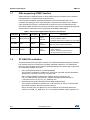
UM1715 User manual Getting started with STM32F072 Discovery kit software development tools Introduction This document describes the software environment recommendations required to build an application using the STM32F072 Discovery kit (32F072BDISCOVERY). The document provides guidelines to novice user on how to build and run a sample example and how to create and build his own application. It has the following structure: the first chapter presents the software and hardware requirements (some toolchains supporting the STM32 families, ST-LINK/V2 installation and firmware package presentation). The second chapter provides step by step guidelines on how to execute and debug an application example using some toolchains: ® IAR Embedded Workbench for ARM (EWARM) by IAR systems, Microcontroller Development Kit for ARM (MDK-ARM) by Keil™, ® TrueSTUDIO by Atollic. Although this user manual does not cover all the topics relevant to software development environments, it demonstrates the first basic steps necessary to get started with the compilers/debuggers and includes references for complementary information. April 2014 DocID025764 Rev 1 1/20 www.st.com Contents UM1715 Contents 1 2 3 2/20 System requirements . . . . . . . . . . . . . . . . . . . . . . . . . . . . . . . . . . . . . . . . 5 1.1 IDEs supporting STM32 families . . . . . . . . . . . . . . . . . . . . . . . . . . . . . . . . 6 1.2 ST-LINK/V2 installation . . . . . . . . . . . . . . . . . . . . . . . . . . . . . . . . . . . . . . . 6 1.3 Firmware package . . . . . . . . . . . . . . . . . . . . . . . . . . . . . . . . . . . . . . . . . . . 7 Executing and debugging firmware using the software toolchains . . . 9 2.1 EWARM toolchain . . . . . . . . . . . . . . . . . . . . . . . . . . . . . . . . . . . . . . . . . . . 9 2.2 MDK-ARM toolchain . . . . . . . . . . . . . . . . . . . . . . . . . . . . . . . . . . . . . . . . . 12 2.3 TrueSTUDIO toolchain . . . . . . . . . . . . . . . . . . . . . . . . . . . . . . . . . . . . . . . 14 Revision history . . . . . . . . . . . . . . . . . . . . . . . . . . . . . . . . . . . . . . . . . . . 19 DocID025764 Rev 1 UM1715 List of tables List of tables Table 1. Table 2. Most used integrated development environments . . . . . . . . . . . . . . . . . . . . . . . . . . . . . . . . 6 Document revision history. . . . . . . . . . . . . . . . . . . . . . . . . . . . . . . . . . . . . . . . . . . . . . . . . . 19 DocID025764 Rev 1 3/20 3 List of figures UM1715 List of figures Figure 1. Figure 2. Figure 3. Figure 4. Figure 5. Figure 6. Figure 7. Figure 8. Figure 9. Figure 10. Figure 11. Figure 12. Figure 13. Figure 14. Figure 15. Figure 16. Figure 17. 4/20 Hardware environment . . . . . . . . . . . . . . . . . . . . . . . . . . . . . . . . . . . . . . . . . . . . . . . . . . . . . 5 Firmware package content . . . . . . . . . . . . . . . . . . . . . . . . . . . . . . . . . . . . . . . . . . . . . . . . . . 8 IAR embedded workbench IDE. . . . . . . . . . . . . . . . . . . . . . . . . . . . . . . . . . . . . . . . . . . . . . . 9 EWARM project successfully compiled. . . . . . . . . . . . . . . . . . . . . . . . . . . . . . . . . . . . . . . . 10 Download and Debug button . . . . . . . . . . . . . . . . . . . . . . . . . . . . . . . . . . . . . . . . . . . . . . . 10 IAR embedded workbench debugger screen . . . . . . . . . . . . . . . . . . . . . . . . . . . . . . . . . . . 11 Go button . . . . . . . . . . . . . . . . . . . . . . . . . . . . . . . . . . . . . . . . . . . . . . . . . . . . . . . . . . . . . . 11 uVision4 IDE . . . . . . . . . . . . . . . . . . . . . . . . . . . . . . . . . . . . . . . . . . . . . . . . . . . . . . . . . . . . 12 MDK-ARM project successfully compiled . . . . . . . . . . . . . . . . . . . . . . . . . . . . . . . . . . . . . . 12 Start/Stop debug session button. . . . . . . . . . . . . . . . . . . . . . . . . . . . . . . . . . . . . . . . . . . . . 13 MDK-ARM debugger screen. . . . . . . . . . . . . . . . . . . . . . . . . . . . . . . . . . . . . . . . . . . . . . . . 13 Run button . . . . . . . . . . . . . . . . . . . . . . . . . . . . . . . . . . . . . . . . . . . . . . . . . . . . . . . . . . . . . 14 TrueSTUDIO workspace launcher dialog box. . . . . . . . . . . . . . . . . . . . . . . . . . . . . . . . . . . 14 Atollic TrueSTUDIO® import source select dialog box . . . . . . . . . . . . . . . . . . . . . . . . . . . . 15 Atollic TrueSTUDIO® import projects dialog box . . . . . . . . . . . . . . . . . . . . . . . . . . . . . . . . 16 TrueSTUDIO® project successfully compiled. . . . . . . . . . . . . . . . . . . . . . . . . . . . . . . . . . . 17 TrueSTUDIO debug window . . . . . . . . . . . . . . . . . . . . . . . . . . . . . . . . . . . . . . . . . . . . . . . . 18 DocID025764 Rev 1 UM1715 1 System requirements System requirements Before running the application, please proceed as follows; 1. Install your preferred Integrated Development Environment (IDE) 2. The ST-LINK/V2 driver is installed automatically. In case of problem, you can install manually the driver from the toolchains install directory (further details are available in Section 1.2: ST-LINK/V2 installation). 3. Download the STM32F072 Discovery firmware from STMicroelectronics website, at www.st.com/stm32f0-discovery 4. Establish the connection with the STM32F072 Discovery board as shown hereafter in Figure 1. Figure 1. Hardware environment The above steps are detailed in the coming sections. To run and develop any firmware applications on your STM32F072 Discovery board, the minimum requirements are as follows: Windows PC (XP, Vista, 7, 8), 'USB type A to Mini-B' cable, used to power the STM32F072 Discovery board (through USB connector CN1) from host PC and connect to the embedded ST-LINK/V2 for debugging and programming. DocID025764 Rev 1 5/20 19 System requirements 1.1 UM1715 IDEs supporting STM32 families STMicroelectronics STM32 families of 32-bit ARM Cortex-M core-based microcontrollers are supported by a complete range of software tools. It encompasses traditional integrated development environments IDEs with C/C++ compilers and debuggers from major third-party companies (free versions up to 64KB of code, depending on partner), completed with innovative tools from STMicroelectronics. The following table includes some general information about some integrated development environments as well as the version supporting the STM32F072B product. Table 1. Most used integrated development environments Toolchain Company Compiler Information(1) Version EWARM IAR Systems ® IAR C/C++ 6.70.2 and later www.iar.com 30-day evaluation edition KickStart edition(16Ko Limitation for Cortex M0) MDK-ARM Keil™ ARMCC 4.73 and later www.keil.com MDK-Lite (32Ko Code size limitation) GNUC 4.3.0 and later www.atollic.com 32Ko Limitation (8Ko on Cortex-M0 and Cortex-M1) 30 day Professional version (Trial) TrueSTUDIO © Atollic 1. Register prior to downloading the toolchain 1.2 ST-LINK/V2 installation The STM32F072 Discovery board includes the ST-LINK/V2 embedded debug tool interface. The interface requires to install the ST-LINK/V2 dedicated USB driver. The STM32F072 Discovery board includes an ST-LINK/V2 embedded debug tool interface that is supported by the following software toolchains: IAR™ Embedded Workbench for ARM (EWARM) The toolchain is installed by default in the C:\Program Files\IAR Systems\Embedded Workbench x.x directory on the PC local hard disk. After installing EWARM, install the ST-LINK/V2 driver by running the STLink_V2_USB.exe from IAR_INSTALL_DIRECTORY]\Embedded Workbench x.x\arm\drivers\ST-Link \ST-Link_V2_USBdriver.exe RealView Microcontroller Development Kit (MDK-ARM) toolchain The toolchain is installed by default in the C:\Keil directory on the PC local hard disk; the installer creates a start menu μVision4 shortcut. When connecting the ST-LINK/V2 tool, the PC detects new hardware and asks to install the ST-LINK_V2_USB driver. The “Found New Hardware wizard” appears and 6/20 DocID025764 Rev 1 UM1715 System requirements guides you through the steps needed to install the driver from the recommended location. Atollic TrueSTUDIO® STM32 The toolchain is installed by default in the C:\Program Files\Atollic directory on the PC local hard disk. The ST-Link_V2_USB.exe is installed automatically when installing the software toolchain. Complementary information on the firmware package content and the STM32F072 Discovery board requirements are available in the user manual UM1674 - Getting started with the STM32F072 Discovery kit. Note: The embedded ST-LINK/V2 supports only SWD interface for STM32 devices. 1.3 Firmware package The STM32F072 Discovery firmware applications, demonstration and IPs examples are provided in one single package and supplied in one single zip file. The extraction of the zip file generates one folder, STM32F072B-Discovery_FW_VX.Y.Z, which contains the following sub folders: DocID025764 Rev 1 7/20 19 System requirements UM1715 Figure 2. Firmware package content Template project: pre-configured project with empty main function to be customized by users. This is helpful to start creating your own application based on the peripherals drivers. Master workspace: Assembly of all projects available within this firmware package. Peripheral examples: Include a set of examples for each peripheral ready to be run. 8/20 DocID025764 Rev 1 UM1715 Executing and debugging firmware using the software toolchains 2 Executing and debugging firmware using the software toolchains 2.1 EWARM toolchain Follow the procedure to compile/link and execute an existing EWARM project. The following steps can be applied to an already existing example, demonstration or template project available at STM32F072 Discovery firmware package available on STMicroelectronics website. First of all, you need to go through firmware/readme.txt file which contains the firmware description and hardware/software requirements. 1. Open the IAR Embedded Workbench® for ARM (EWARM). Figure 3 shows the basic names of the windows referred to in this document. Figure 3. IAR embedded workbench IDE 2. 3. 4. In the File menu, select Open and click Workspace to display the Open Workspace dialog box. Browse to select either an example or demonstration or template workspace file and click Open to launch it in the Project window. In the Project menu, select Rebuild All to compile your project If your project is successfully compiled, the following window in Figure 4 is displayed. DocID025764 Rev 1 9/20 19 Executing and debugging firmware using the software toolchains UM1715 Figure 4. EWARM project successfully compiled To change the project settings (Include and preprocessor defines), go through project options: For ‘Include directories’, select Project>Options…>C/C++ compiler> For pre-processor, define Project>Options…C/C++ compiler>pre-processor> 5. In the IAR Embedded Workbench IDE, from the Project menu, select Download and Debug or alternatively, click on the Download and Debug button the in tool bar, to program the Flash memory and start debugging. Figure 5. Download and Debug button The debugger in the IAR Embedded Workbench can be used to debug source code at C and assembly levels, set breakpoints, monitor individual variables and watch events during the code execution. 10/20 DocID025764 Rev 1 UM1715 Executing and debugging firmware using the software toolchains Figure 6. IAR embedded workbench debugger screen To run your application, from the Debug menu, select Go. Alternatively, click on the Go button in the toolbar to run your application. Figure 7. Go button DocID025764 Rev 1 11/20 19 Executing and debugging firmware using the software toolchains 2.2 UM1715 MDK-ARM toolchain 1. Open Keil MDK-ARM Microcontroller Kit, Figure 8 shows the basic names of the “Keil uVision4” windows referred to in this document. Figure 8. uVision4 IDE 2. 3. 4. In the Project menu, select Open Project. Browse to select either an example or demonstration or template project file and click Open to launch it in the Project window. In the Project menu, select Rebuild All target files to compile your project If your project is successfully compiled, the following window (Figure 9) is displayed. Figure 9. MDK-ARM project successfully compiled 12/20 DocID025764 Rev 1 UM1715 Executing and debugging firmware using the software toolchains If you need to change your project settings (Include and preprocessor defines), go through the project options: For ‘Include directories’, select Project>Options for Target > C/C++ > Include Paths For pre-processor definition Project>Options for Target > C/C++ > Preprocessor symbols > Define 5. In the MDK-ARM IDE, from the Debug menu, select Start/Stop Debug Session or, alternatively, click the Start/Stop Debug Session button in the tool bar to program the Flash memory and begin debugging. Figure 10. Start/Stop debug session button 6. The debugger in the MDK-ARM can be used to debug source code at C and assembly levels, set breakpoints, monitor individual variables and watch events during the code execution. Figure 11. MDK-ARM debugger screen DocID025764 Rev 1 13/20 19 Executing and debugging firmware using the software toolchains UM1715 To run your application, from the Debug menu, select Run. Alternatively, click the Run button in the toolbar to run your application. Figure 12. Run button 2.3 TrueSTUDIO toolchain 1. Open Atollic TrueSTUDIO® for ARM product. The program launches and asks for the Workspace location. Figure 13. TrueSTUDIO workspace launcher dialog box 2. 3. 4. 14/20 Browse to select a TrueSTUDIO workspace of either an example or demonstration or template workspace file and click OK to load it. To load an existing project in the selected workspace, select Import from the File menu to display the Import dialog box. In the Import window, open General, select Existing Projects into Workspace and click Next. DocID025764 Rev 1 UM1715 Executing and debugging firmware using the software toolchains Figure 14. Atollic TrueSTUDIO® import source select dialog box 5. Click Select root directory, browse to the TrueSTUDIO workspace folder DocID025764 Rev 1 15/20 19 Executing and debugging firmware using the software toolchains UM1715 Figure 15. Atollic TrueSTUDIO® import projects dialog box 6. 7. 8. 16/20 In the Projects panel, select the project and click Finish. In the Project Explorer, select the project, open the Project menu, and click Build Project. If your project is successfully compiled, the following messages will be displayed on the Console window. DocID025764 Rev 1 UM1715 Executing and debugging firmware using the software toolchains Figure 16. TrueSTUDIO® project successfully compiled If you need to change the project settings (Include directories and preprocessor defines), go through Project>Properties, select C/C++ Build>Settings from the left panel: For ‘Include directories’ C Compiler>Directories>Include path For pre-processor defines 9. C Compiler>Symbols> Defined symbols To debug and run the application, select the project In the Project Explorer and press F11 to start a debug session (see Figure 17). DocID025764 Rev 1 17/20 19 Executing and debugging firmware using the software toolchains UM1715 Figure 17. TrueSTUDIO debug window The debugger in the Atollic TrueSTUDIO can be used to debug source code at C and assembly levels, set breakpoints, monitor individual variables and watch events during the code execution. To run your application, from the Run menu, select Resume, or alternatively click the Resume button in the toolbar. 18/20 DocID025764 Rev 1 UM1715 3 Revision history Revision history Table 2. Document revision history Date Revision 25-Apr-2014 1 Changes Initial release. DocID025764 Rev 1 19/20 19 UM1715 Please Read Carefully: Information in this document is provided solely in connection with ST products. STMicroelectronics NV and its subsidiaries (“ST”) reserve the right to make changes, corrections, modifications or improvements, to this document, and the products and services described herein at any time, without notice. All ST products are sold pursuant to ST’s terms and conditions of sale. Purchasers are solely responsible for the choice, selection and use of the ST products and services described herein, and ST assumes no liability whatsoever relating to the choice, selection or use of the ST products and services described herein. No license, express or implied, by estoppel or otherwise, to any intellectual property rights is granted under this document. If any part of this document refers to any third party products or services it shall not be deemed a license grant by ST for the use of such third party products or services, or any intellectual property contained therein or considered as a warranty covering the use in any manner whatsoever of such third party products or services or any intellectual property contained therein. UNLESS OTHERWISE SET FORTH IN ST’S TERMS AND CONDITIONS OF SALE ST DISCLAIMS ANY EXPRESS OR IMPLIED WARRANTY WITH RESPECT TO THE USE AND/OR SALE OF ST PRODUCTS INCLUDING WITHOUT LIMITATION IMPLIED WARRANTIES OF MERCHANTABILITY, FITNESS FOR A PARTICULAR PURPOSE (AND THEIR EQUIVALENTS UNDER THE LAWS OF ANY JURISDICTION), OR INFRINGEMENT OF ANY PATENT, COPYRIGHT OR OTHER INTELLECTUAL PROPERTY RIGHT. ST PRODUCTS ARE NOT DESIGNED OR AUTHORIZED FOR USE IN: (A) SAFETY CRITICAL APPLICATIONS SUCH AS LIFE SUPPORTING, ACTIVE IMPLANTED DEVICES OR SYSTEMS WITH PRODUCT FUNCTIONAL SAFETY REQUIREMENTS; (B) AERONAUTIC APPLICATIONS; (C) AUTOMOTIVE APPLICATIONS OR ENVIRONMENTS, AND/OR (D) AEROSPACE APPLICATIONS OR ENVIRONMENTS. WHERE ST PRODUCTS ARE NOT DESIGNED FOR SUCH USE, THE PURCHASER SHALL USE PRODUCTS AT PURCHASER’S SOLE RISK, EVEN IF ST HAS BEEN INFORMED IN WRITING OF SUCH USAGE, UNLESS A PRODUCT IS EXPRESSLY DESIGNATED BY ST AS BEING INTENDED FOR “AUTOMOTIVE, AUTOMOTIVE SAFETY OR MEDICAL” INDUSTRY DOMAINS ACCORDING TO ST PRODUCT DESIGN SPECIFICATIONS. PRODUCTS FORMALLY ESCC, QML OR JAN QUALIFIED ARE DEEMED SUITABLE FOR USE IN AEROSPACE BY THE CORRESPONDING GOVERNMENTAL AGENCY. Resale of ST products with provisions different from the statements and/or technical features set forth in this document shall immediately void any warranty granted by ST for the ST product or service described herein and shall not create or extend in any manner whatsoever, any liability of ST. ST and the ST logo are trademarks or registered trademarks of ST in various countries. Information in this document supersedes and replaces all information previously supplied. The ST logo is a registered trademark of STMicroelectronics. All other names are the property of their respective owners. © 2014 STMicroelectronics - All rights reserved STMicroelectronics group of companies Australia - Belgium - Brazil - Canada - China - Czech Republic - Finland - France - Germany - Hong Kong - India - Israel - Italy - Japan Malaysia - Malta - Morocco - Philippines - Singapore - Spain - Sweden - Switzerland - United Kingdom - United States of America www.st.com 20/20 DocID025764 Rev 1