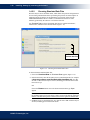
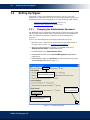
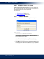
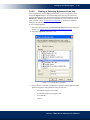
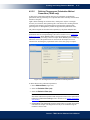
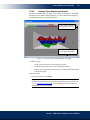
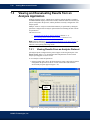
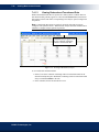
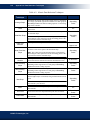
1
Absorbance %XPERTS)N-ICROPLATE!NALYSIS Plate Washing Concert - TRIAD Series Software User’s &RQFHUW75,$'6HULHV6RIWZDUH Manual Luminescence 70 70 8VHU¶V0DQXDO Automated Processing Software Consumables DYNEX Technologies, Inc. 14340 Sullyfield Circle, Chantilly, VA 20151-1621 Phone: (703) 631-7800 FAX: (703) 803-1441 www.dynextechnologies.com ii Revision History Revision Date: April 2005 Catalog No. 61000025 This manual is published by DYNEX Technologies, Inc. Questions or comments regarding the content of this manual can be directed to the address below or to your supplier. DYNEX Technologies, Inc. 14340 Sullyfield Circle Chantilly, VA 20151-1621 USA Telephone: (800) 288-2354, (703) 631-7800 Fax: (703) 803-1441 Website: www.dynextechnologies.com DYNEX Technologies reserves the right to make technical improvements to this equipment and documentation without prior notice as part of a continuous program of product development. This manual supersedes all previous editions. Microsoft® and Windows® are registered trademarks of the Microsoft Corporation. IBM is a trademark of International Business Machines Corporation in the United States, other countries, or both. Pentium is a registered trademark of Intel Corporation. Adobe, Acrobat, and Postscript are either registered trademarks or trademarks of Adobe Systems Incorporated in the United States and/or other countries. All other trademarks appearing in this manual are the property of their respective owners. © 2005 Beckman Coulter, Inc. All rights reserved. DYNEX Technologies, Inc. iii Warranty and Special Provisions Limited Warranty DYNEX Technologies' products are fully guaranteed for one year against defects in parts, materials, and workmanship. Defective parts and materials will be replaced or, at the discretion of DYNEX Technologies, repaired at no charge for a period of one year and labor required for such replacement or repair will be provided at no charge for a period of one year, provided that the products are utilized and maintained in accordance with the instructions in the applicable operating and servicing manual, and provided further that the products have not, as determined solely by DYNEX Technologies, been subject to misuse or abuse by the Customer or other parties unrelated to DYNEX Technologies. DYNEX Technologies makes no warranty, expressed or implied, as to the fitness of any product for any particular purposes other than those purposes described in the applicable operating and servicing manual, nor does DYNEX Technologies make any other warranty, whether expressed or implied, including merchantability, other than those appearing on the face hereof. Where DYNEX Technologies guarantees any product, whether under this Warranty or as a matter of law, and there is a breach of such guarantee, the Customer's only and exclusive remedy shall be the replacement or repair of defective parts and materials, as described above. This shall be the limit of DYNEX Technologies liability. Furthermore, DYNEX Technologies shall not be liable for incidental or consequential damages. Failure of the Customer to notify DYNEX Technologies of a claimed defect by registered mail within thirty days of the discovery thereof shall constitute a waiver of any claim for breach of warranty. When a product is required by DYNEX Technologies to be installed by a DYNEX Technologies engineer or technician, the period of this Warranty shall begin on the date of such installation, provided, however, that any use of the product prior to such installation shall, at the sole election of DYNEX Technologies, void this Warranty. When installation by DYNEX Technologies personnel is not required, the period of this Warranty shall begin on the date of shipment from DYNEX Technologies. The period of this Warranty shall begin as described above whether or not the product has been installed or shipped pursuant to a purchase order, and any trail period shall be deducted from the Warranty period that would otherwise apply under a subsequent placed purchase order for that product. Limitation of Liability. Notwithstanding anything to the contrary contained herein, the liability of SELLER (whether by reason of breach of warranty, breach of contract, tort, or otherwise), including without limitation under any indemnification provision contained herein, shall be limited to replacement of goods returned to DYNEX Technologies which are shown to DYNEX Technologies' reasonable satisfaction to have been nonconforming or to refund the purchase price, or, if not paid, to a credit amount of the purchase price therefore. THE FOREGOING WARRANTIES ARE EXCLUSIVE AND ARE GIVEN AND ACCEPTED IN LIEU OF ANY AND ALL OTHER WARRANTIES, EXPRESS OR IMPLIED, INCLUDING WITHOUT LIMITATION, THE IMPLIED WARRANTY OF MECHANTABILITY AND THE IMPLIED WARRANTY OF FITNESS FOR A PARTICULAR PURPOSE. NEITHER PARTY SHALL BE LIABLE TO THE OTHER FOR ANY INCIDENTAL, INDIRECT, SPECIAL, OR CONSEQUENTIAL DAMAGES. Concert - TRIAD Series Software User’s Manual v Safety Information All Warnings and Cautions in this document include an exclamation point, a lightning bolt, or a light burst symbol framed within a triangle. Please pay special attention to the specific safety information associated with these symbols. WARNING: If the equipment is used in a manner not specified by DYNEX Technologies, Inc., the protection provided by the equipment may be impaired. Warning and Caution Definitions The exclamation point symbol is an international symbol which serves as a reminder that all safety instructions should be read and understood before installation, use, maintenance, and servicing is attempted. When this symbol is displayed in this manual, pay special attention to the specific safety information associated with the symbol. WARNING A WARNING calls attention to a condition or possible situation that could cause injury to the operator. CAUTION A CAUTION calls attention to a condition or possible situation that could damage or destroy the product or the operator’s work. Concert - TRIAD Series Software User’s Manual vi Warnings and Cautions Found in this Manual Please read and observe all cautions and instructions. Remember, the most important key to safety is to use Concert - TRIAD Series Software with care. The WARNINGs and CAUTIONs found within this document are listed below. WARNING: If the equipment is used in a manner not specified by DYNEX Technologies, Inc., the protection provided by the equipment may be impaired. CAUTION: Shake low density plates, such as 6- or 48-well plates, at low speed only. Shaking low density plates at higher speeds may cause liquid in wells to spill. CAUTION: The plate height configured must not be less than that of the actual plate. Doing so may cause the TRIAD optics transport to collide with the plate during a Read Height Optimization. DYNEX Technologies, Inc. vii Table of Contents Safety Information . . . . . . . . . . . . . . . . . . . . . . . . . . . . . . . . . . . . . . . . . . v Table of Contents . . . . . . . . . . . . . . . . . . . . . . . . . . . . . . . . . . . . . . . . . . vii List of Figures . . . . . . . . . . . . . . . . . . . . . . . . . . . . . . . . . . . . . . . . . . . . . xiii List of Tables. . . . . . . . . . . . . . . . . . . . . . . . . . . . . . . . . . . . . . . . . . . . . xvii 1 Installing, Setting Up, and Using the Software 1.1 1.2 1.3 1.4 Overview . . . . . . . . . . . . . . . . . . . . . . . . . . . . . . . . . . . . . . . . . . . . . . . . . . . . . . . . 1-1 Using Concert - TRIAD Series Software . . . . . . . . . . . . . . . . . . . . . . . . . . . . . . . 1-2 1.2.1 Launching the Software . . . . . . . . . . . . . . . . . . . . . . . . . . . . . . . . . . . . . 1-3 1.2.2 Using the Software Interface . . . . . . . . . . . . . . . . . . . . . . . . . . . . . . . . . 1-4 1.2.2.1 About the Navigation Pane . . . . . . . . . . . . . . . . . . . . . . . . . . 1-4 1.2.2.2 About the Toolbar . . . . . . . . . . . . . . . . . . . . . . . . . . . . . . . . . 1-5 1.2.2.3 About the Selection and Configuration Pane . . . . . . . . . . . . 1-5 1.2.3 Accessing Online Help . . . . . . . . . . . . . . . . . . . . . . . . . . . . . . . . . . . . . . 1-5 Installing Concert - TRIAD Series Software . . . . . . . . . . . . . . . . . . . . . . . . . . . . . 1-6 1.3.1 Meeting System Requirements . . . . . . . . . . . . . . . . . . . . . . . . . . . . . . . . 1-6 1.3.2 Installing Concert - TRIAD Series Software on Windows® 2000 or XP . . . . . . . . . . . . . . . . . . . . . . . . . . . . . . . . . . . . . . . . . . . . 1-7 1.3.3 Installing Concert - TRIAD Series Software on Windows NT® . . . . . . 1-9 1.3.4 Installing Optional Modules . . . . . . . . . . . . . . . . . . . . . . . . . . . . . . . . . 1-10 1.3.5 Repairing or Removing the Concert - TRIAD Series Software Installation . . . . . . . . . . . . . . . . . . . . . . . . . . . . . . . . . . . . 1-11 Setting Up Concert - TRIAD Series Software. . . . . . . . . . . . . . . . . . . . . . . . . . . 1-12 1.4.1 Configuring Communication Settings . . . . . . . . . . . . . . . . . . . . . . . . . 1-14 1.4.2 Configuring Software Settings . . . . . . . . . . . . . . . . . . . . . . . . . . . . . . . 1-16 1.4.2.1 Configuring Print Settings . . . . . . . . . . . . . . . . . . . . . . . . . 1-17 1.4.2.2 Choosing Simulated Data Files. . . . . . . . . . . . . . . . . . . . . . 1-18 1.4.2.3 Choosing the Directory Where Exported Measurement Results are Saved . . . . . . . . . . . . . . . . . . . . . 1-19 Concert - TRIAD Series Software User’s Manual viii 2 Setting Up and Controlling Instruments 2.1 2.2 2.3 Overview . . . . . . . . . . . . . . . . . . . . . . . . . . . . . . . . . . . . . . . . . . . . . . . . . . . . . . . . 2-1 Controlling Instrument Actions . . . . . . . . . . . . . . . . . . . . . . . . . . . . . . . . . . . . . . . 2-3 2.2.1 Ejecting the Plate Carrier . . . . . . . . . . . . . . . . . . . . . . . . . . . . . . . . . . . . 2-3 2.2.2 Loading the Plate Carrier . . . . . . . . . . . . . . . . . . . . . . . . . . . . . . . . . . . . 2-3 2.2.3 Initializing the Instrument. . . . . . . . . . . . . . . . . . . . . . . . . . . . . . . . . . . . 2-4 2.2.4 Connecting to the Instrument . . . . . . . . . . . . . . . . . . . . . . . . . . . . . . . . . 2-4 2.2.5 Enabling Simulation Mode . . . . . . . . . . . . . . . . . . . . . . . . . . . . . . . . . . . 2-5 Configuring Instrument Settings . . . . . . . . . . . . . . . . . . . . . . . . . . . . . . . . . . . . . . 2-6 2.3.1 Configuring Basic Instrument Settings. . . . . . . . . . . . . . . . . . . . . . . . . . 2-7 2.3.2 Defining and Editing Filter Slides . . . . . . . . . . . . . . . . . . . . . . . . . . . . . 2-8 2.3.2.1 Adding Filter Slides . . . . . . . . . . . . . . . . . . . . . . . . . . . . . . . 2-9 2.3.2.2 Configuring Filter Slides . . . . . . . . . . . . . . . . . . . . . . . . . . . 2-9 2.3.2.3 Removing Filter Slides . . . . . . . . . . . . . . . . . . . . . . . . . . . . 2-10 2.3.2.4 Exporting and Importing All Filter Slide Configurations . . . . . . . . . . . . . . . . . . . . . . . . . . . . . . . 2-11 2.3.2.5 Exporting and Importing Individual Filter Slide Configurations . . . . . . . . . . . . . . . . . . . . . . . . . . . 2-11 2.3.3 Manually Controlling the Instrument . . . . . . . . . . . . . . . . . . . . . . . . . . 2-12 2.3.3.1 Temperature Control (TRIAD only). . . . . . . . . . . . . . . . . . 2-12 2.3.3.2 Shake Control . . . . . . . . . . . . . . . . . . . . . . . . . . . . . . . . . . . 2-13 2.3.3.3 Plate Control . . . . . . . . . . . . . . . . . . . . . . . . . . . . . . . . . . . . 2-13 2.3.3.4 Excitation and Emission Filter Slide Control . . . . . . . . . . . 2-13 3 Setting Up and Using Signet 3.1 3.2 3.3 3.4 Overview . . . . . . . . . . . . . . . . . . . . . . . . . . . . . . . . . . . . . . . . . . . . . . . . . . . . . . . . 3-1 Setting Up Signet . . . . . . . . . . . . . . . . . . . . . . . . . . . . . . . . . . . . . . . . . . . . . . . . . . 3-2 3.2.1 Changing the Administrator Password . . . . . . . . . . . . . . . . . . . . . . . . . . 3-2 3.2.2 Setting the Signet Support Level . . . . . . . . . . . . . . . . . . . . . . . . . . . . . . 3-3 Performing System Administration Tasks . . . . . . . . . . . . . . . . . . . . . . . . . . . . . . . 3-5 3.3.1 Administering User Accounts and Roles . . . . . . . . . . . . . . . . . . . . . . . . 3-5 3.3.1.1 Configuring Roles for Concert - TRIAD Series Software User Accounts . . . . . . . . . . . . . . . . . . . . . . . . . 3-7 3.3.2 Restoring the Administrator Password . . . . . . . . . . . . . . . . . . . . . . . . . . 3-9 3.3.3 Viewing the System Activity Audit Log . . . . . . . . . . . . . . . . . . . . . . . 3-10 Performing Signet User Actions in Concert - TRIAD Series Software . . . . . . . 3-11 3.4.1 Logging On and Off the System . . . . . . . . . . . . . . . . . . . . . . . . . . . . . . 3-12 3.4.1.1 Logging On the System . . . . . . . . . . . . . . . . . . . . . . . . . . . 3-12 3.4.1.2 Logging Off the System . . . . . . . . . . . . . . . . . . . . . . . . . . . 3-13 3.4.1.3 Handling Disabled Accounts . . . . . . . . . . . . . . . . . . . . . . . 3-13 3.4.2 Changing the Password of the User Currently Logged Into the System. . . . . . . . . . . . . . . . . . . . . . . . . . . . . . . . . . . . . . . . . . . . 3-14 3.4.3 Viewing and Searching the Concert - TRIAD Series Software Audit Log . . . . . . . . . . . . . . . . . . . . . . . . . . . . . . . . . . . . . . . . . . . . 3-15 3.4.4 Reactivating Disabled Message Boxes . . . . . . . . . . . . . . . . . . . . . . . . . 3-16 DYNEX Technologies, Inc. ix 3.4.5 Adding Electronic Signatures and Comments to Items . . . . . . . . . . . . 3.4.5.1 Signing Items . . . . . . . . . . . . . . . . . . . . . . . . . . . . . . . . . . . 3.4.5.2 Viewing or Unlocking Signatures for an Item . . . . . . . . . . 3.4.5.3 Viewing Unlocked Signatures . . . . . . . . . . . . . . . . . . . . . . 3-17 3-18 3-19 3-20 4 Creating and Editing Detection Methods 4.1 4.2 4.3 4.4 4.5 4.6 Overview . . . . . . . . . . . . . . . . . . . . . . . . . . . . . . . . . . . . . . . . . . . . . . . . . . . . . . . . 4-1 Creating Detection Methods . . . . . . . . . . . . . . . . . . . . . . . . . . . . . . . . . . . . . . . . . 4-3 4.2.1 Selecting a Method Technique . . . . . . . . . . . . . . . . . . . . . . . . . . . . . . . . 4-4 4.2.2 Selecting the Method Type . . . . . . . . . . . . . . . . . . . . . . . . . . . . . . . . . . . 4-5 4.2.3 Defining Method Parameters . . . . . . . . . . . . . . . . . . . . . . . . . . . . . . . . . 4-6 4.2.3.1 Defining Absorbance Method Parameters . . . . . . . . . . . . . . 4-6 4.2.3.2 Defining Luminescence Method Parameters . . . . . . . . . . . . 4-7 4.2.3.3 Defining Fluorescence Intensity Top Method Parameters. . . . . . . . . . . . . . . . . . . . . . . . . . . . . . . . . . . . 4-8 4.2.3.4 Defining Fluorescence Intensity Bottom Method Parameters (TRIAD only). . . . . . . . . . . . . . . . . . . . . . . . 4-9 4.2.3.5 Defining Fluorescence Polarization Method Parameters (TRIAD only). . . . . . . . . . . . . . . . . . . . . . . 4-11 4.2.3.6 Defining Time-Resolved Fluorescence Method Parameters (TRIAD only). . . . . . . . . . . . . . . . . . . . . . . 4-12 4.2.4 Signing a Detection Method . . . . . . . . . . . . . . . . . . . . . . . . . . . . . . . . . 4-13 Editing Detection Methods . . . . . . . . . . . . . . . . . . . . . . . . . . . . . . . . . . . . . . . . . 4-14 Copying Detection Methods . . . . . . . . . . . . . . . . . . . . . . . . . . . . . . . . . . . . . . . . 4-16 Deleting Detection Methods . . . . . . . . . . . . . . . . . . . . . . . . . . . . . . . . . . . . . . . . 4-17 Exporting and Importing Detection Methods . . . . . . . . . . . . . . . . . . . . . . . . . . . 4-18 5 Creating and Editing Labware 5.1 5.2 5.3 5.4 5.5 Overview . . . . . . . . . . . . . . . . . . . . . . . . . . . . . . . . . . . . . . . . . . . . . . . . . . . . . . . . 5-1 Creating Labware. . . . . . . . . . . . . . . . . . . . . . . . . . . . . . . . . . . . . . . . . . . . . . . . . . 5-3 5.2.1 Defining Labware Information . . . . . . . . . . . . . . . . . . . . . . . . . . . . . . . . 5-4 5.2.1.1 General Labware Selection Guidelines. . . . . . . . . . . . . . . . . 5-6 5.2.2 Configuring Offsets and Well Dimensions for the Default Labware Lot . . . . . . . . . . . . . . . . . . . . . . . . . . . . . . . . . . . . . . . . . . . 5-7 5.2.3 Signing Labware . . . . . . . . . . . . . . . . . . . . . . . . . . . . . . . . . . . . . . . . . . . 5-8 Editing Labware. . . . . . . . . . . . . . . . . . . . . . . . . . . . . . . . . . . . . . . . . . . . . . . . . . . 5-9 5.3.1 Viewing and Editing Labware Information . . . . . . . . . . . . . . . . . . . . . 5-10 5.3.2 Selecting and Editing Labware Lots . . . . . . . . . . . . . . . . . . . . . . . . . . . 5-11 Copying Labware. . . . . . . . . . . . . . . . . . . . . . . . . . . . . . . . . . . . . . . . . . . . . . . . . 5-12 Deleting Labware. . . . . . . . . . . . . . . . . . . . . . . . . . . . . . . . . . . . . . . . . . . . . . . . . 5-13 Concert - TRIAD Series Software User’s Manual x 5.6 5.7 Optimizing Labware . . . . . . . . . . . . . . . . . . . . . . . . . . . . . . . . . . . . . . . . . . . . . . 5.6.1 Selecting the Detection Method . . . . . . . . . . . . . . . . . . . . . . . . . . . . . . 5.6.2 Preparing and Loading the Labware . . . . . . . . . . . . . . . . . . . . . . . . . . . 5.6.3 Performing the Optimization Read . . . . . . . . . . . . . . . . . . . . . . . . . . . . 5.6.4 Selecting the Centers of the Four Corner Wells . . . . . . . . . . . . . . . . . . 5.6.5 Verifying Well Centers . . . . . . . . . . . . . . . . . . . . . . . . . . . . . . . . . . . . . Exporting and Importing Labware. . . . . . . . . . . . . . . . . . . . . . . . . . . . . . . . . . . . 5-14 5-15 5-16 5-17 5-18 5-19 5-21 6 Creating Protocols 6.1 6.2 6.3 6.4 6.5 6.6 6.7 6.8 Overview . . . . . . . . . . . . . . . . . . . . . . . . . . . . . . . . . . . . . . . . . . . . . . . . . . . . . . . . 6-1 Creating Basic and Analysis Protocols . . . . . . . . . . . . . . . . . . . . . . . . . . . . . . . . . 6-3 6.2.1 Configuring General Settings . . . . . . . . . . . . . . . . . . . . . . . . . . . . . . . . . 6-5 6.2.2 Selecting the Technique Type. . . . . . . . . . . . . . . . . . . . . . . . . . . . . . . . . 6-7 6.2.3 Selecting the Labware Type Used in the Protocol . . . . . . . . . . . . . . . . . 6-8 6.2.4 Configuring Labware Layout Settings . . . . . . . . . . . . . . . . . . . . . . . . . . 6-9 6.2.4.1 Configuring the Sample Layout for Basic Applications. . . . 6-9 6.2.4.2 Configuring the Sample Layout for Analysis Applications . . . . . . . . . . . . . . . . . . . . . . . . . . . . . . . . . . . . 6-11 6.2.4.3 Configuring Reading Direction . . . . . . . . . . . . . . . . . . . . . 6-14 6.2.5 Configuring Detection and Preparation Methods . . . . . . . . . . . . . . . . . 6-15 6.2.5.1 Configuring a Method in Basic Mode . . . . . . . . . . . . . . . . 6-16 6.2.5.2 Configuring a Method in Advanced Mode . . . . . . . . . . . . . 6-23 6.2.6 Configuring Variables (Concert - TRIAD Series Analysis Software only). . . . . . . . . . . . . . . . . . . . . . . . . . . . . . . . . . . . . . . . . 6-31 6.2.7 Configuring a Transformation Formula (Concert - TRIAD Series Analysis Software only). . . . . . . . . . . . . . . . . . . . . . . . . . . . 6-32 6.2.8 Configuring Concentration (Concert - TRIAD Series Analysis Software only). . . . . . . . . . . . . . . . . . . . . . . . . . . . . . . . . . . . . . . . . 6-33 6.2.9 Configuring Cutoff Values (Concert - TRIAD Series Analysis Softwareonly) . . . . . . . . . . . . . . . . . . . . . . . . . . . . . . . . . . . . . . . . . 6-38 6.2.10 Configuring Validation Rules (Concert - TRIAD Series Analysis Software only) . . . . . . . . . . . . . . . . . . . . . . . . . . . . . . . . . 6-40 6.2.11 Configuring Output Settings . . . . . . . . . . . . . . . . . . . . . . . . . . . . . . . . . 6-42 6.2.11.1 Configuring a Program to Execute after a Protocol Run Completes . . . . . . . . . . . . . . . . . . . . . . . . . . . . . . . 6-44 6.2.12 Signing a Protocol. . . . . . . . . . . . . . . . . . . . . . . . . . . . . . . . . . . . . . . . . 6-45 Running Protocols . . . . . . . . . . . . . . . . . . . . . . . . . . . . . . . . . . . . . . . . . . . . . . . . 6-46 6.3.1 Running a Protocol on an Instrument . . . . . . . . . . . . . . . . . . . . . . . . . . 6-46 6.3.1.1 Optimizing Read Height (TRIAD only) . . . . . . . . . . . . . . . 6-48 6.3.2 Running a Protocol When Simulation Mode is Enabled . . . . . . . . . . . 6-51 Editing Protocols . . . . . . . . . . . . . . . . . . . . . . . . . . . . . . . . . . . . . . . . . . . . . . . . . 6-53 Copying Protocols . . . . . . . . . . . . . . . . . . . . . . . . . . . . . . . . . . . . . . . . . . . . . . . . 6-55 Deleting Protocols . . . . . . . . . . . . . . . . . . . . . . . . . . . . . . . . . . . . . . . . . . . . . . . . 6-56 Printing Protocol Configuration Information . . . . . . . . . . . . . . . . . . . . . . . . . . . 6-57 Exporting and Importing Protocols . . . . . . . . . . . . . . . . . . . . . . . . . . . . . . . . . . . 6-59 DYNEX Technologies, Inc. xi 7 Viewing Measurement Results 7.1 7.2 7.3 7.4 7.5 7.6 7.7 Overview . . . . . . . . . . . . . . . . . . . . . . . . . . . . . . . . . . . . . . . . . . . . . . . . . . . . . . . . 7-1 Viewing Measurement Results in the Result Viewer . . . . . . . . . . . . . . . . . . . . . . 7-3 7.2.1 Viewing Raw Data . . . . . . . . . . . . . . . . . . . . . . . . . . . . . . . . . . . . . . . . . 7-4 7.2.2 Viewing Reduced Data . . . . . . . . . . . . . . . . . . . . . . . . . . . . . . . . . . . . . . 7-5 7.2.3 Viewing Mean Data . . . . . . . . . . . . . . . . . . . . . . . . . . . . . . . . . . . . . . . . 7-6 7.2.4 Viewing Graphs . . . . . . . . . . . . . . . . . . . . . . . . . . . . . . . . . . . . . . . . . . . 7-7 7.2.4.1 Viewing Two-Dimensional Graphs . . . . . . . . . . . . . . . . . . . 7-8 7.2.4.2 Viewing Three-Dimensional Graphs . . . . . . . . . . . . . . . . . . 7-9 7.2.5 Recalculating Data Reduction . . . . . . . . . . . . . . . . . . . . . . . . . . . . . . . 7-10 7.2.6 Exporting Measurement Results to Microsoft® Excel. . . . . . . . . . . . . 7-12 7.2.7 Saving Measurement Results . . . . . . . . . . . . . . . . . . . . . . . . . . . . . . . . 7-12 Viewing and Reevaluating Results from an Analysis Application . . . . . . . . . . . 7-14 7.3.1 Viewing Results From an Analysis Protocol . . . . . . . . . . . . . . . . . . . . 7-14 7.3.1.1 Changing the Standard Curve Graph View . . . . . . . . . . . . 7-15 7.3.2 Reevaluating Results from an Analysis Protocol . . . . . . . . . . . . . . . . . 7-17 Viewing Exported Measurement Results . . . . . . . . . . . . . . . . . . . . . . . . . . . . . . 7-19 7.4.1 Viewing Measurement Results in Microsoft® Excel . . . . . . . . . . . . . . 7-19 7.4.1.1 Viewing Protocol and Measurement Information . . . . . . . 7-20 7.4.1.2 Viewing Raw Data . . . . . . . . . . . . . . . . . . . . . . . . . . . . . . . 7-21 7.4.1.3 Viewing Reduced and Transformed Data. . . . . . . . . . . . . . 7-22 Signing Measurement Results . . . . . . . . . . . . . . . . . . . . . . . . . . . . . . . . . . . . . . . 7-23 Deleting Measurement Results . . . . . . . . . . . . . . . . . . . . . . . . . . . . . . . . . . . . . . 7-24 Printing Measurement Results . . . . . . . . . . . . . . . . . . . . . . . . . . . . . . . . . . . . . . . 7-25 A Appendix A: Data Reduction Techniques A.1 Supported Data Reduction Techniques . . . . . . . . . . . . . . . . . . . . . . . . . . . . . . . . . A-1 B Appendix B: Mathematical Operators and Functions B.1 Supported Mathematical Operators and Functions . . . . . . . . . . . . . . . . . . . . . . . . B-1 C Appendix C: Software Error Codes C.1 Troubleshooting Software Error Codes . . . . . . . . . . . . . . . . . . . . . . . . . . . . . . . . . C-1 Index. . . . . . . . . . . . . . . . . . . . . . . . . . . . . . . . . . . . . . . . . . . . . . . . . . . . . xix Concert - TRIAD Series Software User’s Manual xiii List of Figures Figure 1-1. Concert - TRIAD Series Software main window ..................................................... 1-3 Figure 1-2. Using online help ...................................................................................................... 1-5 Figure 1-3. Starting the installation ............................................................................................. 1-8 Figure 1-4. Installing the software on a Windows NT® system ................................................. 1-9 Figure 1-5. Repairing the installation ........................................................................................ 1-11 Figure 1-6. Concert - TRIAD Series Software main screen ...................................................... 1-12 Figure 1-7. Warning — Instrument is not connected ................................................................ 1-13 Figure 1-8. Instrument Selection List with simulated instrument selected................................ 1-14 Figure 1-9. Configuring communications settings .................................................................... 1-15 Figure 1-10. Configuring Software Settings.............................................................................. 1-16 Figure 1-11. Configuring Print Settings .................................................................................... 1-17 Figure 1-12. Choosing the Simulated Data files........................................................................ 1-18 Figure 1-13. Choosing the directory where data is saved.......................................................... 1-19 Figure 2-1. Instrument Selection List .......................................................................................... 2-2 Figure 2-2. Instrument Settings — Basic Settings....................................................................... 2-7 Figure 2-3. Instrument Settings — Filter Slides .......................................................................... 2-8 Figure 2-4. Configuring filter properties ..................................................................................... 2-9 Figure 2-5. Instrument Settings — Manual Control .................................................................. 2-12 Figure 3-1. Account Management ............................................................................................... 3-2 Figure 3-2. Support Options ........................................................................................................ 3-4 Figure 3-3. Account Management ............................................................................................... 3-6 Figure 3-4. Configuring roles ...................................................................................................... 3-7 Figure 3-5. Password Restore ...................................................................................................... 3-9 Figure 3-6. Signet Audit Log ..................................................................................................... 3-10 Figure 3-7. Accessing user actions ............................................................................................ 3-11 Figure 3-8. Logon ...................................................................................................................... 3-12 Figure 3-9. Administrator Notification ...................................................................................... 3-13 Figure 3-10. Changing the user password ................................................................................. 3-14 Figure 3-11. Viewing records in the Audit Viewer ................................................................... 3-15 Figure 3-12. Activating disabled messages ............................................................................... 3-16 Figure 3-13. Signing an item ..................................................................................................... 3-17 Concert - TRIAD Series Software User’s Manual xiv Figure 3-14. Viewing active signatures ..................................................................................... 3-19 Figure 3-15. Viewing unlocked signatures ................................................................................ 3-20 Figure 4-1. Accessing detection method actions ......................................................................... 4-2 Figure 4-2. Selecting a Method Technique.................................................................................. 4-4 Figure 4-3. Selecting an absorbance Method Type ..................................................................... 4-5 Figure 4-4. Defining absorbance measurement parameters......................................................... 4-6 Figure 4-5. Defining luminescence measurement parameters..................................................... 4-7 Figure 4-6. Defining fluorescence intensity top method parameters........................................... 4-8 Figure 4-7. Defining fluorescence intensity bottom method parameters..................................... 4-9 Figure 4-8. Defining fluorescence polarization method parameters.......................................... 4-11 Figure 4-9. Defining time-resolved fluorescence method parameters....................................... 4-12 Figure 4-10. Editing a fluorescence intensity top method ......................................................... 4-14 Figure 4-11. Confirming the deletion of a detection method .................................................... 4-17 Figure 4-12. Choosing the folder where an exported detection method will be saved.............. 4-18 Figure 5-1. Accessing labware actions ........................................................................................ 5-2 Figure 5-2. Defining plate dimensions and information.............................................................. 5-4 Figure 5-3. Defining offsets and well dimensions ....................................................................... 5-7 Figure 5-4. Editing labware dimensions and well information ................................................. 5-10 Figure 5-5. Configuring offsets and well dimensions in Labware Lots .................................... 5-11 Figure 5-6. Confirming a labware deletion................................................................................ 5-13 Figure 5-7. Selecting the detection method for labware optimization....................................... 5-15 Figure 5-8. Preparing the labware for optimization................................................................... 5-16 Figure 5-9. Labware optimization in progress........................................................................... 5-17 Figure 5-10. Selecting the well center ....................................................................................... 5-18 Figure 5-11. Verifying well centers ........................................................................................... 5-19 Figure 5-12. Choosing the folder where exported labware will be saved ................................. 5-21 Figure 6-1. Protocol Selection List .............................................................................................. 6-2 Figure 6-2. Selecting the application type ................................................................................... 6-4 Figure 6-3. Defining a protocol name and entering notes about the protocol ............................. 6-5 Figure 6-4. Selecting the measurement technique for a TRIAD ................................................. 6-7 Figure 6-5. Selecting the type of labware used in the protocol ................................................... 6-8 Figure 6-6. Configuring Layout Settings for a Basic application................................................ 6-9 Figure 6-7. Configuring Layout Settings for an Analysis application....................................... 6-11 Figure 6-8. Selecting how wells on the plate are read ............................................................... 6-14 Figure 6-9. Configuring a detection method in Method Selection ............................................ 6-15 Figure 6-10. Configuring a method in basic mode .................................................................... 6-16 Figure 6-11. Selecting a data reduction method for a kinetic measurement.............................. 6-18 Figure 6-12. Configuring an area scan....................................................................................... 6-20 Figure 6-13. Configuring a linear scan ...................................................................................... 6-21 Figure 6-14. Selecting a data reduction method for a scan method........................................... 6-22 Figure 6-15. Configuring a method in advanced mode ............................................................. 6-23 Figure 6-16. Adding a kinetic detection method ....................................................................... 6-24 Figure 6-17. Configuring Loop Properties for a kinetic measurement...................................... 6-25 Figure 6-18. Selecting a data reduction method for the sequence ............................................. 6-26 Figure 6-19. Configuring a Shake preparation method ............................................................. 6-28 Figure 6-20. Configuring a Set Temperature preparation method............................................. 6-29 DYNEX Technologies, Inc. xv Figure 6-21. Configuring variables in an analysis protocol....................................................... 6-31 Figure 6-22. Configuring a transformation formula .................................................................. 6-32 Figure 6-23. Configuring concentration parameters.................................................................. 6-33 Figure 6-24. Configuring standards ........................................................................................... 6-36 Figure 6-25. Configuring standard curve validation parameters ............................................... 6-37 Figure 6-26. Configuring cutoff values ..................................................................................... 6-38 Figure 6-27. Configuring validation rules ................................................................................. 6-40 Figure 6-28. Configuring output settings................................................................................... 6-42 Figure 6-29. Configuring an external software application in Output Settings......................... 6-44 Figure 6-30. Preparing to run a protocol on an instrument........................................................ 6-46 Figure 6-31. Selecting the detection method used in the read height optimization................... 6-48 Figure 6-32. Selecting the well read in the read height optimization ........................................ 6-49 Figure 6-33. Read height optimization in progress.................................................................... 6-50 Figure 6-34. Read height optimization completed..................................................................... 6-50 Figure 6-35. Preparing to run a protocol in simulation mode.................................................... 6-51 Figure 6-36. Editing an absorbance protocol............................................................................. 6-53 Figure 6-37. Confirming the deletion of a protocol................................................................... 6-56 Figure 6-38. Previewing a protocol configuration and sample layout printout ......................... 6-58 Figure 6-39. Choosing the folder where an exported protocol will be saved ............................ 6-59 Figure 7-1. Accessing measurement result actions...................................................................... 7-1 Figure 7-2. Viewing results of an area scan measurement .......................................................... 7-3 Figure 7-3. Viewing raw data for an area scan measurement...................................................... 7-4 Figure 7-4. Viewing reduced data for a measurement performed in a multiwavelength protocol .................................................................................... 7-5 Figure 7-5. Viewing mean data for a fluorescence polarization measurement............................ 7-6 Figure 7-6. Viewing kinetic measurement graphs ....................................................................... 7-7 Figure 7-7. Viewing a two-dimensional absorbance graph ......................................................... 7-8 Figure 7-8. Viewing a three-dimensional area scan graph .......................................................... 7-9 Figure 7-9. Changing data reduction parameters in the Results Viewer ................................... 7-10 Figure 7-10. Selecting a data reduction method for the sequence ............................................. 7-11 Figure 7-11. Choosing to overwrite existing measurement results ........................................... 7-12 Figure 7-12. Entering a new name for saved results.................................................................. 7-13 Figure 7-13. Saving parameters edited in the Result Viewer to the protocol ............................ 7-13 Figure 7-14. Viewing existing transformation parameters in the Results Viewer..................... 7-14 Figure 7-15. Viewing existing transformation parameters in the Results Viewer..................... 7-17 Figure 7-16. Editing transformation parameters in the Results Viewer .................................... 7-18 Figure 7-17. Viewing protocol information in the General worksheet (excerpt) ...................... 7-20 Figure 7-18. Viewing raw data (excerpt)................................................................................... 7-21 Figure 7-19. Viewing reduced data (excerpt) ............................................................................ 7-22 Figure 7-20. Confirming the deletion of measurement results .................................................. 7-24 Figure 7-21. Previewing a measurement results printout .......................................................... 7-25 Concert - TRIAD Series Software User’s Manual xvii List of Tables Table 1-1. Host Computer System Requirements ....................................................................... 1-6 Table 2-1. Basic Settings Read-Only Fields ................................................................................ 2-7 Table 3-1. Concert - TRIAD Series Software Permissions ......................................................... 3-8 Table 3-2. Concert - TRIAD Series Software Default Roles....................................................... 3-8 Table 3-3. Audit Log Actions .................................................................................................... 3-16 Table 5-1. General Microplate selection guidelines .................................................................... 5-6 Table 6-1. Curve Fitting Methods.............................................................................................. 6-34 Table 6-2. Example test validation formulas ............................................................................. 6-41 Table 6-3. Output Options ......................................................................................................... 6-43 Table 7-1. Measurement Results Search Options ........................................................................ 7-2 Table 7-2. Well Status Indicators ................................................................................................ 7-4 Table 7-3. Measurement Results Tabs Displayed for Analysis Options ................................... 7-15 Table 7-4. Standard Curve Graph View Options....................................................................... 7-16 Table A-1. Scan Measurement and Sequence Data Reduction Techniques .............................. A-1 Table A-2. Kinetic Data Reduction Techniques ........................................................................ A-2 Table A-3. Fluorescence Polarization Data Reduction Techniques (TRIAD only) .................. A-3 Table B-1. Mathematical and Logical Operators.........................................................................B-1 Table B-2. Mathematical Functions.............................................................................................B-2 Table C-1. Software Error Codes and Solutions..........................................................................C-1 Concert - TRIAD Series Software User’s Manual 1-1 1 1.1 Installing, Setting Up, and Using the Software Overview Concert - TRIAD Series Software configures and controls all measurement protocols and actions performed by the TRIAD LT and TRIAD Multimode Detectors. The software supports performing absorbance, glow luminescence, fluorescence intensity (top and bottom), fluorescence polarization, and time-resolved fluorescence (TRF) measurements. The measurement methods available to users depend on the capabilities of the instrument being controlled. Measurement results may be viewed in Concert - TRIAD Series Software or easily exported to compatible applications such as Microsoft® Excel. Optional modules may be purchased separately to extend the functionality of the software. Available modules include Concert - TRIAD Series Analysis Software, which provides advanced protocol configuration and evaluation capabilities and Concert - TRIAD Series Analysis Software with Signet, which adds support for electronic signature regulations such as 21 CFR Part 11. The simple interface divides the main window into three basic sections, which provide easy access to system functionality. Most operations use a wizard-type interface to efficiently guide the task being performed. This user’s manual covers the functionality provided by Concert - TRIAD Series Software, and the optional Concert - TRIAD Series Analysis Software and Concert TRIAD Series Analysis Software with Signet modules, including: • Setting Up and Controlling Instruments (Chapter 2). • Setting Up and Using Signet (Chapter 3). • Creating and Editing Detection Methods (Chapter 4). • Creating and Editing Labware (Chapter 5). • Creating Protocols (Chapter 6). • Viewing Measurement Results (Chapter 7). This chapter introduces users to the software and provides instructions for: • Using Concert - TRIAD Series Software (Section 1.2). • Installing Concert - TRIAD Series Software (Section 1.3). • Setting Up Concert - TRIAD Series Software (Section 1.4). Concert - TRIAD Series Software User’s Manual 1-2 1.2 Installing, Setting Up, and Using the Software Using Concert - TRIAD Series Software Concert - TRIAD Series Software uses a simple interface that divides the main window into three basic sections: navigation pane, toolbar, and selection and configuration pane (Figure 1-1). The interface includes easy access to the selection lists that provide system functionality and a comprehensive, context-sensitive online help system. This section covers: DYNEX Technologies, Inc. • Launching the Software (Section 1.2.1). • Using the Software Interface (Section 1.2.2). • Accessing Online Help (Section 1.2.3). Installing, Setting Up, and Using the Software 1.2.1 1-3 Launching the Software To launch Concert - TRIAD Series Software: From the Windows® Start menu, choose Programs>Dynex Technologies>Concert - TRIAD Series>Concert - TRIAD Series. Concert - TRIAD Series Software appears (Figure 1-1). Note: If Concert - TRIAD Series Software is not found in the Start menu, the software may have been installed for a single user account on the system instead of all accounts. Check with the site system administrator or login to the user account with permission to access the software. Refer to Section 1.3.2, Installing Concert - TRIAD Series Software on Windows® 2000 or XP, for more information about installing the software for a single or multiple user accounts. Toolbar Links to Selection Lists Selection and configuration pane Navigation pane Figure 1-1. Concert - TRIAD Series Software main window Concert - TRIAD Series Software User’s Manual 1-4 Installing, Setting Up, and Using the Software 1.2.2 Using the Software Interface Concert - TRIAD Series Software uses a simple interface that is divided into three basic sections: • navigation pane (refer to Section 1.2.2.1, About the Navigation Pane). • toolbar (refer to Section 1.2.2.2, About the Toolbar). • selection and configuration pane (refer to Section 1.2.2.3, About the Selection and Configuration Pane). The navigation pane provides access to the selection lists that provide the majority of the functionality built into the software. The options available in the toolbar and configuration pane are determined by the selection list currently selected in the navigation pane. 1.2.2.1 About the Navigation Pane The navigation pane is the narrow pane on the left of the Concert - TRIAD Series Software window (Figure 1-1). Use the navigation pane to switch between selection lists: DYNEX Technologies, Inc. • Protocols — opens the Protocol Selection List and provides the ability to define, run, edit, copy, delete, and print measurement protocols (refer to Chapter 6, Creating Protocols). • Results — opens the Results Selection List and provides the ability to view saved measurement results and modify data reduction parameters in the Result Viewer. When the optional Concert - TRIAD Series Analysis Software module is installed, measurement results may be reevaluated using parameters different from those configured in the original protocol (refer to Chapter 7, Viewing Measurement Results). • Labware — opens the Labware Selection List and provides the ability to create, edit, optimize, copy, and delete labware types (refer to Chapter 5, Creating and Editing Labware). • Detection Methods — opens the Detection Method Selection List and provides the ability to create, edit, copy, and delete detection methods (refer to Chapter 4, Creating and Editing Detection Methods). • Instruments — opens the Instrument Selection List and provides the ability to manually control instrument actions, such as shaking, and configure communications settings and filter slides (refer to Chapter 2, Setting Up and Controlling Instruments). • Software Settings — configures software settings, including system language, print options, default simulated data files, and the directory where measurement results are saved (refer to Section 1.4.2, Configuring Software Settings). • Users — appears in the navigation pane only when the optional Concert TRIAD Series Analysis Software with Signet module is installed and enabled on the system. Signet is an integrated set of features that help Concert - TRIAD Series Software users comply with electronic signature regulations, such as 21 CFR Part 11 (refer to Section 3.4, Performing Signet User Actions in Concert - TRIAD Series Software). Installing, Setting Up, and Using the Software 1.2.2.2 1-5 About the Toolbar The toolbar provides easy access to common software actions. The module chosen in the navigation pane determines which actions are available on the toolbar; for example, Optimize Labware is only available when the Labware module is active. 1.2.2.3 About the Selection and Configuration Pane The selection and configuration pane is the large pane to the right of the navigation pane. Options available in this pane change depending on which module is currently selected in the navigation pane. For example, when Protocols is selected, the Protocol Selection List is displayed, which provides access to configured protocols and functionality specific to the Protocols module. 1.2.3 Accessing Online Help Concert - TRIAD Series Software contains a detailed online help system that covers defining and editing labware, detection methods, and protocols, performing measurements, and exporting measurement results. The online help is context sensitive, which provides instant access to help for the active screen. To access online help: Press F1 at any time to display online help for the active screen (Figure 1-2). OR From the Help menu, choose Help to display the table of contents. Figure 1-2. Using online help Concert - TRIAD Series Software User’s Manual 1-6 1.3 Installing, Setting Up, and Using the Software Installing Concert - TRIAD Series Software The Concert - TRIAD Series Software installer provides the ability to install the software on a new system. Installing the software requires: • Meeting System Requirements (Section 1.3.1). • Installing Concert - TRIAD Series Software on Windows® 2000 or XP (Section 1.3.2). OR • Installing Concert - TRIAD Series Software on Windows NT® (Section 1.3.3). Note: The installation procedure varies depending on the operating system in use on the target system. Follow the instructions in the appropriate section to install the software. • Installing Optional Modules (Section 1.3.4). 1.3.1 Meeting System Requirements To install and use the software successfully, the host computer must meet the minimum system requirements listed in Table 1-1. Where relevant, Table 1-1 also lists recommended specifications. Table 1-1. Host Computer System Requirements Component DYNEX Technologies, Inc. Minimum Requirements CPU Pentium® II 300 Mhz RAM 128 MB minimum 256 MB recommended Hard Drive 300 MB free space CD-ROM Drive 4X Monitor 800x600 resolution Keyboard 101 key Mouse IBM® compatible Serial Port 1 free serial port Operating Systems Windows NT® 4 (Service Pack 6a) Windows® 2000 (Service Pack 1) Windows® XP (Service Pack 1) Installing, Setting Up, and Using the Software 1-7 Table 1-1. Host Computer System Requirements Component Minimum Requirements Operating System Language English (U.S.) Database Microsoft SQL Server 8.0 (Personal Edition included on the installation CD) Note: The storage limit for SQL Server Personal Edition is 2GB. Contact DYNEX Technologies Sales or Customer Technical Support if more storage is required. Web Browser 1.3.2 Internet Explorer 6.0 or later (included on the installation CD) Installing Concert - TRIAD Series Software on Windows® 2000 or XP On a Windows® 2000 or XP system, the Concert - TRIAD Series Software installer uses a simple interface to guide the installation of the software and required components. To install the verification plate software: 1. Exit all Windows programs before running the setup program. 2. Make sure the current user account has Administrator privileges. Accounts with Standard or Restricted access are not permitted to run the setup program. Contact the site system administrator for more information about account privileges. 3. Insert the installation CD into the CD-ROM drive and browse to the contents of the CD. 4. In the contents of the CD, open Begin here for XP or W2K systems. 5. In Begin here for XP or W2K systems, double-click Installer.exe. Concert TRIAD Series Software Installer appears (Figure 1-3). All components required to successfully install the software are listed. The current status of each required component is listed: • a check icon indicates the correct version of the component is already installed on the system. • a caution icon indicates that an older version of the component is installed and must be updated before the software may be installed. • an X icon indicates that the component must be installed before the software may be installed. Concert - TRIAD Series Software User’s Manual 1-8 Installing, Setting Up, and Using the Software Figure 1-3. Starting the installation 6. Choose Update or Install for the first component indicated. Components are installed one at a time and should be installed in the order listed. 7. Follow the steps in the component installer until the component installation is complete. Note: If a component installation requires restarting the system, restart before installing the next component listed. After the system restarts, browse to the contents of the installer CD and launch the installer again to continue installing components. 8. Repeat steps 6 and 7 for each component required. When all components are installed properly, the Install Concert - TRIAD Series Software button activates. 9. Choose Install Concert - TRIAD Series Software to launch the software installation wizard and follow the steps in the wizard. 10. In Concert - TRIAD Series Software Installer, choose Finish. The software is now ready for use. DYNEX Technologies, Inc. Installing, Setting Up, and Using the Software 1.3.3 1-9 Installing Concert - TRIAD Series Software on Windows NT® When installing the software on a Windows NT® system, required components that must be installed before the software are selected manually from a link on a web page (Figure 1-4). To install the verification plate software: 1. Exit all Windows programs before running the setup program. 2. Make sure the current user account has Administrator privileges. Accounts with Standard or Restricted access are not permitted to run the setup program. Contact the site system administrator for more information about account privileges. 3. Insert the installation CD into the CD-ROM drive and browse to the contents of the CD. 4. In the contents of the CD, open Begin here for NT systems. 5. In Begin here for NT systems, double-click Installer.htm. Concert - TRIAD Series Software opens in a web browser window (Figure 1-4). A series of links lists all of the components that must be installed to enable the verification plate. Figure 1-4. Installing the software on a Windows NT® system Concert - TRIAD Series Software User’s Manual 1-10 Installing, Setting Up, and Using the Software 6. Click on a link to launch the installer for that component. During installation, keep in mind that: • the components must be installed in the order listed. • when an installer requires restarting the computer, the computer must be restarted before installing the next component in the list. Note: After the system restarts, browse to the contents of the installer CD and open Installer.htm again to continue installing components. Note: If a prompt to Run or Save the installer appears before the installation wizard, choose Run to start the wizard. 7. Follow the steps in the component installer until the installation is complete. 8. Repeat steps 6 and 7 until all components and Concert - TRIAD Series Software are installed. The software is now ready for use. 1.3.4 Installing Optional Modules Optional modules that extend the functionality of Concert - TRIAD Series Software may be purchased separately and installed on the system. Optional modules use an installation system that is nearly identical to the Concert - TRIAD Series Software installer. To install an optional module: 1. Exit all Windows programs. 2. Make sure the user currently logged into Windows has Administrator privileges. Accounts with Standard or Restricted access are not permitted to install the software. Contact the site system administrator for more information about account privileges. 3. Insert the module installation CD into the CD-ROM drive and browse to the contents of the CD. 4. If installing the module on a Windows® XP or 2000 system, open Begin here for XP or W2K systems. The module installer appears. OR If installing the module on a Windows NT® system, open Begin here for NT systems. A list of components that must be installed appears in a web browser window. 5. If installing on a Windows® XP or 2000 system, Install or Update each required component listed as such, then install the module. OR If installing on a Windows NT® system, install the required components in the order listed, then install the module. DYNEX Technologies, Inc. Installing, Setting Up, and Using the Software 1.3.5 1-11 Repairing or Removing the Concert TRIAD Series Software Installation The Concert - TRIAD Series Software installation may be repaired if required components are missing or damaged. Try repairing the installation if the software will not open or does not run correctly. The software may also be removed (uninstalled) from the system. Repair and removal options are accessed from the Add or Remove Programs control panel in Windows. To repair or remove the software: 1. Exit all open Windows programs. 2. Make sure the current user account has Administrator privileges. Accounts with Standard or Restricted access are not permitted to modify or remove software. Contact the site system administrator for more information about account privileges. 3. If repairing the installation, insert the Concert - TRIAD Series Software installation CD into the CD-ROM drive. 4. From the Start menu, choose Settings>Control Panel. Control Panel appears. 5. In Control Panel, choose Add or Remove Programs. Add or Remove Programs appears. 6. In Add or Remove Programs, choose Multimode Detection Software. Repair and removal options for the software appear. 7. To repair the installation, choose Click here for support information. Support Info appears (Figure 1-5). Proceed to step 8. OR To remove the software, choose Remove and follow the onscreen instructions until the removal process is finished. Note: When removing the software, only files installed during the initial installation are removed. The software database and files created after the installation, such as exported measurement results, remain. Figure 1-5. Repairing the installation 8. In Support Options, choose Repair to search for and automatically reinstall any missing or damaged files required to run the software. 9. When the repair is complete, choose Close. Concert - TRIAD Series Software User’s Manual 1-12 1.4 Installing, Setting Up, and Using the Software Setting Up Concert - TRIAD Series Software After installing the software and physically connecting the instrument to a serial port on the host computer, communications and software settings must be set up. Setting up the software includes: • Configuring Communication Settings (Section 1.4.1). • Configuring Software Settings (Section 1.4.2). To set up Concert - TRIAD Series Software: 1. From the Windows® Start menu, choose Programs>Dynex Technologies>Concert - TRIAD Series>Concert - TRIAD Series. Concert - TRIAD Series Software appears (Figure 1-6). Note: If Concert - TRIAD Series Software is not found in the Start menu, the software may have been installed for a single user account on the system instead of all accounts. Check with the site system administrator or login to the user account with permission to access the software. Refer to Section 1.3.2, Installing Concert - TRIAD Series Software on Windows® 2000 or XP, for more information about installing the software for a single or multiple user accounts. Figure 1-6. Concert - TRIAD Series Software main screen DYNEX Technologies, Inc. Installing, Setting Up, and Using the Software 1-13 2. If the Protocol Selection List (Figure 1-6) appears immediately, the instrument was automatically detected by the software. Proceed to Section 1.4.2, Configuring Software Settings, to configure system settings. OR If Warning appears (Figure 1-7), the instrument was not detected by the software. Choose OK to work in simulation mode until the communications settings are configured properly. Figure 1-7. Warning — Instrument is not connected 3. If the instrument was not detected, configure the communications settings following the steps in Section 1.4.1, Configuring Communication Settings. 4. Configure system settings, such as printing options, following the steps in Section 1.4.2, Configuring Software Settings. Concert - TRIAD Series Software User’s Manual 1-14 Installing, Setting Up, and Using the Software 1.4.1 Configuring Communication Settings After physically connecting the instrument to a serial communications port on the host computer, the selected serial port and communication speed must be configured correctly before Concert - TRIAD Series Software can control instrument actions. Communication settings are configured in Instrument Settings. Before communication with an instrument is configured, a simulated instrument appears in the Instrument Selection List (Figure ). When communication is configured correctly and the instrument is detected by the software, the simulated instrument is replaced in the list by the connected instrument. Note: When Signet is enabled on the system, only users assigned a role containing the Instrument Settings permission may configure instrument settings. Refer to Section 3.3.1.1, Configuring Roles for Concert - TRIAD Series Software User Accounts, for more information about roles and permissions. To configure communications settings: 1. From the navigation pane, choose Instruments. The Instrument Selection List appears (Figure ). Simulated instrument Figure 1-8. Instrument Selection List with simulated instrument selected DYNEX Technologies, Inc. Installing, Setting Up, and Using the Software 1-15 2. From the toolbar, choose Instrument Settings. Instrument Settings appears (Figure 1-9). OR From the Actions menu, choose Instrument Settings. Instrument information fields Figure 1-9. Configuring communications settings 3. Select the Basic Settings tab, if necessary. 4. In Port, select the serial communications port on the host computer that connects to the instrument. 5. In Baudrate, select 38400. 6. Choose Apply to detect the instrument. When the instrument is detected, the instrument information fields are autopopulated with information about the connected instrument. Refer to Table 2-1 for more information about each field. 7. Choose OK to close Instrument Settings. Concert - TRIAD Series Software User’s Manual 1-16 Installing, Setting Up, and Using the Software 1.4.2 Configuring Software Settings Concert - TRIAD Series Software can be customized using the options available in Software Settings (Figure 1-10). Use the tabs in Software Settings to configure printout options, default simulated data files, and the directory where measurement results are stored. To configure Software Settings: 1. From the navigation pane, choose Software Settings. Software Settings appears (Figure 1-10). Software Settings Figure 1-10. Configuring Software Settings 2. Configure the settings in the desired tab(s): DYNEX Technologies, Inc. • Configuring Print Settings (Section 1.4.2.1). • Choosing Simulated Data Files (Section 1.4.2.2). • Choosing the Directory Where Exported Measurement Results are Saved (Section 1.4.2.3). Installing, Setting Up, and Using the Software 1.4.2.1 1-17 Configuring Print Settings Measurement results and protocol configurations may be printed. Printing parameters, such as headers and footers are configured in the Print Settings tab (Figure 1-11). Figure 1-11. Configuring Print Settings To configure print settings: 1. Choose the Print Settings tab. Print Settings appears (Figure 1-11). 2. In Print Header, enter text for each header Line, as desired. Header lines may be left blank. 3. In Footer, enter text for the Footer and Comment, as desired. The comment appears on printed pages below the footer. The footer and comment may be left blank. 4. In Print Options, select Print Preview to preview the page layout onscreen each time a protocol configuration or measurement results are printed. 5. In Print Options, choose Show printer settings to display printing options each time a protocol or measurement results are printed. 6. In Print Options, select the desired Font and Font Size for printed text. 7. Choose Apply to save the new print settings. Concert - TRIAD Series Software User’s Manual 1-18 Installing, Setting Up, and Using the Software 1.4.2.2 Choosing Simulated Data Files Protocols may be run in simulation mode, which allows the protocol configuration to be tested using simulated data before performing the protocol on actual samples. In simulation mode, all features for the instrument type currently selected in the Instrument Selection List are available, but measurement results are either randomly generated by the software or read from a data file. Use Simulated Data to choose the default data files for simulated absorbance, luminescence, and fluorescence measurements (Figure 1-12). Browse for desired data files Figure 1-12. Choosing the Simulated Data files To choose different simulated data files: 1. Choose the Simulated Data tab. Simulated Data appears (Figure 1-12). 2. In the desired field, enter the full path to the new simulated data file; for example, c:\detection software templates\DefaultSimulatedData.dat. Any data file with a .dat extension may be selected, including prior measurement results. Proceed to step 5. OR Choose the Browse button next to the desired measurement type. Open appears. Note: Simulated data files are used when the number of measurement points in the simulated protocol run is the same as those present in the data file. When the number of measurement points is different, the software generates random data. 3. In Open, browse to desired data file. Any data file with a .dat extension may be selected, including prior measurement results. DYNEX Technologies, Inc. Installing, Setting Up, and Using the Software 1-19 4. Choose Open to select the data file and return to Software Settings. OR Choose Cancel to close Open without selecting a different data file. 5. Repeat steps 2 – 4 for each simulated data file desired to change. 6. Choose Apply to set the new default data file(s). 1.4.2.3 Choosing the Directory Where Exported Measurement Results are Saved Exported measurement results files, regardless of format, are saved in a single directory. The default storage directory is C:\Documents and Settings\All Users\Application Data\Multimode\Detection Software\data\. Use Directory Settings to change the storage directory, if desired (Figure 1-13). Note: All measurement results are also stored in the Concert - TRIAD Series Software database and may be accessed using the Result Viewer (refer to Section 7.2, Viewing Measurement Results in the Result Viewer). Browse for desired storage directory Figure 1-13. Choosing the directory where data is saved To choose a different storage directory: 1. Choose the Directory Settings tab. Directory Settings appears (Figure 1-13). 2. In Data Directory, enter the complete path of the desired storage directory; for example, C:\documents\multimode measurement results\MyResults\. Proceed to step 4. OR Choose Browse for a directory. Open appears. Concert - TRIAD Series Software User’s Manual 1-20 Installing, Setting Up, and Using the Software 3. In Open, browse to desired directory. 4. Choose Open to select the directory and return to Output Settings. OR Choose Cancel to close Open without selecting a new storage directory. 5. Choose Apply to set the new storage directory. DYNEX Technologies, Inc. 2-1 2 2.1 Setting Up and Controlling Instruments Overview Before defining measurement protocols, detection methods, and labware, or running protocols on an instrument using Concert - TRIAD Series Software, the instrument must be set up and configured. All configured instruments are listed in the Instrument Selection List. The Instrument Selection List allows quick access to common instrument actions, such as loading and ejecting the plate carrier, and to configure instrument settings. Use the Instrument Selection List for: • Controlling Instrument Actions (Section 2.2). • Configuring Instrument Settings (Section 2.3). Concert - TRIAD Series Software User’s Manual 2-2 Setting Up and Controlling Instruments To configure and manually control instruments: From the navigation pane, choose Instruments. The Instrument Selection List appears (Figure 2-1). Instrument actions Figure 2-1. Instrument Selection List All instruments that have been connected to the host computer and configured in the software are displayed in the Instrument Selection List. When an instrument not currently connected to the computer is selected, the software automatically enters simulation mode (refer to Section 2.2.5, Enabling Simulation Mode). This allows protocols, detection methods, and labware to be defined, edited, and tested for the selected instrument even though it is not physically connected to the host computer. DYNEX Technologies, Inc. Setting Up and Controlling Instruments 2.2 2-3 Controlling Instrument Actions Instrument actions, such as ejecting or loading the plate carrier and initializing the instrument, can be performed directly from the Instrument Selection List using the buttons on the toolbar. Actions that may be controlled include: • Ejecting the Plate Carrier (Section 2.2.1). • Loading the Plate Carrier (Section 2.2.2). • Initializing the Instrument (Section 2.2.3). • Connecting to the Instrument (Section 2.2.4). • Enabling Simulation Mode (Section 2.2.5). 2.2.1 Ejecting the Plate Carrier Eject the plate carrier moves the plate carrier outside the instrument to allow access for placement or removal of a microplate. To eject the plate carrier: 1. In the Instrument Selection List, select the desired instrument (Figure 2-1). 2. From the toolbar, choose Eject the plate carrier. OR From the Actions menu, choose Eject the plate carrier. OR Right-click on the desired instrument and choose Eject the plate carrier from the menu that appears. 2.2.2 Loading the Plate Carrier Load the plate carrier retracts the plate carrier and microplate back inside the instrument in preparation of performing a measurement. To load the plate carrier: 1. In the Instrument Selection List, select the desired instrument (Figure 2-1). 2. From the toolbar, choose Load the plate carrier. OR From the Actions menu, choose Load the plate carrier. OR Right-click on the desired instrument and choose Load the plate carrier from the menu that appears. Concert - TRIAD Series Software User’s Manual 2-4 Setting Up and Controlling Instruments 2.2.3 Initializing the Instrument Initializing the instrument moves the optics and microplate transports to home positions. The instrument is initialized automatically each time it turned on. If necessary, the instrument may be initialized manually; for example, after an emergency stop has been performed (refer to the TRIAD Series Multimode Detector User’s Manual, Section 1.3.1.1, Performing an Emergency Stop). Note: When a hardware error occurs, turning the instrument off and on is the recommended initialization method. To manually initialize the instrument: 1. In the Instrument Selection List, select the desired instrument (Figure 2-1). 2. From the toolbar, choose Initialize the instrument. OR From the Actions menu, choose Initialize the instrument. OR Right-click on the desired instrument and choose Initialize the instrument from the menu that appears. 2.2.4 Connecting to the Instrument When started, Concert - TRIAD Series Software automatically establishes communication with the instrument or enters simulation mode when no instrument is detected. The connection to the instrument may be established manually after physically connecting a different instrument to the computer, or when switching from simulation mode (refer to Section 2.2.5, Enabling Simulation Mode). To connect to the instrument: 1. In the Instrument Selection List, select the desired instrument (Figure 2-1). 2. From the toolbar, choose Connect to the instrument. The button remains depressed while the instrument is connected and not in simulation mode. OR From the Actions menu, choose Connect to the instrument. OR Right-click on the desired instrument and choose Connect to the instrument from the menu that appears. DYNEX Technologies, Inc. Setting Up and Controlling Instruments 2.2.5 2-5 Enabling Simulation Mode Concert - TRIAD Series Software can operate in simulation mode whether or not an instrument is connected. Simulation mode enables all features supported by the instrument currently selected in the Instrument Selection List, but measurement results are generated randomly or read from a file. Refer to Section 1.4.2.2, Choosing Simulated Data Files, for more information about selecting simulated data files. To enable simulation mode: 1. In the Instrument Selection List, choose the desired instrument. 2. From the toolbar, choose Simulate the current instrument. The button remains depressed while the instrument is in simulation mode. OR From the Actions menu, choose Simulate the current instrument. OR Right-click on the desired instrument and choose Simulate the current instrument from the menu that appears. Concert - TRIAD Series Software User’s Manual 2-6 2.3 Setting Up and Controlling Instruments Configuring Instrument Settings Communication settings and filter slides used by the instrument are configured in Instrument Settings. Configuring Instrument Settings informs Concert - TRIAD Series Software about the instrument, such as the communication speed and port used, and the configuration of filter slides and individual filters. Instrument features, such as microplate shaking, may also be controlled manually. Note: When Signet is enabled on the system, only users assigned a role containing the Instrument Settings permission may configure instrument settings. Refer to Section 3.3.1.1, Configuring Roles for Concert - TRIAD Series Software User Accounts, for more information about roles and permissions. To configure instrument settings: 1. Select the desired instrument in Instrument Selection List. 2. From the toolbar, choose Instrument Settings. Instrument Settings appears. OR From the Actions menu, choose Instrument Settings. OR Right-click on the desired instrument and choose Instrument Settings from the menu that appears. 3. Configure instrument settings on the three tabs as described in the following sections: DYNEX Technologies, Inc. • Configuring Basic Instrument Settings (Section 2.3.1). • Defining and Editing Filter Slides (Section 2.3.2). • Manually Controlling the Instrument (Section 2.3.3). Setting Up and Controlling Instruments 2.3.1 2-7 Configuring Basic Instrument Settings The Basic Settings tab (Figure 2-2) contains information about the connection from the instrument to the operating computer, as well as identifying information about the instrument. The Port and Baudrate must be configured correctly to enable Concert TRIAD Series Software to communicate with the instrument. Instrument information fields Figure 2-2. Instrument Settings — Basic Settings To configure basic instrument settings: 1. In Instrument Settings, choose the Basic Settings tab, if necessary. 2. In Port, select the serial communications port on the host computer that connects to the instrument. 3. In Baudrate, select 38400. 4. Choose Apply to detect the instrument. When the instrument is detected, the instrument information fields are autopopulated with information about the connected instrument. Refer to Table 2-1 for more information about each field. Table 2-1. Basic Settings Read-Only Fields Field Description Instrument Name The model of the instrument. Serial Number The serial number of the instrument. Instrument Type A numerical code used by the software to identify the instrument type. Firmware Version The version of firmware loaded for the instrument. PIC FW Version The version of firmware loaded for the instrument PIC processor. Features The types of measurements the instrument is capable of performing. Concert - TRIAD Series Software User’s Manual 2-8 Setting Up and Controlling Instruments 2.3.2 Defining and Editing Filter Slides The Filter Slides tab (Figure 2-3) is used to add, remove, and configure filter slides and the filters installed on a filter slide. Slide definitions may also be imported and exported as desired. Filters used to perform measurements are mounted on two types of interchangeable slides. One slide is reserved for excitation filters used in absorbance and fluorescence measurements; the other is used for emission filters used in fluorescence and some luminescence measurements. Excitation and emission filter slides are different sizes to prevent them from being installed in the incorrect position. Each slide can hold up to six filters. When exchanging slides, an identification code built into the slide allows Concert TRIAD Series Software to recognize the new slide and filter configuration. When a slide with a new configuration is inserted, or the filters on a slide change, the slide must be configured in the Filter Slides tab. Up to 31 excitation filter slides and 31 emission filter slides may be stored in Concert - TRIAD Series Software at one time. This section covers: • Adding Filter Slides (Section 2.3.2.1). • Configuring Filter Slides (Section 2.3.2.2). • Removing Filter Slides (Section 2.3.2.3). • Exporting and Importing All Filter Slide Configurations (Section 2.3.2.4). • Exporting and Importing Individual Filter Slide Configurations (Section 2.3.2.5). Note: Refer to the TRIAD Series Multimode Detector User’s Manual, Section 1.3.2, Exchanging Filter Slides, for information on physically installing filters and filter slides. Figure 2-3. Instrument Settings — Filter Slides DYNEX Technologies, Inc. Setting Up and Controlling Instruments 2.3.2.1 2-9 Adding Filter Slides When a new filter slide is used with the instrument for the first time, it must be added so Concert - TRIAD Series Software can identify the slide and filter configuration. To add filter slides: 1. Select the type of filter slide to add: Excitation or Emission. The list of filter slides displays all slides of the selected type currently stored in memory. 2. Choose Add Slide. A new filter slide is added to the list of filter slides. 3. Configure the slide following the steps in Section 2.3.2.2, Configuring Filter Slides. 2.3.2.2 Configuring Filter Slides The filter slide configuration includes a name and ID for the slide and information about the filters installed on the slide. When a new slide is added, or the filter configuration on a slide changes, the slide must be configured. To configure a filter slide: 1. Select the type of filter slide to configure: Excitation or Emission. The list of filter slides displays all configured slides of the selected type. 2. Select the desired filter slide to configure from the list. Filter Slide Properties displays information about the selected slide (Figure 2-3). 3. In Slide ID, enter the identification number printed on the slide. 4. In Slide Name, enter a name to identify the filter slide. 5. In the list of filter slides, click the + to the left of the filter slide name to display the list of filters installed on the slide. 6. Select a filter to configure. Filter Properties for the selected filter is displayed on the right side of the screen (Figure 2-4). Selected filter Properties of selected filter Figure 2-4. Configuring filter properties Concert - TRIAD Series Software User’s Manual 2-10 Setting Up and Controlling Instruments 7. In Wavelength, enter the wavelength of the filter. 8. Click in the Technique(s) field and then click the down arrow to display a list of the available detection techniques. 9. Select all techniques for which the filter applies. The filter can be used only for measurements of the selected technique type(s). When techniques are selected, the read-only Installed field displays Yes. When No is displayed, no techniques are selected and the filter may not be used in any techniques. ¾ TRIAD — Select Polarization only for filter positions where a polarization filter is installed. 10. In Name, enter a name for the selected filter. Filter names default to the wavelength entered, but may be renamed as desired. 11. In Bandwidth, enter the bandwidth in nanometers of the selected filter. 12. Repeat steps 6 to 11 to configure additional filters on the slide. 2.3.2.3 Removing Filter Slides If a filter slide is no longer used with an instrument, it can be removed from Concert TRIAD Series Software. To remove a filter slide: 1. Select the type of filter slide to remove: Excitation or Emission. The list of filter slides displays all slides of the selected type. 2. Select the desired filter slide to remove from the list. Filter Slide Properties displays information about the selected slide. 3. Choose Remove Slide. The selected filter slide is removed from the list. DYNEX Technologies, Inc. Setting Up and Controlling Instruments 2.3.2.4 2-11 Exporting and Importing All Filter Slide Configurations Information for all excitation and emission filter slides configured for the instrument can be exported to an XML file and imported at a later time to restore that configuration or share the filter slide configuration with another instrument. Importing the filter slide configuration from an XML file replaces the current configuration for all filter slides with the configuration from the file. Note: If necessary, the default filter slide configuration may be restored by importing the file for the type of instrument in use located in Documents and Settings\All Users\Application Data\Multimode\Detection Software\Filters. To export all filter slides: 1. Choose Export Slides. Save As appears. 2. In Save As, select the desired directory and enter a file name. 3. Choose Save. Slide information is saved as an .xml file with the specified path and file name. To import all filter slides from a previously exported file: 1. Choose Import Slides. Open appears. 2. In Open, browse to and select the desired .xml file to import. 3. Choose Open. The filter slides defined in the .xml file are imported into the filter slide list and replace all existing filter slides. 2.3.2.5 Exporting and Importing Individual Filter Slide Configurations Configuration information for a single filter slide may be exported to an XML file and imported to restore that configuration or share the configuration with another instrument. To export a filter slide configuration: 1. In the list of filter slides, choose the slide desired to export. 2. Choose Export This Slide. Save As appears. 3. In Save As, select the desired directory and enter a file name. 4. Choose Save. Slide information is saved as an .xml file with the specified path and file name. To import a filter slide configuration: 1. If the list of filter slides contains a slide with the same ID as the slide configuration desired to import, delete that slide. Every filter slide ID stored in the software must be unique. 2. Choose Import Single Slide. Open appears. 3. In Open, browse to and select the desired .xml file to import. 4. Choose Open. Concert - TRIAD Series Software User’s Manual 2-12 Setting Up and Controlling Instruments 2.3.3 Manually Controlling the Instrument The Manual Control tab (Figure 2-5) provides options to control the actions of the connected instrument, such as shaking microplates and ejecting or loading filter slides. Manual Control is divided into five subsections: • Temperature Control (TRIAD only) (Section 2.3.3.1). • Shake Control (Section 2.3.3.2). • Plate Control (Section 2.3.3.3). • Excitation and Emission Filter Slide Control (Section 2.3.3.4). Figure 2-5. Instrument Settings — Manual Control 2.3.3.1 Temperature Control (TRIAD only) Temperature Control is used to set the microplate chamber temperature. The temperature is set by heating the microplate chamber; cooling the chamber is not supported. Depending on the light source used to perform measurements configured in the protocol, the temperature may range from 3°C (5.4°F) or 4°C (7.2°F) above ambient to 45°C (113°F). Actual displays the current temperature of the instrument. To set the temperature: 1. In Set Point, enter the desired temperature in Celsius. 2. Choose Set. Temperature control is activated for the instrument and begins to heat to the desired temperature. The set temperature is maintained until it is changed or the instrument is powered off. Note: A minimum of 30 minutes is required for the instrument to reach the desired temperature. The actual time required depends on the relative change in temperature. To turn off temperature control: In Set Point, enter 0, then choose Set. OR Turn power to the instrument off and on. DYNEX Technologies, Inc. Setting Up and Controlling Instruments 2.3.3.2 2-13 Shake Control Shake Control is used to manually shake the microplate loaded in the instrument. To manually perform a shaking operation: 1. In Mode, select the desired shaking mode: • Linear — shakes from side to side. • Orbital — shakes in a circular pattern. • Squared — shakes in a square pattern, moving at right angles. CAUTION: Shake low density plates, such as 6- or 48-well plates, at low speed only. Shaking low density plates at higher speeds may cause liquid in wells to spill. 2. In Intensity, select the desired shaking intensity: Low, Medium, or High. 3. In Duration, enter the length of time to shake in seconds. 4. Choose Shake. The instrument shakes the microplate according to the configured settings. 2.3.3.3 Plate Control Plate Control provides options to eject or load the plate carrier. It also features an option to sense that a microplate is in the plate carrier before starting a measurement. To manually control the plate carrier: • Choose Eject to extend the plate carrier outside the instrument. • Choose Load to retract the plate carrier inside the instrument. • Select Check if plate is inserted before each read to sense if a microplate is in the plate carrier before starting each measurement. 2.3.3.4 Excitation and Emission Filter Slide Control Excitation Filter Slide Control and Emission Filter Slide Control are used to manually eject or load the excitation or emission filter slides. To manually eject or load the excitation or emission filter slide: • Choose Eject from the desired filter slide control section to unload the filter slide from the filter compartment and partially open the compartment door. Note: To remove the filter slide, it is still necessary to grasp it by the tab and pull it until it is free of the geared track. Store the removed filter slide in a protected, dust-free area, preferably in the original packaging. • Choose Load from the desired filter slide control section to retract the filter slide into position. Concert - TRIAD Series Software User’s Manual 3-1 3 3.1 Setting Up and Using Signet Overview To assist users in complying with electronic signature regulations, such as 21 CFR Part 11, the optional Concert - TRIAD Series Analysis Software with Signet module may be purchased separately. When Signet is enabled for Concert - TRIAD Series Software, users must have a valid user account and password on the system to access the software. Each user is assigned roles that contain specific permissions which determine the software actions the user may perform. Signet provides support for closed systems only; access over a network is not supported. In a location where several systems are present, Signet must be installed and enabled separately for each system where compliance is desired. Users require separate accounts on each system they need to access. Note: Compliance with regulations, such as 21 CFR Part 11, requires implementing site processes beyond the control of the software. A single system administrator sets up the level of support provided by Signet, creates and manages roles assigned to user accounts, and configures Signet system parameters. This chapter covers: • Setting Up Signet (Section 3.2). • Performing System Administration Tasks (Section 3.3). • Performing Signet User Actions in Concert - TRIAD Series Software (Section 3.4). Concert - TRIAD Series Software User’s Manual 3-2 3.2 Setting Up and Using Signet Setting Up Signet Signet allows a single system administrator account to exist on a system. The administrator is responsible for setting up the system and performing ongoing system administration tasks, such as configuring user accounts. Setting up Signet includes: • Changing the Administrator Password (Section 3.2.1). • Setting the Signet Support Level (Section 3.2.2). 3.2.1 Changing the Administrator Password The administrator password should be changed from the default password provided with the module before enabling Signet or performing other system administration tasks. The administrator password is changed in the Account Management application. To access Account Management and change the administrator password: 1. Install the Concert - TRIAD Series Analysis Software with Signet module, if necessary (refer to Section 1.3.4, Installing Optional Modules). 2. When the module installation is complete, from the Start menu, choose Settings>Control Panel. Control Panel appears. 3. In Control Panel, choose Administrative Tools. 4. In Administrative Tools, choose Account Management. Administrator Login appears. 5. In Administrator Login, enter password, the default administrator password. Account Management appears (Figure 3-1). Choose Settings to access Admin Password options. Choose ? or press F1 to access online help. Choose Set Admin Password to change the password. Figure 3-1. Account Management DYNEX Technologies, Inc. Setting Up and Using Signet 3-3 6. In Account Management, choose the Settings tab. 7. In Settings, choose Set Admin Password and enter a new administrator password. Refer to the Account Management online help for more information. Note: Account Management online help may be accessed by pressing F1 or choosing the help button in the lower right corner of the window (Figure 3-1). 8. Close Account Management. 9. Follow the steps in Section 3.2.2, Setting the Signet Support Level to set the level of support provided by Signet. 3.2.2 Setting the Signet Support Level Signet provides three support levels: • No Support — Signet is disabled; user accounts are not required. • Signet — User accounts are required to log into the software, but passwords are not required to sign items. Note: Signet without password checks may not provide adequate support to comply with 21 CFR Part 11 or other regulations. Each site must evaluate the level of support required for a given system. • Signet, with password checks for signing and check-in — User accounts are required to log into the software, and passwords must be entered for confirmation when prompted. Note: Compliance with regulations, such as 21 CFR Part 11, requires implementing site processes beyond the control of the software. To set the level of support: 1. Log off and close all software applications using Signet. 2. Place the Signet CD in the drive, and browse to the contents of the CD. 3. Double-click Signet - Support Options.exe. 4. When prompted, enter the Administration Password and choose OK. Support Options appears (Figure 3-2). Note: If the Administration Password is lost, forgotten, or not known, follow the steps in Section 3.3.2, Restoring the Administrator Password. Concert - TRIAD Series Software User’s Manual 3-4 Setting Up and Using Signet Figure 3-2. Support Options 5. Choose the Concert - TRIAD Series Software tab, if necessary. Multiple tabs appear only when several software applications with Signet support are installed on the system. 6. Select the level of support: • No support — User accounts are not required to access Concert TRIAD Series Software. Users have access to all software operations and functionality. System activity is logged in the audit trail and may be viewed in the Audit Log (refer to Section 3.3.3, Viewing the System Activity Audit Log). • Signet — Enables the use of user accounts and permissions for Concert - TRIAD Series Software. Users must log in to use the software and may access only features and actions for which they have permission. Actions performed in the software, such as signing a labware type or protocol, do not require password confirmation. Note: Signet without password checks may not provide adequate support to comply with 21 CFR Part 11 or other regulations. Each site must evaluate the level of support required for a given system. • Signet, with password checks for signing and check-in — Enables the use of user accounts and permissions and electronic signatures for Concert - TRIAD Series Software. Users must log in to use the software and may access only features and operations for which they have permission. Support for 21 CFR Part 11 or other regulations is provided by requiring password checks for operations such as signing a detection method. Note: When other applications that support Signet are installed on the system, each must be configured with the same support level as Concert - TRIAD Series Software. Note: Regulations, such as 21 CFR Part 11, contain additional requirements for account management beyond the control of this software. 7. Choose OK to activate the support level chosen and close Support Options. OR Choose Cancel to close Support Options without changing the support level. DYNEX Technologies, Inc. Setting Up and Using Signet 3.3 3-5 Performing System Administration Tasks On a system with Signet enabled, a single administrator account provides the ability to perform Signet system administration tasks, including: • Administering User Accounts and Roles (Section 3.3.1). • Restoring the Administrator Password (Section 3.3.2). • Viewing the System Activity Audit Log (Section 3.3.3). 3.3.1 Administering User Accounts and Roles Signet system administration tasks are performed in the Account Management application included as part of the Signet installation. The system administrator sets up and configures user accounts, passwords, and roles, and configures system settings, such as automatic password expiration and system logout time. A single system administrator password is used on a system. System administration tasks may be performed only on the computer where Account Management is installed; access to Account Management over a network is not supported. Note: If the administrator requires access to Concert - TRIAD Series Software, a separate user account must be created. Note: Regulations, such as 21 CFR Part 11, contain additional requirements for account management beyond the control of this software. This section covers accessing Account Management and configuring roles that are assigned to user accounts (refer to Section 3.3.1.1, Configuring Roles for Concert TRIAD Series Software User Accounts). Refer to the Account Management online help for detailed information about Signet system administration tasks. To open Account Management: 1. Log off and close all software applications using Signet. 2. In the Windows® Start menu, choose Settings>Control Panel. Control Panel appears. 3. In Control Panel, double-click Administrative Tools. Administrative Tools appears. 4. In Administrative Tools, double-click Account Management. Administrator Login appears. Concert - TRIAD Series Software User’s Manual 3-6 Setting Up and Using Signet 5. In Administrator Login, enter the administrator password and choose OK. Account Management appears (Figure 3-3). Choose ? or press F1 to access online help. Figure 3-3. Account Management DYNEX Technologies, Inc. Setting Up and Using Signet 3.3.1.1 3-7 Configuring Roles for Concert - TRIAD Series Software User Accounts Concert - TRIAD Series Software permissions, which control access to software actions, are installed with the Concert - TRIAD Series Analysis Software with Signet module. Permissions are not assigned directly to user accounts; instead the system administrator assigns permissions to roles, which are then assigned to accounts as desired. Roles may be assigned multiple permissions. When several software applications that support Signet are installed on the same system, permissions from different applications may be assigned to the same role. A permission may be assigned to as many roles as desired. Three preconfigured roles are installed with the module (refer to Table 3-2). These roles may be assigned to user accounts as is, or edited, renamed, or deleted as desired. Note: Refer to the Account Management online help for more detailed information. To access online help, press F1 or choose the help button in the lower right corner of the window. To configure roles: 1. In Account Management, choose the Roles tab (Figure 3-4). Preconfigured roles installed with the module Permissions Checks indicate permissions assigned to the role selected in the Roles pane. Figure 3-4. Configuring roles 2. In Roles, create a new or select an existing role to edit. Table 3-2 describes the default roles provided with the software. 3. In Permissions, select the permissions to include in the selected role. Table 3-1 describes the permissions available for Concert - TRIAD Series Software. 4. Repeat steps 2 and 3 for each role being configured. 5. When all roles are configured as desired, choose the Accounts tab. Concert - TRIAD Series Software User’s Manual 3-8 Setting Up and Using Signet 6. In Accounts, choose a user account and select the desired role(s) to assign to the account. Table 3-1. Concert - TRIAD Series Software Permissions Permission Description Copy Allows users to make copies of protocols, labware types, and detection methods. Create Allows users to create protocols, labware types, and detection methods. Delete Allows users to delete protocols, labware types, and detection methods. Edit Allows users to edit protocols, labware types, and detection methods. Instrument Settings Allows users to configure instrument settings (refer to Chapter 2, Setting Up and Controlling Instruments). Optimize Allows users to optimize labware to account for slight dimensional variations that occur between production lots (refer to Section 5.6, Optimizing Labware). Sign Allows users to add, view, and unlock electronic signatures (refer to Section 3.4.5, Adding Electronic Signatures and Comments to Items). View Audit Entry Allows users to view the Concert - TRIAD Series Software audit log in the Audit Viewer (refer to Section 3.4.3, Viewing and Searching the Concert - TRIAD Series Software Audit Log). Table 3-2. Concert - TRIAD Series Software Default Roles Role Description Lab Administrator Contains all Concert - TRIAD Series Software permissions. Users assigned this role may perform all software actions. Protocol Developer Contains the Concert - TRIAD Series Software Copy, Create, and Edit permissions. Users assigned this role may create and edit protocols, labware, and detection methods, but may not sign or delete items. Lab Technician No Concert - TRIAD Series Software permissions are assigned. Users assigned this role may run protocols and view measurement results, but not create, edit, delete, or sign items or change instrument settings. DYNEX Technologies, Inc. Setting Up and Using Signet 3.3.2 3-9 Restoring the Administrator Password Only one administrator account exists on a system with Signet installed. If the administrator password is lost or forgotten, DYNEX Technologies Customer Technical Support must be contacted to restore access to the Account Management application. To restore the administrator password: 1. Place the Signet CD in the drive, and browse to the contents of the CD. 2. Double-click Administrator Password Restore.exe. Administrator Password Restore appears (Figure 3-5). Figure 3-5. Password Restore 3. Contact technical support and provide the code displayed in the upper field of Administrator Password Restore. Note: Leave Administrator Password Restore open until technical support supplies a new code. The new code is based on the code displayed in the upper field, which changes each time Administrator Password Restore is opened. 4. In the lower field of Administrator Password Restore, enter the new code provided by technical support. 5. Choose OK to close Administrator Password Restore and accept the new code. 6. Follow any additional instructions provided by technical support. Concert - TRIAD Series Software User’s Manual 3-10 Setting Up and Using Signet 3.3.3 Viewing the System Activity Audit Log The system administrator may view the Audit Log, which displays the audit trail for all user activity in software applications that support Signet. System activity is logged, even when Signet is set to No Support (refer to Section 3.2.2, Setting the Signet Support Level). Note: Administrator activity, other than changing the level of support for Signet, is not saved in the Audit Log. Administrator activity is viewed in the Audit tab of the Account Management application. User activity within Concert - TRIAD Series Software may be viewed in the Audit Viewer (refer to Section 3.4.3, Viewing and Searching the Concert - TRIAD Series Software Audit Log). To view the Audit Log: 1. In the Windows® Start menu, choose Settings>Control Panel. Control Panel appears. 2. In Control Panel, double-click Administrative Tools. Administrative Tools appears. 3. In Administrative Tools, double-click Audit Log. The Audit Log appears (Figure 3-6). Figure 3-6. Signet Audit Log 4. Choose Export to export the entire audit log to a text file, if desired. The exported file may be opened, read, and printed in any application that supports text files. Note: When the Audit Log is open while applications that support Signet are open, system activity is logged, but not refreshed onscreen automatically. Choose Refresh to view system activity logged since the Audit Log was opened or since the last time displayed data was refreshed. DYNEX Technologies, Inc. Setting Up and Using Signet 3.4 3-11 Performing Signet User Actions in Concert TRIAD Series Software When Signet is enabled, users are required to log in to Concert - TRIAD Series Software. Permissions configured in the roles assigned to accounts determines which actions in the software are available to users. The User Selection List provides access to Signet actions (Figure 3-7). Signet user actions include: • Logging On and Off the System (Section 3.4.1). • Changing the Password of the User Currently Logged Into the System (Section 3.4.2). • Viewing and Searching the Concert - TRIAD Series Software Audit Log (Section 3.4.3). • Reactivating Disabled Message Boxes (Section 3.4.4). • Adding Electronic Signatures and Comments to Items (Section 3.4.5). User actions Current user Users Figure 3-7. Accessing user actions Concert - TRIAD Series Software User’s Manual 3-12 Setting Up and Using Signet 3.4.1 Logging On and Off the System When Signet is enabled, users must log on before Concert - TRIAD Series Software or other installed applications that support Signet may be accessed. Only one user may be logged onto the system at time. Once logged in, the current user may access all applications installed on the system that support Signet. This section covers: • Logging On the System (Section 3.4.1.1). • Logging Off the System (Section 3.4.1.2). • Handling Disabled Accounts (Section 3.4.1.3). 3.4.1.1 Logging On the System When the software launches or is idle with no user logged on, Logon appears (Figure 3-8). Figure 3-8. Logon To log on the system: 1. Enter the desired account User Name and Password. Note: The first time a user logs on using a new account, or after having the password changed by the administrator, Concert - TRIAD Series Software prompts for the password to be changed. The new password must be different from the original and may include alphanumeric characters and spaces and be up to 250 characters in length. Passwords are not case sensitive. 2. Choose OK. The user is logged on to Concert - TRIAD Series Software and any other supported software applications installed on the system. The current user’s full name appears in the title bar next to instrument status (Figure 3-7). DYNEX Technologies, Inc. Setting Up and Using Signet 3.4.1.2 3-13 Logging Off the System The current user must log off the system before another user may log on. Logging off automatically logs the user off all installed applications that support Signet. To log off the system and close the software: From the File menu, choose Log out and exit. Note: Choosing Exit or closing Concert - TRIAD Series Software does not automatically log a user out of the system. The current user will remain logged on until the software is reopened and the account is logged off, or until the login times out automatically. Refer to the Account Management online help for more information about setting automatic logon time outs. To log off the system and leave the software open for the next user: 1. In the navigation pane, choose Users to access the User Selection List, if necessary. 2. From the toolbar, choose Log out current user. The user is logged out of Concert - TRIAD Series Software and any other supported software applications installed on the system. OR From the Actions menu, choose Log out current user. OR Right-click in the User Selection List and choose Log out current user from the menu. 3.4.1.3 Handling Disabled Accounts The administrator may manually disable user accounts in Account Management, or configure accounts to be automatically disabled after a number of logon attempts for the account fail. When an account is automatically disabled, Administrator Notification appears (Figure 3-9). The administrator password must be entered before Concert - TRIAD Series Software may be accessed by users. Figure 3-9. Administrator Notification Concert - TRIAD Series Software User’s Manual 3-14 Setting Up and Using Signet 3.4.2 Changing the Password of the User Currently Logged Into the System The user currently logged into the system may change their password. To change the password: 1. In the navigation pane, choose Users to access the User Selection List, if necessary. 2. From the toolbar, choose Change password of user currently logged in. Change Password appears (Figure 3-10). OR From the Actions menu, choose Change password of user currently logged in. OR Right-click in the User Selection List and choose Change password of user currently logged in from the menu. Figure 3-10. Changing the user password 3. In the upper field, enter the new password desired. 4. In the lower field, re-enter the new password to confirm. 5. Choose OK to change the password. OR Choose Cancel to close Change Password without changing the password. DYNEX Technologies, Inc. Setting Up and Using Signet 3.4.3 3-15 Viewing and Searching the Concert - TRIAD Series Software Audit Log Users assigned a role with the View Audit Entry permission may view or search the audit log of user activity within Concert - TRIAD Series Software. Refer to Table 3-1 for more information about the permissions available to users. The Concert - TRIAD Series Software audit log lists actions performed within the software only. To view a log of systemwide Signet activity, use the system Audit Log (refer to Section 3.3.3, Viewing the System Activity Audit Log). To view records in the log or search for specific records: 1. In the navigation pane, choose Users to access the User Selection List, if necessary. 2. From the toolbar, choose View the audit log for this software. Audit Viewer appears (Figure 3-11). OR From the Actions menu, choose View the audit log for this software. OR Right-click in the User Selection List and choose View the audit log for this software from the menu. Figure 3-11. Viewing records in the Audit Viewer Concert - TRIAD Series Software User’s Manual 3-16 Setting Up and Using Signet 3. In Audit Viewer, perform the action desired. Table 3-3 describes the actions available. Table 3-3. Audit Log Actions Action Description Close Close the Audit Viewer Export Export records currently displayed in the Audit Viewer to an XML file. Search Criteria Enter the desired search term(s) and choose Go. All records containing matching terms are listed. Searching for term(s) within records may also be limited to specific dates configured in Date from...to. Date from...to Limit the records displayed to those falling between the specified dates. Searching for records by date may also be combined with term(s) entered in Search Criteria. 3.4.4 Reactivating Disabled Message Boxes Message boxes that have been disabled by users may be reactivated. Note: Message boxes are disabled by choosing Don’t show this message again when the message box is displayed. To reactivate disabled dialog boxes: 1. In the navigation pane, choose Users to access the User Selection List, if necessary. 2. From the toolbar, choose Reactivate Disabled Message Boxes. Message appears (Figure 3-12), confirming that the message boxes have be reactivated. OR From the Actions menu, choose Reactivate Disabled Message Boxes. OR Right-click in the User Selection List and choose Reactivate Disabled Message Boxes from the menu. Figure 3-12. Activating disabled messages DYNEX Technologies, Inc. Setting Up and Using Signet 3.4.5 3-17 Adding Electronic Signatures and Comments to Items Protocols, measurement results, detection methods, and labware types may signed be by users assigned a role with the Sign permission. Signing an item adds a user’s comments and electronic signature to the audit trail and prevents the item from being edited or deleted. An item may be signed multiple times by multiple users. Users assigned a role with the Sign permission may also view existing signatures for signed items and unlock any signature attached to an item. An unlocked signature is deactivated and moved from Signatures to History; signatures are never permanently removed from the system. When all signatures for an item are unlocked, the item is no longer signed and may be edited again. To sign an item or view or unlock an existing electronic signature: 1. From the desired Selection List, select the item to sign. 2. From the toolbar, choose Sign the selected <item>. Sign the Selected Item appears (Figure 3-13). OR From the Actions menu, choose Sign the selected <item>. OR Right-click on the selected item and choose Sign the selected <item> from the menu. Figure 3-13. Signing an item Concert - TRIAD Series Software User’s Manual 3-18 Setting Up and Using Signet 3. Choose the desired action: • sign the item (refer to Section 3.4.5.1, Signing Items). • view or unlock an existing signature (refer to Section 3.4.5.2, Viewing or Unlocking Signatures for an Item). • view unlocked signatures (refer to Section 3.4.5.3, Viewing Unlocked Signatures). 3.4.5.1 Signing Items To sign an item: 1. In the Sign tab (Figure 3-13), enter a Comment. A comment is required to complete an electronic signature. 2. Select the type of signature: Sign or Approved. The selected type is saved in the audit trail. 3. If the Password field is visible, enter the password for the user account. Note: Passwords are required only when Signet, with password checks for signing and check-in is the selected support level (refer to Section 3.2.2, Setting the Signet Support Level). 4. Choose OK to sign the item. OR Choose Cancel to close Sign the Selected Item without signing the item. DYNEX Technologies, Inc. Setting Up and Using Signet 3.4.5.2 3-19 Viewing or Unlocking Signatures for an Item Users assigned a role with the Sign permission may view active signatures for an item in the Signatures tab. Users with the Sign permission may also unlock any signature attached to an item. An unlocked signature is deactivated and moved from Signatures to History; signatures are never permanently removed from the system (refer to Section 3.4.5.3, Viewing Unlocked Signatures). Unlocking all signatures attached to an item allows the item to be edited again. To view existing signatures: 1. Choose the desired item and open Sign the Selected Item following the steps in Section 3.4.5, Adding Electronic Signatures and Comments to Items. 2. Choose the Signatures tab (Figure 3-14). Figure 3-14. Viewing active signatures 3. Click on the + or - to the left of a signature to expand or collapse details about the signature. Details for each signature are listed on four lines: • date and time signature was entered • the full name of the user signing the item • user comments • version Concert - TRIAD Series Software User’s Manual 3-20 Setting Up and Using Signet 4. If the Password field is visible, enter the password for the user account. Note: Passwords are required only when Signet, with password checks for signing and check-in is the selected support level (refer to Section 3.2.2, Setting the Signet Support Level). 5. To unlock the selected signature, choose Unlock. Unlocked signatures may be viewed in the History tab. 3.4.5.3 Viewing Unlocked Signatures Unlocked signatures are never permanently removed from the system. Users assigned a role with Sign permission may view unlocked signatures for an item in the History tab (Figure 3-15). 1. Choose the desired item and open Sign the Selected Item following the steps in Section 3.4.5, Adding Electronic Signatures and Comments to Items. 2. Choose the History tab (Figure 3-15). Figure 3-15. Viewing unlocked signatures 3. Click on the + or - to the left of a signature to expand or collapse details about the signature. Details for each signature are listed on four lines: DYNEX Technologies, Inc. • date and time the signature was created • date and time the signature was unlocked • the full name of the user signing the method • comments entered by the user • version 4-1 4 4.1 Creating and Editing Detection Methods Overview Concert - TRIAD Series Software stores measurement configuration parameters in detection methods. Stored parameters include the method technique (for example, absorbance), filter(s) used, and parameters specific to the selected method, such as integration time. The software supports absorbance, luminescence, and fluorescence method techniques. The method techniques available for configuration depend on the capabilities of the instrument being controlled. Detection methods are created and edited using the Method Editor. Configured detection methods are listed in the Detection Method Selection List and are available for use in measurement protocols (refer to Chapter 6, Creating Protocols). Note: When Signet is enabled on the system, only users assigned roles containing the Sign, Copy, Create, Delete, and Edit permissions may perform all of the actions covered in this chapter. Refer to Section 3.3.1.1, Configuring Roles for Concert TRIAD Series Software User Accounts, for more information about roles and permissions. Concert - TRIAD Series Software User’s Manual 4-2 Creating and Editing Detection Methods To view available detection methods and access the Method Editor: From the navigation pane, choose Detection Methods. The Detection Method Selection List appears (Figure 4-1). Detection method actions Detection Methods Figure 4-1. Accessing detection method actions All detection method functions are accessed from the Detection Method Selection List. Available detection method functions are: DYNEX Technologies, Inc. • Creating Detection Methods (Section 4.2). • Editing Detection Methods (Section 4.3). • Copying Detection Methods (Section 4.4). • Deleting Detection Methods (Section 4.5). • Exporting and Importing Detection Methods (Section 4.6). Creating and Editing Detection Methods 4.2 4-3 Creating Detection Methods Detection methods are created in the Method Editor, which guides the creation process with a wizard-type interface. Creating a new detection method requires: • Selecting a Method Technique (Section 4.2.1). • Selecting the Method Type (Section 4.2.2). Method Type is configured for absorbance detection methods only. • Defining Method Parameters (Section 4.2.3). • Optionally, Signing a Detection Method (Section 4.2.4) to prevent methods from being edited or deleted. Methods may be signed only when Signet is enabled on the system. Note: When Signet is enabled on the system, only users assigned a role containing the Create permission may create new detection methods. To sign detection methods, users must be assigned a role containing the Sign permission. Refer to Section 3.3.1.1, Configuring Roles for Concert - TRIAD Series Software User Accounts, for more information about roles and permissions. To create and define a new detection method: From the toolbar, choose Create a new method. OR From the Actions menu, choose Create a new method. OR Right-click in the Detection Method Selection List and choose Create a new method from the menu. The Method Editor appears (Figure 4-2). Concert - TRIAD Series Software User’s Manual 4-4 Creating and Editing Detection Methods 4.2.1 Selecting a Method Technique In the Method Editor, the type of detection method to create is selected in Method Technique (Figure 4-2). Only techniques supported by the instrument currently selected in the Instrument Selection List are available for configuration (refer to Chapter 2, Setting Up and Controlling Instruments). Figure 4-2. Selecting a Method Technique To select a method technique: 1. In Supported techniques, choose the desired detection method. 2. If defining an absorbance method, choose Next to select the Method Type (refer to Section 4.2.2, Selecting the Method Type). OR If defining a luminescence or fluorescence method, choose Next to define Method Parameters (refer to Section 4.2.3, Defining Method Parameters). OR Choose Cancel to close the Method Editor without defining a new detection method. DYNEX Technologies, Inc. Creating and Editing Detection Methods 4.2.2 4-5 Selecting the Method Type When defining an absorbance detection method, use Method Type to select whether a monochromatic or bichromatic method will be defined (Figure 4-3). Monochromatic methods perform a single-wavelength measurement. Bichromatic methods perform a second measurement at a reference wavelength, which is subtracted from the first to calculate the final result. Note: Method Type appears only when defining absorbance methods. Figure 4-3. Selecting an absorbance Method Type To select a method type: 1. In Method Type, choose the desired method: Monochromatic or Bichromatic. 2. Choose Next to define Method Parameters (refer to Section 4.2.3, Defining Method Parameters). OR Choose Back to select a different Method Technique (refer to Section 4.2.1, Selecting a Method Technique). OR Choose Cancel to close the Method Editor without defining a new detection method. Concert - TRIAD Series Software User’s Manual 4-6 Creating and Editing Detection Methods 4.2.3 Defining Method Parameters Detection method properties, such as filters and integration time, are defined in Method Parameters. The parameters available for configuration depend on the technique selected in Method Technique (refer to Section 4.2.1, Selecting a Method Technique). Use Method Parameters for: • Defining Absorbance Method Parameters (Section 4.2.3.1). • Defining Luminescence Method Parameters (Section 4.2.3.2). • Defining Fluorescence Intensity Top Method Parameters (Section 4.2.3.3). • Defining Fluorescence Intensity Bottom Method Parameters (TRIAD only) (Section 4.2.3.4). • Defining Fluorescence Polarization Method Parameters (TRIAD only) (Section 4.2.3.5). • Defining Time-Resolved Fluorescence Method Parameters (TRIAD only) (Section 4.2.3.6). 4.2.3.1 Defining Absorbance Method Parameters A monochromatic absorbance method performs an absorbance measurement at a single wavelength. A bichromatic method performs a second measurement at a reference wavelength. This measurement is subtracted from the first to calculate the final result. Reference Excitation Filter Appears only when configuring bichromatic measurements. Figure 4-4. Defining absorbance measurement parameters To define absorbance method parameters: 1. Enter a Method Name (Figure 4-4). 2. In Excitation Filter (nm), select the measurement filter. DYNEX Technologies, Inc. Creating and Editing Detection Methods 4-7 3. If a bichromatic measurement is being defined, in Reference Excitation Filter (nm), select the reference filter. Note: The filters available are those installed on the excitation filter slide loaded in the instrument and configured for absorbance techniques in Instrument Settings (refer to Section 2.3.2, Defining and Editing Filter Slides). 4. Choose Save to save the new absorbance detection method. The new method appears in the Detection Method Selection List. OR Choose Back to define a different Method Type (refer to Section 4.2.2, Selecting the Method Type). OR Choose Cancel to close the Method Editor without saving the new detection method. 4.2.3.2 Defining Luminescence Method Parameters A luminescence method performs glow luminescence measurements on samples. Generally, luminescence measurements do not require a filter; however, cutoff filtration using an emission filter may be specified to eliminate photoluminescence generated by the microplate itself, if desired. Figure 4-5. Defining luminescence measurement parameters To define luminescence method parameters: 1. Enter a Method Name (Figure 4-5). Concert - TRIAD Series Software User’s Manual 4-8 Creating and Editing Detection Methods 2. In Emission Filter (nm), select 0 when no cutoff filtration is desired. Most luminescence measurements do not require cutoff filtration. OR In Emission Filter (nm), select the cutoff filter, if desired. Note: The filters available are those installed on the emission filter slide loaded in the instrument and configured for luminescence techniques in Instrument Settings (refer to Section 2.3.2, Defining and Editing Filter Slides). 3. In Integration Time (seconds), enter the length of time, in seconds, the signal is collected from samples. The integration time may be set within the range of 0.00005 to 3600 seconds. 4. Choose Save to save the new luminescence detection method. The new method appears in Detection Method Selection List. OR Choose Back to select a different Method Technique (refer to Section 4.2.1, Selecting a Method Technique). OR Choose Cancel to close the Method Editor without saving the new detection method. 4.2.3.3 Defining Fluorescence Intensity Top Method Parameters In a fluorescence intensity top method, the source light is focused by an objective lens and directed through an excitation filter above the plate. The filter passes only the wavelength necessary to excite samples. The objective lens collects the resulting fluorescence and directs it through an emission filter to separate background light from the specific wavelengths generated by samples. This signal is detected by the photo multiplier tube. When performing a fluorescence intensity top method on a TRIAD, excitation of samples from below the plate is stopped. Figure 4-6. Defining fluorescence intensity top method parameters DYNEX Technologies, Inc. Creating and Editing Detection Methods 4-9 To define fluorescence intensity top method parameters: 1. Enter a Method Name (Figure 4-6). 2. Select the Excitation Filter (nm). 3. Select the Emission Filter (nm). Note: The filters available are those installed on the slides loaded in the instrument and configured for fluorescence techniques in Instrument Settings (refer to Section 2.3.2, Defining and Editing Filter Slides). 4. In Integration Time (seconds), enter the length of time, in seconds, the signal is collected from samples. The integration time may be set within the range of 0.00005 to 3600 seconds. 5. Choose Save to save the new fluorescence intensity top detection method. The new method appears in the Detection Method Selection List. OR Choose Back to select a different Method Technique (refer to Section 4.2.1, Selecting a Method Technique). OR Choose Cancel to close the Method Editor without saving the new detection method. 4.2.3.4 Defining Fluorescence Intensity Bottom Method Parameters (TRIAD only) In a fluorescence intensity bottom method, the source light is directed through an excitation filter, which passes only the wavelengths necessary to excite samples, and focused by an objective lens below the plate. The objective lens collects the resulting fluorescence from below the plate and directs it through an emission filter to separate background light from the specific wavelengths generated by samples. This signal is detected by the photo multiplier tube. When performing a fluorescence intensity bottom method on a TRIAD, excitation of samples from above the plate is stopped. Figure 4-7. Defining fluorescence intensity bottom method parameters Concert - TRIAD Series Software User’s Manual 4-10 Creating and Editing Detection Methods To define fluorescence intensity bottom method parameters: 1. Enter a Method Name (Figure 4-7). 2. Select the Excitation Filter (nm). 3. Select the Emission Filter (nm). Note: The filters available are those installed on the slides loaded in the instrument and configured for fluorescence techniques in Instrument Settings (refer to Section 2.3.2, Defining and Editing Filter Slides). 4. In Integration Time (seconds), enter the length of time, in seconds, the signal is collected from samples. The integration time may be set within the range of 0.00005 to 3600 seconds. 5. Choose Save to save the new fluorescence intensity bottom detection method. The new method appears in the Detection Method Selection List. OR Choose Back to select a different Method Technique (refer to Section 4.2.1, Selecting a Method Technique). OR Choose Cancel to close the Method Editor without saving the new detection method. DYNEX Technologies, Inc. Creating and Editing Detection Methods 4.2.3.5 4-11 Defining Fluorescence Polarization Method Parameters (TRIAD only) A fluorescence polarization method measures two orthogonal (perpendicular) polarization states by performing two sequential fluorescence intensity measurements from above the plate. Light is directed through an excitation filter, which passes only the wavelength necessary for excitation, and a polarizing filter. The fluorescence resulting from the excitation of the sample is passed through two emission filters equipped with polarizing filters to distinguish the parallel and perpendicular polarization states. The polarized signals are then detected sequentially by the photo multiplier tube. Note: The read direction settings configured in a protocol determine when polarization states are measured during a run (refer to Section 6.2.4.3, Configuring Reading Direction). When Read by well is selected, both states are measured for each sample before proceeding to the next sample. When Read by row or Read by column is selected, the parallel states are measured for all samples in a row or column before measuring the perpendicular states of the same group of samples. Figure 4-8. Defining fluorescence polarization method parameters To define fluorescence polarization parameters: 1. Enter a Method Name (Figure 4-8). 2. Select the Excitation Filter (nm). 3. Select the Emission Filter (nm). Note: The filters available are those installed on the excitation and emission filter slides loaded in the instrument and configured for fluorescence polarization techniques in Instrument Settings (refer to Section 2.3.2, Defining and Editing Filter Slides). 4. In Integration Time (seconds), enter the length of time, in seconds, the signal is collected from samples. The integration time may be set within the range of 0.00005 to 3600 seconds. Concert - TRIAD Series Software User’s Manual 4-12 Creating and Editing Detection Methods 5. Choose Save to save the new fluorescence polarization detection method. The new method appears in the Detection Method Selection List. OR Choose Back to select a different Method Technique (refer to Section 4.2.1, Selecting a Method Technique). OR Choose Cancel to close the Method Editor without saving the new detection method. 4.2.3.6 Defining Time-Resolved Fluorescence Method Parameters (TRIAD only) In a time-resolved fluorescence measurement, the excitation light source is turned off and the measurement is performed from above the plate after a specified delay. Several of these excitation/measurement cycles may be performed on each sample. When multiple excitation/measurement cycles are performed, the results from all cycles are used to calculate a single measurement result for each sample. Figure 4-9. Defining time-resolved fluorescence method parameters To define time-resolved fluorescence parameters: 1. Enter a Method Name (Figure 4-9). 2. Select the Excitation Filter (nm). 3. Select the Emission Filter (nm). Note: The filters available are those installed on the excitation and emission filter slides loaded in the instrument and configured for time-resolved fluorescence techniques in Instrument Settings (refer to Section 2.3.2, Defining and Editing Filter Slides). DYNEX Technologies, Inc. Creating and Editing Detection Methods 4-13 4. In LED on Time (seconds), enter the length of time, in seconds, that the LED light source remains turned on. 5. In Number of Pulses, enter the number of excitation/measurement cycles performed in the measurement. The number of pulses sets the exposure received by samples during measurements. 6. In Delay Before Measure (seconds), enter the interval, in seconds, between switching off the light source and performing the measurement. The delay may be set within the range of 0.000001 to 0.0075 of a second. 7. In Integration Time (seconds), enter the length of time, in seconds, each sample is measured. The integration time may be set within the range of 0.00005 to 0.0075 of a second. 8. Choose Save to save the new time-resolved fluorescence detection method. The new method appears in the Detection Method Selection List. OR Choose Back to select a different Method Technique (refer to Section 4.2.1, Selecting a Method Technique). OR Choose Cancel to close the Method Editor without saving the new detection method. 4.2.4 Signing a Detection Method When Signet is enabled on the system, detection methods may be signed to prevent method properties from being edited or methods from being deleted. Detection methods may be signed at any time after the configuration is complete. Detection methods may be signed by users who are assigned a role containing the Sign permission. Refer to Section 3.3.1.1, Configuring Roles for Concert - TRIAD Series Software User Accounts, for more information about roles and permissions. To sign labware: 1. In the Detection Method Selection List, select the detection method to sign. 2. From the toolbar, choose Sign the selected method. Sign the Selected Item appears. OR From the Actions menu, choose Sign the selected method. OR Right click on the selected labware and choose Sign the selected method. 3. In Sign the Selected Item, add comments and an electronic signature by following the instructions in Section 3.4.5, Adding Electronic Signatures and Comments to Items. Concert - TRIAD Series Software User’s Manual 4-14 4.3 Creating and Editing Detection Methods Editing Detection Methods Parameters configured in user-defined detection methods may be edited; however, the method technique may not be changed. Default methods installed with the software and methods used in protocols may be edited, but not renamed. Note: When Signet is enabled on the system, only users assigned a role containing the Delete permission may delete user-defined detection methods. Signed methods may not be deleted. Refer to Section 3.3.1.1, Configuring Roles for Concert - TRIAD Series Software User Accounts, for more information about roles and permissions. To edit a detection method: 1. In the Detection Method Selection List, select the detection method to edit. 2. From the toolbar, choose Edit the selected method. OR From the Actions menu, choose Edit the selected method. OR Right-click on the selected detection method and choose Edit the selected method from the menu. The Method Editor appears (Figure 4-10). Figure 4-10. Editing a fluorescence intensity top method DYNEX Technologies, Inc. Creating and Editing Detection Methods 4-15 3. Edit the method parameters as desired. For more information about the parameters for a specific detection method, refer to the section that covers defining the desired detection method: • Defining Absorbance Method Parameters (Section 4.2.3.1). • Defining Luminescence Method Parameters (Section 4.2.3.2). • Defining Fluorescence Intensity Top Method Parameters (Section 4.2.3.3). • Defining Fluorescence Intensity Bottom Method Parameters (TRIAD only) (Section 4.2.3.4). • Defining Fluorescence Polarization Method Parameters (TRIAD only) (Section 4.2.3.5). • Defining Time-Resolved Fluorescence Method Parameters (TRIAD only) (Section 4.2.3.6). 4. Choose Save to close the Method Editor and save the changes. OR Choose Cancel to close the Method Editor without saving changes. Concert - TRIAD Series Software User’s Manual 4-16 4.4 Creating and Editing Detection Methods Copying Detection Methods Copies may be made of existing detection methods. After a copy has been created, it may be used as a template for a new detection method using the same method technique. Note: When Signet is enabled on the system, only users assigned a role containing the Copy permission may create copies of detection methods. Refer to Section 3.3.1.1, Configuring Roles for Concert - TRIAD Series Software User Accounts, for more information about roles and permissions. To make a copy of a detection method: 1. In the Detection Method Selection List, select the detection method to copy. 2. From the toolbar, choose Make a copy of the selected method. OR From the Actions menu, choose Make a copy of the selected method. OR Right-click on the selected detection method and choose Make a copy of the selected method from the menu that appears. Note: The default name format for copied detection methods is Copy of OriginalName. To change the name, edit the detection method (refer to Section 4.3, Editing Detection Methods). DYNEX Technologies, Inc. Creating and Editing Detection Methods 4.5 4-17 Deleting Detection Methods User-defined detection methods may be deleted from the Detection Method Selection List. Some detection methods may not be deleted, including: • methods used in protocols. • default methods installed with Concert - TRIAD Series Software. • methods signed on systems with the optional Signet enabled. Note: When Signet is enabled on the system, only users assigned a role containing the Delete permission may delete user-defined detection methods. Refer to Section 3.3.1.1, Configuring Roles for Concert - TRIAD Series Software User Accounts, for more information about roles and permissions. To delete a detection method: 1. In the Detection Method Selection List, select the detection method to delete. 2. From the toolbar, choose Delete the selected method. OR From the Actions menu, choose Delete the selected method. OR Right-click on the selected detection method and choose Delete the selected method from the menu. Message appears (Figure 4-11). Figure 4-11. Confirming the deletion of a detection method 3. Choose Yes to delete the selected detection method. OR Choose No to cancel the deletion. Concert - TRIAD Series Software User’s Manual 4-18 4.6 Creating and Editing Detection Methods Exporting and Importing Detection Methods A user-defined detection method can be exported to an XML file and imported later to restore that configuration or share it with a copy of Concert - TRIAD Series Software installed on another system. Default detection methods installed with Concert - TRIAD Series Software are present on all systems and may not be deleted or overwritten. For this reason, importing default detection methods from an XML export file is not permitted. Note: When Signet is enabled, signed detection methods may be exported for use on another system; however, electronic signatures are not retained, which allows the protocol to be edited when imported to another system. Importing a signed method to the system from which it was originally exported is not permitted because signed methods may not be deleted or overwritten. To export a detection method: 1. In the Detection Method Selection List, select the detection method to export. 2. From the File menu, choose Export>Detection Method. Browse for Folder appears (Figure 4-12). Figure 4-12. Choosing the folder where an exported detection method will be saved 3. In Browse for Folder, browse to the folder where the exported detection method will be saved. OR Choose Make New Folder to create a new folder where the exported detection method will be saved. DYNEX Technologies, Inc. Creating and Editing Detection Methods 4-19 4. Choose OK to export the detection method. The exported detection method is saved using the default file name format, Method__MethodName.xml. In order to import the file at a later date, the filename must not be changed. OR Choose Cancel to stop the operation without exporting the detection method. To import a detection method from an exported XML file: 1. From the File menu, choose Import>Detection Method. Open appears. 2. In Open, browse to and select the desired XML file to import. 3. Choose Open. The detection method is imported to the Detection Method Selection List. Concert - TRIAD Series Software User’s Manual 5-1 5 5.1 Creating and Editing Labware Overview Concert - TRIAD Series Software supports a wide range of labware, with many common microplate formats already preconfigured and ready for use in protocols. Configured labware types are listed in the Labware Selection List and are available for use in protocols. New labware types may be created at any time using the Labware Editor. The Labware Editor also provides the ability to edit and delete existing labware types not used in protocols, make copies of labware types, and optimize labware dimensions to compensate for slight dimensional variations that may exist between production lots. The types of labware supported depend on the capabilities of the instrument: ¾ TRIAD LT — supports 96-well and 384-well microplates. ¾ TRIAD — supports 6- to 384-well microplates. Note: When Signet is enabled on the system, only users assigned roles containing the Sign, Copy, Create, Delete, Optimize, and Edit permissions may perform all of the actions covered in this chapter. Refer to Section 3.3.1.1, Configuring Roles for Concert - TRIAD Series Software User Accounts, for more information about roles and permissions. Labware actions are accessed from the Labware Selection List (Figure 5-1). Labware actions include: • Creating Labware (Section 5.2). • Editing Labware (Section 5.3). • Copying Labware (Section 5.4). • Deleting Labware (Section 5.5). • Optimizing Labware (Section 5.6). • Exporting and Importing Labware (Section 5.7). Concert - TRIAD Series Software User’s Manual 5-2 Creating and Editing Labware To define and edit labware: From the navigation pane, choose Labware. The Labware Selection List appears (Figure 5-1). Labware actions Labware Figure 5-1. Accessing labware actions DYNEX Technologies, Inc. Creating and Editing Labware 5.2 5-3 Creating Labware New types of labware are created in the Labware Editor, which guides the creation process with a wizard-type interface. Creating labware includes: • Defining Labware Information (Section 5.2.1). • Configuring Offsets and Well Dimensions for the Default Labware Lot (Section 5.2.2). • Optionally, Signing Labware (Section 5.2.3) to prevent labware from being edited or deleted. Labware may be signed only when Signet is enabled on the system. Note: When Signet is enabled on the system, only users assigned a role containing the Create permission may create new labware definitions. To sign labware, users must be assigned a role containing the Sign permission. Refer to Section 3.3.1.1, Configuring Roles for Concert - TRIAD Series Software User Accounts, for more information about roles and permissions. To create and define new labware: From the toolbar, choose Create a new labware type. The Labware Editor appears (Figure 5-2). OR From the Actions menu, choose Create a new labware type. OR Right-click in the Labware Selection List and choose Create a new labware type from the menu. Concert - TRIAD Series Software User’s Manual 5-4 Creating and Editing Labware 5.2.1 Defining Labware Information Use Labware Information to define labware names, dimensions, well parameters, and supported measurement techniques (Figure 5-2). Property grid Information about the field being configured. Figure 5-2. Defining plate dimensions and information To define Labware Information: 1. If necessary, click the + next to Labware Info to display the fields in the category. 2. Enter the Plate Name. A name must be entered to proceed to the second configuration screen, Labware Lots. 3. If necessary, click the + next to Labware Measurements to display the fields in the category. Note: More information about the field being defined is displayed below the property grid (Figure 5-2). CAUTION: The plate height configured must not be less than that of the actual plate. Doing so may cause the TRIAD optics transport to collide with the plate during a Read Height Optimization. 4. Enter the Height of the plate. All labware dimensions are entered in centimeters. 5. Enter the Height with lid. 6. Enter the Length of the plate. 7. In Reading height, enter the height from the top of the plate at which the plate is read. DYNEX Technologies, Inc. Creating and Editing Labware 5-5 8. Enter the Width of the plate. 9. If necessary, click the + next to Well Info to display the fields in the category. 10. Enter the number of Columns on the plate. 11. Enter the number of Rows on the plate. 12. Click in either column of Well bottom shape, then click on the down arrow and choose the shape of well bottoms: Flat, Cone, or Round. 13. Click in either column of Well shape, then click on the down arrow and choose the shape of the wells: Round, Square, or Cone. 14. Enter the maximum Well volume in microliters. 15. In Supported Techniques, select all measurement techniques compatible with the plate being defined. The labware being configured will only be available for use in protocols configured with compatible measurement techniques. Note: Refer to Section 5.2.1.1, General Labware Selection Guidelines for more information about choosing the appropriate labware for the desired techniques. 16. In Notes, enter information about the labware or configuration, if desired. 17. Choose Next to define the default row and column offsets and well dimensions for the labware type in Labware Lots (refer to Section 5.2.2, Configuring Offsets and Well Dimensions for the Default Labware Lot). OR Choose Cancel to close the Labware Editor without creating or saving new labware. Concert - TRIAD Series Software User’s Manual 5-6 Creating and Editing Labware 5.2.1.1 General Labware Selection Guidelines When creating labware, select only measurement techniques compatible with the microplate being defined. Each measurement technique requires labware of a specific color and/or material be used. Table 5-1 provides general labware color and material guidelines for each measurement technique. Along with these basic guidelines, always select microplates with a surface treatment suitable for the desired application, and follow any additional guidelines provided by the plate manufacturer. Table 5-1. General Microplate selection guidelines Measurement Technique Supported Plate Color Additional Considerations Absorbance clear, white with clear bottom, or black with clear bottom Clear polystyrene or film plates with transparent bottoms are suitable. Polypropylene or PVC plates do not provide sufficient optical quality. Luminescence Glow Type solid black or solid white Black plates are recommended unless the signal is weak enough to require the higher sensitivity of white plates. However, with strong signals, white plates may produce crosstalk. Fluorescence Intensity Top solid black N/A Fluorescence Intensity Bottom black with clear bottom N/A Fluorescence Polarization solid black Time-Resolved Fluorescence solid white DYNEX Technologies, Inc. Microplates must not be covered with a lid or plastic film during fluorescence polarization measurements. N/A Creating and Editing Labware 5.2.2 5-7 Configuring Offsets and Well Dimensions for the Default Labware Lot Use Labware Lots to define row and column offsets and well dimensions (Figure 53). The offsets and dimensions entered when new labware is created define the default labware lot (DefaultLot). After the new labware has been saved, additional lots may be created by optimizing the labware to compensate for dimensional variations between different production lots (refer to Section 5.6, Optimizing Labware). In Labware Lots, x and y offsets are defined for all four corners of the labware. An x offset is the distance from the edge of the microplate to the center of wells on the first row; a y offset is the distance from the edge of plate to the center of wells in the first column. Well dimensions defined include well depth, length, and width, as well as distances between rows and columns. To configure offsets and well dimensions: 1. If necessary, click the + next to Labware Lot Measurements to display the fields in the category. More information about the field being defined is displayed below the property grid (Figure 5-3). Note: The fields in Labware Lot Info may not be configured when creating new labware. 2. Enter column and row x and y offsets for each of the four corner wells. All offsets and well dimensions are entered in centimeters. Property grid Information about the field being configured. Figure 5-3. Defining offsets and well dimensions 3. If necessary, click the + next to Well Measurements to display the fields in the category. Concert - TRIAD Series Software User’s Manual 5-8 Creating and Editing Labware 4. In Column Distance, enter the distance between columns. 5. In Row Distance, enter the distance between rows. 6. Enter the Well depth. 7. In Well Length, enter the diameter of the well in the direction of the columns on the plate. 8. In Well Width, enter the diameter of the well in the direction of the rows on the plate. 9. In Notes, enter information about the labware lot or configuration, if desired. 10. Choose Save to save the new labware and close the Labware Editor. OR Choose Back to edit Plate Information (refer to Section 5.2.1, Defining Labware Information). OR Choose Cancel to close the Labware Editor without creating new labware. 5.2.3 Signing Labware When Signet is enabled on the system, labware may be signed to prevent labware properties from being edited. Signed labware may not be optimized to create new labware lots unless all signatures attached to the labware are unlocked, which changes the labware status to unsigned. Labware may be signed by users who are assigned a role containing the Sign permission. Refer to Section 3.3.1.1, Configuring Roles for Concert - TRIAD Series Software User Accounts, for more information about roles and permissions. To sign labware: 1. In the Labware Selection List, select the labware type to sign. 2. From the toolbar, choose Sign the selected labware type. Sign the Selected Item appears. OR From the Actions menu, choose Sign the selected labware type. OR Right click on the selected labware and choose Sign the selected labware type. 3. In Sign the Selected Item, add an electronic signature by following the instructions in Section 3.4.5, Adding Electronic Signatures and Comments to Items. DYNEX Technologies, Inc. Creating and Editing Labware 5.3 5-9 Editing Labware Dimensions and information for user-defined labware not used in measurement protocols may be edited. Dimensions and information may be viewed, but not edited, for: • default labware installed with Concert - TRIAD Series Software. • labware used in protocols. • labware that has been signed on a system with the optional Signet enabled. Note: When Signet is enabled on the system, only users assigned a role containing the Edit permission may edit labware definitions. Refer to Section 3.3.1.1, Configuring Roles for Concert - TRIAD Series Software User Accounts, for more information about roles and permissions. All labware in the Labware Selection List may be optimized to create new labware lots (refer to Section 5.6, Optimizing Labware). Labware lots compensate for dimensional variations between production lots. When multiple lots exist for a labware type, the active lot may be changed. Labware lot properties may be edited for all labware types except those that have been signed. Labware is edited in the Labware Editor (Figure 5-4). Editing includes: • Viewing and Editing Labware Information (Section 5.3.1). • Selecting and Editing Labware Lots (Section 5.3.2). To view and edit labware dimensions and information: 1. In the Labware Selection List, select the labware to edit. 2. From the toolbar, choose Edit the selected labware type. OR From the Actions menu, choose Edit the selected labware type. OR Right-click on the selected labware and choose Edit the selected labware type from the menu that appears. Concert - TRIAD Series Software User’s Manual 5-10 Creating and Editing Labware 5.3.1 Viewing and Editing Labware Information Use Labware Information to view and edit labware dimensions, information, and supported techniques. Plate information for default labware included in the software installation and labware used in protocols may be viewed, but not edited. Property grid Figure 5-4. Editing labware dimensions and well information To edit labware information: 1. In the property grid, edit labware dimensions and information as desired. Refer to Section 5.2.1, Defining Labware Information, for more information about the fields available in the property grid. 2. In Supported Techniques, change the measurement techniques supported by the labware, if desired. Note: Refer to Section 5.2.1.1, General Labware Selection Guidelines for more information about labware/technique compatibility. 3. Edit the labware Notes, if desired. 4. Choose Next to select and edit labware lots and save changes made to the labware (refer to Section 5.3.2, Selecting and Editing Labware Lots). OR Choose Cancel to close the Labware Editor without saving changes. DYNEX Technologies, Inc. Creating and Editing Labware 5.3.2 5-11 Selecting and Editing Labware Lots Use Labware Lots to select the active lot and/or edit and save changes made in the Labware Editor (Figure 5-5). Lots can be selected and edited for all labware, including labware used in measurement protocols. Note: Labware Lots are created by optimizing labware (refer to Section 5.6, Optimizing Labware). Choose the lot to use or edit. Property grid Figure 5-5. Configuring offsets and well dimensions in Labware Lots To select and edit lots: 1. From the pull-down menu, choose the lot to use or edit. The default lot created when the labware was defined and all lots configured using Optimizing Labware are available (refer to Section 5.6, Optimizing Labware). 2. Click in Current labware lot and choose True, if necessary. True must be selected in order to save changes made to the labware lot. 3. In the property grid, edit lot dimensions and information as desired. Refer to Section 5.2.2, Configuring Offsets and Well Dimensions for the Default Labware Lot, for more information about the fields available in the property grid. 4. Edit the lot Notes, if desired. 5. Choose Save to save changes made in the Labware Editor. OR Choose Back to view or edit Plate Information (refer to Section 5.3.1, Viewing and Editing Labware Information). OR Choose Cancel to close the Labware Editor without saving changes. Concert - TRIAD Series Software User’s Manual 5-12 5.4 Creating and Editing Labware Copying Labware Labware can be copied and then used as a template for a new labware type by editing the dimensions and parameters in the Labware Editor (refer to Section 5.3, Editing Labware). Note: When Signet is enabled on the system, only users assigned a role containing the Copy permission may create copies of labware definitions. Refer to Section 3.3.1.1, Configuring Roles for Concert - TRIAD Series Software User Accounts, for more information about roles and permissions. To make a copy of a labware type: 1. In the Labware Selection List, select the labware type to copy. 2. From the toolbar, choose Make a copy of the selected labware type. OR From the Actions menu, choose Make a copy of the selected labware type. OR Right-click on the selected labware type and choose Make a copy of the selected labware type from the menu that appears. Note: The default name format for copied labware types is Copy of OriginalName. To change the name, edit the labware type (refer to Section 5.3, Editing Labware). DYNEX Technologies, Inc. Creating and Editing Labware 5.5 5-13 Deleting Labware User-defined labware may be deleted from the Labware Selection List. Some labware may not be deleted: • labware used in protocols. • default labware installed with Concert - TRIAD Series Software. • labware that has been signed on a system with the optional Signet enabled. Note: When Signet is enabled on the system, only users assigned a role containing the Delete permission may delete user-defined labware. Refer to Section 3.3.1.1, Configuring Roles for Concert - TRIAD Series Software User Accounts, for more information about roles and permissions. To delete labware: 1. In the Labware Selection List, select the labware to delete. 2. From the toolbar, choose Delete the selected labware type. OR From the Actions menu, choose Delete the selected labware type. OR Right-click on the selected labware and choose Delete the selected labware type from the menu that appears. Message appears (Figure 5-6). Figure 5-6. Confirming a labware deletion 3. Choose Yes to delete the selected labware. OR Choose No to cancel the deletion. Concert - TRIAD Series Software User’s Manual 5-14 5.6 Creating and Editing Labware Optimizing Labware Microplate dimensions may vary slightly between production lots, which potentially affects measurement accuracy. Concert - TRIAD Series Software allows labware dimensions to be optimized by determining the centers of the four corner wells on the plate. Each time a labware type is optimized, a new labware lot is created with dimensions specific to that lot. Note: When Signet is enabled on the system, only users assigned a role containing the Optimize permission may optimize labware to create new labware lots. Refer to Section 3.3.1.1, Configuring Roles for Concert - TRIAD Series Software User Accounts, for details about permissions. New labware lots may be created by optimizing labware for labware types that have been signed (refer to Section 5.2.3, Signing Labware). Labware is optimized in Optimizing Labware (Figure 5-7), which guides the process with a wizard-type interface. Optimizing labware includes: • Selecting the Detection Method (Section 5.6.1). • Preparing and Loading the Labware (Section 5.6.2). • Performing the Optimization Read (Section 5.6.3). • Selecting the Centers of the Four Corner Wells (Section 5.6.4). • Verifying Well Centers (Section 5.6.5). To optimize labware: 1. In the Labware Selection List, select the labware to optimize. 2. From the toolbar, choose Optimize the selected labware type. OR From the Actions menu, choose Optimize the selected labware type. OR Right-click on the selected labware and choose Optimize the selected labware type from the menu that appears. DYNEX Technologies, Inc. Creating and Editing Labware 5.6.1 5-15 Selecting the Detection Method Labware is optimized by performing measurements of the four corner wells of the microplate and then defining the well centers using images of the wells generated by the measurements. To ensure the most accurate optimization is performed, use Select Detection Method to select the most appropriate detection method for the optimization (Figure 5-7). Figure 5-7. Selecting the detection method for labware optimization To select the detection method: 1. To optimize labware for use in absorbance, fluorescence intensity, or luminescence protocols, choose a detection method configured in the protocol. OR To optimize labware for use in fluorescence polarization or time-resolved fluorescence protocols, choose a fluorescence intensity top method at a similar wavelength to the polarization or TRF measurement(s) configured in the protocol. 2. Choose Next to Prepare Labware (refer to Section 5.6.2, Preparing and Loading the Labware). OR Choose Cancel to close Optimizing Labware without performing the optimization. Concert - TRIAD Series Software User’s Manual 5-16 Creating and Editing Labware 5.6.2 Preparing and Loading the Labware Labware dimensions are optimized by reading the four corner wells of the plate. Prepare Labware provides controls to load and eject labware from the instrument and to choose the orientation of the plate on the microplate carrier (Figure 5-8). Plate orientation Well A1 is highlighted in red. Figure 5-8. Preparing the labware for optimization To prepare labware for optimization: 1. Choose Eject Plate Carrier to move the microplate carrier outside the instrument. 2. Fill the corner wells of the plate with identical samples. To ensure accuracy, samples must be appropriate for the selected detection method. Sample concentration and volume must be identical in each well. 3. Place the microplate to be optimized on the plate carrier. 4. Choose Close Plate Carrier to load the microplate into the instrument. 5. In Select Plate Orientation, choose the orientation of the plate on the microplate carrier. The selected orientation is displayed graphically to the right of the screen, with well A1 highlighted in red. 6. Choose Next to start the optimization (refer to Section 5.6.3, Performing the Optimization Read). The optimization read begins automatically. OR Choose Back to select a different detection method (refer to Section 5.6.1, Selecting the Detection Method). OR Choose Cancel to close Optimizing Labware without performing the optimization. DYNEX Technologies, Inc. Creating and Editing Labware 5.6.3 5-17 Performing the Optimization Read Optimization in Progress displays the status of the optimization read and provides the ability to cancel the optimization in progress (Figure 5-9). The optimization read requires several minutes to complete. Figure 5-9. Labware optimization in progress During the optimization read: Choose Stop Optimization to cancel the optimization process and close Optimizing Labware without saving the optimization data. When the optimization read is complete: Choose Next to select the centers of the four corner wells (refer to Section 5.6.4, Selecting the Centers of the Four Corner Wells). OR Choose Cancel to close Optimizing Labware without performing the optimization. Concert - TRIAD Series Software User’s Manual 5-18 Creating and Editing Labware 5.6.4 Selecting the Centers of the Four Corner Wells Use Select Center to precisely define the centers of the corner wells read in the optimization (Figure 5-10). Select Center displays an image of the well generated by the optimization read. Well centers are defined graphically by dragging cross hairs to the position visually identified as the center. Select Center is performed for each corner well individually. Figure 5-10. Selecting the well center To define the centers of the wells: 1. Place the cursor in the well image, then click and drag the cross hairs to the desired center of the well. 2. Choose Next to define the center of the next well read. When all four well centers are defined, Verify Well Centers appears (refer to Section 5.6.5, Verifying Well Centers). OR Choose Cancel to close Optimizing Labware without completing the optimization. DYNEX Technologies, Inc. Creating and Editing Labware 5.6.5 5-19 Verifying Well Centers Use Verify Well Centers to verify that the x and y offsets and distances between rows and columns are correct (Figure 5-11). If desired, the offsets, distances, and lot name may be edited in Verify Well Centers. Property grid Information about the field being configured. Figure 5-11. Verifying well centers To verify and edit offsets, distances, and lot name: 1. If necessary, click the + next to Labware Lot Measurements to display the fields in the category. Note: More information about the field being defined is displayed below the property grid (Figure 5-11). 2. In Column distance, verify the distance between columns and edit the dimension. All offsets and well dimensions are entered in centimeters, if desired. 3. Verify the x and y offsets for the lower two wells and edit the dimensions, if desired. 4. In Row distance, verify the distance between rows and edit the dimension, if desired. 5. Verify the x and y offsets for the upper two wells and edit the dimensions, if desired. 6. If necessary, click the + next to Labware Lot Name to display the default name assigned to the new labware lot. 7. Enter a new Lot ID/Name, if desired. Concert - TRIAD Series Software User’s Manual 5-20 Creating and Editing Labware 8. Choose Save to save the optimization data and create the new labware lot. Note: To use the optimized lot in a measurement protocol, open the labware for editing and select the new Labware Lot (refer to Section 5.3.2, Selecting and Editing Labware Lots). OR Choose Back to redefine well centers graphically (refer to Section 5.6.4, Selecting the Centers of the Four Corner Wells). OR Choose Cancel to close Optimizing Labware without completing the optimization. DYNEX Technologies, Inc. Creating and Editing Labware 5.7 5-21 Exporting and Importing Labware User-defined labware can be exported to an XML file and imported later to restore that configuration or share it with a copy of Concert - TRIAD Series Software installed on another system. Default labware installed with Concert - TRIAD Series Software is present on all systems and may not be edited, deleted, or overwritten. For this reason, importing default labware from an XML export file is not permitted. Note: When Signet is enabled, signed labware may be exported for use on another system; however, electronic signatures are not retained, which allows labware to be edited when imported to another system. Because signed labware may not be deleted or overwritten, importing signed labware into the system from which it was originally exported is not permitted. To export labware: 1. In the Labware Selection List, select the labware to export. 2. From the File menu, choose Export>Labware. Browse for Folder appears (Figure 5-12). Figure 5-12. Choosing the folder where exported labware will be saved 3. In Browse for Folder, browse to the folder where the exported labware will be saved. OR Choose Make New Folder to create a new folder where the exported labware will be saved. Concert - TRIAD Series Software User’s Manual 5-22 Creating and Editing Labware 4. Choose OK to export the labware. The exported labware is saved using the default file name format, Labware__LabwareName.xml. In order to import the file at a later date, the filename must not be changed. OR Choose Cancel to stop the operation without exporting labware. To import labware from an exported XML file: 1. From the File menu, choose Import>Labware. Open appears. 2. In Open, browse to and select the desired XML file to import. 3. Choose Open. The labware is imported to the Labware Selection List. DYNEX Technologies, Inc. 6-1 6 6.1 Creating Protocols Overview A protocol stores all parameters required to perform a measurement, including technique type, detection method(s), labware type, and preparation methods, such as shaking. Multiple measurements, including kinetic and scan measurements, may be configured in a single protocol. Protocols also specify how measurement results are viewed, exported, or printed when a protocol run completes. The Concert - TRIAD Series Analysis Software module may be purchased separately to add advanced evaluation and analysis capabilities to the software. This chapter includes instructions for configuring the analysis features provided by the module. Note: Always verify the parameters configured in a protocol. Failing to verify all configured parameters may result in incorrect measurement results. Protocols are listed in the Protocol Selection List (Figure 6-1), which provides access to all protocol actions: • Creating Basic and Analysis Protocols (Section 6.2). • Running Protocols (Section 6.3). • Editing Protocols (Section 6.4). • Copying Protocols (Section 6.5). • Deleting Protocols (Section 6.6). • Printing Protocol Configuration Information (Section 6.7). • Exporting and Importing Protocols (Section 6.8). Concert - TRIAD Series Software User’s Manual 6-2 Creating Protocols To select protocols and access protocol functions: From the navigation pane, choose Protocols. The Protocol Selection List appears (Figure 6-1). Protocol actions Protocols Figure 6-1. Protocol Selection List DYNEX Technologies, Inc. Creating Protocols 6.2 6-3 Creating Basic and Analysis Protocols New protocols are defined in Create Protocol, which guides the creation process with a wizard-type interface. Creating a new protocol requires: • Configuring General Settings (Section 6.2.1). • Selecting the Technique Type (Section 6.2.2). • Selecting the Labware Type Used in the Protocol (Section 6.2.3). • Configuring Labware Layout Settings (Section 6.2.4). • Configuring Detection and Preparation Methods (Section 6.2.5). • Configuring Output Settings (Section 6.2.11). When the optional Concert - TRIAD Series Analysis Software module is installed, several analysis options may be selected and configured to transform measurement data as desired: • Configuring Variables (Concert - TRIAD Series Analysis Software only) (Section 6.2.6). • Configuring a Transformation Formula (Concert - TRIAD Series Analysis Software only) (Section 6.2.7). • Configuring Concentration (Concert - TRIAD Series Analysis Software only) (Section 6.2.8). • Configuring Cutoff Values (Concert - TRIAD Series Analysis Software only) (Section 6.2.9). • Configuring Validation Rules (Concert - TRIAD Series Analysis Software only) (Section 6.2.10). Concert - TRIAD Series Software User’s Manual 6-4 Creating Protocols To create and configure a new protocol: 1. From the toolbar, choose Create a new protocol. Select Application Type appears (Figure 6-2). OR From the Actions menu, choose Create a new protocol. OR Right-click in the Protocol Selection List and choose Create a new protocol from the menu. Figure 6-2. Selecting the application type 2. Choose the Application Type. The types available in the pull-down menu depend on which optional modules have been installed on the system. This chapter covers configuring: • Basic — default application type. Basic protocols may be quickly configured to perform a complex sequence of measurements in a protocol run, but do not provide the ability to transform and analyze measurement data based on parameters configured in the protocol. • Analysis — available only when the optional Concert - TRIAD Series Analysis Software module is installed. Analysis applications allow measurement data to be transformed and analyzed using formulas, variables, and parameters configured in the protocol. 3. Choose Next to configure the protocol. Create Protocol appears, displaying General Settings (refer to Section 6.2.1, Configuring General Settings). DYNEX Technologies, Inc. Creating Protocols 6.2.1 6-5 Configuring General Settings Use General Settings to define the protocol name and enter any related notes about the protocol (Figure 6-3). When the optional Concert - TRIAD Series Analysis Software module is installed, Analysis Options to include in the protocol are available for selection. Analysis Options Available only when an Analysis application type is being configured. Figure 6-3. Defining a protocol name and entering notes about the protocol To configure the general settings for a new protocol: 1. In Protocol name, enter a unique name for the protocol. 2. In Notes, enter a description for the protocol, if desired. Concert - TRIAD Series Software User’s Manual 6-6 Creating Protocols 3. If configuring an Analysis application, select the desired Analysis Options to be configured in the protocol: • Variables — define up to ten numeric values that may be used in any formula configured in the protocol (refer to Section 6.2.6, Configuring Variables (Concert - TRIAD Series Analysis Software only)). • Transformation — configure an algebraic formula to transform measurement data (refer to Section 6.2.7, Configuring a Transformation Formula (Concert - TRIAD Series Analysis Software only)). • Concentration — choose a curve fitting method and configure response formulas (refer to Section 6.2.8, Configuring Concentration (Concert - TRIAD Series Analysis Software only)). • Cutoff — configure cutoff formulas to classify measured samples according to defined cutoff values (refer to Section 6.2.9, Configuring Cutoff Values (Concert - TRIAD Series Analysis Software only)). • Validation — configure up to ten validation formulas to evaluate if a protocol run meets the specified conditions required to be valid. (refer to Section 6.2.10, Configuring Validation Rules (Concert - TRIAD Series Analysis Software only)). Note: Only Analysis Options that have been selected appear in the Create Protocol navigation pane and are available for configuration in the protocol. DYNEX Technologies, Inc. Creating Protocols 6.2.2 6-7 Selecting the Technique Type Use Technique Type to select the measurement technique performed by the protocol (Figure 6-4). Only techniques supported by the instrument and for which detection methods have already been defined are available. For more information about technique types, refer to Chapter 4, Creating and Editing Detection Methods. Figure 6-4. Selecting the measurement technique for a TRIAD To select a technique type: In Technique Type, choose the desired technique. Note: If editing an existing protocol, selecting a different technique type deletes any detection methods previously configured in Method Selection. New detection methods must be configured before the protocol may be used to perform measurements (refer to Section 6.2.5, Configuring Detection and Preparation Methods). Concert - TRIAD Series Software User’s Manual 6-8 Creating Protocols 6.2.3 Selecting the Labware Type Used in the Protocol Use Labware Selection to select the type of labware used in the protocol (Figure 65). Labware must be configured prior to configuring the protocol. Only labware configured for the selected technique type is available. Labware cannot be edited once it is used in a protocol. Refer to Chapter 5, Creating and Editing Labware, for detailed information about creating and configuring labware. Figure 6-5. Selecting the type of labware used in the protocol To select labware: Select the desired Type of Labware from the list. DYNEX Technologies, Inc. Creating Protocols 6.2.4 6-9 Configuring Labware Layout Settings Use Layout Settings to configure how wells on the plate are read (Figure 6-6). Settings are configured in two tabs: • Layout Selection Settings — configures which wells are read in the measurement. Refer to Section 6.2.4.1, Configuring the Sample Layout for Basic Applications, or Section 6.2.4.2, Configuring the Sample Layout for Analysis Applications depending on the type of application being configured. • Reading Direction Settings — configures the order of how wells are read: row-by-row, column-by-column, or well-by-well (refer to Section 6.2.4.3, Configuring Reading Direction). 6.2.4.1 Configuring the Sample Layout for Basic Applications In Basic applications, use Layout Selection Settings to configure the location of sample wells on the plate. Note: Basic applications support sample wells only. The optional Concert - TRIAD Series Analysis Software module supports configuring other well types, such as blanks, controls, and standards. To configure labware layout settings: 1. In Layout Settings, choose the Layout Selection Settings tab to view the layout of the selected labware (Figure 6-6). Click this button to select all wells on the plate. Figure 6-6. Configuring Layout Settings for a Basic application Concert - TRIAD Series Software User’s Manual 6-10 Creating Protocols 2. To import a plate layout from an existing protocol, choose Import Layout and select the desired protocol from the list that appears. Only protocols with compatible labware and application types are listed. OR To create a new or edit an existing plate layout, select the desired wells to label. To select: • all wells on the plate — click the small button in the upper left corner of the plate layout display (Figure 6-6). • all wells in a single column or row — click the desired column or row header. Multiple columns or rows may be selected by holding down the CTRL key while selecting each header desired. • individual wells — click on the desired well. Multiple wells may be selected by holding down the CTRL key while clicking on each well desired. • groups of wells — click and drag over the desired group of wells. Multiple groups may be selected by holding down the CTRL key while dragging over each desired group. 3. In Index, choose the initial label number for the sequence of selected wells. 4. Choose Fill to label the selected wells. OR Choose Delete to delete existing labels from the selected wells. 5. Repeat steps 2 – 4 to define additional well selections, if desired. 6. Choose Report Options and select plate layout options for printouts: DYNEX Technologies, Inc. • Print in Matrix — well label identifiers appear arranged in a matrix corresponding to the plate layout. • Print in List — well label identifiers appear in a list. Creating Protocols 6.2.4.2 6-11 Configuring the Sample Layout for Analysis Applications In Analysis applications, use Layout Selection Settings to configure well types and locations, replicates, and the layout of well identifiers on the plate. Note: Analysis applications may be configured only when the optional Concert TRIAD Series Analysis Software module is installed on the system. To configure labware layout settings: 1. In Layout Settings, choose the Layout Selection Settings tab to view the layout of the selected labware (Figure 6-7). Click this button to select all wells on the plate. Figure 6-7. Configuring Layout Settings for an Analysis application Concert - TRIAD Series Software User’s Manual 6-12 Creating Protocols 2. To import a plate layout from an existing protocol, choose Import Layout and select the desired protocol from the list that appears. Only protocols with compatible plate layouts are listed. OR To create a new or edit an existing plate layout, select the desired wells to label. To select: • all wells on the plate — click the small button in the upper left corner of the plate layout display (Figure 6-7). • all wells in a single column or row — click the desired column or row header. Multiple columns or rows may be selected by holding down the CTRL key while selecting each header desired. • individual wells — click on the desired well. Multiple wells may be selected by holding down the CTRL key while clicking on each well desired. • groups of wells — click and drag over the desired group of wells. Multiple groups may be selected by holding down the CTRL key while dragging over each desired group. 3. Choose the Type of wells to add to the plate layout: • Standard — a well with a known concentration used to develop or correct a standard curve. Up to twelve standards may be configured on a plate. • Control — a well with a known, expected signal used to verify the results of the plate. • Positive Control — a control well in which a known amount of target reagent generates a signal to verify positive results measured in sample wells. • Negative Control — a control well lacking the target reagent that generates little to no signal; verifies negative results measured in sample wells. • Sample — a well containing a sample to measure. • Blank — a well filled with reagents but no reacting sample. Blank wells are used to measure background noise. When blanks are configured, background correction is automatically applied to measurement results. • Empty — a well that is left empty. 4. If configuring Blank wells, select the type of Blank Validity desired: Plate, Row, or Column. The mean value of all blank wells in the selected validity option is subtracted from sample wells to provide background correction. Note: Blank Validity replaces Filling, Flow, and Replicate options in Layout Settings when configuring Blank wells. 5. In Index, choose the initial label number for the sequence of selected wells. DYNEX Technologies, Inc. Creating Protocols 6-13 6. In Filling, choose the desired direction for labeling the selected wells: • Vertical — labels wells column by column. • Horizontal — labels wells row by row. 7. In Flow, choose how the index is applied to wells in the selection. • Constant — all well identifiers in the selection are assigned the current index number. • Incremental — increases each well identifier in the selection by one. 8. In Replicates, select the number of replicates for each sample and the layout orientation on the plate: • Vertical — replicates are arranged vertically in columns. • Horizontal — replicates are arranged horizontally in rows. Note: Replicate parameters are available for configuration only when Incremental Flow is selected. 9. Choose Fill to label the selected wells. OR Choose Delete to delete existing labels from the selected wells. 10. Repeat steps 2 – 9 to define additional well selections, if desired. 11. Choose Report Options and select which information about plate layouts appears in printed reports. • CV — the coefficient of variation of a replicate group. Available only when replicates are configured in the layout. • Print in Matrix — well label identifiers appear arranged in a matrix corresponding to the plate layout. • Print in List — well label identifiers appear in a list. • Standard Deviation — the measure of dispersion from the mean value of a replicate group. Available only when replicates are configured in the layout. Concert - TRIAD Series Software User’s Manual 6-14 Creating Protocols 6.2.4.3 Configuring Reading Direction In a protocol run, wells may be read row-by-row, column-by-column, or individually, one at a time. To select how wells are read: 1. Choose the Reading Direction Settings tab to configure the order in which wells are read in the protocol (Figure 6-8). Read by Column Available for all measurement techniques except absorbance. Figure 6-8. Selecting how wells on the plate are read 2. Select the desired reading direction: DYNEX Technologies, Inc. • Read by row — reads plates row-by-row. • Read by column — reads plates column-by-column. Available for all measurement techniques except absorbance. • Read by well — reads each well individually before reading the next well, which is useful for kinetic and scan measurements. Creating Protocols 6.2.5 6-15 Configuring Detection and Preparation Methods Use Method Selection to select and configure detection and preparation methods (Figure 6-9). Two configuration modes are available: • Basic — Select to configure protocols requiring a single detection method only. Single point, kinetic, and scan measurement types are supported. Microplate shaking may be configured, if desired (refer to Section 6.2.5.1, Configuring a Method in Basic Mode). • Advanced — Select to configure protocols requiring multiple detection methods, such as a multiwavelength absorbance measurement. Detection methods and preparation methods, such as microplate shaking, are arranged as desired in a linear execution sequence (refer to Section 6.2.5.2, Configuring a Method in Advanced Mode). Figure 6-9. Configuring a detection method in Method Selection Concert - TRIAD Series Software User’s Manual 6-16 Creating Protocols 6.2.5.1 Configuring a Method in Basic Mode Configuring a method in basic mode includes selecting a detection method and configuring properties for a kinetic or scan measurement and shaking, if desired. To select and configure a method in basic mode: 1. In Method Selection, choose the Basic tab to toggle from advanced mode, if necessary. Basic mode configuration parameters appear (Figure 6-10). Refer to Section 6.2.5.2, Configuring a Method in Advanced Mode, to configure a method with multiple detection and/or preparation methods. Method Properties Appears when configuring kinetic or scan measurements only. Shake Info Appears when Shake before read is selected only. Figure 6-10. Configuring a method in basic mode 2. In Method Selection, select the detection method for use in the protocol. Only detection methods of the technique selected for the protocol are available (refer to Section 6.2.2, Selecting the Technique Type). OR Choose Create a new detection method to create a new method using the technique type currently selected in the protocol. Refer to Chapter 4, Creating and Editing Detection Methods, for more information about creating detection methods. DYNEX Technologies, Inc. Creating Protocols 6-17 3. Select the measurement Type: • Single Point — perform a single measurement on each sample. Single point measurements do not require configuring Method Properties. • Kinetic — perform a specified series of measurements on each sample at specified intervals. Kinetic Method Properties appear. • Scan — perform an area or linear scan on each sample. Scan Method Properties appear. Note: Scan measurements may be configured for absorbance and fluorescence intensity measurements only. 4. For kinetic or scan measurements, configure Method Properties. Refer to Section 6.2.5.1.1, Configuring a Kinetic Method, or Section 6.2.5.1.2, Configuring a Scan Method, for more information. 5. Choose Report Options and select the method information and measurement results data included in printouts: • Reduced Data — results calculated using the selected data reduction method. Available for kinetic and scan measurement only. • Method Information — details about the configured method, including technique type and filter(s) used. • Print in Matrix — results appear arranged in a matrix corresponding to the plate layout. Available for single point measurements only. • Graph — kinetic or scan graphs of results for all measured samples. Available for kinetic and scan measurements only. • Raw Data — results from each kinetic cycle or scan point. Available for kinetic and scan measurements only. • Print Status — status indicating whether or not the well was read successfully. 6. Select Shake before read to shake the microplate before the performing measurements in a protocol run. In kinetic measurements, the plate is shaken for the specified intensity and interval before each measurement cycle. Shake Info appears (Figure 6-10). CAUTION: Shake low density plates, such as 6- or 48-well plates, at low speed only. Shaking low density plates at higher speeds may cause liquid in wells to spill. 7. In Shake Info, select the desired Shake Intensity: Low, Medium, or High. 8. Enter the desired Shake Interval in seconds (1–60). 9. Select the desired Shake Mode: • Linear — shakes from side to side. • Orbital — shakes labware in a circular pattern. • Squared — shakes labware in a square pattern, moving at right angles. Concert - TRIAD Series Software User’s Manual 6-18 Creating Protocols 10. When the detection method is configured as desired, choose Next to configure how measurement results are saved and/or printed (refer to Section 6.2.11, Configuring Output Settings). OR Choose Back to configure the plate layout (refer to Section 6.2.4, Configuring Labware Layout Settings). OR Choose Cancel to close Create Protocol without saving the new protocol. 6.2.5.1.1 Configuring a Kinetic Method Kinetic measurements perform a specified series of measurements on each sample at specified intervals. Final measurement results are calculated from raw data using a data reduction method. ¾ TRIAD — Kinetic measurements may be configured for all method types except fluorescence polarization. To configure a kinetic measurement: 1. In Type, select Kinetic. Method Properties appears (Figure 6-10). 2. In Method Properties, enter the number of Kinetic Cycles to be performed. Kinetic measurements may be set to perform 2 to 100 cycles. 3. In Method Properties, enter the desired Kinetic Interval in seconds. The interval is the length of time between each measurement of the same well. Note: The minimum kinetic interval is populated automatically in Kinetic Interval, and is determined by the labware type and layout settings configured in the protocol. The maximum interval between measurement cycles is 65,535 seconds. 4. In Method Properties, choose the browse button to select and configure a Data Reduction method. Data reduction calculates a single value for each sample from measurement data collected during each cycle in a protocol run. Data Reduction Method appears (Figure 6-11). Figure 6-11. Selecting a data reduction method for a kinetic measurement 5. In Data Reduction Method, select the desired Method. If required by the selected method, additional parameters, such as smoothing points, appear. DYNEX Technologies, Inc. Creating Protocols 6-19 6. Configure additional parameters for the selected data reduction method, if required. Note: Refer to Table A-2 in Appendix A: Data Reduction Techniques for details about the data reduction methods available for kinetic measurements. 7. Choose OK to confirm the selection of the data reduction method. Concert - TRIAD Series Software User’s Manual 6-20 Creating Protocols 6.2.5.1.2 Configuring a Scan Method Area and linear scan measurements may be configured for absorbance and fluorescence intensity methods. Area scans read a number of measurement points arranged in a grid pattern across each well. Linear scans read a number of points in a linear axis crossing the center of each well. Note: Scan measurements may be configured in protocols configured to use plates with 96 or fewer wells only. To configure an area or linear scan: 1. In Type, select Scan. Method Properties appears. 2. To configure the type of scan measurement and the number of points measured, in Method Properties, click in Scan Points and choose the configuration button. Scan Selection Editor appears (Figure 6-12). Resolution (mm) Well boundary Measurement points Click and drag until the desired number of points is selected. Figure 6-12. Configuring an area scan 3. In Resolution (mm), use the up and down arrows to choose the proximity of measurement points. Choosing a smaller value increases the number of measurement points available; choosing a larger value decreases the number of points available. Available resolutions are determined by the type of labware DYNEX Technologies, Inc. Creating Protocols 6-21 selected for use in the protocol. Refer to Sections 6.2.3, Selecting the Labware Type Used in the Protocol and 6.2.4, Configuring Labware Layout Settings, for more information. 4. To configure an area scan, click anywhere inside the well boundary, except the center row, and drag until the desired number of measurement points is selected (Figure 6-12). OR To configure a linear scan, click anywhere on the center row or column inside the well boundary and drag towards the boundary until the desired number of measurement points is selected (Figure 6-13). Note: The type of scan that may be configured is determined by the Reading Direction Settings in Layout Settings (refer to Section 6.2.4, Configuring Labware Layout Settings). For example, horizontal linear scans along the center row may be configured only when Read by row is selected, while vertical linear scans along the center column may be configured only when Read by column is selected. Read by well allows area and vertical linear scans to be configured. Well boundary Measurement points Click on the center row or column and drag until the desired number of points is selected. Figure 6-13. Configuring a linear scan 5. Choose OK to save the scan configuration and close the Scan Selection Editor. OR Choose Cancel to close the Scan Selection Editor without updating changes. Concert - TRIAD Series Software User’s Manual 6-22 Creating Protocols 6. In Method Properties, click in Data Reduction and choose the configuration button. Data Reduction Method appears (Figure 6-14). Figure 6-14. Selecting a data reduction method for a scan method 7. In Data Reduction Method, select the desired Method. If required by the selected method, additional parameters, such as smoothing points, appear. 8. Configure additional parameters for the selected data reduction method, if required. Note: Refer to Table A-1 in Appendix A: Data Reduction Techniques for details about the data reduction methods available for scan measurements. 9. Choose OK to confirm the selection of the data reduction method. DYNEX Technologies, Inc. Creating Protocols 6.2.5.2 6-23 Configuring a Method in Advanced Mode Configuring a method in advanced mode allows multiple detection methods and preparation methods, such as microplate shaking and temperature control (TRIAD only), to be arranged as desired in a linear execution sequence. Kinetic and scan methods may also be configured. Protocols that require multiple measurements at different wavelengths, such as a multiwavelength absorbance measurement, must be configured in advanced mode. To select and configure a method in advanced mode: 1. In Method Selection, choose the Advanced tab to toggle from basic mode, if necessary. Advanced mode configuration parameters appear (Figure 6-15). Note: Refer to Section 6.2.5.1, Configuring a Method in Basic Mode, to configure a protocol requiring only a single detection method. Method Selection Add, remove, and rearrange methods in the sequence. Method Properties View and edit properties for the sequence, selected measurement type, or selected method. Figure 6-15. Configuring a method in advanced mode Concert - TRIAD Series Software User’s Manual 6-24 Creating Protocols 2. To add an existing detection method, choose Add a method to this protocol, select a measurement type — Add Method (single point), Add Kinetic, or Add Scan — and then select a detection method (Figure 6-16). Only detection methods compatible with the selected measurement and technique types are listed in the menu. OR Right-click in Method Selection, select a measurement type — Add Method (single point), Add Kinetic, or Add Scan — and then select a detection method. OR To create a new detection method to be added to the protocol, choose New Method. Refer to Chapter 4, Creating and Editing Detection Methods, for detailed information about creating detection methods. Only detection methods compatible with the selected measurement type are listed in the menu. Figure 6-16. Adding a kinetic detection method 3. If adding a kinetic detection method, in Method Selection, select Kinetic above the method being configured. Kinetic Properties replaces Method Properties in the right pane (Figure 6-17). OR If adding a scan detection method, in Method Selection, select Scan above the method being configured. Scan Properties replaces Method Properties in the right pane. DYNEX Technologies, Inc. Creating Protocols 6-25 Kinetic Properties appear when Kinetic above the desired detection method is selected. Figure 6-17. Configuring Loop Properties for a kinetic measurement 4. If configuring a kinetic measurement, configure Kinetic Properties by following the instructions in Section 6.2.5.1.1, Configuring a Kinetic Method. OR If configuring a scan measurement, configure Scan Properties by following the instructions in 6.2.5.1.2, Configuring a Scan Method. 5. Add and configure additional detection methods by repeating steps 2 – 4, if desired. 6. To add a preparation method, choose Add a method to this protocol and select Add Preparation Method>Shake or Add Preparation Method>Set Temperature from the menu. OR Right-click in Method Selection and select Add Preparation Method>Shake or Add Preparation Method>Set Temperature from the menu. ¾ TRIAD — Set Temperature is available only when controlling this instrument. 7. Configure Method Properties for the preparation method. Refer to Section 6.2.5.2.1, Configuring a Shake Preparation Method, or Section 6.2.5.2.2, Configuring a Set Temperature Preparation Method (TRIAD only), for more information. 8. Add and configure additional preparation methods by repeating steps 6 and 7, if desired. Concert - TRIAD Series Software User’s Manual 6-26 Creating Protocols 9. To change the order of detection and preparation methods executed in the sequence, in Method Selection, select the method to be moved and choose Move the selected method forward or Move the selected method backward. OR In Method Selection, right-click on the desired method and choose Move Up or Move Down. Note: To move a kinetic or scan method, select Kinetic or Scan above the method desired to move, not the method itself. 10. To delete a detection or preparation method from the protocol, in Method Selection, select the method to be deleted and choose Delete the selected method from this protocol. OR In Method Selection, right-click on the desired detection or preparation method and choose Remove Method. Note: To delete a kinetic or scan method, select Kinetic or Scan above the method desired to delete, not the method itself. 11. If multiple detection methods are configured in the sequence, in Method Selection, choose Sequence. Sequence Properties replaces Method Properties in the right pane. 12. In Method Properties, click in Data Reduction and choose the configuration button. Data Reduction Method appears (Figure 6-14). Note: A data reduction method must be selected in all protocols that perform reads with multiple detection methods. Figure 6-18. Selecting a data reduction method for the sequence 13. In Data Reduction Method, select the desired Method. If required by the selected method, additional parameters, such as smoothing points, appear. 14. Configure additional parameters for the selected data reduction method, if required. Note: Refer to Table A-1 in Appendix A: Data Reduction Techniques for details about the data reduction methods available for kinetic measurements. 15. Choose OK to confirm the selection of the data reduction method. DYNEX Technologies, Inc. Creating Protocols 6-27 16. Choose Report Options and select the method information and measurement results data included in printouts: • Reduced Data — results calculated using the selected data reduction method. Available when kinetic measurements, scan measurements, or multiple detection methods are configured in the sequence. • Method Information — details about the configured method, including technique type and filter(s) used. • Print in Matrix — results arranged in a matrix corresponding to the plate layout. Available for single-point measurements only. • Graph — kinetic or scan graphs of results for all measured samples. Available for kinetic and scan measurements only. • Raw Data — results from each kinetic cycle or scan point. Available when kinetic measurements, scan measurements, or multiple detection methods are configured in the sequence. • Print Status — status indicating whether or not the well was read successfully. Concert - TRIAD Series Software User’s Manual 6-28 Creating Protocols 6.2.5.2.1 Configuring a Shake Preparation Method A Shake preparation method may be placed in the desired location in the sequence, or attached to a kinetic measurement when interval shaking between each measurement cycle is desired. To configure a Shake preparation method: 1. In Method Selection, choose the desired Shake preparation method. Method Properties for the selected method appear (Figure 6-19). A shake preparation method placed in the sequence between other methods is performed once during a protocol run. A shake preparation method attached to a kinetic method is performed before each kinetic measurement cycle. Figure 6-19. Configuring a Shake preparation method CAUTION: Shake low density plates, such as 6- or 48-well plates, at low speed only. Shaking low density plates at higher speeds may cause liquid in wells to spill. 2. In Shake Intensity, select the desired intensity of shaking: Low, Medium, or High. 3. In Shake Interval, enter the length of time in seconds (0–60) to shake the microplate. 4. In Shake Mode, select the desired shaking pattern. DYNEX Technologies, Inc. • Linear — shakes from side to side. • Orbital — shakes labware in a circular pattern. • Squared — shakes labware in a square pattern, moving at right angles. Creating Protocols 6.2.5.2.2 6-29 Configuring a Set Temperature Preparation Method (TRIAD only) A Set Temperature preparation method sets the temperature inside the microplate chamber by heating the chamber; cooling the chamber is not supported. Depending on the light source used in the protocol, the set temperature may range from 3°C (5.4°F) or 4°C (7.2°F) above ambient to 45°C (113°F). A minimum of 30 minutes is required for the instrument to reach the desired temperature. The actual time required depends on the relative change in temperature. When a protocol with a Set Temperature preparation method is run, the protocol does not pause to wait for the desired temperature to be reached. To set an exact temperature before starting a protocol run, use Manual Control to set the temperature and check it at regular intervals until the desired temperature is reached (refer to Section 2.3.3.1, Temperature Control (TRIAD only)). Note: Set Temperature preparation methods are useful for kinetic measurements intended to measure the effects of temperature changes on samples. To configure a Set Temperature preparation method: 1. In Method Selection, choose the desired Set Temperature preparation method. Method Properties for the selected method appear (Figure 6-20). Figure 6-20. Configuring a Set Temperature preparation method Concert - TRIAD Series Software User’s Manual 6-30 Creating Protocols 2. In Set Temperature, enter the desired microplate chamber temperature in degrees Celsius. In protocols that perform measurements only at visible wavelengths (>359 nm), the minimum temperature that may be set is 3°C (5.4°F) above ambient. When the protocol performs measurements in the UV band using the deuterium lamp, the minimum temperature is 4°C (7.2°F) above ambient. The maximum temperature that may be set is 45°C (113°F). Note: The temperature remains at the current setting until overridden by another Set Temperature preparation method, by changing the temperature in Manual Control, or by turning the instrument off and on. DYNEX Technologies, Inc. Creating Protocols 6.2.6 6-31 Configuring Variables (Concert - TRIAD Series Analysis Software only) Up to ten variables may be defined for use in formulas configured in the protocol. (Figure 6-21). Variables are typically used with test kits that have cutoff values or standard correction values based on lot number. Note: Variables appears only when selected in General Settings (refer to Section 6.2.1, Configuring General Settings). Figure 6-21. Configuring variables in an analysis protocol To configure variables: 1. Select the Number of variables to be configured. Up to ten variables may be configured. Entry fields for each variable appear. 2. For each variable, enter the desired Value and Name to be used in reports. 3. Choose Report Options and select Definition to include all variable names, values, and names used in reports in printouts, if desired. Concert - TRIAD Series Software User’s Manual 6-32 Creating Protocols 6.2.7 Configuring a Transformation Formula (Concert - TRIAD Series Analysis Software only) Use Transformation to configure an algebraic formula (X’ =) that is applied to every well in a set of reduced data (X) (Figure 6-22). The transformation formula must include X, and may include mathematical operators, but not relational or logical operators. Refer to Appendix B: Mathematical Operators and Functions, for more information about supported mathematical operators. Note: For single point measurements, X represents the measured value. Note: Transformation is available for configuration only when selected in General Settings (refer to Section 6.2.1, Configuring General Settings). Figure 6-22. Configuring a transformation formula To configure a transformation formula: 1. In X’ =, enter the desired transformation formula. Refer to Appendix B: Mathematical Operators and Functions, for detailed information about mathematical operators supported by the software. 2. In Name of X’, enter a new name for the transformation formula, if desired. The name appears in printed reports and in protocol configuration screens where a basis for evaluation must be selected. DYNEX Technologies, Inc. Creating Protocols 6-33 3. Choose Report Options and select the transformation information included in printouts: 6.2.8 • Definition — the transformation formula and name are listed. • Print in Matrix — the transformed result calculated for each sample appears in a measurement results matrix corresponding to the plate layout. • Print in List — the transformed result calculated for each sample appears in a list of measurement results. • Print Status — status indicating whether or not the well was read successfully. Configuring Concentration (Concert TRIAD Series Analysis Software only) Use Concentration to choose a curve fitting method, preview the standard curve, and configure concentration and response formulas for standards (Figure 6-23). Note: Concentration is available for configuration only when selected in General Settings (refer to Section 6.2.1, Configuring General Settings). Click on a point to view the X and Y values for that point. Displayed X and Y values may be edited. Figure 6-23. Configuring concentration parameters To configure a standard curve and standards: 1. Select a Curve Type: Point to Point, Linear Regression, Cubic Spline, or Four Parameter Fit. Refer to Table 6-1 more information about curve fitting methods. Concert - TRIAD Series Software User’s Manual 6-34 Creating Protocols Table 6-1. Curve Fitting Methods Method Linear regression Description Construction of a straight line using the least squares method with the highest possible approximation to all standard points. Requires a minimum of 2 standard points. Direct connection of all standard points. Point to Point Requires a minimum of 2 standard points. All standard points are connected by the best fitting curve. Cubic Spline Note: Can only be used for nonlinear and nonsigmoid functions. Requires a minimum of 3 standard points. This procedure can be used only to characterize sigmoid curves. The curve is calculated according to the formula: (a – d) -+d y i = -------------------------xi b 1 + ⎛ ----⎞ ⎝ c⎠ 4 Parameter Fit a = zero dose response (upper asymptote) d = infinite dose response (lower asymptote) c = dose level which results in a response midway between a and d b = slope factor Requires a minimum of 3 standard points. DYNEX Technologies, Inc. Example Creating Protocols 6-35 2. Select the Number of standards to configure. Up to 12 standards may be configured in a protocol. Standards configured in the labware layout are automatically added to Concentration. 3. In Extrapolation, enter a percentage value to extrapolate the standard curve above and below the highest and lowest standard points in the curve, if desired. Extrapolation may be configured for linear regression, cubic spline, and four parameter fit curve fitting methods. 4. In Y-Axis, select the Base for the axis • Measurement — the reduced data from the protocol run. • Transformation — the value calculated using the transformation formula configured in Transformation. This option is available only when Transformation is configured in the protocol (refer to Section 6.2.7, Configuring a Transformation Formula (Concert - TRIAD Series Analysis Software only)). Note: Transformation is the default name for transformation formulas. If a different name is entered in Transformation, that name appears in Base (refer to Section 6.2.7, Configuring a Transformation Formula (Concert - TRIAD Series Analysis Software only)). 5. In Y-Axis, select the Type of scale for the Y-Axis: linear or logarithmic. Note: Type is not available when configuring a four parameter fit curve. 6. In X-Axis, enter a Name for the axis, if desired. 7. In X-Axis, select the Type of scale for the X-Axis: linear or logarithmic. Note: Type is not available when configuring a four parameter fit curve. 8. Choose Report Options and select the concentration information and data included in printouts • Definition — curve type, parameters, and statistics, such as intercept and slope. • Graph — the standard curve. • Print in Matrix — the transformed result calculated for each sample appears in a measurement results matrix corresponding to the plate layout. • Print in List — the transformed result calculated for each sample appears in a list of measurement results. • Print Status — status indicating whether or not the well was read successfully. 9. In Graph Preview, select the type of graph: Standard Curve Values Increasing or Standard Curve Values Decreasing. Select the type of graph that best represents how the concentrations of the standards are configured in the protocol. The graph preview refreshes to display the type selected. 10. In Graph Preview, click on any point to view the X and Y values for that point, if desired (Figure 6-23). The X and Y values currently displayed may be changed. Changes made in Graph Preview are reflected in Graph Setup. Concert - TRIAD Series Software User’s Manual 6-36 Creating Protocols 11. Choose the Graph Setup tab to configure standards (Figure 6-24). Figure 6-24. Configuring standards 12. In Standards, edit each Response Formula and the corresponding Concentration as desired. Response formulas may contain any controls, standards, or variables defined in the test, as well as numerical constants and mathematical operators. A response formula is often simply the value of a measured standard, which is expressed as STD1, STD2, or STD3. Note: Refer to Appendix B: Mathematical Operators and Functions, for detailed information about mathematical operators supported by the software. DYNEX Technologies, Inc. Creating Protocols 6-37 13. If configuring a linear regression curve fitting method, choose the Validation tab to validate the protocol based on acceptable coefficient of correlation, if desired (Figure 6-24). Note: The Validation tab appears only when configuring a linear regression curve fitting method. Figure 6-25. Configuring standard curve validation parameters 14. Choose Linear Regression Check Correlation to enable validation. 15. In Linear Regression Min Correlation, enter the minimum correlation percentage value for the test to be valid. Concert - TRIAD Series Software User’s Manual 6-38 Creating Protocols 6.2.9 Configuring Cutoff Values (Concert - TRIAD Series Analysis Software only) Use Cutoff to configure qualitative evaluations that classify measured samples into groups according to defined cutoff formulas or values (Figure 6-26). Up to ten groups may be configured. Note: Cutoff is available for configuration only when selected in General Settings (refer to Section 6.2.1, Configuring General Settings). Figure 6-26. Configuring cutoff values DYNEX Technologies, Inc. Creating Protocols 6-39 To configure cutoff groups and formulas: 1. Choose the Basis of Evaluation: • Measurement — the reduced data from the protocol run. • Concentration — the value calculated using the standard curve configured in Concentration. This option is available only when Concentration is configured in the protocol (refer to Section 6.2.8, Configuring Concentration (Concert - TRIAD Series Analysis Software only)). • Transformation — the value calculated using the transformation formula configured in Transformation. This option is available only when Transformation is configured in the protocol (refer to Section 6.2.7, Configuring a Transformation Formula (Concert - TRIAD Series Analysis Software only)) Note: Transformation is the default name for transformation formulas. If a different name is entered in Transformation, that name appears in Basis of Evaluation (refer to Section 6.2.7, Configuring a Transformation Formula (Concert - TRIAD Series Analysis Software only)). 2. Choose the Number of groups to configure. 3. Enter a Name for each group. 4. Enter the formulas and/or values used to classify samples into groups. The cutoff formula or value entered represents the maximum value included the group being configured; for example, in Figure 6-26, Group 2 (Ideal) includes all samples with values between 2.3 and 2.8. Note: The results calculated from the formulas or the values entered must ascend. Results or values that do not ascend generate will generate an error during protocol runs. 5. Choose Report Options and select the cutoff information and data included in printouts: • Definition — the basis for measurement, group names, and cutoff values and/or formulas configured. • Print in Matrix — the cutoff group classification for each sample appears in a measurement results matrix corresponding to the plate layout. • Print in List — the cutoff group classification for each sample appears in a list of measurement results. • Print Status — status indicating whether or not the well was read successfully. Concert - TRIAD Series Software User’s Manual 6-40 Creating Protocols 6.2.10 Configuring Validation Rules (Concert TRIAD Series Analysis Software only) Use Validation to configure up to ten validation rules (Figure 6-27). Protocol runs that do not meet the conditions specified in the rules are invalidated. Note: Validation is available for configuration only when selected in General Settings (refer to Section 6.2.1, Configuring General Settings). Figure 6-27. Configuring validation rules DYNEX Technologies, Inc. Creating Protocols 6-41 To configure validation rules: 1. Choose the Number of formulas to configure. Up to ten formulas may be configured. 2. Choose the Basis of Evaluation for the first formula: • Measurement — the reduced data from the protocol run. • Concentration — the value calculated using the standard curve configured in Concentration. This option is available only when Concentration is configured in the protocol (refer to Section 6.2.8, Configuring Concentration (Concert - TRIAD Series Analysis Software only)). • Transformation — the value calculated using the transformation formula configured in Transformation. This option is available only when Transformation is configured in the protocol (refer to Section 6.2.7, Configuring a Transformation Formula (Concert - TRIAD Series Analysis Software only)). Note: Transformation is the default name for transformation formulas. If a different name is entered in Transformation, that name appears in Basis of Evaluation (refer to Section 6.2.7, Configuring a Transformation Formula (Concert - TRIAD Series Analysis Software only)). 3. Enter the first formula. Formulas may contain: • any controls, standards, or variables defined in the protocol. For controls and standards, use the same labels displayed in Layout Settings; for example, STD1 for standard 1, C2 for control 2, P5 for positive control 5, or N2 for negative control 1. • numeric constants. • mathematical operators and functions and logical operators. Refer to Appendix B: Mathematical Operators and Functions, for a complete list of supported operators and functions. Table 6-2. Example test validation formulas Application Validation Formula The results from a protocol run are valid only if the mean absorption value of the positive control well(s) P2 is less than or equal to 0.8 OD. P2<=0.8 The results from a protocol run are valid only if both controls are within the linear range of the instrument. 0.1<=C1 AND C1<=3.0 AND 0.1<=C2 AND C2<=3.0 4. Repeat steps 2 and 3 for any additional formulas. 5. Choose Report Options and select Definition to include the validation configuration and state (pass/fail) for all rules in printouts. Concert - TRIAD Series Software User’s Manual 6-42 Creating Protocols 6.2.11 Configuring Output Settings Use Output Settings to specify which measurement result export, view, and print actions are performed automatically when a protocol run completes (Figure 6-28). An external software application, such as a notification utility, may also be configured to execute when a run completes. Measurement result output options Run protocol Execute program Figure 6-28. Configuring output settings To configure Output Settings: 1. Choose export, view, and print output options as desired. Table 6-3 describes the options available. 2. Choose Run protocol now to run the protocol. Refer to Section 6.3, Running Protocols, for more information about running protocols. Note: When creating or editing a protocol, the protocol must be saved before it can be run. After saving the protocol, Run Protocol appears for protocols that were edited; new protocols must be selected in the Protocol Selection List before they may be run. 3. Choose Execute a program after protocol executes to display options for configuring an external software application to run after the protocol run is completed. Refer to Section 6.2.11.1, Configuring a Program to Execute after a Protocol Run Completes, for more information. DYNEX Technologies, Inc. Creating Protocols 6-43 Table 6-3. Output Options Output Option Export to Microsoft® Excel Description Saves results in a format compatible with Microsoft® Excel, and automatically opens Excel after completing a protocol run. Note: Versions of Excel prior to Office 2000 are not supported by the Export to Microsoft Excel function, but can open measurement results stored in tab-delimited data (.dat) files. Show Result Viewer Automatically opens the measurement results in the Result Viewer after completing a protocol run (refer to Section 7.2, Viewing Measurement Results in the Result Viewer). Create .XML and .dat data files Automatically exports measurement results to a tabdelimited data (*.dat) file and an XML file. These files may be opened by software applications compatible with tab-delimited data or XML files. Note: The directory where the data files are saved is configured in System Settings. Refer to Section 1.4.2.3, Choosing the Directory Where Exported Measurement Results are Saved. Print options Automatically prints the results after completing a protocol run. Concert - TRIAD Series Software User’s Manual 6-44 Creating Protocols 6.2.11.1 Configuring a Program to Execute after a Protocol Run Completes Output Settings can be configured to open an external software application after completing a protocol run. If the selected application supports entering commands using a command line interface, a specific command for the application may also be configured. To configure a program to run after a protocol is executed: 1. In Output Settings, choose Execute a program after protocol executes. Two configuration fields appear (Figure 6-29). Execute program Figure 6-29. Configuring an external software application in Output Settings 2. In Execute Program, enter the complete path of the program to run; for example, C:\Windows\System32\Net.exe. Net.exe is a small utility supplied with Windows® operating systems that sends messages to computers on the same network. OR Select Choose an external program to run at the end of measurement. Open appears. 3. In Open, browse to the location of the desired application and select it. 4. Choose Open to return to Output Settings. The selected path appears in Execute Program. OR Choose Cancel to close Open without selecting an application. DYNEX Technologies, Inc. Creating Protocols 6-45 5. If the selected application supports command line parameters, in Command line parameter, enter the desired parameter. For example, if using Net.exe, entering the parameters "SEND" "Workstation1" "Finished" instructs the application to send the message, “Finished,” to a computer named Workstation1 when the protocol run completes. 6.2.12 Signing a Protocol When Signet is enabled on the system, protocols may be signed to prevent the configured parameters from being edited. Protocols may be signed at any time after the configuration is complete. Protocols may be signed by users who are assigned a role containing the Sign permission. Refer to Section 3.3.1.1, Configuring Roles for Concert - TRIAD Series Software User Accounts, for more information about roles and permissions. To sign a protocol: 1. In the Protocol Selection List, select the protocol to sign. 2. From the toolbar, choose Sign the selected protocol. Sign the Selected Item appears. OR From the Actions menu, choose Sign the selected protocol. OR Right click on the selected labware and choose Sign the selected protocol. 3. In Sign the Selected Item, add comments and an electronic signature by following the instructions in Section 3.4.5, Adding Electronic Signatures and Comments to Items. Concert - TRIAD Series Software User’s Manual 6-46 6.3 Creating Protocols Running Protocols Saved protocols may be accessed and run at any time, either on an instrument or in simulation mode. The run options available are different for each mode. For more information, refer to: • Running a Protocol on an Instrument (Section 6.3.1). • Running a Protocol When Simulation Mode is Enabled (Section 6.3.2). 6.3.1 Running a Protocol on an Instrument Running a protocol on an instrument performs measurements on samples and outputs results data following the parameters configured in the protocol. To run a protocol on an instrument: 1. In the Protocol Selection List, select the protocol to run. 2. From the toolbar, choose Run the selected protocol. Prepare to Run appears (Figure 6-30). Note: When running an Analysis protocol with variables configured, Variables appears as the first screen in Run Protocol. Change the values of the variables, if desired, and choose Next to continue. Prepare to Run appears. OR From the Actions menu, choose Run the selected protocol. OR Right-click on the selected protocol and choose Run the selected protocol from the menu. Optimize Read Height Available for the TRIAD only. Figure 6-30. Preparing to run a protocol on an instrument DYNEX Technologies, Inc. Creating Protocols 6-47 3. Enter a new Result Name, if desired. 4. Use Eject Plate Carrier and Close Plate Carrier to load the microplate into the instrument, if necessary. 5. Select the orientation that matches how the plate is positioned on the plate carrier: • Landscape — the long edges of the plate run parallel to the front of the instrument, with well A1 located in the upper left corner. • Portrait — the short edges of the plate run parallel to the front of the instrument, with well A1 located in the upper right corner. • Opposite Landscape — the edges of the plate run parallel to the front of the instrument, with well A1 located in the lower right corner. • Opposite Portrait — the short edges of the plate run parallel to the front of the instrument, with well A1 located in the lower left corner. Note: Well A1 is identified in the plate graphic by a red highlight. 6. When preparing to run a luminescence, fluorescence top, fluorescence polarization, or time-resolved (TRF) protocol, choose Optimize Read Height to automatically determine and set the optimal read height used in the protocol run (refer to Section 6.3.1.1, Optimizing Read Height (TRIAD only)). ¾ TRIAD — Optimize Read Height is available for this instrument only. OR Select the read height manually: • Default — uses the read height defined in Labware Information for the labware type used in the protocol (refer to Section 5.2.1, Defining Labware Information). • Maximum — sets the read height at 11 mm, the maximum height supported by the instrument. • Set Value — manually sets the reading height using the adjacent configuration field. Setting the reading height manually is useful when the height determined by a prior optimization for the same labware type is known. 7. Choose Run to start the protocol run. OR Choose Cancel to close Run Protocol without running the protocol. Concert - TRIAD Series Software User’s Manual 6-48 Creating Protocols 6.3.1.1 Optimizing Read Height (TRIAD only) The TRIAD features an objective lens that may be moved up and down to optimize the read height used in luminescence, fluorescence intensity top, fluorescence polarization, and time-resolved fluorescence protocols. Read height is the distance between the top surface of the microplate being read and the lower surface of the objective lens. Optimizing read height matches the focus of the optics with the sample volume. This maximizes the raw signal, which yields the highest precision and maximum sensitivity. Read height is optimized using the Read Height Optimization Wizard (Figure 631). A single sample with a known maximum signal is placed on the same type of microplate used in the protocol. The sample is measured using the same, or very similar, detection method used in the protocol. The optimized read height is saved in the protocol and is used for all subsequent runs of the protocol until reset by performing a new optimization or manually selecting a read height option. To optimize read height: 1. In Run Protocol, select Optimize Read Height. The Read Height Optimization Wizard appears (Figure 6-31). Figure 6-31. Selecting the detection method used in the read height optimization 2. In Select Detection Method, select the detection method used in the optimization. Only detection methods configured in the protocol are available for selection. 3. Choose Next to select the well measured to perform the optimization. Prepare Labware appears (Figure 6-32). OR Choose Cancel to close the wizard without performing the optimization. DYNEX Technologies, Inc. Creating Protocols 6-49 4. Pipette liquid with a known maximum signal to a single well on the microplate used in the optimization. The concentration of the optimization sample should be at least ten times greater than the detection limit. The sample volume should be the same as that of samples measured in the protocol. Note: When optimizing reading height for a fluorescence protocol, make sure the optimization sample is the same fluorescent substance the detection method is configured to detect. 5. Load the plate into the instrument. Select the well containing the optimization sample. Figure 6-32. Selecting the well read in the read height optimization 6. In Prepare Labware, select the well containing the optimization sample (Figure 6-32). 7. Choose Next to start the optimization. Optimization in Progress appears (Figure 6-33). The optimization may take several minutes. OR Choose Back to change the detection method used in the calibration. OR Choose Cancel to close the wizard without performing the optimization. Concert - TRIAD Series Software User’s Manual 6-50 Creating Protocols Figure 6-33. Read height optimization in progress 8. While the optimization is in progress, choose Cancel to stop the optimization read and close the wizard, if desired. When the read is finished, Optimization Complete appears, displaying the Optimized Read Height (Figure 6-34). Figure 6-34. Read height optimization completed 9. In Optimization Complete, choose Save to save the optimized read height in the protocol. The optimized read height is used for all subsequent runs of the protocol until reset by performing a new optimization or manually selecting a read height option. OR Choose Cancel to close the wizard without saving and using the optimized read height in the protocol run. DYNEX Technologies, Inc. Creating Protocols 6.3.2 6-51 Running a Protocol When Simulation Mode is Enabled Running a protocol in simulation mode allows the protocol configuration to be tested using simulated data before performing the protocol on actual samples. Simulated data is either generated randomly or read from a data file. Simulation mode is automatically enabled when the host computer is not connected to an instrument. When an instrument is connected, simulation mode may be enabled manually in Instruments (refer to Section 2.2.5, Enabling Simulation Mode). To run a protocol in simulation mode: 1. In the Protocol Selection List, select the protocol to run. 2. From the toolbar, choose Run the selected protocol. Prepare to Run appears (Figure 6-35). Note: When running an Analysis protocol with variables configured, Variables appears as the first screen in Run Protocol. Change the values of the variables, if desired, and choose Next to continue. Prepare to Run appears. OR From the Actions menu, choose Run the selected protocol. OR Right-click on the selected protocol and choose Run the selected protocol from the menu. Figure 6-35. Preparing to run a protocol in simulation mode 3. Enter a new Result Name, if desired. 4. Select Check to generate random data to run the protocol using random data generated by the software, if desired. 5. In Use this data simulation file for this read: • Leave the directory path of the simulated data path as configured to use the data file selected in Software Settings (refer to Section 1.4.2.2, Choosing Simulated Data Files). • Enter the directory path of the desired data file. The complete directory path must be entered; for example, c:\\detection software\ simulations\simulated absorbance data.dat. • Browse to the location where the desired data file is saved and select it. Note: Results from prior measurements saved in .dat format may be used as simulated data files (refer to Section 6.2.11, Configuring Output Settings). Simulated data files are used when the number of measurement points in the simulated protocol run is the same as those present in the data file. When the number of measurement points is different, the software generates random data. When a different simulated data file is selected in Prepare to Run Protocol, the file is used for the current simulated run only. After the simulated run has finished, the data file defaults to the file selected in Software Settings (refer to Section 1.4.2.2, Choosing Simulated Data Files). Concert - TRIAD Series Software User’s Manual 6-52 Creating Protocols 6. Choose Run or Next to run the selected protocol. OR Choose Cancel to close Run Protocol without running the protocol. DYNEX Technologies, Inc. Creating Protocols 6.4 6-53 Editing Protocols Parameters configured in a protocol may be edited. When the optional Signet module is enabled on the system, signed protocols may not be edited. Note: When Signet is enabled on the system, only users assigned a role containing the Edit permission may edit protocol definitions. Refer to Section 3.3.1.1, Configuring Roles for Concert - TRIAD Series Software User Accounts, for more information about roles and permissions. To edit a protocol: 1. In the Protocol Selection List, select the protocol to edit. 2. From the toolbar, choose Edit the selected protocol. Edit Protocol appears (Figure 6-36). OR From the Actions menu, choose Edit the selected protocol. OR Right-click on the selected protocol and choose Edit the selected protocol from the menu. OR Double-click on the selected protocol. Figure 6-36. Editing an absorbance protocol Concert - TRIAD Series Software User’s Manual 6-54 Creating Protocols 3. Edit the parameters in each Edit Protocol screen as desired. Note: Refer to Section 6.2, Creating Basic and Analysis Protocols, for detailed information about configuring protocol parameters. 4. Choose Save to close Edit Protocol and save the changes. OR Choose Cancel to close Edit Protocol without saving changes. DYNEX Technologies, Inc. Creating Protocols 6.5 6-55 Copying Protocols Copies may be made of existing protocols. A copy of an existing protocol may be used as a template for a new protocol using the same technique. Note: When Signet is enabled on the system, only users assigned a role containing the Copy permission may create copies of protocols. Refer to Section 3.3.1.1, Configuring Roles for Concert - TRIAD Series Software User Accounts, for more information about roles and permissions. Signed protocols may be copied. Copies of signed protocols are unsigned and may be edited. To make a copy of a protocol: 1. In the Protocol Selection List, select the protocol to copy. 2. From the toolbar, choose Make a copy of the selected protocol. A copy of the selected protocol appears in the Protocol Selection List. OR From the Actions menu, choose Make a copy of the selected protocol. OR Right-click on the selected protocol and choose Make a copy of the selected protocol from the menu. Note: The default name format for copied protocols is Copy of OriginalName. To change the name, open the protocol for editing and enter the new protocol name (refer to Section 6.4, Editing Protocols). Concert - TRIAD Series Software User’s Manual 6-56 6.6 Creating Protocols Deleting Protocols Protocols that are no longer used to perform measurements may be deleted from the Protocol Selection List. When the optional Signet module is enabled on the system, signed protocols may not be deleted. Note: When Signet is enabled on the system, only users assigned a role containing the Delete permission may delete protocols. Refer to Section 3.3.1.1, Configuring Roles for Concert - TRIAD Series Software User Accounts, for more information about roles and permissions. To delete a user-defined protocol: 1. In the Protocol Selection List, select the protocol to delete. 2. From the toolbar, choose Delete the selected protocol. Message appears (Figure 6-37). OR From the Actions menu, choose Delete the selected protocol. OR Right-click on the selected protocol and choose Delete the selected protocol from the menu. Figure 6-37. Confirming the deletion of a protocol 3. Choose Yes to delete the selected protocol. OR Choose No to cancel the deletion. DYNEX Technologies, Inc. Creating Protocols 6.7 6-57 Printing Protocol Configuration Information Information about the protocol configuration and sample layout may be printed separately from measurement results. To print protocol configuration information: 1. In the Protocol Selection List, select the protocol to print. 2. From the toolbar, choose Print the selected protocol. OR From the Actions menu, choose Print the selected protocol. OR Right-click on the selected protocol and choose Print the selected protocol from the menu. Note: Depending on how Print Settings are configured, Print and/or Print Preview may appear before the protocol configuration prints. Refer to Section 1.4.2.1, Configuring Print Settings, for more information about enabling and disabling Print and Print Preview. 3. If Show Printer Settings and Print Preview are not enabled in Print Settings, no additional configuration is required. OR If Print appears, configure printing options as desired and choose OK. Note: Print is the dialog box that appears when Show Printer Settings is selected. OR If Print Preview appears, use the toolbar controls to change the magnification, layout view, or page(s) displayed, if desired (Figure 6-38). Concert - TRIAD Series Software User’s Manual 6-58 Creating Protocols Change page(s) displayed Change layout view Change view magnification Figure 6-38. Previewing a protocol configuration and sample layout printout 4. In Print Preview, choose Print to print out the measurement results. 5. In Print Preview, choose Close to close the window. Note: Choosing Close without first choosing Print cancels the printout. DYNEX Technologies, Inc. Creating Protocols 6.8 6-59 Exporting and Importing Protocols A protocol can be exported to an XML file, which may be imported at a later time to restore the configuration saved in the file or shared with a copy of Concert - TRIAD Series Software installed on another system. Detection method(s) and labware configurations used in the protocol are also saved in the export file. Protocols that use default detection methods and labware installed with Concert TRIAD Series Software may be imported and exported; however, default methods and labware are not imported with the protocol because these items are present on all systems and may not be edited, deleted, or overwritten. Note: When Signet is enabled, signed protocols may be exported for use on another system; however, electronic signatures attached to the protocol are not retained, which allows the protocol to be edited. Importing a signed method to the system from which it was originally exported is not permitted because signed methods may not be deleted or overwritten. To export a protocol: 1. In the Protocol Selection List, select the protocol to export. 2. From the File menu, choose Export>Protocol. Browse for Folder appears (Figure 6-39). Figure 6-39. Choosing the folder where an exported protocol will be saved 3. In Browse for Folder, browse to the folder where the exported protocol will be saved. OR Choose Make New Folder to create a new folder where the exported protocol will be saved. Concert - TRIAD Series Software User’s Manual 6-60 Creating Protocols 4. Choose OK to export the protocol. The exported protocol is saved using the default file name format, Protocol_ProtocolName.xml. In order to import the file at a later date, the filename must not be changed. OR Choose Cancel to stop the operation without exporting the protocol. To import a protocol from an exported XML file: 1. From the File menu, choose Import>Protocol. Open appears. 2. In Open, browse to and select the desired XML file to import. 3. Choose Open. The protocol, as well as detection method(s) and labware used in the protocol, are imported. Any default detection method(s) or labware used in the protocol are not imported because default methods and labware may not be edited, deleted, or overwritten. Instead, the imported protocol uses the same default methods and labware stored in the software. DYNEX Technologies, Inc. 7-1 7 7.1 Viewing Measurement Results Overview Measurement results from each protocol run are stored in the Concert - TRIAD Series Software database and are accessed from the Results Selection List (Figure 7-1), which also provides access to result actions and the ability to search for specific results based on names and/or dates. Result actions Results Search options Figure 7-1. Accessing measurement result actions Concert - TRIAD Series Software User’s Manual 7-2 Viewing Measurement Results Measurement results selected from the list are viewed in the Result Viewer, which, depending on measurement type, displays raw data from each measurement technique, measurement cycle or point, reduced data, and graphs. Results calculated using a data reduction method may be reevaluated using different parameters. When the optional Concert - TRIAD Series Analysis Software module is installed, results may be reevaluated by editing analysis parameters configured in the protocol. Result actions covered in this chapter include: • Viewing Measurement Results in the Result Viewer (Section 7.2). • Viewing and Reevaluating Results from an Analysis Application (Section 7.3). • Viewing Exported Measurement Results (Section 7.4). Note: This section includes viewing measurement results exported to Microsoft® Excel from the Result Viewer and results exported to .XML or data files at the completion of a protocol run. • Signing Measurement Results (Section 7.5). • Deleting Measurement Results (Section 7.6). • Printing Measurement Results (Section 7.7). To view measurement results: 1. From the navigation pane, choose Results. The Results Selection List appears (Figure 7-1). 2. In the Results Selection List, select the desired results and from the toolbar, choose View the selected result. The Result Viewer appears (Figure 7-2). OR Use the search options to locate specific results. Table 7-1 describes the search options available. Results matching the search parameters appear in the Results Selection List. Table 7-1. Measurement Results Search Options Search Option DYNEX Technologies, Inc. Description Result Name Enter a partial or complete Result Name. Searching for result names may also be limited to specific date(s) configured in Date. Date Select the desired range option: Less Than or Equal, Equal, Greater Than or Equal, or Between, then choose the desired date(s). Protocol Name Enter a partial or complete Protocol Name. Searching for protocol names may also be limited to specific date(s) configured in Date. Go Perform the search. Matching results appear in the Results Selection List. Clear Clear search results and display all measurement results in the Results Selection List. Viewing Measurement Results 7.2 7-3 Viewing Measurement Results in the Result Viewer Measurement results accessed from the Results Selection List are viewed in the Result Viewer (Figure 7-2). Results are displayed in a series of tabs. The tabs displayed depend on the measurement type(s) configured in the protocol; for example, reduced data is not displayed when data reduction is not configured. Results may also be printed, saved, or exported to a Microsoft® Excel spreadsheet using the Result Viewer actions. Results calculated using data reduction may be reevaluated by editing data reduction parameters or selecting a different method. Result Viewer actions Figure 7-2. Viewing results of an area scan measurement This section covers Result Viewer functionality provided in the Data screen, which is displayed for basic and analysis applications, including: • Viewing Raw Data (Section 7.2.1). • Viewing Reduced Data (Section 7.2.2). • Viewing Mean Data (Section 7.2.3). • Viewing Graphs (Section 7.2.4). • Recalculating Data Reduction (Section 7.2.5). • Exporting Measurement Results to Microsoft® Excel (Section 7.2.6). • Saving Measurement Results (Section 7.2.7). Note: When the optional Concert - TRIAD Series Analysis Software module is installed, the Result Viewer also displays transformed measurement results for analysis options configured in the protocol (refer to Section 7.3, Viewing and Reevaluating Results from an Analysis Application). Concert - TRIAD Series Software User’s Manual 7-4 Viewing Measurement Results 7.2.1 Viewing Raw Data The Raw Data tab displays all data measured during the protocol run (Figure 7-3). Depending on the measurement type(s) configured in the protocol, the left pane lists all detection methods, measurement cycles, or wells in a tree view. Selecting a method, cycle, or well displays measured values and status in the right panel. A result may be rejected as an outlier when the value falls outside of the expected result. Note: Results for single-point measurements are displayed in Raw Data. To view raw data: 1. Select the Raw Data tab, if necessary. Detection methods, cycles, and wells Raw data for each cycle or well Figure 7-3. Viewing raw data for an area scan measurement 2. From the tree view in the left pane, select the detection method, measurement cycle, or well desired to view. Results and status appear in the right pane. Table 7-2 describes the status indicators that may be displayed. Table 7-2. Well Status Indicators Status Description OK The sample was measured successfully. Error The sample was not measured because an instrument error occurred. Overflow No result is available because the value exceeds the indication limit. Underflow No result is available because reduced data could not be calculated. Extrapolated The result fell within the extrapolation percentage set for a standard curve. Not Evaluated The measurement result was not evaluated. Rejected The sample was rejected as an outlier by a user. Samples may be rejected in any tab displaying a matrix view of measurement results. Unused The sample was not selected for measurement in the protocol. DYNEX Technologies, Inc. Viewing Measurement Results 7.2.2 7-5 Viewing Reduced Data The Reduced Data tab is displayed when the detection method(s) configured in the protocol use data reduction to calculate a single value from multiple measurement cycles or points (Figure 7-4). Wells may also be rejected as outliers when the calculated value falls outside of the expected result. Reduced data for the plate may be recalculated with outliers removed, if desired. Select a data reduction technique to view results in the right pane. Figure 7-4. Viewing reduced data for a measurement performed in a multiwavelength protocol To view reduced data, reject outliers, and recalculate reduced data: 1. Select the Reduced Data tab, if necessary. 2. If multiple detection methods with data reduction techniques are configured in the protocol, choose the desired data reduction technique from the left pane. Reduced data for selected method appears in the right pane. 3. To reject a well as an outlier, right-click on the desired well and select Reject Well. A red X appears over the well and the Reevaluate current measurement results button appears on the toolbar. Note: Multiple wells may be rejected as outliers. Rejected wells may be included in the measurement results again by right-clicking on each well desired and selecting Accept Well. 4. From the toolbar, choose Reevaluate current measurement results to recalculate the results with outliers removed. Note: The Reevaluate button appears on the toolbar only when a parameter in the results, such as data reduction technique, has been edited. Concert - TRIAD Series Software User’s Manual 7-6 Viewing Measurement Results 7.2.3 Viewing Mean Data The Mean Data and Mean Data List tabs display the well identifier, mean (reduced) value, well status, coefficient of variation (CV%), and standard deviation for replicate groups. Mean data is also displayed for fluorescence polarization results from a TRIAD. The Mean Data tab displays this information in a matrix corresponding to the plate layout (Figure 7-5); the Mean Data List tab displays the same information in a list. Wells may be rejected as outliers when the calculated value falls outside the expected result. The results may be recalculated with outliers removed, if desired. Figure 7-5. Viewing mean data for a fluorescence polarization measurement To view mean data: 1. Select the Mean Data tab, if necessary. 2. Choose Show Status to show the measurement status for each well, if desired. Table 7-2 describes the status indicators that may be displayed. 3. Choose Show Well Identifier to show identifiers for each well, if desired. 4. To reject a well as an outlier, right-click on the desired well and select Reject Well. A red X appears over the well and the Reevaluate current measurement results button appears on the toolbar. Note: Multiple wells may be rejected as outliers. Rejected wells may be included in the measurement results again by right-clicking on each well desired and selecting Accept Well. 5. Choose Reevaluate current measurement results to recalculate the results with outliers removed. Note: The Reevaluate button appears on the toolbar only when a parameter in the results, such as an outlier, has been changed. DYNEX Technologies, Inc. Viewing Measurement Results 7.2.4 7-7 Viewing Graphs The Graphs tab displays graphs for all measured wells on a plate (Figure 7-6). The detection method(s) configured in the protocol determine the types of graphs displayed. Click here to view a 3-D graph of all results. Figure 7-6. Viewing kinetic measurement graphs Detailed graphs for individual samples, all samples in a column or row, or all samples on the plate may be viewed and printed. To view detailed graphs for: • an individual sample — click in the desired well. Depending on measurement type, a two- or three-dimensional graph of the selected result appears (refer to Section 7.2.4.1, Viewing Two-Dimensional Graphs or Section 7.2.4.2, Viewing Three-Dimensional Graphs). Note: Detailed graphs for individual samples may be viewed for all measurement types, even when the graphs displayed appear to be empty. • a row or column — click in the desired row or column header. A threedimensional graph of results for the row or column appears (refer to Section 7.2.4.2, Viewing Three-Dimensional Graphs). Note: Rows and columns may not be selected for multiwavelength and area scan measurement results. • all samples on the plate — click in the upper left corner of the plate layout (Figure 7-6). A three-dimensional graph of all results on the plate appears (refer to Section 7.2.4.2, Viewing Three-Dimensional Graphs). Note: All samples may not be selected for multiwavelength and area scan measurement results. Concert - TRIAD Series Software User’s Manual 7-8 Viewing Measurement Results 7.2.4.1 Viewing Two-Dimensional Graphs Results for individual single-point, kinetic, and linear scan measurements are displayed in two-dimensional graphs (Figure 7-6). Two-dimensional graphs may be printed. Figure 7-7. Viewing a two-dimensional absorbance graph To print the graph: 1. From the File menu, choose Print. Note: Depending on how Print Settings are configured, Print and/or Print Preview may appear before the protocol configuration prints. Refer to Section 1.4.2.1, Configuring Print Settings, for more information about enabling and disabling Print and Print Preview. 2. If Show Printer Settings and Print Preview are not enabled in Print Settings, the graph prints automatically. OR If Print appears, configure printing options as desired and choose OK. Note: Print is the dialog box that appears when Show Printer Settings is selected. OR If Print Preview appears, use the toolbar controls to change the magnification, layout view, or page(s) displayed, if desired. Refer to Section 7.7, Printing Measurement Results, for more information about Print Preview. DYNEX Technologies, Inc. Viewing Measurement Results 7.2.4.2 7-9 Viewing Three-Dimensional Graphs Selecting an individual area scan graph, a row, column, or all samples in the Graph tab displays a three-dimensional graph (Figure 7-8). Three-dimensional graphs may be rotated horizontally or vertically and printed. Use the vertical scroll bar to rotate the graph vertically. Use the horizontal scroll bar to rotate the graph horizontally. Figure 7-8. Viewing a three-dimensional area scan graph To rotate the graph: • Use the vertical scroll bar to rotate the graph vertically. • Use the horizontal scroll bar to rotate the graph horizontally. • Double-click on the graph to start and stop a continuous animated horizontal rotation of the graph. To print the graph: 1. From the File menu, choose Print. Note: Depending on how Print Settings are configured, Print and/or Print Preview may appear before the protocol configuration prints. Refer to Section 1.4.2.1, Configuring Print Settings, for more information about enabling and disabling Print and Print Preview. Concert - TRIAD Series Software User’s Manual 7-10 Viewing Measurement Results 2. If Show Printer Settings and Print Preview are not enabled in Print Settings, the graph prints automatically. OR If Print appears, configure printing options as desired and choose OK. Note: Print is the dialog box that appears when Show Printer Settings is selected. OR If Print Preview appears, use the toolbar controls to change the magnification, layout view, or page(s) displayed, if desired. Refer to Section 7.7, Printing Measurement Results, for more information about Print Preview. 7.2.5 Recalculating Data Reduction The Edit tab allows reduced data to be recalculated by editing the parameters of the current data reduction method or by selecting a different data reduction method (Figure 7-9). Data reduction may be recalculated for any detection method configured with data reduction in the protocol. When multiple detection methods are configured in the protocol, data reduction for the measurement sequence may also be edited. Note: The Edit tab is available only for measurement results that use data reduction or for results from protocols where a sequence of detection methods is configured. Select a detection method or the Sequence. Figure 7-9. Changing data reduction parameters in the Results Viewer DYNEX Technologies, Inc. Viewing Measurement Results 7-11 To change parameters: 1. Select the Edit tab, if necessary. 2. If multiple detection methods using data reduction appear in Method Selection, choose the desired method or Sequence. The data reduction method currently used appears in Method Properties. 3. In Method Properties, click in Data Reduction and choose the configuration button. Data Reduction Method appears (Figure 7-10). Figure 7-10. Selecting a data reduction method for the sequence 4. In Data Reduction Method, select a different Method or edit the method parameters if available. 5. If a different method was selected, configure additional parameters for the selected data reduction method, if required. Note: Refer to Appendix A: Data Reduction Techniques for details about the data reduction methods available for different measurement types. 6. Choose OK to confirm the selection of the data reduction method. 7. In the Edit tab, choose Report Options and select the method information and measurement results data included in printouts: • Method Information — details about the configured method, including technique type and filter(s) used. • Graph — graphs of results for all measured samples. • Raw Data — results from each detection method, kinetic cycle, or well scanned. 8. Choose Reevaluate current measurement results to recalculate the results using the new data reduction configuration. Note: The Reevaluate button appears on the toolbar only when a parameter in the results, such as a data reduction technique, has been edited. Concert - TRIAD Series Software User’s Manual 7-12 Viewing Measurement Results 7.2.6 Exporting Measurement Results to Microsoft® Excel Results displayed in the Result Viewer may be exported to Microsoft® Excel. Exported results are saved in the directory selected in Directory Settings (refer to Section 1.4.2.3, Choosing the Directory Where Exported Measurement Results are Saved). To export results to Excel: 1. From the toolbar, choose Export the current measurement results to Excel. Excel opens automatically. 2. In Excel, note that exported results appear in multiple workbooks. A workbook may contain general information and raw data for a single detection method, or general information and reduced data. Note: Refer to Section 7.4.1, Viewing Measurement Results in Microsoft® Excel, for information about viewing exported results in Excel. 7.2.7 Saving Measurement Results The measurement results currently being viewed may be saved to the database from within the Result Viewer, which allows results that have been reevaluated by editing data reduction or analysis parameters to be saved with a different name. Optionally, parameters edited in the Result Viewer may be saved in the original protocol definition. To save measurement results: 1. From the toolbar, choose Save the current measurement results to the database. Question appears, asking if the existing results should be overwritten (Figure 7-11). Figure 7-11. Choosing to overwrite existing measurement results DYNEX Technologies, Inc. Viewing Measurement Results 7-13 2. Choose Yes to overwrite existing results. The results are overwritten and Message appears, asking if parameters edited in the Result Viewer should also be saved to the protocol definition (Figure 7-13). Proceed to step 4. Note: When Signet is enabled on the system, measurement results that have been signed may not be overwritten. Refer to Section 7.5, Signing Measurement Results, for more information about signing results. OR Choose No to save the results with a different name. Result Name appears (Figure 7-12). Figure 7-12. Entering a new name for saved results 3. Enter a new name for the results and choose OK. The results are saved to the database. Message appears, asking if parameters edited in the Result Viewer should also be saved to the protocol definition (Figure 7-13). Figure 7-13. Saving parameters edited in the Result Viewer to the protocol 4. Choose Yes to save the new parameters to the protocol definition. Note: When Signet is enabled on the system, parameters changed in the Result Viewer may not be saved to protocols that have been signed. OR Choose No to ignore any changes made and retain the original parameters configured in the protocol. Concert - TRIAD Series Software User’s Manual 7-14 7.3 Viewing Measurement Results Viewing and Reevaluating Results from an Analysis Application When the optional Concert - TRIAD Series Analysis Software module is installed, the Result Viewer displays measurement results, transformed data from the analysis options configured in the protocol, and the parameters currently configured for each analysis option. Multiple “what if?” analyses on transformed data may be performed by editing the parameters configured for an analysis option and then reevaluating the data with the new parameters. This section covers: • Viewing Results From an Analysis Protocol (Section 7.3.1). • Reevaluating Results from an Analysis Protocol (Section 7.3.2). Note: Refer to Section 7.2, Viewing Measurement Results in the Result Viewer, for information about viewing results reported in the Data screen, recalculating data reduction, and exporting and saving results. 7.3.1 Viewing Results From an Analysis Protocol All analysis options configured in the protocol appear in the navigation pane of the Result Viewer (Figure 7-14). Transformed data and parameters for the selected analysis option appear in a series of tabs. To view analysis results and parameters: 1. In the navigation pane, choose the desired analysis option. Only analysis options configured in the protocol are listed. A series of tabs with results from the selected analysis option appears (Figure 7-14). Navigation pane Figure 7-14. Viewing existing transformation parameters in the Results Viewer DYNEX Technologies, Inc. Viewing Measurement Results 7-15 2. Choose the tab desired to view. Table 7-3 describes each tab and lists which analysis options display the tab. Table 7-3. Measurement Results Tabs Displayed for Analysis Options Tab Layout View Description Displays transformed results and measurement status for the selected analysis option in a matrix corresponding to the plate layout. Appears In Transformation Concentration Cutoff Note: Results may be rejected as outliers in any Layout View tab. To reject a result, right click on the desired sample and choose Reject Well. Results may be reevaluated with outliers removed. List View Displays transformed results and measurement status for the selected analysis option in a list. Transformation Concentration Cutoff Standard Curve Displays a graph of the standard curve. Refer to Section 7.3.1.1, Changing the Standard Curve Graph View, for information about customizing the graph display. Concentration Parameters Displays the parameters used to calculate the transformed data currently displayed in the Layout View and List View tabs. Variables Transformation Concentration Cutoff Validation Edit Edit the parameters configured for the analysis option using the same configuration screen that appears in the Create Protocol wizard (refer to Section 7.3.2, Reevaluating Results from an Analysis Protocol). Variables Transformation Concentration Cutoff Validation 7.3.1.1 Changing the Standard Curve Graph View The standard curve graph view may be changed by zooming in on a selected region or changing view options. To zoom in on a region of the graph: 1. Position the cursor at the desired starting point for the region, then click and hold the mouse button down. The cursor icon changes to a magnifying glass. 2. Drag the mouse until the desired region is selected. The selected region is highlighted in black. 3. Release the mouse button. The selected region is displayed. To zoom out and view the graph at the original size: Right-click on the graph and choose Undo Zoom from the menu that appears. To change view options: Right-click on the graph and choose a view option from the menu that appears. Table 7-4 describes the view options available. Concert - TRIAD Series Software User’s Manual 7-16 Viewing Measurement Results Table 7-4. Standard Curve Graph View Options View Option Viewing Style Description Select how the graph is displayed: in Color, Monochrome, or Monochrome with symbols. Numeric Precision Select the numeric precision of graph data displayed onscreen or exported to text files. Precision up to three decimal positions may be specified. Plotting Method Select how the graph is plotted. Line is the default method. Data Shadows Enable shadows that give the graph a 3-D appearance. Grid Options Customize the grid display. Grid lines may be displayed, hidden, or changed to a different style, such as thick, thin, or dashed. Include Data Labels Select to display labels for data points on the curve. Mark Data Points Select to mark each data point with a small circular symbol. Undo Zoom Select to display a zoomed graph at the original size. Available only when the graph is zoomed. Maximize Select to display a full-screen version of the graph. Close the maximized view by pressing the Esc key or clicking on the title bar of the maximized window. Customization Dialog Open the Customization dialog box. Customization options are grouped in a series of tabs: • General — Enter a title for the graph, change the viewing style (color or monochrome), set the numeric precision up to 3 decimal positions, and change the grid appearance. • Plot — Change the plotting method, and enable or disable 3-D shadows and data point markers. • Subsets — This tab contains no configurable options. • Axis — Change the properties of the X- and Y-axes. • Font — Change the font used for titles and labels. • Color — Change the color of any graph attribute except data points and lines. • Style — Change the colors and styles of data points and lines displayed in the graph. Note: Many of the options available in Customization are the same as those in the menu that appears when right-clicking on the graph. Export Dialog DYNEX Technologies, Inc. Open the Export dialog box. Viewing Measurement Results 7.3.2 7-17 Reevaluating Results from an Analysis Protocol Multiple “what if?” analyses on transformed data may be performed by editing the parameters configured for an analysis option and then reevaluating the data with the new parameters. The parameters used to calculate the transformed data currently displayed in the Result Viewer are viewed in the Parameters tab. Parameters are edited in the Edit tab. To reevaluate measurement results: 1. In the left pane, choose an analysis option to edit. Only analysis options configured in the protocol are listed. The selected analysis option appears (Figure 7-15). Note: Select Data to view measurement results and edit data reduction parameters configured in the protocol. Refer to Section 7.2, Viewing Measurement Results in the Result Viewer, for more information. Figure 7-15. Viewing existing transformation parameters in the Results Viewer 2. Select the Layout View or List View tab to view the current transformed data. Layout View displays data in a matrix corresponding to the plate layout; List View displays the same data in a list. 3. Select the Parameters tab to view the parameters used to calculate the transformed data currently displayd; for example, Figure 7-15 shows transformation parameters. Concert - TRIAD Series Software User’s Manual 7-18 Viewing Measurement Results 4. Select the Edit tab to edit parameters as desired (Figure 7-16). Parameters in the Edit tab are identical to those in the corresponding screen in the protocol configuration. Refer to the appropriate section in Chapter 6 for more information: • Section 6.2.6, Configuring Variables (Concert - TRIAD Series Analysis Software only). • Section 6.2.7, Configuring a Transformation Formula (Concert TRIAD Series Analysis Software only). • Section 6.2.8, Configuring Concentration (Concert - TRIAD Series Analysis Software only). • Section 6.2.9, Configuring Cutoff Values (Concert - TRIAD Series Analysis Software only). • Section 6.2.10, Configuring Validation Rules (Concert - TRIAD Series Analysis Software only). Figure 7-16. Editing transformation parameters in the Results Viewer 5. Edit additional analysis options, if desired. 6. From the toolbar, choose Reevaluate current measurement results to recalculate the results using the edited parameters. Note: The Reevaluate button appears on the toolbar only when a parameter in the results, such as the transformation formula, has been changed. 7. Optionally, save the reevaluated results with a different name to preserve a record of changes made to the parameters (refer to Section 7.2.7, Saving Measurement Results). DYNEX Technologies, Inc. Viewing Measurement Results 7.4 7-19 Viewing Exported Measurement Results Measurement results may be exported manually from the Results Viewer or automatically at the end of a protocol run when export options are configured in Output Settings. Two file export and save options are available: • Export to Microsoft Excel — saves results in a format compatible with Microsoft Excel, and automatically opens Excel. Refer to Section 7.4.1, Viewing Measurement Results in Microsoft® Excel, for more information about viewing exported results in Excel. Note: Concert - TRIAD Series Software automatically determines the appropriate export method based on the version of Microsoft Office installed on the host computer. XML (.xml) files are exported when Office XP is installed. When Office 2000 installed, the measurement results are copied into a new spreadsheet which must be saved in Excel. Versions of Excel prior to Office 2000 are not supported by the Export to Microsoft Excel function, but can open measurement results stored in tab-delimited data (.dat) files. • Create .XML and .dat data files — saves results in .xml and tab-delimited data (.dat) files, which may be opened by compatible software applications. Note: Refer to Section 6.2.11, Configuring Output Settings, for more information about configuring export and file options. To view saved measurement results: 1. Open the desired software application. 2. Browse to the directory where exported measurement results are stored, and open the desired file. Exported measurement results are stored in the data directory selected in Software Settings (refer to Section 1.4.2.3, Choosing the Directory Where Exported Measurement Results are Saved). 7.4.1 Viewing Measurement Results in Microsoft® Excel When measurement results for a protocol run are exported to Excel, multiple workbooks (spreadsheets) are created. A workbook is created for the raw data read for each detection method configured in the protocol. Reduced and transformed data are included in a separate workbook. Note: Transformed data is available only when the optional Concert - TRIAD Series Analysis Software module is installed on the system. This section covers: • Viewing Protocol and Measurement Information (Section 7.4.1.1). • Viewing Raw Data (Section 7.4.1.2). • Viewing Reduced and Transformed Data (Section 7.4.1.3). Concert - TRIAD Series Software User’s Manual 7-20 Viewing Measurement Results 7.4.1.1 Viewing Protocol and Measurement Information Information about the system and parameters configured in the protocol is saved in the General worksheet. General is included in all worksheets exported from a set of measurement results (Figure 7-17). Figure 7-17. Viewing protocol information in the General worksheet (excerpt) To view the General worksheet: 1. In Excel, access either workbook containing the desired results. 2. Choose the General tab in the lower left corner of the window. DYNEX Technologies, Inc. Viewing Measurement Results 7.4.1.2 7-21 Viewing Raw Data Measurement results exported to Excel display raw data in matrices corresponding to the plate layout (Figure 7-18). Data from each measurement cycle or point is presented in a separate sheet within the workbook. Note: Results from protocols containing multiple detection methods export raw data from each detection method to a separate workbook. The title of workbooks containing raw data always includes the name of the detection method. The name of the detection method always appears in the title of a workbook containing raw data. Figure 7-18. Viewing raw data (excerpt) To view raw data: 1. In Excel, access the workbook containing raw data for the desired measurement results. Titles of workbooks containing raw data always contain the name of a specific detection method configured in the protocol; for example, ABS340 (Figure 7-18). 2. In the worksheet, choose the Cycle tab for the desired measurement cycle. Concert - TRIAD Series Software User’s Manual 7-22 Viewing Measurement Results 7.4.1.3 Viewing Reduced and Transformed Data Reduced and transformed data are exported to a different Excel workbook than raw data. Reduced data generally appears in a sheet named Measurement; transformed data appears in sheets with names corresponding to the analysis options configured in the protocol. Note: Transformed data appears in results for protocols with analysis options configured. The optional Concert - TRIAD Series Analysis Software module must be installed to configure analysis options in protocols. ResultData always appears in the title of a workbook containing reduced or transformed data. Figure 7-19. Viewing reduced data (excerpt) To view reduced or transformed data: 1. In Excel, access the workbook containing reduced or transformed data for the desired measurement results. Workbooks containing reduced or transformed data always contain ResultData in the title. 2. In the worksheet, choose the desired tab to view. DYNEX Technologies, Inc. Viewing Measurement Results 7.5 7-23 Signing Measurement Results On systems with the optional Signet module installed and enabled, measurement results may be signed to prevent them from being deleted or overwritten. Signed results from protocols configured with data reduction and/or analysis options may be reevaluated; however, reevaluated results must be saved using a different name. Reevaluated results are not signed by default. Results may be signed at any time by users who are assigned a role containing the Sign permission. Refer to Section 3.3.1.1, Configuring Roles for Concert - TRIAD Series Software User Accounts, for more information about roles and permissions. To sign measurement results: 1. In the Results Selection List, select the measurement results to sign. 2. From the toolbar, choose Sign the selected result. Sign the Selected Item appears. OR From the Actions menu, choose Sign the selected result. OR Right click on the desired results and choose Sign the selected result. 3. In Sign the Selected Item, add an electronic signature by following the instructions in Section 3.4.5, Adding Electronic Signatures and Comments to Items. Concert - TRIAD Series Software User’s Manual 7-24 7.6 Viewing Measurement Results Deleting Measurement Results Measurement results may be deleted from the Results Selection List. When the optional Signet module is installed and enabled on the system, results that have been signed may not be deleted (refer to Section 7.5, Signing Measurement Results). Note: When Signet is enabled, only users assigned a role containing the Delete permission may delete measurement results (refer to Section 3.3.1.1, Configuring Roles for Concert - TRIAD Series Software User Accounts). To delete measurement results: 1. In the Results Selection List, select the results to delete. 2. From the toolbar, choose Delete the selected result. Message appears (Figure 7-20). OR From the Actions menu, choose Delete the selected result. OR Right-click on the desired results and choose Delete the selected result from the menu that appears. Figure 7-20. Confirming the deletion of measurement results 3. Choose Yes to delete the selected results. OR Choose No to cancel the deletion. DYNEX Technologies, Inc. Viewing Measurement Results 7.7 7-25 Printing Measurement Results Measurement results may be printed from the Results Selection List or the Result Viewer. Printed reports include information about the protocol and all Report Options configured in the protocol. Depending on how Print Settings are configured, Print and/or Print Preview may appear before the measurement results print. Refer to Section 1.4.2.1, Configuring Print Settings for information about enabling and disabling Print and Print Preview. To print measurement results: 1. To print from the Results Selection List, select the results to print and choose the print button on the toolbar. OR To print from the Result Viewer, choose the print button on the toolbar. 2. If Print appears, configure printing options as desired and choose OK. OR If Print Preview appears, use the toolbar controls to change the magnification, layout view, or page(s) displayed, if desired (Figure 7-21) Change layout view Change page(s) displayed Change view magnification Figure 7-21. Previewing a measurement results printout Concert - TRIAD Series Software User’s Manual 7-26 Viewing Measurement Results 3. In Print Preview, choose Print to print out the measurement results. 4. In Print Preview, choose Close to close the window. Note: Choosing Close without first choosing Print cancels the printout. DYNEX Technologies, Inc. A-1 A Appendix A: Data Reduction Techniques A.1 Supported Data Reduction Techniques The tables in this appendix describe the data reduction techniques supported by the software: • Table A-1 describes the techniques available for scan measurements and measurement sequences configured in protocols. • Table A-2 describes the techniques available for kinetic measurements. • Table A-3 describes techniques available for fluorescence polarization measurements performed on a TRIAD. Table A-1. Scan Measurement and Sequence Data Reduction Techniques Data Reduction Technique Description Parameters Delta Difference between the first and last points measured in a well. N/A Mean Determines the mean value per sample from the points measured. N/A Peak Value Used to detect the highest measured value per sample. Smoothing Points Concert - TRIAD Series Software User’s Manual A-2 Appendix A: Data Reduction Techniques Table A-2. Kinetic Data Reduction Techniques Data Reduction Technique Average Slope Delta Description Parameters Determines the average slope of the reaction curve by calculating the average of all linear regressions calculated over each group of Smoothing Points in the kinetic reading sequence. A decreasing slope shows a decline. Smoothing Points Difference between the first and last kinetic measurements in a protocol run. N/A Difference between the first measurement and the center point of the maximum slope. Delta Max Slope Delta Time Absolute Note: The center point of the maximum slope is calculated by determining the center point between the smoothing points of the regression line with the maximum slope. Time elapsed from one preselected measurement value to another. Smoothing Points Lower Limit Upper Limit Time difference in seconds between the first measurement and the occurrence of the center point of the maximum slope. Delta Time Max Slope Note: The center point of the maximum slope is calculated by determining the center point between the smoothing points of the regression line with the maximum slope. Smoothing Points Delta Time Relative Time elapsed in seconds from the first measurement to reaching a set increase/decrease amount from the first measurement value. In-/Decrease Max Declining Slope Determines the maximum declining rate of the reaction curve by calculating a linear regression over each group of Smoothing Points in the kinetic reading sequence. Smoothing Points Max Inclining Slope Determines the maximum inclining rate of the reaction curve by calculating a linear regression over each group of Smoothing Points in the kinetic reading sequence. Smoothing Points Max Slope Maximum slope of the curve in measurement value/min. The line with the highest slope is calculated, along with maximum reaction speed. Smoothing Points Note: The accuracy of this calculation depends on the number of measurement cycles selected. Mean Determines the mean value per sample within a sequence of measurements. N/A Time Peak Used to detect the time elapsed until the peak value is reached. Smoothing Points Peak Value Used to detect the highest value per sample within a sequence of measurements. Smoothing Points DYNEX Technologies, Inc. Appendix A: Data Reduction Techniques A-3 Table A-3. Fluorescence Polarization Data Reduction Techniques (TRIAD only) Data Reduction Technique Polarization Description Ratio of the difference between the parallel and the perpendicular polarization intensity† components divided by the sum of the two orthogonal fluorescence intensity components. Polarization is calculated according to the formula: [ I ( parallel ) – ( G-factor ) × I ( perpendicular ) ] P ( mP ) = ------------------------------------------------------------------------------------------------------------------ × 1000 I(parallel) + (G-factor) × I(perpendicular) Total Intensity Provides raw fluorescence intensity† measurements in the parallel and the perpendicular polarization planes with respect to the plane of linearly polarized excitation light. Total intensity is calculated according to the formula: Parameters G-Factor‡ Threshold‡‡ G-Factor‡ Total Intensity = I ( parallel ) + (G-factor) × 2 × I ( perpendicular ) Anisotropy The ratio of the difference between the parallel and perpendicular polarization intensity† components divided by the sum of the fluorescence intensity parallel to the excitation plane plus the fluorescence intensity perpendicular to the excitation plane multiplied by two. Anisotropy is calculated according to the formula: G-Factor‡ Threshold‡‡ I(parallel) – (G-factor) × I(perpendicular) A = ------------------------------------------------------------------------------------------------------------I(parallel) + (G-factor) × 2 × I(perpendicular) † In polarization data reduction techniques, intensity defines sample raw data minus the average of blank replicate raw data. ‡ The G-factor factors out differences in detection efficiency between the polarization planes. The default G-factor is derived from fluorescein measurements performed on several instruments. If a more accurate G-factor has been determined for the connected instrument, it may be entered in the data reduction method configuration. ‡‡Threshold defines the minimum number of counts; values measured below the threshold are noise. Concert - TRIAD Series Software User’s Manual B-1 B Appendix B: Mathematical Operators and Functions B.1 Supported Mathematical Operators and Functions The tables in this appendix describe the mathematical operators and functions that may be used in formulas: • Table B-1 describes the mathematical and logical operators supported. • Table B-2 describes the mathematical functions supported. Note: In formulas where multiple parameters are configured, separate parameters with a semicolon; for example, max(S3;S5). Table B-1. Mathematical and Logical Operators Operator Description + Sums two numbers. = Compares two expressions to determine if they are equal. / Divides two numbers and returns a numeric result. <> Compares two expressions to determine if they are not equal. > Compares two expressions to determine if one is greater than the other. >= Compares two expressions to determine if one is greater than or equal to the other. < Compares two expressions to determine if one is less than another. <= Compares two expressions to determine if one is less than or equal to another. * Multiplies two numbers. - Performs subtraction of two expressions. - Unary negation operator indicating the negative value of a numeric expression. Concert - TRIAD Series Software User’s Manual B-2 Appendix B: Mathematical Operators and Functions Table B-1. Mathematical and Logical Operators Operator Description AND Logical AND operator. Performs a logical conjunction on two expressions. NOT Logical NOT operator. Performs logical negation on an expression. OR Logical OR operator. Performs logical disjunction on two expressions. Table B-2. Mathematical Functions Function DYNEX Technologies, Inc. Description abs(number) Returns the absolute value of a number. acos(number) Returns the arccosine of a number. asin(number) Returns the arcsine of a number atan(number) Returns the arctangent of a number. cos(number) Returns the cosine of a number. exp(number) Returns e (the base of natural logarithms) raised to a power. log(number) Returns the natural logarithm of a number. max(num1;num2) Returns the greater of two supplied numeric expressions. min(num1;num2) Returns the lesser of two supplied numeric expressions. pow(base, exponent) Returns the value of a base expression taken to a specified power. sin(number) Returns the sine of a number. sqrt(number) Returns the square root of a number. tan(number) Returns the tangent of a number. C-1 C Appendix C: Software Error Codes C.1 Troubleshooting Software Error Codes Table C-1 lists software error codes, error messages, and recommended solutions for resolving errors. Table C-1. Software Error Codes and Solutions Error Code Error Message Recommended Solution 1 Commanded transport motion exceeds actual physical travel limits. Check plate parameters configured in Labware Information (refer to Section 5.2.1, Defining Labware Information). 3 Auto calibration ramp parameter exceeds valid Make sure the microplate carrier movement is range. not obstructed and run the measurement again. 4 Transport is not operational or the transport sensor is defective. Make sure the transport lock has been removed from the microplate carrier. 5 Transport lost more than 2 full steps. Make sure the microplate carrier movement is not obstructed. 6 Calibration positioning failed. 7 Offset calculated in auto calibration is out of expected range. Possible causes: ADC values are too low, lamp is not adjusted, incorrect EEPROM parameters. Check filter parameters configured in Instrument Settings (refer to Section 2.3.2, Defining and Editing Filter Slides). 8 Filter transport adjustment is out of expected range. Possible causes: insufficient sensor steps, insufficient ramp value, incorrect EEPROM parameters. Contact a DYNEX Technologies Service Engineer. 9 Z-transport adjust error. Possible causes: wrong well for adjustment, low fluorescein concentration. In the Read Height Optimization Wizard, confirm that the correct well is selected for the optimization read (refer to Section 6.3.1.1, Optimizing Read Height (TRIAD only)). 10 Measurement attempted with no labware loaded. Load a plate into the instrument. N/A Concert - TRIAD Series Software User’s Manual C-2 Appendix C: Software Error Codes Table C-1. Software Error Codes and Solutions Error Code Error Message Recommended Solution 11 The current labware definition is invalid. Check plate parameters configured in Labware Information (refer to Section 5.2.1, Defining Labware Information). 12 Detection method parameters are invalid. Check the configuration of detection method parameters. 13 The current labware format is not supported. Make sure the plate type has been defined (refer to Section 5.2, Creating Labware). 14 Currently loaded labware is not in the correct orientation. Load the plate into the instrument with the orientation configured in the protocol. 16 Linear scan range exceeds well diameter. Reduce the number of measurement points in the scan configuration (refer to Section 6.2.5.1, Configuring a Method in Basic Mode). 21 Bright measurement below limit. Check Platedefinition. Check plate parameters configured in Labware Information (refer to Section 5.2.1, Defining Labware Information). 41 Filter wavelength or filter type in current detection method is not installed. Check filter parameters configured in Instrument Settings (refer to Section 2.3.2, Defining and Editing Filter Slides). 42 Filter wavelength in command is not defined in Check filter parameters configured in any Slide. Instrument Settings (refer to Section 2.3.2, Defining and Editing Filter Slides). 44 Currently inserted slide code does not match set slide code. Reinsert slide. Make sure the correct filter slides are installed in the instrument. 46 No filter slide detected. Make sure filter slides are installed. 47 Currently inserted filter slide code is invalid. Make sure the correct filter slides are installed in the instrument. 48 Currently inserted filter slide contains no valid defined filters. Make sure the correct filter slides are installed in the instrument and check filter parameters configured in Instrument Settings (refer to Section 2.3.2, Defining and Editing Filter Slides). 51 Temperature setpoint exceeds 45ºC/113ºF. Check the temperature set in Manual Control and/or the protocol. Set a desired temperature less than 45ºC, if necessary (refer to Section 2.3.3.1, Temperature Control (TRIAD only)). 60 Currently inserted LED is not defined. Contact a DYNEX Technologies Service Engineer. 61 LED causing ADC overflow. Make sure the correct filter slides are installed in the instrument and check filter parameters configured in Instrument Settings (refer to Section 2.3.2, Defining and Editing Filter Slides). DYNEX Technologies, Inc. Appendix C: Software Error Codes C-3 Table C-1. Software Error Codes and Solutions Error Code Error Message Recommended Solution 62 LED energy too low. Make sure the correct filter slides are installed in the instrument and check filter parameters configured in Instrument Settings (refer to Section 2.3.2, Defining and Editing Filter Slides). 63 No LED for selected filter installed. Contact a DYNEX Technologies Service Engineer. 64 ADC gain cannot be maintained. Contact a DYNEX Technologies Service Engineer. 65 LED gain setting failed. Contact a DYNEX Technologies Service Engineer. 66 ADC gain fluctuated during measurement, correction of PMT counts is not possible. Try measurement again. Run the measurement again. 67 Reference ADC too high for valid luminescence measurement. Make sure the filter compartment and microplate chamber doors are closed. 68 PMT dark counts exceed valid range for measurement. Check threshold or ensure that flaps are closed. Make sure the filter compartment and microplate chamber doors are closed. 69 Reference ADC LED too low, retry measurement. Run the measurement again. 140 Command canceled. Aborted by user. 141 Measurement time exceeds limit for current measurement method. Use a shorter measurement time in the detection method configuration. 142 Current measurement incomplete, wrong command received. Check the parameters configured in the protocol. 144 Instrument is busy. Wait until the amber LED on the instrument is off. If instrument is still busy when the LED is off, turn the instrument off and on. 400 Unknown PIC error. Contact a DYNEX Technologies Service Engineer. 401 Communication timeout with PIC controller. Contact a DYNEX Technologies Service Engineer. 403 PIC timeout during a measurement or initialize. Contact a DYNEX Technologies Service Engineer. 410 Number of steps are zero. Check the parameters configured in the protocol. 411 LED transport commanded to move to a position less than 0. Contact a DYNEX Technologies Service Engineer. 412 Shutter transport commanded to move to a position less than 0. Contact a DYNEX Technologies Service Engineer. 413 Z transport commanded to move to a position less than 0. Contact a DYNEX Technologies Service Engineer. N/A Concert - TRIAD Series Software User’s Manual C-4 Appendix C: Software Error Codes Table C-1. Software Error Codes and Solutions Error Code Error Message Recommended Solution 415 LED transport commanded to move to a position greater than maximum travel. Contact a DYNEX Technologies Service Engineer. 416 Shutter transport commanded to move to a position greater than maximum travel. Contact a DYNEX Technologies Service Engineer. 417 Z transport commanded to move to a position greater than maximum travel. Contact a DYNEX Technologies Service Engineer. 419 LED transport initialization failed. Contact a DYNEX Technologies Service Engineer. 420 Shutter transport initialization failed. Contact a DYNEX Technologies Service Engineer. 421 Z transport initialization failed. Contact a DYNEX Technologies Service Engineer. 423 LED transport lost steps. Contact a DYNEX Technologies Service Engineer. 424 Shutter transport lost steps. Contact a DYNEX Technologies Service Engineer. 425 Z transport lost steps. Contact a DYNEX Technologies Service Engineer. 427 LED transport is not energized. Initialize the instrument (refer to Section 2.2.3, Initializing the Instrument). 428 Shutter transport is not energized. Initialize the instrument (refer to Section 2.2.3, Initializing the Instrument). 429 Z transport is not energized. Initialize the instrument (refer to Section 2.2.3, Initializing the Instrument). 431 LED transport error while positioning. Contact a DYNEX Technologies Service Engineer. 432 Shutter transport error while positioning. Contact a DYNEX Technologies Service Engineer. 433 Z transport error while positioning. Contact a DYNEX Technologies Service Engineer. 440 LED number is out of valid range (0-15). Contact a DYNEX Technologies Service Engineer. 441 LED not initialized. Contact a DYNEX Technologies Service Engineer. 442 The LED is not powered. Contact a DYNEX Technologies Service Engineer. 443 The LED has exceeded maximum allowed power consumption. Contact a DYNEX Technologies Service Engineer. 444 LED power is low. Contact a DYNEX Technologies Service Engineer. 445 LED power overflow. Contact a DYNEX Technologies Service Engineer. DYNEX Technologies, Inc. Appendix C: Software Error Codes C-5 Table C-1. Software Error Codes and Solutions Error Code Error Message Recommended Solution 446 No LED installed. Contact a DYNEX Technologies Service Engineer. 450 No temperature installed. Check instrument configuration. 451 Temperature setpoint exceeds maximum valid setpoint. Decrease the temperature setting (refer to Section 2.3.3.1, Temperature Control (TRIAD only)). 452 Temperature sensor is not responding. Check the current temperature setting (refer to Section 2.3.3.1, Temperature Control (TRIAD only)). 453 Temperature sensor not found. Decrease the temperature setting (refer to Section 2.3.3.1, Temperature Control (TRIAD only)). Concert - TRIAD Series Software User’s Manual xix Index A absorbance detection methods configuring 4-6 selecting type 4-5 Accounts & Permissions administering user account 3-5 changing administrator password 3-2 changing current user’s password 3-14 configuring roles 3-7 default roles 3-8 handling disabled user accounts 3-13 logging off 3-13 logging on 3-12 overview 3-1 permissions 3-8 setting support level 3-3 setting up 3-2 signing items 3-17 system administration restoring the administrator password 3-9 unlocking signatures 3-19 viewing detection software audit log 3-15 viewing signatures 3-19 viewing the audit log 3-10 viewing unlocked signatures 3-20 analysis protocols configuring concentration 6-33 configuring cutoff values 6-38 configuring plate layout 6-11 configuring transformation formulas 6-32 configuring validation rules 6-40 configuring variables 6-31 curve fitting methods 6-34 reevaluating results 7-17 C communication settings configuring 1-14 concentration configuring in analysis protocols 6-33 viewing the standard curve graph 7-15 Concert - TRIAD Series Software accessing online help 1-5 configuring communication settings 1-14 configuring software settings 1-16 error codes C-1 installing 1-6 launching 1-3 overview 1-1 setting up 1-12 system requirements 1-6 using the software interface 1-4 viewing audit log 3-15 copying detection methods 4-16 labware 5-12 protocols 6-55 creating detection methods 4-3 labware 5-3 protocols 6-3 Concert - TRIAD Series Software User’s Manual xx curve fitting methods 6-34 cutoff values configuring in analysis protocols 6-38 D data reduction recalculating in Result Viewer 7-10 techniques for fluorescence polarization measurements A-3 techniques for kinetic measurements A-2 techniques for measurement sequences A-1 techniques for scan measurements A-1 viewing reduced data 7-5 viewing reduced data in Microsoft Excel 7-22 deleting detection methods 4-17 labware 5-13 protocols 6-56 detection methods configuring absorbance 4-6 configuring fluorescence intensity bottom 4-9 configuring fluorescence intensity top 4-8 configuring fluorescence polarization 4-11 configuring in protocols 6-15 configuring luminescence 4-7 configuring time-resolved fluorescence 4-12 copying 4-16 creating 4-3 deleting 4-17 editing 4-14 exporting and importing 4-18 overview 4-1 selecting absorbance type 4-5 selecting for labware optimization 5-15 selecting technique 4-4 signing 4-13 E editing detection methods 4-14 labware 5-9 labware dimensions 5-10 labware lots 5-11 DYNEX Technologies, Inc. protocols 6-53 well information 5-10 error codes C-1 exporting and importing detection methods 4-18 labware 5-21 F filter slides adding 2-9 configuring 2-9 exporting and importing all configurations 2-11 exporting and importing individual 2-11 overview 2-8 removing 2-10 fluorescence intensity bottom detection methods configuring 4-9 fluorescence intensity top detection methods configuring 4-8 fluorescence polarization detection methods configuring 4-11 data reduction techniques A-3 G graphs changing the standard curve view 7-15 viewing for an entire plate 7-7 viewing three-dimensional 7-9 viewing two-dimensional 7-8 H host computer removing software from 1-11 system requirements 1-6 I installing software installing optional modules 1-10 meeting system requirements 1-6 on a Windows 2000 or XP system 1-7 on a Windows NT system 1-9 overview 1-6 repairing an installation 1-11 xxi instrument connecting to 2-4 initializing 2-4 instrument selection list overview 2-1 instrument settings configuring 2-6 filter slides 2-8 manual control 2-12 emission filter slide control 2-13 excitation filter slide control 2-13 plate control 2-13 temperature control 2-12 K kinetic measurements data reduction techniques A-2 kinetic methods configuring 6-18 L labware configuring labware lots 5-7 configuring layout settings in a basic protocol 6-9 configuring layout settings in a protocol 6-11 configuring layout settings in an analysis protocol 6-11 copying 5-12 creating 5-3 defining dimensions 5-3 defining well information 5-3 deleting 5-13 editing dimensions 5-10 editing well information 5-10 exporting and importing 5-21 optimizing manually selecting well centers 5-18 overview 5-14 performing the optimization 5-17 preparing for optimization 5-16 selecting detection method 5-15 verifying well centers 5-19 overview 5-1 selecting and editing lots 5-11 selecting in protocols 6-8 selection guidelines 5-6 signing 5-8 logging off 3-13 logging on 3-12 logical operators B-1 luminescence detection methods configuring 4-7 M mathematical functions B-2 mathematical operators B-1 measurement results choosing storage directory 1-19 exporting to Microsoft Excel 7-12 from a basic protocol 7-3 printing 7-25 recalculating reduced data 7-10 reevaluating 7-17 saving 7-12 searching for 7-2 signing 7-23 viewing exported results 7-19 viewing graphs 7-7 viewing raw data 7-4 viewing reduced data 7-5 viewing results in Excel 7-19 well status indicators 7-4 measurement techniques selecting in protocols 6-7 message boxes reactivating disabled 3-16 microplate carrier ejecting 2-3 loading 2-3 O online help accessing 1-5 optimizing labware 5-14 optimizing read height 6-48 P preparation methods configuring in protocols 6-15 configuring shake 6-28 Concert - TRIAD Series Software User’s Manual xxii printing configuring settings 1-17 measurement results 7-25 protocols 6-57 protocols configuring an external program to run 6-44 configuring concentration 6-33 configuring cutoff values 6-38 configuring detection methods 6-15 configuring general settings 6-5 configuring labware for analysis layouts 6-11 configuring labware for basic layouts 6-9 configuring labware layout 6-11 configuring methods in advanced mode 6-23 configuring methods in basic mode 6-16 configuring output settings 6-42 configuring reading direction 6-14 configuring scan measurements 6-20 configuring scan methods 6-18 configuring transformation formulas 6-32 configuring validation rules 6-40 configuring variables 6-31 copying 6-55 creating 6-3 deleting 6-56 editing 6-53 optimizing read height 6-48 overview 6-1 printing 6-57 running in simulation mode 6-51 on an instrument 6-46 selecting analysis options 6-5 selecting labware 6-8 selecting methods advanced mode adding set temperature preparation methods 6-29 configuring a shake preparation method 6-28 configuring set temperature preparation methods 6-29 DYNEX Technologies, Inc. selecting technique type 6-7 signing 6-45 R raw data viewing 7-4 viewing in Microsoft Excel 7-21 read height optimizing 6-48 setting before a protocol run 6-47 reduced data viewing 7-5 S scan measurements configuring 6-20 data reduction techniques A-1 sequence data reduction techniques A-1 shaking configuring a shake preparation method 6-28 manual control 2-13 signing adding electronic signatures to items 3-17 detection methods 4-13 labware 5-8 measurement results 7-23 protocols 6-45 unlocking signatures 3-19 viewing signatures 3-19 viewing unlocked signatures 3-20 simulated data files choosing default 1-18 selecting before a protocol run 6-51 simulation mode choosing default simulated data files 1-18 enabling manually 2-5 running protocols 6-51 software settings choosing data storage directory 1-19 choosing default simulated data files 1-18 configuring 1-16 configuring print settings 1-17 xxiii T temperature control configuring a temperature preparation method 6-29 configuring in Instrument Settings 2-12 time-resolved fluorescence detection methods configuring 4-12 transformation formulas configuring in analysis protocols 6-32 U users accessing in User Selection List 3-11 changing password 3-14 handling disabled accounts 3-13 logging off 3-13 logging on 3-12 reactivating disabled message boxes 3-16 V validation rules configuring in analysis protocols 6-40 variables configuring in analysis protocols 6-31 W well status indicators 7-4 Concert - TRIAD Series Software User’s Manual