1
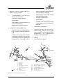
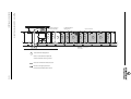
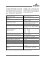
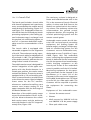
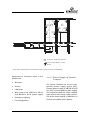
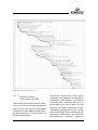
10 Plesetsk Cosmodrome The following is a summary of the detailed information contained in the EUROCKOT handbook EHB0006, Plesetsk User's Manual, which is available upon request. 10.1 General Description The Rockot Plesetsk launch site is located at 62.7° latitude and 40.3° longitude, about 800 km north-east of Moscow and 200 km south of Archangel, Figure 10-1. including 20 launches for Western satellites. Plesetsk Cosmodrome covers an area of 1752 km² and includes Pero Airport (non-civilian) and Railway Station, the town of Mirny, LOX and LN2 plant, ground tracking stations, integration/ technical facilities and launch pads. The main layout of the Cosmodrome is shown in Figure 10-2. Facilities used for the Rockot launch include: Plesetsk Cosmodrome was founded in 1963 as a test range for launchers. Since 1967 several international programs with the participation of France, Germany, Great Britain and the USA have been launched from Plesetsk. By July 2000 Plesetsk Cosmodrome, with a total of 1520 launches, had the highest total in the world (over one third) Figure 10-1: Launch Complex comprising: - Ground support facilities including undertable room, service tower, stationary mast, air conditioning system, fuelling system for stage 1 and stage 2, and equipment for launch preparation - Payload EGSE rooms in the Blockhouse Geographical Location of Plesetsk Cosmodrome ISSUE 3 REV 1 APRIL 2001 10-1 Mission control centre (MCC) in Mirny, which provides: - Accommodation for the Customer during launch - Customer console seating - Countdown - Data display and transmission of launch information - Operational communications Integration facility (MIK) with - General hall for offloading/loading, container cleaning and storage - Clean room bay with upper composite integration room and processing room for spacecraft integration, testing and if 1 9 (safety approval is obtained) for monopropellant fuelling - Administrative area with offices and monitoring room - Fuelling control room - EGSE rooms - Capability for environmentally controlled spacecraft battery storage Helicopter landing pad Fuelling facility for the Breeze upper stage, which can be used upon request (to be agreed with EUROCKOT) for bipropellant fuelling of the spacecraft Airport Hotel Rockot in Mirny 2 N 1 10 11 6 5 4 Road Rail Figure 10-2: 1 2 3 4 5 6 7 8 9 10 11 Tracking Station River Emtsa Railway Head Pero Airport Area 32T Technical Complex MIK Fuelling Facility Area 133 ROCKOT Launch Complex Helicopter Landing Pad Mirny Hotel Rockot Plesetskaya Railway Station 8 35 km 6 km 700 m 100 m 18 km 45 km 20 km 42 km Integration Facility MIK Fuelling Facility Integraton Facility MIK Launch Pad Integration Facility MIK - Helipad Launch Pad Blockhouse Launch Pad Ground Tracking Station Pero Airport Processing Facility MIK Pero Airport Mirny Integration Facility MIK Mirny Plesetsk Cosmodrome Layout ISSUE 3 REV 1 APRIL 2001 10-2 All the facilities used for the Rockot launch are linked by rail and road. The Rockot dedicated launch pad is adjacent and the helicopter landing pad is in the vicinity of the Rockot integration facility MIK, Figure 10-2. 10.1.1 Climatic Conditions The climatic conditions in Plesetsk are continental, with the following characteristics: Minimum winter air temperature: -38°C Maximum summer air temperature: +33°C Maximum precipitation intensity within 12 hours: 0.04 mm/min Average annual precipitation amount: 398 mm June average monthly integral surface density of direct solar radiation flux: 816.6 W/m² Total radiation near the ground surface at 12:30 p.m. without clouds: 844.6 W/m² 10.2 Logistics The main goal of the logistics items described in the following is to provide an overview of how transport, especially of the spacecraft and related equipment, to Plesetsk Cosmodrome can be performed. ISSUE 3 REV 1 APRIL 2001 Related to the geographical location of Plesetsk, the preferred method of entry to Russia is by air. Heavy equipment can be shipped to the international harbours of St. Petersburg and Archangel. The international airports of Moscow, St. Petersburg and Archangel can be considered as possible ports of entry for the spacecraft and related equipment as well as for personnel, since direct international flights to Plesetsk (a limited access area) are prohibited. Considering all logistical and transportation aspects, Moscow and Archangel are the most efficient ports of entry, whereas St. Petersburg can serve as a back-up solution. Table 10.2-1 gives an overview of the characteristics of airports referred to. The basic transport solution for the shipment of the spacecraft and equipment container from the Customer's country to Plesetsk Cosmodrome is via air transport to Archangel (Russian port of entry) and ongoing transport by helicopter to the Cosmodrome as presented in the last paragraph of Section 10.2.1.1. Detailed information concerning all transport items can be taken from the EUROCKOT Handbook EHB006, which can be provided upon request. 10.2.1 Hardware Transport The Customer will be supported by EUROCKOT and KSRC during the customs clearance process at the port-of-entry. As well as entry into Russia, the process of departure from Russia will be assisted by EUROCKOT/KSRC. 10-3 *) Parameters Sheremetyevo Moscow Talagui Archangel Status of airport Runway length Surface solidity, PCN Types of aircraft to be accommodated Landing category Role of airport for S/C shipping International International 3700 m 2500 m 2000 m 3780 m No constraints 44 11 No constraints All types All types All types III II AN-72, AN-12, AN-24, YAK-42, Yak-40 I Port of entry Port of entry Airport to ship S/Cs Port of entry back-up Pero Pulkovo Plesetsk St. Petersburg Launch Base *) Non-civilian International II Pero Airport of Plesetsk Cosmodrome is operated and controlled by the Russian Strategic Missile Forces (RSVN) and can process civilian aircraft only if cleared by the Russian Ministry of Defence (MOD) general staff and possibly subject to special navigator availability on board. Table 10.2-1: Characteristics of Airports for Shipping of Spacecraft Containers and related GSE and Personnel Transfer After entry to Russia, the subsequent transport of the Customers spacecraft and equipment from the Russian port of entry to the Plesetsk launch site and Rockot dedicated facilities is supported and arranged by EUROCKOT/KSRC, as is also the return of the residual hardware to the airport of departure, which will be performed by air and/or rail depending on the hardware volume. Plesetsk Cosmodrome can be reached by rail (Plesetsk Railway Station is located 3 km south of the town of Mirny), by air via Pero Airport, or via the helicopter landing pad near the MIK processing facility. The railway station and the airport are linked to the Rockot dedicated cosmodrome facilities by rail and road, whereas the helicopter landing pad is linked by road. ISSUE 3 REV 1 APRIL 2001 10.2.1.1 Transport Flow by Air For the transfer of the Customers spacecraft and its dedicated equipment from the port of entry to the cosmodrome, two air transport options exist: Delivery of the spacecraft to the Russian port of entry by the Customer, transfer of cargo to a Russian aircraft (e.g. AN-12) and then an onward flight to the Plesetsk Cosmodrome Pero Airport (the aircraft type is restricted, licence necessary, see Table 10.2-1). Ongoing cargo transport to MIK by rail and/or truck. Delivery of the spacecraft to the Russian port of entry Archangel by the Customer (AN-124 or IL76), transfer of cargo to a Russian helicopter 10-4 (MI-26T) and then a flight to the Plesetsk Cosmodrome helicopter landing pad at a distance of 700 m from MIK. Incoming cargo will be transported by truck to MIK. 10.2.1.2 Temperature and humidity conditions during transport Maximum allowable duration for interruption of container power supply and maximum/minimum allowable ambient temperatures during periods of cargo transhipment Allowed ground transport speeds and dynamic loads, as well as offloading and loading equipment for transportation at the launch site Transport Flow by Rail The transfer of the Customers satellites and related equipment from the different ports of entry (e.g. the international harbours in Archangel and St. Petersburg) or the international airports of Moscow, Archangel and St. Petersburg to Plesetsk Cosmodrome can generally be performed by rail. The disadvantage of this transportation method is the dependency on the public railway system, with the result that the required transportation speeds cannot be guaranteed. 10.2.2 Transport Requirements The transport requirements for spacecraft and related equipment must be described in detail in the Spacecraft Operations Plan (SOP) and must cover the following at least: Container handling and storage requirements Number, dimensions, weight, centre of mass, and material of all containers Container grounding requirements Necessity of immediate container transfer or possibility of intermediate storage upon arrival Container power supply ISSUE 3 REV 1 APRIL 2001 10.2.3 Transport Environments The spacecraft and its equipment will be subjected to mechanical and thermal environments during their transportation by air and on the ground, as well as during ground handling. In Section 5 of the EUROCKOT User's Guide, dealing with Spacecraft Environmental Conditions, the worst case transportation and handling loads are described, as well as the thermal environment during transport. Additionally, the results of transportation load measurements for rail, road, air and helicopter transport are included. 10.2.3.1 Environmentally Controlled Transport of Spacecraft during Launch Campaign For the transport of spacecraft as part of the upper composite from MIK to the launch pad, a mobile air conditioning system is available, Figures 1-20 and 1-21. 10-5 In order to maintain the required temperature-moisture conditions and cleanliness under the head fairing in the vicinity of the spacecraft, the thermal conditioning unit is connected to the space nose cone after its assembly and reloading on the transportation unit. Thermal conditioning in a closed circuit is performed during transportation of the upper composite to the launch complex: air supply under the head fairing, air escape through the upper stage intermediate compartment. During transportation, the air temperature under the nose fairing and the spacecraft adapters is controlled with the aid of the ground measurement system. The characteristics of supplied air can be taken from Chapter 5.2.3. More detailed information on the mobile air conditioning is provided in the EUROCKOT handbook EHB0006, Plesetsk Cosmodrome User's Manual, which can be provided upon request. 10.2.4 Spacecraft Team Transport to Plesetsk Cosmodrome Customer personnel transfer from the Russian port of entry to Plesetsk Cosmodrome, as well as the transfer from hotel to Launch Site facilities, will be arranged and supported by EUROCKOT/ KSRC. During all transfer phases within Russia, the Customers personnel will be accompanied by EUROCKOT/KSRC personnel. Upon request, quotes for aircraft/rail transportation fees will be provided. ISSUE 3 REV 1 APRIL 2001 For entry to Russia, EUROCKOT/ KSRC will support the Customers team in all necessary formalities for customs clearance and in the obtaining of visas for the spacecraft team. As well as entry to Russia, departure from Russia will be also be assisted by EUROCKOT/KSRC. Normally the spacecraft team will arrive at Sheremetyevo International Airport, Moscow. The ongoing possibilities of transfer to Plesetsk Cosmodrome are described in the following. 10.2.4.1 Charter Aircraft Pero Airport at Plesetsk has limitations on the aircraft to be accepted, Table 10.2-1. For the transport of the Customers personnel, a YAK-40, Figure 1-22, will normally be used. This aircraft can be provided in an economy class configuration with 22 seats or in a configuration with 5 business class seats and 10 seats of economy class. The flight duration from Moscow to Plesetsk is 1.5 hours. For convenience, the Customers personnel will be transported by charter flight from the Russian port of entry to Pero Airport at Plesetsk during a launch campaign. 10.2.4.2 Scheduled Flights The nearest airport to Plesetsk Cosmodrome for scheduled flights is the airport in Archangel. The flight route Moscow-Archangel-Moscow (flight duration approximately 1.45 hours) is a regular schedule operated by Archangel Airways and Aeroflot. 10-6 10.2.4.3 Rail Transfer to Plesetsk Cosmodrome Another option for travelling to Plesetsk is by rail. For rail transfer from Moscow to Plesetsk (3 km south of Mirny), 18 hours can be assumed, whereas rail transfer from Archangel to Plesetsk will take approximately 5 hours. The subsequent transfer to Hotel Rockot in Mirny, which is located in military territory, will be organised by EUROCKOT. Transfer to the national airport or railway station in Moscow will be arranged and accompanied by EUROCKOT/KSRC, as will also the transfer to Plesetsk Cosmodrome. 10.2.4.4 Transfer by Car or Bus from Archangel to Plesetsk Cosmodrome If the Customers personnel arrive in Archangel, transfer to Plesetsk Cosmodrome can also be performed by car or bus, arranged by EUROCKOT/KSRC. The transfer time in that case will be approximately 4.5 hours. For the convenience of the Customer, EUROCKOT has an arrangement with a business hotel in Archangel if overnight stays in Archangel are required. 10.2.5 Customer Team Transport at the Launch Site At the launch site, buses, minivans and, if necessary, trucks will be made available to transport the management team, technical and support personnel and security guards to the work area ISSUE 3 REV 1 APRIL 2001 during spacecraft processing and launch operations according to the daily working schedule. The distance between Hotel Rockot where the Customer is accommodated and the technical complex is 42 km; the average transfer time by bus is approximately one hour. 10.3 Communications Reliable and independent national and international communication facilities are provided by the telecommunication system installed in Plesetsk. The following types of telecommunication services are available: Local and international direct dial (IDD) phone lines Data lines LAN Mobile radios (IDD) CCTV Various types of telecommunications support at the Mission Control Centre (please refer to Section 10.4.4) Entertainment TV in the hotel 10.3.1 Phone Lines The national and international phone lines support links between launch site facilities, the Mission Control Centre and the hotel. Multi-purpose RJ 45 jacks are used to connect either ISDN or analogue phones. Access to mobile radios is possible within the phone network. 10-7 10.3.2 Data Lines In order to support data transmission at the launch site, inter-area data lines connecting the integration facility MIK, the launch complex and the hotel, as well as international data lines, are available. The launch site inter-area data lines comprise: Analogue interface for modembased transmissions at up to 19.2 Kbps ISDN interfaces for data rates of up to 128 Kbps V.35 interfaces for data rates of up to 64 Kbps E1 data interface to support a 2048 Kbps broadband data link between the processing facility, the bunker and the Rockot hotel Data transmission over a multimode fibre optic cable between the undertable room and the integration facility ports either conference sessions or point-to-point links, with mobile radio access to or from the launch-base phone network being possible. The required quantity of calling groups will be preprogrammed in each portable radio in use by the Customer. 10.3.4 Security video monitoring services will be provided at the integration facility and the launch complex. The system enables monitoring of the spacecraft and the Customers GSE with the image sent to the Customers rooms, taped and/or played back. The following video support is available at the launch site: Explosion-proof video cameras available in all clean rooms with the camera outputs delivered to the Customers office Video monitors available in the Customers office. Each video camera can be remotely controlled (i.e. panned, tilted, focused and/or zoomed) from this office Video taping capabilities Video cameras available in the undertable room to monitor the Customers GSE. The outputs from these cameras will be sent to the Customers room in the blockhouse as well as to the Customer offices at the integration facility Video monitors available in the Customers rooms within the blockhouse LAN in MIK, bunker and Hotel Rockot with RJ45 interface 10.3.3 Mobile Radios In Plesetsk,there is a mobile radio system built around UNIDEN ESAS hardware. Mobile radio links will be available at the integration facility MIK, at the launch site, in the Customer accommodation area and also along the routes interconnecting any two of these locations. The mobile radio system sup- ISSUE 3 REV 1 APRIL 2001 CCTV 10-8 10.3.5 Entertainment TV Four different TV channels in English, German and/or other languages upon request are available in each hotel room used by the Customers staff. 10.4 Ground Facilities A detailed description of the EUROCKOT dedicated technical facilities at the launch site, their equipment and specifications can be taken from the EUROCKOT handbook EHB0006, Plesetsk Cosmodrome User's Manual, which can be provided upon request. 10.4.1 Areas Intended for Sole Customer Use At the launch site, the areas listed below and described later in detail are intended (upon request) for sole Customer use and therefore under his security control. For these areas, the Customer can implement access control procedures in accordance with Customer state governmental regulations. Within the integration facility MIK, the Customer has its closed dedicated area under its sole security control. Within this dedicated area the Customer can move without escort. This closed dedicated area contains: A spacecraft processing area for conducting autonomous spacecraft operations and spacecraft fuelling EGSE rooms for support equipment installation ISSUE 3 REV 1 APRIL 2001 Change rooms, shower and rest rooms as well as an air shower Emergency exits with emergency showers and eye wash facility Office area Access to the Customer area on the first and second floor of MIK can be gained via a separate entrance with staircase or escorted via the general MIK entrance. An additional staircase in the Customer's office area allows direct access to the foyer of the Customer's changing rooms. Entrance to the spacecraft processing area and EGSE rooms, as well as to the upper composite integration area in the case of joint operations, is possible without contact with Russian controlled areas. At the launch complex, the following areas are dedicated to the Customer: Undertable Room Mission Control Room in the blockhouse Video observation of the clean room area as well as the undertable room (also under Customer security control) can be performed from the Customers security office. During launch, a separate Mission Control Centre is available. 10.4.2 The Integration Facility MIK The integration facility MIK (the internal designation is building 130 in area 32T), Figure 1-23, is located in the south-east area of Plesetsk Cosmodrome at a distance of 6 km from the EUROCKOT 10-9 launch complex and 42 km away from the town of Mirny, where the Customers personnel will be accommodated. The spacecraft container and related equipment can be directly delivered to MIK by helicopter. A helicopter landing pad is located in the vicinity of MIK. The integration facility MIK (its ground floor plan is shown in Figure 10-3) is intended for acceptance, storage, assembly and checking of boosters, Breeze and fairing, acceptance of spacecraft, spacecraft operations and assembly of the upper composite, and comprises: General hall with common work area Clean room bay, certified cleanliness class 100,000 (Customers requiring clean room cleanliness conditions better than the standard class 100,000 should contact EUROCKOT for further information) with - hardware air-lock (54 m²) and personnel air-lock - clean room for upper composite encapsulation (146 m²) - clean room for spacecraft processing and fuelling (180 m²) ISSUE 3 REV 1 APRIL 2001 Two EGSE rooms with capability for cooled battery storage Administrative area with Customer offices and rooms for remote control If the fuelling procedures fulfil the Plesetsk safety requirements, spacecraft will be fuelled within MIK. In that case one of the EGSE rooms can be used as a fuelling control room. Fuelling of spacecraft with cold gas systems or monopropellant will take place on a fuelling platform within the closed clean area described above. For fuelling with bipropellant, a separate fuelling facility can also be made available. If requested, EUROCKOT can optionally provide a fuelling service performed by an experienced and qualified team. The clean room bay is equipped with an oxygen content control system and a hydrazine monitoring system. Critical values will automatically initiate alarm by acoustic and visual means. Fire protection in the integration facility is provided not only in the usual way but also by a water deluge system on the walls and by water curtains on the doors of the clean room bay. 10-10 Figure 10-3: Layout of Integration Facility MIK 3,5x3,5m E F Side Entrance 4 WC 2,5x2,5m 5x11m A 2,1x2,1m 4x6,5m B C 9 D 8m 5x11m 9,4m ISSUE 3 REV 1 APRIL 2001 Emergency Exit 10 Main Entrance 1 2 7 6m 5 15m 8 9m 19,4m 30m Main Hardware Door 5 Emergency Exit 6 A B C D E F 3 General Hall with Common Work Area Hardware Airlock Upper Composite Integration Area S/C Processing Area EGSE Room EGSE Room 10-11 1 2 3 4 5 6 7 8 9 10 Mobile Integration Table for Upper Composite Integration S/C Container S/C Container on Railway Car Refrigerating Container MOTEK Travelling Cranes Upper Composite Integration and S/C Processing Area Travelling Crane General Hall Travelling Crane Airlock Fuelling Platform Viewing Window Transition 2nd Floor Air Shower Emergency Shower 10.4.2.1 General Hall The common work area with 500 m² in the general hall of MIK is dedicated for ground support equipment unloading, unpacking/ packing and short-time storage,. booster preparation, autonomous checks of Breeze and fairing, and electrical checks of the assembled upper composite. For overhead crane operations, an overhead travelling crane with 30 tons lifting capacity (for crane specification and dimensions of crane hook please refer to EUROCKOT handbook EHB0006) is installed. The general hall is not environmentally controlled. 10.4.2.2 Clean Room Bay Satellite processing as well as upper composite integration and encapsulation will take place in the closed clean area of MIK, Figure 1-24, which is certified to cleanliness class 100,000 as per FED-STD209A. The particular parameters of environmental control can be taken from Section 5.2.2. 10.4.2.2.1 Airlock The airlock located at the beginning of the clean room bay has a base area of 54 m² (9.4 m wide and 6 m long). An overview of the equipment of the airlock is given below. Final cleaning of the spacecraft container and associated equipment will be done here. ISSUE 3 REV 1 APRIL 2001 Equipment of the airlock: Explosion-proof cameras for remote control Explosion-proof phones Wall mounts for 208/120 V 60 Hz and 380/220 V 50 Hz power supply 2 t overhead crane Sensors, acoustic and visual warning devices of oxygen control system Sensors, acoustic and visual warning devices of hydrazine control system Particle counter Grounding terminals Emergency lighting Fire protection system Entrance door size of airlock 5 m (width) x 11 m (height) 10.4.2.2.2 Upper Composite Integration Area The upper composite integration area covers an area of 146 m² and is located between the airlock and the spacecraft processing area. The upper composite integration area is intended for the mating of the spacecraft with Breeze and assembling of the upper composite. The equipment of the upper composite integration area is stated below. The upper composite integration area is accessible for the Customers personnel from the clean room changing area under the Customer's security control after they have passed through the air shower. 10-12 Equipment of the upper composite integration area: Explosion-proof cameras for remote control Explosion-proof phones LAN-drops Wall mounts for 208/120 V 60 Hz and 380/220 V 50 Hz power supply 10 t overhead crane Emergency exit with emergency shower and eye wash facility Sensors, acoustic and visual warning devices of oxygen control system Sensors, acoustic and visual warning devices of hydrazine control system Particle counter Grounding terminals Emergency lighting Fire protection system Entrance door size of upper composite integration area 5 m (width) x 11 m (height) 10.4.2.2.3 Spacecraft Processing Area The spacecraft processing area, placed under Customer security control, covers a total area of 180 m². This area of the clean room bay is intended for spacecraft processing, and comprises a 90 m² work area and a spacecraft fuelling area with 90m². The spacecraft processing area is accessible for the Customers personnel through a separate entrance from the clean room changing area ISSUE 3 REV 1 APRIL 2001 under the Customer's security control after they have passed through the air shower. Two emergency exit units for fuel leakage neutralisation are installed, each comprising two showers and one eyewash facility, in the north and the east, respectively, of the processing area. All operations in this spacecraft processing area can be monitored and recorded; an explosionproofed window providing a view from EGSE room 2, which can be used as a fuelling control room, also provides observation of the processes (please refer to the paragraph dealing with EGSE rooms). For spacecraft fuelling operations, KSRC can provide a removable fuelling platform, Figure 10-4 and Figure 1-25, which will be located in the spacecraft processing area, Figure 10-3. The fuelling platform provides support and containment in the event of a spill. The provision of compressed air and technical water to wash out spillage is a standard service of KSRC. Equipment of the spacecraft processing area: Explosion-proof cameras for remote control Explosion-proof phones LAN-drops Wall mounts for 208/120 V 60 Hz and 380/220 V 50 Hz power supply 10 t overhead crane Removable fuelling platform Emergency exit with emergency shower and eye wash facility 10-13 Sensors, acoustic and visual warning devices of hydrazine control system Particle counter Grounding terminals Emergency lighting Fire protection system Entrance door size of spacecraft processing area 4 m (width) x 6.5 m (height) Figure 10-4: Scheme of Removable Fuelling Platform 10.4.2.3 EGSE Rooms Adjacent to the clean area, two EGSE rooms are provided, which are not environmentally controlled They can be used for accommodation of the electrical equipment, to tool up workshops to support spacecraft processing, and/or in addition for temperature-controlled battery storage and battery processing. If battery cooling is required, a battery cool cabin called MOTEK, will be provided. The total area of the EGSE rooms its 100 m². The rooms, EGSE room 1 with 60 m² and EGSE room 2 with 40 m², are divided by a fence with a sliding gate. EGSE room 2 is equipped with an explosion-proof window to observe the oper- ISSUE 3 REV 1 APRIL 2001 ations in the spacecraft processing area. If fuelling of the spacecraft is performed in the spacecraft processing area, EGSE room 2 can be used as a fuelling control rooms. Equipment of EGSE rooms: Cameras for remote control Monitors (optional) Phones LAN-drops Wall mounts for 208/120 V 60 Hz and 380/220 V 50 Hz power supply Emergency lighting Common fire protection system Size of entrance door size to EGSE area from spacecraft processing area 2.1 m x 2.1 m 10-14 10.4.2.4 Customer's Office Area The Customers offices are located on the 2nd floor of the integration facility extension in the vicinity of EUROCKOT and KSRC offices. This 2nd floor is above the EGSE rooms and clean room changing area. Access to the Customers office area is provided via the common MIK entrance or by a separate staircase. The entrances to the Customers office area corridor are secured by lockable doors. The administrative area for the Customer comprises seven offices ( 4 x 41 m² and 3 x 20 m²) dedicated to sole Customer use, Figure 10-5. All rooms are equipped with heating, smoke detectors and fire extinguishing systems and have a telephone/fax capability, LANdrops and a 60 Hz and 50 Hz power supply. Room 210 of the Customers office area provides direct access by stairs to the changing rooms of the clean area. Room 209 provides video monitoring capabilities for the TV cameras which are installed in the processing area. Room 213 is equipped to monitor spacecraft data and conduct spacecraft battery charging activities while the spacecraft is on the launch vehicle prior to launch. For that purpose, the spacecraft remote control equipment to be placed in room 213 can be connected to the spacecraft EGSE to be placed in the undertable room via a full duplex fibre optic cable. Office equipment such as fax devices, electronic data processing system and computer monitors, copy machines, overhead projectors etc. is available upon request. ISSUE 3 REV 1 APRIL 2001 10.4.2.5 Handling and Hoisting Equipment in MIK A detailed description of all handling and hoisting equipment available in MIK is part of the EUROCKOT handbook EHB0006 Plesetsk Cosmodrome User's Manual which can be provided upon request. The main handling and hoisting equipment in MIK comprises: Boom lift (cherry picker) Fork lift Rail car Trolley for adapter with spacecraft Mobile integration table Upper composite assembly stand 10.4.2.6 Power Supply of MIK Uninterrupted power is supplied in all Customer dedicated areas in MIK, airlock and upper composite integration hall with 208/120 V at 60 Hz. The installed sockets are of the Hubbell type with circular flange. Other connectors as well as a power supply of 380/220 V at 50 Hz is available upon request. The 208/120 V, 60 Hz power supply system (PSS) is a self-contained power supply system set incorporating two dieselgenerators and two uninterrupteible power sources (UPS). The PSS rated power output is 100 kW. The PSS specifications are listed in Table 10.4-1. 10-15 Figure 10-5: Customer Office Area in MIK ISSUE 3 REV 1 APRIL 2001 Mission Management/ Briefing Office KSRC 1st floor 207 female 206 208 EUROCKOT Mission Management 209a 209 210 Customer Offices 210a 211 212 213 214 male 1st floor Transition to room 110 of 1st floor 109e Internal Room Designation Office rooms 209 to 214 placed under Customer security control Area for movement without escort Route for foreign specialists movements under Russian escort 10-16 The power supply system can operate non-stop for 30 days before it is turned off for maintenance work. In the case of failure of either a diesel generator (DG) or an uninterruptible power source (UPS), the other DG or UPS will run at rated 100 % power output. The uninterruptible power source includes builtin battery-supported static voltage converters providing a rated 100 kW load for not less than 10 min. Rated power output 100 kW ( cos j = 0.8 - 1 ) Power change under load (power consumers) from 0 to 100% of the rated output Line output voltage 208 V and three-phase current with a frequency of 60Hz Phase output voltage 120 V and single-phase current with the rated frequency of 60 Hz Voltage and current waveform smooth sine curve Stable output voltage variation ±1%, continuous with the load increasing from 0 to 100% and falling back to 0 Overload capacity at 110% £ 20 min power output of 125% £ 10 min 150% £ 1 min 200% £ 1 sec Stable output frequency deviation ± 1%, continuous Total harmonic distortion factor < 3% in static conditions < 5% in dynamic conditions Storage battery capacity not less than 10 min Voltage regulator response time < 5 msec Radio interference level below "N" as per VDE 0875 Efficiency at rated load > 90% Protection to DIN 40050 Standard 1P21 Duration of system operation continuous and uninterrupted for up to 30 days Type of system of current-carrying conductors three-phase, five-wire (A,B,C - phases, N - neutral wire, PE - earth wire) Table 10.4-1: Specification of 208/120 V 60 Hz AC Processing Facility Power Supply System ISSUE 3 REV 1 APRIL 2001 10-17 10.4.3 The Rockot Launch Complex The Launch Complex as shown in Figure 10-6 is dedicated to Rockot launches exclusively for use by EUROCKOT. In the course of rebuilding and renovating work for all Rockot dedicated facilities in the years 1999/2000, the Rockot Launch Complex underwent a complete renewal, so that today all equipment is state-of-the-art. The Rockot Launch Complex is situated in the north-east area of Plesetsk Cosmodrome, at a distance of 6 km from the MIK Processing Facility. The Rockot launch pad with undertable rooms is approximately 100 m west of the blockhouse. The railroad terminates directly in front of the launch table for loading and unloading the booster stages and upper composite. The blockhouse is located between the underground propellant and oxidiser storage tanks for booster fuelling. The distance between oxidiser and propellant storage tanks is 80 m. The underground storage tanks and the blockhouse are situated on a north-south axis. A site plan of the Rockot Launch Complex is shown in Figure 10-6. N Railroad Transformer Neutralisation Station Fuel Storage Waste Deposit Road Lightning Protection Blockhouse Channels Service Tower Supply Control Station (Utility Room) Water Storage Rail System Oxidiser Storage Not to scale Figure 10-6: The Launch Complex for Rockot ISSUE 3 REV 1 APRIL 2001 10-18 10.4.3.1 Launch Pad The launch pad includes a launch table with launch equipment and a stationary mast, surrounded by the mobile service tower during LV processing, Figure 10-7 and Figure 1-13. Undertable rooms contain the LV electrical GSE and pre-launch processing equipment, the fuelling system for booster stage 1 and stage 2 and the payload air conditioning system, as well as a Customer-dedicated undertable room for accommodation of the EGSE. The launch table is equipped with retractable supports for the alignment of the LV. The maximum turning capacity of the launch table for adjustment of the azimuth is 180°. The gas deflectors of the pad are metallic, whereas the covering surface is made of concrete. The mobile service tower is designed for vertical integration of the upper composite with the Rockot booster. In a closed gate position, the service tower encloses the Rockot. The service tower is equipped with a lift and working platforms at several levels to provide access to the LV service areas. A special adapter frame serves for the TLC erection, whereas an overhead travelling crane ensures zero impact mating of the upper composite with the 2nd stage of the Rockot booster unit. Retraction of the mobile service tower occurs 10 minutes before lift-off. At liftoff, the distance between the rolledback service tower and the stationary mast with Rockot in the TLC is approximately 50 m, Figure 1-26. ISSUE 3 REV 1 APRIL 2001 The stationary column is designed to fasten and hold the booster unit in the TLC at the moment of launch. Electrical cables, air ducts and fluid lines to the Rockot are maintained via the stationary column. The stationary column also accommodates the ground control equipment devices, the targeting (LV azimuth positioning) system and the remote control system. Undertable rooms contain the LV electrical GSE and pre-launch processing equipment, the fuelling system for booster stage 1 and stage 2 and the payload air conditioning system. For the Customer's use one undertable room, designated as room 7 with 29 m², is provided, Figure 10-8. This undertable room, containing the equipment stated below, is dedicated for the accommodation for the spacecraft on-board battery trickle charging equipment at the launch pad. Access to the undertable rooms is possible until the LV is fuelled. Monitoring equipment for the spacecraft parameters can be situated in the blockhouse or in room 213 of the Customers office area in the integration facility MIK. Undertable room 7 is linked to room 213 via a fibre optic cable. The Customer will be required to provide the equipment for connecting the fibres. Equipment of the undertable room: Camera for remote control Phones Wall mounts for 208/120 V 60 Hz and 380/220 V 50 Hz power supply Fibre optic cable access 10-19 Service Tower Crane, G= up to 12,5 tons Upper Composite Transport Container Upper Part Guidance Compartment Compartment for On-ground Control System Booster Stages 1 & 2 in Launch Container Statonary Mast Mobile Air Conditioning System Attachment Frame Launch Table Figure 10-7: Launch Pad ISSUE 3 REV 1 APRIL 2001 10-20 P5 P6 7 P4 4,2 7,25 Launch Table above Cam2 P7 7 Room Number Camera Area for movement without escort Route for foreign specialists movement under russian escort 4 Dimensions in metre Roomhight: 2,3 m Fiber Optic Connector Phone Figure 10-8: Undertable Room for the Customers Use 10.4.3.2 Blockhouse The blockhouse, which can also be used as a mission control room and for monitoring of spacecraft parameters, is located approximately 100 m east of the launch pad. The blockhouse, designed to Russian standards, has a shock wave resistance capacity of 2 kg/cm2 and incorporates a self-contained life-support system Two individual rooms with areas of 36 m² and 28 m² respectively, Figure 10-9 ,will be provided for the Customer, for console seating during satellite checkout and battery charging (also available in the office area of the MIK) and for accommodation of the spacecraft ISSUE 3 REV 1 APRIL 2001 EGSE,which is not placed in the undertable rooms. Control consoles for booster fuelling and for the supply of the conditioned air and/or gas to the launch vehicle container and to the fairing are located at the upper level of the blockhouse. There are stationary harnesses routed in an underground channel to the undertable room, from which the umbilical is connected to the launch vehicle and spacecraft EGSE. The cable length from the blockhouse to the launch pad is less than 100 m. 10-21 P13 P12 L3 P19 P18 L6 5 4 P11 P10 L2 9,5 P17 P16 L5 P9 P8 L1 P20 P21 L7 4 P22 P23 L8 P15 P14 L4 4 4 Internal Room Designation Local Area Network (LAN) Phone Figure 10-9: Customer Rooms in the Blockhouse with Location of Phones and LAN-Drops Equipment of Customer rooms in the blockhouse: Monitors Phones LAN-drops Wall mounts for 208/120 V 60 Hz and 380/220 V 50 Hz power supply Emergency lighting Fire extinguishers ISSUE 3 REV 1 APRIL 2001 10.4.3.3 Power Supply of Launch Complex The Launch Complex has its own independent power supply system (PSS). General power supply is 208/120 V at 60 Hz, with uninterruptible power supply. The installed sockets are of the Hubbell type with circular flange. Other connectors and a power supply of 380/220 V at 50 Hz are available upon request. 10-22 The Launch Complex power supply system (PSS), which incorporates two diesel-generators and two uninterruptible power sources (UPS) with a power output of 100 kW, is identical to that of the MIK processing Facility; for the specification, please refer to Section 10.4.2.6. 10.4.3.4 Air Conditioning of the Spacecraft and Spacecraft Batteries at the Launch Pad After encapsulation, air conditioning of the payload is provided during transportation of the upper composite to the pad and up to 5 minutes before lift-off. Depending on the fairing design, purging of the spacecraft batteries can also be performed if required. Interruption of the payload air conditioning occurs only for periods of no longer than 1 hour each. At the launch pad, the stationary air conditioning equipment is located under the launch table and the air duct passes through the stationary mast. The air duct and the air inlet of the fairing are connected via a flexible tube. Before entering the flexible tube, the air guided by the air duct passes through a filter and past a flap. The payload (and battery) air conditioning system will be switched off 5 minutes before lift-off contact. The air conditioning lines will only be disconnected during lift-off, so that in the case of a launch cancellation the air conditioning system will be switched on within £ 5 minutes The air conditioning system for the ISSUE 3 REV 1 APRIL 2001 spacecraft and spacecraft batteries is compatible with class 100,000 cleanliness and has the characteristics described in Chapter 5, where the general scheme of the open circuit air conditioning system is also shown. EUROCKOT/KSRC will provide periodic monitoring (the minimum interval is 15 minutes) of air temperature and humidity and air flow of fairing air and battery air during the time the spacecraft is on the launch pad. 10.4.4 The Mission Control Centre The Mission Control Centre is located in the town of Mirny at a distance of approximately 40 km from the launch pad. The MCC will provide: Local, interurban and international telephone communications with the capability of telephone conferencing Video and audio reporting from the launch site in real time Countdown Transmission and receive of the formats in electronic and fax form Operational communications with launch support services Display and transmission of launch information in real time The following data can be displayed on large-size wall panels: CG motions for stages 1 to 3 and the fairing during powered flight in the ascent plane; ranging data; key flight events (such as staging and 10-23 jettisoning of the fairing); major telemetry data down link and tipoff angles. Sub-orbital unit track on an earth map accompanied by the display of ranging data, key flight events (such as Breeze burns), major telemetry data down link timelines for ground telemetry stations, and predicted or actual orbit parameters Computer-generated presentation of spacecraft motion about its CG, with the viewing angle and solar exposure. In this mode, staging events are displayed and several Breeze performance quantities are presented in numerical form 3D motion of the item's CG against the earth background and several orbit parameters in numerical form Generalised state vector including geodetic position, predicted as well as actual orbit parameters, and the predicted as well as telemetered Breeze engine performance Live launch coverage The Mission Control Centre is equipped with hardware and software which allows integration of any other information (which may come from foreign monitoring facilities during and/or after spacecraft injection) into the set of data displayed. In addition, processed flight data can be compressed and sent to any remote user to be decompressed and displayed. ISSUE 3 REV 1 APRIL 2001 10.5 Launch Campaign 10.5.1 Responsibilities and Operational Organisation EUROCKOT/KSRC is responsible for the preparation of the launch vehicle and combined operations. The Russian Strategic Missile Forces (RSVN) execute Rockot operations including launch as subcontractors to EUROCKOT/KSRC. EUROCKOT/KSRC will provide support for the installation of the Customers spacecraft on the launch adapter. Additional support has to be mutually agreed between EUROCKOT/KSRC and the Customer. Spacecraft preparation will be performed under the responsibility of the Customer and its launch site team. During the launch campaign, a core of the EUROCKOT team responsible for the specific Customer mission will be present at the range as day-to-day intermediaries between Customer, KSRC and range authority and to coordinate the spacecraft launch site support requirements as well to accompany the Customers launch site team in all personnel matters. The EUROCKOT team is supported by a KSRC team at the range. Both teams ensure undisturbed execution of all necessary operations until launch and the fulfilment of spacecraft support requirements in accordance with the launch site requirements. 10-24 10.5.2 Planning Spacecraft launch site operations and the relevant requirements will be specified in a Spacecraft Operations Plan (SOP), that should be available as early as possible. This document should address all operational and logistical support requirements. All spacecraft activities and technical facilities will be controlled at the launch site according to the Launch Operation Schedule (LOS) and Combined Operation Plan (COP). The Launch Operations Schedule (LOS) gives an overview of the spacecraft operations and joint operations to be conducted at the launch site, and defines ground rules for all involved parties at the range. The LOS has been established to define for both operations the equipment and support needed at the launch site in order to ensure undisturbed working conditions for the Customer. Due to the parallel processing of spacecraft and launcher up to the joint operations prior to launch, these activities have to be coordinated to ensure the availability of neccessary equipment and support personnel and the accessibility of facilities, taking into account the security and safety matters of all parties involved. During the launch campaign, a daily schedule meeting will be held with the participation of all parties involved, Customer, EUROCKOT/KSRC and attendees from RSVN. The goal of this meeting is to: Communicate the status of the work ISSUE 3 REV 1 APRIL 2001 Identify issues that require immediate attention Define the schedule and coordinate operations for the next day with a view to the support personnel needed, access to facilities, transportation needs, lunch times. Coordinate future joint operations Adapt the launch campaign schedule if necessary 10.5.3 Procedures and Logbook of Works Every process will have an approved procedure. These procedures will identify in detail the necessary equipment, personnel, documentation and facility requirements to complete the process. The related launch site procedures will be carried out under consideration of safety and security regulations of the Russian Government and the Customer State Government. All procedures for joint operations have to be signed off by the Customer and KSRC/EUROCKOT. Joint operations will be documented in a logbook. The joint working steps are in Russian and English and have to be signed off by all parties after completion of the work. 10.5.4 Training / Briefings Training and briefings for the spacecraft operations team will be performed before the start of the spacecraft operations. Such training and briefings comprise: 10-25 Familiarisation with emergency evacuation procedures and all alarms Communications equipment operations Security requirements and briefings Training to operate launch site specific equipment 10.5.5 Security and Access Control The security requirements for Plesetsk will be defined in the Joint Launch Site Security Plan. This document considers the requirements from the Russian side as well as the requirements of the Customer State Government. 10.5.6 Safety The safety regulations - see also Chapter 9 - define the rules applicable to all operations and the constraints to be observed in the definition and performance of launch vehicle and spacecraft operations. 10.5.7 Launch Campaign Operations The launch campaign operations, especially the spacecraft operations described in the following, serve the purposes of orientation. For a programme, the duration of a launch campaign will be tailored to the Customers requirements. A final and detailed Launch Operations Schedule (LOS), which includes a statement of the ISSUE 3 REV 1 APRIL 2001 precise duration of all operations, will be established after definition of the COP (Combined Operations Plan) together with the Customer. A typical Customer launch campaign from arrival of the spacecraft and related equipment at the Cosmodrome until launch will last approximately 19 days. The time needed for post-launch activities (up to three days) has to be added. A complete launch campaign, which also takes the LV operations into account, consists of three major parts: Launch vehicle operations in MIK, duration 16 to 17 days Spacecraft operations, duration depending on Customer needs, average duration 9 to 10 days Joint operations, duration 10 to 11 days The spacecraft will arrive on day L-19, whereas the spacecraft operation team will usually arrive earlier to prepare for the delivery of the spacecraft container and equipment at the Russian port of entry and the ongoing transport to the launch site. The combined operations start on day L-11. The launch vehicle processing is performed in parallel with the space vehicle processing. The major launch vehicle processing, spacecraft operations and combined launch vehicle / spacecraft tasks are summarised in the operations schedule, Figure 10-10. 10-26 Figure 10-10: Schedule of Operations 10.5.7.1 Launch Vehicle Operations in MIK The stand-alone launch vehicle operations at the launch site typically start on day L-27 with the arrival of the Rockot components at the MIK processing facility and end on day L-11 with the start of combined operations. ISSUE 3 REV 1 APRIL 2001 Before the components of the upper composite are prepared for spacecraft integration and assembly, an electrical Breeze/booster interface check-out is performed at the launch pad. For this purpose, the upper composite will be assembled, transported to the launch pad and stacked on the second stage. All operations dedicated to the electrical Breeze/booster interface check-out 10-27 activities, are similar to the launch operations, but do not include the fuelling of the Breeze and are performed without the spacecraft. The main launch vehicle stand-alone operations up to the beginning of the combined operations are shown in Table 10.5-1. Launch Vehicle Operations in MIK Day L-27 Arrival of Rockot components (booster Unit, Breeze, fairing and TLC extension) in Plesetsk, unloading, incoming inspection and transfer to general hall of MIK Transfer ring and thermal cover installation on Booster Unit L-26 Fairing accommodation on mobile integration table, transfer to clean room and disassembly into fairing halves Breeze transfer into clean room and accommodation on mobile integration table Booster unit transport to the launch complex L-25 Vertical assembly of upper composite Upper composite transfer to general hall of MIK L-24 Upper composite electrical checks Transport of TLC extension to launch pad L-23 Installation of docking device and thermal cover on upper composite Transfer and accommodation of upper composite to transport unit of mobile air conditioning unit Connection of upper composite to mobile air conditioning unit and ground and vibration measurement system Thermally conditioned transfer of upper composite to launch pad in vertical position L-22 to L-19 LV operations at launch pad (Breeze/booster electrical interface check-out) L-19 Thermally conditioned transport of upper composite from launch pad to MIK L-18 Transfer and accommodation of upper composite to mobile integration table Removal of thermal cover and docking device Upper composite transfer to integration area of clean room bay and disassembly L-17 Commission for release of Breeze fuelling L-16 Breeze removal from mobile integration table, transfer to dolly and roll-out to general hall L-15 Breeze accommodation on transport unit of mobile air conditioning unit and transport to fuelling station Start of Breeze fuelling L-14 to L13 Fuelling of Breeze L-12 Breeze transport to MIK L-11 Incoming inspection and acceptance of fuelled Breeze Breeze offloading and loading onto dolly, Breeze transfer to clean room for upper composite Integration and installation of Breeze on mobile integration table START OF COMBINED OPERATIONS Table 10.5-1: Launch Vehicle Operations in MIK ISSUE 3 REV 1 APRIL 2001 10-28 10.5.7.2 Spacecraft Operations The spacecraft operations at the launch site nominally start on day L-19 with the arrival of the spacecraft and spacecraft GSE container. The spacecraft autonomous operations are conducted in the spacecraft processDay ing area of the clean room bay of MIK. An example of autonomous spacecraft and spacecraft-related operations aisshown in Table 10.5-2. An additional two days for the spacecraft operations are necessary if spacecraft fuelling is performed in the bipropellant fuelling facility instead of MIK. Spacecraft Operations L-20 Spacecraft and spacecraft GSE container unloading at port of entry, customs clearance and transfer to Plesetsk L-19 Arrival of spacecraft and related GSE container at Plesetsk Cosmodrome Spacecraft container offloading, loading onto truck(s) and transport to MIK Offloading of truck(s) and trailer in MIK general hall Cleaning of battery container and installation of spacecraft batteries in MOTEK Spacecraft and spacecraft GSE external surface cleaning L-18 Unpacking of GSE container Set-up of Customers office area, security, MIK communications and LAN Spacecraft GSE set-up in processing area L-17 Spacecraft container cleaning Transfer of spacecraft container into airlock and final cleaning of container Unpacking of spacecraft and movement to processing area Spacecraft inspection Transfer of spacecraft container from airlock to storage area L-16 & L-15 Autonomous spacecraft preparation and check-out in clean room L-14 Installation of spacecraft batteries Spacecraft battery charging (if necessary) Preparations for spacecraft fuelling Spacecraft transfer to fuelling stand Fuelling preparations and PSMU set-up L-13 Fuelling pre-task briefing Spacecraft fuelling Leak-check L-12 Fuelling clean-up Preparations for spacecraft-dispenser mating (optional) Preparations for end-to-end electrical checks Transfer of spacecraft to dolly L-11 L-10 to L-9 Transfer of spacecraft to upper composite integration area of clean room bay START OF COMBINED OPERATIONS Clean-up of processing facility L-8 Accommodation of EGSE in undertable room (and bunker) Preparation of pad end-to-end electrical check L-7 Transit cable tests L+1 to L+3 Customer posts-launch activities Table 10.5-2: Autonomous Spacecraft Operations ISSUE 3 REV 1 APRIL 2001 10-29 10.5.7.3 Combined Operations The combined operations of launch vehicle and spacecraft in MIK nominally start on day L-11. Combined operations of launch vehicle and spacecraft are the mating of the dispenser and the spacecraft on the Breeze (integration) and the mating of the fairing (encapsulation) in the clean room. All upper composite operations, i.e. spacecraft/Breeze and fairing assembly, are performed in vertical orientation. The independent preparations of all upper composite components are completed when the filled spacecraft on the dispenser is transferred from the spacecraft processing area to the upper composite integration area of the clean room bay: the prepared and fuelled Breeze is assembled on the mobile integration table and the fairing is separated into halves. The specific combined operations tasks are shown in Table 10.5-3. Figure 10-11: Scheme of Combined Operations Day L-11 Spacecraft Operations START OF COMBINED OPERATIONS Mating of dispenser and spacecraft with Breeze Check of spacecraft voltage (if required) Breeze battery installation Breeze MLI installation L-10 to Completion of Breeze MLI installation L-9 Check-out of fairing and dispenser instrumentation measurements and verification of continuity of all pyrotechnic cabling Final inspection of all upper composite parts and removal of all non-flight equipment Installation of pushers Connectivity checks Positioning of fairing halves around spacecraft Fairing-to-spacecraft clearance verification Mating of fairing Upper composite electrical check-out Check of spacecraft voltage (if required) Final closure of fairing Table 10.5-3: Combined Operations at the Integration Facility MIK ISSUE 3 REV 1 APRIL 2001 10-30 Day L-8 Spacecraft Operations Roll-out of upper composite to general hall of MIK Connection of upper composite to mobile thermal conditioning unit and switch-on of thermal conditioning Upper composite electrical checks Check of spacecraft voltage (if required) Switch-off of thermal conditioning and disconnection of upper composite from mobile thermal conditioning unit Installation of docking device (hoisting posts and support ring) Installation of thermal cover Hoisting and accommodation of upper composite on transport unit mobile thermal conditioning unit Verification of ATRS airflow and cleanliness Connection of air duct to air conditioning system of thermal conditioning unit and system switch-on Hand-over from KSRC team to RSVN team for transport to launch pad Thermally conditioned transport of upper composite to launch pad Table 10.5-3: Combined Operations at the Integration Facility MIK (continued) 10.5.7.4 Launch Operations at the Launch Pad The upper composite with the spacecraft arrives at the launch pad on day L7 for mating. The air conditioning of the spacecraft is stopped for not more than one hour when the upper composite is hoisted onto a working platform inside the service tower. During ongoing upper composite preparations for mating, the air conditioning system is activated. Air conditioning is interrupted for the second time for not more than one hour when the stiffening ring is removed and when the transport launch container extension is installed on the transport launch container of the booster block. A Launch Readiness Review (LRR) on day L-4 gives permission for booster fuelling. The launch vehicle is then put into the continuous technological check mode. After final ISSUE 3 REV 1 APRIL 2001 readiness check-outs, the countdown is started, decided by the last LRR, the socalled State Commission. About 15 minutes before launch the service tower is withdrawn and the air conditioning system of the booster unit is switched-off, whereas 5 minutes before launch the air conditioning system of the spacecraft is switched off. Mechanical access to the payload after encapsulation is not planned as a standard service. However, access via umbilical connectors will be provided during any operation phase after encapsulation, e.g. for battery trickle charging and communication. The tasks performed at the launch pad, such as Rockot booster erection and mating of, the upper composite, are shown schematically in Figure 10-12 and are described in detail in Table 10.5-4. 10-31 Figure 10-12: Pad Operations Day Spacecraft Operations L-26 to Arrival of booster unit transport at launch complex L-25 Booster erection, installation on launch table and connection to air conditioning system L-24 Arrival of TLC extension transport at launch pad and intermediate storage L-23 to Arrival of upper composite at launch pad L-19 Mating of upper composite Breeze/booster electrical interface check-out Thermally conditioned transport of upper composite transport to MIK L-8 Accommodation of Customer EGSE in undertable room (and bunker) Preparation of pad end-to-end electrical check (Customer) L-7 Arrival of upper composite with integrated spacecraft at launch pad Disconnection of thermal conditioning system Hoisting and intermediate storage of the upper composite on the 7th level of tower Check of air conditioning system airflow and cleanliness Connection to air conditioning system and switch-on of air conditioning system Upper composite preparation for installation on booster unit Transit cable tests (Customer) Installation of stiffening ring Vertical stacking of the upper composite on the top of the 2nd stage Mechanical and electrical connection of the upper composite to the booster unit Removal of thermal cover, docking device from the Upper Composite Disconnection of air conditioning system Stiffening ring removal Mating of TLC Connection of the air conditioning system and switch-on of air conditioning system Connection of air duct for purging spacecraft batteries (if required) L-6 & Ground cable connection through stationary mast L-5 Beginning of spacecraft battery charging Connection of the filling and pressurisation lines Azimuth adjustment Electrical check-out with recording of telemetric information Table 10.5-4: Launch Operations at Launch Pad ISSUE 3 REV 1 APRIL 2001 10-32 Day Spacecraft Operations L-6 & Ground cable connection through stationary mast L-5 Beginning of spacecraft battery charging Connection of the filling and pressurisation lines Azimuth adjustment Electrical check-out with recording of telemetric information L-4 Launch Readiness Review for release of booster fuelling Spacecraft battery charging L-3 & Booster fuelling and final check L-2 L-1 Launch vehicle - spacecraft electrical interface check-out Launch vehicle electrical check-out Spacecraft battery charging L-0 Telemetry readiness check LRR (State Commission) for launch Countdown L-10 min. Retraction of service tower L-5 min. Switch-off of payload air conditioning system Spacecraft battery charging Launch Table 10.5-4: Launch Operations at Launch Pad 10.5.8 Launch Day Decision Flow A Launch Readiness Review (LRR) performed by the so-called Commission is held after the performing of all electrical check-out operations and the telemetry readiness check whichis carried out on the launch day. The Commission decides about the launch and the start of count-down. The constitution of the management envisioned on the launch day, as well as their role during countdown, will be defined in detail in the ICD. The Commission is led by the Chairman of the Commission, who will decide on the readiness for launch. All of the responsible persons will attend this meeting, and in order to decide whether to launch they will analyse the following status of the launch configuration: ISSUE 3 REV 1 APRIL 2001 Weather conditions Launch pad status Launch vehicle ground tracking stations Launch vehicle ground measurements Spacecraft status Communications network Launch conditions (launch window, GO / NO GO criteria, launch abort) Launch vehicle status. The Launch Operations Leader conducts the launch according to the criteria defined by the Commission. The previous launch decision may be affected at any time during the final count-down by modifications/anomalies of the launch configuration as analysed by the 10-33 Commission. All the modifications of the previous launch configuration must be reported in real time to the Operations Leader. The Launch Operations Leader observes the GO/NO GO criteria and, if necessary, holds the count-down. 10.5.9 Abort Re-Cycle/ Returnto-Base Operation In the case where the launch has to be postponed, the Launch Operations Leader requests an agreement from the various management representatives. If the count-down is held on the scheduled launch day inside the launch window without any malfunctions of the launch vehicle or spacecraft systems, the launch will be postponed at least by the time required for system readiness (1 hour) and at the most by 48 hours. The launch vehicle, payload and ground facilities will be put into the countdown hold configuration. During this delay, the launch vehicle can remain filled on the launch table, assuming the environmental temperature is within the allowable range. In the case of launch delay, airconditioning for the upper composite is provided; the air conditioning system will be switched on £ 5 minutes after launch cancellation. If any malfunction is detected, related either to the launch vehicle or to the spacecraft systems, the booster will be automatically defuelled and the upper ISSUE 3 REV 1 APRIL 2001 composite will be removed from the booster unit and transported to MIK. All defects and failures on the spacecraft are repaired within the spacecraft processing area, whereas all defects and failures of Breeze are repaired in the upper composite integration area of the clean room bay. After repair and check-out are finished, the upper composite will be integrated and transported back to the launch pad, and re-integrated on top of the booster unit, and the launch preparation cycle will begin again. The booster unit (stages 1 and 2) remains at the pad during this process. 10.6 Accommodation and Leisure Activities Customers will be accommodated in the Hotel Rockot in the town of Mirny, Figures 1-27a and 1-27b. Mirny is the Cosmodrome's main supporting town and has a well-developed social infrastructure. The International-standard Hotel Rockot was refurbished in 1999 in order to satisfy all needs of EUROCKOT Customers. The common areas of the hotel comprise a fitness room, TV lounge, bar and restaurant. Each hotel room contains a bathroom, refrigerator, telephone, TV set able to receive Russian, local and satellite TV programs and LAN outlet. In total there are 39 guest rooms available. An additional guest room on the 2nd floor can be used as a Customer office. A LAN patch panel leading to each room 10-34 and a 64 Kbps modem interface to PBX are terminated in the entrance area of this room. The hotel LAN is connected to the processing area LAN. For the safety of the guests, the hotel has a fire alarm system. Each room is equipped with fire detectors and there are smoke detectors on the landings. In the event of an alarm, an audible alert will be sounded in the lobby area and on each floor. Fire hoses, plumbing and emergency exits are installed on each floor. In the immediate vicinity of the hotel there are two stadiums, tennis, volleyball and basketball courts, and an ISSUE 3 REV 1 APRIL 2001 indoor athletics facility complex accommodating a swimming pool, a gym and a fitness centre. Trips to wildlife areas, sports events and games, jogging and use of the athletic complex facilities and sauna can also be arranged. 10.7 Medical Care A well-equipped military hospital can treat up to 200 patients. The medical team is trained to the highest standard available in Russia. Ambulances are available. In the case of serious illness rapid medical evacuation services to Western Europe will be provided. 10-35