1
MITSUBISHI ELECTRIC
MELSEC System Q
Programmable Logic Controllers
Users's Manual
QJ71PB92D
Profibus/DP Master
Art. no.: 136267
01 05 2007
SH (NA)-080127
Version F
MITSUBISHI ELECTRIC
INDUSTRIAL AUTOMATION
• SAFETY PRECAUTIONS •
(Read these precautions before using.)
Before using this product, please read this manual and the relevant manuals introduced in this manual
carefully and pay full attention to safety to handle the product correctly.
The instructions given in this manual are concerned with this product. For the safety instructions of the
programmable controller system, please read the user's manual of the CPU module used.
In this manual, the safety instructions are ranked as "DANGER" and "CAUTION".
DANGER
Indicates that incorrect handling may cause hazardous conditions,
resulting in death or severe injury.
! CAUTION
Indicates that incorrect handling may cause hazardous conditions,
resulting in medium or slight personal injury or physical damage.
!
Note that the ! CAUTION level may lead to a serious consequence according to the circumstances.
Always follow the instructions of both levels because they are important to personal safety.
Please save this manual to make it accessible when required and always forward it to the end user.
[DESIGN PRECAUTIONS]
!
DANGER
• When a communication error occurs in the PROFIBUS-DP, the status of the faulty station is
as follows. Configure an interlock circuit in the sequence program using the communication
status information (input X1, buffer memory 2040 (7F8H) to 2079 (81FH)) so that the system
can operate safely.
Erroneous outputs and mis-operation could cause accidents.
(1) The input data of the master station maintains the data before abnormality of the
communication.
(2) When the master station is down, the output state of each slave station will be in
accordance with the parameter settings.
(3) When any slave station is down, the output state of other slave stations will be in
accordance with the parameter settings of the master station.
• Do not output the "prohibited to use" signal as the output signal to an intelligent function
module from the programmable controller CPU.
Writing data into the "system area" or outputting a signal for "prohibited to use" may cause
system malfunction in the programmable controller.
A-1
A-1
[DESIGN PRECAUTIONS]
!
DANGER
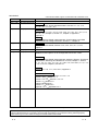
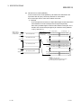
• When a stop error has occurred to the CPU module, the communication status varies
depending on the intelligent function module switch setting of GX Developer as shown below.
Set the communication status for when a stop error has occurred to the CPU module
according to the system specifications.
(1) When no setting (blank) is made to the switch 1 of the intelligent function module switch
setting
(a) Since the communication with the slave station is continued, values at the time of the CPU
module stop error occurrence are held as the output data sent to the slave station from the
QJ71PB92D.
(b) Input data received from slave stations are updated into the buffer memory of the
QJ71PB92D.
(2) When 0001H is set to the switch 1 of the intelligent function module switch setting
(a) Communications with slave stations are interrupted, and output data are not sent.
(b) Input data received from slave stations are held in the buffer memory of the
QJ71PB92D.
!
CAUTION
• When the PROFIBUS cable is laid, do not lay it close to main circuits or power lines.
They should be installed 100mm(3.9inch) or more from each other.
Not doing so could result in noise that would cause malfunctioning.
[INSTALLATION PRECAUTIONS]
!
CAUTION
• Use the programmable controller in an environment that meets the general specifications
contained in the CPU user's manual.
Using this programmable controller in an environment outside the range of the general
specifications may cause electric shock, fire, malfunction, and damage to or deterioration of
the product.
• While pressing the installation lever located at the bottom of module, insert the module fixing
tab into the fixing hole in the base unit until it stops.
Then, securely mount the module with the fixing hole as a supporting point.
If the module is not installed properly, it may cause the module to malfunction, fail or fall off.
Secure the module with screws especially when it is used in an environment where constant
vibrations or strong impact may be expected.
A-2
A-2
[INSTALLATION PRECAUTIONS]
!
CAUTION
• Tighten the screws within the range of specified torque.
If the screws are loose, it may cause the module to fallout, short circuits, or malfunction.
If the screws are tightened too much, it may cause damage to the screw and/or the module,
resulting in fallout, short circuits or malfunction.
• Be sure to shut off all phases of the external power supply used by the system before
mounting or removing the module.
Not ding so may cause electric shock or damage to the module.
• Do not touch the conductive area or electric parts of the module.
Doing so may cause module malfunctioning or breakdowns.
[WIRING PRECAUTIONS]
!
CAUTION
• Be sure to shut off all phases of the external power supply used by the system before wiring
PROFIBUS cables. If you not switch off the external power supply, it will cause failure or
malfunction of the module.
• Be careful not to let foreign matter such as filings or wire chips get inside the module. These
can cause fire, breakdowns and malfunctioning.
• Be sure to place the PROFIBUS cables in a duct or clamp them.
If not, dangling cables may be shifted or inadvertently pulled, resulting in damages to the
module or cables or malfunctions due to poor cable contact.
• When disconnecting the PROFIBUS cable from the module, do not pull by holding the cable
section. To disconnect the cable, make sure to hold the connector which is coupled with the
module. Do not attempt to pull the cable to disconnect it from the module. It could damage the
module or the cable, or cause malfunction due to a poor contact of the cable.
• A protective film is attached onto the module top to prevent foreign matter such as wire chips
from entering the module when wiring.
Do not remove the film during wiring.
Remove it for heat dissipation before system operation.
[STARTING AND MAINTENANCE PRECAUTIONS]
!
DANGER
• Before cleaning, be sure to shut off all phases of the external power supply used by the
system. Not doing so could cause electric shock.
A-3
A-3
[STARTING AND MAINTENANCE PRECAUTIONS]
!
CAUTION
• Never disassemble or modify the module.
This may cause breakdowns, malfunctioning, injury and/or fire.
• When using a wireless communication device such as a cellular phone, keep a distance of
25cm (9.85 inch) or more from the programmable controller in all directions.
Failure to do so can cause a malfunction.
• Be sure to shut off all phases of the external power supply before mounting or removing the
module. If you do not switch off the external power supply, it will cause breakdowns or
malfunction of the module.
• Set the ON/OFF select switch of the terminal resistor before the operation.
If the setting is switched during the operation, network error may occur, or error detection may
not be performed by error.
• Do not mount/remove the module onto/from the base unit more than 50 times (IEC61131-2compliant), after the first use of the product.
Failure to do so may cause the module to malfunction due to poor contact of connector.
• Before handling the module, always touch grounded metal, etc. to discharge static electricity
from the human body.
Failure to do so can cause the module to fail or malfunction.
[DISPOSAL PRECAUTIONS]
!
CAUTION
• When disposing of this product, treat it as industrial waste.
A-4
A-4
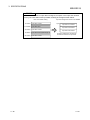
REVISIONS
* The manual number is given on the bottom left of the back cover.
Print Date
Dec., 2000
May, 2001
Apr., 2004
* Manual Number
Revision
SH (NA)-080127-A First edition
SH (NA)-080127-B Corrections
About the Generic Terms and Abbreviations, Section 2.1, 2.4, 4.1.3,
4.1.4, 5.1, 5.1.1, 5.4, 8.1, 8.2
SH (NA)-080127-C Corrections
Section 1.2, 2.1, 2.4, 3.1, 3.2.3, 3.3.2, 3.4.2, 4.1.4, 5.1, 5.1.1, 5.2.1, 5.3,
5.5.3, 6.1, 6.2, Chapter 7, Section 7.1, Chapter 9, Appendix 1,
Appendix 3
Additions
SAFETY PRECAUTIONS, About Manuals, Conformation to the EMC
Directive and Low Voltage Instruction, Section 7.1, Chapter 9
Aug., 2004
Jul., 2006
May, 2007
SH (NA)-080127-D Corrections
SAFETY PRECAUTIONS, Section 3.2.2, 3.2.3, 3.4.2, 5.1.1, 5.5.1,
Chapter 7
SH (NA)-080127-E The entire manual was reviewed.
SH (NA)-080127-F • Rewritten to include the QJ71PB92D-compatible function.
• Modified for descriptions of GX Configurator-DP Version 7.02C.
Corrections
SAFETY PRECAUTIONS, About Manuals, About the Generic Terms and
Abbreviations, Meanings and Definitions of Terms, Chapter 1, Section
1.1, 2.1, 2.4, 3.1, 3.2.1, 4.1.4, 5.1, 5.1.2 to 5.1.5, 5.3 to 5.5.2, 7.1.2, 7.1.4
to 7.5, 8.1 to 8.3, Chapter 9, Section 9.1
Additions
Section 4.3, 5.1.6, 7.1.1, 9.2 to 9.4.2, Appendix 1
Section number changes
Section 7.1(1)(a) to (b) Section 7.1.2 to 7.1.3
Section 7.1(2) Section 7.1.4
Section 7.2 to 7.3 Section 7.3 to 7.4
Section 7.4 Section 7.2
Chapter 9 Section 9.1
Section 9.1 Section 9.5
Appendix 1 to 3 Appendix 2 to 4
Japanese Manual Version SH-080126-F
This manual confers no industrial property rights or any rights of any other kind, nor does it confer any patent
licenses. Mitsubishi Electric Corporation cannot be held responsible for any problems involving industrial property
rights which may occur as a result of using the contents noted in this manual.
© 2000 MITSUBISHI ELECTRIC CORPORATION
A-5
A-5
INTRODUCTION
Thank you for purchasing the Mitsubishi Programmable Controller MELSEC-Q Series.
Before using the equipment, please read this manual carefully to develop full familiarity with the functions
and performance of the graphic operation terminal you have purchased, so as to ensure correct use.
Please forward a copy of this manual to the end user.
CONTENTS
SAFETY PRECAUTIONS ...................................................................................................................... A - 1
REVISIONS............................................................................................................................................ A - 5
INTRODUCTION.................................................................................................................................... A - 6
CONTENTS ........................................................................................................................................... A - 6
About Manuals ....................................................................................................................................... A - 9
Conformation to the EMC Directive and Low Voltage Instruction.......................................................... A - 9
About the Generic Terms and Abbreviations ......................................................................................... A -10
Meanings and Definitions of Terms ...................................................................................................... A -11
Product Structure ................................................................................................................................... A -12
1. OVERVIEW
1- 1 to 1- 4
1.1 QJ71PB92D Features ..................................................................................................................... 1- 3
2. SYSTEM CONFIGURATION
2.1
2.2
2.3
2.4
2- 1 to 2- 6
Applicable System ........................................................................................................................... 2When Used in Multiple CPU System ............................................................................................... 2Precautions for Configuring a System ............................................................................................. 2Checking the Function Version and Serial No. ................................................................................ 2-
3. SPECIFICATIONS
1
4
4
5
3- 1 to 3- 50
3.1 Performance Specifications ............................................................................................................. 3- 1
3.2 Network Configuration ..................................................................................................................... 3- 3
3.2.1 Basic configuration .................................................................................................................... 3- 3
3.2.2 Applicable configuration ............................................................................................................ 3- 5
3.2.3 Number of connectable slaves .................................................................................................. 3- 9
3.3 I/O Signal ......................................................................................................................................... 3-12
3.3.1 I/O signal list .............................................................................................................................. 3-12
3.3.2 I/O signal detail description ....................................................................................................... 3-13
3.4 Buffer Memory List ........................................................................................................................... 3-22
3.4.1 Buffer memory/configuration ..................................................................................................... 3-22
3.4.2 Buffer memory detailed description........................................................................................... 3-23
4. FUNCTIONS
4- 1 to 4- 18
4.1 Functions for Exchanging with Slaves ............................................................................................. 4- 1
4.1.1 I/O data exchange ..................................................................................................................... 4- 1
4.1.2 Global control functions............................................................................................................. 4- 3
4.1.3 Word data swap function........................................................................................................... 4- 7
4.1.4 I/O data separation prevention function .................................................................................... 4-10
A-6
A-6
4.2 Operation Mode ............................................................................................................................... 4-13
4.2.1 Normal service mode (MODE 0) ............................................................................................... 4-15
4.2.2 Extended service mode (MODE E) ........................................................................................... 4-16
4.3 Output Status Setting for the Case of a CPU Stop Error....................................................................... 4-17
5. PROCEDURES BEFORE SYSTEM OPERATION
5- 1 to 5- 34
5.1 Procedures before Operation........................................................................................................... 5- 1
5.1.1 Parameter setting procedure..................................................................................................... 5- 6
5.1.2 Master parameters .................................................................................................................... 5- 7
5.1.3 Bus parameters ......................................................................................................................... 5-10
5.1.4 Slave parameters ...................................................................................................................... 5-12
5.1.5 Automatic refresh parameters .................................................................................................... 5-15
5.1.6 Intelligent function module switch setting................................................................................... 5-23
5.2 Installation ........................................................................................................................................ 5-25
5.2.1 Handling precautions................................................................................................................. 5-25
5.2.2 Installation environment ............................................................................................................ 5-25
5.3 Part Names and Settings ................................................................................................................. 5-26
5.4 Execution Method for Self-diagnosis ............................................................................................... 5-28
5.5 Wiring ............................................................................................................................................... 5-30
5.5.1 PROFIBUS cable wiring ............................................................................................................ 5-30
5.5.2 Terminator ................................................................................................................................. 5-32
5.5.3 Precautions against wiring ........................................................................................................ 5-33
5.6 Maintenance and Inspection ............................................................................................................ 5-34
6. COMMUNICATION TIME
6- 1 to 6- 5
6.1 Bus Cycle Time ................................................................................................................................ 6- 1
6.2 Transmission Delay Time ................................................................................................................ 6- 5
7. PROGRAMMING
7- 1 to 7- 23
7.1 Communication Using Automatic Refresh Setting........................................................................... 7- 4
7.1.1 When using GX Configurator-DP Version 7.01B or later ........................................................... 7- 4
7.1.2 When using GX Configurator-DP Version 5 to 7.00A ................................................................ 7- 7
7.1.3 When using GX Configurator-DP Version 4............................................................................... 7- 9
7.1.4 Program example ....................................................................................................................... 7-15
7.2 Communication Using Dedicated Instruction................................................................................... 7-17
7.3 Normal Service Mode (MODE 0) Using MOV Instruction ................................................................ 7-19
7.4 Extended Service Mode (MODE E) Using MOV Instruction............................................................ 7-21
7.5 Execution of Global Control ............................................................................................................. 7-23
8. DEDICATED INSTRUCTIONS
8- 1 to 8- 4
8.1 Dedicated Instruction List and Available Devices ............................................................................ 8- 1
8.2 G.BBLKRD ....................................................................................................................................... 8- 3
8.3 G.BBLKWR ...................................................................................................................................... 8- 4
A-7
A-7
9. TROUBLESHOOTING
9- 1 to 9- 20
9.1 Error Check Using the LEDs and Corrective Actions ...................................................................... 9- 2
9.2 When Parameters cannot be Written from GX Configurator-DP ..................................................... 9- 4
9.3 When Communication with Slave Stations is Not Possible ............................................................. 9- 6
9.4 Error Code........................................................................................................................................ 9-10
9.4.1 Error codes for the QJ71PB92D............................................................................................... 9-12
9.4.2 Error codes for the QJ71PB92V (QJ71PB92D-compatible function)....................................... 9-15
9.5 Initialization of Flash ROM When Parameters are Corrupted ......................................................... 9-18
APPENDICES
App - 1 to App - 8
Appendix 1 Replacement with the QJ71PB92V (QJ71PB92D-compatible function) ....................... App - 1
Appendix 1.1 Precautions for replacing the QJ71PB92D with the QJ71PB92V ........................... App - 2
Appendix 2 Differences between QJ71PB92D and A1SJ71PB92D/AJ71PB92D ............................. App - 4
Appendix 3 Extended Trouble Information of Mitsubishi's Slaves ..................................................... App - 5
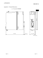
Appendix 4 External Dimensions ....................................................................................................... App - 6
INDEX
A-8
Index 1 to Index - 2
A-8
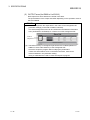
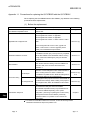
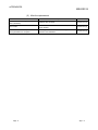
About Manuals
The following are manuals related to this product.
Please purchase them if necessary.
Related Manuals
Manual Name
GX Configurator-DP Version 7 Operating Manual
Explains the overview, installation method, screen operations, etc. of GX Configurator-DP Version 7.
(Sold separately)
PROFIBUS-DP Master Module User’s Manual
Explains the overview, system configuration, specifications, functions, procedures before system
operation, programming and dedicated instructions of QJ71PB92V.
(Sold separately)
Manual Number
SH-080579ENG
(13JU54)
SH-080572ENG
(13JR84)
Inquiries can be made to :
MITSUBISHI ELECTRIC EUROPE Factory Automation
Gothaer Strasse 8 D-40880 Ratingen Germany
Phone : +49(21 02)486-0
Fax : +49(21 02)486-717
Conformation to the EMC Directive and Low Voltage Instruction
When incorporating the Mitsubishi programmable controller into other machinery or
equipment and keeping compliance with the EMC and low voltage directives, refer to
Chapter 3 "EMC Directive and Low Voltage Instruction" of the User’s Manual
(hardware) supplied with your CPU module or base unit.
The CE logo is printed on the rating plate of the programmable controller, indicating
compliance with the directives.
Note that no additional measures are necessary for this product to make compliance
with the directives.
A-9
A-9
About the Generic Terms and Abbreviations
Unless otherwise specified, this manual uses the following generic terms and
abbreviations to describe the Type QJ71PB92D PROFIBUS-DP interface module.
Generic Term/Abbreviation
QJ71PB92D
QJ71PB92V
QJ71PB92V
(QJ71PB92D-compatible
function)
QCPU
CPU module
GX Developer
GX Configurator-DP
PROFIBUS-DP
BBLKRD
BBLKWR
A - 10
Description of the abbreviation/general terms
Abbreviation for the QJ71PB92D PROFIBUS-DP interface module.
Abbreviation for the QJ71PB92V PROFIBUS-DP master module.
Generic term representing the QJ71PB92V that is operating with the QJ71PB92Dcompatible function.
Generic term for Q00JCPU, Q00CPU, Q01CPU, Q02CPU, Q02HCPU, Q06HCPU,
Q12HCPU, Q25HCPU, Q12PHCPU, Q25PHCPU, Q03UDCPU, Q04UDHCPU and
Q06UDHCPU modules.
Generic product name for SWnD5C-GPPW-E, SWnD5C-GPPW-EA, SWnD5CGPPW-EV, and SWnD5C-GPPW-EVA. ("n" means version 4 or later.)
"-A" and "-V" mean "volume license product" and "version-upgrade product"
respectively.
Configuration tool for QJ71PB92D.
Generic term of the product model SWnD5C-PROFID-E.
("n" means version 4 or later.)
Abbreviation of PROFIBUS-DP network.
Abbreviation for G. BBLKRD.
Abbreviation for G. BBLKWR.
A - 10
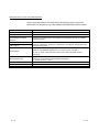
Meanings and Definitions of Terms
The following explains the meanings and definitions of the terms used in this manual.
Term
Description
A basic version of PROFIBUS-DP.
The following functions are executable:
PROFIBUS-DPV0
• I/O data exchange
• Trouble information notification
etc.
A PROFIBUS-DP version for which the following functions have been added to the basic
functionality of PROFIBUS-DPV0.
PROFIBUS-DPV1
• Acyclic communication
• Alarm function
etc.
A PROFIBUS-DP version for which the following functions have been added to the
PROFIBUS-DPV1 functionality.
PROFIBUS-DPV2
• Time stamping
etc.
A device exchanging I/O data with a slave stations. (QJ71PB92V, QJ71PB92D, etc)
Class 1 master station
A device that communicates with slave stations and checks their FDL address settings
and/or operation states.
Class 2 master station
The class 2 master station is used as a master station for supervising the network, which
can start, maintain, and diagnose the system.
A device that exchanges I/O data with a class 1 master station. (QJ71PB93D, ST1H-PB,
Slave station
etc)
A device used to connect different segments of PROFIBUS-DP.
Repeater
A terminating resistor that is connected to either end of each segment on PROFIBUSBus terminator
DP.
Software used to set bus parameters, slave parameters, etc. and to write them to a
Configuration tool
master station. (GX Configurator-DP, etc.)
An electronic file that contains parameters of a slave station.
GSD file
The GSD file is used to set up the slave parameters on GX Configurator-DP.
The numbers assigned to a master station and slave station.
Station number
The station number is set within the range from 0 to 125.
The parameter used for the communication setting of PROFIBUS-DP.
Bus parameter
The bus parameter is set up on the GX Configurator-DP.
The parameter used for the settings (FDL address, transmission speed, etc.) of the
Master parameter
QJ71PB92D.
The master parameter is set up on the GX Configurator-DP.
The parameter for a slave station, which is set on the master station.
Slave parameter
The slave parameter is set up on the GX Configurator-DP.
The setting items are described on the GSD File.
I/O CONFIGURATION DATA Information on I/O configuration of a slave station.
This function allows I/O data exchange between a class 1 master station and slave
I/O data exchange
stations.
This function enables synchronization command transmission for I/O data from a class 1
Global control
master station to slave station.
Trouble information of PROFIBUS-DP, which is detected by a master station or notified
Trouble information
by a slave station.
Expansion communication
Trouble information specific to each slave station.
trouble information
Each of slave stations notifies of it to the master station when an error is detected.
PROFIBUS-DP processing time for the master station to perform cyclic transfer with
Bus cycle time
each slave station.
QJ71PB92D-compatible
The function used to replace the QJ71PB92D with the QJ71PB92V.
function
The model QJ71PB92V, PROFIBUS-DP master module has this function.
A - 11
A - 11
Product Structure
The product structure of this product is given in the table below.
Model
QJ71PB92D
A - 12
Product Name
QJ71PB92D PROFIBUS-DP interface module
Quantity
1
A - 12
1 OVERVIEW
MELSEC-Q
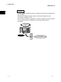
1. OVERVIEW
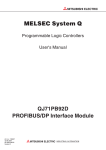
This user’s manual describes the following modules:
The model QJ71PB92D, PROFIBUS-DP interface module (QJ71PB92D)
The model QJ71PB92V, PROFIBUS-DP master module, which is operating with the
QJ71PB92D-compatible function (QJ71PB92V (QJ71PB92D-compatible function))
When explain separately, which is used to connect a MELSEC-Q series programmable
controller to a PROFIBUS-DP network.
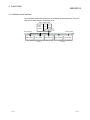
The QJ71PB92D operates as a class 1 master station in the PROFIBUS-DP network.
Class 1 master station (QJ71PB92D)
Slave station (QJ71PB93D)
Slave station (MELSEC-ST system)
ST 1P SD
S T 1 H-P B
Bus terminator
RUN
S YS
AUX.
E RR
Slave station
ST1PDD
RUN
11
ERR
21
RU N
11
ERR
RUN
ER R
RUN
ERR
RUN
ERR
21
AUX
R ELEASE
RESET
PR OFIBUS I/F
Bus terminator
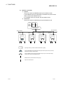
(1) Distinctions between the QJ71PB92D and the QJ71PB92V
(QJ71PB92D-compatible function)
Operations of the QJ71PB92D and QJ71PB92V (QJ71PB92D-compatible
function) are described as follows:
(a) Operations that are common to the QJ71PB92D and the QJ71PB92V
(QJ71PB92D-compatible function)
Described as the QJ71PB92D.
(b) Operations that are different between the QJ71PB92D and the QJ71PB92V
(QJ71PB92D-compatible function)
Explained separately, using the following icons.
QJ71PB92D
: Operations of the QJ71PB92D
QJ71PB92V
: Operations of the QJ71PB92V (QJ71PB92D-compatible function)
(92D-compatible)
POINT
When replacing the QJ71PB92D with the QJ71PB92V, refer to Appendix 1.
1-1
1-1
1
1 OVERVIEW
MELSEC-Q
REMARK
1
The QJ71PB92D-compatible function is provided for replacing the QJ71PB92D with
the QJ71PB92V.
When the QJ71PB92D has failed, replace it with the QJ71PB92V using the
QJ71PB92D-compatible function.
Since the existing network configuration or sequence programs for the QJ71PB92D
can be utilized, a faulty QJ71PB92D can be smoothly replaced with the
QJ71PB92V.
QJ71PB92D
failed
Replaced
QJ71PB92V
(QJ71PB92D-compatible function)
1-2
1-2
1 OVERVIEW
MELSEC-Q
1.1 QJ71PB92D Features
(1) Class 1 master station on PROFIBUS-DP
The QJ71PB92D complies with EN50170, and operates as a class 1 master
station on PROFIBUS-DP systems.
The QJ71PB92D supports the PROFIBUS-DPV0 function.
PROFIBUS-DPV1 and PROFIBUS-DPV2, which are extended versions of
PROFIBUS-DP, are not supported.
(a) Up to 60 slave stations are connectable
Up to 60 slave stations can be connected to a single QJ71PB92D, enabling
the I/O data exchange of max. 3840 bytes. (Input data: max.1920 bytes,
Output data: max.1920 bytes) (Refer to Section 4.1.1)
(b) Trouble information can be easily acquired
Trouble or extended trouble information of an error occurred on a slave
station during I/O data exchange can be easily acquired using the buffer
memory and I/O signals. (Refer to Section 3.3, 3.4)
(c) Supporting the global control function
By sending services (SYNC, UNSYNC, FREEZE, UNFREEZE) to each
slave station in a group, synchronous control of slave station I/O data is
available. (Refer to Section 4.1.2)
Service Name
Description
SYNC
This service is for synchronizing the output status of slave stations.
In the SYNC mode, the output status of a slave station is refreshed
each time it receives the SYNC service.
While no SYNC service is received, the output status is held.
UNSYNC
This service is for ending the SYNC mode.
FREEZE
This service is for synchronizing the input status of slave stations.
In the FREEZE mode, the input status of a slave station is refreshed
each time it receives the FREEZE service.
While no FREEZE service is received, the input status is held.
UNFREEZE
This service is for ending the FREEZE service.
(2) I/O data separation prevention
Using the automatic refresh setting in GX Configurator-DP or dedicated
instructions (BBLKRD/BBLKWR) ensures data separation prevention when
reading/writing I/O data from the QJ71PB92D buffer memory. (Refer to Section
4.1.4)
(3) Easy parameter setup
Use of GX Configurator-DP enables bus parameters, master parameters, slave
parameters, and various other parameters to be easily set up. (Refer to Section
5.1.1 to 5.1.5)
1-3
1-3
1 OVERVIEW
MELSEC-Q
(4) Swapping of I/O data
The upper and lower bytes can be reversed (swapped) in word units when I/O
data is sent or received. (Refer to Section 4.1.3)
This simplifies programming as you no longer need to create a program for
swapping the upper and lower bytes on the QJ71PB92D or slave station.
(5) Output status setting for the case of a CPU stop error
(Continue/Stop of I/O data exchange)
For the case of a CPU stop error on a CPU module where the QJ71PB92D is
mounted, whether to continue or stop I/O data exchange with slave station can
be specified. (Refer to Section 4.3)
(6) Compatibility with multiple CPU system
Even when a plurality of CPU modules are installed through the multiple CPU
system, this model can be controlled by any CPU module.
(7) Self-diagnosis function included
The self-diagnosis function allows testing of hardware such as internal memories.
(Refer to Section 5.4)
1-4
1-4
2 SYSTEM CONFIGURATION
MELSEC-Q
2. SYSTEM CONFIGURATION
This chapter describes the system configuration of QJ71PB92D.
2.1 Applicable System
2
This section describes applicable systems.
(1) Mountable modules, No. of mountable modules, and mountable
base unit
(a) When mounting to CPU module
The following shows the mountable CPU modules, No. of mountable
modules, and mountable base unit of the QJ71PB92D.
Power shortage may occur depending on the combination with other
mounted modules or the number of mounted modules.
When mounting modules, pay attention to the power supply capacity.
When the power shortage occurs, review the combination of modules to be
mounted.
Mountable CPU module
CPU type
CPU model name
Q00JCPU
Basic model
QCPU
No. of mountable
modules 1
Mountable base unit
Main base unit
2
Extension base unit
Up to 8
Q00CPU
Up to 24
Q01CPU
Q02CPU
Q02HCPU
High Performance
Q06HCPU
model QCPU
Q12HCPU
Programmable
controller CPU
Up to 64
Q25HCPU
Q12PHCPU
Process CPU
Q25PHCPU
Redundant CPU
Q12PRHCPU
Q25PRHCPU
Q02UCPU
Universal model
QCPU
Up to 64
Not mountable
Not mountable
Q03UDCPU
Q04UDHCPU
Up to 64
Q06UDHCPU
: Mountable,
: Not
mountable
1 Limited to the range of the number of I/O points in the CPU module
2 Mountable on any I/O slot of the mountable base unit.
POINT
(1) The number of mountable modules is restricted depending on the automatic
refresh setting on the QJ71PB92D.
For details, refer to Section 5.1.5.
(2) Use a QCPU whose first five digits of serial No. is 02092 or later to use the
separation prevention function. If this function is used in any other models, I/O
data may be identified as invalid values.
2-1
2-1
2 SYSTEM CONFIGURATION
MELSEC-Q
(b) When mounting to remote I/O station of MELSECNET/H
The QJ71PB92D cannot be mounted to remote I/O station of the
MELSECNET/H.
When using the QJ71PB92D in the MELSECNET/H remote I/O network,
mount it to a CPU module of the master station.
2
(2) Compatibility with multiple CPU system
Please refer to the QCPU User's Manual (Multiple CPU System) before using the
QJ71PB92D in the multiple CPU system.
(a) Compatible QJ71PB92D
The function version of the QJ71PB92D has been "B" from the first release
and it supports the multiple CPU system.
(3) Online module change
The QJ71PB92D does not support the online module change.
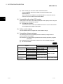
(4) Compatible software packages
The following shows the compatibility between software packages and the
system using the QJ71PB92D.
GX Developer: For setting QCPU parameters and creating sequence programs
(Required)
GX Configurator-DP: Configuration software for the QJ71PB92D (Required)
(a) For the QJ71PB92D
QJ71PB92D
System
GX Developer
Single CPU system
Version 7 or later
Multiple CPU system
Version 8 or later
Q02/Q02H/Q06H/
Single CPU system
Version 4 or later
Q12H/Q25HCPU
Multiple CPU system
Version 6 or later
Q00J/Q00/Q01CPU
Q12PH/Q25PHCPU
2-2
Software Package
Single CPU system
Multiple CPU system
Q03UD/Q04UDH/
Single CPU system
Q06UDHCPU
Multiple CPU system
GX Configurator-DP
Version 5 or later
Version 4 or later
Version 7.10L or later
Version 8.48A or later
Version 7.02C or later
2-2
2 SYSTEM CONFIGURATION
MELSEC-Q
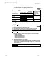
(b) For the QJ71PB92V (QJ71PB92D-compatible function)
QJ71PB92V
(92D-compatible)
Software Package
System
Q00J/Q00/Q01CPU
GX Developer
Single CPU system
Version 7 or later
Multiple CPU system
Version 8 or later
Q02/Q02H/Q06H/Q12H/ Single CPU system
Version 4 or later
Q25HCPU
Version 6 or later
Multiple CPU system
Q12PH/Q25PHCPU
Single CPU system
Multiple CPU system
GX Configurator-DP
Version 5 to 6
Version 7.01B or
later *1
Version 4 to 6
Version 7.01B or
Version 7.10L or later later*1
Q03UD/Q04UDH/
Single CPU system
Version 8.48A or
Version 7.02C or
Q06UDHCPU
Multiple CPU system
later
later
1 GX Configurator-DP Version 7.01B, only the Web-based online access function
cannot be used.
POINT
QJ71PB92V
(92D-compatible)
GX Configurator-DP Version 7.00A cannot be used.
For GX Configurator-DP Version 7.00A, upgrade it to Version 7.01B or later.
For version upgrades, please consult your local Mitsubishi representative.
REMARK
The following configuration software programs cannot be used on QJ71PB92D.
SW0D5C PROFIMAP
MELSEC PROFIMAP Version 1
MELSEC PROFIMAP Version 2
MELSEC PROFIMAP Version 3
(5) Replacement with the QJ71PB92V
When replacing the QJ71PB92D with the QJ71PB92V (QJ71PB92D-compatible
function), use the QJ71PB92V whose serial No. (first five digits) is 09052 or later.
(Refer to Section 2.4.)
POINT
When replacing the QJ71PB92D with the QJ71PB92V, refer to Appendix 1.
2-3
2-3
2 SYSTEM CONFIGURATION
MELSEC-Q
2.2 When Used in Multiple CPU System
When using QJ71PB92D in the multiple CPU system, take care of the following.
The control of QJ71PB92D is performed by any QCPU.
A total of merely 64 sheets of QJ71PB92D is installed for each system. It is not the
mountable number of sheets for each controlled QCPU, but the total number of
sheets controlled by all QCPUs.
2.3 Precautions for Configuring a System
(1) Precaution for parameter writing
(a) If a parameter is written to the QJ71PB92D that is exchanging I/O
data, the I/O data communication is suspended.
It is restarted after completion of parameter writing.
(b) Do not change the operation mode from the sequence program during
parameter writing.
Doing so may disable proper station number setting or mode change.
(c) Do not write parameters from multiple GX Configurator-DPs to a single
QJ71PB92D at the same time.
Doing so makes the parameter values of the QJ71PB92D incorrect.
(2) Operations performed with the module READY signal (X1D) ON
When performing the following operations, make sure the module READY signal
(X1D) is ON.
To switch over the operation mode with Y11/X11, using the sequence program.
To set parameters.
If the status of module READY signal (X1D) is ignored and data is read from or
written in the buffer memory, the CPU module may detect an error to stop the
sequence calculation.
2-4
2-4
2 SYSTEM CONFIGURATION
MELSEC-Q
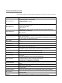
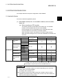
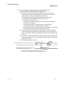
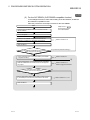
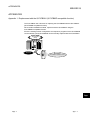
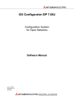
2.4 Checking the Function Version and Serial No.
This section explains how to check the function version and serial No. of the
QJ71PB92D.
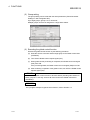
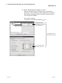
(1) Checking the "Rating plate" on the side of the module
The serial No. and function version of the module are printed in the SERIAL
section of the rating plate.
Serial No. (Upper 5 digits)
Function version
06042
Conformed standard
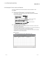
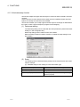
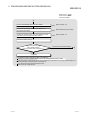
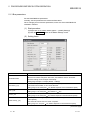
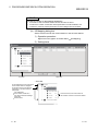
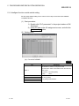
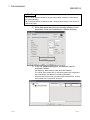
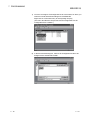
(2) Checking through GX Developer
The following explains how to check the serial No. and function version of the
module through GX Developer.
The serial No. and function version are displayed on the "Product information list"
or "Module's Detailed Information" screen of GX Developer.
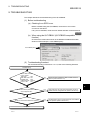
The procedure for checking the serial No. and function version on the "Product
information list" screen is shown below.
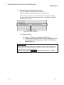
[Start Procedure]
"Diagnostics"
2-5
"System monitor"
"Product inf. List"
2-5
2 SYSTEM CONFIGURATION
MELSEC-Q
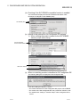
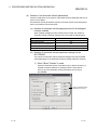
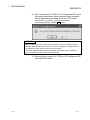
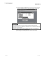
[Serial No., Ver., Product No.]
• The serial No. of the module is displayed in the "Serial No." column.
• The function version of the module is displayed in the "Ver." column.
• The serial No. (Product No.) shown on the rating plate is displayed in the
*1
"Product No." column.
Note that "-" is displayed in the "Product No." column for the QJ71PB92D
since this module is not supporting Product No. display.
*1 The Product No. is displayed in the column only when the Universal
model QCPU is used.
POINT
The serial No. described on the rated plate may not match with the serial No.
displayed on the product information of GX Developer.
The serial No. on the rated plate describes the management information of the
product.
The serial No. displayed on the product information of GX Developer describes the
function information of the product.
The function information of the product is updated when adding functions.
2-6
2-6
3 SPECIFICATIONS
MELSEC-Q
3. SPECIFICATIONS
This chapter explains the performance and transmission specifications of the
QJ71PB92D.
For details of the general specifications, refer to the QCPU User’s Manual (Hardware
Design, Maintenance and Inspection).
3.1 Performance Specifications
Item
Specifications
PROFIBUS-DP station type
Electrical standard/characteristics
EIA-RS485 compliant
Medium
Shielded twisted pair cable (Refer to Section 5.5.1)
Network topology
Bus topology (Tree topology when repeaters are used)
• Between master station and master station: Token passing method
Data link method
Transmission specifications
3
Class 1 master station
• Between master station and slave station: Polling method
Encording method
Transmission speed *
NRZ
1
9.6 kbps to 12 Mbps (Refer to (1) in this section)
Transmission distance
Differs depending on the transmission speed (Refer to (1) in this section)
Max. No. of repeaters
3 repeaters
Number of connectable modules (Per segment)
32 per segment*2 (including repeater(s))
Number of connectable modules (Per network)
126 per network*2 (total of master stations and slave stations (Refer to Section
3.2.1 (2)))
Max. No. of slave stations (Per QJ71PB92D)
60 per QJ71PB92D*2
I/O data
Input data
• Normal service mode: 32 bytes per slave station
Output data
• Normal service mode: 32 bytes per slave station
size
• Extended service mode: Max. 1920 bytes (Max. 244 bytes per slave station)
• Extended service mode: Max. 1920 bytes (Max. 244 bytes per slave station)
Number of writes to flash ROM
Max. 100000 times
No. of occupied I/O points
32 (I/O assignment: 32 intelligent points)
Internal current consumption (5VDC)
0.57 A
External dimensions
98(3.86 in.) (H)
Weight
0.15 kg
27.4(1.08 in.) (W)
90(3.54 in.) (D) [mm]
1 The transmission speed is controlled within 0.3%. (PROFIBUS part1)
2 When a slave used is greater than 32 bytes in the maximum data length of the error information, Max. No. of stations and the Max.
No. of slave stations may be less than the above values.
This is because the maximum data length of the slave station error information that the QJ71PB92D can receive varies with the
minimum station number and maximum station number of the slave stations set in the parameters. Refer to Section 3.2.3 for
details.
For the noise immunity, withstand voltage, insulation resistance and others in the
programmable controller system using this module, refer to the power supply
module specifications given in the used QCPU User’s Manual (Hardware Design,
Maintenance and Inspection).
3-1
3-1
3 SPECIFICATIONS
MELSEC-Q
(1) Transmission distance
Transmission Speed
Max. Transmission Distance when
Transmission Distance
Repeater is Used *1
9.6 kbps
1200 m (3937 ft.)/segment
4800 m (15748 ft.)/network
187.5 kbps
1000 m (3281 ft.)/segment
4000 m (13123 ft.)/network
500 kbps
400 m (1312 ft.)/segment
1600 m (5249 ft.)/network
1.5 Mbps
200 m (656 ft.)/segment
800 m (2625 ft.)/network
100 m (328 ft.)/segment
400 m (1312 ft.)/network
19.2 kbps
93.75 kbps
3 Mbps
3
6 Mbps
12 Mbps
1 The max. transmission distance in the table above is based on the case where 3 repeaters are used.
The calculation formula for the transmission distance extended using a repeater(s) is:
Max. transmission distance [m/network] = (Number of repeaters + 1)
3-2
Transmission distance [m/segment]
3-2
3 SPECIFICATIONS
MELSEC-Q
3.2 Network Configuration
3.2.1 Basic configuration
This section explains the basic PROFIBUS-DP configuration for using the
QJ71PB92D as a class 1 master station.
(1) System equipment
The following table shows the equipment required for the PROFIBUS-DP
system.
System Equipment
Description
Class 1 master station
QJ71PB92D
Configuration tool
• For the QJ71PB92D QJ71PB92D
GX Configurator-DP Version 4 or later
• For the QJ71PB92V (QJ71PB92D-compatible function) *1
QJ71PB92V
(92D-compatible)
GX Configurator-DP Version 4 to 6
GX Configurator-DP Version 7.01B or later *2
Slave station
QJ71PB93D, ST1H-PB, etc.
Repeater
Required when 32 or more slave station are connected
PROFIBUS cable
Bus terminator
Refer to Section 5.5.1
1 GX Configurator-DP Version 7.00A cannot be used.
2 GX Configurator-DP Version 7.01B, only the Web-based online access function
cannot be used.
3-3
3-3
3 SPECIFICATIONS
MELSEC-Q
(2) Network configuration
In the PROFIBUS-DP system configuration, the following conditions must be
satisfied:
(a) Number of connectable modules in an entire network (With repeaters are
used)
1
Master station * + Slave station ≤ 126
1 Including the QJ71PB92D
(b) Number of connectable modules per segment
1
2
Master station * + Slave station + repeaters * ≤32
1 Including the QJ71PB92D
2 A repeater is counted for both segments.
(c) No. of repeaters
Up to 3 repeaters can be used for communication between the
QJ71PB92D and any slave station.
(d) Number of connectable slave stations per QJ71PB92D
Up to 60 slave stations can be connected to a single QJ71PB92D.
(e) Multi-master system (The QJ71PB92D only
QJ71PB92D
)
When using other vendor's products as master stations
When a communication chip of ASPC2 STEP C mode or equivalent is
used, the master station cannot be connected to the PROFIBUS-DP in
which the QJ71PB92D is included.
To use a master station with such a communication chip, configure
another
network.
For the communication chip currently used, consult its manufacturer.
3-4
3-4
3 SPECIFICATIONS
MELSEC-Q
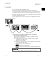
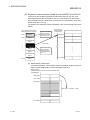
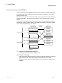
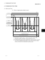
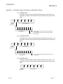
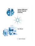
3.2.2 Applicable configuration
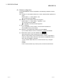
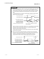
(1) Maximum configuration with no connected
Master station (QJ71PB92D): 1
Slave station: 31
Class 1 master station
(Station No.0)
Power
supply
module
: Connection points counted
as number of modules
QJ71
QCPU PB92D
Segment 1
Bus terminator
Bus terminator
Slave station
(Station No.1)
Slave station
(Station No.2)
Slave station
(Station No.31)
Slave station: 31 slaves
A maximum of 32 slaves can be connected to 1 segment.
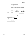
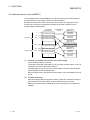
(2) Maximum configuration with a repeater connected
Master station (QJ71PB92D): 1
Slave station: 60
Repeater: 1
Class 1 master station
(Station No.0)
Power
supply
module
QCPU
: Connection points counted
as number of modules
QJ71
PB92D
Segment 1
Bus terminator
Slave station
(Station No.1)
Bus terminator
Slave station
(Station No.2)
Slave station
(Station No.30)
Repeater 1
Slave station: 30 slaves
Segment 2
Slave station
(Station No.31)
Slave station
(Station No.32)
Slave station
(Station No.60)
Slave station: 30 slaves
In the above configuration a maximum of 60 slaves can be connected.
3-5
3-5
3 SPECIFICATIONS
MELSEC-Q
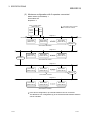
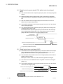
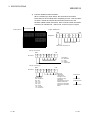
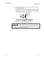
(3) Maximum configuration with 3 repeaters connected
Master station (QJ71PB92D): 1
Slave station: 60
Repeaters: 3
Class 1 master station
(Station No.0)
Power
supply
module
:Connection points counted
as number of modules
QJ71
QCPU PB92D
Segment 1
Bus terminator
Bus terminator
Slave station
(Station No.1)
Slave station
(Station No.2)
Slave station
(Station No.18)
Repeater 1
Slave station: 18 slaves
Segment 2
Slave station
(Station No.19)
Slave station
(Station No.20)
Slave station
(Station No.35)
Repeater 2
Slave station: 17 slaves
Segment 3
Slave station
(Station No.36)
Slave station
(Station No.37)
Slave station
(Station No.44)
Repeater 3
Slave station: 9 slaves
Segment 4
Slave station
(Station No.45)
Slave station
(Station No.46)
Slave station
(Station No.60)
Slave station: 16 slaves
In the above configuration, up to 60 slave stations can be connected.
The difference from configuration (2) in the fact that the transmission distance
can be extended.
3-6
3-6
3 SPECIFICATIONS
MELSEC-Q
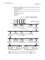
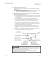
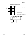
(4) Maximum configuration with multiple master stations connected
(Multi-master system)
More than one master station with different station numbers can be connected to
the same network.
By using three QJ71PB92Ds as shown below, up to 123 slave stations can be
connected.
Master station (QJ71PB92D): 3
Slave station: 123
Repeaters: 4
First class-1 master station (Station No.0)
Second class-1 master station (Station No.1)
Third class-1 master station (Station No.2)
Power
supply
module
QCPU QJ71 QJ71 QJ71
PB92D PB92D PB92D
: Connection points counted
as number of modules
Segment 1
Bus terminator
1M-1
1M-2
Slave station
(Station No.3)
Bus terminator
1M-28
Slave station
(Station No.4)
Slave station
(Station No.30)
Repeater 1
Slave station: 28 slaves
Segment 2
1M-29
1M-30
1M-58
Slave station
(Station No.31)
Slave station
(Station No.32)
Slave station
(Station No.60)
Repeater 2
Slave station: 30 slaves
Segment 3
2M-1
2M-2
2M-29
Slave station
(Station No.61)
Slave station
(Station No.62)
Slave station
(Station No.89)
Repeater 3-1
Repeater 3-2
Slave station: 29 slaves
Segment 4
Segment 5
2M-30
2M-60
3M-1
3M-5
Slave station
(Station No.90)
Slave station
(Station No.120)
Slave station
(Station No.121)
Slave station
(Station No.125)
Slave station: 31 slaves
3-7
Slave station: 5 slaves
1M-
: Slave station controlled by the 1st class-1 master station (Station No. 0). (
2M-
: Slave station controlled by the 2nd class-1 master station (Station No. 1). (
indicates count No.)
indicates count No.)
3M-
: Slave station controlled by the 3rd class-1 master station (Station No. 2). (
indicates count No.)
3-7
3 SPECIFICATIONS
MELSEC-Q
POINT
In configurations that use multiple master stations (multimaster configuration),
when reconnecting a cable after disconnecting a PROFIBUS cable for 1 master
that is exchanging data at a low baud rate, the communications of the master for
which the cable is not disconnected could stop and the slave output could be
turned off.
To prevent this, the master PROFIBUS cable must be secured with a screw.
In addition, there is a high possibility that the above phenomena can be avoided if
care is taken with the following points when configuring a system.
(1) Set the slave watchdog timer setting value to larger than (TTR × G)/BR.
However,
TTR : Target token rotation time (Unit: Bit Time)
G:
Gap update factor
BR : Baud rate (Unit: bps)
(2) Use a high baud rate.
(3) The HSA (Highest Station Address) value is made to match the maximum
station No. that is actually connected.
3-8
3-8
3 SPECIFICATIONS
MELSEC-Q
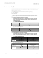
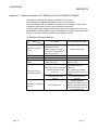
3.2.3 Number of connectable slaves
Please calculate the number of the slave which can be connected under the following
(1) and (2) conditions.
(1) Restrictions on maximum data length of slave station error
information
The maximum data length of the slave station error information that the
QJ71PB92D can receive varies with the minimum station number and maximum
station number of the slave stations set in the parameters, and can be calculated
using the following expression.
Maximum data length of acceptable error information [bytes] = Min
12600
, 244
N - 10
N = Min((a - b + 1) 5, 300)
a: Maximum station number of slave station
b: Minimum station number of slave station
Min(a, b) = A or B, whichever is smaller
If the maximum data length (Max_Diag_Data_Len) of the error information
described in the GSD file of a slave station is greater than the value calculated by
the above expression, normal communication may not be made with that slave
station.
If normal communication cannot be made, try the following methods:
(a) Set the station numbers of the slave stations with no unused numbers in
between.
(b) Make setting on the slave station side to shorten the maximum data length of
the error information. (If possible)
(c) Using two or more QJ71PB92D's, reduce the number of slave stations per
module.
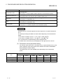
(2) Restrictions on parameter data length of slave station
The parameter size which can be set in QJ71PB92D should meet the following
formula.
Note that the system construction which does not meet the following formula
causes the error of 1302H. (Refer to Section 3.4.2 (4))
5+
n
i=1
(number of parameter blocks of each slave station)
128
n = number of slave stations
(number of parameter blocks of each slave station) = sum total of the numbers of parameter
blocks calculated by each slave station
The number of parameter blocks for each station is decided by the parameter
size of the station as follows.
Parameter size of each
slave station
246 bytes or less
247 to 480 bytes
481 to 720 bytes
721 to 762 bytes
3-9
Number of blocks of each
slave station
1 block
4 blocks
5 blocks
6 blocks
3-9
3 SPECIFICATIONS
MELSEC-Q
Calculate the parameter size of each slave station using the following formula.
Parameter size of each slave station = 31 + (User_Param data length)
+ (configuration data length) +
(a) User_Param data length
The value of User_Prm_Data usage on the screen displayed when Select
Modules is selected on the slave station setting screen of GX ConfiguratorDP.
(b) Configuration data length
The value differs depending on the slave station type as shown below.
1) Module type slave station
Sum of the number of Module set values, which are described in the
GSD file of the slave station, of the modules registered to the [Slot]
Installed Module list.
(Example) [Slot] Installed Module registration status of GX Configurator-DP
SD file description
Module="1 Word In,con word" 0x50
Number of set values is "1"
Module="1 Word Out,con word" 0x60
Number of set values is "1"
Configuration
data length is
"2".
2) Block type slave station
Number of Module set values described in the GSD file of the slave
station.
(Example) GSD file description
Module="1 Byte Out,3 Byte In" 0x20,0x12
As the number of set values
is "2", the configuration data
length is "2".
(c)
3 - 10
(constant)
= 2: When the slave station has only input or output
= 4: When the slave station has both input and output
3 - 10
3 SPECIFICATIONS
MELSEC-Q
(example)
When the system is constructed using only the stave stations with 520 bytes
parameter, QJ71PB92D can connect with up to the following number of the slave
stations.
When the parameter size is 520 bytes, the number of the parameter block is five
blocks.
: n = number of slaves
5 + (5 n) 128
n
128 - 5
= 24.6
5
n = 24
The calculation mentioned above tells that QJ71PB92D can connect with up to
24 slave stations.
When 25 slave stations or more are set by the parameter, QJ71PB92D detects
the error of 1302H.
3 - 11
3 - 11
3 SPECIFICATIONS
MELSEC-Q
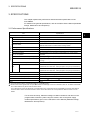
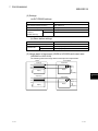
3.3 I/O Signal
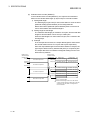
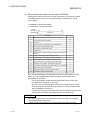
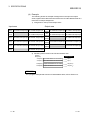
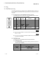
3.3.1 I/O signal list
The following I/O signal assignment is based on the case where the start I/O No. of
the QJ71PB92D is "0000" (installed to slot 0 of the main base unit).
Device X represents input signals from the QJ71PB92D to the QCPU.
Device Y represents output signals from the QCPU to the QJ71PB92D.
The following shows the I/O signals to/from the QCPU.
Signal direction: QJ71PB92D
Device No.
QCPU
Description
Signal direction: QCPU
Device No.
QJ71PB92D
Description
X00
Exchange start end signal
Y00
Exchange start request signal
X01
Communication trouble detection signal
Y01
Communication trouble detection signal reset
X02
Communication trouble area clear end signal
Y02
Communication trouble area clear request signal
Y03
Communication trouble area type selection signal
X04
Global control end signal
Use prohibited
Y04
Global control request signal
X05
Global control error end signal
Y05
……
X03
Use prohibited
Y0C
Dedicated instruction valid signal
Y0D
Restart request signal
Y0E
X0F
X10
Operation mode signal
Y10
X11
Operation mode change completion signal
Y11
X1A
X1B
X1D
X1E
X1F
Use prohibited
Operation mode change request signal
Y12
Use prohibited
Communication READY signal
Use prohibited
Module READY signal
Use prohibited
Watchdog timer error signal
… … … … … …
…
X12
X1C
Use prohibited
Y0B
…
… … … … …
X06
Use prohibited
Y1F
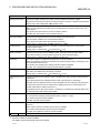
POINT
Do not output (turn ON) the "Use prohibited" signals.
Doing so may cause the programmable controller system malfunction.
3 - 12
3 - 12
3 SPECIFICATIONS
MELSEC-Q
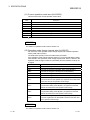
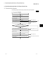
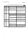
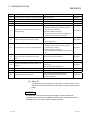
3.3.2 I/O signal detail description
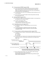
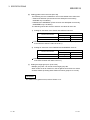
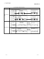
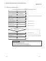
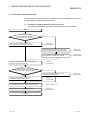
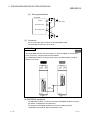
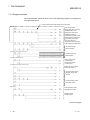
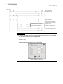
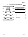
(1) Exchange start request signal (Y00), exchange start end signal
(X00)
(a) Turn ON the exchange start request signal (Y00) to start I/O data
exchange.
(b) When I/O data exchange is started after turning ON the exchange start
request signal (Y00), the exchange start end signal (X00) turns ON.
(c) The exchange start end signal (X00) turns OFF in any of the following
cases:
• When the exchange start request signal (Y00) is turned OFF
• When an error causing stop of I/O data exchange occurs
• When parameters are currently being written to the QJ71PB92D from
GX Configurator-DP
• When the operation mode of the QJ71PB92D has been changed
• When a communication error has occurred on a slave station. (Only
when the master parameter, "Error action flag" is checked)
Data exchange start request
Exchange start
request signal (Y00)
Maximum 200 ms
Data exchange start
completed
Exchange start
end signal (X00)
I/O data exchange
stopped
Exchanging I/O data
I/O data exchange
stopped
(d) Use these signals as interlock signals when reading/writing I/O data.
(e) Write the initial values of the output data to the buffer memory before
turning ON the exchange start request signal (Y00).
3 - 13
3 - 13
3 SPECIFICATIONS
MELSEC-Q
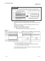
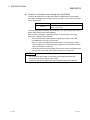
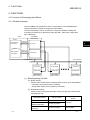
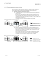
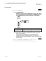
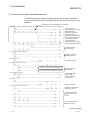
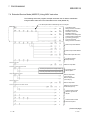
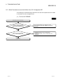
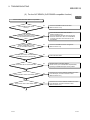
(2) Communication trouble detection signal reset (Y01),
communication trouble detection signal (X01)
(a) The communication trouble detection signal (X01) turns ON when a
communication failure is detected after the time preset in the trouble no
information time setting area (Un\G2084) has elapsed.
The following processing is performed at the same time that the
communication trouble detection signal (X01) turns ON:
• The RSP ERR. LED turns ON.
• The trouble information is stored in the communication trouble area
(Un\G2040 to Un\G2079).
• The expansion trouble information is stored in the expansion
communication trouble area (Un\G2096 to Un\G2110).
• The corresponding bit in the Slave status area (Un\G2112 to Un\G2116)
of the station that sent the trouble information turns ON.
(b) The communication trouble detection signal (X01) is turned off when the
communication trouble detection signal reset signal (Y01) is turned ON or
when communication failure is all resolved. At this time, the RSP ERR. LED
turns off.
(c) The communication trouble detection signal reset (Y01) is turned OFF after
it has been confirmed that the communication trouble detection signal (X01)
has been turned off.
(d) The following sequence is used.
Communication trouble detection signal reset (Y01)
Communication trouble detection signal (X01)
Reads standard and expansion communication
trouble information from buffer memory. *1
Trouble detection reset
Trouble
detection
MOV/FROM
instruction
1 Communication trouble area (Un\G2040 to Un\G2079)
Expansion communication trouble area (Un\G2096 to Un\G2110)
3 - 14
3 - 14
3 SPECIFICATIONS
MELSEC-Q
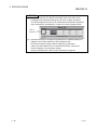
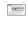
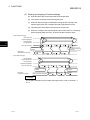
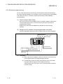
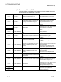
POINT
(1) While the communication trouble detection signal reset (Y01) is ON, another
communication failure may occur. In such cases, the QJ71PB92D detects a
communication trouble again. (The communication trouble detection signal
(X01) turns ON and the RSP ERR. LED lights up.)
To turn OFF the communication trouble detection signal (X01), switch the
communication trouble detection signal reset (Y01) from OFF to ON, or remove
the communication error cause.
Communication trouble 1
Communication trouble 2
Communication trouble detection signal reset (Y01)
Communication trouble detection signal (X01)
Even if Y01 is ON, a other communication trouble is detected.
When successive communication failures occur, turning ON the communication
trouble detection signal reset (Y01) may not turn OFF the communication
trouble detection signal (X01). In such a case, turn OFF the communication
trouble detection signal reset (Y01) and then ON again.
(2) When the communication trouble detection signal (X01) is turned OFF by the
communication trouble detection signal reset (Y01) while the target
communication failure remains, this failure is not detected again even if the
communication trouble detection signal reset (Y01) is turned OFF.
Communication trouble
Communication trouble detection signal reset (Y01)
Communication trouble detection signal (X01)
Current trouble is not detected
again by turning OFF Y01.
REMARK
The slave status area is automatically cleared when a communication failure is
removed.
Turning ON the communication trouble detection signal reset (Y01) does not clear
this area.
3 - 15
3 - 15
3 SPECIFICATIONS
MELSEC-Q
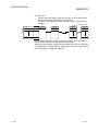
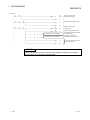
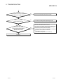
(3) Communication trouble area clear request signal (Y02),
communication trouble area clear end signal (X02)
(a) Turn ON the communication trouble area clear request signal (Y02) when
clearing the following information:
• Communication trouble area (Un\G2040 to Un\G2079)
• Expansion communication trouble area (Un\G2096 to Un\G2110)
(b) When the communication trouble area clear request signal (Y02) is turned
ON, and the processing at clear is completed, the communication trouble
area clear end signal (X02) turns ON.
(c) After the communication trouble area clear end signal (X02) has turned ON,
turn OFF the communication trouble area clear request signal (Y02).
(d) Taking corrective actions for the error and turning OFF the communication
trouble area clear request signal (Y02) turns OFF the communication
trouble area clear end signal (X02).
(e) A sequence like the one below is used.
Communication trouble area clear request signal (Y02)
Communication trouble area clear end signal (X02)
3 - 16
Clear request
Clear end
3 - 16
3 SPECIFICATIONS
MELSEC-Q
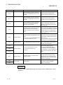
POINT
(1) While the communication trouble area clear request signal (Y02) is ON, another
communication failure may occur. In such cases, the QJ71PB92D detects a
communication trouble again. (Communication trouble information is stored to
the communication trouble area and the expansion communication trouble
area.)
To clear these areas, turn OFF the communication trouble area clear request
signal (Y02) and then ON again.
Communication trouble 1
Communication trouble 2
Communication trouble area
clear request signal (Y02)
Communication trouble area
(Un\G2040 to Un\G2079)
Expansion communication
trouble area (Un\G2096 to Un\G2110)
Info. of
trouble 1
Info. of
trouble 2
Even if Y02 is ON, another communication
trouble is detected.
When successive communication failures occur, turning ON the communication
trouble area clear request signal (Y02) may not clear the standard and
expansion communication trouble areas.
In such a case, turn OFF the communication trouble area clear request signal
(Y02) and then ON again.
(2) When communication trouble information is cleared by the communication
trouble area clear request signal (Y02) while the target communication failure
remains, the information of this failure is not stored again even if the
communication trouble area clear request signal (Y02) is turned OFF.
Communication trouble
Communication trouble area
clear request signal (Y02)
Communication trouble area
(Un\G2040 to Un\G2079)
Expansion communication
trouble area (Un\G2096 to Un\G2110)
3 - 17
Trouble
information
Trouble
information
Current trouble information is not stored
again by turning OFF Y02.
3 - 17
3 SPECIFICATIONS
MELSEC-Q
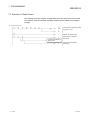
(4) Global control request signal (Y04), global control end signal
(X04)
(a) Turn ON the Global control request signal (Y04) when executing the global
control.
(b) When the Global control request signal (Y04) is turned ON, and global
control processing is completed, the Global control end signal (X04) turns
ON.
(c) After the Global control end signal (X04) has turned ON, turn OFF the
Global control request signal (Y04).
(d) Turning OFF the Global control request signal (Y04) turns OFF the Global
control end signal (X04).
(e) Turn ON the Global control request signal (Y04) while the exchange start
completed signal (X00) is ON.
If the Global control request signal (Y04) is turned ON with the exchange
start completed signal (X00) OFF, both of the Global control end signal
(X04) and Global control error end signal (X05) turn ON.
Exchange start
completed signal (X00)
Output data is written.
1
Writing of
output data
Global control request signal (Y04)
Global control end signal (X04)
1 Output area (Un\G960 to Un\G1919)
(5) Global control error end signal (X05)
(a) If the Global control request signal (Y04) is turned ON while the exchange
start completed signal (X00) is OFF, both the Global control end signal
(X04) and Global control error end signal (X05) turn ON.
(b) The ON status of the Global control error end signal (X05) means that the
global control has failed.
Remedy the cause of the error, and execute the global control again.
(c) The slave I/O is not held/deleted when the global control error end signal
(X05) is on.
(d) Turning OFF the Global control request signal (Y04) turns OFF the Global
control error end signal (X05).
Global control request signal (Y04)
Global control end signal (X04)
Global control error end signal (X05)
Global control request
Global control end
Global control error end
REMARK
For details on the global control, refer to Section 4.1.2.
3 - 18
3 - 18
3 SPECIFICATIONS
MELSEC-Q
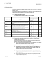
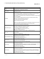
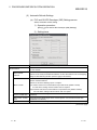
(6) Operation mode signal (X10)
Indicates whether the current operation mode is the parameter setting mode
(MODE 1) or not.
ON: Parameter setting mode (MODE 1)
OFF: Normal service mode (MODE 0), extended service mode (MODE E), selfdiagnosis mode (MODE 2), initialization mode of flash ROM
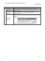
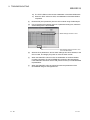
(7) Operation mode change request signal (Y11), operation mode
change completion signal (X11)
(a) Turn ON the Operation mode change request signal (Y11) when changing
the operation mode to the one set in the Operation mode change request
area (Un\G2255).
The operation mode can be changed without resetting the QCPU.
(b) Turning ON the Operation mode change request signal (Y11) clears the
information of the Operation mode change result area (Un\G2256).
(c) The Operation mode change completion signal (X11) turns ON when the
operation mode is changed, and the result of the change is stored to the
Operation mode change result area (Un\G2256).
(d) Make sure that 0H is stored in the Operation mode change result area
(Un\G2256), and turn OFF the Operation mode change request signal
(Y11).
(e) Turning OFF the Operation mode change request signal (Y11) turns OFF
the Operation mode change completion signal (X11).
Exchange start
request signal: Y00
Operation mode change
request signal: Y11
Operation mode change
completion signal: X11
Operation mode change
result area (Un\G2256)
Change result of operation mode
MOV/TO
instruction
Sets the operation mode
in the "operation mode
change request area".
MOV/FROM
instruction
Confirms the result in the
"operation mode change result
area" and "current operation mode".
IMPORTANT
When the operation mode change request signal (Y11) is on, do not turn off the
power or reset the QCPU during registration of the operation mode to the flash
ROM.
To do so may result in repair of the QJ71PB92D.
Turn the power off or reset the QCPU after the operation mode change
completion signal (X11) has turned on.
3 - 19
3 - 19
3 SPECIFICATIONS
MELSEC-Q
(8) Communication READY signal (X1B)
(a) The Communication READY signal (X1B) turns ON when the Module
READY signal (X1D) turns ON and I/O data exchange is ready to be
started. (The signal turns ON only in the Normal service mode (MODE 0)
and Extended service mode (MODE E).)
(b) The signal turns OFF when an error disabling I/O data exchange occurs on
the QJ71PB92D.
(c) Use the signal as an interlock signal for when turning ON the exchange
start request signal (Y00).
(9) Module READY signal (X1D)
(a) This signal turns ON when the QJ71PB92D is started up. (This signal turns
ON regardless of the operation mode.)
(b) It is OFF in the following cases.
• When the QJ71PB92D is not ready
• During execution of operation mode change
(10) Watchdog timer error signal (X1F)
(a) This signal turns ON when a watchdog timer error occurs on the
QJ71PB92D.
(b) The Watchdog timer error signal (X1F) does not turn OFF until:
• The programmable controller is turned OFF and back ON again
• The QCPU is reset.
(11) Communication trouble area type selection signal (Y03)
(a) This signal is used to select the communication trouble area type (ring type
or fixed type).
ON: Fixed type
OFF: Ring type
(b) This signal becomes valid when the exchange start (Exchange start request
signal (Y00) is ON) or communication trouble area clear request signal
(Y02) is ON.
Fixed type
Communication trouble area
type selection signal (Y03) Ring type
Exchange start end signal (X00)
or
Communication trouble area
clear request signal (Y02)
Communication trouble area type
Ring type (default)
Fixed type
Ring type
When the exchange start request signal (Y00) or communication
trouble area clear request signal (Y02) turns ON, selection of the
communication trouble area type selection signal (Y03) is enabled.
(c) When employing the fixed type, the communication trouble area type
selection signal (Y03) must be constantly ON.
For the ring type, the communication trouble area type selection signal
(Y03) must be constantly OFF.
3 - 20
3 - 20
3 SPECIFICATIONS
MELSEC-Q
(12) Dedicated instruction valid signal (Y0C)
(a) This signal is used when the dedicated instruction for separation prevention
is validated.
ON: Read/Write by dedicated instruction is validated.
OFF: Read/Write by dedicated instruction is invalidated.
(b) Keep the signal turned ON while the dedicated instruction is being used.
(c) When using the data separation prevention function (automatic refresh) by
the GX Configurator-DP, turn OFF the dedicated instruction valid signal
(Y0C).
(13) Restart request signal (Y0D)
(a) If the QJ71PB92D has gone down for some reason (the FAULT LED: ON,
the module READY signal (X1D): OFF), turning the Restart request signal
(Y0D) OFF, ON and OFF again restarts the QJ71PB92D.
(b) After the QJ71PB92D is restarted, the status is the same as after:
• The programmable controller is turned OFF and back ON again
• The QCPU is reset.
3 - 21
3 - 21
3 SPECIFICATIONS
MELSEC-Q
3.4 Buffer Memory List
3.4.1 Buffer memory/configuration
The configuration of the buffer memory used to receive and send data with the
QJ71PB92D and the programmable controller CPU is described below.
Buffer memory address
decimal (Hexadecimal)
0
(0H)
959
(3BFH)
960
(3C0H)
1919
(77FH)
1920
(780H)
2039
(7F7H)
2040
(7F8H)
Area name
Description
Input area
This is the area that stores the input data from the slave.
Output area
This is the area that stores the output data to the slave.
Address information area
This is the area that shows the station number of slave station and I/O data
length.
Communication trouble area
This is the area that shows the trouble information that occurred during
communication.
2079
(81FH)
2080
(820H)
Slave error information cancel area
This is the area that sets the data that masks the slave trouble information.
2081
(821H)
Global control area
This is the global control function hold/cancel selection area.
2082
(822H)
System area (Use prohibited)
2083
(823H)
2084
(824H)
Trouble no information time setting area
2085
(825H)
System area (Use prohibited)
2095
(82FH)
2096
(830H)
Expansion communication trouble area
2110
(83EH)
2111
(83FH)
System area (Use prohibited)
2112
(840H)
Slave status area
2116
(844H)
2117
(845H)
2127
(84FH)
2128
(850H)
System area (Use prohibited)
Input/Output start address area (Extended
service mode only)
⎯
This is used to set the time that does not inform the communication trouble
after the exchange start.
⎯
This area shows the expansion information of the trouble information which
is occurred during the communication.
⎯
This is the area that shows the status information of each slave.
⎯
This is the area that shows the addresses to start the input area and output
area of each slave.
2247
(8C7H)
2248
(8C8H)
2253
(8CDH)
2254
(8CEH)
Current operation mode area
This area indicates the operation mode of the QJ71PB92D when it has
started up.
2255
(8CFH)
Operation mode change request area
In this area, set the operation mode of the QJ71PB92D which you want to
choose.
2256
(8D0H)
Operation mode change result area
This area indicates the execution result of the operation mode change
request.
2257
(8D1H)
Local station number display area
Area in which the station number of the local station is stored.
2258
(8D2H)
Self-diagnosis status code area
Area in which the code indicating the status of the self-diagnosis during the
execution of the diagnosis is stored.
2259
(8D3H)
3775
(EBFH)
System area (Use prohibited)
System area (Use prohibited)
⎯
⎯
POINT
Do not write any data in the "system area (Use prohibited)" of the buffer memory.
If data is written to the "system area (Use prohibited)" , there is a risk that the
programmable controller system may malfunction.
3 - 22
3 - 22
3 SPECIFICATIONS
MELSEC-Q
3.4.2 Buffer memory detailed description
(1) INPUT area (Un\G0 to Un\G959)
Data input from slave stations are stored in this area.
The specifications of the input area differ depending on the operation mode of
the QJ71PB92D.
POINT
(1) Data are assigned to the input area in the order of GX Configurator-DP
parameter settings (in the order of station numbers).
The actual assignment order can be confirmed in the Address information
area (Un\G1920 to Un\G2039) or in Slave List of GX Configurator-DP.
Order of
assignment
(2) The buffer memory is reassigned if parameters are modified (deletion or
addition of some slave stations) in GX Configurator-DP.
Check the sequence program after modifying the parameters.
If there are slave stations to be connected in the future, set them as reserved
stations in the parameter setting.
Doing so eliminates the need to check the sequence program.
(3) The input area of the QJ71PB92D does not store input data of the slave
station that has become incapable of exchanging I/O data and whose bit in
the slave status area (Un\G2113 to Un\G2116) has turned ON.
For the slave station, the input area holds the data that were stored before
the failure of I/O data exchange.
3 - 23
3 - 23
3 SPECIFICATIONS
MELSEC-Q
(a) Normal service mode (MODE 0)
In the normal service mode (MODE 0), 60 stations are allocated to the
input area with 32 bytes (16 words) reserved for each station.
An unused input area for each slave station stores 00H.
1) Example
In the example shown below, the input data lengths for the first and the
second stations are set to 29 bytes and 32 bytes respectively.
Since the input data length for the first slave station is 29 bytes, 00H is
stored to the unused area (the upper byte of buffer memory address
14 (EH), and 15 (FH)).
Buffer memory
0(0H)
address decimal
(Hexadecimal)
15(FH)
(Upper byte)
(Lower byte)
1st module 2nd byte
1st module 1st byte
1st module 4th byte
1st module 3rd byte
b15
1st module input data
Buffer memory 0(0H)
address decimal
(Hexadecimal) 1(1H)
b0
16(10H)
1
2nd module input data
31(1FH)
14(EH)
1st module 29th byte
15(FH)
n th module input data
16(10H)
2nd module 2nd byte
2nd module 1st byte
17(11H)
2nd module 4th byte
2nd module 3rd byte
1
944(3B0H)
60th module input data
959(3BFH)
30(1EH) 2nd module 30th byte
2nd module 29th byte
31(1FH) 2nd module 32th byte
2nd module 31th byte
b0
b15
: Free area (00H)
1 Since the data area is fixed to 32 bytes,
all unused areas will become free.
3 - 24
3 - 24
3 SPECIFICATIONS
MELSEC-Q
(b) Extended service mode (MODE E)
In the extended service mode (MODE E), the input area is allocated based
on the variable data length (in byte units) for each slave station.
1) Setting data length
The data length (in byte units) for each slave station is set in the slave
parameter setting (Slave Modules) of GX Configurator-DP.
Note that this slave parameter (Slave Modules) does not have to be
set for slave stations with fixed data lengths.
2) Setting range for data length
The maximum data length per module is 244 bytes, and the total data
length for all slave station can be set up to 1920 bytes.
When the data length is an odd number of bytes, 00H is stored to the
final high byte.
3) Example
In the example shown below, the input data lengths for the first and the
second stations are set to 23 bytes and 7 bytes respectively.
Since the input data length for the first slave station is 23 bytes, the
upper byte of buffer memory address 11 (BH) is occupied by 00H.
The input data of the next station is assigned starting from the next
buffer memory address.
Buffer memory
address decimal
(Hexadecimal)
Buffer memory
address decimal
(Hexadecimal)
b15 (Upper byte)
0(0H)
1st module input data
11(BH)
(Lower byte)
b0
0(0H)
1st module 2nd byte
1st module 1st byte
1(1H)
1st module 4th byte
1st module 3rd byte
10(AH) 1st module 22th byte
1st module 21th byte
11(BH)
1st module 23th byte
12(CH)
2nd module input data
15(FH)
n th module input data
60th module input data
2nd module 2nd byte
2nd module 1st byte
13(DH) 2nd module 4th byte
2nd module 3rd byte
14(EH) 2nd module 6th byte
2nd module 5th byte
15(FH)
2nd module 7th byte
12(CH)
b0
b15
: Free area (00H)
2 When the data length is set to an odd number
of bytes, the last upper byte becomes a free area
and data for the next station is assigned from
the next address.
3 - 25
3 - 25
2
3 SPECIFICATIONS
MELSEC-Q
POINT
If a slave station with no input data is assigned, its space in the input area is taken
over by the next station with input data, resulting in the figure shown below.
Each slave station setting
1st station Input data: Present
2nd station Input data: None
3rd station Input data: Present
4th station Input data: Present (Data length: 0)
5th station Input data: Present
3 - 26
Input area assignment results in QJ71PB92D
0 (0H)
Input data of 1st station
Input data of 3rd station
Input data of 5th station
No area is assigned for the 2nd and
4th stations that have no input data.
3 - 26
3 SPECIFICATIONS
MELSEC-Q
(2) OUTPUT area (Un\G960 to Un\G1919)
Data output from slave stations are stored in this area.
The specifications of the output area differ depending on the operation mode of
the QJ71PB92D.
POINT
(1) Data are assigned to the output area in the order of GX Configurator-DP
parameter settings (in the order of station numbers).
The actual assignment order can be confirmed in the Address information
area (Un\G1920 to Un\G2039) or in Slave List of GX Configurator-DP.
Order of
assignment
(2) The buffer memory is reassigned if parameters are modified (deletion or
addition of some slave stations) in GX Configurator-DP.
Check the sequence program after modifying the parameters.
If there are slave stations to be connected in the future, set them as
reserved stations in the parameter setting.
Doing so eliminates the need to check the sequence program.
3 - 27
3 - 27
3 SPECIFICATIONS
MELSEC-Q
(a) Normal service mode (MODE 0)
In the normal service mode (MODE 0), 60 stations are allocated to the
output area with 32 bytes (16 words) reserved for each station.
Set 00H in an unused output area assigned to each slave station.
1) Example
In the example shown below, the output data lengths for the first and
the second stations are set to 1 byte and 3 bytes respectively.
Since the output data length for the first slave station is 1 byte, set 00H
in the unused area (the upper byte of buffer memory address 960
(3C0H), and 961 (3C1H) to 975 (3CFH)).
Buffer memory
address decimal
(Hexadecimal) b15
Buffer memory
address decimal
(Hexadecimal)
960(3C0H)
(Upper byte)
960(3C0H)
1st module output data
975(3CFH)
(Lower byte)
b0
1st module 1st byte
961(3C1H)
976(3D0H)
1
2nd module output data
991(3DFH)
974(3CEH)
975(3CFH)
n th module output data
976(3D0H)
2nd module 2nd byte
977(3D1H)
2nd module 1st byte
2nd module 3rd byte
1
1904(770H)
60th module output data
1919(77FH)
991(3DFH)
b0
b15
: Free area (00H)
1 Since the data area is fixed to 32 bytes,
all unused areas will become free.
3 - 28
3 - 28
3 SPECIFICATIONS
MELSEC-Q
(b) Extended service mode (MODE E)
In the extended service mode (MODE E), the output area is allocated
based on the variable data length (in byte units) for each slave station.
1) Setting data length
The data length (in byte units) for each slave station is set in the slave
parameter setting (Slave Modules) of GX Configurator-DP.
Note that this slave parameter (Slave Modules) does not have to be
set for slave stations with fixed data lengths.
2) Setting range for data length
The maximum data length per module is 244 bytes, and the total data
length for all slave station can be set up to 1920 bytes.
When the data length is an odd number of bytes, 00H is stored to the
final high byte.
3) Example
In the example shown below, the output data lengths for the first and
the second stations are set to 19 bytes and 5 bytes respectively.
Since the output data length for the first slave station is 19 bytes, the
upper byte of buffer memory address 969 (3C9H) is occupied by 00H.
The output data of the next station is assigned starting from the next
buffer memory address.
Buffer memory
address decimal
(Hexadecimal)
Buffer memory
address decimal
(Hexadecimal) b15
960(3C0H)
1st module output data
969(3C9H)
(Upper byte)
(Lower byte)
b0
960(3C0H)
1st module 2nd byte
1st module 1st byte
961(3C1H)
1st module 4th byte
1st module 3rd byte
968(3C8H)
1st module 18th byte
1st module 17th byte
970(3CAH)
2nd module output data
972(3CC H)
1st module 19th byte
969(3C9H)
n th module output data
970(3CAH)
2nd module 2nd byte
2nd module 1st byte
971(3CBH)
2nd module 4th byte
2nd module 3rd byte
972(3CCH)
60th module output data
2nd module 5th byte
b0
b15
: Free area (00H)
2 When the data length is set to an odd number
of bytes, the last upper byte becomes a free area
and data for the next station is assigned from
the next address.
3 - 29
3 - 29
2
3 SPECIFICATIONS
MELSEC-Q
POINT
If a slave station with no output data is assigned, its space in the output area is
taken over by the next station with output data, resulting in the figure shown below.
Each slave station setting
1st station Output data: Present
Input area assignment results in QJ71PB92D
960 (3C0H)
Output data of 1st station
2nd station Output data: None
Output data of 3rd station
3rd station Output data: Present
Output data of 5th station
4th station Output data: Present (Data length: 0)
5th station Output data: Present
No area is assigned for the 2nd and
4th stations that have no output data.
(3) Address information area (Un\G1920 to Un\G2039)
The station number and I/O data length of each slave station are stored in this
area.
Information of 60 modules is stored in the Address information area in the
same order for each module.
Information for reserved stations is also stored.
(a) Address information area configuration
The address information area configuration is shown below.
Buffer memory
Address
DEC (HEX)
b15
The station number of the 1st module is stored. (Initial value: FFFFH)
1920(780H)
Station number of 1st module
1921(781H)
I/O data length of 1st module
1922(782H)
Station number of 2nd module
1923(783H)
I/O data length of 2nd module
to
2038(7F6H)
b0
1920(780H) 0000H to 007DH (0 to 125): station number
FFFFH: No station number assigned
The input data length of the 1st The output data length of the 1st
module is stored. (Initial value: module is stored. (Initial value:
FFH) *1
FFH) *1
1921(781H)
Station number of 60th module
b8 b7
: Input data
length
(unit: byte)
FFH: Input data not assigned
00H to F4H
00H to F4H
: Output data
length
(unit: byte)
FFH: Output data not assigned
2039(7F7H) I/O data length of 60th module
1 The difference between 00H and FFH is as follows:
00H: The set data length is 0 although input or output data is assigned.
FFH: Input or output data are not assigned.
The QJ71PB92D assigns the input and output areas according to the information
stored in the address information area.
3 - 30
3 - 30
3 SPECIFICATIONS
MELSEC-Q
Example: At extended service mode (MODE E)
CPU module
QJ71PB92D
PROFIBUS-DP
network
Bus terminator
Slave
Slave
Station number : 5
Input data length : 3 byte
Output data length : 0 byte
Station number : 10
Input data length : 7 byte
Output data length : 5 byte
IN P U T
Buffer memory
address decimal
(Hexadecimal) b15
INPUT/OUTPUT area
b0
Buffer memory
address decimal
(Hexadecimal) b15
0(0H)
1st module 2nd input byte 1st module1st input byte
1920(780H)
1(1H)
1st module 3rd input byte
1921(781H)
2(2H)
2nd module 2nd input byte 2nd module 1st input byte
1922(782H)
3(3H)
2nd module 4th input byte 2nd module 3rd input byte
1923(783H)
Address information area
b0
5
3
1
0
2
3
10
7
5
4(4H) 2nd module 6th input byte 2nd module 5th input byte
5(5H)
2nd module 7th input byte
1 Station number (FFFFH if not assigned)
2 Input data length (FFH if not assigned)
3 Output data length (FFH if not assigned)
1, 2 and 3 are also set in a reserved station.
6(6H)
959(3BFH)
960(3C0H) 2nd module 2nd output byte 2nd module 1st output byte
OUTPUT
961(3C1H) 2nd module 4th output byte 2nd module 3rd output byte
962(3C2H)
4
2nd module 5th output byte
963(3C3H)
: Vacant area
(The free areas in the INPUT area
are initialized with [00H].)
1919(77FH)
4 Since output from the first station has a data length of 0,
no area is allocated in the OUTPUT area.
3 - 31
3 - 31
3 SPECIFICATIONS
MELSEC-Q
POINT
(1) Data are assigned to the address information area in the order of GX
Configurator-DP parameter settings (in the order of station numbers).
The actual assignment order can be confirmed in the Address information
area (Un\G1920 to Un\G2039) or in Slave List of GX Configurator-DP.
Order of
assignment
(2) The buffer memory is reassigned if parameters are modified (deletion or
addition of some slave stations) in GX Configurator-DP.
Check the sequence program after modifying the parameters.
If there are slave stations to be connected in the future, set them as
reserved stations in the parameter setting.
Doing so eliminates the need to check the sequence program.
3 - 32
3 - 32
3 SPECIFICATIONS
MELSEC-Q
(4) Communication trouble area (Un\G2040 to Un\G2079)
When some kind of trouble occurs during communication the QJ71PB92D
stores the contents of the trouble in this area.
(a) Communication trouble area configuration
As shown in the following diagram, a total of 8 pieces of trouble
information that consist of the trouble code, detailed data length, and
detailed data can be stored.
Buffer memory
address decimal
(Hexadecimal)
Buffer memory
address decimal
(Hexadecimal)
2040(7F8H)
2044(7FCH)
2045(7FDH)
2049(801H)
2050(802H)
2054(806H)
2075(81BH)
2079(81FH)
Trouble information area 1
Trouble information area 2
2040(7F8H)
Error code
2041(7F9H)
2042(7FAH)
Detailed data length (0 to 3)
2043(7FBH)
2044(7FCH)
Detailed data 1
Detailed data 2
Detailed data 3
Trouble information area 3
Trouble information area 8
REMARK
For error codes and detailed data, refer to Section 9.4.1.
How to store the trouble information can be selected from the ring type and
the fixed type by turning ON or OFF the communication trouble area type
selection signal (Y03).
1) Ring type
Trouble information is stored in order from the head area of the
communication trouble area.
The latest trouble information is always stored in the head area of the
communication trouble area.
Ring type
: The latest data
Trouble
information area 1
Trouble
information area 2
Trouble
information area 8
3 - 33
Data 1
Data 2
Data 8
Data 9
Data 1
Data 7
Data 8
Data 1
Data 2
3 - 33
3 SPECIFICATIONS
MELSEC-Q
Fixed type
2) Fixed type
Trouble information data in areas 2 to 8 (data 1 to 7) are fixed even if
the 9th or later trouble information is generated.
The data of the 9th trouble or later is stored in area 1. (Area 1 only is
updated.)
Trouble
information area 1
Trouble
information area 2
Trouble
information area 8
Data 1
: The latest data
Data 9
Data 2
Data 8
Data 1
Data 7
Data 7
Data 1
Data 1
All the trouble information in either type can be cleared by turning ON the
communication trouble area clear request signal (Y02).
When the communication trouble detection signal reset (Y01) is turned ON,
the communication trouble detection signal (X01) turns OFF with the data in
the communication trouble area retained.
3 - 34
3 - 34
3 SPECIFICATIONS
MELSEC-Q
(5) Expansion communication trouble area (Un\G2096 to Un\G2110)
This area shows the latest expansion trouble information for only one of the
latest expansion trouble information in the error code 0200H error information
stored in buffer memory 2040 (7F8H) to 2079 (81FH) communication error area
(Refer to Section 3.4.2 (4)).
For details of the expansion trouble information, refer to the manual of the slave
station.
Communication trouble area
(When fixed buffer is selected.)
Area 1
Data 10
Area 2
Data 7
No error code=0200H
expansion trouble
information (trouble
information bit 11 = 0)
Buffer memory
address decimal
(Hexadecimal)
Expansion trouble information area
2096 (830H)
2097 (831H)
Data 6
(Latest data)
Data 5
There is error code=
0200H expansion
trouble information
(trouble information
bit 11 = 1)
Data 4
Data 3
Data 2
Area 8
2110 (83EH)
Data 1
(a) Buffer Memory 2096 (830H)
The latest expansion communication trouble information length stored from
buffer memory 2098 (832H) is stored as a byte length unit.
Buffer memory
address decimal Expansion trouble information area
(Hexadecimal)
9096 (830H)
21
9097 (831H)
9098 (832H)
21 bytes = 10 words + 1 byte
2110 (83EH)
3 - 35
3 - 35
3 SPECIFICATIONS
MELSEC-Q
(b) Buffer memory 2097 (831H)
Only bit 7 is valid.
Other bit is fixed in 0.
Bit 7 is turned on when the slave sends expansion trouble information that
is 27 bytes or more.
MSB
Bit position
15
LSB
14
13
12
11
10
9
8
7
6
5
4
0 fixed
3
2
1
0
0 fixed
(c) Buffer memory 2098 (832 H) to 2110 (83EH)
The following informations are stored in this area:
Device related trouble information
This area stores the slave station inherent self-diagnostic information
that is not set by the PROFIBUS-DP standards.
Identifier related trouble information
For module type slave stations, whether or not a module error has
occurred is stored as bit information.
Channel related trouble information
For module type slave station, this stores the, error information of all
modules outputting an error.
1) Device Related trouble information
This stores the slave module inherent trouble information that is not
set by the PROFIBUS-DP standards. The device related trouble can
be divided by header and trouble information. This area stores a 2 bit
value that is the device related trouble information in the header,
including the header (1 byte), and the device related trouble
information for this area.
Buffer memory
address decimal
(Hexadecimal)
Header:
2098 (832H)
2099 (833H)
(2nd byte)
(4th byte)
Header
(1st byte)
Bit position
MSB
7
LSB
6
5
4
3
2
1
0
(3rd byte)
Device area length 2 to 63 in byte units
Bits 6 and 7 are set to 00.
3 - 36
3 - 36
3 SPECIFICATIONS
MELSEC-Q
2) Identifier related trouble information
For module type slave stations, this stores as bit information whether
or not a module is outputting an error. The identifier related trouble
information can be divided into header and trouble information. This
area stores a 2 bit value that is the identifier related trouble
information in the header, including the header (1 byte), and the
device related trouble information for this area.
Buffer memory
(End of device related trouble
information area)
Header:
Header
(1st byte)
(2nd byte)
(4th byte)
Bit position
MSB
7
LSB
6
5
4
3
2
1
0
(3rd byte)
Identifier area length 2 to 63 in byte units
Bits 6 and 7 are set as 01.
MSB
Bit position:
2nd byte
7
3rd byte
15
LSB
6
5
4
3
2
1
0
When this bit is 1, the 0th module has an error.
When this bit is 1, the 7th module has an error.
3 - 37
14
13
12
11
10
9
8
3 - 37
3 SPECIFICATIONS
MELSEC-Q
3) Channel related trouble information
When a module type slave station, this area stores the trouble
information for each module that is outputting an error. This area does
not have a header and stores this information at the end of the
identifier related trouble information. Each channel trouble information
consists of an identifier No., channel No., and error type of 3 bytes.
(End of identifier area)
Buffer memory
1st byte: Identifier No.
(2nd byte)
channel No.1
(1st byte)
identifier No.1
(4th byte)
identifier No.2
(3rd byte)
trouble type 1
(6th byte)
trouble type 2
(5th byte)
channel No.2
LSB
MSB
7
Bit position
6
5
4
3
2
1
0
Identifier Nos. 0 to 63
bits 6 and 7 are set to 10.
2nd byte: Channel No.
LSB
MSB
Bit position
7
6
5
4
3
2
1
0
Input/output
00 = Reserved
01 = Input
10 = Output
11 = Input/output
Channel number 0 to 63
3rd byte: Trouble type
LSB
MSB
Bit position
7
6
5
Channel type
000 = Reserved
001 = Bit
010 = 2 bit
011 = 4 bit
100 = byte
101 = Word
110 = 2 words
111 = Reserved
3 - 38
4
3
2
1
0
Error type:
0 Reserved
1 Short circuit
2 Voltage too low
3 Voltage too high
4 Overload
5 Temperature too high
6 Disconnected wire
7 Upper limit exceeded
8 Lower limit exceeded
9 Error
10 Reserved
15 Reserved
16 Manufacturer
31 Manufacturer
3 - 38
3 SPECIFICATIONS
MELSEC-Q
4) Identifier No., channel No.
The slave identifier No. and channel No. are discussed below.
The identifier No. is the No. that is attached from the header of each
slave module.
Each module can have multiple channels.
Refer to the each slave specifications regarding to the channel
numbering method.
Slave
16 point
DI
byte
2 channels
32 point
DO
byte
4 channels
32 point
DO
2 words
1 channels
PROFIBUS-DP
network
Slot
No.
Identifier No.
Channel No.
3 - 39
0
0
0,1
1
1
0,1,2,3
2
2
0
3 - 39
3 SPECIFICATIONS
MELSEC-Q
(d) Example expansion communication trouble area
Buffer memory
address decimal
(Hexadecimal)
2 bits
Expansion communication trouble information length (byte length)
2096(830H)
00 Header (length 4)
2098(832H)
0
01
01
01 Header (length 4)
0
01
Device
: Vendor independent trouble information
Identifier
0
00
00
01
10
00
00
Identifier Nos. 0 and 2 have trouble information.
00
10
00
00
10
10
00
01
00
11
00
01
11
10
00
00
00
Channel
10
Identifier No.0 and
channel No. (slot) 1 correspond,
channel type: byte, error: overload.
Identifier No.2 and
channel No. (Slot) 0 correspond,
channel type: 2 words, error: exceeds high limit value
Slave
16 point
DI
byte
2 channels
32 point
32 point
DO
DO
byte
2 word
4 channels 1 channels
PROFIBUS-DP
network
Slot
No.
Identifier No.
Channel No.
3 - 40
0
0
0,1
1
1
0,1,2,3
2
2
0
3 - 40
3 SPECIFICATIONS
MELSEC-Q
(6) Slave trouble information cancel area (Un\G2080)
Setting some values to this area can mask (invalidate) any data of the trouble
information that is sent from a slave station during communication. (Initial
value: 02B9H)
0: Validates the trouble information.
1: Invalidates the trouble information.
Address
DEC (HEX) b15
2080(820 H)
to
b0
See below.
Description
bit
Initial value
b0
Parameter transmission request from a slave station.
1
b1
Trouble information read request.
0
b2
Fixed to 0.
0
b3
The slave station is monitored by the watchdog timer.
1
b4
Slave station entered FREEZE mode.
1
b5
Slave station entered SYNC mode.
1
b6
0 (Reserved).
0
b7
Excluded from I/O data exchange according to the parameter
settings.
1
b8
Unable to exchange I/O data with slave station.
0
b9
The slave station is not ready to exchange I/O data.
1
b10
The parameter (No. of I/O bytes) received from the
master station does not match that of the slave station.
0
b11
Expansion communication trouble information exists.
0
b12
The function requested by the master station is not supported.
0
b13
Illegal response from slave station.
0
b14
Illegal parameter(s) sent from the master station.
0
b15
Controlled by another master station.
0
Even if trouble information corresponding to each bit is generated on a slave
station, it is not recognized as trouble information, and the status of the
QJ71PB92D is as follows:
• The communication trouble detection signal (X01) does not turn ON.
• The RSP ERR. LED does not turn ON.
• No error code and detailed data is stored in the communication trouble
area (Un\G2040 to Un\G2079) and/or expansion communication trouble
area (Un\G2096 to Un\G2110).
• The bit corresponding to the station that sent the trouble information does
not turn ON in the Slave status area (Un\G2112 to Un\G2116).
POINT
Set values into the slave error information cancel area when the exchange
start request signal (Y00) is OFF.
Values set with the exchange start request signal (Y00) ON are ignored.
3 - 41
3 - 41
3 SPECIFICATIONS
MELSEC-Q
(7) Global control area (Un\G2081)
(a) Set the global control function to be executed.
Specify the global control service to be sent by bits b5 to b2 in the Global
control area, and set the target group No. by bits b15 to b8. (Initial value:
0000H)
0: Not execute
1: Execute
Address
DEC(HEX) b15
2081(821H)
Description
bit
3 - 42
to
b0
See below.
Initial value Reference Section
b0
Unused (Fixed to 0)
0
b1
Unused (Fixed to 0)
0
b2
UNFREEZE (Retention of the actual input data is
disabled.)
0
b3
FREEZE (Actual input data is held and read.)
0
b4
UNSYNC (Retention of the actual input data is
disabled.)
0
b5
SYNC (Actual output data is written and held.)
0
b6
Unused (Fixed to 0)
0
Refer to (b)
b7
Unused (Fixed to 0)
0
b8
Executed on slave stations in group 1
0
b9
Executed on slave stations in group 2
0
b10
Executed on slave stations in group 3
0
b11
Executed on slave stations in group 4
0
b12
Executed on slave stations in group 5
0
b13
Executed on slave stations in group 6
0
b14
Executed on slave stations in group 7
0
b15
Executed on slave stations in group 8
0
See (b).
Refer to (c)
3 - 42
3 SPECIFICATIONS
MELSEC-Q
(b) Setting global control services (b5 to b2)
The following service combinations are not executable at the same time.
• SYNC and UNSYNC (If both services are attempted concurrently,
UNSYNC only is enabled.)
• FREEZE and UNFREEZE (If both services are attempted concurrently,
UNFREEZE only is enabled.)
The following shows the services and their set values for b5 to b2.
1) Setting for execution of the SYNC and UNSYNC services
Service to be Executed
SYNC
UNSYNC
Set Value
b5
b4
1
0
1
0*
1
1 When 1 is set to this bit, it is handled as an invalid value. (The operation
is the same as when the value is set to 0.)
2) Setting for execution of the FREEZE and UNFREEZE services
Service to be Executed
FREEZE
UNFREEZE
Set Value
b3
b2
1
0
1
0*
1
1 When 1 is set to this bit, it is handled as an invalid value. (The operation
is the same as when the value is set to 0.)
(c) Setting the target group No. (b15 to b8)
Multiple group Nos. can be set for the target group No.
When 0s are set to all of b8 to b15, the set global control service is sent to
all slave stations (including slave stations for which group No. is not set).
REMARK
For details on the global control, refer to Section 4.1.2.
3 - 43
3 - 43
3 SPECIFICATIONS
MELSEC-Q
(8) Trouble no information time setting area (Un\G2084)
The time during which no trouble information is notified after communication
start (after exchange start end signal (X00) turns ON) is set in this area. (Initial
value: 20 seconds)
Set Value
0 to 65535
Description
Set the time during which trouble information is not
notified. (Unit: seconds)
This setting prevents temporary error detection. (e.g. when turning ON a slave
station after turning ON the QJ71PB92D)
When trouble information is generated within the time duration set by this
setting, the conditions are as follows:
• The communication trouble detection signal (X01) does not turn ON.
• The RSP ERR. LED does not turn ON.
• No error code and detailed data is stored in the communication trouble
area (Un\G2040 to Un\G2079) and/or expansion communication trouble
area (Un\G2096 to Un\G2110).
• The bit corresponding to the station that sent the trouble information does
not turn ON in the Slave status area (Un\G2112 to Un\G2116).
POINT
Set a value into the trouble no information time setting area when the
exchange start request signal (Y00) is OFF.
Values set with the exchange start request signal (Y00) ON are ignored.
3 - 44
3 - 44
3 SPECIFICATIONS
MELSEC-Q
(9) Slave status area (Un\G2112 to Un\G2116)
This is the area that stores the status of each slave station.
The following figure shows the configuration:
Communication
status area
for all stations
Communication
status area for
individual stations
Buffer memory
address decimal
(Hexadecimal)
b15
b0
2112(840H) Communication status (all stations)
2113(841H)
Communication status
2114(842H)
(1st module to 60th module)
2115(843H)
2116(844H)
b15
b0
Indicates the communication status for all
stations by a bit.
0: Normal in all stations
1: Faulty station exists
b15
b0
(Fixed at 0)
Indicates the communication status of each of the individual
stations by a bit. (Reserve station and not set station are treated
as normal station)
0: Normal
1. Data link error occurred
b15
b0
1st module to 16th module
17th module to 32th module
33th module to 48th module
49th module to 60th module
Communication status
for all stations
b15 (Fixed at 0)
b0
The communication status of each slave
station under communication is set up.
This area is operated when either the normal
service mode (MODE 0) or extended service
mode (MODE E) is set up.
POINT
(1) Data are assigned to the slave station area in the order of GX ConfiguratorDP parameter settings (in the order of station numbers).
The actual assignment order can be confirmed in the Address information
area (Un\G1920 to Un\G2039) or in Slave List of GX Configurator-DP.
Order of
assignment
(2) The buffer memory is reassigned if parameters are modified (deletion or
addition of some slave stations) in GX Configurator-DP.
Check the sequence program after modifying the parameters.
If there are slave stations to be connected in the future, set them as reserved
stations in the parameter setting.
Doing so eliminates the need to check the sequence program.
3 - 45
3 - 45
3 SPECIFICATIONS
MELSEC-Q
(10) Input/Output start address area (Extended service mode (MODE
E) only)
(Un\G2128 to Un\G2247)
When the operation mode is extended service mode (MODE E), the start
address (buffer memory address) for each slave station I/O data is stored in this
area.
Creating a sequence program using this area allows address specification for the
input and output areas without considering the number of I/O points for each
slave station. (Refer to Section 7.3.)
In the normal service mode (MODE 0), 0s are stored in all areas.
(a) Configuration of I/O start address area
In this area, input data and output data of 60 stations are stored in the
same order.
Address
DEC (HEX)
b15
2128(850H) Input start address of 1st module
INPUT
2129(851H) Input start address of 2nd module
b0
The start address (buffer memory address) of the
input of the 1st module is stored. (Initial value: FFFFH)
2128(850H)
0 to 959 (0 H to 3BFH) : Input start address
FFFFH
: Input not assigned
2187(88BH) Input start address of 60th module
b15
2188(88CH) Output start address of 1st module
OUTPUT
2189(88DH) Output start address of 2nd module
b0
The start address (buffer memory address) of the
output of the 1st module is stored. (Initial value: FFFFH)
2188(88CH)
960 to 1919 (3C0 H to 77FH ) : Output start address
FFFF H
: Output not assigned
2247(8C7H) Output start address of 60th module
(b) Setup timing
The input start address and the output start address are stored when the
module is started up.
(c) Start address
The start address is set in 1 word units for both input and output.
The start address are stored in the input area or output area, starting from
the head.
3 - 46
3 - 46
3 SPECIFICATIONS
MELSEC-Q
POINT
(1) Data are assigned to the I/O start address ares in the order of GX
Configurator-DP parameter settings (in the order of station numbers).
The actual assignment order can be confirmed in the Address information
area (Un\G1920 to Un\G2039) or in Slave List of GX Configurator-DP.
Order of
assignment
(2) The buffer memory is reassigned if parameters are modified (deletion or
addition of some slave stations) in GX Configurator-DP.
Check the sequence program after modifying the parameters.
If there are slave stations to be connected in the future, set them as reserved
stations in the parameter setting.
Doing so eliminates the need to check the sequence program.
3 - 47
3 - 47
3 SPECIFICATIONS
MELSEC-Q
(d) Example
The following shows an example of assignment in the input and output
areas, together with values that are stored in the I/O start address area as a
result of the example assignment.
1) Assignment in the input and output areas
Input area
Output area
0(0H) 1st module 2nd input byte 1st module 1st input byte
960
1st module 2nd output byte 1st module 1st output byte
(3C0H)
1(1H)
961
1st module 4th output byte 1st module 3rd output byte
(3C1H)
1st module 3rd input byte
2(2H) 2nd module 2nd input byte 2nd module 1st input byte
962
(3C2H)
3(3H) 2nd module 4th input byte 2nd module 3rd input byte
963
2nd module 2nd output byte 2nd module 1st output byte
(3C3H)
4(4H) 2nd module 6th input byte 2nd module 5th input byte
964
(3C4H)
5(5H)
1st module 5th output byte
2nd module 3rd output byte
2nd module 7th input byte
2) Resulting values stored in the I/O start address area
Address
DEC(HEX)
Values stored
2128(850H) Input start address for 1st module
0(0H)
2129(851H) Input start address for 2nd module
2(2H)
2188(88CH) Output start address for 1st module
960(3C0H)
2189(88DH) Output start address for 2nd module
963(3C3H)
REMARK
For a program example that uses the I/O start address area, refer to Section 7.3.
3 - 48
3 - 48
3 SPECIFICATIONS
MELSEC-Q
(11) Current operation mode area (Un\G2254)
This area stores the current operation mode value.
Stored
Value
Description
0000H
Normal service mode (MODE 0)
0001H
Parameter setting mode (MODE 1)
0002H
Self-diagnosis mode (MODE 2)
0009H
Flash ROM initialization mode
000EH
Extended service mode (MODE E)
0100H
Normal service mode (MODE 0)*
0101H
Parameter setting mode (MODE 1)*
010EH
Extended service mode (MODE E)*
1
1
1
1 Operation mode currently stored to flash ROM.
REMARK
For details on operation mode, refer to Section 4.2.
(12) Operation mode change request area (Un\G2255)
For execution of the operation mode change request, set a desired operation
mode. (Initial value: FFFEH)
The initial value (FFFEH) is used for malfunction prevention.
If the Operation mode change request signal (Y11) is turned ON with the initial
value stored in the Operation mode change request area, 0001H is stored in the
Operation mode change result area (Un\G2256) and the operation mode is not
changed.
Setting value
Description
0000H
The mode is changed to normal service mode (MODE 0).
0001H
The mode is changed to parameter setting mode (MODE 1).
0002H
The mode is changed to self-diagnosis mode (MODE 2).
0009H
The mode is changed to flash ROM initialization mode.
000EH
The mode is changed to extended service mode (MODE E).
The mode is changed to normal service mode (MODE 0).
0100H
The normal service mode (MODE 0) is registered to the flash ROM
at the same time as the operation mode change.
The mode is changed to parameter setting mode (MODE 1).
0101H
The parameter setting mode (MODE 1) is registered to the flash
ROM at the same time as the operation mode change.
The mode is changed to extended service mode (MODE E).
010EH
The parameter setting mode (MODE 1) is registered to the flash
ROM at the same time as the operation mode change.
The mode is changed to parameter setting mode (MODE 1).
FFFFH
The mode registered to the flash ROM is deleted at the same time
as the operation mode change.
REMARK
For details on operation mode, refer to Section 4.2.
3 - 49
3 - 49
3 SPECIFICATIONS
MELSEC-Q
(13) Operation mode change result area (Un\G2256)
This area stores the execution result of the operation mode change request.
0: Normal completion.
1: Abnormal completion. (A mode change request of the unauthorized
value was given.)
On abnormal completion, the QJ71PB92D does not change the operation
mode. It maintains the same operation mode as before the change request was
given.
(14) Local station number display area (Un\G2257)
Used to store the number of the local station.
The storage area is 0 to 125.
(15) Self-diagnosis status code area (Un\G2258)
The self-diagnosis test details or test result is stored in this area.
For details on the self-diagnosis test, refer to Section 5.4.
3 - 50
3 - 50
4 FUNCTIONS
MELSEC-Q
4. FUNCTIONS
4.1 Functions for Exchanging with Slaves
4.1.1 I/O data exchange
The QJ71PB92D can operate as a class 1 master station on the PROFIBUS-DP
system and perform I/O data exchange with slave stations.
Up to 60 slave stations can be connected to a single QJ71PB92D, enabling the
exchange of I/O data up to 3840 bytes (Input data: Max. 1920 bytes, Output data:
Max.1920 bytes).
QCPU
QJ71PB92D
Buffer memory
Device
Input data from
slave station
Reading of
input data
4
Input area
Device
Output data to
slave station
Writing of
output data
Output area
Bus terminator
Bus terminator
Input data
No input data
Input data
Output data
Output data
No output data
Slave station
(Station number 1)
Slave station
(Station number 2)
Slave station
(Station number 60)
(1) Reading/writing I/O data
(a) Buffer memory
Read or write I/O data from the following buffer memory in the QJ71PB92D:
• Input data: Input area (Un\G0 to Un\G959)
• Output data: Output area (Un\G960 to Un\G1919)
(b) Read/write methods
Read or write I/O data (from the buffer memory) to devices in QCPU by the
following methods.
Read/Write Methods
Automatic refresh
Dedicated instructions
(BBLKRD, BBLKWR)
MOV or FROM/TO
instructions
4-1
Setting Location
Separation prevention
function
GX Configurator-DP
Sequence program
Sequence program
Available
Not available
4-1
4 FUNCTIONS
MELSEC-Q
(2) Starting and stopping I/O data exchange
(a) Write the initial value of the output data to the Output area.
(b) Turn ON the exchange start request signal (Y00).
(c) When I/O data exchange is started after turning ON the exchange start
request signal (Y00), the exchange start end signal (X00) turns ON.
(d) Input data from slave stations are stored in the Input area.
(e) When the exchange start request signal (Y00) is turned OFF, the exchange
start end signal (X00) turns OFF, and then I/O data exchange stops.
[Output data exchange]
Exchange start
request signal(Y00)
Exchange start
end signal(X00)
4
Bus cycle time (Bc)
Bc
Bc
Bc
I/O data exchange
started
output area
(Un\G960 to Un\G1919)
I/O data exchange
stopped
Output data at
Bc
(Initial
value)
Output data
at Bc
Output data
at Bc
Output data
at Bc
[Input data exchange]
Exchange start
request signal(Y00)
Exchange start
completed signal(X00)
Bus cycle time (Bc)
Bc
Bc
Bc
I/O data exchange
stopped
I/O data exchange
started
Input area
(Un\G0 to Un\G959)
Data of previous exchange
Input data
at Bc
Input data
at Bc
Input data
at Bc
Remark
For program examples for the I/O data exchange function, refer to Sections 7.1
to 7.4.
4-2
4-2
4 FUNCTIONS
MELSEC-Q
4.1.2 Global control functions
By multicasting (broadcasting) data, the QJ71PB92D can simultaneously control I/O
data of each slave station in a specified group.
Class 1 master station
Power
supply
module
QCPU
QJ71
PB92D
Sent to group 1
Bus terminator
Bus terminator
Slave station
Slave station
Group 1
4-3
Slave station
Slave station
Slave station
Group 2
4-3
4 FUNCTIONS
MELSEC-Q
(1) Global control services
(a) SYNC, UNSYNC
1) SYNC
This service starts the SYNC (output synchronization) mode.
In the SYNC mode, the output status is refreshed every time a slave
station receives the SYNC service.
If no SYNC service is received, the output status is held.
2) UNSYNC
This service ends the SYNC (output synchronization) mode.
Class 1 master station
Power
supply
module
QJ71
QCPU PB92D
SYNC service
is sent to group 1.
Bus terminator
Bus terminator
(Group 2)
(Group 1)
Slave station 1
...
4-4
(Group 1)
Slave station 2
...
(Group 1)
Slave station 3
...
Slave station n
...
...
Output image memory: Data are refreshed at all times by polling.
...
<During UNSYNC execution/Default>The output image memory values are output without being
changed. (Normal status)
...
<During SYNC execution>The output image memory values are output only once at the timing
of the SYNC service.
...
SYNC service (Issued within the same group)
...
Output to external device
4-4
4 FUNCTIONS
MELSEC-Q
(b) FREEZE, UNFREEZE
1) FREEZE
This service starts the FREEZE (input synchronization) mode.
In the FREEZE mode, the input status is refreshed every time a slave
station receives the FREEZE service.
If no FREEZE service is received, the input status is held.
2) UNFREEZE
This service ends the FREEZE (input synchronization) mode.
Class 1 master station
Power
supply
module
QCPU
QJ71
PB92D
FREEZE service is
sent to group 3.
Bus terminator
Bus terminator
(Group 8)
(Group 3)
Slave station 1
...
4-5
(Group 3)
Slave station 2
(Group 3)
Slave station 3
Slave station n
...
...
...
...
Input image memory: Data are refreshed at all times by polling.
...
<During UNFREEZE execution/Default>Actual input data are input to the input memory
without being changed. (Normal status)
...
<During FREEZE execution>Actual input data are input only once to the input image
memory at the timing of the FREEZE service.
...
FREEZE service (Issued within the same group)
...
Input from external device
4-5
4 FUNCTIONS
MELSEC-Q
(2) Group setting
The group setting can be made with the slave parameters ("Slave Parameter
Settings" in GX Configurator-DP).
Up to eight groups, groups 1 to 8, can be set.
Multiple groups can also be assigned to a single slave station.
(3) Executing the global control function
Execute the global control function by the following procedure:
(a) Write the service to be sent and the target group to the Global control area
(Un\G2081).
(b) Turn ON the Global control request signal (Y04).
(c) When global control processing is completed, the Global control end signal
(X04) turns ON.
If the processing failed, the Global control error end signal (X05) turns ON.
(d) After confirming completion of the global control, turn OFF the Global control
request signal (Y04).
POINT
To execute the global control function to all slave station (including slave station for
which group No. is not set), set 0s to all of b15 to b8 in the Global control area
(Un\G2081).
REMARK
For a program example for global control function, refer to Section 7.5.
4-6
4-6
4 FUNCTIONS
MELSEC-Q
4.1.3 Word data swap function
This function swaps the upper and lower bytes in word units when I/O data is sent and
received.
Use this function for slave stations whose word structure is different (upper and lower
bytes are reversed) from that of the QJ71PB92D.
This function enables you to swap upper and lower bytes to exchange I/O data without
the need to create a special sequence program for the swapping.
(1) Data swap setting
The data swap setting can be made with the slave parameters ("Slave Parameter
Settings" in GX Configurator-DP).
Data swap setting must be made for each slave station.
Mark the Swap I/O Bytes in Master checkbox to enable the swap setting for the
slave station.
(2) Swap
The following shows a standard setting example of the swap function and a data
transfer example.
(a) Standard swap function setting for each slave station type
Classification by slave station
Swap function setting
Byte (I/O) data only
Not swapped
Word data only
Swapped
Mixture of byte (I/O) data and word data Not swapped (Only for word data, swapped using the
sequence program)
4-7
4-7
4 FUNCTIONS
MELSEC-Q
(b) Example of data transmission
Slave station
Examples of data transmission (for input)
Nonexecution of swap (Initial setting)
QCPU
X0 = 1
QJ71PB92D
Buffer memory
b15 to b8 b7 to
X7 = 1
X8 = 0
Byte data (I/O)
only
0
01
to
Slave station
to
b0
XF
to
1
0
to
X8 X7 to
01
to
X0
1
XF = 0
Execution of swap
QCPU
X0 = 0
X7 = 0
X8 = 1
QJ71PB92D
Buffer memory
b15 to b8 b7 to
1
to
10
to
Slave station
b0
0
Swap
processing
XF
to
0
to
X8 X7 to
01
to
X0
1
XF = 1
Nonexecution of swap (Initial setting)
QJ71PB92D
Buffer memory
QCPU
D0 34H
Word data only
12H
12H
Slave station
12H
34H
Execution of swap
QCPU
D0 12H
4-8
34H
Upper and
lower bytes
are reversed
to each other.
34H
QJ71PB92D
Buffer memory
12H
34H
Swap
processing
Upper and
lower bytes
are reversed
to each other.
Slave station
12H
34H
4-8
4 FUNCTIONS
MELSEC-Q
Slave station
Examples of data transmission (for input)
Nonexecution of swap (Initial setting)
QCPU
X0 = 1
X7 = 1
X8 = 0
QJ71PB92D
Buffer memory
b15
to
0
to
b8 b7 to
01
to
Slave station
b0
XF
to
1
0
to
Upper and
lower bytes
are reversed
to each other.
XF = 0
D0 34H
12H
34H
12H
X8 X7 to
01
12H
to
X0
1
34H
Byte data (I/O) is
mixed with word
Execution of swap
1
data .
QCPU
X0 = 0
X7 = 0
X8 = 1
QJ71PB92D
Buffer memory
b15
to
1
to
b8 b7 to
10
to
34H
b0
XF
to
0
0
to
Swap
processing
XF = 1
D0 12H
Slave station
12H
34H
Upper and
lower bytes
are reversed
to each other.
12H
X8 X7 to
01
to
X0
1
34H
1 For a slave station where byte data (I/O) is mixed with word data, it is
recommended to swap-process only the word data using the sequence program
without executing the swap function.
4-9
4-9
4 FUNCTIONS
MELSEC-Q
4.1.4 I/O data separation prevention function
When I/O data from slave stations are read from or written to buffer memory, this
function prevents the I/O data from being separated and incorrectly mixed.
(1) I/O data separation prevention function
(a) The PROFIBUS-DP bus cycle and QCPU sequence scan are performed
asynchronously.
Because of this, when the QCPU reads input data in the buffer memory
during input data transfer from a slave station to the buffer memory, the
original data may be divided generating inconsistency in the input data. (The
same applies to output data.)
The following shows an example of separation of input data.
<Before the data separation prevention function is used>
Q J71PB92D
QCPU
Buffer memory
1
3
B
D
1
3
B
D
0
2
A
C
Slave station
1
3
5
7
0
2
A
C
Read during
data transfer
0
2
4
6
Data transfer
in process
: Updated area for data
transferred from slave station
: Not-updated area for data
transferred from slave station
(b) When the separation prevention function is used, the reading from the
QCPU is waited during the data transmission from the slave station to the
buffer memory (input area) of QJ71PB92D, and executed after the data
transmission has been completed.
Also, the data transmission to the slave station is waited until the writing
from the QCPU to the buffer memory (output area) of QJ71PB92D is
completed, and executed after the writing has been completed.
After the data separation prevention function is used
Q J71PB92D
QCPU
Buffer memory
1
3
5
7
0
2
4
6
Read after completion
of data transfer
4 - 10
1
3
5
7
Slave station
1
3
5
7
0
2
4
6
Data transfer
completed
0
2
4
6
: Updated area for data
transferred from slave station
: Not-updated area for data
transferred from slave station
4 - 10
4 FUNCTIONS
MELSEC-Q
(2) How to prevent data inconsistency
The I/O data separation prevention function is executed by either of the following
methods.
This function is not available when the MOV or FROM/TO instruction is used for
buffer memory reading/writing.
(a) Using automatic refresh
In GX Configurator-DP, select [Setup] [PLC and GX IEC Developer (GID)
Settings] and enable the automatic refresh setting.
To use the data separation prevention function by automatic refresh, check
the checkbox of the master parameter, Consistency.
REMARK
For the automatic refresh setting method, refer to Section 5.1.5.
4 - 11
4 - 11
4 FUNCTIONS
MELSEC-Q
(b) Using dedicated instruction
Using the BBLKRD or BBLKWR instruction to read or write data prevents I/O
data separation. (Refer to Chapter 8.)
REMARK
Refer to Section 7.4 for program examples of the I/O data communication using
dedicated instructions.
(3) Precautions
(a) Applicable CPU module
To utilize the separation prevention function, use a QCPU whose first five
digits of the serial No. is 02092 or later. (Refer to Section 2.4.)
(b) Transmission delay time caused by the separation prevention function
The delay time in transmission between the QCPU and slave is lengthened
because the QJ71PB92D have to wait for reading from or writing to the
QCPU and data transfer from/to the master station. (Refer to Section 6.2.)
The separation prevention function can be disabled in the automatic refresh
setting.
Disable the separation prevention function when it is not necessary.
(c) When the separation prevention function is enabled in the automatic refresh
setting
Dedicated instructions are not executable. (They are not processed.)
They can be executed when the separation prevention function is disabled
in the automatic refresh setting.
4 - 12
4 - 12
4 FUNCTIONS
MELSEC-Q
4.2 Operation Mode
This section describes QJ71PB92D operation modes and the procedure for setting the
operation mode.
The operation mode of the QJ71PB92D can be changed by using the Operation mode
change request area (Un\G2255) or on the GX Configurator-DP.
(1) Types of operation modes
The following lists the operation modes of the QJ71PB92D.
Operation mode change
Operation mode
Normal service mode
(MODE 0)
Description
Operation mode
Reference
GX
change request
Configurator-DP
area
(Un\G2255)
I/O data exchange with slave stations is performed in this mode.
Section
4.2.1
The I/O area assigned to each slave station has a fixed capacity
of 32 bytes.
I/O data exchange with slave stations is performed in this mode.
Extended service mode
(MODE E)
The I/O area for each slave station is assigned based on the
variable data length (in byte units) for each station.
Section
4.2.2
The data length (in byte units) for each station is set as a slave
parameter (Slave Modules) in GX Configurator-DP.
The parameters set on GX Configurator-DP are written to
Parameter setting mode QJ71PB92D in this mode.
(MODE 1)
When no operation mode has been written to the flash ROM, the
QJ71PB92D starts up in this mode.
Self-diagnosis mode
The unit test on the QJ71PB92D is performed in this mode.
⎯
(MODE 2)
Section
5.4
Flash ROM initialization This mode is used to return the QJ71PB92D to the factory default
mode
status.
Section
9.5
: Changeable,
: Not changeable
(2) Changing the operation mode by the Operation mode change
request area (Un\G2255)
Perform the following procedure when changing the operation mode from the
Operation mode change request area (Un\G2255).
(a) Write a value for a desired operation mode into the Operation mode change
request area (Un\G2255) (Refer to Section 3.4.2(12)).
(b) Turn ON the Operation mode change request signal (Y11).
(c) The Operation mode change completion signal (X11) turns ON when the
operation mode is changed, and the result of the change is stored in the
Operation mode change result area (Un\G2256).
(d) Make sure that 0H (Normally completed) is stored in the Operation mode
change result area (Un\G2256), and turn OFF the Operation mode change
request signal (Y11).
(e) Turning OFF the Operation mode change request signal Operation mode
change completion signal (X11).
4 - 13
4 - 13
4 FUNCTIONS
MELSEC-Q
(3) Changing the operation mode by GX Configurator-DP
Change the operation mode at "Module Configuration" in GX Configurator-DP.
For details, refer to the GX Configurator-DP Operating Manual.
(4) Storage value for the operation mode change failure
If the operation mode change is unsuccessfully completed, an 1H (Abnormally
completed) is stored in the Operation mode change result area (Un\G2256) on
the QJ71PB92D.
(5) Precautions when changing the operation mode
When the operation mode change is attempted during I/O data exchange, the
QJ71PB92D stops I/O data exchange before changing the operation mode.
The exchange start end signal (X00) turns OFF.
4 - 14
4 - 14
4 FUNCTIONS
MELSEC-Q
4.2.1 Normal service mode (MODE 0)
The normal service mode (MODE 0) is the mode for performing I/O data exchange in
the setting where a fixed capacity of 32 bytes (16 words) is assigned to each slave
station in the I/O area.
Because the I/O area size of each slave station is fixed, the buffer memory address is
easier to understand, and the size need not be set to the parameters for each slave
station.
However, when the data size of I/O is 32 bytes or less, an empty space is produced
between the areas of the slave stations, and additional number of devices is required
for the batch reading/writing of the I/O area.
QJ71PB92D
buffer memory
0
Input area
(
0 H)
PROFIBUS-DP
network
1st module input data
16
( 10H) 2nd module input data
32
( 20H)
960
(320H)
976
(330H) 2nd module output data
992
(340H)
3rd module input data
Slave station
(Station No. 1)
Input data
(32 bytes)
Output data
(32 bytes)
Slave station
(Station No. 2)
Input data (16 bytes)
Output data (16 bytes)
Output area
1st module output data
3rd module output data
Slave station
(Station No. 3)
Input data
(32 bytes)
Output data
(32 bytes)
: Empty area
(1) Number of settable slave stations
The fixedly set number of slave stations is 60.
(2) I/O data exchange
After the exchange start end signal is turned on (X00=ON), I/O data exchange is
performed with each slave station using the data stored in the I/O area.
Before the communication is started or when it is interrupted, the I/O data is not
updated.
4 - 15
4 - 15
4 FUNCTIONS
MELSEC-Q
4.2.2 Extended service mode (MODE E)
In the extended service mode (MODE E), the I/O data space for each slave station is
allocated within any area range to perform I/O data exchange.
Because the I/O area size can be set for each slave station, an empty space is not
produced in the I/O area. (Contiguous area data can be read or written from the
programmable controller CPU.)
QJ71PB92D
buffer memory
0
16
Input area
24
(
0H)
PROFIBUS-DP
network
Slave station
(Station No. 1)
Input data
(32 bytes)
1st module input data
( 10H) 2nd module input data
( 18H)
3rd module input data
Output data
(32 bytes)
Slave station
(Station No. 2)
Input data (16 bytes)
Output area
960
(320H)
976
(330H) 2nd module output data
(338H)
3rd module output data
984
1st module output data
Output data (16 bytes)
Slave station
(Station No. 3)
Input data
(32 bytes)
Output data
(32 bytes)
(1) Number of settable slave stations and data length
One to 60 slave stations can be set.
The length of input and output data is up to 244 bytes per slave station, and up to
1920 bytes for a total of all the slave stations.
The data length (in byte units) for each slave station is set as a slave parameter
(Select Modules) in GX Configurator-DP.
When 244 bytes (max.) are allocated to each station, up to seven stations can be
set up.
(2) I/O data exchange
After the exchange start end signal is turned on (X00=ON), I/O data exchange is
performed with each slave station using the data stored in the I/O area.
Before the communication is started or when it is interrupted, the I/O data is not
updated.
4 - 16
4 - 16
4 FUNCTIONS
MELSEC-Q
4.3 Output Status Setting for the Case of a CPU Stop Error
This function sets whether to continue or stop I/O data exchange with slave stations
when a CPU stop error occurs on a CPU module where the QJ71PB92D is mounted.
POINT
When using the output status setting for the case of a CPU stop error, use the
QJ71PB92D whose first 5 digits of serial No. is 06042 or later.
(1) Output status setting for the case of a CPU stop error
The output status for the case of a CPU stop error is set in the intelligent function
module switch setting. (Refer to Section 5.1.6)
(2) Output status for the case of a CPU stop error
(a) When no setting (blank) is made to the switch 1 of the
intelligent function module switch setting
The QJ71PB92D continues I/O data exchange when a CPU stop error
occurs.
The data before occurrence of the CPU stop error are held and they are
sent to the slave stations.
Input data received from slave stations updates the buffer memory of the
QJ71PB92D.
A stop error
occurred
QJ71
PB92D
I/O data exchange
Slave station
Slave station
Slave station
The output data before the
stop error are held.
4 - 17
4 - 17
4 FUNCTIONS
MELSEC-Q
(b) When 0001H is set to the switch 1 of the intelligent function
module switch setting
The QJ71PB92D stops I/O data exchange when a CPU stop error occurs.
Due to stop of I/O data exchange, no output data is sent to slave stations.
Input data received from a slave station before stop of I/O data exchange
are held in the buffer memory of the QJ71PB92D.
I/O data exchange
is stopped
A stop error
occurred
Slave station
QJ71
PB92D
Slave station
Slave station
POINT
Whether or not output data are output from each slave station to external devices
after stop of I/O data exchange differs depending on the setting of the slave station.
For details, refer to the manual for the slave station.
4 - 18
4 - 18
5 PROCEDURES BEFORE SYSTEM OPERATION
MELSEC-Q
5. PROCEDURES BEFORE SYSTEM OPERATION
5.1 Procedures before Operation
The following diagram illustrates the procedure before system operation.
QJ71PB92D
(1) For the QJ71PB92D
Start
Mount the QJ71PB92D on the base unit.
Turn ON the power.
Perform self-diagnosis of the QJ71PB92D.
Refer to Section 5.4
2)
Set the PROFIBUS-DP parameters on GX Configurator-DP.
Use output status setting
for the case of a CPU stop error?
Refer to Section 5.1.1
No
5
Yes
Set the output status setting for the case of a CPU stop error
by GX Developer and write PLC parameters to the QCPU.
Refer to Section 4.3, 5.1.6
Reset the QCPU.
Connect the PROFIBUS cable to the QJ71PB92D.
Refer to Section 5.5
Connect the PROFIBUS cable to the slave station and start
the slave station.
Refer to Manual for slave station
1)
5-1
5-1
5 PROCEDURES BEFORE SYSTEM OPERATION
MELSEC-Q
1)
Change the operation mode of the QJ71PB92D to
Communication mode for exchange with slave stations. *1
Refer to Section 4.2
Start I/O data exchange. *2
Did I/O data exchange
start successfully? (Check the LED
status. Refer to Section 5.3)
No (Review parameter settings.)
2)
Yes
Completed
*1 Change the operation mode by either of the following methods:
Change it from GX Configurator-DP.
Use the operation mode change request area (Un\G2255) and Operation mode change request signal (Y11).
5
*2 Start I/O data exchange by either of the following methods:
Turn ON the exchange start request signal (Y00).
Start it from GX Configurator-DP.
5-2
5-2
5 PROCEDURES BEFORE SYSTEM OPERATION
MELSEC-Q
QJ71PB92V
(92D-compatible)
(2) For the QJ71PB92V (QJ71PB92D-compatible function)
In the intelligent function module switch setting of the QJ71PB92V, enable the
QJ71PB92D-compatible function.
After that, perform the same steps as those for the QJ71PB92D.
Start
Steps shown in
are the same as those
for the QJ71PB92D.
Replace the QJ71PB92D mounted on the base unit with
the QJ71PB92V.
Turn on the power.
Enable the QJ71PB92D-compatible function with GX
Developer, and write PLC parameters to the QCPU.
Refer to Section 5.1.6
Reset the QCPU.
Is the QJ71PB92D-compatible function enabled?
(Refer to (2)(a) in this Section)
No (Check the parameter settings.)
Yes
Perform self-diagnostics on the QJ71PB92V (QJ71PB92D
-compatible function).
Refer to Section 5.4
2)
In GX Configurator-DP, set the PROFIBUS-DP parameters.
Select QJ71PB92D as the module for the GX Configurator
-DP project.
Use output status setting
for the case of a CPU stop error?
Refer to Section 5.1.1
Refer to (2)(b) in this Section
No
Yes
Set the output status setting for the case of a CPU stop error
by GX Developer and write PLC parameters to the QCPU.
Refer to Section 4.3, 5.1.6
Reset the QCPU.
1)
5-3
5-3
5 PROCEDURES BEFORE SYSTEM OPERATION
MELSEC-Q
Steps shown in
are the same as those
for the QJ71PB92D.
1)
Connect a PROFIBUS cable to the QJ71PB92V.
Refer to Section 5.5
Connect the PROFIBUS cable to a slave station, and
start up the slave station.
Refer to Manual for slave station
Change the operation mode of the QJ71PB92D to a mode
that allows communications with slave station. *1
Refer to Section 4.2
Start the I/O data exchange. *2
Has the I/O data exchange
been started normally?
(Check the LEDs. Refer to Section 5.3.)
No (Check the parameter settings.)
2)
Yes
Completed
*1 The operation mode is changed by either of the following.
Change it from GX Configurator-DP (Except for GX Configurator-DP Version 7.01B)
Use the Operation mode change request area (Un\G2255) and Operation mode change request signal (Y11).
*2 I/O data exchange is started by either of the following.
Turn ON the Exchange start request signal (Y00).
Start it from GX Configurator-DP
5-4
5-4
5 PROCEDURES BEFORE SYSTEM OPERATION
MELSEC-Q
(a) Checking if the QJ71PB92D-compatible function is enabled
The model name displayed in Module’s Detailed Information of GX
Developer is changed to "QJ71PB92D (92V)"
QJ71PB92D (92V)
(b) Module to be selected in GX Configurator-DP projects
1) When utilizing the project created for the QJ71PB92D
Utilize the project without change.
Use the parameter
set for the QJ71PB92D.
2) When creating a new project
Select QJ71PB92D for the module.
Select QJ71PB92D.
(c) When no matching module is identified in GX Configurator-DP
The following dialog box is displayed in GX Configurator-DP.
If the above dialog box appears, check if:
• The module selected in the GX Configurator-DP project is QJ71PB92D.
• The version of the GX Configurator-DP is any other than Version 7.00A.
• The "Module Slot" setting in "Transfer Setup" of GX Configurator-DP is
correct.
5-5
5-5
5 PROCEDURES BEFORE SYSTEM OPERATION
MELSEC-Q
5.1.1 Parameter setting procedure
The following describes the QJ71PB92D parameter setting procedure.
Start
Install GX Configurator-DP on the personal computer.
Start GX Configurator-DP, and register GSD (DDB) files of
slave stations.
Refer to GX Configurator-DP Operating Manual
Create new parameters. (Select the module model and
operation mode.)
Set Master Parameters.
Refer to Section 5.1.2
Set Bus Parameters.
Refer to Section 5.1.3
Set Slave Parameters.
Refer to Section 5.1.4
Use the automatic
refresh function?
No
Yes
Set the automatic refresh parameter.
Refer to Section 5.1.5
Write the parameters set on GX Configurator-DP to
QJ71PB92D.
Refer to GX Configurator-DP Operating Manual
End
IMPORTANT
Do not turn off the power or reset the CPU module while the parameters are being
written using GX Configurator-DP.
To do so may result in repair of the QJ71PB92D.
Follow the screen instructions of GX Configurator-DP.
5-6
5-6
5 PROCEDURES BEFORE SYSTEM OPERATION
MELSEC-Q
5.1.2 Master parameters
Set the QJ71PB92D's transmission speed, station number and other parameters.
(1) Start procedure
(a) Right-click on the master station graphic
[Modify Settings].
Right-click on the graphic.
(2) Setting items
Item
Name
Description
Set the name of the master station.
Setting range: Up to 17 alphanumeric characters
Baudrate
Set the transmission speed of the PROFIBUS-DP.
Setting range: 9.6 kbps to 12 Mbps (Default: 1.5 Mbps)
FDL address
Set the FDL address (station number).
Setting range: 0 to 125 (Default: 0)
(To the next page)
5-7
5-7
5 PROCEDURES BEFORE SYSTEM OPERATION
Item
Starting I/O number
MELSEC-Q
Description
Set the first 3 digits of starting I/O number of the QJ71PB92D expressed in 4 digits.
Set this item when using the "POU for GX IEC Developer" command of the GX Configurator-DP.
Setting range: 000H to
Error action flag
1 (Refer to
1) (Default: 000H)
Check this checkbox when sending a clear request to all slave stations from the master station.
When a communication error occurs even in one slave station, the clear request is sent to all
slave stations.
Not checked: The clear request is not sent to all slave stations.
Checked: The clear request is sent to all slave stations.
Min. slave interval
Set the minimum required time from the slave polling cycle to the next one.
This set value is enabled on all connected slave stations.
Set a value for the slave station that needs the longest time.
Setting range: 1 to 65535 (Unit:
Polling timeout
Setting range: 1 to 65535 (Unit:
Data control time
100 s, Default: 20
100 s)
Set the maximum time required for a requester to receive the response in communication
between master stations.
1 ms, Default: 50
1 ms)
Set the time during which the QJ71PB92D notifies of the slave station operation status.
Set a value of 6 times or more the watchdog timer set value of the slave station.
Setting range: 1 to 65535 (Unit:
Watchdog
10 ms, Default: 100
10 ms)
Check this checkbox to enable the watchdog timer on all slave stations.
When the "Watchdog" checkbox is checked in the master parameter setting, "Watchdog" in the
slave parameters cannot be set.
Not checked: The watchdog timer setting of all slave stations is disabled.
Checked: The watchdog timer setting of all slave stations is enabled.
Slave Watchdog time
Set a watchdog timer value for all slave stations.
This setting is available when "Watchdog" is checked.
Setting range: 1 to 65025 (Unit:
Estimated bus cycle
time
10 ms, Default: 5
10 ms)
A reference value for bus cycle time, which is calculated from GX Configurator-DP parameters,
is displayed.
Set a value greater than the displayed value for "Min. slave interval" or "Watchdog".
Note that, since the displayed value is a value calculated from GX Configurator-DP parameters,
the actual bus cycle time may be longer than the displayed time due to communication with
another master station. (Refer to Section 6.1.)
Set sufficient time for "Min. slave interval" or "Watchdog", considering the time that will be spent
for communications with another master station.
Autom. Refresh
Automatic refresh enabled/disabled is displayed. Automatic refresh enabled/disabled is set in
"PLC and GX IEC Developer (GID) Settings" (Refer to Section 5.1.5(2))
Not checked: Automatic refresh disabled
Checked: Automatic refresh enabled
Consistency
Check this checkbox to use the data separation prevention function when automatic refresh is
executed.
When "Autom. Refresh" is enabled, the checkbox is available.
Not checked: Data separation prevention function disabled
Checked: Data separation prevention function enabled
Bus Param. button
Displays the Bus Parameter screen. (Refer to Section 5.1.3)
1 The upper limit of the setting range for "Starting I/O number" varies depending on the CPU module for
which the master module is installed.
For details, refer to the manual of the CPU module.
5-8
5-8
5 PROCEDURES BEFORE SYSTEM OPERATION
MELSEC-Q
POINT
When "Error action flag" is checked, outputs of all slave stations are cleared when a
communication error occurs even in one slave station.
To restart output, perform either of the following operations.
• Turn OFF the exchange start request signal (Y00) and then turn it ON.
• Reset the QCPU.
5-9
5-9
5 PROCEDURES BEFORE SYSTEM OPERATION
MELSEC-Q
5.1.3 Bus parameters
Set the PROFIBUS-DP parameters.
Normally, the bus parameters are used as default values.
When changing some of the bus parameters, make sure of the PROFIBUS-DP
standard in advance.
(1) Start procedure
(a) Right-click on the master station graphic → [Modify Settings].
(b) Click the Bus Param. button in the Master Settings screen.
(2) Setting items
Item
Description
Sets the transmission speed of the PROFIBUS-DP.
Select Baudrate
When the set value is changed on this screen, the "Baudrate" value in the master
parameter settings is also changed automatically.
Setting range: 9.6 kbps to 12 Mbps (Default: 1.5 Mbps)
Set the slot time (maximum time for waiting for a response).
Slot Time (T_sl)
If this set time is exceeded, an error will be detected.
Setting range: 37 to 16383 (Unit:
min T_sdr
max T_sdr
Quiet Time (T_qui)
TBit, Default: Depends on the transmission speed)
Set the minimum response time of responders.
Setting range: 11 to 1023 (Unit:
TBit, Default: 11
TBit)
Set the maximum response time of responders.
Setting range: 37 to 1023 (Unit:
TBit, Default: Depends on the transmission speed)
Set the repeater switching time (the time required for switching the transmission direction
of the repeater).
Set 0 when the network does not contain a repeater.
Setting range: 0 to 127 (Unit:
TBit, Default: Depends on the transmission speed)
(To the next page)
5 - 10
5 - 10
5 PROCEDURES BEFORE SYSTEM OPERATION
Item
Setup Time (T_set)
Target Rot. Time (T_tr)
GAP factor
MELSEC-Q
Description
Set the setup time.
Setting range: 1 to 255 (Unit:
TBit, Default: Depends on the transmission speed)
Set the target token rotation time.
Setting range: 256 to 16777215 (Unit:
TBit, Default: 50000
TBit)
Set a constant for controlling the GAP update time (T_gud).
Setting range: 1 to 100 (Default: 10)
Set the highest station number of slave stations that exist on the network.
HSA
Setting range: 2 to 126 (Default: 126)
Max retry limit
Set the maximum number of retries for individual data transmission.
Setting range: 1 to 7 (Default: Depends on the transmission speed)
REMARK
[TBit] (Bit Time) is a unit that expresses the time required for 1-bit data transmission
as "1".
The actual processing time differs as shown below depending on the transmission
speed.
6
-6
• In the case of 1.5 Mbps, 1[TBit] = 1 / (1.5 10 ) = 0.667 10 [s]
6
-6
• In the case of 12 Mbps, 1[TBit] = 1 / (12 10 ) = 0.083 10 [s]
TBit is converted into ms automatically on GX Configurator-DP.
The results of the conversion (ms) are displayed on the right side of the screen.
(3) Precautions for bus parameter setting
For each set value of the max T_sdr, Quiet Time (T_qui) and Setup Time (T_set),
set the maximum value among those of the stations connected to PROFIBUSDP (including the master station).
The default value of the QJ71PB92D varies depending on the transmission
speed.
Default Values of QJ71PB92D
Item
187.5kbps
or less
500kbps
1.5Mbps
3Mbps
6Mbps
12Mbps
max T_sdr
60
100
150
250
450
800
Quiet Time (T_qui)
0
0
0
3
6
9
Setup Time (T_set)
1
1
1
4
8
16
5 - 11
5 - 11
5 PROCEDURES BEFORE SYSTEM OPERATION
MELSEC-Q
5.1.4 Slave parameters
Set parameters for each slave station.
(1) Start procedure
(a) Right-click on the graphic of cable
[Insert DP-Slave].
Right-click on the graphic
(b) Select a slave station in the Device Database screen.
(2) Setting items
5 - 12
5 - 12
5 PROCEDURES BEFORE SYSTEM OPERATION
Item
Name
FDL Address
MELSEC-Q
Description
Set the name of the slave station.
Setting range: max. 17 alphanumeric characters
Set the FDL address (station number).
Setting range: 0 to 125
Check this checkbox to use a watchdog timer.
When this setting is enabled, a communication error is detected if no data are received
from the QJ71PB92D within the time specified in "Slave Watchdog time".
(When disabled, a communication error is not detected even if data are no longer received
from the QJ71PB92D.)
Watchdog
Once the "Watchdog" checkbox has been checked in the master parameter setting,
"Watchdog" in the slave parameters cannot be set.
Not checked: Watchdog timer disabled (Default)
Checked: Watchdog timer enabled
Whether or not output data at the time of error communication are output from each slave
station to external devices differs depending on the slave station setting.
For details, refer to the manual for the slave station.
Set the time of the watchdog timer.
This setting is available when "Watchdog" is checked.
Slave Watchdog time
The set value must satisfy the following condition:
Bus cycle time
Set value of "Slave Watchdog time"
(Set value of "Data control time") / 6
10 ms or
Setting range: 1 to 65025 (Unit:
min T_sdr
1 ms, Default: 5
10 ms)
Set the minimum response time required for a slave station to send a response frame to
the QJ71PB92D.
Normally, use the default value.
Setting range: 1 to 255 (Unit:
TBit, Default: 11
TBit)
Set the group No. (Grp 1 to Grp 8) of the slave station.
Group identification number
Multiple groups Nos. can also be set.
Not checked: Not belonging to the group No.
Checked: Belonging to the group No.
Uncheck the box when the slave station is to be set as a reserved station.
Slave is active
Not checked: Set as a reserved station.
Checked: Set as a station performing I/O data exchange.
Check the box to check if the slave station supports the Sync function or not in
communication for initialization.
Sync (Output)
When the slave station does not support the Sync function, trouble information is stored in
the communication trouble area (Un\G2040 to Un\G2079) of the QJ71PB92D.
Not checked: No function check
Checked: Function check performed
Check the box to check if the slave station supports the Freeze function or not in
communication for initialization.
Freeze (Input)
When the slave station does not support the Freeze function, the trouble information is
stored in the communication trouble area (Un\G2040 to Un\G2079) of the QJ71PB92D.
Not checked: No function check
Checked: Function check performed
(To the next page)
5 - 13
5 - 13
5 PROCEDURES BEFORE SYSTEM OPERATION
Item
Swap I/O Bytes in Master
MELSEC-Q
Description
Check this box to swap the I/O data of the slave station on the QJ71PB92D buffer
memory.
Not checked: No swapping
Checked: Enables data swapping
User Param. button
Select Modules button
5 - 14
Used when setting parameters specific to the slave station.
For details, refer to the manual for the slave station.
Used when setting equipment mounted on the slave station.
For details, refer to the manual for the slave station.
5 - 14
5 PROCEDURES BEFORE SYSTEM OPERATION
MELSEC-Q
5.1.5 Automatic refresh parameters
Set the automatic refresh parameters by which data in the QJ71PB92D buffer memory
are automatically transferred to QCPU devices.
(1) Automatic refresh parameter setup procedure
The following describes the automatic refresh parameter setup procedure.
Start
Are the I/O data of all
slave stations to be refreshed
to the same devices of the QCPU?
No
Yes
On the auto-refresh setting screen, select
"Block Transfer" as the I/O data refresh target.
Refer to (2)
in this Section
On the auto-refresh setting screen, select "Slave
Specific Transfer" as the I/O data refresh target.
Refer to (2)
in this Section
In the "I/O Mapping" dialog box, set I/O data refresh
target devices for respective slave stations.
Refer to (2)(b)
in this Section
Refer to (2)
in this Section
On the auto-refresh setting screen, set refresh target
devices for any other than I/O data.
Is the automatic refresh for an
intelligent function module other than QJ71PB92D
is set up when using GX IEC Developer?
Yes
No
On the auto-refresh setting screen, select
"AutoRefresh (Update of CPU)".
On the auto-refresh setting screen, select
"AutoRefresh (Update of GID Project)".
Refer to (2)
in this Section
When using the data separation prevention function, enable
the Consistency setting in the Master parameter settings.
Refer to Section 5.1.2
Write the auto-refresh parameters to the QCPU.
Refer to (3)
in this Section
Refer to (2)
in this Section
Completed
5 - 15
5 - 15
5 PROCEDURES BEFORE SYSTEM OPERATION
MELSEC-Q
(2) Automatic Refresh Settings
(a) PLC and GX IEC Developer (GID) Settings screen
Set the automatic refresh setting.
1) Operation procedure
[Setup]
[PLC and GX IEC Developer (GID) Settings]
2) Setting items
Item
Buffer Devices
Slave Specific
Transfer
Description
Set the CPU module devices used in the communication between the QJ71PB92D and
the CPU module.
Select this item when setting devices used in the communication in units of slave stations.
Devices can be set by the "Buffer MIT-Address" of each slave station in the "I/O Mapping"
dialog box after selecting this item. (Refer to (2)(b) in this Section)
Select this item when setting devices used in the communication to the same kinds of
devices of all slave stations.
Devices are set in the following "Input" or "Output".
Block Transfer
Input: Device used for the communication of input data is set. (Default : D1000)
For a bit device, setting must be made in units of 16 points.
Output: Device used for the communication of output data is set. (Default : D2000)
For a bit device, setting must be made in units of 16 points.
Comm. Trouble Area
Set the automatic refresh target device of the Communication trouble area (Un\G2040 to
Un\G2079).
Extd. Comm. Trouble
Area
Set the automatic refresh target device of the Expansion communication trouble area
(Un\G2096 to Un\G2110).
Slave Status Area
Set the automatic refresh target device of the Slave status area (Un\G2112 to Un\G2116).
(To the next page)
5 - 16
5 - 16
5 PROCEDURES BEFORE SYSTEM OPERATION
Item
Data Transfer using
Copy Instructions
AutoRefresh
(Update of CPU)
MELSEC-Q
Description
Set communication method between the master module and the CPU module.
Select this item in case of communication using the FROM/TO/MOV instruction and
dedicated instruction.
Select this item in case of communication using the automatic refresh.
If selecting this item, automatic refresh parameters are written to the CPU module when
the project is downloaded.
Select this item in case of communication using the automatic refresh.
If selecting this item, automatic refresh parameters are written to the project file of GX IEC
Developer.
AutoRefresh
The project file of GX IEC Developer is set with "GX IEC Developer (GID) Settings" tab.
(Update of GID
Project)
Writing to the CPU module can be performed from GX IEC Developer.
5 - 17
5 - 17
5 PROCEDURES BEFORE SYSTEM OPERATION
MELSEC-Q
POINT
Set "Block Transfer" for the following applications.
• To refresh I/O data of all slave stations into the same kind of device
• To reduce the number of automatic refresh parameters of the QJ71PB92D, and
increase the automatic refresh parameters of other intelligent function modules
(b) I/O Mapping dialog box
Set the devices used for the communication in units of slave stations.
1) Operation procedure
Right-click on the graphic of master station
[I/O Mapping]
2) Setting items
Tree view
Table view
• Tree view
On the highest level, the model name
of the master station is displayed.
On the second level, the following
information on the slave stations
is displayed.
FDL addresses
Slave station names set in
the "Slave Parameter Settings"
dialog box.
Model names
5 - 18
On the third level, the model names of
the modules mounted on the slave stations.
5 - 18
5 PROCEDURES BEFORE SYSTEM OPERATION
MELSEC-Q
• Table view
When selecting a module of slave stations in the tree view, the following DUT
element is displayed in the table view.
Item
Description
DUT Var. Identifier
Automatically creates and displays the name of the global variable instance of the DUT.
Identifier
Displays name of the DUT element.
DUT Type
Displays the data type of the DUT element or global variable.
Number Elements
Displays the number of elements.
When this item is 2 or larger, the element is an array.
Displays whether data to be treated is input or output data.
Class
input: Input data
output: Output data
Sets any global variable name.
Global Var. Identifier
If set, any global variable name can be used at the time of programming.
This item can be set when selecting the module of slave station from tree view.
Sets devices to be relayed when accessing to I/O data in a program of GX IEC Developer.
Devices to be set cannot be duplicated with other modules.
User MIT-Address
Set devices so as not to be duplicated.
For details of "User MIT-Address", refer to (2)(b) 3) in this section.
This item can be set when selecting the module of slave station from the tree view.
Buffer MIT-Address
Displays or sets the CPU module devices used in the communication between the
QJ71PB92D and the CPU module.
This item can be set when selecting "Slave Specific Transfer" from the "PLC and GX IEC
Developer (GID) Settings" dialog box and selecting slave station from the tree view.
3) User MIT-Address
When accessing to the device set at "User MIT-Address" in a program
of GX IEC Developer, accessing to the I/O data is enabled.
When the address of I/O data is changed due to increase and
decrease of modules, the address is recalculated by the I/O Mapping.
Therefore, when exporting and incorporating the user library again,
accessing to the I/O data is enabled as well as before increase or
decrease of modules.
A program needs no modification.
5 - 19
5 - 19
5 PROCEDURES BEFORE SYSTEM OPERATION
MELSEC-Q
(3) Writing Automatic Refresh Parameters
Write the automatic refresh parameters to the QCPU.
Reset the QCPU after writing the automatic refresh parameters.
Before writing them, check the "PLC and GX IEC Developer (GID) Settings"
screen to see that "AutoRefresh (Update of CPU)" or "AutoRefresh (Update of
GID Project)" is selected.
Verify that either of them is selected.
(a) Start procedure
1) [Online] [Transfer] [Download to Module]
2) If "AutoRefresh (Update of GID Project)" is selected, write
the automatic refresh parameters by GX IEC Developer
after the above 1).
POINT
When automatic refresh parameters were written from GX Configurator-DP while
GX Developer was running, they are not displayed in file lists such as Read from
PLC, Delete PLC data on GX Developer.
Update the file lists by the Refresh view button of the Read from PLC or Delete
PLC data on GX Developer.
5 - 20
5 - 20
5 PROCEDURES BEFORE SYSTEM OPERATION
MELSEC-Q
(4) Number of set automatic refresh parameters
There are restrictions on the number of automatic refresh parameters that can be
set for CPU modules.
Set automatic refresh parameters properly so that the number of the parameters
does not exceed the limit shown below.
(a) Number of automatic refresh parameters set for all intelligent
function modules
When multiple intelligent function modules are mounted, the number of
automatic refresh parameter settings must not exceed the following limit.
CPU Type
Max. No. of Auto-refresh Parameter Settings
Q00J/Q00/Q01CPU
256
Q02/Q02H/Q06H/Q12H/Q25HCPU
256
Q12PH/Q25PHCPU
256
Q03UD/Q04UDH/Q06UDHCPU
2048
(b) Number of automatic refresh parameter settings for the
QJ71PB92D
The number of automatic refresh parameter settings for the QJ71PB92D
varies depending on the automatic refreshing setting method for I/O data.
1) When "Block Transfer" is used
When the automatic refresh of I/O data is set by "Block Transfer" (i.e.
I/O data of all slave stations are refreshed into the same kind of
device), up to five automatic refresh parameters can be set per
QJ71PB92D.
Up to 5 automatic refresh
parameters can be set.
5 - 21
5 - 21
5 PROCEDURES BEFORE SYSTEM OPERATION
MELSEC-Q
2) When "Slave Specific Transfer" is used
When the automatic refresh of I/O data is set by "Slave Specific
Transfer" (i.e. when changing the refresh target device on a per-DPSlave basis), the following number of automatic refresh parameters
can be set per QJ71PB92D.
Max. number of settings
= {(Number of connected slave stations)
2} + 3
Set automatic refresh
parameters for the "No. of
slave stations connected to
the QJ71PB92D x 2".
Set automatic refresh
parameters for the total.
Up to 3 automatic refresh
parameters can be set.
5 - 22
5 - 22
5 PROCEDURES BEFORE SYSTEM OPERATION
MELSEC-Q
5.1.6 Intelligent function module switch setting
Set the output status setting for the case of a CPU stop error and the QJ71PB92Dcompatible function.
(1) Start procedure
1) Double-click “PLC parameter” in the project window of GX
Developer.
2) Enter I/O data on the I/O assignment screen, and click the
Switch setting button.
(2) Setting items
(a) For the QJ71PB92D
QJ71PB92D
Item
Description
Set whether to continue or stop the I/O data
communication with the slave station when the CPU stop
Switch 1
error occurs.
Continue : No setting (blank)
Stop
: 0001H
Switch 2
Switch 3
No setting (blank).
Switch 4
If any setting exists, delete it.
Switch 5
5 - 23
5 - 23
5 PROCEDURES BEFORE SYSTEM OPERATION
MELSEC-Q
(b) For the QJ71PB92V (QJ71PB92D-compatible function)
QJ71PB92V
(92D-compatible)
Item
Description
Set whether to continue or stop the I/O data
communication with the slave station when the CPU stop
Switch 1
error occurs.
Continue : No setting (blank)
Stop
Switch 2
Switch 3
Switch 4
Switch 5
5 - 24
: 0001H
9244H
No setting (blank).
If any setting exists, delete it.
5 - 24
5 PROCEDURES BEFORE SYSTEM OPERATION
MELSEC-Q
5.2 Installation
This section provides the handling precautions, from unpacking to installation of the
QJ71PB92D.
For details on implementation and installation of the QJ71PB92D, refer to the "QCPU
User's Manual (Hardware Design, Maintenance and Inspection)."
5.2.1 Handling precautions
(1) Do not drop the module case or subject it to heavy impact since it is made of
resin.
(2) Do not remove the PCB of each module from its case. This may cause a
failure in the module.
(3) Be careful not to let foreign objects such as wire chips enter the module
during wiring. In the event any foreign object enters, remove it immediately.
(4) The top surface of the module is covered with a protective film to prevent
foreign objects such as wire chips from entering the module during wiring.
Do not remove this film until the wiring is complete. Before operating the
system, be sure to remove the film to provide adequate heat ventilation.
(5) Tighten the module fixing screws and connector mounting screws using
torque within the following ranges.
Screw location
Module fixing screw (M3 screws)
Tightening torque range
1
PROFIBUS cable connector mounting screws
(#4 - 40UNC screws)
0.36 to 0.48 N · m
0.20 to 0.28 N · m
1 The module can be easily fixed onto the base unit using the hook at the top of the
module.
However, it is recommended to secure the module with the module mounting
screw if the module is subject to significant vibration or shock.
5.2.2 Installation environment
Refer to QCPU User’s Manual (Hardware Design, Maintenance and Inspection).
5 - 25
5 - 25
5 PROCEDURES BEFORE SYSTEM OPERATION
MELSEC-Q
5.3 Part Names and Settings
This section explains the names and settings of each part of the QJ71PB92D.
QJ71PB92V
QJ71PB92D
QJ71PB92D
RUN
SD/RD
READY
RSP ERR.
TEST
TOKEN
PRM SET
FAULT
(92D-compatible)
QJ71PB92V
1)
RUN
SD/RD
READY
RSP ERR.
TEST
TOKEN
PRM SET
FAULT
1)
PROFIBUS I/F
BUS TERMINATION
OFF
ON
2)
3)
PROFIBUS I/F
3)
QJ71PB92D
No.
1)
Name
QJ71PB92V
Description
LED
These LEDs indicate the operation status.
For details, refer to (1) in this section.
2)
PROFIBUS network
The switch for setting the bus terminator built in the QJ71PB92D. (Default: OFF)
terminal resistance
ON : Bus terminator
setting switch
1
OFF: No bus terminator
For details, refer to Section 5.5.2.
3)
PROFIBUS interface
connector
This connector connects the PROFIBUS cable.
2
1 Operate the PROFIBUS network terminating resistor setting switch with your
fingertips. Do not use a screwdriver or similar tool. To do so may damage the
switch.
2 For the connector type, use a male D-Sub 9 pin. The user creates the PROFIBUS
cable. (for information regarding the cable wiring, refer to Section 5.5.)
The size of the screw which can be used for the connector is #4-40 UNC.
5 - 26
5 - 26
5 PROCEDURES BEFORE SYSTEM OPERATION
MELSEC-Q
(1) LED
QJ71PB92V
QJ71PB92D
QJ71PB92D
RUN
SD/RD
READY
RSP ERR.
LED
RUN
SD/RD
QJ71PB92V
TEST
TOKEN
PRM SET
FAULT
RUN
SD/RD
READY
RSP ERR.
Status
TEST
TOKEN
PRM SET
FAULT
Description
Reference
⎯
ON
Normally operating
OFF
Hardware error (watchdog timer error) or power failure
ON
Flashing
READY
(92D-compatible)
Exchanging I/O data
Section 9.1
1
Section 9.1
OFF
Not communicating with slave station
⎯
ON
Ready to communicate or communication being performed
⎯
OFF
Not ready to communicate or no communication
⎯
RSP
ERR.
ON
A communication error has occurred
OFF
No communication error
Section 3.3.2 (2),
3.4.2 (4)
TEST
ON
Executing self-diagnosis or flash ROM initialization
Section 5.4, 9.5
Executing self-diagnosis
Section 5.4
Flashing
OFF
TOKEN
ON
Flashing
PRM
SET
FAULT
⎯
Not executing self-diagnosis or flash ROM initialization
Token being passed
2
(2) in this section
2
OFF
No token passing
ON
Operating in Parameter setting mode (MODE 1)
Section 4.2
The written parameters are invalid
Section 9.1
OFF
Operating in operation mode other than Parameter setting mode
(MODE 1)
Section 4.2
ON
An error has occurred
Section 9.1
OFF
Normally operating
Flashing
Section 9.1
⎯
1 The LED flashes at intervals based on the value set in "Data control time" in
Master Parameters.
2 The LED status during token passing varies depending on the number of DPMasters within the same network and the transmission speed setting.
For details, refer to (2) in this section.
(2) TOKEN LED status
No. of master station within
the Same Network
Transmission Speed
19.2kbps or less
1
More than 1
5 - 27
93.75kbps or more
ON
Flashing
ON or OFF
5 - 27
5 PROCEDURES BEFORE SYSTEM OPERATION
MELSEC-Q
5.4 Execution Method for Self-diagnosis
The self-diagnosis of the QJ71PB92D performs a unit test on the QJ71PB92D.
It takes about 15 seconds to complete the self-diagnostics.
(1) Self-diagnosis procedure
The following shows how to execute the self-diagnosis.
(a) Set the operation mode of the QJ71PB92D to Self-diagnosis
mode (MODE 2).
Set 02H in the Operation mode change request area (Un\G2255) and turn
OFF ON OFF the Operation mode change request signal (Y11).
(b) When the operation mode is set to Self-diagnosis mode
(MODE 2), the self-diagnosis is automatically started.
During execution of self-diagnosis, the TEST LED is ON or flashing.
Upon completion of the self-diagnosis, the LEDs on the QJ71PB92D
change as shown below, storing the test result to the Self-diagnosis status
code area (Un\G2258).
• When normally completed: The TEST LED turns OFF.
• When failed: The TEST and FAULT LEDs are ON.
(2) Execution result of self-diagnosis
(a) TEST LED OFF (When normally completed)
When the TEST LED turns OFF after execution of self-diagnosis, this
indicates a normal completion.
Reset the QCPU.
(b) TEST and FAULT LEDs ON (When failed)
If the TEST and FAULT LEDs are ON after execution of self-diagnosis, this
indicates that the diagnosis failed.
Check the value stored in the Self-diagnosis status code area (Un\G2258),
and retry the self-diagnosis.
If the diagnosis fails again, a QJ71PB92D hardware error is probable.
Please check the value currently stored in the Self-diagnosis status code
area (Un\G2258), and consult your local Mitsubishi representative,
explaining a detailed description of the problem.
(c) Values that may be stored in the Self-diagnosis status code
area (Un\G2258)
Any of the following values is stored in the Self-diagnosis status code area
(Un\G2258) after execution of self-diagnosis.
5 - 28
5 - 28
5 PROCEDURES BEFORE SYSTEM OPERATION
MELSEC-Q
QJ71PB92V
QJ71PB92D
Self-diagnosis status code
5 - 29
QJ71PB92D
0000H
Normally completed
8001H
Timer test error
8002H
Interruption test error
8003H
Operation test error
(92D-compatible)
QJ71PB92V (QJ71PB92Dcompatible function)
Interruption test error
Operation test error
⎯
8004H
SRAM1 test error
SRAM1 test error
SRAM2 test error
8005H
SRAM2 test error
⎯
8006H
2-port RAM test error
800AH
Flash memory test error (Unsuccessful deletion)
800BH
Flash memory test error (Sum check error)
8010H
Swap circuit test error
5 - 29
5 PROCEDURES BEFORE SYSTEM OPERATION
MELSEC-Q
5.5 Wiring
5.5.1 PROFIBUS cable wiring
The following describes the pin assignments of the PROFIBUS interface connector on
the QJ71PB92D, the PROFIBUS cable wiring specifications, bus terminator and other
information.
(1) Pin assignments of the PROFIBUS interface connector
The following shows the pin assignments of the PROFIBUS interface connector
(D-sub 9-pin female connector) on the QJ71PB92D.
Pin No.
⎯
SHIELD
5
2
⎯
⎯
4
3
8
3
6
Name
Code
1
9
7
Signal
2
1
B/B’
5
C/C’
⎯
7
⎯
A/A’
VP
2
3
⎯
RxD/TxD-N
⎯
9
2
⎯
Cable color
Shield, Protective Ground
⎯
Open
⎯
Receive/send data-P
⎯
DGND
6
8
1
RxD/TxD-P
⎯
4
Description
3
Red
Open
⎯
Data Ground
⎯
Voltage
⎯
Open
⎯
Receive/send data-N
Green
⎯
Open
1 Optional signal.
QJ71PB92D
2 In the case of the QJ71PB92D, it is used when the built-in bus terminator is set to ON.
Wiring is not needed.
QJ71PB92V
(92D-compatible)
3 In the case of the QJ71PB92V (QJ71PB92D-compatible function), this signal is used
for connecting a bus terminator.
(2) PROFIBUS cable
The following shows the PROFIBUS cable and wiring specifications.
(a) PROFIBUS cable
Use a PROFIBUS cable that meets the following specifications (EN 50170
Volume 2 Type A compliant).
Item
Transmission line
Applicable cable
Shielded twisted pair cable
Impedance
Capacity
Conductor resistance
Cross-sectional area
5 - 30
135 to 165
(f=3 to 20 MHz)
Less than 30 pF/m
Less than 110
/km
2
0.34mm or more (22AWG)
5 - 30
5 PROCEDURES BEFORE SYSTEM OPERATION
MELSEC-Q
(b) Wiring specifications
QJ71PB92D
1
SHIELD
PROFIBUS cable
3
RxD/TxD-P (red)
RxD/TxD-N (green)
8
(3) Connector
Use a D-sub 9-pin male connector for the PROFIBUS cable.
The applicable screw size is #4-40 UNC.
POINT
QJ71PB92V
(92D-compatible)
The PROFIBUS interface connector position on the QJ71PB92V is moved up by
17mm (0.67 inch), compared with the QJ71PB92D.
If the PROFIBUS cable is not long enough, extend the cable length by using an
extension connector.
QJ71PB92V
QJ71PB92D
QJ71PB92D
RUN
SD/RD
READY
RSP ERR.
(92D-compatible)
QJ71PB92V
TEST
TOKEN
PRM SET
FAULT
RUN
SD/RD
READY
RSP ERR.
TEST
TOKEN
PRM SET
FAULT
PROFIBUS I/F
BUS TERMINATION
OFF
ON
PROFIBUS I/F
17mm
(0.67 inch)
QJ71PB92D
QJ71PB92V
(4) PROFIBUS equipment
The PROFIBUS cables, connectors and other PROFIBUS equipment must be
purchased or obtained at user’s discretion.
For details on PROFIBUS equipment, access the following website.
• PROFIBUS International: http://www.profibus.com/
5 - 31
5 - 31
5 PROCEDURES BEFORE SYSTEM OPERATION
MELSEC-Q
5.5.2 Terminator
QJ71PB92D
(1) For the QJ71PB92D
(a) Terminator switch
Whether or not to set the built-in module terminal resistance (1/2W 220 x
2 units) can be selected by connecting a switch. (The stations on both ends
of the PROFIBUS segment must be connected with terminal resistor.)
QJ71PB92D
RUN
SD/RD
READY
RSP ERR.
TEST
TOKEN
PRM SET
FAULT
BUS TERMINATION
OFF
ON
BUS TERMINATION
OFF
ON
PROFIBUS I/F
QJ71PB92D
Silk display
BUS TERMINATION
OFF
Disconnects terminal resistor
(setting at time of shipment)
ON
Connects terminal resistor
(b) When the QJ71PB92D's bus termination switch is set to on
(has terminal resistor).
Do not remove the PROFIBUS cable from the QJ71PB92D during
PROFIBUS-DP network operation. If the cable is removed, then the
terminal resistor in the network will disappear, causing an error and bringing
down the network.
QJ71PB92V
(92D-compatible)
(2) For the QJ71PB92V (QJ71PB92D-compatible function)
The QJ71PB92V does not have a built-in bus terminator.
Use a connector with a built-in bus terminator for the QJ71PB92V.
5 - 32
5 - 32
5 PROCEDURES BEFORE SYSTEM OPERATION
MELSEC-Q
5.5.3 Precautions against wiring
As one of the requirements to give full play to QJ71PB92D’s functions and make up
the system with high reliability, it is necessary to have an external wiring unsusceptible
to an influence of noise. Precautions against external wiring of QJ71PB92D is
described below.
(1) Communication cable wiring
Do not route the wire of QJ71PB92D close to or bundle it together with the main
circuit and high-tension lines, or the load-carrying lines from other than the
programmable controller.
Doing so may cause the QJ71PB92D to be affected by noise and surge
induction.
(2) Wiring from I/O modules among programmable controllers
Keep the PROFIBUS cable away from I/O module cables as much as possible.
Input module
Output module
QJ71PB92D
Wiring of input
module
PROFIBUS cable
Wiring of output module
Shield jacket
(3) Grounding
(a) When using the QJ71PB92D, ground the FG and LG terminals of the
power supply module of the programmable controller.
(b) Grounding the module and other device with the same FG terminal
may apply noise through the FG terminal and result in a
communication error. If this error occurs, disconnect the FG terminal
from the module.
5 - 33
5 - 33
5 PROCEDURES BEFORE SYSTEM OPERATION
MELSEC-Q
5.6 Maintenance and Inspection
For the QJ71PB92D, eliminate the check of cable connection and looseness and do
not include it as an inspection item. Otherwise, follow the inspection item instructions in
the QCPU User’s Manual (Hardware Design, Maintenance and Inspection) to always
use the system in good condition.
DANGER
Before cleaning, be sure to shut off all phases of the external power supply used by the system.
If you do not switch off the external power supply, it will cause failure or malfunction of the module.
CAUTION
Never disassemble or modify the module.
This may cause breakdowns, malfunctioning, injury and/or fire.
Be sure to shut off all phases of the external power supply before mounting or removing the module. If you
do not switch off the external power supply, it will cause failure or malfunction of the module.
Do not touch the conductive area or the electronic parts of the module.
Doing so may cause malfunctioning or breakdowns.
5 - 34
5 - 34
6 COMMUNICATION TIME
MELSEC-Q
6. COMMUNICATION TIME
6.1 Bus Cycle Time
(1) When a single master station is used
Time
QJ71PB92D
Buffer memory
Internal buffer
Slave 1
Slave 2
Slave 3
Tres(1)
Treq(1)
Pt(1)
Tsdi(M)
Pt(2)
Tres(3)
Treq(3)
Max_Tsdr(2)
Max_Tsdr(1)
Lr
Tres(2)
Treq(2)
Max_Tsdr(3)
Tsdi(M)
Pt(3)
6
Tsdi(M)
MSI (Min slave interval) *1
Total of Treq, Max_Tsdr and Tres *1
*2
1 "MSI (Minimum polling cycle)" or "Total of Treq, Max_Tsdr and Tres",
whichever is greater, is Bc (Bus cycle time). (Refer to (1) (a).)
2 If "MSI (Minimum polling cycle)" is greater than "Total of Treq, Max_Tsdr and
Tres", the QJ71PB92D transfers data from the internal buffer to the buffer
memory at intervals of the "MSI (Minimum polling cycle)".
6-1
6-1
6 COMMUNICATION TIME
MELSEC-Q
(a) Bus cycle time (Bc) calculation formula
Calculate the bus cycle time (Bc) of the master station with the following
expression.
The symbols within [] indicate units.
n
Bc[s] = Max (MSI,
(Pt(i) + Tsdi(M)) + Lr)
i =1
n = number of slave stations
Max (A, B) = A or B, whichever is greater
Item
MSI[s]
Description
Minimum polling cycle (Min. slave interval)
(Polling time of No. i station) = Treq(i)
1
Max_Tsdr(i)
Tres(i)
Treq(i)[s] = (Request transmission time of No. i station)
= [{(Number of bytes output to No. i station)
9} 11[bit]]
(transmission speed
[bps])
Pt(i)[s]
2,
Max_Tsdr(i)[s] = (response time [TBit] of No. i station)
3
(transmission speed [bps])
Tres(i)[s] = (Response transmission time of No. i station)
= [{(Number of bytes input from No. i station) 9} 11[bit]]
(transmission speed
[bps])
Tsdi(M)[s]
6
(Request/response processing time [TBit] of master station (QJ71PB92D))
speed [bps])
• For the QJ71PB92D
(transmission
QJ71PB92D
(data refresh time) = (number of slave stations)
Lr[s]
4
150 10
• For the QJ71PB92V (QJ71PB92D-compatible function)
(data refresh time) = 0.002
-6
QJ71PB92V
(92D-compatible)
(number of slave stations)
150 10
-6
1 The value set on the "Master Settings" screen of GX Configurator-DP.
2 MaxTsdr value described in the GSD (DDB) file of the slave station.
3 [TBit] (Bit Time) is a unit that expresses the time required for 1-bit data transmission as "1".
The actual processing time differs as described below depending on the transmission speed.
[1.5Mbps]
-6
1[TBit] = 1 (1.5 106) = 0.667 10 [s]
[12Mbps]
-6
1[TBit] = 1 (12 106) = 0.083 10 [s]
4 Tsdi value described in the GSD (DDB) file of the QJ71PB92D.
The Tsdi value varies as described below depending on the transmission speed.
Refer to 3 for the unit [TBit].
Transmission speed
6-2
Request/response processing time of master
station
9.6kbps, 19.2kbps, 93.75kbps, 187.5kbps
70TBit
500kbps
150TBit
1.5Mbps
200TBit
3Mbps
250TBit
6Mbps
450TBit
12Mbps
800TBit
6-2
6 COMMUNICATION TIME
MELSEC-Q
QJ71PB92D
(b) Bus cycle time calculation example
An example of calculating the bus cycle time for the QJ71PB92D is
explained below.
Transmission speed: 1.5Mbps
Master station (Station No. 0)
Number of slave stations: 3 stations
QJ71PB92D
Bus terminator
Bus terminator
PROFIBUS-DP
Slave station (Station No. 1)
AJ95TB2-16T
Slave station (Station No. 2)
AJ95TB3-16D
Slave station (Station No. 3)
QJ71PB93D
Input: 0 points
Output: 16 points
Input: 16 points
Output: 0 points
Input: 1 word
Output: 2 words
AJ95TB2-16T AJ95TB3-16D QJ71PB93D
Output data size [byte]
2
0
4
Input data size [byte]
0
2
2
1) MSI[s] value
MSI[s] = 20
-6
100
10 = 2.0
-3
10
2) Pt(i)[s] value
Slave station
Item
AJ95TB2-16T (Station No. 1)
{(2
1
Treq(i)[s]
9)
6
11} / (1.5
10 )
{(0
-3
= 0.081
10
Max_Tsdr(i)[s]
9)
Tres(i)[s]
= 0.066
Pt(i)[s]
0.081
0.066
(1
2
3)
11} / (1.5
6
10 )
6
10 ) = 0.1
11} / (1.5
-3
10
150 / (1.5
6
{(2
-3
10
-3
9)
-3
11} / (1.5
6
10 )
-3
= 0.095
0.066
0.081
6
10 ) = 0.1
11} / (1.5
10
-3
10
150 / (1.5
6
{(2
10 )
-3
= 0.081
10
0.1 10
-3
-3
10 = 0.247 10
9)
150
10
10 )
AJ71PB93D (Station No. 3)
{(4
-3
150
150 / (1.5
{(0
3
9)
= 0.066
Response time [TBit] of
150
No. i station
2
AJ95TB3-16D (Station No. 2)
10
-3
9)
= 0.081
-3
10
0.1 10
-3
-3
10 = 0.247 10
0.095
0.081
6
10 ) = 0.1
11} / (1.5
-3
10
6
10 )
-3
10
-3
-3
10
0.1 10
-3
-3
10 = 0.276 10
3) Tsdi(M)[s] value
Request/response processing time [TBit] of master station
(QJ71PB92D)
= 200
6
-3
Tsdi(M)[s] = 200 / (1.5 10 ) = 0.13 10
4) Lr[s] value
Lr[s] = 3
Values obtained at 2)
150
-6
10 = 0.45
-3
10
From the values in previous page 2) to 4)
3)
4)
3
i =1
6-3
(Pt(i) + Tsdi(M)) + Lr = {(Pt(1) + Tsdi(M)) + (Pt(2) + Tsdi(M)) + (Pt(3) + Tsdi(M))} + Lr
= {(0.377 10 -3 ) + (0.377 10 -3) + (0.406 10 -3)} + 0.45 10 -3
= 1.16 10 -3 + 0.45 10 -3
= 1.61 10 -3
6-3
6 COMMUNICATION TIME
MELSEC-Q
Hence, the bus cycle time (Bc) value is as follows.
Value obtained at 1)
Bc[s] = Max (MSI,
3
(Pt(i) + Tsdi(M)) + Lr)
i =1
= Max (2.0 10 -3, 1.61
= 2.0 10 -3 [s]
10 -3 )
(2) When multiple master stations
The bus cycle time (Bc) can be obtained by the following calculation formula
when there are multiple master stations on the same network:
n
TBc[s]
i
1
Bc (i)
n Number of master stations
Bc Bus cycle time of each master station (Refer to (1) in this section)
The following shows an example where two master stations exist on the same
network.
Master 1 executes polling
Master 2 executes polling
Master 1 executes polling
Time
Master 1 bus cycle time Bc(1)
Master 2 bus cycle time Bc(2)
TBC
6-4
6-4
6 COMMUNICATION TIME
MELSEC-Q
6.2 Transmission Delay Time
The transmission delay time of the input data and output data varies depending on the
separation prevention setting. The calculation expressions for the transmission delay
time are given in (1) and (2).
The following are used in the calculation expressions in (1) and (2).
1
Bc: Bus cycle time
Scan: Scan time
1 When multiple master stations exist on the same network, replace Bc with TBc.
(1) Without separation prevention function
A transmission delay time when I/O data is read/written using the automatic
refresh setting (without separation prevention function), MOV instruction or
FROM/TO instruction.
(a) Output data delay time
Item
Transmission delay time
Bc
Normal value
Max. value
Bc
1.5
2
(b) Input data delay time
Item
Transmission delay time
Normal value
Scan
Max. value
Scan
Bc
Bc
2
(2) With separation prevention function
A transmission delay time when I/O data is read/written using the automatic
refresh setting (with separation prevention function) or dedicated instruction.
(a) Output data delay time
Item
Conditions
Transmission delay time
Scan
Normal value
Max. value
Scan
2
Bc
Scan
2 > Bc
Bc
Scan
2
Bc
3
Bc
2
(b) Input data delay time
Item
Conditions
Transmission delay time
Normal value
Scan
Max. value
Scan
2
Scan > Bc
6-5
Bc
Bc < Scan
2
Scan
Bc
Scan
Bc
Scan + Bc
Scan
2
3
6-5
7 PROGRAMMING
MELSEC-Q
7. PROGRAMMING
The following shows the program examples used to execute the global control and
execute the separation prevention function using the dedicated instruction during the
communication in the Normal service mode (MODE 0) and Extended service mode
(MODE E).
Before using the program examples introduced in this chapter in an actual system, fully
check that there is no problem in control on the target system.
(1) System configuration example
The following system configuration is used as an example for explanations in
Sections 7.1 to 7.5.
Q25HCPU
QJ71PB92D
QX41
*1
Slave station
Bus terminator
Bus terminator
1 The modules are installed to the base unit in order from slot 0 as shown in
the figure, and respective head I/O numbers shall be set as follows.
7
Module
7-1
Input signal
Output signal
QJ71PB92D
X0 to X1F
Y0 to Y1F
QX41
X20 to X3F
7-1
7 PROGRAMMING
MELSEC-Q
(2) Settings
(a) QJ71PB92D settings
Item
Description
FDL address (Station number)
FDL address 0
Transmission speed
1.5Mbps
I/O area for FDL
address 1
Input area
0 (0H)
Output area
960 (3C0H)
(Buffer memory)
(b) Slave station settings
Item
FDL address (Station number)
I/O data size
Description
FDL address 1
Input data size
1 word (2 bytes)
Output data size
1 word (2 bytes)
(3) Usage status of input area (U0\G0 to U0\G959) and output area
(U0\G960 to U0\G1919)
The following shows the usage status of the input and output areas.
QCPU
Input (X)
QJ71PB92D
Input area
X100
b1 b0 0(0H)
1(1H)
X101
X102
Empty
Empty
959(3BFH)
Output (Y)
7
Output area
Y100
b1 b0 960(3C0H)
961(3C1H)
Y101
Y102
Empty
Empty
1919(77FH)
7-2
7-2
7 PROGRAMMING
MELSEC-Q
(4) Assignment of devices in program examples
The program examples given in Sections 7.1 to 7.5 use the following device
assignments.
(a) Devices used by modules
1) QJ71PB92D
Device
X0
Description
Exchange start end signal
Communication trouble detection signal
X1
Communication trouble area clear end
signal
X2
Device
Description
Y0
Exchange start request signal
Y1
Communication trouble detection signal
reset
Y2
Communication trouble area clear request
signal
Y3
Communication trouble area type selection
signal
Global control request signal
X4
Global control end signal
Y4
Y0C
Dedicated instruction valid signal
X11
Operation mode change completion signal
Y11
Operation mode change request signal
X1B
Communication READY signal
X1D
Module READY signal
X1F
Watchdog timer error signal
2) QX41
Device
Description
X20
Exchange start command
X21
Communication trouble detection reset
command
X22
Communication trouble area clear
command
X23
Global control command
X24
Operation mode change command
X30 to X31
Data transmission command to slave
stations
Device
Description
(b) Devices used by the user
Device
M1
Description
Communication trouble detection reset flag
Device
M101
Description
Dedicated instruction execution enable flag
M2
Communication trouble area clear flag
M400
Initial setting execution command
M3
Global control request flag
Z0
Index register for input start address
M4
Operation mode change request flag
Z1
Index register for output start address
M5
Operation mode change result read flag
SM402
After RUN, ON for 1 scan only
M100
Normal communication flag
(c) Devices used as automatic refresh or buffer memory read target
Device
Description
Transfer destination for data input from
X100 to X101
slave stations
Device
Description
D101
Storing output start address
Transfer destination for data output to slave
stations
D200
Storing input data
D0
Storing operation mode change result
D300
Storing data output to slave stations
D1
Storing current operation mode
D1000 to
D1004
Storing trouble information storage device
data
D100
Storing input start address
Y100 to Y101
7-3
7-3
7 PROGRAMMING
MELSEC-Q
7.1 Communication Using Automatic Refresh Setting
The following shows the setting and program example used when the I/O data is
read/written using the automatic refresh setting.
The automatic refresh is set in GX Configurator-DP.
This section gives setting examples for automatically refreshing I/O data for each slave
station.
The setting method varies depending on the version of GX Configurator-DP as
described below.
Version
GX Configurator-DP Version 7.01B or later
Reference
Section 7.1.1
GX Configurator-DP Version 5 to 7.00A
Section 7.1.2
GX Configurator-DP Version 4
Section 7.1.3
7.1.1 When using GX Configurator-DP Version 7.01B or later
The following explanation about the setting example is based on the use of GX
Configurator-DP Version 7.01B.
For details of the automatic refresh setting, refer to Section 5.1.5.
1) In the "PLC and GX IEC Developer (GID) Settings" dialog
box, enable the automatic refresh setting.
[PLC and GX IEC Developer (GID) Settings] Slave Specific Transfer:
Select this.
[PLC and GX IEC Developer (GID) Settings] AutoRefresh (Update of
CPU): Select this.
7-4
7-4
7 PROGRAMMING
MELSEC-Q
POINT
When a faster I/O data transfer is desired, select "Block Transfer" to auto-refresh
the data collectively.
When using bit devices for Block Transfer, set the head numbers for I/O devices in
units of 16 points.
2) When data separation during automatic refresh is to be
prevented, check the Consistency in Master Settings.
3) In the I/O Mapping dialog box, set devices used for
automatic refresh.
[I/O Mapping]: Make settings under Buffer MIT-Address.
The refresh point settings are not required because GX ConfiguratorDP automatically calculates from the slave parameters.
When the devices set to the input and output are bit devices, set their
head numbers in increments of 16 points.
7-5
7-5
7 PROGRAMMING
MELSEC-Q
4) Write the project file (*.DP2) of GX Configurator-DP, where
the master parameters, slave parameters and automatic
refresh parameter have been set, to the CPU module.
Select [Online] [Transfer] [Download to Module].
In the following window, click the Yes button.
POINT
When the automatic refresh parameter are written to the CPU module using this
package during GX Developer start-up, they are not displayed in "Read from PLC"
or "Delete PLC data" and other file list of GX Developer.
Therefore, update the file list using the "Refresh view" button on the "Read from
PLC" or "Delete PLC data" screen of GX Developer.
5) After writing the project file (*.DP2) of GX Configurator-DP,
reset the CPU module.
7-6
7-6
7 PROGRAMMING
MELSEC-Q
7.1.2 When using GX Configurator-DP Version 5 to 7.00A
The following explanation about the setting example is based on the use of GX
Configurator-DP Version 7.00A.
1) Make the automatic refresh setting in the master parameters.
[Master Settings] Autom. Refresh: Check.
When executing separation prevention in the automatic refresh mode,
check Consistency.
2) Set the devices used for automatic refresh in the slave parameters.
[Slave Parameter Settings]: Set the devices to Addresses in MELSEC
CPU Memory.
The refresh point settings are not required because GX ConfiguratorDP automatically calculates from the slave parameters.
When the devices set to the input and output are bit devices, set their
head numbers in increments of 16 points.
7-7
7-7
7 PROGRAMMING
MELSEC-Q
3) Enable the automatic refresh settings made in the slave parameters.
Open [AutoRefresh Setting] in the [Setup] menu.
As the following screen appears, check Slave Specific Transfer.
POINT
When a faster I/O data transfer is desired, select "Block Transfer" to auto-refresh
the data collectively.
At this time, the automatic refresh setting preset with the slave parameters is
disabled.
When the I/O devices set for Block Transfer are bit devices, set their head numbers
in increments of 16 points.
4) Write the project file (*.DP2) of GX Configurator-DP, where the master
parameters, slave parameters and automatic refresh parameter have
been set, to the CPU module.
Open [Access Master Module] in the [Action] menu.
As the following screen appears, check Update Autorefresh and click
the Download button.
POINT
When the automatic refresh parameter are written to the CPU module using this
package during GX Developer start-up, they are not displayed in "Read from PLC"
or "Delete PLC data" and other file list of GX Developer.
Therefore, update the file list using the "Refresh view" button on the "Read from
PLC" or "Delete PLC data" screen of GX Developer.
5) After writing the project file (*.DP2) of GX Configurator-DP, reset the
CPU module.
7-8
7-8
7 PROGRAMMING
MELSEC-Q
7.1.3 When using GX Configurator-DP Version 4
1) Make the automatic refresh setting in the master parameters.
[Master Settings] Autom. Refresh : Check
When executing separation prevention in the automatic refresh mode,
check Consistency.
2) In the slave parameters, set the devices and head numbers used for
automatic refresh.
Make settings using [Slave Parameter Settings]: Addresses in MELSEC
CPU Memory. You need not set the numbers of refresh points since
they are automatically calculated by GX Configurator-DP from the slave
parameters.
When the devices set for input and output are bit devices, set the head
numbers in increments of 16 points.
7-9
7-9
7 PROGRAMMING
MELSEC-Q
3) In the [Tools] menu, open [Profibus Configuration Utility].
In the PROFIBUS Configuration Utility main menu select File/New to
create a new IPARAM configurator project or File/Open to open an
existing project. Enter the file name for a new project or select an
existing project from the browse list.
4) Before starting the communication with the programmable controller an
entry in the network configuration database must be selected. Rightclick on the project window to open the context menu and select [Select
Network] to open the Select Network Index dialog.
7 - 10
7 - 10
7 PROGRAMMING
MELSEC-Q
5) Right-click on the project window to open the context menu and select
[Scan Rack] to obtain the list of boards in the rack.
6) The information obtained from the CPU module contains slot, head
address, the actual IO length of the module as well as a preset IO
length and module name.
7 - 11
7 - 11
7 PROGRAMMING
MELSEC-Q
7) You have to assign a GX Configurator file to each master, for which you
intend to include autorefresh settings in the IPARAM file.
Right-click on a DP master entry to select [Assign Project].
(The menu item Remove Project removes the assignment of a GX
Configurator file to a master.)
8) In the file browser dialog box, select a GX Configurator-DP file to be
assigned to the selected DP master.
7 - 12
7 - 12
7 PROGRAMMING
MELSEC-Q
9) Right-click on a DP master entry to select [Edit Settings].
10) The autorefresh settings editor dialog box appears. Check Slave
Specific Transfer.
POINT
When a faster I/O data transfer is desired, select "Block Transfer" to auto-refresh
the data collectively.
At this time, the auto refresh setting preset with the slave parameters is disabled.
When the I/O devices set for Block Transfer are bit devices, set their head numbers
in increments of 16 points.
7 - 13
7 - 13
7 PROGRAMMING
MELSEC-Q
11) Choose [IPARAM File] [Upload to PLC] from the context menu and
write the IPARAM parameters to the programmable controller CPU.
POINT
When IPARAM is written to the CPU module using this package during GX
Developer start-up, it is not displayed in "Read from PLC" or "Delete PLC data" and
other file list of GX Developer.
Therefore, update the file list using the "Refresh view" button on the "Read from
PLC" or "Delete PLC data" screen of GX Developer.
12) After setting the IPARAM parameters, reset the CPU module.
7 - 14
7 - 14
7 PROGRAMMING
MELSEC-Q
7.1.4 Program example
When the automatic refresh function is used, the read/write program is not required for
the input/output areas.
Not required when initial settings are not changed.
Initial setting
Turn ON the initial
setting execution command.
Initializes slave error
information cancel area.
Initializes trouble no
information time setting area.
Communication trouble area
type setting (Fixed type).
Turn OFF the initial
setting execution command.
Writes initial output data value.
I/O data exchange
start processing.
Processing in which input data is used
Processing at input data (U0\G960 (b0)) reception
Processing at input data (U0\G960 (b1)) reception
Processing at input
data reception.
Output data ON/OFF program
Write to output data.
(1st word (b0)).
Processing against communication trouble
Write to output data.
(1st word (b1)).
Read from communication
trouble area (area 1).
Communication trouble
detection signal reset
request.
Communication trouble
area clear request.
Mode change
Writes operation mode.
(Self-diagnosis mode)
Operation mode
change request.
(To the next page)
7 - 15
7 - 15
7 PROGRAMMING
MELSEC-Q
Reads operation mode change result.
Reads current operation mode.
Processing for normal completion
Processing for normal termination
of operation mode.
Processing for error completion
Processing for abnormal termination
of operation mode.
Processing of operation mode
change completion.
POINT
When changing the operation mode using this program example, do not change
the operation mode from GX Configurator-DP.
7 - 16
7 - 16
7 PROGRAMMING
MELSEC-Q
7.2 Communication Using Dedicated Instruction
The following shows the program example used when the I/O data is read/written
using the dedicated instruction for separation prevention in the Normal service mode
(MODE 0).
Not required when initial settings are not changed.
Initial setting
Turn ON the initial
setting execution command.
Initializes slave error
information cancel area.
Initializes trouble no
information time setting area.
Communication trouble area
type setting (Fixed type).
Turn OFF the initial
setting execution command.
Writes initial output data value.
I/O data exchange
start processing.
Effective setting of dedicated instructions
Enables execution of
dedicated instruction.
Read from input area
Read from input data.
Processing in which input data is used
Processing at input data (U0\G960 (b0)) reception
Processing at input data (U0\G960 (b1)) reception
Processing at input
data reception.
Output data ON/OFF program
Write to output data.
(1st word (b0))
Write to output data.
(1st word (b1))
Write to output area
Write to output data.
Processing against communication trouble
Read from communication
trouble area (area 1).
Communication trouble
detection signal reset
request.
Communication trouble
area clear request.
(To the next page)
7 - 17
7 - 17
7 PROGRAMMING
MELSEC-Q
Mode change
Writes operation mode.
(Self-diagnosis mode)
Operation mode change request.
Reads operation mode
change result.
Reads current operation mode.
Processing for normal completion
Processing for normal termination
of operation mode.
Processing for error completion
Processing for abnormal
termination of operation mode.
Processing of operation mode
change completion.
POINT
(1) When changing the operation mode using this program example, do not change
the operation mode from GX Configurator-DP.
(2) Confirm that Consistency is disabled with Autom. Refresh enabled. (Refer to
Section 5.1.2)
When the automatic refresh and data separation prevention functions are
enabled, dedicated instructions are not processed.
Make sure the box is unchecked.
7 - 18
7 - 18
7 PROGRAMMING
MELSEC-Q
7.3 Normal Service Mode (MODE 0) Using MOV Instruction
The following shows the program example used when the I/O data is read/written
using the MOV instruction in the Normal service mode (MODE 0).
Not required when initial settings are not changed.
Initial setting
Turn ON the initial
setting execution command.
Initializes slave error
information cancel area.
Initializes trouble no
information time setting area.
Communication trouble area
type setting (Fixed type).
Turn OFF the initial
setting execution command.
Writes initial output data value.
I/O data exchange
start processing.
Read from input area
Read from input data.
Processing in which input data is used
Processing at input data (U0\G960 (b0)) reception
Processing at input data (U0\G960 (b1)) reception
Output data ON/OFF program
Processing at input
data reception.
Write to output data.
(1st word (b0))
Write to output data.
(1st word (b1))
Write to output area
Write to output data.
Processing against communication trouble
Read from communication
trouble area (area 1).
Communication trouble
detection signal reset
request.
Communication trouble
area clear request.
Mode change
Writes operation mode.
(Self-diagnosis mode)
Operation mode change request.
(To the next page)
7 - 19
7 - 19
7 PROGRAMMING
MELSEC-Q
Reads operation mode change result.
Reads current operation mode.
Processing for normal completion
Processing for normal termination
of operation mode.
Processing for error completion
Processing for abnormal termination
of operation mode.
Processing of operation mode
change completion.
POINT
When changing the operation mode using this program example, do not change
the operation mode from GX Configurator-DP.
7 - 20
7 - 20
7 PROGRAMMING
MELSEC-Q
7.4 Extended Service Mode (MODE E) Using MOV Instruction
The following shows the program example used when the I/O data is read/written
using the MOV instruction in the Extended service mode (MODE E).
Not required when initial settings are not changed.
Initial setting
Turn ON the initial
setting execution command.
Initializes slave error
information cancel area.
Initializes trouble no
information time setting area.
Communication trouble area
type setting (Fixed type).
Turn OFF the initial
setting execution command.
Read of input start address.
Read of output start address.
Writes initial output data value.
I/O data exchange
start processing.
Read from input area
Read from input data.
Processing in which input data is used
Processing at input data (1st word (b0)) reception
Processing at input
data reception.
Processing at input data (1st word (b1)) reception
Output data ON/OFF program
Write to output data.
(1st word (b0))
Write to output area
Write to output data.
(1st word (b1))
Write to output data.
Processing against communication trouble
Read from communication
trouble area (area 1).
Communication trouble
detection signal reset
request.
Communication trouble
area clear request.
(To the next page)
7 - 21
7 - 21
7 PROGRAMMING
MELSEC-Q
Mode change
Writes operation mode.
(Self-diagnosis mode)
Operation mode change request.
Reads operation mode
change result.
Reads current operation mode.
Processing for normal completion
Processing for normal termination
of operation mode.
Processing for error completion
Processing for abnormal
termination of operation mode.
Processing of operation mode
change completion.
POINT
When changing the operation mode using this program example, do not change
the operation mode from GX Configurator-DP.
7 - 22
7 - 22
7 PROGRAMMING
MELSEC-Q
7.5 Execution of Global Control
The following shows the program example added when the global control is executed.
The operation mode and I/O data read/write methods are not related to this program
example.
Use of global control function
Transmission of SYNC command
to groups 1 and 2.
Request for global control.
Processing for failure of
global control
Global control completion
processing.
Global control completion
processing.
7 - 23
7 - 23
8 DEDICATED INSTRUCTIONS
MELSEC-Q
8. DEDICATED INSTRUCTIONS
A "dedicated instruction" is defined as an instruction designed to make programming
easy for use of the intelligent function module functionality.
This chapter describes the dedicated functions available for the QJ71PB92D.
8.1 Dedicated Instruction List and Available Devices
(1) List of dedicated functions
The following list shows the dedicated instructions available for the QJ71PB92D.
Dedicated
Description
instruction
Reference
Reads data from the buffer memory of a specified
BBLKRD
module, ensuring data separation prevention.
Writes data to the buffer memory of a specified module,
BBLKWR
ensuring data separation prevention.
Section 8.2
Section 8.3
(2) Available devices
The following devices are available for the dedicated instructions:
Internal devices
Bit
Word
v
T,ST,C,D,W
File register
R,ZR
*1
Constant
K,H
1 Available devices are given in each of the Constant field.
(3) Precautions when executing dedicated instructions
(a) CPU module usable for dedicated instructions
For execution of dedicated functions, use a QCPU whose first 5 digits of
the serial No. are "02092" or later.
8
(b) Before executing a dedicated instruction
1) Turn ON the Dedicated instruction valid signal (Y0C)
Before executing a dedicated instruction, turn ON the dedicated
instruction valid signal (Y0C).
Attempting to execute a dedicated instruction with the dedicated
instruction valid signal (Y0C) OFF will result in non-processing (nonexecution).
2) Check that Consistency is disabled with Autom. Refresh
enabled.
If the automatic refresh and data separation prevention functions are
enabled, use of dedicated instructions is not allowed. (They are not
processed.)
Dedicated instructions are executable if the data separation prevention
function is disabled in the automatic refresh setting. (Refer to Section
5.1.2)
8-1
8-1
8 DEDICATED INSTRUCTIONS
MELSEC-Q
Make sure the box is unchecked.
(c) Using the BBLKRD and BBLKWR instructions in pairs
The BBLKRD and BBLKWR instructions must be used in pairs, and must
be always executed once for each in one sequence scan. (Refer to Section
7.4.)
Even if either of input data reading or output data writing is not necessary,
use dummy input or output data to be read or written with the BBLKRD or
BBLKWR instruction.
Using only one of the BBLKRD and BBLKWR instructions causes a longer
transmission delay time.
(d) Execution timing
Dedicated instructions are not processed while the QJ71PB92D is
executing the data separation prevention function. (Refer to Section 4.1.4.)
Therefore, in a program that is executed only once at the leading or trailing
edge of the pulse, I/O data may not be read or written.
(e) Transmission delay time when using a dedicated instruction
Use of the data separation prevention function increases the transmission
delay time. (Refer to Section 6.2)
8
8-2
8-2
8 DEDICATED INSTRUCTIONS
MELSEC-Q
8.2 G.BBLKRD
Usable devices
Internal device
Link direct device
(System, user)
Set data
Bit
J \
File
register
Word
Intelligent
Bit
Word
function
Index
module
register
device
Constant
Other
K, H
Z
U \G
n1
—
—
—
D
—
—
—
n2
—
—
—
[Instruction
symbol]
[Execution
condition]
—
—
—
—
Command
G.BBLKRD
G.BBLKRD
Un
n1
D
n2
Setting Data
Setting
Detail
data
Un
Module head I/O number of QJ71PB92D
(Upper 2 digits of the I/O number in 3-digit notation)
Set Range
0 to FEH
Data Type
BIN16 bits
n1
Head address of data to be read
Specified device area
D
Head number of device in which read data is stored
Specified device area
Device name
n2
Number of reading data
1 to 960 words
BIN16 bits
Function
The data is read from the buffer memory of the specified module with the signals
prevented from being separated.
Error
If the following event is encountered, an operation error will occur (Error code: 4101).
• A value out of the set range is set for the set data.
• The size of the data obtained by adding the number of data to be read to the head
address of the data to be read exceeds the buffer memory size.
• The number of data to be read for the head address and subsequent is less than the
number of reading data.
Program Example
Program for reading, with M10 = ON, the data amounting to 0 to 960 buffer memory
addresses of QJ71PB92D (module head I/O number: 0) to D0 to D959 with the signals
prevented from being separated.
8-3
8-3
8 DEDICATED INSTRUCTIONS
MELSEC-Q
8.3 G.BBLKWR
Usable devices
Internal device
(System, user)
Set data
Bit
Word
Link direct device
J \
File
register
Intelligent
Bit
Word
function
Index
module
register
device
Constant
Other
K, H
Z
U \G
n1
—
—
—
S
—
—
—
n2
—
—
—
[Instruction
symbol]
[Execution
condition]
—
—
—
—
Command
G.BBLKWR
G.BBLKWR
Un
n1
S
n2
Setting Data
Setting
Detail
data
Un
Module head I/O number of QJ71PB92D
(Upper 2 digits of the I/O number in 3-digit notation)
Set Range
0 to FEH
Data Type
BIN16 bits
n1
Head address for data writing
Specified device area
S
Head number of device in which write data is stored
Specified device area
Device name
n2
Number of writing data
1 to 960 words
BIN16 bits
Function
The data is written to the buffer memory of the specified module with the signals
prevented from being separated.
Error
If the following event is encountered, an operation error will occur (Error code: 4101).
• A value out of the set range is set for the set data.
• The size of the data obtained by adding the number of data to be written to the head
address for data writing exceeds the buffer memory size.
• The number of data to be written for the head address and subsequent is less than
the number of writing data.
Program Example
Program for writing, with M10 = ON, the data amounting to 0 to 960 buffer memory
addresses of QJ71PB92D (module head I/O number: 0) to D0 to D959 with the signals
prevented from being separated.
8-4
8-4
9 TROUBLESHOOTING
MELSEC-Q
9. TROUBLESHOOTING
This chapter describes the troubleshooting of the QJ71PB92D.
(1) Before troubleshooting
(a) Checking for a QCPU error
Before troubleshooting the QJ71PB92D, check that no errors have
occurred on the QCPU.
If any error is identified, check the error details and take corrective actions.
QJ71PB92V
(92D-compatible)
(b) When using the QJ71PB92V (QJ71PB92D-compatible
function)
Check that the model name shown in the Module’s Detailed Information
window of GX Developer is “QJ71PB92D (92V)”.
QJ71PB92D (92V)
(2) Troubleshooting flowchart
For the troubleshooting in Sections 9.1 to 9.3, refer to the following flowchart.
Troubleshooting
Do the LEDs indicate
an error status?
RUN LED
: OFF
RSP ERR. LED : ON
TOKEN LED
: OFF
PRM SET LED : Flashing
FAULT LED
: ON
Yes
Check the error indicated by LEDs and take corrective
actions. (Refer to Section 9.1)
9
No
Unable to write the parameters from
GX Configurator-DP?
Yes
Take actions for the case where parameters cannot be
written from GX Configurator-DP. (Refer to Section 9.2)
Yes
Troubleshooting when communication with slave stations
is not possible. (Refer to Section 9.3)
No
Unable to communicate with Slave stations?
No
Completed
9-1
9-1
9 TROUBLESHOOTING
MELSEC-Q
9.1 Error Check Using the LEDs and Corrective Actions
For troubleshooting in the Normal service mode (MODE 0) and Extended service
mode (MODE E), the causes of errors, which are located using the status of LEDs, and
measures against the errors are described below.
When the operation is in the Normal service mode (MODE 0) or Extended service
mode (MODE E), the TEST LED indicator and PRM SET LED indicator of QJ71PB92D
go off.
(1) For the QJ71PB92D
QJ71PB92D
LED
Status
Cause
Corrective Action
RUN
Goes OFF
The watchdog timer monitoring time is
exceeded.
Please consult your local Mitsubishi
representative, explaining a detailed description
of the problem.
SD/RD
Flashes at a There is a slave station with which the
high rate
initial communication cannot be
performed
(The parameter does not match the
actual slave station).
Please consult your local Mitsubishi
representative, explaining a detailed description
of the problem.
TOKEN
Goes OFF
• Make sure that the PROFIBUS-DP cable is
connected.
• Check the terminating resistance set switch for
correct function.
• Make sure that the station addresses are not
overlapped with each other.
• Check if the station number does not exceed
the HSA.
PRM SET Flashes
The token is not cycled.
1
The parameter is not set.
Set the parameters using the GX ConfiguratorDP.
The parameters in the flash ROM have
been corrupted.
Refer to Section 9.5(1).
RSP ERR Goes ON
A communication trouble occurs.
Read the trouble information from the
communication trouble area (Un\G2040 to
Un\G2079) of the buffer memory.
FAULT
• An active slave station is not set for the Correct the parameters.
parameter.(The slave station is a
reserved station.)
• The station number of a slave station is
duplicated with that of the master
station in parameter settings.
9
Goes ON
The parameters in the flash ROM have
been corrupted.
Refer to Section 9.5(1).
• An unexpected error other than those
specified above occurs.
Please consult your local Mitsubishi
representative, explaining a detailed description
of the problem.
1 Depending on the number of master stations within the same network and the
transmission speed setting, the TOKEN LED seems to be unlit even in execution of
token passing. (Refer to Section 5.3)
9-2
9-2
9 TROUBLESHOOTING
MELSEC-Q
(2) For the QJ71PB92V (QJ71PB92D-compatible function)
QJ71PB92V
(92D-compatible)
LED
Status
Cause
Corrective Action
RUN
Goes OFF
The watchdog timer monitoring time is
exceeded.
Please consult your local Mitsubishi representative,
explaining a detailed description of the problem.
SD/RD
Flashes at a
high rate
There is a slave station with which the initial
communication cannot be performed.
(The parameter does not match the actual
slave station).
Please consult your local Mitsubishi representative,
explaining a detailed description of the problem.
TOKEN
Goes OFF
The token is not cycled.
• Make sure that the PROFIBUS-DP cable is
connected.
• Check the terminating resistance for correct function.
• Make sure that the station addresses are not
overlapped with each other.
• Check if the station number does not exceed the
HSA.
PRM SET
Flashes
The parameter is not set.
Set the parameters using the GX Configurator-DP.
The parameters in the flash ROM have been
corrupted.
Refer to Section 9.5(2).
Parameters of the QJ71PB92V were written
with the QJ71PB92D-compatible function
enabled.
• Change the module selected in the GX ConfiguratorDP project to QJ71PB92D, and write the parameters.
• Check Switch 2 of the intelligent function module
switches. (Refer to Section 5.1.6)
Parameters of the QJ71PB92D were written
with the QJ71PB92D-compatible function
disabled.
• Change the module selected in the GX ConfiguratorDP project to QJ71PB92V, and write the parameters.
• Check Switch 2 of the intelligent function module
switches. (Refer to Section 5.1.6)
1
RSP ERR
Goes ON
A communication trouble occurs.
Read the trouble information from the communication
trouble area (Un\G2040 to Un\G2079) of the buffer
memory.
FAULT
Goes ON
• An active slave station is not set for the
parameter.(The slave station is a reserved
station.)
• The station number of a slave station is
duplicated with that of the master station in
parameter settings.
Correct the parameters.
The parameters in the flash ROM have been
corrupted.
Refer to Section 9.5(2).
An unexpected error other than those
specified above occurs.
Please consult your local Mitsubishi representative,
explaining a detailed description of the problem.
1 Depending on the number of master stations within the same network and the transmission speed setting,
the TOKEN LED seems to be unlit even in execution of token passing. (Refer to Section 5.3)
9-3
9-3
9 TROUBLESHOOTING
MELSEC-Q
9.2 When Parameters cannot be Written from GX Configurator-DP
The following are troubleshooting methods for the case where parameters are unable
to be written from GX Configurator-DP.
(1) For the QJ71PB92D
QJ71PB92D
Parameters cannot be written.
Is "QJ71PB92D" selected
for "Module" on the Master Settings
screen of GX Configurator-DP?
No
In the "Change Master Type" dialog box of GX
Configurator-DP, select QJ71PB92D as the master
station type.
Yes
Has "Transfer Setup" been
set up in GX Configurator-DP?
No
1) Check the settings in the "Transfer Setup"
dialog box.
2) Check "Module Slot" in the "Transfer Setup List"
dialog box.
Yes
Completed
9-4
9-4
9 TROUBLESHOOTING
MELSEC-Q
(2) For the QJ71PB92V (QJ71PB92D-compatible function)
QJ71PB92V
(92D-compatible)
Parameters cannot be written.
Is any other than GX Configurator-DP
Version 7.00A being used?
No
GX Configurator-DP Version 7.00A cannot be used.
Upgrade the GX Configurator-DP Version 7.00A to
Version 7.01B or later. (Please consult your local
Mitsubishi representative.)
Yes
Is "QJ71PB92D" selected
for "Module" on the Master Settings
screen of GX Configurator-DP?
No
In the Change Master Type" dialog box of GX
Configurator-DP, select QJ71PB92D as the master
station type.
Yes
Has "Transfer Setup" been
set up in GX Configurator-DP?
No
1) Check the settings in the "Transfer Setup"
dialog box.
2) Check "Module Slot" in the "Transfer Setup List"
dialog box.
Yes
Is 9244H set for Switch 2
of the intelligent function module
switches in GX Developer?
No
1) Set 9244H for Switch 2 of the intelligent function module
switches in GX Developer.
2) Write the PLC parameters to the QCPU.
3) Reset the QCPU, or power it OFF and then ON.
Yes
Completed
9-5
9-5
9 TROUBLESHOOTING
MELSEC-Q
9.3 When Communication with Slave Stations is Not Possible
The following shows the troubleshooting procedures when communications between
the QJ71PB92D and slave stations are not possible.
(1) For the QJ71PB92D
QJ71PB92D
Communication with slave station is not possible.
Are PROFIBUS cables wired
correctly?
No
Check the PROFIBUS cable connections.
(Refer to Section 5.5.1)
No
Check the bus terminator and connect it.
(Refer to Section 5.5.2)
No
Check the PROFIBUS network configuration.
(Refer to Section 3.2)
Yes
Is a bus terminator
connected to the terminal station of the network?
Or is the specified bus terminator
used?
Yes
Is the PROFIBUS-DP
network configuration correct?
(No. of connected modules, etc.)
Yes
Has each station connected to
PROFIBUS-DP been powered ON?
No
Power ON each station.
Yes
Is the RUN LED on QJ71PB92D ON?
No
Hardware failure of the QJ71PB92D.
Please consult your local Mitsubishi representative,
explaining a detailed description of the problem.
Yes
Is the PRM SET LED on QJ71PB92D OFF?
No
The written parameters are invalid or corrupted.
Refer to "Error Check Using the LEDs and Corrective
Actions", and take corrective actions.
(Refer to Section 9.1)
Yes
Is the FAULT LED on QJ71PB92D OFF?
No
The written parameters are invalid or corrupted.
Refer to "Error Check Using the LEDs and Corrective
Actions", and take corrective actions.
(Refer to Section 9.1)
Yes
1)
9-6
9-6
9 TROUBLESHOOTING
MELSEC-Q
1)
Are the parameter settings consistent
with actual slave configurations?
No
Correct the parameters and write them again.
Yes
Is the Exchange start
request signal (Y00) ON?
No
Yes
Has an error
occurred on the slave station?
(Communication trouble detection
signal (X01) is ON, or the
RSP ERR. LED is ON.)
No
Turn ON the Exchange start request signal (Y00).
Check the slave station whose bit is ON (1) in the Slave
status area, and take corrective actions.
When the Communication trouble detection signal (X01)
is ON, check the following areas and correct the slave
station that has sent the error information.
Communication trouble area (Un\G2040 to Un\G2079)
Expansion communication trouble area
(Un\G2096 to Un\G2110)
Slave status area (Un\G2112 to Un\G2116)
Yes
Completed
9-7
9-7
9 TROUBLESHOOTING
MELSEC-Q
(2) For the QJ71PB92V (QJ71PB92D-compatible function)
QJ71PB92V
(92D-compatible)
Communication with slave station is not possible.
Are PROFIBUS cables wired
correctly?
No
Yes
Is a bus terminator
connected to the terminal station of the network?
Or is the specified bus terminator
used?
No
Check the PROFIBUS cable connections.
(Refer to Section 5.5.1)
Check the bus terminator and connect it.
(Refer to Section 5.5.2)
If the QJ71PB92D had been used with the bus
terminator switch set to ON, use a PROFIBUS
connector with built-in bus terminator for the
QJ71PB92V.
Yes
Is the PROFIBUS-DP
network configuration correct?
(No. of connected modules, etc.)
No
Check the PROFIBUS network configuration.
(Refer to Section 3.2)
Yes
Has each station connected to
PROFIBUS-DP been powered ON?
No
Power ON each station.
Yes
Is the RUN LED on QJ71PB92V ON?
No
Hardware failure of the QJ71PB92V.
Please consult your local Mitsubishi representative,
explaining a detailed description of the problem.
Yes
Is the PRM SET LED on QJ71PB92V OFF?
No
Check the error code in Module's Detailed Information
of GX Developer, and take corrective actions.
(Refer to Section 9.4.)
Yes
Is the FAULT LED on QJ71PB92V OFF?
No
Check the error code in Module's Detailed Information
of GX Developer, and take corrective actions.
(Refer to Section 9.4.)
Yes
1)
9-8
9-8
9 TROUBLESHOOTING
MELSEC-Q
1)
Are the parameter settings consistent
with actual slave configurations?
No
Correct the parameters and write them again.
Yes
Is the Exchange start
request signal (Y00) ON?
No
Yes
Has an error
occurred on the slave station?
(Communication trouble detection
signal (X01) is ON, or the
RSP ERR. LED is ON.)
No
Turn ON the Exchange start request signal (Y00).
Check the slave station whose bit is ON (1) in the Slave
status area, and take corrective actions.
When the Communication trouble detection signal (X01)
is ON, check the following areas and correct the slave
station that has sent the error information.
Communication trouble area (Un\G2040 to Un\G2079)
Expansion communication trouble area
(Un\G2096 to Un\G2110)
Slave status area (Un\G2112 to Un\G2116)
Yes
Completed
9-9
9-9
9 TROUBLESHOOTING
MELSEC-Q
9.4 Error Code
This section explains the error codes that are output on the QJ71PB92D.
The areas for storing error codes are shown here.
QJ71PB92D
(1) For the QJ71PB92D
Error codes can be checked in the Communication trouble area (Un\G2040 to
Un\G2079).
The structure of the Communication trouble area (Un\G2040 to Un\G2079) is
shown below.
Buffer memory
address
Buffer memory
address
decimal (Hexadecimal)
decimal (Hexadecimal)
2040(7F8H)
2040(7F8H)
Error code
2044(7FCH)
2041(7F9H)
Detailed data length (0 to 3)
2045(7FDH)
2042(7FAH)
Detailed data 1
2043(7FBH)
Detailed data 2
2044(7FCH)
Detailed data 3
Trouble information area 1
2049(801H)
Trouble information area 2
2050(802H)
2054(806H)
Trouble information area 3
2075(81BH)
2079(81FH)
Trouble information area 8
Remark
For error codes and detailed data, refer to Section 9.4.1.
9 - 10
9 - 10
9 TROUBLESHOOTING
MELSEC-Q
QJ71PB92V
(92D-compatible)
(2) For the QJ71PB92V (QJ71PB92D-compatible function)
More detailed error codes than those of the QJ71PB92D are provided.
The error codes can be checked in either of the following.
(a) Communication trouble area (Un\G2040 to Un\G2079)
The structure of the Communication trouble area (Un\G2040 to Un\G2079)
is the same as that of the QJ71PB92D. (Refer to (1) in this section.)
(b) Module's Detailed Information of GX Developer
The Module’s Detailed Information can be displayed by selecting
[Diagnostics] [System monitor]
Module’s Detailed Information
button.
Displays the latest error code.
Displays the error history.
Displays the description of the error code selected
in the error history and the action against it. *1
*1 Display of the contents and disposal is available
on GX Developer Version 8.48A or later.
9 - 11
9 - 11
9 TROUBLESHOOTING
MELSEC-Q
QJ71PB92D
9.4.1 Error codes for the QJ71PB92D
The following table lists the error codes for the QJ71PB92D.
Error Code
0200H
LED Status
RSP ERR. LED ON
Error Description
Action
Trouble information was generated on a slave
station.
When an error occurs, detailed data about the
error are stored. (Refer to (1) in this section.)
Check Trouble information area (Un\G2040 to
Un\G2079) for trouble information generated
in a slave station and take corrective actions.
(Refer to (1) in this section.)
Station number of a slave station is duplicated
with that of the master station in the
parameter settings.
1211H
FAULT LED ON*1
When an error occurs, the following detailed
data are stored.
Detailed data length : 1
Detailed data 1
: 03H
Check the station numbers of the master
station and slave stations, and set correct
parameters without duplication.
If the Exchange start request signal (Y00) is
turned ON while this error is pending, error
code 3000H is generated and the operation is
stopped.
No slave stations are set to perform I/O data
exchange in the parameter settings. (The
slave station is a reserved station.)
1300H
*1
FAULT LED ON
When an error occurs, the following detailed
data are stored.
Detailed data length : 1
Detailed data 1
: Number of slaves set in
the parameter.
Set the slave parameters again so that one or
more slave stations will perform I/O data
exchange. (Check the "Slave is active" slave
parameter.)
If the Exchange start request signal (Y00) is
turned ON while this error is pending, error
code 3000H is generated and the operation is
stopped.
The parameter area space is insufficient.
1302H
3000H
When an error occurs, the following detailed
data are stored.
Detailed data length : 1
Detailed data 1
: Ignored
-
FAULT LED ON
1) When the above errors 1211H or 1300H
have occurred before this error:
Refer to errors 1211H, 1300H above.
2) Otherwise
An unexpected error has occurred.
Reduce the number of connected stations or
change the slave station type.
For 1)
Refer to the above 1211H, 1300H errors.
For 2)
Consult your local Mitsubishi representative,
explaining a detailed description of the
problem.
1 The FAULT LED lights up when the Exchange start request signal (Y00) is turned ON while an error is pending.
REMARK
For error codes, detailed data length, and storage location of detailed data, refer to
Section 9.4.
9 - 12
9 - 12
9 TROUBLESHOOTING
MELSEC-Q
(1) In the case of error code 0200H
Information on errors occurred on slave stations is stored in the Communication
trouble area (Un\G2040 to Un\G2079).
Error information is stored as shown below.
Buffer memory
address
Buffer memory
address
decimal (Hexadecimal)
decimal (Hexadecimal)
2040(7F8H)
Trouble information area 1
2040(7F8H)
Error code 0200H
2041(7F9H)
Detailed data length = 3
2044(7FCH)
2045(7FDH)
2049(801H)
Trouble information area 2
2042(7FAH)
2050(802H)
2054(806H)
Trouble information area 3
Master address
(Refer to (1)(a)
in this section.)
Slave address
(Refer to (1)(b)
in this section.)
2043(7FBH)
Trouble information
(Refer to (1)(c) in this section.)
2044(7FCH)
Slave ID
(Refer to (1)(d) in this section.)
2075(81BH)
2079(81FH)
Trouble information area 8
(a) Master address
The station address of the master station that controls the slave station in
which this trouble information occurred is stored.
However, FFH is stored when the trouble information shows the exchange
with the slave is failed.
(b) Slave address
The station number of the slave station in which this trouble information
occurred is stored.
(c) Trouble information
Trouble information is stored as a string of 16 bits.
A bit corresponding to the failure occurred turns ON, indicating the following
error details.
Even if any of the following errors has occurred, I/O data exchange
between the master and slave stations is continued.
Bit
Description
Action
Detected in
(1) When I/O data exchange is started
Normally operating (This occurs every time I/O
b0
Parameter transmission request from a slave station.
data exchange is started.)
slave station
(2) While I/O data are exchanged
Check the slave station status and communication
line.
b1
Trouble information read request.
b2
0 (Fixed)
Check the slave station status.
⎯
slave station
⎯
(To the next page)
9 - 13
9 - 13
9 TROUBLESHOOTING
Bit
b3
MELSEC-Q
Description
Action
The slave station is monitored by the watchdog timer. Normally operating
Detected in
slave station
b4
The slave station entered FREEZE mode.
Normally operating
slave station
b5
The slave station entered SYNC mode.
Normally operating
slave station
b6
0 (Reserved)
⎯
⎯
(1) When I/O data exchange is stopped
Normally operating (This occurs every time I/O
b7
Excluded from I/O data exchange according to the
parameter settings.
data exchange is stopped.)
(2) While I/O data are exchanged
master station
Check if any parameter has been changed from
the class 2 master station on the network.
Check the slave station status and communication
b8
Unable to exchange I/O data with slave station.
line.
master station
Check the parameters.
(1) When I/O data exchange is started
Normally operating (This occurs every time I/O
b9
The slave station is not ready to exchange I/O data.
data exchange is started.)
(2) While I/O data are exchanged
slave station
Check the slave station status and communication
line.
The parameter (No. of I/O bytes) received from the
b10
master station does not match that of the slave
Check the slave station parameters.
slave station
Check the slave station status.
master station
station.
b11
b12
There is some expansion trouble information.
The function requested by the master station is not
supported.
Check if the slave station supports the global control
function or not.
slave station
Verify the slave station specifications.
b13
Illegal response from slave station.
Check the slave station or network status.
master station
b14
Illegal parameter(s) sent from the master station.
Check the parameters.
slave station
Check if more than one master station are
b15
Controlled by another master station.
communicating with the same slave station.
master station
Check the parameters.
(d) Slave ID
Individual slave inherent ID No. from the PNO is stored. However, FFH is
stored for trouble information that shows that the exchange with the slave
failed.
REMARK
The expansion communication trouble information is stored in Expansion
communication trouble area (Un\G2096 to Un\G2110) for only the latest trouble
information of the error code = 0200H trouble information.
9 - 14
9 - 14
9 TROUBLESHOOTING
MELSEC-Q
QJ71PB92V
(92D-compatible)
9.4.2 Error codes for the QJ71PB92V (QJ71PB92D-compatible function)
The following table lists the error codes for the QJ71PB92V (QJ71PB92D-compatible
function).
(1) Error codes, 0200H to 3000H
Error Code
0200H
1211H
LED Status
RSP ERR. LED ON
FAULT LED ON
Error Description
Action
Trouble information was generated on a slave
station.
When an error occurs, detailed data about the
error are stored. (Refer to 9.4.1(1). )
Check Trouble information area (Un\G2040 to
Un\G2079) for trouble information generated
in a slave station and take corrective actions.
(Refer to 9.4.1(1).)
Station number of a slave station is duplicated
with that of the master station in the
parameter settings.
Check the station numbers of the master
When an error occurs, the following detailed station and slave stations, and set correct
parameters without duplication.
data are stored.
Detailed data length : 1
Detailed data 1
: 03H
No slave stations are set to perform I/O data
exchange in the parameter settings. (The
slave station is a reserved station.)
1300H
FAULT LED ON*1
When an error occurs, the following detailed
data are stored.
Detailed data length : 1
Detailed data 1
: Number of slaves set in
the parameter.
Set the slave parameters again so that one or
more slave stations will perform I/O data
exchange.
Check the "Slave is active" slave parameter.
If the Exchange start request signal (Y00) is
turned ON while this error is pending, error
code 3000H is generated and the operation is
stopped.
3000H
FAULT LED ON
1) When the above errors 1211H or 1300H
have occurred before this error:
Refer to errors 1211H, 1300H above.
2) Otherwise
An unexpected error has occurred.
For 1)
Refer to the above 1211H, 1300H errors.
For 2)
Consult your local Mitsubishi representative,
explaining a detailed description of the
problem.
1 The FAULT LED lights up when the Exchange start request signal (Y00) is turned ON while an error is pending.
REMARK
For error codes, detailed data length, and storage location of detailed data, refer to
Section 9.4.
9 - 15
9 - 15
9 TROUBLESHOOTING
MELSEC-Q
(2) Error codes, F100H to F1FFH
In the QJ71PB92V (QJ71PB92D-compatible function), more detailed error codes
than those of the QJ71PB92D can be checked.
Error Code
LED Status
Error Description
Action
FAULT LED ON
Station number of a slave station is duplicated Check the station numbers of the master
station and slave stations, and set correct
with that of the master station in the
parameters without duplication.
parameter settings.
FAULT LED ON
No slave stations are set to perform I/O data
exchange in the parameter settings. (The
slave station is a reserved station.)
Set the slave parameters again so that one or
more slave stations will perform I/O data
exchange. (Refer to Section 9.4.1(2).)
(Check the "Slave is active" slave
parameter.)
FAULT LED ON
Hardware failure
Replace the QJ71PB92V.
If the same error occurs again, please consult
your local Mitsubishi representative,
explaining a detailed description of the
problem.
PRM SET LED flashing
Parameters have not been written to the flash
Write the parameters.
ROM.
F107H
FAULT LED ON
Initialize the flash ROM, and then write the
The parameters or operation mode read from parameters and operation mode.
If the same error occurs again, replace the
the flash ROM are corrupted.
QJ71PB92V.
F108H
FAULT LED ON
Unable to access the flash ROM.
Or failed to initialize the flash ROM.
Initialize the flash ROM.
If the same error occurs again, replace the
QJ71PB92V.
PRM SET LED flashing
Parameters of the QJ71PB92D were written
with the QJ71PB92D-compatible function
disabled.
• Change the module selected in the GX
Configurator-DP project to QJ71PB92V, and
write the parameters.
• Check Switch 2 of the intelligent function
module switches. (Refer to Section 5.1.6.)
F10AH
PRM SET LED flashing
Parameters of the QJ71PB92V were written
with the QJ71PB92D-compatible function
enabled.
• Change the module selected in the GX
Configurator-DP project to QJ71PB92D, and
write the parameters.
• Check Switch 2 of the intelligent function
module switches. (Refer to Section 5.1.6.)
F10BH
FAULT LED ON
Initialize the flash ROM.
Unable to read the operation mode registered
If the same error occurs again, replace the
to the flash ROM.
QJ71PB92V.
F10CH
PRM SET LED flashing
Check the slave parameters, and make the
In the parameter settings, there is a slave
setting again to ensure that the I/O data size
station whose I/O data size is set to 0 byte.
of each slave station is 1byte or more.
F100H
F101H
F102H
F103H
F104H
F105H
F106H
F109H
F10DH
F10EH
F10FH
PRM SET LED flashing
Parameter error
Initialize the flash ROM.
If the same error occurs again, please consult
your local Mitsubishi representative,
explaining a detailed description of the
problem.
FAULT LED ON
Hardware failure
Please consult your local Mitsubishi
representative, explaining a detailed
description of the problem.
(To the next page)
9 - 16
9 - 16
9 TROUBLESHOOTING
Error Code
F110H
F111H
F112H
F113H
MELSEC-Q
LED Status
Error Description
Action
⎯
Although Dedicated instruction valid signal
(Y0C) is ON, the BBLKRD instruction is not
executed.
Modify the sequence program so that the
BBLKRD instruction is executed when
Dedicated instruction valid signal (Y0C) is
ON.
⎯
Although Dedicated instruction valid signal
(Y0C) is ON, the BBLKWR instruction is not
executed.
Modify the sequence program so that the
BBLKWR instruction is executed when
Dedicated instruction valid signal (Y0C) is
ON.
⎯
Although Dedicated instruction valid signal
(Y0C) is ON, the BBLKRD and BBLKWR
instructions are not executed.
Modify the sequence program so that the
BBLKRD and BBLKWR instructions are
executed when Dedicated instruction valid
signal (Y0C) is ON.
⎯
Dedicated instruction valid signal (Y0C) was
turned ON during execution of the data
separation prevention function in automatic
refresh.
The data separation prevention function in
automatic refresh and dedicated instructions
are not concurrently executable. In the master
parameter setting of GX Configurator-DP,
disable the separation prevention function.
(Refer to Section 5.1.2.)
Check Trouble information area (Un\G2040 to
Un\G2079) for trouble information generated
in a slave station and take corrective actions.
(Refer to 9.4.1(1).)
In the communication trouble area (Un\G2040
to Un\G2079), error code 0200H is stored.
F120H
RSP ERR. LED ON
Trouble information was generated on a slave
station.
When an error occurs, detailed data about the
error are stored. (Refer to 9.4.1(1). )
F121H
RSP ERR. LED ON
There is a master station or slave station that Check the station number of the master
has a duplicated station number on the same station and slave stations, and set correct
parameters without duplication.
line.
An error has been detected on the line.
Or, some master parameter is not
appropriate.
Check the wiring status of the bus
terminator(s) and PROFIBUS cable(s).
If the terminating resistor and PROFIBUS
cable wiring status is correct, increase the set
value of the master parameter, "Min. slave
interval".
RSP ERR. LED ON
The master station is in the clear request
transmission status.
Since "Error action flag" is check-marked in
the master parameter settings, the clear
request has been sent to all slave stations.
To disable transmission of the clear request,
uncheck "Error action flag".
FAULT LED ON
Hardware failure
Please consult your local Mitsubishi
representative, explaining a detailed
description of the problem.
F122H
F123H
RSP ERR. LED ON
F124H
F125H
F1FEH
F1FFH
REMARK
For error codes, detailed data length, and storage location of detailed data, refer to
Section 9.4.
9 - 17
9 - 17
9 TROUBLESHOOTING
MELSEC-Q
9.5 Initialization of Flash ROM When Parameters are Corrupted
When the PRM SET LED is flickering and the FAULT LED has turned on, the
parameters in the flash ROM may have been corrupted.
If this occurs, rewrite the parameters or initialize the flash ROM according to the
procedures given in this section.
QJ71PB92D
(1) For the QJ71PB92D
(a)
Set the CPU module to the STOP status.
(b)
Read the file (PLC parameter) from the CPU module using GX Developer.
(c)
In the I/O assignment settings of the PLC parameter dialog box, make the
switch settings of the QJ71PB92D as shown below.
Set the input format to "HEX.".
Enter "FF01" into Switch 1 and 5.
Leave the fields for Switches
2 to 4 blank (no setting).
After entering values into Switch 1 and
5, click the End button.
9 - 18
(d)
Write the new PLC parameters to the CPU module, and reapply the power
or reset the CPU module.
(e)
When the processing in Step (d) is performed, the QJ71PB92D starts up in
the parameter setting mode (MODE 1).
Perform the following steps 1) to 11) by the Device test of GX Developer to
initialize the flash ROM.
1) Write "9H" to the buffer memory address 2255 (8CFH) of the
QJ71PB92D.
2) Turn ON the operation mode change request signal (Y11).
3) When the operation mode change completion signal (X11) has turned
ON, turn OFF the operation mode change request signal (Y11).
4) Write "FH" to the buffer memory address 2255 (8CFH) of the
QJ71PB92D.
5) Turn ON the operation mode change request signal (Y11).
6) When the operation mode change completion signal (X11) has turned
ON, turn OFF the operation mode change request signal (Y11).
7) Write "AH" to the buffer memory address 2255 (8CFH) of the
QJ71PB92D.
8) Turn ON the operation mode change request signal (Y11).
9) When the operation mode change completion signal (X11) has turned
ON, turn OFF the operation mode change request signal (Y11).
9 - 18
9 TROUBLESHOOTING
MELSEC-Q
10) The TEST LED turns ON and the initialization of the flash ROM starts.
11) When the TEST LED turns OFF, the initialization of the flash ROM is
completed.
(f)
Read the file (PLC parameter) from the CPU module using GX Developer.
(g)
In the I/O assignment settings of the PLC parameter dialog box, delete the
switch settings of the QJ71PB92D.
Delete settings of Switch 1 and 5.
After deleting settings of Switch 1 and
5, click the End button.
9 - 19
(h)
Write the PLC parameters, whose switch settings have been deleted, to the
CPU module, and reapply the power or reset the CPU module.
(i)
When the PRM SET LED turns ON, the initialization of the flash ROM is
normally completed. (The QJ71PB92D has returned to the initial status.)
If the PRM SET LED does not turn ON, please contact your local Mitsubishi
representative.
(j)
When the PRM SET LED has turned ON, write the parameters of the
QJ71PB92D using GX Configurator-DP.
9 - 19
9 TROUBLESHOOTING
MELSEC-Q
QJ71PB92V
(92D-compatible)
(2) For the QJ71PB92V (QJ71PB92D-compatible function)
Set the CPU module to the STOP status.
Perform the following steps by using the Device test on the GX Developer
Write "9H" to the buffer memory address 2255 (8CFH) of the QJ71PB92V
(QJ71PB92D-compatible function).
2) Turn ON the operation mode change request signal (Y11).
3) When the operation mode change completion signal (X11) has turned ON,
turn OFF the operation mode change request signal (Y11).
4) Write "FH" to the buffer memory address 2255 (8CFH) of the QJ71PB92V
(QJ71PB92D-compatible function).
5) Turn ON the operation mode change request signal (Y11).
6) When the operation mode change completion signal (X11) has turned ON,
turn OFF the operation mode change request signal (Y11).
7) Write "AH" to the buffer memory address 2255 (8CFH) of the QJ71PB92V
(QJ71PB92D-compatible function).
8) Turn ON the operation mode change request signal (Y11).
9) When the operation mode change completion signal (X11) has turned ON,
turn OFF the operation mode change request signal (Y11).
10) The TEST LED turns ON and the initialization of the flash ROM starts.
11) When the TEST LED turns OFF, the initialization of the flash ROM is
completed.
12) Reapply power to or reset the CPU module
13) When the PRM SET LED turns ON, the initialization of the flash ROM is normally
completed. (The QJ71PB92V (QJ71PB92D-compatible function) has returned to the
initial status.)
If the PRM SET LED does not turn ON, please contact your local Mitsubishi
representative.
14) When the PRM SET LED has turned ON, write the parameters of the QJ71PB92D
using GX Configurator-DP.
1)
9 - 20
9 - 20
APPENDICES
MELSEC-Q
APPENDICES
Appendix 1 Replacement with the QJ71PB92V (QJ71PB92D-compatible function)
The QJ71PB92V has a function for replacing the QJ71PB92D with the QJ71PB92V.
(QJ71PB92D-compatible function)
When the QJ71PB92D has failed, replace it with the QJ71PB92V using the
QJ71PB92D-compatible function.
Since the existing network configuration and sequence programs for the QJ71PB92D
can be utilized, a faulty QJ71PB92D can be smoothly replaced with the QJ71PB92V.
QJ71PB92D
failed
Replaced
QJ71PB92V
(QJ71PB92D-compatible function)
App
App - 1
App - 1
APPENDICES
MELSEC-Q
Appendix 1.1 Precautions for replacing the QJ71PB92D with the QJ71PB92V
When replacing the QJ71PB92D with the QJ71PB92V, pay attention to the following
precautions before replacement.
(1) Before the replacement
Item
Description
The QJ71PB92V that supports the
Select the QJ71PB92V whose first 5 digits of serial No. is
QJ71PB92D-compatible function
09052 or later.
Reference
⎯
• GX Configurator-DP Version 4: Applicable
• GX Configurator-DP Version 5: Applicable
• GX Configurator-DP Version 6: Applicable
• GX Configurator-DP Version 7: Select Version 7.01B or
Applicable GX Configurator-DP
later.
Section 2.1(4)
For GX Configurator-DP Version 7.00A, upgrade it to
Version 7.01B or later. For version upgrades, please
consult your local Mitsubishi representative.
The position of the PROFIBUS interface connector on the
QJ71PB92V is moved up by 17mm (0.67 inch), compared
PROFIBUS interface connector
with the QJ71PB92D. If the PROFIBUS cable is not long
Section 5.5.1
enough, extend the cable length by using an extension
connector *1.
The QJ71PB92V does not have a built-in bus terminator.
When the bus terminator setting of the QJ71PB92D has
Bus terminator
been set to ON, use a connector with a built-in bus
Section 5.5.2
terminator *1.
Set Switch 2 of the intelligent function module switches to
GX Developer
"9244H". Setting Switch 2 to "9244H" enables the
Section 5.1(2),
QJ71PB92D-compatible function. Make this setting before
5.1.6
writing project data from GX Configurator-DP.
Parameter setting
GX Configurator-DP projects used for the QJ71PB92D can
GX Configurator-DP
be utilized without change. When creating a new project in
GX Configurator-DP, select "QJ71PB92D" as the module
Section 5.1(2)
type.
The transmission delay time of the QJ71PB92V
(QJ71PB92D-compatible function) may be different from
that of the QJ71PB92D depending on the system
Transmission delay time
configuration. (The timing of updating the I/O data varies.)
Chapter 6
After replacement with the QJ71PB92V, please fully
App
examine that there is no problem on the control of the
target system.
1 For details on PROFIBUS cables and connectors, access the following website.
• PROFIBUS International: http://www.profibus.com/
App - 2
App - 2
APPENDICES
MELSEC-Q
(2) After the replacement
Item
Value stored in Self-diagnosis status code
area (Un\G2258)
Error codes
Description
A different value is stored.
More detailed error codes than those of the QJ71PB92D
can be checked.
Flash ROM initialization procedure taken The intelligent function module switch setting is not
when parameters are corrupted.
App - 3
required for the initialization.
Reference
Section 5.4 (2)
Section 9.4 (2)
Section 9.5 (2)
App - 3
APPENDICES
Appendix 2
MELSEC-Q
Differences between QJ71PB92D and A1SJ71PB92D/AJ71PB92D
The differences between QJ71PB92D of MELSEC-Q series and
A1SJ71PB92D/AJ71PB92D of MELSEC-A series are shown below.
The A1SJ71PB92D and AJ71PB92D to be used here are of software version F and
subsequent and software version B and subsequent, respectively.
For the modules of the software versions earlier than those stated above, refer to the
PROFIBUS-DP Interface Module Type AJ71PB92D/A1SJ71PB92D User's Manual (IB66773) to confirm the difference between these software versions.
(1) Functions and specifications
Model name
Item
QJ71PB92D
A1SJ71PB92D/AJ71PB92D
• Auto Refresh
Separation prevention
function
• Dedicated instruction
(When using the FROM/TO
FROM/TO instruction
instructions, data separation
cannot be prevented.)
Auto refresh setting
Word data swap function
Present
Absent
Present
Absent
Operation mode setting
• GX Configurator-DP
• Sequence program
method
• Sequence program
• Mode set switch
• Connected to RS-232C
Connected to RS-232 connector
Parameter writing by
configuration software
interface of
of QCPU (Q mode) or USB
A1SJ71PB92D/AJ71PB92D
connector
• Connected to RS-422 of CPU
module
via. MELSECNET/H and
Ethernet
via. MELSECNET/10 and
Ethernet
SW05F-PROFIMAP
Compatible configuration
software
MELSEC PROFIMAP Version1
GX Configurator-DP
MELSEC PROFIMAP Version2
MELSEC PROFIMAP Version3
GX Configurator-DP
App - 4
App - 4
APPENDICES
Appendix 3
MELSEC-Q
Extended Trouble Information of Mitsubishi's Slaves
(1) AJ95TB2-16T
AJ95TB2-16T notifies device-related trouble information to the master. The
information consists of seven bytes including the header (one byte) as shown
below:
07H
xxH
00H
00H
Header
(Fixed to 07H)
00H
00H
00H
Always set to 00H
b7
b6
b5
b4
b3
b2
b1
b0
Set to 1 when the external power supply COM1+ is
not supplied
Set to 1 when the external power supply COM2+ is
not supplied
Always set to 0
(2) AJ95TB32-16DT
AJ95TB32-16DT notifies device-related trouble information to the master. The
information consists of seven bytes including the header (one byte) as shown
below:
07H
xxH
00H
00H
Header
(Fixed to 07H)
00H
00H
00H
Always set to 00H
b7
b6
b5
b4
b3
b2
b1
b0
Set to 1 when the external power supply COM1+ is
not supplied
Always set to 0
(3) AJ95TB3-16D
AJ95TB3-16D notifies device-related trouble information to the master. The
information consists of seven bytes including the header (one byte) as shown
below:
07H
Header
(Fixed to 07H)
App - 5
00H
00H
00H
00H
00H
00H
Always set to 00H
App - 5
APPENDICES
Appendix 4
MELSEC-Q
External Dimensions
(1) For the QJ71PB92D
QJ71PB92D
QJ71PB92D
TEST
TOKEN
PRM SET
FAULT
BUS TERMINATION
OFF
ON
PROFIBUS I/F
98 (3.86)
RUN
SD/RD
READY
RSP ERR.
QJ71PB92D
90 (3.54)
4.3 (0.17)
27.4 (1.08)
Unit: mm (inch)
App - 6
App - 6
APPENDICES
MELSEC-Q
(2) For the QJ71PB92V (QJ71PB92D-compatible function)
QJ71PB92V
(92D-compatible)
QJ71PB92V
RUN
SD/RD
READY
RSP ERR.
TEST
TOKEN
PRM SET
FAULT
98 (3.86)
PROFIBUS I/F
QJ71PB92V
90 (3.54)
4 (0.16)
27.4 (1.08)
Unit: mm (inch)
App - 7
App - 7
APPENDICES
MELSEC-Q
MEMO
App - 8
App - 8
INDEX
[A]
A1SJ71PB92D/ AJ71PB92D ...................... App-4
Applicable system ...........................................2- 1
Areas
Address information area .......................... 3-30
Communication trouble area..................... 3-33
Current operation mode area.................... 3-49
Expansion communication trouble area ... 3-35
Global control area .................................... 3-42
Input area................................................... 3-23
Input/output start address area ................. 3-46
Local station number display area ............ 3-50
Operation mode change request area...... 3-49
Operation mode change result area ......... 3-50
Output area................................................ 3-27
Self-diagnosis status code area................ 3-50
Slave trouble information cancel area ...... 3-41
Slave status area....................................... 3-45
Trouble no information time setting area .. 3-44
Automatic refresh
Communication using..................................7- 4
Number of .................................................. 5-21
Parameters ................................................ 5-15
Setting........................................................ 5-16
Writing........................................................ 5-20
[B]
Baud rate ................................................ 3- 1, 5- 7
BBLKRD ..........................................................8- 3
BBLKWR .........................................................8- 4
Buffer memory............................................... 3-22
Bus cycle time ............................................ 6- 1, 2
Bus parameter............................................... 5-10
Bus terminator ............................................... 5-32
[C]
Compatible software packages ......................2- 2
Configuration
Multimaster configuration ............................3- 7
Network configuration..................................3- 3
System configuration...................................2- 1
Configurator software ..................................2- 2
Connectors
Pin arrangement of connectors..................5-30
PROFIBUS interface connector.................5-31
CPU .................................................................2- 1
[D]
Dedicated instruction...................................8- 1
[E]
Error code.......................................................9-10
Expansion communication trouble ................3-35
Extended service mode (MODE E) ...............4-16
[F]
Functions .........................................................4- 1
Function version..............................................2- 5
[G]
Global control function ....................................4- 3
Group...............................................................4- 3
GSD file ......................................................... A-11
GX Configurator-DP............................... 2- 2, 5- 5
[I]
I/O signal ........................................................3-12
Intelligent function module switch setting .....5-23
[L]
LED........................................................ 5-27, 9- 2
[M]
Master parameter............................................5- 7
MODE
MODE 0...................................... 3-24, 27, 4-15
MODE 1......................................................4-13
MODE 2......................................................5-28
MODE E ..................................... 3-25, 27, 4-16
Mountable
Base unit......................................................2- 1
CPU module ................................................2- 1
Multi-master system............................... 3- 4, 3- 7
[N]
Network configuration .....................................3- 3
Normal service mode (MODE 0) ...................4-15
Number of connectable slaves .......................3- 9
Index - 1
Index - 1
Ind
[O]
Ind
Operation mode ............................................ 4-13
Output status setting for the case of a CPU stop
error ............................................................... 4-17
[W]
Wiring .............................................................5-30
[P]
Parameters ......................................................5- 6
Automatic refresh ...................................... 5-15
Bus ............................................................. 5-10
Master ..........................................................5- 7
Slave .......................................................... 5-12
Performance specifications.............................3- 1
Procedures
Parameter setting procedure ......................5- 6
Procedures before operation ......................5- 1
PROFIBUS cable .......................................... 5-30
PROFIBUS-DP................................................1- 3
PROFIMAP.................................................App- 3
Programming...................................................7- 1
[Q]
QJ71PB92D compatible-function ..... A-11, App-1
[R]
Replacement with the QJ71PB92V ............ App-1
[S]
Self-diagnosis
Self-diagnosis mode.................................. 5-28
Self-diagnosis procedure .......................... 5-28
Separation ..................................................... 4-10
Serial No..........................................................2- 5
Slave parameter ............................................ 5-12
Specifications ..................................................3- 1
Swap................................................................4- 7
SYNC...............................................................4- 4
System configuration.......................................2- 1
[T]
Terminator switch.......................................... 5-32
Transmission delay time .................................6- 5
Trouble information ....................................... 9-13
Troubleshooting...............................................9- 1
[U]
UNSYNC .........................................................4- 4
Index - 2
Index - 2
WARRANTY
Please confirm the following product warranty details before using this product.
1. Gratis Warranty Term and Gratis Warranty Range
If any faults or defects (hereinafter "Failure") found to be the responsibility of Mitsubishi occurs during use of the product
within the gratis warranty term, the product shall be repaired at no cost via the sales representative or Mitsubishi Service
Company.
However, if repairs are required onsite at domestic or overseas location, expenses to send an engineer will be solely at
the customer’s discretion. Mitsubishi shall not be held responsible for any re-commissioning, maintenance, or testing onsite that involves replacement of the failed module.
[Gratis Warranty Term]
The gratis warranty term of the product shall be for one year after the date of purchase or delivery to a designated
place.
Note that after manufacture and shipment from Mitsubishi, the maximum distribution period shall be six (6) months, and
the longest gratis warranty term after manufacturing shall be eighteen (18) months. The gratis warranty term of repair
parts shall not exceed the gratis warranty term before repairs.
[Gratis Warranty Range]
(1) The range shall be limited to normal use within the usage state, usage methods and usage environment, etc.,
which follow the conditions and precautions, etc., given in the instruction manual, user's manual and caution labels
on the product.
(2) Even within the gratis warranty term, repairs shall be charged for in the following cases.
1. Failure occurring from inappropriate storage or handling, carelessness or negligence by the user. Failure caused
by the user's hardware or software design.
2. Failure caused by unapproved modifications, etc., to the product by the user.
3. When the Mitsubishi product is assembled into a user's device, Failure that could have been avoided if functions
or structures, judged as necessary in the legal safety measures the user's device is subject to or as necessary
by industry standards, had been provided.
4. Failure that could have been avoided if consumable parts (battery, backlight, fuse, etc.) designated in the
instruction manual had been correctly serviced or replaced.
5. Failure caused by external irresistible forces such as fires or abnormal voltages, and Failure caused by force
majeure such as earthquakes, lightning, wind and water damage.
6. Failure caused by reasons unpredictable by scientific technology standards at time of shipment from Mitsubishi.
7. Any other failure found not to be the responsibility of Mitsubishi or that admitted not to be so by the user.
2. Onerous repair term after discontinuation of production
(1) Mitsubishi shall accept onerous product repairs for seven (7) years after production of the product is discontinued.
Discontinuation of production shall be notified with Mitsubishi Technical Bulletins, etc.
(2) Product supply (including repair parts) is not available after production is discontinued.
3. Overseas service
Overseas, repairs shall be accepted by Mitsubishi's local overseas FA Center. Note that the repair conditions at each FA
Center may differ.
4. Exclusion of loss in opportunity and secondary loss from warranty liability
Regardless of the gratis warranty term, Mitsubishi shall not be liable for compensation of damages caused by any cause
found not to be the responsibility of Mitsubishi, loss in opportunity, lost profits incurred to the user by Failures of Mitsubishi
products, special damages and secondary damages whether foreseeable or not , compensation for accidents, and
compensation for damages to products other than Mitsubishi products, replacement by the user, maintenance of on-site
equipment, start-up test run and other tasks.
5. Changes in product specifications
The specifications given in the catalogs, manuals or technical documents are subject to change without prior notice.
6. Product application
(1) In using the Mitsubishi MELSEC programmable controller, the usage conditions shall be that the application will not
lead to a major accident even if any problem or fault should occur in the programmable controller device, and that
backup and fail-safe functions are systematically provided outside of the device for any problem or fault.
(2) The Mitsubishi programmable controller has been designed and manufactured for applications in general industries,
etc. Thus, applications in which the public could be affected such as in nuclear power plants and other power plants
operated by respective power companies, and applications in which a special quality assurance system is required,
such as for Railway companies or Public service purposes shall be excluded from the programmable controller
applications.
In addition, applications in which human life or property that could be greatly affected, such as in aircraft, medical
applications, incineration and fuel devices, manned transportation, equipment for recreation and amusement, and
safety devices, shall also be excluded from the programmable controller range of applications.
However, in certain cases, some applications may be possible, providing the user consults their local Mitsubishi
representative outlining the special requirements of the project, and providing that all parties concerned agree to the
special circumstances, solely at the users discretion.
Ethernet is a trademark of Xerox Co., Ltd. in the United States.
Other company names and product names used in this document are trademarks or registered trademarks of
respective owners.
MITSUBISHI ELECTRIC
HEADQUARTERS
EUROPEAN REPRESENTATIVES
MITSUBISHI ELECTRIC EUROPE B.V.
German Branch
Gothaer Straße 8
Phone: +49 (0)2102 / 486-0
Fax: +49 (0)2102 / 486-1120
MITSUBISHI ELECTRIC EUROPE B.V.
French Branch
25, Boulevard des Bouvets
Phone: +33 (0)1 / 55 68 55 68
Fax: +33 (0)1 / 55 68 57 57
MITSUBISHI ELECTRIC EUROPE B.V.
Irish Branch
Westgate Business Park, Ballymount
Kazpromautomatics Ltd.
2, Scladskaya str.
Phone: +43 (0)2252 / 85 55 20
Fax: +43 (0)2252 / 488 60
TEHNIKON
Oktyabrskaya 16/5, Off. 703-711
Phone: +370 (0)5 / 232 3101
Fax: +370 (0)5 / 232 2980
INTEHSIS srl
bld. Traian 23/1
Phone: +7 3212 / 50 11 50
Fax: +7 3212 / 50 11 50
ELEKTROSTILY
Rubzowskaja nab. 4-3, No. 8
Phone: +375 (0)17 / 210 46 26
Fax: +375 (0)17 / 210 46 26
Koning & Hartman B.V.
Industrial Solutions
Woluwelaan 31
Phone: +373 (0)22 / 66 4242
Fax: +373 (0)22 / 66 4280
Koning & Hartman B.V.
Haarlerbergweg 21-23
Phone: +7 495 / 545 3419
Fax: +7 495 / 545 3419
ICOS
Industrial Computer Systems ZAO
Ryazanskij Prospekt, 8A, Office 100
Phone: +359 (0)2 / 97 44 05 8
Fax: +359 (0)2 / 97 44 06 1
INEA CR d.o.o.
Losinjska 4 a
Phone: +39 039 / 60 53 1
Fax: +39 039 / 60 53 312
MITSUBISHI ELECTRIC CORPORATION
Office Tower “Z” 14 F
Phone: +385 (0)1 / 36 940 - 01/ -02/ -03
Fax: +385 (0)1 / 36 940 - 03
AutoCont Control Systems, s.r.o.
Jelinkova 59/3
Tokyo 104-6212
Phone: +81 3 622 160 60
Fax: +81 3 622 160 75
MITSUBISHI ELECTRIC EUROPE B.V.
UK Branch
Travellers Lane
Phone: +420 (0)59 / 5691 150
Fax: +420 (0)59 / 5691 199
AutoCont Control Systems, s.r.o.
Technologická 374/6
Phone: +44 (0)1707 / 27 61 00
Fax: +44 (0)1707 / 27 86 95
MITSUBISHI ELECTRIC EUROPE B.V.
Spanish Branch
Carretera de Rubí 76-80
Phone: +420 595 691 150
Fax: +420 595 691 199
B:TECH, a.s.
Na Ostrove 84
Phone: +34 93 / 565 3131
Fax: +34 93 / 589 1579
MITSUBISHI ELECTRIC AUTOMATION
500 Corporate Woods Parkway
Phone: +420 (0)569 / 408 841
Fax: +420 (0)569 / 408 889
B:TECH, a.s.
Headoffice
U Borové 69
Phone: +1 847 478 21 00
Fax: +1 847 478 22 83
USA
EURASIAN REPRESENTATIVES
Beijer Electronics UAB
Savanoriu Pr. 187
Phone: +32 (0)2 / 257 02 40
Fax: +32 (0)2 / 257 02 49
AKHNATON
4 Andrej Ljapchev Blvd. Pb 21
Phone: +353 (0)1 4198800
Fax: +353 (0)1 4198890
MITSUBISHI ELECTRIC EUROPE B.V.
Italian Branch
Viale Colleoni 7
EUROPEAN REPRESENTATIVES
GEVA
Wiener Straße 89
Phone: +420 569 777 777
Fax: +420 569 777 778
Beijer Electronics A/S
Lautruphoj 1-3
Phone: +45 (0)70 / 26 46 46
Fax: +45 (0)70 / 26 48 48
Beijer Electronics Eesti OÜ
Pärnu mnt.160i
Phone: +372 (0)6 / 51 81 40
Fax: +372 (0)6 / 51 81 49
Beijer Electronics OY
Jaakonkatu 2
Phone: +358 (0)207 / 463 500
Fax: +358 (0)207 / 463 501
UTECO A.B.E.E.
5, Mavrogenous Str.
Phone: +30 211 / 1206 900
Fax: +30 211 / 1206 999
Meltrade Ltd.
Fertő utca 14.
Phone: +31 (0)20 / 587 76 00
Fax: +31 (0)20 / 587 76 05
Beijer Electronics AS
Postboks 487
Phone: +47 (0)32 / 24 30 00
Fax: +47 (0)32 / 84 85 77
MPL Technology Sp. z o.o.
Ul. Krakowska 50
Phone: +48 (0)12 / 630 47 00
Fax: +48 (0)12 / 630 47 01
Sirius Trading & Services srl
Aleea Lacul Morii Nr. 3
Phone: +40 (0)21 / 430 40 06
Fax: +40 (0)21 / 430 40 02
CRAFT Consulting & Engineering d.o.o.
Bulevar Svetog Cara Konstantina 80-86
Phone: +381 (0)18 / 292-24-4/5 , 523 962
Fax: +381 (0)18 / 292-24-4/5 , 523 962
INEA SR d.o.o.
Karadjordjeva 12/260
Phone: +381 (0)26 / 617 163
Fax: +381 (0)26 / 617 163
CS MTrade Slovensko, s.r.o.
Vajanskeho 58
Phone: +421 (0)33 / 7742 760
Fax: +421 (0)33 / 7735 144
INEA d.o.o.
Stegne 11
Phone: +7 495 / 232 0207
Fax: +7 495 / 232 0327
NPP “URALELEKTRA”
Sverdlova 11A
Phone: +7 343 / 353 2745
Fax: +7 343 / 353 2461
MIDDLE EAST
REPRESENTATIVES
Ilan & Gavish Ltd.
Automation Service
24 Shenkar St., Kiryat Arie
Phone: +972 (0)3 / 922 18 24
Fax: +972 (0)3 / 924 0761
Texel Electronics Ltd.
2 Ha´umanut, P.O.B. 6272
Phone: +972 (0)9 / 863 08 91
Fax: +972 (0)9 / 885 24 30
AFRICAN REPRESENTATIVE
CBI Ltd.
Private Bag 2016
Phone: + 27 (0)11 / 928 2000
Fax: + 27 (0)11 / 392 2354
Phone: +386 (0)1 / 513 8100
Fax: +386 (0)1 / 513 8170
Beijer Electronics Automation AB
Box 426
Phone: +46 (0)40 / 35 86 00
Fax: +46 (0)40 / 35 86 02
ECONOTEC AG
Hinterdorfstr. 12
Phone: +41 (0)44 / 838 48 11
Fax: +41 (0)44 / 838 48 12
GTS
Darulaceze Cad. No. 43 KAT. 2
Phone: +90 (0)212 / 320 1640
Fax: +90 (0)212 / 320 1649
CSC Automation Ltd.
15, M. Raskova St., Fl. 10, Office 1010
Phone: +380 (0)44 / 494 33 55
Fax: +380 (0)44 / 494-33-66
Phone: +36 (0)1 / 431-9726
Fax: +36 (0)1 / 431-9727
Beijer Electronics SIA
Vestienas iela 2
Phone: +371 (0)784 / 2280
Fax: +371 (0)784 / 2281
MITSUBISHI
ELECTRIC
FACTORY AUTOMATION
Mitsubishi Electric Europe B.V. /// FA - European Business Group /// Gothaer Straße 8 /// D-40880 Ratingen /// Germany
Tel.: +49(0)2102-4860 /// Fax: +49(0)2102-4861120 /// [email protected] /// www.mitsubishi-automation.com
Specifications subject to change /// 01.2008