1
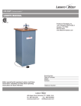
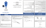
Capp Rondo CR-68 User Guide Contents Standard Parts Listing 2 Introduction 3 Features 4 Specifications 5 Standard Accessories 5 Operating Conditions and Precautions 6 Installation 7 Operation 8-16 Care and Maintenance 17 Service and Repair Information 17 Declaration of Conformity 18 Warranty 19 1 User Guide User Guide STANDARD PARTS LISTING INTRODUCTION PROTECTIVE LID ROTOR SAFETY SWITCH RELEASE BUTTON TIMER KNOB Congratulations you are using the smart microprocessor controlled variable speed and time personal Micro Centrifuge that offers versatility, simplicity, safety and ease of usage in a single package. This product has been designed after studying centrifuges and its usage in innumerable scenarios of the lab environment. The Micro centrifuge is supplied with 2 rotors - round rotor and strip rotor. The 8 x 2/1.5ml rotor can centrifuge up to 8 individual 2/1.5ml plastic micro tubes. The strip tube rotor is designed to centrifuge two strips of 8 x 0.2 ml strip tubes. This Micro Centrifuge can accept many different kinds of micro tubes including 0.2ml, 0.4ml and 0.5ml tubes when used with the reduction adapters supplied along with the unit. This Micro centrifuge is specially suitable for Microfiltration, cell separations, centrifugal tube sedimentation and spin down applications. Please read this manual thoroughly before operating the centrifuge. SPEED KNOB DISPLAY Note : This user guide is intended to assist with the operation and care of the unit only and not for its repair. The customer should not attempt to service or repair the unit. If repairs are required, please contact the supplier. POWER SOCKET NON SLIP RUBBER BASE 2 FUSE ON/OFF SWITCH For your reference, make a note of the serial number, date of purchase and supplier here. Serial No. Purchase Date Supplier 3 User Guide User Guide FEATURES 8POSITION CLOSED MICRO TUBE ROTOR SPECIFICATIONS MOTOR TYPE DC MOTOR MAXIMUM SPEED 6000 rpm SPEED TYPE Variable speed up to 6000 RPM MAX RCF 2000 x g ELECTRONIC SAFETY BRAKE ON LID OPENING FOR USER SAFETY SIZE (LxWxH) 162 x 157 x 116 mm IMBALANCE CUT OFF SAFETY WEIGHT 1.1 Kg LID SAFETY INTERLOCK ELECTRICAL 230 VOLT 50 Hz / 115 VOLT 60 Hz USER CALIBRATION FEATURE POWER CONSUMPTION 30 WATTS STARTS AND STOPS IN SECONDS FUSE DIGITAL DISPLAY SPEED & TIME SETTING KNOBS DIGITAL TIMER PROGRAMMING FUNCTION VARIABLE SPEED SETTINGS RPM INCREMENTS AT 100 RPM 3A,250V SMOOTH AND QUIET RUNNING TINY FOOTPRINT CAN SQUEEZE EASILY ON TO A CROWDED COUNTER TOP EXCELLENT MOTOR AND RUBBER FOOT GRIP ENSURE NOISE FREE SURE FOOTED OPERATION INTERCHANGEABLE ROTORS EXTERNAL SAFETY FUSE STANDARD ACCESSORIES 2/1.5 ml closed rotor PCR strip rotor Allen wrench Replacement fuse (placed in fuse socket) Individual adapters for 0.4/0.5 ml tubes, pack of 8 Individual adapters for 0.2 ml tubes, pack of 8 Power Cable Product user manual & Warranty card 4 5 User Guide User Guide OPERATING CONDITIONS AND PRECAUTIONS INSTALLATION The personal Micro centrifuge is designed to be safe under the following conditions when operated with necessary precautions mentioned hereunder: For indoor use only. Ambient temperature of 4°C to 65°C. Main supply voltage fluctuations not to exceed +/- 10% of the nominal voltage. Position at least 20 cm from walls, 20 cm from ceiling and 20 cm between other products. Make sure to always install the centrifuge on stable flat surfaces only & place it near the electrical outlet. Make sure to always load the rotor symmetrically every time. Each tube should be counterbalanced by another tube. Make sure to always use only specified Micro Centrifuge tubes made from plastic and designed to withstand centrifugal forces of at least 2000 g. Do not use the centrifuge in any manner not specified in these instructions. Do not operate the centrifuge without the rotor being properly attached to the shaft. Re-check by trying to pull it up manually, especially after rotor assembly. Do not move the centrifuge while the rotor is spinning. Do not fill tubes while they are in the rotor, liquid spillage may harm the unit. Do not put hands in the rotor unless the rotor has completely stopped. ON/OFF SWITCH The smart variable speed and time Micro Centrifuge is supplied in a Box. Open the Box, then gently remove centrifuge from the Box and connect the electrical cable. The instruction manual and the accessories should be kept with the centrifuge. Please keep all packaging in safe storage for at least 1 year for warranty purposes. Make sure the rotor is tight enough to avoid any accident. Load the rotor with Micro tubes for centrifugation. Put on the switch on the rear, set the desired speed and time and close the lid to start centrifugation. For More Clarification Refer RCF Chart as below:RCF CHART RPM ROUND ROTOR PCR STRIP 0.2 ml 0.5 ml 1.5 ml 2 ml 1000 35.5 47 52 54 0.2 ml 52 Do not centrifuge flammable, explosive or corrosive materials. Do not use solvents or flammables near this or other electrical equipment. 2000 142 188 208 217 208 3000 319 424 468 488 467 For safety we have provided protective earthing with power supply. 4000 567 753 832 868 830 4500 718 953 1053 1098 1050 5000 886 1177 1300 1356 1297 6000 1276 1695 1872 1952 1868 6 POWER SOCKET PIN FUSE In case of the unit dropping from the table please check the casing for any cracks/damage. The centrifuge and its components are non autoclavable. 7 User Guide User Guide OPERATION Balancing the Rotor To operate this personal Micro Centrifuge below steps should be followed:1. Switch ‘On’ the centrifuge from rear side so that display will show you PICTURE:-1 TO CENTRIFUGE 8 SAMPLES AT A TIME FILL 8 TEST TUBES EQUALLY. THEN INSERT THEM INTO THE HOLES OF THE ROTOR AS SHOWN IN PICTURE 1. PICTURE:-2 TO CENTRIFUGE 4 SAMPLES AT A TIME FILL THE 4 TEST TUBES EQUALLY. THEN INSERT THEM INTO ALTERNATE HOLES OF THE ROTOR AS SHOWN IN PICTURE 2. PICTURE:-3 TO CENTRIFUGE 3 SAMPLES AT A TIME FILL THE 3 TEST TUBES EQUALLY WITH ORIGINAL SAMPLES. THEN INSERT THEN IN ALTERNATE HOLES OF THE ROTOR. NOW FILL A TEST TUBE WITH WATER AND INSERT INTO A HOLE FOR BALANCING THE ROTOR AS SHOWN IN PICTURE 3. the readings. Note : 2. Symbol indicates that Imbalance detection feature is enabled. Load the Rotor symmetrically to avoid accident and damage of centrifuge. 3. Close the lid to start centrifugation. Use the Speed knob to set the speed and the Timer knob to set the run time. 4. Once the centrifugation is completed either use speed knob or use timer knob to bring the display value to zero. This will gradually stop the rotor. 5. If you want to stop the centrifuge quickly, push the lid release button and the rotor will stop within 2 seconds. 6. After the rotor has stopped, press the lid release button and open lid with your thumb in front and fingers on the top - simply lift the lid back on the hinge. In the following pages the routine centrifuge operation procedures are explained in brief. 8 9 User Guide User Guide 1 2 3 0.2 ML 0.4 ML 0.5 ML 4 5 Balancing the Rotor PICTURE:- 4 PICTURE:- 5 PICTURE:- 6 15 11 7 1 3 5 9 13 14 10 6 4 2 8 12 16 10 TO CENTRIFUGE 2 SAMPLES AT A TIME FILL 2 TEST TUBES EQUALLY. THEN INSERT THEM INTO THE HOLES OF ROTOR IN OPPOSITE DIRECTION AS SHOWN IN PICTURE 4. POSITIONS CAN BE 1-5, 2-6, 3-7, 4-8. TO CENTRIFUGE 1 SAMPLE FILL A TEST TUBE WITH SAMPLE THEN INSERT INTO ANY ONE HOLE OF THE ROTOR. NOW INSERT 1 TEST TUBE FILLED WITH WATER IN OPPOSITE DIRECTION OF THE SAMPLE AS SHOWN IN THE PICTURE 5. POSITIONS CAN BE 1-5, 2-6, 3-7, 4-8. TO CENTRIFUGE 16 SAMPLES FILL ALL TEST TUBES WITH SAMPLE. THEN INSERT INTO THE HOLES OF PCR ROTOR IN OPPOSITE DIRECTION AS SHOWN IN THE PICTURE 6. PLACE THE 2 PCR STRIP TUBE IN OPPOSITE DIRECTION. 1.5 ML / 2.0 ML 6 7 8 1.5 ML / 2.0 ML 1.5 ML / 2.0 ML PCR STRIP 1.5 ML / 2.0 ML 8 DIFFERENT TYPES OF TEST TUBES CAN BE CENTRIFUGED BY USING TWO INTERCHANGEABLE ROTORS Interchangeable Rotor ROTOR_8 SLOT PCR ROTOR 8 x 0.2,0.4,0.5,1.5,2 ml 16 x 0.2 ml 11 User Guide User Guide Changing the Rotor Time & Speed Settings and Display Grub Screw To tighten Rotor Wrench To loosen 88 Motor Shaft X 100 RPM Min Speed Time Time control, Speed control Insert the hexagonal Allen wrench into the marked hole provided on the 09 X 100 RPM and display : The unit is equipped with a 0-25 Min side of the rotor. The grub screw is located at the bottom of the rotor on minutes timer. By operating the the marked side. To remove the rotor, turn anticlockwise to loosen the timer knob one can set the desired screw and then gently pull up the rotor up vertically. Insert the new rotor time cycle. The time increments/ from the top onto motor shaft and tighten the screw again. Turn clockwise decrements will be in minutes and time indicator display to tighten screw which is located under the bottom of rotor. Please check will show on display and indicator. the rotor is tight enough to avoid any accident. The timer can be set from 00 to 25 minutes, if the user needs to operate without time control he can change it to next position after 25, ][ X 100 RPM here it will be set to infinite time `][’. Min The timer used is a count down timer and can be reset or adjusted Note in between the runs. 00, actually : Tightening the screw will be in clockwise direction and the loosening will be counter clockwise direction means stop position of centrifuge. infinite time display 12 13 User Guide User Guide 60 X 100 09 RPM Min X 100 RPM Min X 100 time indicator speed indicator RPM Min During the running of centrifuge the time and speed will be displayed alternatively accompanied by speed indicator and time indicator respectively. Quick spin function : By keeping the timer to `][’ position and speed set to any desired setting, one can open and close the lid to operate the centrifuge in quick spin function mode. Speed control : Speed is set by rotating the speed control knob. While adjusting the speed, the speed indicator comes on. The minimum increment or decrement will be to the order of 100 RPM. The speed indicator must be read with a multiplication factor of 100 to get the actual rpm. Speed Time User can activate and deactivate the unbalance detection function by long pressing of the timer knob as shown in above picture. Unbalance detection and cut off Rcf value : Based on the speed and rotor the actual rcf value will vary. One can refer to the table (given on the installation page of this booklet) to get the actual RCF of different rotors at certain given speed values. Imbalance detection Activation/De-activiation When you switch `On’ the centrifuge either it shows ` ’ ` or ’ When imbalance detection is activated X 100 RPM Min X 100 RPM Min ` &’ the centrifuge is running with an unbalanced rotor, (by not placing the weights on the rotor equally and symmetrically) it may lead to excessive vibrations resulting in damage to the centrifuge. This centrifuge has an unique patented feature to protect the centrifuge, its user & the surroundings against such an accidental run. imbalance activated display If the display shows ` ’that means the imbalance detection is activated 14 imbalance de-activated display If the display shows ` ’it means the imbalance detection is de-activated When such an event occurs, the sensor built inside the centrifuge will trigger the shut down of the centrifuge and will also indicate the event by flashing ` : ’ 15 User Guide User Guide CARE & MAINTENANCE Unbalance Indicator User action : Open the lid of centrifuge, correct the unbalanced load by various methods described in balancing the part of this manual. Then close the lid and `reset the centrifuge’. Resetting is done by switching `Off’ and again switching `On’ the centrifuge by using the On/Off switch located on the rear side of the centrifuge. Calibration Switch `On’ the centrifuge from rear side. Long press the speed knob to allow the centrifuge to go into calibration mode. `CL’ will be indicated on display. Run the centrifuge at the preset speed and check the rpm of rotor with the help of an external tachometer. If there is any difference in the set speed & tachometer reading, adjust the speed by rotating the speed knob to match the set speed with tachometer reading. Once the rpm is set, gently long press the speed knob again to save the settings and switch `Off’ the centrifuge from rear side. Upon switching `On’ the centrifuge, the new settings will take effect. 16 Your personal centrifuge and its rotor should be cleaned periodically, ensure that while cleaning the unit is not plugged in. To clean the personal Centrifuge, use a damp cloth and a mild, noncorrosive detergent (ph < 8). Do not immerse the centrifuge in liquid or pour liquids over it. Excessive amounts of liquid should be avoided, Liquid should not come into contact with the motor. After cleaning, ensure all parts are dried thoroughly before attempting to operate the unit. Should a spill of infectious materials occur within the rotor or rotor chamber, the unit should be disinfected. This should be performed by qualified personnel with proper protective equipment. Do not use any cleaning or decontamination methods except those recommended by the manufacturer, check with the manufacturer that the proposed method will not damage the equipment. SERVICE AND REPAIR INFORMATION Any required service should be performed by authorized, qualified personnel only. Repairs performed by unauthorized personnel may void the warranty. X 100 RPM Min Speed Time In event of repairing/warranty claims - before sending the personal centrifuge unit for repairs/warranty claims obtain a service request number based on your product serial number through the authorized supplier. When returning a unit for service, it should be sent in the original packaging. If this is not possible, be sure that the unit is sufficiently packed. Any damage resulting from improper packaging is the responsibility of the customer. Obtain a service request number and send the unit along with the service request number. A written explanation/repair requirement note should accompany the unit along with the service request number. 17 User Guide User Guide DECLARATION OF CONFORMITY WARRANTY STATEMENT This centrifuge has been tested and found to comply with EC standards & This product is warranted to be free from defects in material and approved for CE marking as mentioned below: workmanship for a period of one (1) year from date of purchase. Your product will be duly repaired upon prompt notification in compliance with the following conditions : This warranty is valid only if the product is used for its intended purpose Construction in accordance with the following safety standards and within the guidelines specified in this instruction manual. This EN 61010- 1: 2010 warranty does not cover damage caused by accident, neglect, misuse, EN 61010- 2- 20: 2006 improper service, natural forces or other causes not arising from defects in original material or workmanship. This warranty does not cover any This product is classified as an In-Vitro Device/Equipment incidental or consequential damages, commercial loss or any other IVD compliance under Directive 98/79/EC (Annex III, Section 4 & 5) damages from the use of this product. This warranty does not cover motor brushes, fuses or damage to paint or finish and defects or damages caused by physical and chemical abuse or normal wear and tear. The warranty is invalidated by any non-factory modification, which will immediately terminate all liabilities on us for the products or damages caused by its use. The buyer and its customer shall be responsible for the product or use of products as well as any supervision required for safety. If requested the product must be returned to us or the distributor in well packed and insured manner and all shipping charges must be paid. All items returned for service should be sent postage prepaid in the original packaging or other suitable carton, padded to avoid damage. This warranty is valid only if the warranty registration given herewith is received by us within 30 days from the date of purchase. 18 19