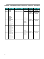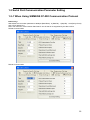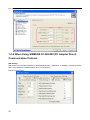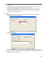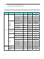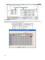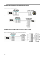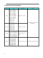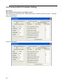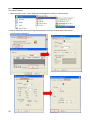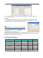
1
PNSPO! NB-series Programmable Terminals HOST CONNECTION MANUAL Cat.No. V108-E1-01 2 Notice OMRON products are manufactured for use according to proper procedures by a qualified operator and only for the purposes described in this manual. The following conventions are used to indicate and classify precautions in this manual. Always heed the information provided with them. Failure to heed precautions can result in injury to people or damage to property. DANGER Indicates an imminently hazardous situation which, if not avoided, will result in death or serious injury. Additionally, there may be severe property damage. WARNING Indicates a potentially hazardous situation which, if not avoided, will result in death or serious injury. Additionally, there may be severe property damage. Caution Indicates a potentially hazardous situation which, if not avoided, may result in minor or moderate injury, or property damage. OMRON Product References All OMRON products are capitalized in this manual. The word “Unit” is also capitalized when it refers to an OMRON product, regardless of whether or not it appears in the proper name of the product. The abbreviation “Ch,” which appears in some displays and on some OMRON products, often means “word” and is abbreviated in documentation in this sense. The abbreviation “PLC” means Programmable Controller. The abbreviation “host” means a controller, such as an IBM PC/AT or compatible computer, that controls a PT (Programmable Terminal). Visual Aids The following headings appear in the left column of the manual to help you locate different types of information. Note Indicates information of particular interest for efficient and convenient operation of the product. Reference Indicates supplementary information on related topics that may be of interest to the users. 1、2、3... 1. Indicates lists of one sort or another, such as procedures, checklists, etc. CS1G-CPU -V1 Boxes in model numbers indicate variable characters. For example: “CS1G-CPU -EV1” indicates the following models: CS1G-CPU42-EV1, CS1G-CPU43-EV1, CS1G- CPU44-EV1 and CS1G-CPU45-EV1. © OMRON,2011 All rights reserved. No part of this publication may be reproduced, stored in a retrieval system, or transmitted, in any form, or by any means, mechanical, electronic, photocopying, recording, or otherwise, without the prior written permission of OMRON. No patent liability is assumed with respect to the use of the information contained herein. Moreover, because OMRON is constantly striving to improve its high-quality products, the information contained in this manual is subject to change without notice. Every precaution has been taken in the preparation of this manual. Nevertheless, OMRON assumes no responsibility for errors or omissions. Neither is any liability assumed for damages resulting from the use of the information contained in this publication. 3 Contents Notice................................................................................................................................................................3 About this Manual .............................................................................................................................................6 Related Manuals...............................................................................................................................................7 Terminology ......................................................................................................................................................8 Introduction .......................................................................................................................................................9 Safety Precautions..........................................................................................................................................10 Precautions for Safe Use................................................................................................................................12 Precautions for Correct Use ...........................................................................................................................14 Conformance to EC Directives .......................................................................................................................15 Read and Understand this Manual .................................................................................................................16 Section 1 Connecting to SIEMENS PLCs ......................................................................................................19 1-1 Serial Port Communication....................................................................................................................... 20 1-2 Serial Port Communication Parameters and Cable Fabrication .............................................................. 21 1-3 Serial Port Communication Parameter Setting ........................................................................................ 22 1-3-1 When Using SIEMENS S7-200 Communication Protocol.................................................. 22 1-3-2 When Using SIEMENS S7-300/400 (PC Adapter Direct) Communication Protocol ........... 23 1-4 Supported Registers................................................................................................................................. 26 1-4-1 SIEMENS S7-200 .............................................................................................................. 26 1-4-2 SIEMENS S7-300/400 (PC Adapter Direct) ....................................................................... 27 1-5 Cable Fabrication ..................................................................................................................................... 28 1-5-1 When Using SIEMENS S7-200 Communication Protocol.................................................. 28 1-5-2 When Using SIEMENS S7-300/400 (PC Adapter Direct) Communication Protocol........... 28 Section 2 Connecting to Mitsubishi PLCs.......................................................................................................29 2-1 Serial Port Communication....................................................................................................................... 30 2-2 Serial Port Communication Parameters and Cable Fabrication .............................................................. 31 2-3 Serial Port Communication Parameter Setting ........................................................................................ 32 2-3-1 When Using Mitsubishi FX1S, Mitsubishi FX0N/1N/2N/3G and Mitsubishi FX3U Communication Protocols .......................................................................................................... 32 2-3-2 When Using Mitsubishi FX-485ADP/485BD/232BD (Multi-station) Communication Protocols .................................................................................................................................... 34 2-3-3 When Using FX2N-10GM/20GM Communication Protocol................................................ 37 2-3-4 When Using Mitsubishi Q00J (CPU Port) Communication Protocol................................... 38 2-3-5 When Using Mitsubishi Q series (CPU Port) Communication Protocol.............................. 38 2-3-6 When Using Mitsubishi Q06H Communication Protocol .................................................... 39 2-3-7 When Using Mitsubishi Q_QnA (Link Port) Communication Protocol ................................ 40 4 2-4 Supported Registers................................................................................................................................. 44 2-5 Cable Fabrication ..................................................................................................................................... 48 2-5-1 FX Series RS232 Communication Cable ........................................................................... 48 2-5-2 FX Series RS485/422 Communication Cable .................................................................... 48 2-5-3 Q Series RS232 Communication Cable............................................................................. 49 2-5-4 Q-Series RS485/422 Communication Cable...................................................................... 49 Section 3 Connecting to Schneider PLCs ......................................................................................................50 3-1 Serial Port Communication....................................................................................................................... 51 3-2 Communication Parameters and Cable Fabrication ................................................................................ 52 3-3 Communication Parameter Setting .......................................................................................................... 53 3-4 Supported Registers................................................................................................................................. 61 3-5 Cable Fabrication ..................................................................................................................................... 61 Section 4 Modbus Connection........................................................................................................................63 4-1 Serial Port Communication....................................................................................................................... 64 4-2 Communication Parameters and Cable Fabrication ................................................................................ 64 4-3 Communication Parameter Setting .......................................................................................................... 65 4-4 Supported Registers................................................................................................................................. 67 4-5 Cable Fabrication ..................................................................................................................................... 68 4-6 Example of NB as Modbus Slave............................................................................................................. 68 Section 5 Connecting to Delta PLCs ..............................................................................................................71 5-1 Serial Port Communication....................................................................................................................... 72 5-2 Communication Parameters and Cable Fabrication ................................................................................ 72 5-3 Communication Parameter Setting .......................................................................................................... 72 5-4 Supported Registers................................................................................................................................. 73 5-5 Cable Fabrication ..................................................................................................................................... 74 Section 6 Connecting to LG PLCs..................................................................................................................75 6-1 Serial Port Communication....................................................................................................................... 76 6-2 Communication Parameters and Cable Fabrication ................................................................................ 76 6-3 Communication Parameter Setting .......................................................................................................... 77 6-4 Supported Registers................................................................................................................................. 81 6-5 Cable Fabrication ..................................................................................................................................... 83 Section 7 Connecting to Panasonic PLCs......................................................................................................85 7-1 Serial Port Communication....................................................................................................................... 86 7-2 Communication Parameters and Cable Fabrication ................................................................................ 86 7-3 Communication Parameter Setting .......................................................................................................... 88 7-4 Supported Registers................................................................................................................................. 89 7-5 Cable Fabrication ..................................................................................................................................... 90 Section 8 List for All PLCs Supported by NB Series ......................................................................................92 8-1 Lists for Supported PLC ........................................................................................................................... 93 5 About this Manual Section 1 Connecting to SIEMENS PLCs This section describes the connection to SIEMENS PLCs . Section 2 Connecting to Mitsubishi PLCs This section describes the connection to Mitsubishi PLCs. Section 3 Connecting to Schneider PLCs This section describes the connection to Schneider PLCs. Section 4 Modbus Connection This section describes the connection on Modbus protocol. Section 5 Connecting to Delta PLCs This section describes the connection to Delta PLCs. Section 6 Connecting to LG PLCs This section describes the connection to LG PLCs . Section 7 Connecting to Panasonic PLCs This section describes the connection to Panasonic PLCs. Section 8 List for All PLCs Supported by NB Series This section lists all PLCs supported by NB Units. WARNING Failure to read and understand the information provided in this manual may result in personal injury or death, damage to the product, or product failure. Please read each section in its entirety and be sure you understand the information provided in the section and related sections before attempting any of the procedures or operations given. 6 Related Manuals The related manuals are as follows: Devices and Software NB series Manual NB series NB Designer Operation Manual NB series Setup Manual NB series Host Connection Manual(This manual) NB series Startup Guide PLC SYSMAC CP series CP1L CPU Unit Operation Manual SYSMAC CP series CP1H/L CPU Unit Programming Manual SYSMAC CP series CP1H CPU Unit Operation Manual SYSMAC CP Series CP1E CPU Unit Hardware USER'S Manual SYSMAC CP Series CP1E CPU Unit Software USER'S Manual SYSMAC C200HX/HG/HE(-E/-ZE) Installation Guide SYSMAC C200HX/HG/HE Operation Manual SYSMAC C200HX/HG/HE(-ZE) Operation Manual SYSMAC CQM1H Operation Manual SYSMAC CPM1A Operation Manual SYSMAC CPM2A Operation Manual SYSMAC CPM1/CPM1A/CPM2A/CPM2C/SRM1(-V2)Programming Manual SYSMAC CPM2C Operation Manual SYSMAC CS1 Series CS1G/H Operation Manual SYSMAC CS/CJ Series Serial Communications Boards and Serial Communications Units Operation Manual SYSMAC CJ Series CJ1G/H(-H) CJ1M CJ1G Operation Manual SYSMAC CS/CJ Series Programming Manual SYSMAC CS/CJ Series INSTRUCTIONS Reference Manual SYSMAC CS/CJ Series Programming Consoles Operation Manual SYSMAC CS/CJ Series Communications Commands Reference Manual SYSMAC CJ Series CJ2 CPU Unit Hardware USER'S Manual SYSMAC CJ Series CJ2 CPU Unit Software USER'S Manual External Tool CX-Programmer Ver.9.□ Operation Manual 7 Manual No. V106 V107 V108 V109 W462 W451 W450 W479 W480 W302 W303 W322 W363 W317 W352 W353 W356 W339 W336 W393 W394 W340 W341 W342 W472 W473 W437 Terminology The following terminology is used in this manual. z About the terminology NB Unit NB Series PLC Indicates the main Unit of the products in the OMRON NB Series of Programmable Terminal. Indicates products in the OMRON NB Series of Programmable Terminal. In this manual, unless otherwise specified, NB Series is taken as the subject concerned. Indicates a Programmable Controller in the OMRON CP, CS/CJ, or SYSMAC C Series of Programmable Controllers. CP Series Indicates the following products in the OMRON PLC Series of Programmable Controllers: CP1H, CP1L, CP1E CS/CJ Series Indicates the following products in the OMRON PLC Series of Programmable Controllers: CS1G, CS1H, CS1G-H, CS1H-H, CJ1G, CJ1M, CJ2M, CJ2H C Series Indicates the following products in the OMRON PLC Series of Programmable Controllers: C200HX(-Z), C200HG(-Z), C200HE(-Z), CQM1, CQM1H, CPM1A, CPM2A, CPM2C Serial Communication Unit Indicates a Serial Communication Unit for an OMRON SYSMAC CS/CJ-Series PLC. Serial Communication Board Indicates a Serial Communication Board for an OMRON SYSMAC CS/CJ-Series or CQM1H PLC. Communication Board Indicates a Communication Board for an OMRON C200HX/HG/HE (-Z) PLC. CPU Unit NB-Designer Host Indicates a CPU Unit in the OMRON CP, CS/CJ or SYSMAC C Series of Programmable Controllers. Indicates the OMRON NB-Designer. Indicates the PLC and other units functioning as the control devices for NB-Series Units. PT Indicates an OMRON Programmable Terminal. HMI Indicates an OMRON Programmable Terminal. 8 Introduction ● Intended Audience This manual is intended for the following personnel, who must also have knowledge of electrical systems (an electrical engineer or the equivalent). y Personnel in charge of introducing FA systems into production facilities. y Personnel in charge of designing FA systems. y Personnel in charge of installing and connecting FA facilities. y Personnel in charge of managing FA systems and facilities. ● General Precautions y The user must operate the product according to the performance specifications described in the operation manuals. y Do not use the PT touch switch input functions for applications where danger to human life or serious property damage is possible, or for emergency switch applications. y Before using the product under conditions which are not described in the manual or applying the product to nuclear control systems, railroad systems, aviation systems, vehicles, combustion systems, medical equipment, amusement machines, safety equipment, and other systems, machines and equipment that may have a serious influence on lives and property if used improperly, consult your OMRON representative. y Make sure that the ratings and performance characteristics of the product are sufficient for the systems, machines, and equipment, and be sure to provide the systems, machines, and equipment with double safety mechanisms. y This manual provides information for connecting and setting up an NB-Series PT. Be sure to read this manual before attempting to use the PT and keep this manual close at hand for reference during installation and operation. 9 Safety Precautions z Notation Used for Safety Information The following notation is used in this manual to provide precautions required to ensure safe usage of the product. The safety precautions that are provided are extremely important to safety. Always read and heed the information provided in all safety precautions. The following notation is used. Indicates a potentially hazardous situation which, if not avoided, will result in minor or moderate injury, or may result in serious injury or death. Additionally, there may be severe property damage. Precautions for Safe Use Indicates the points that should be practiced or avoided for safe usage of the products. Precautions for Correct Use Indicates the points that should be practiced or avoided in order to prevent the product from failure to function, malfunctions or negative impacts on its performance and functionality. z Symbols z Prohibition Indicates a general prohibition. z Disassembling prohibition Any attempts to disassemble the product may result in electric shock or other injuries. DO NOT DISASSEMBLE! z Note Indicates general cautionary, warning, or danger level information. 10 z Warning notation Do not attempt to take the product apart and do not touch the product inside while the power is being supplied. Otherwise it may result in electric shock. Do not touch any internal parts while the power is being supplied. Otherwise it may result in electric shock. Always ensure that the personnel in charge confirm that installation, inspection, and maintenance were properly performed for the NB Unit. “Personnel in charge” refers to individuals qualified and responsible for ensuring safety during machine design, installation, operation, maintenance, and disposal. Ensure that installation and post-installation checks are performed by personnel in charge who possess a thorough understanding of the machinery to be installed. Do not use the input functions of the touch switch, etc. of the NB Unit, in applications that involve human life, in applications that may result in serious injury, or for emergency stop switches. Do not attempt to disassemble, repair, or modify the NB Unit. Otherwise it may cause NB Unit to lose its safety functions. Never press more than two points on the touch panel of the NB Unit at a time. Otherwise, it may activate a switch somewhere between the two points. 11 Precautions for Safe Use ● When unpacking the NB Unit, check carefully for any external scratches or other damages. Also, shake the Units gently and check for any abnormal sound. ● The NB Unit must be installed in a control panel. ● The mounting panel must be between 1.6 and 4.8 mm thick. Tighten the Mounting Brackets evenly to a torque of between 0.5 and 0.6 N·m to maintain water and dust resistance. If the tightening torque exceeds the specified value, or the tightening is not even, deformation of the front panel may occur. What is more, make sure the panel is not dirty or warped and that it is strong enough to hold the Units. ● Do not let metal particles enter the Units when preparing the panel. ● Do not connect an AC power supply to the DC power terminals. ● Use a DC power with a slight voltage fluctuation and that will provide a stable output even if the input is momentarily interrupted for 10 ms. Rated Power Supply Voltage: DC 24 V (Allowable range DC 20.4~27.6 V) ● Do not perform a dielectric voltage test. ● Make the connection by using terminal screws crimping on a twisted-pair cable with a crimping range of 12~26 AWG, and only 6.5 mm of insulation peel of the cable needs to be peeled off. Tighten the terminal screws at a torque of between 0.3 and 0.5 N·m. Make sure the screws are properly tightened. ● To prevent malfunctions caused by noise, ground the Unit correctly. ● Do not touch the packaging part of the circuit board with your bare hands. Discharge any static electricity from your body before handling the board. ● When using the No. 6 pin of the serial communication port COM1 connector for a voltage of DC+5 V, make sure the supply equipment’s current capacity is below 250 mA before using it. The DC+5V voltage output of the NB main unit is +5V±5%, and the maximum current is 250 mA. ● Turn OFF the power supply before connecting or disconnecting cables. ● Always keep the connector screws firmly tightened after the communication cable is connected. ● The maximum tensile load for cables is 30 N. Do not apply loads greater than this. ● Confirm the safety of the system before turning ON or OFF the power supply, or pressing the reset button. ● The whole system may stop depending on how the power supply is turned ON or OFF. Turn ON/OFF the power supply according to the specified procedure. ● Reset by pressing the reset button, or restart the power supply, once the DIP switch settings are changed. ● To ensure the system’s safety, make sure to incorporate a program that can confirm the normal functionality of the NB Unit before running the system. ● Start actual system application only after sufficiently checking screen data, macros and the operation of the program at the host side. ● Don’t press the touch panel with a force greater than 30 N. ● Do not use a screwdriver or any other tool to press the touch panel. ● Confirm the safety of the system before pressing the touch panel. 12 ● Signals from the touch switches may not be input if the touch switches are pressed consecutively at high speed. Confirm that the PT has detected the input of a touch switch before pressing any other touch switch. ● Do not accidentally press the touch panel when the backlight is not lit or when the display does not appear. Make sure of the safety of the system before pressing the touch panel. ● To use numeric input functions safely, always make maximum and minimum limit set- tings. ● Before initializing screen data, confirm that existing data is backed up at the NB-Designer. ● When changing the password with the system menu, do not reset or turn OFF the power supply until writing is finished. Failure to save the password may cause the screen to fail to function. ● When using an equipment monitor, confirm the safety of the system before carrying out the following operations: y Changing monitor data. y Changing operation mode. y Forced setup/reset. y Changing the current value or the set value. ● Do not connect a USB connector to any device that is not applicable. ● Before connecting a USB connector to a device, make sure that the device is free of damage. ● Commercially available and the recommended USB HUB are different from the general specifications of the NB Unit. The unit may not function well in an environment subject to noise, static electricity. Therefore, when using a USB HUB, employ sufficient noise and static electricity insulation measures, or install it at a site free of noise or static electricity. ● While uploading or downloading screen data or system programs, do not perform the following operations that may corrupt the screen data or the system program: y Turning OFF the power supply of the NB Unit. y Pressing the PT’s reset switch. ● Dispose of the Units and batteries according to local ordinances as they apply. ● When exporting products with lithium primary batteries containing perchlorate at 6ppb or above to or delivering them through California, USA, the following precautionary measures have to be publicized. Perchlorate material – applicable through special processing. Refer to http://www.dtsc.ca.gov/hazardouswaste/perchlorate. NB-Series products contain lithium primary batteries. When exporting products containing this kind of batteries to or delivering them through California, USA, label all the product packages as well as the appropriate delivery packages. ● Do not use benzene, paint thinner, or other volatile solvents, and do not use chemically treated cloths. ● Do not dispose the Units together with general waste at waste yards. When disposing them, follow the related local ordinances or rules. ● Customers may not replace the backlight lamp inside the NB Unit. Please contact OMRON’s customer service center. 13 ● Deterioration over time can cause the touch points to move. Calibrate the touch panel periodically. ● Water and oil resistance will be lost if the front sheet is torn or is peeling off. Do not use the Unit, if the front sheet is torn or is peeling off. ● The rubber packing will deteriorate, shrink, or harden depending on the operating environment. Inspect and replace the rubber packing periodically. ● The communication cables of the COM1 and COM2 connectors are not interchangeable. Confirm the pins of the ports before carrying out communications. ● Periodically check the installation conditions in applications where the PT is subject to contact with oil or water. Precautions for Correct Use z Do not install the product in any of the following locations: Locations subject to severe changes in temperature Locations subject to temperatures or humidity outside the range specified in the specifications Locations subject to condensation as the result of high humidity Locations subject to corrosive or flammable gases Locations subject to strong shock or vibration Locations outdoors subject to direct wind and rain Locations subject to strong ultraviolet light Locations subject to dust Locations subject to direct sunlight Locations subject to splashing oil or chemicals z Take appropriate and sufficient countermeasures when installing systems in the following locations: Locations subject to static electricity or other forms of noise Locations subject to strong electric field or magnetic field Locations close to power supply lines Locations subject to possible exposure to radioactivity 14 Conformance to EC Directives NB-Series Programmable Terminals are EMC compliant. 1 Concepts OMRON products are electronic devices that are incorporated in machines and manufacturing installations. OMRON PTs conform to the related EMC Directives (see note) so that the devices and machines into which they are built can more easily conform to EMC Directives. The actual products have been through inspections and are completely in accordance with EMC directives. However, when they are built into customers’ systems, whether the systems also comply with these Directives is up to the customers for further inspection. EMC-related performance of OMRON PTs will vary depending on the configuration, wiring, and other conditions of the OMRON equipment or control panel. The customer must, therefore, perform final checks to confirm that the overall machine or device conforms to EMC standards. Note The applicable EMC (Electromagnetic Compatibility) standards are as follows: EMS (Electromagnetic sensitivity): EN61131-2: 2007 EMI (Electromagnetic Interference): EN61131-2: 2007 2 Conformance to EC Directives NB-Series Programmable Terminals are EC compliant. Heed the following precautions in order to ensure that the customer’s overall machine and device conform to EC Directives. 1. The PT is intended to be installed in a control panel. 2. You must use reinforced insulation or double insulation for the DC power supply and the DC power supply must have minimal voltage fluctuations and provide a stable output even if the power supply input is interrupted for 10 ms. 3. The PTs conform to the standard EN 61131-2, but radiated emission characteristics (10m regulations) may vary depending on the configuration of the control panel used, other devices connected to the control panel, wiring, and other conditions. You must therefore confirm that the overall machine or equipment complies with EC Directives. 4. This is a class A product (Product for industry purpose). It may cause radio interference in residential areas, in which case the user may be required to take adequate measures to reduce interference. 15 Read and Understand this Manual Please read and understand this manual before using the product. Please consult your OMRON representative if you have any questions or comments. Warranty and Limitations of Liability WARRANTY OMRON’S EXCLUSIVE WARRANTY IS THAT THE PRODUCTS ARE FREE FROM DEFECTS IN MATERIALS AND WORKMANSHIP FOR A PERIOD OF ONE YEAR (OR OTHER PERIOD IF SPECIFIED) FROM DATE OF SALE BY OMRON. OMRON MAKES NO WARRANTY OR REPRESENTATION, EXPRESS OR IMPLIED, REGARDING NONINFRINGEMENT, MERCHANTABILITY, OR FITNESS FOR PARTICULAR PURPOSE OF THE PRODUCTS. ANY BUYER OR USER ACKNOWLEDGES THAT THE BUYER OR USER ALONE HAS DETERMINED THAT THE PRODUCTS WILL SUITABLY MEET THE REQUIREMENTS OF THEIR INTENDED USE. OMRON DISCLAIMS ALL OTHER WARRANTIES, EXPRESS OR IMPLIED. LIMITATIONS OF LIABILITY OMRON SHALL NOT BE RESPONSIBLE FOR SPECIAL, INDIRECT, OR CONSEQUENTIAL DAMAGES, LOSS OF PROFITS OR COMMERCIAL LOSS IN ANY WAY CONNECTED WITH THE PRODUCTS, WHETHER SUCH CLAIM IS BASED ON CONTRACT, WARRANTY, NEGLIGENCE, OR STRICT LIABILITY. IN NO EVENT SHALL THE RESPONSIBILITY OF OMRON FOR ANY ACT EXCEED THE INDIVIDUAL PRICE OF THE PRODUCT ON WHICH LIABILITY IS ASSERTED. IN NO EVENT SHALL OMRON BE RESPONSIBLE FOR WARRANTY, REPAIR, OR OTHER CLAIMS REGARDING THE PRODUCTS UNLESS OMRON’S ANALYSIS CONFIRMS THAT THE PRODUCTS WERE PROPERLY HANDLED, STORED, INSTALLED, AND MAINTAINED AND NOT SUBJECT TO CONTAMINATION, ABUSE, MISUSE, OR INAPPROPRIATE MODIFICATION OR REPAIR. 16 Application Consideration SUITABILITY FOR USE OMRON shall not be responsible for conformity with any standards, codes, or regulations that apply to the combination of products in the customer’s application or use of the products. At the customer’s request, OMRON will provide applicable third party certification documents identifying ratings and limitations of use that apply to the products. This information by itself is not sufficient for a complete determination of the suitability of the products in combination with the end product, machine, system, or other application or use. The following are some examples of applications for which particular attention must be given. This is not intended to be an exhaustive list of all possible uses of the products, nor is it intended to imply that the uses listed may be suitable for the products: • Outdoor use, uses involving potential chemical contamination or electrical interference, or conditions or uses not described in this manual. • Nuclear energy control systems, combustion systems, railroad systems, aviation systems, medical equipment, amusement machines, vehicles, safety equipment, and installations subject to separate industry or government regulations. • Systems, machines, and equipment that could present a risk to life or property. Please know and observe all prohibitions of use applicable to the products. NEVER USE THE PRODUCTS FOR AN APPLICATION INVOLVING SERIOUS RISK TO LIFE OR PROPERTY WITHOUT ENSURING THAT THE SYSTEM AS A WHOLE HAS BEEN DESIGNED TO ADDRESS THE RISKS, AND THAT THE OMRON PRODUCTS ARE PROPERLY RATED AND INSTALLED FOR THE INTENDED USE WITHIN THE OVERALL EQUIPMENT OR SYSTEM. PROGRAMMABLE PRODUCTS OMRON shall not be responsible for the user’s programming of a programmable product, or any consequence thereof. 17 Disclaimers CHANGE IN SPECIFICATIONS Product specifications and accessories may be changed at any time based on improvements and other reasons. It is our practice to change model numbers when published ratings or features are changed, or when significant construction changes are made. However, some specifications of the products may be changed without any notice. When in doubt, special model numbers may be assigned to fix or establish key specifications for your application on your request. Please consult with your OMRON representative at any time to confirm actual specifications of purchased products. DIMENSIONS AND WEIGHTS Dimensions and weights are nominal and are not to be used for manufacturing purposes, even when tolerances are shown. PERFORMANCE DATA Performance data given in this manual is provided as a guide for the user in determining suitability and does not constitute a warranty. It may represent the result of OMRON’s test conditions, and the users must correlate it to actual application requirements. Actual performance is subject to the OMRON Warranty and Limitations of Liability. ERRORS AND OMISSIONS The information in this manual has been carefully checked and is believed to be accurate. however, no responsibility is assumed for clerical, typographical, or proofreading errors, or omissions. 18 Section 1 Connecting to SIEMENS PLCs This section describes the connection to SIEMENS PLCs. 1-1 Serial Port Communication....................................................................................................................... 20 1-2 Serial Port Communication Parameters and Cable Fabrication.................................................................. 21 1-3 Serial Port Communication Parameter Setting ........................................................................................ 22 1-4 Supported Registers................................................................................................................................. 26 1-5 Cable Fabrication ..................................................................................................................................... 28 19 1-1 Serial Port Communication Series CPU Link Module Driver CPU212 CPU214 CPU215 CPU216 S7-200 CPU221 CPU222 RS485 on the CPU unit SIEMENS S7-200 CPU224 CPU226 CPU224 XP CN CPU226 XP CN CPU312IFM CPU313 CPU313C CPU314 S7-300 CPU314IFM CPU315 MPI port on the CPU unit CPU315-2 DP CPU316 CPU316-2 DP CPU318-2 SIEMENS S7-300/400 (PC Adapter CPU412-1 Direct) CPU412-2 DP CPU413-1 CPU413-2 DP CPU414-1 S7-400 CPU414-2 DP MPI port on the CPU unit CPU414-3 DP CPU416-1 CPU416-2 DP CPU416-3 DP CPU417-4 20 1-2 Serial Port Communication Parameters and Cable Fabrication Series CPU Link Module CPU222 RS232 CPU224 S7-200 CPU226 COMM Type RS485 on the CPU unit CPU224 XP CN RS485 CPU226 XP CN Parameter Cable Refer to Self-made cable Section 1-3 required Refer to Self-made cable Section 1-3 required Refer to Self-made cable Section 1-3 required Refer to Self-made cable section 1-3 required CPU312IFM CPU313 CPU313C RS232 CPU314 S7-300 CPU314IFM CPU315 S7-300/400 MPI port on the CPU unit (PC Adapter Direct) CPU315-2 DP protocol CPU316 CPU316-2 DP CPU318-2 CPU412-1 CPU412-2 DP CPU412-3H CPU413-1 RS232 CPU413-2 DP S7-400 CPU414-1 CPU414-2 DP CPU414-3 DP CPU416-1 CPU416-2 DP CPU416-3 DP CPU417-4 21 S7-300/400 MPI port on the CPU unit (PC Adapter Direct) protocol 1-3 Serial Port Communication Parameter Setting 1-3-1 When Using SIEMENS S7-200 Communication Protocol HMI Settings HMI default communication parameters: 9600bps (Baud Rate),8 (Data Bit),1(Stop Bit),even(Parity Check) and 0 (PLC Station No.) Note: The maximum communication baud rate is 187.5K that is not supported by the direct online. RS485 Communication RS232 Communication 22 PLC Settings 1-3-2 When Using SIEMENS S7-300/400 (PC Adapter Direct) Communication Protocol HMI Settings HMI default communication parameters: 19200bps(Baud Rate),8(Data Bit),2(Stop Bit),odd (Parity Check) and 2 (PLC Station No.) (Multiple Station No. is not supported.) RS232 Communication 23 Note: 1. The PLC Station No. is not needed if the PC adapter is used, which realize one for one communication. 2. The PLC baud rate and HMI baud rate are set to 187.5Kbps and 19200bps respectively when 6ES7972-0CA1 -0XA0 adapter is used to perform communications. 3. DB blocks should be established in PLC program configuration, otherwise the relevant registers (DB.DBX, DB.DBW, DB.DBD)can not be written. The even parity should be used on the initial addresses of DBm.DBW and DBm.DBD. PLC Settings 1. The PLC baud rate at MPI port is set to 187.5Kbps when 6ES7972-0CA1 -0XA0 adapter(HMI Adapter)is used to perform communications. 2. The MPI address must be 2. 3. Download the set parameters to PLC after the setting is completed. Then open [SIMATIC Manager] menu-[Option]-[PG/PC Interface Setting], select PC Adapter (MPI) and modify the transmission rate of MPI port to be 187.5K, as shown below: 24 25 1-4 Supported Registers 1-4-1 SIEMENS S7-200 Device Bit Address Word Address Format S.B 0.0-31.7 ------ DD.O SM.B 0.0-549.7 ------ DDD.O Counter Bit Cnt 0-255 ------ DDD.O Counter Bit Tim 0-255 ------ DDD.O V.B 0.0-10238.7 ------ DDDDD.O M.B 0.0-31.7 ------ DD.O Q.B 0.0-15.7 ------ DD.O I.B 0.0-15.7 ------ DD.O Analog Output ------ AQW 0-62 DD Analog Input: ------ AIW 0-62 DD SCR (32-bit) ------ SD 0-28 DD SCR ------ SW 0-30 DD ------ SMD 0-546 DDD Special Memory Registers ------ SMW 0-548 DDD Internal Memory Bit (32-bit) ------ MD 0-28 DD Internal Memory ------ MW 0-30 DD ------ QD 0-12 DD ------ QW 0-14 DD ------ ID 0-12 DD ------ IW 0-14 DD Counter PV ------ Cnt 0-255 DDD Timer PV ------ Tim 0-255 DDD Variable Memory (32-bit) ------ VD 0-10236 DDDDD Variable Memory ------ VW 0-10238 DDDDD SCR Nodes Special Memory Bit Variable Memory Nodes Internal Memory Bit Discrete Output and Map Register Nodes Discrete Input and Map Register Nodes Special Memory Registers (32-bit) Discrete Output and Map Registers (32-bit) Discrete Output and Map Registers Discrete Input and Map Registers (32-bit) Discrete Input and Map Registers Notes Note: The initial addresses of VW and VD must be even. Address format description: D: decimal, O: octonary, H: hexadecimal. 26 1-4-2 SIEMENS S7-300/400 (PC Adapter Direct) Device Bit Address Word Address Format External Input Nodes I 0.0~511.7 ------ DDDD.O External Output Nodes Q 0.0~511.7 ------ DDDD.O Internal Auxiliary Nodes M 0.0~4095.7 ------ DDDD.O Data Register Nodes DBm.DBX 0~65535.7 ------ DDDDD.O m:10~60 Data Registers ------ DBm.DBW 0-65534 DDDDD m:10~60 Data Registers (32-bit) ------ DBm.DBD 0-65532 DDDDD m:10~60 Internal Registers ------ MW 0~2046 DDDD Internal Registers (32-bit) ------ MD 0~2044 DDDD ------ QW 0~126 DDD ------ QD 0~124 DDD ------ IW 0~126 DDD ------ ID 0~124 DDD External Output Registers External Output Registers (32-bit) External Input Registers External Input Registers (32-bit) Note: The initial addresses of DBm.DBW and DBm.DBD must be even. Address format description: D: decimal, O: octonary, H: hexadecimal. 27 Notes 1-5 Cable Fabrication 1-5-1 When Using SIEMENS S7-200 Communication Protocol RS232 Communication Cable Use serial port programming cable manufactured by SIEMENS to communicate with HMI. RS485 Communication Cable 1-5-2 When Using SIEMENS S7-300/400 (PC Adapter Direct) Communication Protocol RS232 Communication Cable Use 6ES7972-0CA1 -0XA0 communication cables for HMI Adapter to perform communications. 28 Section 2 Connecting to Mitsubishi PLCs This section describes the connection to Mitsubishi PLCs. 2-1 Serial Port Communication....................................................................................................................... 30 2-2 Serial Port Communication Parameters and Cable Fabrication.................................................................. 31 2-3 Serial Port Communication Parameter Setting ........................................................................................ 32 2-4 Supported Registers................................................................................................................................. 44 2-5 Cable Fabrication ..................................................................................................................................... 48 29 2-1 Serial Port Communication Series CPU Link Module Driver RS232 on the CPU unit FX1S RS485 on the CPU unit FX -422-BD *3 FX -485-BD *3 FX -485-ADP *3 Mitsubishi FX1S *2 Mitsubishi FX1S *2 Mitsubishi (Multi-station) *1 FX-485ADP/485BD/232BD RS232 on the CPU unit FX0N FX1N FX1NC FX2N FX2NC FXCPU RS485 on the CPU unit FX -422-BD *3 Mitsubishi FX0N/1N/2N/3G *2 FX -485-BD *3 FX -485-ADP *3 Mitsubishi FX0N/1N/2N/3G *2 Mitsubishi FX-485ADP/485BD/232BD (Multi-station) *1 FX -232-BD *3 FX2N-10GM FX2N-20GM RS232 on the CPU unit RS485 on the CPU unit Mitsubishi FX2N_10GM/20GM RS232 on the CPU unit FX3U FX3UC RS485 on the CPU unit FX -422-BD *3 Mitsubishi FX3U *2 FX -485-BD *3 FX -485-ADP *3 Mitsubishi FX3U *2 Mitsubishi (Multi-station) *1 FX -232-BD *3 FX3G Q00JCPU QCPU Q00CPU Q01CPU RS232 on the CPU unit RS485 on the CPU unit RS232 on the CPU unit QJ71C24 QJ71C24-R2 QJ71C24N QJ71C24N-R2 QJ71C24N-R4 RS232 on the CPU unit QJ71C24 QJ71C24-R2 QJ71C24N QJ71C24N-R2 QJ71C24N-R4 FX-485ADP/485BD/232BD Mitsubishi FX0N/1N/2N/3G *2 Mitsubishi Q00J (CPU Port) Mitsubishi Q_QnA (Link Port) Mitsubishi Q_QnA (Link Port) RS232 on the CPU unit Mitsubishi Q Series (CPU Port) Q02CPU Q02HCPU Q12HCPU Q25HCPU QJ71C24 QJ71C24-R2 QJ71C24N QJ71C24N-R2 QJ71C24N-R4 Mitsubishi Q_QnA (Link Port) Q06HCPU RS232 on the CPU unit Mitsubishi Q06H 30 Note: 1. *1 This protocol supports Multiple Station No.. 2. *2 This protocol doesn’t support Multiple Station No.. 3. *3 is the module type applicable to this PLC. 2-2 Serial Port Communication Parameters and Cable Fabrication Series CPU COMM Type Refer to Section 2-3 Self-made cable required RS485 on the CPU unit FX -422-BD RS422 Refer to Section 2-3 Self-made cable required FX -485-BD FX -485-ADP RS422 Refer to Section 2-3 Self-made cable required RS232 on the CPU unit RS232 Refer to Section 2-3 Self-made cable required RS485 on the CPU unit FX -422-BD RS422 Refer to Section 2-3 Self-made cable required FX -485-BD FX -485-ADP RS422 Refer to Section 2-3 Self-made cable required FX -232-BD RS232 Refer to Section 2-3 Self-made cable required RS232 on the CPU unit RS232 Refer to Section 2-3 Self-made cable required RS485 on the CPU unit RS422 Refer to Section 2-3 Self-made cable required RS232 on the CPU unit RS232 Refer to Section 2-3 Self-made cable required RS485 on the CPU unit RS422 Refer to Section 2-3 Self-made cable required RS232 on the CPU unit RS232 Refer to Section 2-3 Self-made cable required RS485 on the CPU unit FX -422-BD RS422 Refer to Section 2-3 Self-made cable required FX -485-BD FX -485-ADP RS422 Refer to Section 2-3 Self-made cable required FX -232-BD RS232 Refer to Section 2-3 Self-made cable required Q00JCPU RS232 on the CPU unit RS232 Refer to Section 2-3 Self-made cable required Q00CPU Q01CPU RS232 on the CPU unit RS232 Refer to Section 2-3 Self-made cable required FX2N-10GM FX2N-20GM FX3G FX3UC FX3U 31 Cable RS232 FX0N FX1N FX1NC FX2N FX2NC Melsec Q Parameter RS232 on the CPU unit FX1S FXCPU Link Module QJ71C24 QJ71C24-R2 QJ71C24N QJ71C24N-R2 RS232 Refer to Section 2-3 Self-made cable required QJ71C24 QJ71C24N QJ71C24N-R4 RS422 Refer to Section 2-3 Self-made cable required Q02CPU Q02HCPU Q12HCPU Q25HCPU RS232 on the CPU unit RS232 Refer to Section 2-3 Self-made cable required Q06HCPU RS232 on the CPU unit RS232 Refer to Section 2-3 Self-made cable required Q00JCPU Q00CPU Q01CPU Q02CPU Q02HCPU Q12HCPU Q25HCPU 2-3 Serial Port Communication Parameter Setting 2-3-1 When Using Mitsubishi FX1S, Mitsubishi FX0N/1N/2N/3G and Mitsubishi FX3U Communication Protocols HMI Settings HMI default communication parameters: 9600bps (Baud Rate), 7 (Data Bit), even (Parity Check), 1 (Stop Bit) and 0 (PLC Station No.) The PLC Communication Time Out, Max interval of word (bit) block pack, Max word block package size on the right vary with PLC protocols. Generally the defaults are selected. RS422 Communication 32 RS232 Communication PLC Settings The PLC setting is as shown below when Mitsubishi FX1S, Mitsubishi FX0N/1N/2N/3G and Mitsubishi FX3U communication protocols are used: Click the [Default] button to make settings without checking the [Communication Setting]: Note: 1. The communication protocols such as Mitsubishi FX1S, Mitsubishi FX0N/1N/2N/3G and Mitsubishi FX3U etc. can be selected according to PLC model if the Station No. is not used when the communication is realized through the communication function expansion board. 2. Make sure the value of communication format D8120 is 0 when the communication is realized through the communication function expansion board. 33 2-3-2 When Using Mitsubishi FX-485ADP/485BD/232BD (Multi-station) Communication Protocols HMI Settings HMI default communication parameters: 19200bps (Baud Rate), 7(Data Bit), even (Parity Check), 2 (Stop Bit) and 0 (PLC Station No.) Note: The protocols are only applicable to PLCs communicating through communication function expansion board and support Multiple Station No. and Baud Rate settings. RS422 Communication RS232 Communication 34 PLC Settings The PLC setting is as shown below when FX-485ADP/485BD/232BD (Multi-station) communication protocols are used: Double-click the [PLC Parameter] under [Project Data List] in GX Developer software: Open the [FX Parameter] dialog box: 1. FX1S/FX1N/FX2N/3G Series PLC Check the [Operate communication setting] option. Note: 1. FX0N Series PLCs do not support the [FX Parameter] operation, but the communication parameters can be set through writing values to the special data registers D8120, D8121and D8129. 2. The [Dedicated Protocol] must be selected and the [Sum Check] must be checked with [Form4] selected for the Transmission Control Sequence. 3. The [H/W Type] is “Regular/RS-232C” and “RS-485” when FX -232-BD and FX -485-BD/FX -485-ADP communication are used respectively. 35 2. FX3U/3UC Series PLC Check the [Operate communication setting] option. Note: 1. The [CH1] should be selected for FX3U/3UC Series PLC. 2. The [Dedicated Protocol] must be selected and the [Sum Check] must be checked with [Form4] selected for the Transmission Control Sequence. 3. The [H/W Type] is “Regular/RS-232C” and “RS-485” when FX -232-BD and FX -485-BD/FX -485-ADP communication are used respectively. Aside from using [FX Parameter], the user can use the special data register D8120 in PLC to set the communication parameters for PLC. Special Data Registers Descriptions D8120 Communication format D8121 Station No. setting D8129 Data network out-time counting Applicable to FX3U/3UC and other FX Series PLCs using CH1 For example: If the PLC communication parameters are: 9600bps (Baud Rate), 7 (Data Bit), even (Parity Check), 2 (Stop Bit), 1(PLC Station No.), RS485 (Communication Method) and 1 (PLC Communication Time Out), then D8120=0xE08E, D8121=1, and D8129=1. Note: The settings will be valid when the PLC is turned OFF and then back ON again after the D8120 setting is modified. 36 2-3-3 When Using FX2N-10GM/20GM Communication Protocol HMI Settings HMI default communication parameters: 9600bps (Baud Rate), 8 (Data Bit), even (Parity Check), 1 (Stop Bit) and 0 (PLC Station No.) RS232 Communication RS422 Communication 37 2-3-4 When Using Mitsubishi Q00J (CPU Port) Communication Protocol HMI Settings HMI default communication parameters: 115200bps (Baud Rate), 8 (Data Bit), odd (Parity Check), 1 (Stop Bit) and 0 (PLC Station No.) (Multiple Station No. is not supported.) RS232 Communication Note: There is no need to set PLC baud rate that will automatically vary with the baud rate set by HMI. 2-3-5 When Using Mitsubishi Q series (CPU Port) Communication Protocol HMI Settings HMI default communication parameters: 115200bps (Baud Rate), 8 (Data Bit), odd (Parity Check), 1 (Stop Bit) and 0 (PLC Station No.) (Multiple Station No. is not supported.) 38 RS232 Communication Note: There is no need to set PLC baud rate that will automatically vary with the baud rate set by HMI. 2-3-6 When Using Mitsubishi Q06H Communication Protocol HMI Settings HMI default communication parameters: 115200bps (Baud Rate), 8 (Data Bit), odd (Parity Check), 1 (Stop Bit) and 0 (PLC Station No.) (Multiple Station No. is not supported.) RS232 Communication Note: There is no need to set PLC baud rate that will automatically vary with the baud rate set by HMI. 39 2-3-7 When Using Mitsubishi Q_QnA (Link Port) Communication Protocol HMI Settings HMI default communication parameters: 9600bps (Baud Rate), 8 (Data Bit), odd (Parity Check), 1 (Stop Bit) and 0 (PLC Station No.) RS232 Communication RS422 Communication 40 PLC Settings The PLC settings is as shown below when Mitsubishi Q_QnA (Link Port) or Mitsubishi Melsec Q communication protocols are used: 1. Communication through CPU Port 2. Communication through C24 Serial Port Communication Module a. Open [Parameter] on Project Data List and double-click [PLC parameter], and select [I/O assignment] after the [Qn (H) Parameter] dialog box is opened. 41 b. Click the [Type] dropdown list to select the [Intelli.] option. c. Click the [Switch setting] button and make settings as shown below: The attribute descriptions of Switch1, Switch2, Switch3, Switch4 and Switch5 are as shown below: 42 Setting Example: The Switch3, Switch4 and Switch5 can be set as shown below if the CH2 RS422 communication parameters and Station No. are set to 19200/8/Odd/1 and 0 respectively: 43 The Switch1, Switch2 and Switch5 can be set as shown below if the CH1 RS232 communication parameters and Station No. are set to 19200/8/Odd/1 and 0 respectively: The difference between Mitsubishi Q_QnA (Link Port) protocol and Mitsubishi Melsec Q protocol: 1. Mitsubishi Q_QnA (Link Port) protocol features fast communication speed while RS232 communication of module is not supported. 2. Mitsubishi Melsec Q protocol features support for RS232 and RS485 communications of module while the communication speed is slower. 2-4 Supported Registers FX1S Device Bit Address Word Address Format Notes Input Relay X 00-17 ------ OO Output Relay Y 00-15 ------ OO Internal Relay M 000-511 ------ DDD Timer Contact T 00-63 ------ DD Counter Contact C 00-31 ------ DD Data Contact D 000.0-255.F ------ DDD.H State S 000-127 ------ DDD Timer Value ------ T 00-63 DD Counter Value ------ C 00-31 DD Data Register ------ D 000-255 DDD Special Data Register ------ SD 8000-8255 DDDD Counter Value ------ C_dword 235-255 DDD 32 bit device Device Bit Address Word Address Format Notes Input Relay X 000-177 ------ OOO Output Relay Y 000-177 ------ OOO Internal Relay M 0000-1535 ------ DDDD Timer Contact T 000-255 ------ DDD Counter Contact C 000-199 ------ DDD Special Internal Relay SM 8000-8255 ------ DDDD FX1N/FX1NC 44 State S 000-999 ------ DDD Timer Value ------ T 000-255 DDD Counter Value ------ C 000-199 DDD Data Register ------ D 0000-7999 DDDD Special Data Register ------ SD 8000-8255 DDDD Counter Value ------ C_dword 200-255 DDD 32 bit device Device Bit Address Word Address Format Notes Input Relay X 000-377 ------ OOO Output Relay Y 000-377 ------ OOO Internal Relay M 0000-3071 ------ DDDD Timer Contact T 000-255 ------ DDD Counter Contact C 000-199 ------ DDD Special Internal Relay SM 8000-8255 ------ DDDD State S 000-999 ------ DDD Timer Value ------ T 000-255 DDD Counter Value ------ C 000-199 DDD Data Register ------ D 0000-7999 DDDD Special Data Register ------ SD 8000-8255 DDDD Counter Value ------ C_dword 200-255 DDD 32 bit device Device Bit Address Word Address Format Notes Input Relay X 00-67 ------ OO *1 Output Relay Y 00-67 ------ OO *1 Internal Relay M 000-511 ------ DDD *1 Special Internal Relay SM9000-9175 ------ DDDD *1 Data Register ------ D 000-3999 DDDD *2 Special Data Register ------ SD 9000-9599 DDDD *2 Special Data Register ------ FD 4000-6999 DDDD *2 FX2N/FX2NC FX2N-10GM/20GM *1 does not support batch transmission while *2 supports batch transmission. FX3UC 45 Device Bit Address Word Address Format Input Relay X000-377 ------ OOO Output Relay Y000-377 ------ OOO Timer Contact T_bit 000-511 ------ DDD Counter Contact C_bit 000-199 ------ DDD Notes Data Contact D_bit0.0-7999.F ------ DDDD.H State S0000-4095 ------ DDDD Internal Relay M0000-7679 ------ DDDD Special Internal Relay SM8000-8511 ------ DDDD Timer Value ------ T000-511 DDD Counter Value ------ C000-199 DDD Data Register ------ D0000-7999 DDDD Extension Register ------ R0000-32767 DDDDD Special Data Register ------ SD8000-8511 DDDD Counter Value ------ C_dword200-255 DDD 32 bit device Q00JCPU Device Bit Address Word Address Counter Coil CC0-1023 DDDD Counter Contact CS0-1023 DDDD Timer Coil TC0-2047 DDDD Timer Contact TS0-2047 DDDD Special Link Relay SB000-7FF ------ HHH Link Relay B0000-1FFF ------ HHHH Step Relay S0000-1FFF ------ HHHH Edge Relay V0000-2047 ------ DDDD Annunciator F0000-2047 ------ DDDD Latch Relay L0000-8191 ------ DDDD Special Internal Relay SM0000-2047 ------ DDDD Internal Relay M0000-8191 ------ DDDD Output Relay Y0000-1FFF ------ HHHH Input Relay X0000-1FFF ------ HHHH File Register ------ R000-32767 DDDDD SW0-3FF HHH Special Link Register Format Link Register ------ W000-7FF HHH Special Data Register ------ SD0-2047 DDDD Data Register ------ D0-12287 DDDDD Counter Value ------ CN0-1023 DDDD Retentive Timer Value ------ SN0-2047 DDDD Timer Value ------ TN0-2047 DDDD Notes Q00CPU/Q01CPU/Q02HCPU/Q06HCPU/Q12HCPU/Q25HCPU Device Bit Address Word Address Format Special Link Relay SB 00000- 7FFF ------ HHHH Notes 46 Link Relay B 00000- 7FFF ------ HHHH Edge relay V 00000-32767 ------ DDDDD Annunciator F 00000-32767 ------ DDDDD Latch relay L 00000-32767 ------ DDDDD Special Internal Relay SM 0000-2047 ------ DDDD Internal Relay M 00000-32767 ------ DDDDD Output Relay Y 0000-1FFF ------ HHHH Input Relay X 0000-1FFF ------ HHHH Link Register ------ W 00000- 291F HHHHH Timer Value ------ TN 00000-23087 DDDDD Counter Value ------ CN 00000-23087 DDDDD File Register ------ R 00000-32767 DDDDD Retentive Timer Value ------ SN 0-23087 DDDDD Special Link Register ------ SW 0000- 7FF HHHH ------ ZR 00000-65535 DDDDD Data Register ------ D 00000-25983 DDDDD Special Data Register ------ SD 0000-2047 DDDD File Register (Block switching is not necessary) Q02CPU Device Bit Address Word Address Format Special Link Relay SB000-7FF ------ HHH Link Relay B0000-1FFF ------ HHHH Edge Relay V0000-2047 ------ DDDD Annunciator F0000-2047 ------ DDDD Latch Relay L0000-8191 ------ DDDD Special Internal Relay SM0000-2047 ------ DDDD Internal Relay M0000-8191 ------ DDDD Output Relay Y0000-1FFF ------ HHHH Input Relay X0000-1FFF ------ HHHH Link Register ------ W0000-1FFF HHHH Timer Value ------ TN0000-2047 DDDD Counter Value ------ CN0000-1023 DDDD File Register ------ R00000-32767 DDDDD Special Link Register ------ SW000-7FF HHH Data Register ------ D00000-12287 DDDDD Special Data Register ------ SD0000-2047 DDDD Note: Address format description: D: decimal, O: octonary, H: hexadecimal. 47 Notes 2-5 Cable Fabrication 2-5-1 FX Series RS232 Communication Cable RS232 Communication Cable for CPU Port Please perform communication through FX Series serial port programming cable. FX -232-BD Communication Cable 2-5-2 FX Series RS485/422 Communication Cable 1. Communication Cable for CPU Port/FX -422-BD Communication Cable 2. FX -485-BD Communication Cable 48 2-5-3 Q Series RS232 Communication Cable Communication Cable for CPU Port RS232 communication cable for C24 communication module ¨ 2-5-4 Q-Series RS485/422 Communication Cable RS422 Communication Cable for C24 Communication Module 49 Section 3 Connecting to Schneider PLCs This section describes the connection to Schneider PLCs. 3-1 Serial Port Communication....................................................................................................................... 51 3-2 Communication Parameters and Cable Fabrication ................................................................................ 52 3-3 Communication Parameter Setting .......................................................................................................... 53 3-4 Supported Registers................................................................................................................................. 61 3-5 Cable Fabrication ..................................................................................................................................... 61 50 3-1 Serial Port Communication Series CPU Link Module Driver TSX3705001 TSX 37 05 028DR1 TSX 37 08 056DR1 TSX 37 10 128DT1 TSX 37 10 128DR1 TSX 37 10 128DTK1 Micro TSX 37 10 164DTK1 TER port on the CPU TSX 37 10 028AR1 TSX 37 10 028DR1 TSX 37 21 101 TSX 37 22 101 TSX 37 21 001 TSX 37 22 001 Schneider Modicon Uni-TelWay TSX P57 103M Modbus RTU TSX P57 153M TSX P57 203M Premium TSX P57 253M TER port on the CPU TSX P57 303M TSX P57 353M TSX P57 453M TSX 07 3L 28 TSX 07 30 10 Nano TSX 07 31 16 Programming port on TSX 07 31 24 CPU TSX 07 32 28 TSX 07 33 28 TWD LCAA 10DRF TWD LCAA 16DRF TWD LCAA 24DRF Twido TWD LMDA 20DTK TWD LMDA 20DUK TWD LMDA 20DRT TWD LMDA 40DTK TWD LMDA 40DUK 51 RS485 on the CPU unit Schneider Twido Modbus RTU 3-2 Communication Parameters and Cable Fabrication Series CPU Link Module Driver COMM Type Parameter Cable TSX3705001 TSX3705001 TSX 37 05 028DR1 RS232 TSX 37 08 056DR1 Refer to Section 3-3 TSX 37 10 128DT1 TSX 37 10 128DR1 TSX 37 10 128DTK1 TSX 37 10 164DTK1 TSX 37 10 028AR1 RS485 on Schneider the CPU Modicon unit Uni-TelWay TSX 37 10 028DR1 RS485 TSX 37 21 101 Refer to Section 3-3 TSX 37 22 101 Self-made cable required Self-made cable required TSX 37 21 001 Modicon TSX 37 22 001 TSX TSX3705001 TSX3705001 TSX 37 05 028DR1 RS232 TSX 37 08 056DR1 Refer to Section 3-3 TSX 37 10 128DT1 TSX 37 10 128DR1 TSX 37 10 128DTK1 TSX 37 10 164DTK1 TSX 37 10 028AR1 RS485 on the CPU unit Self-made cable required Modbus RTU TSX 37 10 028DR1 RS485 TSX 37 21 101 Refer to Section 3-3 TSX 37 22 101 Self-made cable required TSX 37 21 001 TSX 37 22 001 TWD LCAA 10DRF TWD LCAA 16DRF RS232 TWD LCAA 24DRF Twido TWD LMDA 20DTK TWD LMDA 20DUK TWD LMDA 20DRT TWD LMDA 40DTK Refer to Section 3-3 Self-made cable required RS485 on the CPU unit RS485 Refer to Section 3-3 Self-made cable required TWD LMDA 40DUK 52 3-3 Communication Parameter Setting HMI Settings When Using Schneider Modicon Uni-TelWay Protocol HMI default communication parameters: 9600bps (Baud Rate), 8 (Data Bit), odd (Parity Check), 1 (Stop Bit) and 4 (PLC Station No.) RS232 Communication RS485 Communication 53 When Using Modbus RTU Protocol HMI default communication parameters: 9600bps (Baud Rate), 8 (Data Bit), even (Parity Check), 1 (Stop Bit) and 1 (PLC Station No.) RS232 Communication RS485 Communication 54 PLC Settings PL7 Software Setting 1. Open “Programs” menu - Select [XWAY Driver Manager] from Modicon Telemecanique: 2. Select [UNITELWAY Driver]Æ[Configuration]Æ[Edit] in the popup window and modify relevant communication parameters: 55 3. The following prompt information will appear after the [OK] button is clicked: 4. Click [XWAY Test]Æ[Connect] and the Connected prompt information will appear when the connection is successful. 56 5. Open PL7 SoftwareÆNewÆClick [Hardware Configuration] in [STATION]ÆDouble-click [comm] in popup window. The settings are as shown below if Schneider Modicon Uni-TelWay Protocol is used: 57 The settings are shown as below if Modbus RTU Protocol is used: 6. Download the project to PLC after the settings are completed. When Using Schneider Twido Modbus RTU Protocol HMI Settings HMI default communication parameters: 19200bps (Baud Rate), 8 (Data Bit), none (Parity Check), 1 (Stop Bit) and 1 (PLC Station No.) RS485 Communication 58 RS232 Communication PLC Settings Note: The memory addresses of Twido are under dynamic management, which may lead to communication failure when address link is available. It is recommended the user to add one statement after PLC program. Only after the user has made the correct settings of the words or bits, referring to the following PLC Settings, PLC can communicate with the HMI device. 1. Controller Communications Setup 2. Extend the range of word memory address and change the [Auto] option in the [Assigned] column for the internal word to a larger value through the [Controller]Æ[Used Memory]Æ[Edit] and download it to the PLC. It is assumed that the “Auto” is set to 3000 as shown below, all addresses before %MW3000 can perform the data swap. 59 3. Extend the range of open bit address and drive the coil with a maximum address through the programming. It is assumed that a %M127 coil is driven as shown below, all addresses before %M127 can perform the data swap. 60 3-4 Supported Registers Modicon TSX Device Bit Address Word Address Format System Internal Nodes S00000-32767 ------ DDDDD Internal Auxiliary Nodes M00000-32767 ------ DDDDD Data Register Bit Nodes MW.B0000-9999.F ------ DDDD.H Data Registers ------ MW0000-7999 DDDD Data Registers (32-bit) ------ MD0000-7999 DDDD Notes Twido Device Bit Address Word Address Format Internal Auxiliary Nodes 0X 1-9999 ------ DDDD 1X 1-9999 ------ DDDD ------ 3X 1-9999 DDDD ------ 4X 1-9999 DDDD Data Registers Notes Note: The registers M and MW in TWIDO software correspond to 0X and 4X of HMI respectively. The address offset of HMI and PLC is 1. Do not use 1X and 3X of HMI for there are no registers in TWIDO software corresponding to them. The HMI address must be “PLC address + 1”. For example: The M0 in PLC corresponds to 0X1 of HMI. Address format description: D: decimal, O: octonary, H: hexadecimal. 3-5 Cable Fabrication When Using Schneider Modicon Uni-TelWay Protocol RS232 Communication Cable Use serial port programming cable manufactured by Schneider directly to communicate with HMI. Note: Direct the middle cable knob to position 2 and add a RS232 cable directly between the HMI and programming cable. RS485 Communication Cable 61 When Using Modicon modbus Protocol RS232 Communication Cable Use serial port programming cable manufactured by Schneider directly to communicate with HMI. Note: Direct the middle cable knob to position 3. RS485 Communication Cable When Using Schneider Twido Modbus RTU Protocol RS232 Communication Cable Use serial port communication cable manufactured by Schneider directly to communicate with HMI. RS485 Communication Cable 62 Section 4 Modbus Connection This section describes the connection on Modbus protocol. 4-1 Serial Port Communication....................................................................................................................... 64 4-2 Communication Parameters and Cable Fabrication ................................................................................ 64 4-3 Communication Parameter Setting .......................................................................................................... 65 4-4 Supported Registers................................................................................................................................. 67 4-5 Cable Fabrication ..................................................................................................................................... 68 4-6 Example of NB as Modbus Slave............................................................................................................. 68 63 4-1 Serial Port Communication Series CPU Link Module Driver RS232 on the CPU unit Modbus RTU RS485 on the CPU unit Modbus RTU Extend RS232 on the CPU unit Modbus Compatible Modbus RTU Slave External Device RS485 on the CPU unit RS232 on the CPU unit Modbus RTU Modbus RTU Extend Modbus RTU Slave RS485 on the CPU unit RS232 on the CPU unit Modbus ASCII RS485 on the CPU unit Modbus ASCII 4-2 Communication Parameters and Cable Fabrication Series CPU Link Module RS232 on the CPU unit Modbus RTU RS485 on the CPU unit RS232 on the CPU unit Modbus RTU Extend Modbus RTU Slave Modbus RS485 on the Compatible CPU unit External RS232 on the Device CPU unit RS485 on the CPU unit RS232 on the Modbus ASCII CPU unit RS485 on the CPU unit COMM Type RS232 RS422 RS232 RS422 RS232 RS422 RS232 RS422 Parameter Refer to Section 4-3 Refer to Section 4-3 Refer to Section 4-3 Refer to Section 4-3 Refer to Section 4-3 Refer to Section 4-3 Refer to Section 4-3 Refer to Section 4-3 Cable Self-made cable required Self-made cable required Self-made cable required Self-made cable required Self-made cable required Self-made cable required Self-made cable required Self-made cable required 64 4-3 Communication Parameter Setting HMI Settings When Using Modbus RTU Protocol HMI default communication parameters: 9600bps (Baud Rate), 8 (Data Bit), even (Parity Check), 1 (Stop Bit) and 1 (PLC Station No.) 1. Modbus RTU protocol supports broadcast station number, but the broadcast function only supports the write operation only i.e. the broadcast function can’t be used for the components with read attribute. 2. The broadcast function has two usage methods: A. For the components with write-only attribute (Bit State Setting component and “Toggle” excluded) and the Multiple State Setting components(“Add value”, “Sub value”, “JOG++” and “JOG--" excluded) B. Use Macro instruction in the Macro programming to perform the write operation for the address of the Broadcast Station No.. When Using Modbus RTU Extend Protocol HMI default communication parameters: 9600bps (Baud Rate), 8 (Data Bit), even (Parity Check), 1 (Stop Bit) and 1 (PLC Station No.) 65 When Using Modbus RTU Slave Protocol HMI default communication parameters: 9600bps (Baud Rate), 8 (Data Bit), even (Parity Check), 1 (Stop Bit) and 1 (PLC Station No.) When Using MODBUS ASCII Protocol HMI default communication parameters: 9600bps (Baud Rate), 8 (Data Bit), even (Parity Check), 1 (Stop Bit) and 1 (PLC Station No.) 66 4-4 Supported Registers Modbus RTU Device Bit Address Word Address Format System Internal/External Output Nodes 0X 1-65535 ------ DDDDD System Internal/External Input Nodes 1X 1-65535 ------ DDDDD Analog Input Data Registers ------ 3X 1-65535 DDDDD Data Registers ------ 4X 1-65535 DDDDD Bit Address Word Address Format 0X 1-65535 ------ DDDDD 1X 1-65535 ------ DDDDD Analog Input Data Nodes 3X_bit 1.00-65535.15 ------ DDDDD.DD Data Nodes 4X_bit 1.00-65535.15 ------ DDDDD.DD 4X Single Write Data Nodes 6X_bit 1.00-65535.15 ------ DDDDD.DD Analog Input Data Registers ------ 3X 1-65535 DDDDD Data Registers ------ 4X 1-65535 DDDDD Data Registers ------ 5X 1-65535 DDDDD 4X Single Write ------ 6X 1-65535 DDDDD Notes Modbus RTU Extend Device System Internal/External Output Nodes System Internal/External Input Nodes Notes Note: The bytes in 5X are displayed in reverse order. Modbus RTU Slave Device System Internal/External Output Nodes Data Registers Bit Address Word Address Format Notes LB 0-9999 ------ DDDDD Mapping to 0x 1~9999 ------ LW 0-65535 DDDDD Mapping to 4x 1~9999 Modbus ASCII Device Bit Address Word Address Format System Internal/External Output Nodes 0X 1-65535 ------ DDDDD System Internal/External Input Nodes 1X 1-65535 ------ DDDDD Analog Input Data Registers ------ 3X 1-65535 DDDDD Data Registers ------ 4X 1-65535 DDDDD Note: Address format description: D: decimal, O: octonary, H: hexadecimal. 67 Notes 4-5 Cable Fabrication RS232 Communication Cable 4-6 Example of NB as Modbus Slave System description: Use CP1E-N30D - (30-point I/O type) as Modbus master and 2 NB Units as Modbus slave to perform the communication. PLC Setting CP1E-N30D - should connect to CP1W-CIF11 module functioning as RS485 communication port. Use CX-Programmer to configure the peripheral port. Make the communication settings as follows: 9600, 8, 1, Even and Modbus-RTU simple master. 68 NB Unit Setting We take one NB7W-TW00B and NB5Q-TW00B respectively as example with the system configuration as shown below: NB7W-TW00B communication settings: 9600 (Baud Rate), 8 (Data Bit), 1 (Stop Bit), Even (Parity Check) and 1 (Slave No.), as shown below: NB5Q-TW00B communication settings: 9600 (Baud Rate), 8 (Data Bit), 1 (Stop Bit), Even (Parity Check) and 2 (Slave No.) 69 Cable Fabrication 70 Section 5 Connecting to Delta PLCs This section describes the connection to Delta PLCs. 5-1 Serial Port Communication....................................................................................................................... 72 5-2 Communication Parameters and Cable Fabrication ................................................................................ 72 5-3 Communication Parameter Setting .......................................................................................................... 72 5-4 Supported Registers................................................................................................................................. 73 5-5 Cable Fabrication ..................................................................................................................................... 74 71 5-1 Serial Port Communication Series CPU Link Module DVP-XXES/EX/SS DVP Driver RS232 on the CPU unit DVP-XXSA/SX/SC Delta DVP DVP-XXEH/EH2/SV RS485 on port 5-2 Communication Parameters and Cable Fabrication Series CPU DVP-XXES/EX/SS DVP DVP-XXSA/SX/SC DVP-XXEH/EH2/SV Link Module RS232 on the CPU unit RS485 on port COMM Type RS232 RS485 Parameter Refer to Section 5-3 Refer to Section 5-3 Cable Self-made cable required Self-made cable required 5-3 Communication Parameter Setting HMI Settings HMI default communication parameters: 9600bps (Baud Rate), 7 (Data Bit), even (Parity Check), 1 (Stop Bit) and 1(PLC Station No.) RS232 Communication 72 RS485 Communication Note: The communication parameters should be set through modification of D1120 value when RS485 communication is used. PLC Settings 1. You can check the different values of D1120 corresponding to the different baud rates in the “RS-485 Protocol Setting (D1120)” dialog box through selecting the “RS-485 Protocol Setting (D1120)” from the “Auxiliary Editing” menu in the “Help” menu in the Wpl207 software. 2. Monitor and modify the value of D1120 after PLC is connected to Wpl207. For example: If the communication parameters are 110bps (Baud Rate), 7 (Data Length), None (Parity) and 1 bit (Stop Bits), then D1120=H0010 (Protocol Setting). 5-4 Supported Registers Device Bit Address Word Address Format External Input Nodes X0-23417 ------ OOOOO External Output Nodes Y0-23417 ------ OOOOO Internal Auxiliary Nodes M0-9999 ------ DDDD Sequence Control Nodes S0-9999 ------ DDDD Timer Nodes T0-9999 ------ DDDD Counter Nodes C0-9999 ------ DDDD Timer Buffers ------ TV0-9999 DDDD CV0-127 DDD Counter Buffers 73 ------ Notes Counter Buffers (double-word, 32-bit) Data Registers ------ CV2 232-255 DDD ------ D0-9999 DDDD Note: Address format description: D: decimal, O: octonary, H: hexadecimal. 5-5 Cable Fabrication RS232 Communication Cable RS485 Communication Cable 74 Section 6 Connecting to LG PLCs This section describes the connection to LG PLCs 6-1 Serial Port Communication....................................................................................................................... 76 6-2 Communication Parameters and Cable Fabrication ................................................................................ 76 6-3 Communication Parameter Setting .......................................................................................................... 77 6-4 Supported Registers................................................................................................................................. 81 6-5 Cable Fabrication ..................................................................................................................................... 83 75 6-1 Serial Port Communication Series Type CPU K7M-DR10UE K7M-DR20U K7M-DT30U K7M-DT40U K7M-DT60U K3P-07AS XBC-DN64H XBC-DR32H K120S Master-K K200S XGT XGB Link Module Driver Port1 on CPU unit Port2 on CPU unit LS Master-K CPU Direct LS Master-K Cnet LS Master-K Modbus RTU RS232 on the CPU unit RS232 on the CPU unit Built-in RS-232C/RS-485 LS XGT CPU Direct LS XGT Cnet The differences between LS Master-K CPU Direct, LS Master-K Cnet and LS Master-K Modbus RTU protocols are as shown below: Communication Protocol LS Master-K Cnet LS Master-K MODBUS RTU LS Master-K CPU Direct PLC Settings Tweak the pin 2 (up) of DIP switch to ON and pin 1 (low) of DIP switch to OFF Tweak the pin 2 (up) of DIP switch to ON and pin 1 (low) of DIP switch to OFF Pin 1 and pin 2 remain OFF Supported Communication Methods Multiple Station No. Supported Baud Rate (bps) RS-232/RS-485 Supported 9600/19200/38400 RS-232/RS-485 Supported 9600/19200/38400 RS-232 Not supported 38400 6-2 Communication Parameters and Cable Fabrication Series CPU Link Module COMM Type Parameter Port1 on CPU unit RS232 Refer to Section 6-3 Port2 on CPU unit RS485 Refer to Section 6-3 Port1 on CPU unit RS232 Refer to Section 6-3 Port2 on CPU unit RS485 Refer to Section 6-3 RS232 on the CPU unit RS232 Refer to Section 6-3 RS232 on the CPU unit RS232 Refer to Section 6-3 Built-in RS-232C RS232 Refer to Section 6-3 Built-in RS-485 RS485 Refer to Section 6-3 K7M-DR10UE K120S K7M-DR20U K200S XGB K3P-07AS XBC-DN64H XBC-DR32H Cable Self-made cable required Self-made cable required Self-made cable required Self-made cable required Self-made cable required Self-made cable required Self-made cable required Self-made cable required 76 6-3 Communication Parameter Setting HMI Settings When Using LS Master-K Cnet Protocol HMI default communication parameters: 38400bps (Baud Rate), 8 (Data Bit), none (Parity Check), 1 (Stop Bit) and 1(PLC Station No.) RS232 Communication RS485 Communication When Using LS Master-K CPU Direct Protocol HMI default communication parameters: 38400bps (Baud Rate), 8 (Data Bit), none (Parity Check), 1 (Stop Bit) and 1 (PLC Station No.) RS232 Communication 77 Note: LS Master-K CPU Direct protocol only supports communication speed of 38400bps. When Using LS Master-K Modbus RTU Protocol HMI default communication parameters: 38400bps (Baud Rate), 8 (Data Bit), none (Parity Check), 1 (Stop Bit) and 1 (PLC Station No.) RS232 Communication When Using LS XGT CPU Direct Protocol HMI default communication parameters: 115200bps (Baud Rate), 8 (Data Bit), none (Parity Check), 1 (Stop Bit) and 0 (PLC Station No.) RS232 Communication Note: LS XGT CPU Direct protocol only supports communication speed of 115200bps and the Multiple Station No. is not supported. 78 When Using LS XGT Cnet Protocol HMI default communication parameters: 9600bps (Baud Rate), 8 (Data Bit), none (Parity Check), 1 (Stop Bit) and 0 (PLC Station No.) RS232 Communication RS485 Communication PLC Settings When Using LS Master-K Cnet Protocol The software settings are as shown below (Please pay attention to the settings on the right selection area.): 79 When Using LS Master-K Modbus RTU Protocol The software settings are as shown below (Please pay attention to the settings on the right selection area.): The “Cannot Change PLC Mode” will appear when [Connect+Write+Run+Monitor Start] is clicked, then manual control is needed and download operation is available only when the RUN light is OFF. After the download operation is completed, the RUN light should maintain ON. 80 When Using LS XGT Cnet Protocol 1. Set the communication parameters through the [Tools]—[Network Manager] menu option. 2. PLC must operate in [OPR] mode, which can be set on PLC. 6-4 Supported Registers K120S K7M-DR10UE Device Bit Address Word Address Format I/O Relay P 0.0-63.f ------ DD.H Auxiliary Relay M 0.0-191.f ------ DDD.H Link Relay L 0.0-63.f ------ DD.H Keep Relay K 0.0-31.f ------ DD.H Special Relay F 0.0-31.f Timer ------ T 0-255 DDD Counter ------ C 0-255 DDD D 0-4999 DDDD Data Register Notes DD.H Note: For bit registers, if the address in PLC is F01, then the address in HMI should be set to F0.1; and if the address in PLC is F2A, then the address in HMI should be set to F2.A, and the others can be deduced according to this rule. 81 LS XGT Cnet Device Bit Address Word Address Format File Relay R_bit 0.0-10239.F DDDDD.H Data Relay D_bit 0.0-10239.F DDDDD.H Communication Relay N_bit 0.0-5119.F DDDD.H Link Relay L_bit 0.0-2047.F DDDD.H Index Relay Z_bit 0.0-127.F ------ DDD.H Counter Contact Relay C_bit 0-1023 ------ DDDD Timer Contact Relay T_bit 0-1023 ------ DDDD Special Relay F_bit 0.0-1023.F ------ DDDD.H Keep Relay K_bit 0.0-4095.F ------ DDDD.H Auxiliary Relay M_bit 0.0-1023.F ------ DDDD.H I/O Relay P_bit 0.0-1023.F ------ DDDD.H File Register ------ R_word 0-10239 DDDDD Data Register ------ D_ word 0-10239 DDDDD Communication Register ------ N_ word 0-5119 DDDD Link Register ------ L_ word 0-2047 DDDD Step Control Register S_ word 0-127 DDD Index Register Z_ word 0-127 DDD Counter ------ C_ word 0-1023 DDDD Timer ------ T_ word 0-1023 DDDD Special Register ------ F_ word 0-1023 DDDD Keep Register ------ K_ word 0-4095 DDDD Auxiliary Register ------ M_ word 0-1023 DDDD I/O Register ------ P_ word 0-1023 DDDD Note: T_bit and C_bit registers do not support batch transmission. Address format description: D: decimal, O: octonary, H: hexadecimal. LS XGT CPU Direct Device Bit Address Word Address Format File Relay R_bit 0.0-10239.F ------ DDDDD.H Data Relay D_bit 0.0-10239.F ------ DDDDD.H Communication Relay N_bit 0.0-5119.F ------ DDDD.H Link Relay L_bit 0.0-2047.F ------ DDDD.H Index Relay Z_bit 0.0-127.F ------ DDD.H 82 ZR_bit 0.0-10239.F ------ DDDDD.H Counter Contact Relay C_bit 0-1023 ------ DDDD Timer Contact Relay T_bit 0-1023 ------ DDDD Special Relay F_bit 0.0-1023.F ------ DDDD.H Keep Relay K_bit 0.0-4095.F ------ DDDD.H Auxiliary Relay M_bit 0.0-1023.F ------ DDDD.H I/O Relay P_bit 0.0-1023.F ------ DDDD.H File Register ------ R 0-10239 DDDDD Data Register ------ D 0-10239 DDDDD Communication Register ------ N 0-5119 DDDD Link Register ------ L 0-2047 DDDD Step Control Register ------ S 0-127 DDD Index Register ------ Z 0-127 DDD ------ ZR 0-10239 DDDDD Counter Set Value ------ C_ SV 0-1023 DDDD Timer Set Value ------ T_ SV 0-1023 DDDD Counter Current Value ------ C_ CV 0-1023 DDDD Timer Current Value ------ T_ CV 0-1023 DDDD Special Register ------ F 0-1023 DDDD Keep Register ------ K 0-4095 DDDD Auxiliary Register ------ M 0-1023 DDDD I/O Register ------ P 0-1023 DDDD Note: Address format description: D: decimal, O: octonary, H: hexadecimal. 6-5 Cable Fabrication When Using LS Master-K Cnet/LS Master-K Modbus RTU Protocol RS232 Communication Cable RS485 Communication Cable 83 When Using LS Master-K CPU Direct Protocol RS232 Communication Cable When Using LS XGT CPU Direct Protocol RS232 Communication Cable When Using LS XGT Cnet Protocol RS232 Programming Cable RS232 Communication Cable RS485 Communication Cable 84 Section 7 Connecting to Panasonic PLCs This section describes the connection to Panasonic PLCs. 7-1 Serial Port Communication....................................................................................................................... 86 7-2 Communication Parameters and Cable Fabrication ................................................................................ 86 7-3 Communication Parameter Setting .......................................................................................................... 88 7-4 Supported Registers................................................................................................................................. 89 7-5 Cable Fabrication ..................................................................................................................................... 90 85 7-1 Serial Port Communication Series CPU Link Module Driver Tool port on the Control unit AFPG801 FP AFPG802 AFPG803 AFPG806 FP0 Tool port on the Control unit FP1 RS232C port on the Control unit FP-M Tool port on the Control unit FP2 RS232C port on the Control unit FP2SH AFP2462 AFP2465+(AFP2803,AFP2804, FP2805) FP Tool port on the Control unit FP3 Panasonic FP AFP3462 Tool port on the Control unit AFPE224300 AFPE224302 FP-e AFPE224305 AFPE214322 AFPE214325 FP10SH FP10S FP-X Tool port on the Control unit RS232C port on the Control unit AFP3462 RS232C port on the Control unit 7-2 Communication Parameters and Cable Fabrication Series FP CPU FP Link Module COMM Type Parameter Tool port on the Control unit AFPG801 RS232C Refer to Section 7-3 RS485 Refer to AFPG802 AFPG806 AFPG803 Cable Self-made cable required Self-made cable required Self-made cable 86 AFPG806 Section 7-3 Tool port on the Control unit FP0 RS232C RS232C port on the Control unit FP1 FP-M Tool port on the Control unit RS232C RS232C port on the Control unit Refer to Section 7-3 Refer to Section 7-3 Tool port on the Control unit Self-made cable required AFP2805 RS485 Refer to Section 7-3 Self-made cable required RS232C Refer to Section 7-3 AFP3463 RS422 Refer to section 7-3 Tool port on the Control unit RS232C AFP3462 AFPE214325 AFPE224302 AFPE214322 RS232C Refer to Section 7-3 RS485 Tool port on the Control unit RS232C port on the Control unit Refer to Section 7-3 RS232C Refer to Section 7-3 RS232C Refer to Section 7-3 AFP3462 FP-X Self-made cable required Refer to Section 7-3 AFPE224305 FP10SH FP10S Self-made cable required RS422 AFPE224300 FP-e Self-made cable required AFP2804 AFP2803 Tool port on the Control unit FP3 Self-made cable required Refer to Section 7-3 AFP2462 AFP2465 Self-made cable required RS232C RS232C port on the Control unit FP2 FP2SH required RS232C port on the Control unit Self-made cable required Self-made cable required Self-made cable required Self-made cable required Self-made cable required Self-made cable required Self-made cable required Self-made cable required Self-made cable required Self-made cable required Note: 1. Only FP0 (C10CRM/C10CRS/C14CRM/C14CRS/C16T/C16CP/C32CT/C32CP) has RS232C communication port. 2. Only FP1 (C24/C40/C56/C72) has RS232C communication port. 3. Only FP1 (C20R/C20T/C32T) has RS232C communication port. 4. AFP245 is the combination of multi-communication of FP2/FP2SH. AFP2803, AFP2084 and AFP2085 are the communication modules connecting to AFP2465. 87 7-3 Communication Parameter Setting HMI Settings HMI default communication parameters: 9600bps (Baud Rate), 8 (Data Bit), odd (Parity Check), 1 (Stop Bit) and 1 (PLC Station No.) RS232 Communication RS485 Communication RS422 Communication PLC Settings Please refer to relevant instruction manual of communication device on parameter settings. 88 7-4 Supported Registers FP0-C16 Device Bit Address Word Address Format External Output Nodes Y0.0-12.F ------ DD.H External Input Nodes X0.0-12.F ------ DD.H Timer Nodes T0-99 ------ DD Counter Nodes C100-143 ------ DDD Internal Auxiliary Nodes Setting Value Registers for Timer/Counter Actual Value Registers for Timer/Counter Data Registers R0.0-62.F R900.0-903.F ------ Notes DD.H DDD.H ------ SV0-143 DDD ------ EV0-143 DDD ------ DT0-1659 DDDD FPX Device Bit Address Word Address Format External Input Nodes X0.0~109.F ------ DDD.H External Output Nodes Y0.0~109.F ------ DDD.H Timers T0~1007 ------ DDDD Counters C1008~1023 ------ DDDD Link Nodes L0.0~127.F ------ DDD.H ------ DDD.H ------ EV0~1023 DDDD ------ SV0~1023 DDDD ------ DT0~32764 DDDDD Internal Nodes Actual Value Registers for Timer/Counter Setting Value Register for Timer/Counter Data Registers R0.0~255.F R900.0~911.F Notes Note: 1. For X registers, if the address in PLC is X01,then the address in HMI should be set to X0.1; and if the address in PLC is X1F, then the address in HMI should be set to X1.F and Y, R registers can be deduced according to this rule. 2. The address range of EV register in HMI can be set to 32767 (max.), while the protocol only supports 9999 (max.). 3. Address format description: D: decimal, O: octonary, H: hexadecimal. 89 7-5 Cable Fabrication RS232 Communication Cable Tool port: CPU port: Module port: RS485 Communication Cable 90 RS422 Communication Cable FP3 RS422 programming port: RS422 communication port for other modules: 91 Section 8 List for All PLCs Supported by NB Series This section lists all PLCs supported by NB Units. 8-1 Lists for Supported PLC ........................................................................................................................... 93 92 8-1 Lists for Supported PLC Names Displayed in PLC Models NB-Designer Delta DVP DVP-xxES/EX/SS PLC Manufacturers Delta DVP-xxSA/SX/SC DVP-xxEH/EH2/SV LS Master-K Cnet K120s LG K200s LS Master-K CPU Direct K120s K200s LS Master-K Modbus RTU K120s K200s LS XGT CPU Direct XGT XGB LS XGT Cnet XBC-DN64H XBC-DR32H Mitsubishi FX0N/1N/2N/3G FX0N FX1N FX2N FX3G FX1NC FX2NC Mitsubishi FX1S FX1S Mitsubishi FX2N-10GM/20GM FX2N_10GM FX2N_20GM Mitsubishi FX3U FX3U FX3UC Mitsubishi FX-485ADP/485BD/232BD (Multi-station) FX-485ADP/485BD/232BD Mitsubishi Q Series (CPU Port) Q02 CPU Q02H CPU Q12H CPU Q25H CPU 93 Mitsubishi Names Displayed in PLC Models NB-Designer Mitsubishi Q_QnA (Link Port) Q00 CPU PLC Manufacturers Mitsubishi Q01 CPU QJ71C24 module QJ71C24-R2 module QJ71C24N module QJ71C24N-R2 module QJ71C24N-R4 module Mitsubishi Q00J (CPU Port) Q00J Mitsubishi Q06H Q06H CPU Mitsubishi Modbus ASCII Modbus Compatible External Device Modbus Modbus RTU Modbus Compatible External Device Modbus RTU Extend Modbus Compatible External Device Modbus RTU Slave Modbus Compatible External Device Omron C Series C200Hα Omron CQM1H CPM1*/2* Omron CJ_CS Series CS1*/CJ1*/CJ2* Omron CP1H/L/E CP1H/L/E Panasonic FP FP0/FP1/FP2/FP3 Panasonic FP2SH FP10SH/FP10S FP-M FP-e FP-X Schneider Modicon Uni-TelWay Micro Series Schneider Premium Series Nano Series 94 Names Displayed in PLC Models NB-Designer Schneider Twido Modbus RTU TWD LCAA 10DRF PLC Manufacturers Schneider TWD LCAA 16DRF TWD LCAA 24DRF TWD LMDA 20DTK TWD LMDA 20DUK TWD LMDA 20DRT TWD LMDA 40DTK TWD LMDA 40DUK Siemens S7-200 CPU212/214/215/216 CPU221/222/224/226 CPU224 XP CN CPU226 XP CN SIEMENS S7-300/400 (PC Adapter CPU312IFM/CPU313/CPU313C Direct) CPU314IFM/CPU314 CPU315/CPU315-2 DP CPU316/CPU316-2 DP CPU318-2 CPU412-1/CPU412-2 DP CPU413-1/CPU413-2 DP CPU414-1/CPU414-2 DP/CPU414-3 DP CPU416-1/CPU416-2 DP/CPU416-3 DP CPU417-4 95 Siemens