1
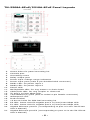
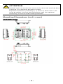
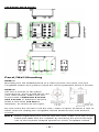
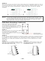
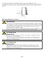
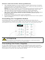
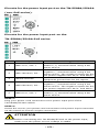
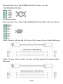
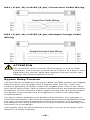
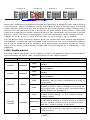
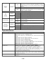
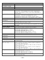
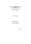
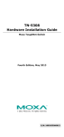
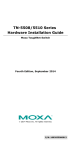
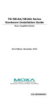
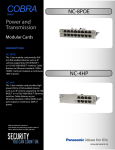
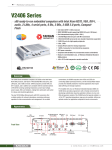
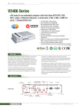
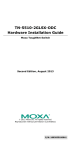
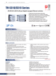
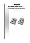
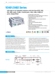
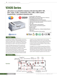
TN-5508A/5510A Series Hardware Installation Guide Moxa ToughNet Switch Second Edition, March 2015 2015 Moxa Inc. All rights reserved. P/N: 1802055080021 *1802055080021* Overview The ToughNet TN-5508A/5510A series M12 managed Ethernet switches are designed for industrial applications in harsh environments. The TN series switches use M12 connectors to ensure tight, robust connections, and guarantee reliable operation against environmental disturbances, such as vibration and shock. The wide 24 to 110 VDC with dual power input (non-PoE series) increases the reliability of your communications. The TN-5508A series includes PoE and non-PoE switches. • • TN-5508A series: 8 Fast Ethernet M12 ports. TN-5508A-8PoE series: 8 PoE Fast Ethernet M12 ports. The TN-5510A series also includes PoE and non-PoE switches. • • TN-5510A series: 8 Fast Ethernet M12 ports, supports additional 2 Gigabit ports located on the bottom of the unit, with or without bypass function. TN-5510A-8PoE series: 8 PoE Fast Ethernet M12 ports, supports additional 2 Gigabit ports located on the bottom of the unit, with or without bypass function. The -40 to 75°C operating temperature and IP54 rated waterproof enclosure allow deployment in harsh environments. The TN-5508A/5510A series Ethernet switches are compliant with EN50155/50121-3-2/50121-4 (railway applications) requirements, covering operating temperature, power input voltage, surge, ESD and vibration, making the switches suitable for a variety of industrial applications Package Checklist Your ToughNet TN-5508A/5510A switch is shipped with the following items. If any of these items is missing or damaged, please contact your customer service representative for assistance. • • • • • • • 1 Moxa ToughNet switch. Hardware installation guide. CD-ROM with user’s manual. Moxa product warranty statement. M12 to DB9 console port cable. 2 protective caps for console and relay output ports Panel mounting screws. Features Anti-Vibration Circular Connectors for Robust Links • • • • M12 D-coding 4-pin female connectors for Fast Ethernet 10/100BaseT(X) ports. M12 X-coded 8-pin female connectors for Gigabit Ethernet 10/100/1000BaseT(X) ports M12 A-coding 5-pin male connectors for console and relay output. M23 6-pin male connectors for power input. Isolated Power Inputs • Supports 24-110 VDC (16.8 to 137.5 VDC). -2- High Performance Network Switching Technology • • • • • • • • • • • • • • • • • • • • • IPv6 ready, certified by the IPv6 Logo Committee. IEEE 1588 PTP (Precision Time Protocol) for the precise time synchronization of networks. DHCP Option 82 for IP address assignment with different policies. EtherNet/IP and Modbus/TCP industrial Ethernet protocols supported. Turbo Ring and Turbo Chain (recovery time <20 ms @250 switches),and STP/RSTP/MSTP for network redundancy IGMP Snooping and GMRP for filtering multicast traffic from industrial Ethernet protocols. Port-based VLAN, IEEE802.1Q VLAN, and GVRP protocol to ease network planning. QoS (IEEE 802.1p/1Q and ToS/DiffServ) allows real-time traffic classification and prioritization. 802.3ad, LACP for optimum bandwidth utilization. TACACS+, SNMPv3, IEEE 802.1X, HTTPS, and SSH to enhance network security SNMP v1/v2c/v3 for different levels of network management. RMON for efficient network monitoring and proactive capability. Bandwidth management prevents unpredictable network status. Lock port allows access by only authorized MAC addresses. Port mirroring for online debugging. Automatic warning by exception through email, relay output. Automatic recovery of connected devices’ IP addresses. Line-swap fast recovery. LLDP for automatic topology discovery through network management software. Loop protection prevents network loops Configurable through Web browser, Telnet/Serial console, CLI, and Windows utility. Designed for Industry-specific Applications • • • • • • Two Gigabit Ethernet ports to meet high bandwidth requirements. Bypass relay option on the 2 Gigabit Ethernet ports ensure non-stop data communication in the event a switch stops working due to a power failure. EN 50155/50121-3-2/50121-4 compliant. -40 to 75°C operating temperature range. IP54 rugged high-strength case. Panel mounting or DIN-Rail mounting installation capability. Recommended Optional Accessories • • • • • • • CBL-M23(FF6P)Open-BK-100-IP67: 1-meter M23 to 6-pin power cable with IP67-rated female 6-pin M23 connector. CBL-M12D(MM4P)/RJ45-100 IP67: 1-meter M12-to-RJ45 Cat-5E UTP Ethernet cable with IP67-rated male 4-pin M12 D-coded connector. CBL-M12(FF5P)/OPEN-100 IP67: 1-meter M12-to-5-pin power cable with IP67-rated female 5-pin M12 A-coded connector. M12D-4P-IP68: Field-installable M12 D-coded screw-in connector, male 4-pin, IP68-rated. M12A-5P-IP68: Field-installable M12 A-coded screw-in connector, female 5-pin, IP68-rated. CAP-M12F-M: Metal cap for M12 female connector DK-DC50131: DIN-Rail mounting kit, 50 x 131 mm. -3- TN-5508A/5510A Panel Layouts 1. 2. 3. 4. 5. 6. 7. 8. 9. 10. 11. 12. 13. 14. 15. 16. 17. 18. 19. 20. 21. Model name. Screw holes for panel mounting kit. Console port. Grounding screw. Relay output port. Power input voltage range indication. Power input port (male 5-pin shielded M23 connector). PWR1 LED: for power input 1. PWR2 LED: for power input 2. FAULT LED. MSTR/HEAD LED: for ring master or chain head. CPLR/TAIL LED: for ring coupler or chain tail. TP port’s 10/100 Mbps LED. 10/100BaseT(X) port (M12 D-coded 4-pin female connector) Waterproof vent. Product label. 12 Screw holes for DIN-Rail mounting kit. E2 LED: Not used by the TN-5508A series. E1 LED: Not used by the TN-5508A series. Gigabit Ethernet port E1 (corresponding to port 9 in the TN-5510A User's Manual). Gigabit Ethernet port E2 (corresponding to port 10 in the TN-5510A User's Manual). -4- TN-5508A-8PoE/5510A-8PoE Panel Layouts 1. 2. 3. 4. 5. 6. 7. 8. 9. 10. 11. 12. 13. 14. 15. 16. 17. 18. 19. 20. 21. Model name Screw holes for panel mounting kit Console port Grounding screw Relay output port Power input voltage range indication Power input port (male 5-pin shielded M23 connector) PWR1 LED: for power input 1 PWR2 LED: for power input 2 FAULT LED MSTR/HEAD LED: for ring master or chain head CPLR/TAIL LED: for ring coupler or chain tail TP port’s 10/100 Mbps LED 10/100BaseT(X) port (M12 D-coded 4-pin female connector) Waterproof vent Product label 12 Screw holes for DIN-Rail mounting kit E2 LED: Down-side E2 Gigabit port's 10/100/1000 Mbps LED E1 LED: Down-side E1 Gigabit port's 10/100/1000 Mbps LED Gigabit Ethernet port E1 (corresponding to port 9 in the TN-5510A User's Manual) Gigabit Ethernet port E2 (corresponding to port 10 in the TN-5510A User's Manual) -5- ATTENTION DO NOT open or remove the vent (#15). Once the seal has been removed, the warranty becomes invalid. Exposed connectors (including 3, 5, and 14) when not in use must be tightly covered with protective caps (an optional accessory) to ensure IP54-rated protection. Mounting Dimensions (unit = mm) TN-5508A Series -6- TN-5508A-8PoE Series -7- TN-5510A Series -8- TN-5510A-8PoE Series Panel/Wall Mounting STEP 1: Mounting the TN-5508A/5510A to a wall requires 4 screws. Use the ToughNet switch as a guide to mark the correct positions of the 4 screws. STEP 2: Use the 4 screws in the panel mounting kit. If you would like to use your own screws, make sure the screw head is between 6.0 mm and 7.0 mm in diameter and the shaft is less than 4.0 mm in diameter, as shown at the right. Do not screw the screws in all the way—leave a space of about 2 mm to allow room for sliding the ToughNet switch between the wall and the screws. NOTE Before tightening the screws into the wall, make sure the screw head and shaft size are suitable by inserting the screw through one of the keyhole-shaped apertures of the ToughNet switch. -9- STEP 3: Once the screws are fixed in the wall, hang the ToughNet switch on the 4 screws through the large opening of the keyhole-shaped apertures, and then slide the switch downwards. Tighten the four screws for added stability. NOTE To provide greater protection from vibrations and shocks, use screws with shaft diameter between 6.0 mm and 7.0 mm, and fix the ToughNet switch onto the wall directly through the large opening of the keyhole-shaped apertures. DIN-Rail Mounting (optional) With the optional DIN-Rail mounting kit DK-DC50131 (must be purchased separately), you can mount the TN-5508A/5510A on a 35mm DIN-Rail. STEP 1: Use 12 screws (6 screws per plate) to attach the two DIN-Rail attachment plates to the rear panel of the switch. STEP 2: If the spring-loaded bracket is locked in place, push the recessed button to release it. Once released, you should feel some resistance from the spring as you slide the bracket up and down a few millimeters in each direction. STEP 3: Position the ToughNet switch onthe DIN-Rail, tilting to hook clamps over the top edge of the rail. STEP 4: Swing the switch down fully onto the DIN-Rail, until both clamps completely latch. - 10 - To remove the Moxa ToughNet Switch from the DIN-Rail, use a screwdriver to pull out the two spring-loaded brackets from the bottom until they are fixed in the “locked” position. Then reverse Step 3 and 4 above. Wiring Requirements WARNING Turn the power off before disconnecting modules or wires. The correct power supply voltage is listed on the product label. Check the voltage of your power source to make sure you are using the correct voltage. Do NOT use a voltage greater than what is specified on the product label. These devices must be supplied by a SELV source as defined in the Low Voltage Directive 2006/95/EC and 2004/108/EC. ATTENTION Safety First! Be sure to disconnect the power cord before installing and/or wiring your Moxa switch. This device has UL508 approval. Use copper conductors only, 75°C, and tighten to 4.5 pound-inches. For use in pollution degree 2 environments. ATTENTION Safety First! Observe all electrical codes dictating the maximum current allowable for each wire size. If the current goes above the maximum ratings, the wiring could overheat, causing serious damage to your equipment. - 11 - Please read and follow these guidelines: • • • • Use separate paths to route wiring for power and devices. If power wiring and device wiring paths must cross, make sure the wires are perpendicular at the intersection point. NOTE: Do not run signal or communications wiring and power wiring through the same wire conduit. To avoid interference, wires with different signal characteristics should be routed separately. You can use the type of signal transmitted through a wire to determine which wires should be kept separate. The rule of thumb is that wiring that shares similar electrical characteristics can be bundled together. Keep input wiring and output wiring separated. It is strongly advised that you label wiring for all devices in the system when necessary. Grounding the ToughNet Switch Grounding and wire routing help limit the effects of noise due to electromagnetic interference (EMI). Run the ground connection from the grounding screw to the grounding surface prior to connecting devices. ATTENTION This product is intended to be mounted to a well-grounded mounting surface such as a metal panel. Connecting the Power Supplies In non-PoE switches, the ToughNet TN-5508A/5510A series switches support two sets of power input—power input 1 and power input 2. The M23 6-pin male connector on the TN-5508A/5510A non-PoE switches’ front panel is used for the dual power inputs. - 12 - Pinouts for the power input port on the TN-5508A/5510A (non-PoE series). Pinouts for the power input port on the TN-5508A/5510A-PoE series Pin Description 1 PWR1 Live / DC + 2 PWR1 Neutral / DC - 3 Chassis Ground 4 PWR2 Neutral / DC - 5 PWR2 Live / DC + Usage Connect “PWR1 Live / DC +” to the positive (+) terminal when using a DC power source. Connect “PWR1 Neutral / DC -” to the negative (-) terminal when using a DC power source. The negative inputs for the two power supplies are N1/V- and N2/V-. Connect the “Chassis Ground” to the equipment ground bus for DC inputs. Connect “PWR2 Neutral / DC -” to the negative (-) terminal when using a DC power source. The negative inputs for the two power supplies are N1/V- and N2/V-. Connect “PWR2 Live / DC +” to the positive (+) terminal when using a DC power source. STEP 1: Plug your power cord connector to the power input port of the TN-5508A/5510A switch. STEP 2: Screw the nut on your power cord connector to the power input connector on the switch to ensure a tight connection. ATTENTION Before connecting the TN-5508A/5510A to the power input, make sure the power source voltage is stable. - 13 - ATTENTION Do not power on the TN-5508A/5510A before connecting the M23 connector. Connecting the Relay Outputs Each TN-5508A/5510A switch has two sets of relay outputs—relay output 1 and relay output 2.The M12 A-coded 5-pin male connector on the TN-5508A/5510A front panel is used for the two relay outputs. Use a power cord with an M12 A-coded 5-pin female connector to connect the relay contacts. You can purchase an M12 power cable from Moxa; the model number is CBL-M12 (FF5P)/OPEN-100 IP67. Pinouts for the relay output port on TN-5508A/5510A. N.C.: Not connected FAULT: The two sets of relay contacts of the M12 A-coded 5-pin male connector are used to detect user-configured events. The two wires attached to the fault contacts form an open circuit when a user-configured event is triggered. If a user-configured event does not occur, the fault circuit remains closed. Connecting the Data Lines 10/100BaseT(X) Ethernet Port Connection All TN-5508A/5510A models have 8 10/100BaseT(X) Ethernet ports (M12 D-coded 4-pin female connector). The 10/100TX ports located on the TN-5508A/5510A front panel are used to connect to Ethernet-enabled devices. Most users configure these ports for Auto MDI/MDI-X mode, in which case the port’s pinouts are adjusted automatically depending on the type of Ethernet cable used (straight-through or cross-over), and the type of device (NIC-type or HUB/Switch-type) connected to the port. In what follows, we give pinouts for both MDI (NIC-type) ports and MDI-X (HUB/Switch-type) ports. We also give cable wiring diagrams for straight-through and cross-over Ethernet cables. - 14 - Pinouts for the 10/100BaseT(X) Ports on the TN-5508A/5510A. Housing:shield Pinouts for the 10/100/1000BaseT(X) M12 (8-pin) Port M12 (4-pin, M) to M12 (4-pin, M) Cross-Over Cable Wiring M12 (4-pin, M) to M12 (4-pin, M) Straight-Trough Cable Wiring - 15 - M12 (4-pin, M) to RJ45 (8-pin) Cross-Over Cable Wiring M12 (4-pin, M) to RJ45 (8-pin) Straight-Trough Cable Wiring ATTENTION The protective cover must be fixed properly to ensure IP54 protection. Use a torque wrench set to a torque of 4 kgf-m when tightening the screws. Note that applying a larger torque may damage the plastic protective cover. Bypass Relay Function The TN-5510A-2GTXBP and TN-5510A-8PoE-2GTXBP models’ two Gigabit Ethernet ports are equipped with a bypass relay function. When the switch is operating normally, these two Gigabit ports work in the same way as the other ports. That is, frame ingressions are processed and then forwarded. In the event the switch stops working due to a power failure, the bypass relay function will be triggered to ensure non-stop data communication. The figure below illustrates the bypass relay function. For example, if Switch B loses power, then the two Gigabit ports will be bypassed through the relay circuit and the transmission line from Switch A to B and the transmission line from Switch B to C will interconnect automatically; this way there is no stoppage. The bypass relay function helps the network recover from single-node failures in a linear topology. - 16 - Switch A Switch B Switch C Switch D Bypassing With the maximum segment length of category 5 twisted-pair cable being 100 meters, cable length must be considered when designing a network that utilizes this function. For example, the total length of the cables from Switch A to B and from B to C must be no more than 100 meters. This way, if the two adjacent nodes (switch B and C for example) encounter a power failure, there will be no stoppage, provided that the total length of the cables A-to-B, B-to-C, and C-to-D are no more than 100 meters. The bypass relay function works best for networks with linear topologies. ToughNet™ switches with bypass relay function are not recommended to be used in networks that employ ring topologies because network loops may occur when redundancy protocols such as RSTP or TurboRing™ are applied. LED Indicators Several LED indicators are located on the ToughNet switch’s front panel. The function of each LED is described in the table below. LED Color PWR1 AMBER PWR2 AMBER FAULT RED MSTR/ HEAD GREEN State Description System LEDs Power is being supplied to power input ON PWR1. Power is not being supplied to power OFF input PWR1 Power is being supplied to power input ON PWR2. Power is not being supplied to power OFF input PWR2. When the corresponding PORT alarm is ON enabled, and a user-configured event is triggered. When the corresponding PORT alarm is enabled and a user-configured event is OFF not triggered, or when the corresponding PORT alarm is disabled. When the TN switch is either the Master ON of this Turbo Ring, or the Head of this Turbo Chain. When the TN switch is Ring Master of this Turbo Ring and the Turbo Ring is broken, Blinking or it is Chain Head of this Turbo Chain and the Turbo Chain is broken. When the TN switch is neither the Master of this Turbo Ring, nor the Head of this OFF Turbo Chain. - 17 - When the TN switch enables the coupling function to form a back-up path in this Turbo Ring, or it is the Tail of this Turbo Chain. Blinking When Turbo Chain is down. When the TN switch disables the coupling OFF function of Turbo Ring, or it is not the Tail of the Turbo Chain. Ports LEDs ON TP port’s 10 Mbps link is active. Blinking Data is being transmitted at 10 Mbps. OFF TP port’s 10 Mbps link is inactive. ON TP port’s 100 Mbps link is active. Blinking Data is being transmitted at 100 Mbps. OFF TP port’s 100 Mbps link is inactive. Power is being supplied to a Powered ON Device (PD) Power is not being supplied to a Powered OFF Device (PD) ON TP port’s 10 or 100 Mbps link is active. Data is being transmitted at 10 or 100 Blinking Mbps. OFF TP port’s 10 or 100 Mbps link is inactive. ON TP port’s 1000 Mbps link is active. Blinking Data is being transmitted at 1000 Mbps. OFF TP port’s 1000 Mbps link is inactive. ON CPLR/ TAIL TP (10/ 100M) PoE Ports E1/E2 (10/100/ 1000M) GREEN AMBER GREEN AMBER AMBER GREEN Specifications Technology Standards Protocols MIB Flow Control IEEE 802.3 for 10BaseT IEEE 802.3u for 100BaseT(X) IEEE 802.3ab for 1000BaseT(X) (TN-5510A series only) IEEE 802.3x for Flow Control IEEE 802.1D for Spanning Tree Protocol IEEE 802.1w for Rapid STP IEEE 802.1Q for VLAN Tagging IEEE 802.1s for Multiple Spanning Tree Protocol IEEE 802.1p for Class of Service IEEE 802.1X for Authentication IEEE 802.3ad for Port Trunk with LACP IGMP v1/v2 device, GMRP, GVRP, SNMP v1/v2C/v3, DHCP Server/Client, DHCP Option 66/67/82, BootP, TFTP, SNTP, SMTP, RARP, RMON, HTTP, HTTPS, Telent, SSH, Syslog, LLDP, IEEE 1588 PTP v2, IPv6, NTP Server/Client, EtherNet/IP, Modbus/TCP MIB-II, Ethernet-like MIB, P-BRIDGE MIB, Q-BRIDGE MIB, Bridge MIB, RSTP MIB, RMON MIB Group 1, 2, 3, 9 IEEE802.3x flow control, back pressure flow control - 18 - Switch Properties Priority Queues Max. Number of Available VLANs VLAN ID Range IGMP Groups Interface Fast Ethernet Gigabit Ethernet Console Port System LED Indicators Port LED Indicators 4 64 VID 1 to 4094 256 Front cabling, M12 D-coded 4-pin female connector, 10/100BaseT(X) auto negotiation speed, F/H duplex mode, and auto MDI/MDI-X connection Down cabling, M12 X-coded 8-pin female connector, 10/100/1000BaseT(X) auto negotiation speed, F/H duplex mode, auto MDI/MDI-X connection, and bypass relay option M12 A-coding 5-pin male connector PWR1, PWR2, FAULT, MSTR/HEAD, CPLR/TAIL 10/100M (Fast Ethernet port), 10/100/1000M (Gigabit Ethernet port), PoE Alarm Contact Two relay outputs in one M12 A-coding 5-pin male connector with current carrying capacity of 1 A @ 30 VDC Power Requirements Input Voltage WV: 24-110 VDC (16.8 to 137.5 VDC) Max. Input Current TN-5508A Series: 0.28 A TN-5510A-2GTX Series: 0.52 A TN-5510A-2GTXBP Series: 0.56 A TN-5508A-8PoE Series: 7.6 A TN-5510A-8PoE-2GTX Series: 7.85 A TN-5510A-8PoE-2GTXBP Series: 7.9 A Connection M23 6-pin male connector Overload Current Present Protection Reverse Polarity Present Protection Physical Characteristics Housing Metal, IP54 protection (with protective caps on unused ports) Dimensions TN-5508A Series: (W H D) 185 x 175.8 x 76 mm (7.28 x 6.92 x 2.99 in) TN-5508A-8PoE Series: 185 x 175.8 x 115 mm (7.28 x 6.92 x 4.53 in) TN-5510A Series: 185 x 180.9 x 76 mm (7.28 x 7.12 x 2.99 in) TN-5510A-8PoE Series: 185 x 180.9 x 115 mm (7.28 x 7.12 x 4.53 in) Weight TN-5508A Series: 1,610 g TN-5510A Series: 1,711 g TN-5508A-8PoE Series: 2,383 g TN-5510A-8PoE Series: 2,551 g Installation Panel mounting, DIN-Rail mounting (with optional kit) - 19 - Environmental Limits Operating -40 to 75°C (-40 to 167°F) Temperature Storage Temperature -40 to 85°C (-40 to 185°F) Operating Humidity 5 to 95% (non-condensing) Regulatory Approvals Safety UL/cUL 508 Rail Traffic EN50155, EN50121-3-2, EN50121-4 EMI FCC Part 15, CISPR (EN55022) class A EMS EN61000-4-2 (ESD), level 3 EN61000-4-3 (RS), level 3 EN61000-4-4 (EFT), level 3 EN61000-4-5 (Surge), level 3 EN61000-4-6 (CS), level 3 EN61000-4-8 Shock IEC61373 Freefall IEC60068-2-32 Vibration IEC61373 Note: Please check Moxa’s website for the most up-to-date certification status. WARRANTY 5 years Details: See www.moxa.com/warranty Technical Support Contact Information www.moxa.com/support Moxa Americas: Toll-free: 1-888-669-2872 Tel: 1-714-528-6777 Fax: 1-714-528-6778 Moxa China (Shanghai office): Toll-free: 800-820-5036 Tel: +86-21-5258-9955 Fax: +86-21-5258-5505 Moxa Europe: Tel: +49-89-3 70 03 99-0 Fax: +49-89-3 70 03 99-99 Moxa Asia-Pacific: Tel: +886-2-8919-1230 Fax: +886-2-8919-1231 - 20 -