1
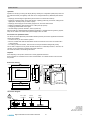
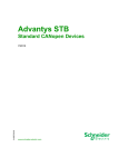
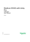
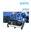
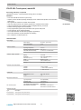
Product data sheet
93.070
EY-OP 250: Touch-panel, modu250
How energy efficiency is improved
SAUTER EY-modulo 2 – tried and tested technology with a new design
Features
• Part of the SAUTER EY-modulo 2 system family
• Graphic, pressure-sensitive operating and display unit for network-wide operation of the automation
stations (AS)
• Menu-guided user interface to visualise ASs and plants
• Alarm lists, data point lists, time switching programmes, calendars and trend data
• Change specified setpoints, positioning values and digital positioning commands
• Edit time switching programmes and calendars
• Freely-programmable graphic plant presentations with dynamic data points
• Access rights with users created individually
• Can be parameterised via CASE Suite (languages, applications)
• RJ-45, DB-9 interfaces for parameterisation and updating
• RJ-11 interface for novaNet system bus
EY-OP250F001
Technical data
Power supply
Power supply
85...250 V~ (48...62 Hz)
Power consumption
≤7W
Operating temperature
0...45 °C
Storage and transport temperature
–25...70 °C
Admissible ambient humidity
10...80% rh, no condensation
Display
5.7 inches
Resolution
320 × 240 pixels (QVGA)
Active area (W x H)
140 × 105 mm
Touch
Resistive, 4-wire
Ambient conditions
Indicators, display, operation
Illumination
Time-controlled cut-off
Memory
8 MB flash, 8 MB RAM
novaNet
1× RJ-11 socket
Ethernet
1 × RJ-45 socket (10BaseT)
EIA-232
1 × DB9 connector
Dimensions W x H x D
204 × 156 × 46 mm
Weight
1 kg
Type of protection
IP 20 (EN 60529)
Protection class
I (EN 60950-1)
Interfaces and communication
Construction
Standards and directives
CE conformity as per
Environment class
3K3 (IEC 60721)
Low-voltage directive 2006/95/EC
EN 60950-1
EMC directive 2004/108/EC
EN 61000-6-1, EN 61000-6-2,
EN 61000-6-4, EN 55022 Class A
Overview of types
Type
Description
EY-OP250F001
Touch-panel, colour (256 colours)
EY-OP250F002
Touch-panel, monochrome (b/w)
Right of amendment reserved © 2015 Fr. Sauter AG
3.1
1/3
93.070
Product data sheet
Accessories
Software
Type
Description
GZS100F599
CASE Tools CD, latest version (CASE TPC, CASE HWC, CASE Sun, novaNet292 SW ...)
7001064001
User manual, German
Connecting cables
Type
Description
0367862001
Automation station to modu250: 1.5 m
0367862002
Automation station to modu250: 2.9 m
0367862003
Automation station to modu250: 6.0 m
General information
Type
Description
0374494001
Stylus set for modu250
0374509001
Connector, 3-pin, packaged
0374515001
Set to extend degree of protection, IP 65 (incl. seal, 0374680001)
0374680001
Seal, single (for set 0374515001)
Additional information
Fitting instructions
P100002332
Declaration on materials and the environment
MD 93.070
Description of operation
The modu250 touch-panel is used for the graphical display, navigation and operation of the automation station (AS) and its plants on site.
Intended use
This product is only suitable for the purpose intended by the manufacturer, as described in the “Description of operation” section.
All related product documents must also be adhered to. Changing or converting the product is not admissible.
Engineering notes
Fitting and power supply
The touch-panel is mounted on a top-hat rail or directly on the front of a control cabinet.
The power supply with 85…240 V AC is connected via a pluggable connection terminal with an earth
conductor. Connection may only be performed when the system is disconnected from the electrical
supply.
When commissioning the device, you must remove the protective film on the front, otherwise the
readability of the display and the touch function may be negatively affected.
The communication wiring must be carried out correctly and in accordance with standards
EN 50174-1, -2 and -3. Communication wires must be kept separate from other live wires.
Data line
Through direct connection to the novaNet network (RJ-11 socket), it is possible to access all connected ASs.
The number of communicating AS stations per touch-panel must not be greater than 100.
Every touch-panel in the novaNet network requires a unique address between 31744 and 31799
(comparable with PC subscribers); the factory setting is 31999.
If the touch-panel is connected directly to the moduFlex universal controller via point-to-point module
0374448001, the max. admissible cable length is 6 m.
Special standards such as IEC/EN 61508, IEC/EN 61511, IEC/EN 61131-1 and -2 were not taken into
account. Local requirements regarding installation, usage, access, access rights, accident prevention,
safety, dismantling and disposal must be taken into account. Furthermore, the installation standards
EN 50178, 50310, 50110, 50274, 61140 and similar must be observed.
LED indicators
Above the display of the touch-panel there are LEDs displaying the following information:
• The middle LED flashes green if the power supply is correct.
• The LED on the outer left flashes red when an alarm is active in an opened application.
2/3
3.1
Right of amendment reserved © 2015 Fr. Sauter AG
93.070
Product data sheet
Operation
Operation is entirely by touching the display directly, whereby the configuration (data points) of the AS
are read automatically in Plug&Play mode and can be managed without any additional parameterisation:
• Displaying and selecting the applications (direct access to the automation stations)
• Displaying measured values, alarms and statuses, outputting positioning commands, analogue and
digital (max. 200 data points per station or plant)
• Displaying and changing time and holiday programmes, as well as date and time
• Reading and displaying historical data (max. 3 data points per picture)
• Configuring password and access rights
• General settings (contrast, calibration, reboot, system info)
With the CASE TPC (GZS100F599) parameterising software, a separate interface (pictures, graphics,
lists) can be created. This makes user-specific displays easier to create.
Connections for parameterisation
The RJ-45 connection (Ethernet) and the DB9 interface (EIA-232) are used for application downloads
and firmware updates.
• The device is only for TN-S network systems.
• Ethernet, novaNet and COM are SELV/PELV electrical circuits and must not be connected to ELV
or TNV networks.
• For setting up fixed connections, there must be an easily accessible isolating facility nearby.
This is class A equipment. It may cause wireless interference in residential premises; in this case, the
operator may be requested to implement appropriate measures.
For further information, see the fitting instructions.
Disposal
When disposing of the product, observe the currently applicable local laws.
More information on materials can be found in the Declaration on materials and the environment for
this product.
Dimension drawing
2
138
186
1
Connection diagram
RJ 11 6/6
novaNet
230 V~
<7W
RJ 45
Ethernet
DB 9
RS232
N L
Fr. Sauter AG
Im Surinam 55
CH-4016 Basel
Tel. +41 61 - 695 55 55
www.sauter-controls.com
Right of amendment reserved © 2015 Fr. Sauter AG
3.1
3/3