1
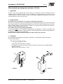
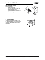
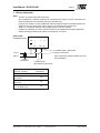
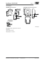
GA-P135-024
Direct coupled, non-spring return actuators, 135 in-lb
User Manual
November, 2003
ISO 9001
Phone (858) 578-7887 & (888) GO INTEC
Fax (858) 578-4633 & (888) FX INTEC
INTEC Controls, Inc., P.O. Box 12506, La Jolla, CA 92039
www.inteccontrols.com
Specification subject to change without notice
Printed in Germany
User Manual - GA-P135-024
Page 3
page
1 Application ............................................................................................................................4
2 Safety remarks......................................................................................................................4
3 Installation.............................................................................................................................4
4 Position indication................................................................................................................5
5 Wiring configuration ............................................................................................................6
6 Function and signal selection.............................................................................................7
7 Connection of positioner FGEB..........................................................................................7
8 Parallel control of two or more actuators ..........................................................................8
9 Dimensions ...........................................................................................................................9
10 Ordering information............................................................................................................9
11 Specifications .....................................................................................................................10
12 Positioners ..........................................................................................................................11
Phone (858) 578-7887 & (888) GO INTEC
Fax (858) 578-4633 & (888) FX INTEC
INTEC Controls, Inc., P.O. Box 12506, La Jolla, CA 92039
www.inteccontrols.com
Specification subject to change without notice
Printed in Germany
User Manual - GA-P135-024
Page 4
Direct coupled, non-spring return actuators, 135 in-lb
1
Application
Actuators to be easily installed by direct shaft mounting on air dampers, shutters and butterfly valves in
ventilation and air conditioning systems. Can be controlled by any compatible electric or electronic analog
controller DDC/PLC control or automation system. The actuators should be mounted indoors in a dry environment, relatively free from corrosive fumes.
2
Safety remarks
The actuators are not suitable for use in explosive atmospheric applications!
All service to the actuators (mounting, electrical connection, retrofitting and repair) must be carried out with the
power supply disconnected. The electrical connection must be done by a trained and competent person considering the wiring diagrams, local and national regulations. Use copper twisted conductors only. Provide disconnect and overload protection if necessary.
This actuator may only be operated by 24 VAC/VDC!
The transformer must be sized according to technical data of the actuator (see section 11). Electronics and
controllers must be powered from a separate transformer when controller power is full-wave rectified. Otherwise
the controller or the actuator may be damaged.
Always read the controller installation instructions before making any connection!
3
Installation
Direct mounting with V-bolt clamp to the damper shaft (diagr. 1) and fixing with enclosed anti-rotation
mounting bracket (diagr. 2).
Shaft: Ø 5/16" to 5/8" (Ø 8 - 16 mm)
5/16" to 15/32" ( 8 - 12 mm)
•
•
•
Turn the damper until the blades are closed
Disengage the gears by pressing the red button and rotate the clamp until the switching position
indication shows 90°
Tighten the nuts on the clamp (4 - 6 ft-lb)
diagram 1
Phone (858) 578-7887 & (888) GO INTEC
Fax (858) 578-4633 & (888) FX INTEC
INTEC Controls, Inc., P.O. Box 12506, La Jolla, CA 92039
www.inteccontrols.com
diagram 2
Specification subject to change without notice
Printed in Germany
User Manual - GA-P135-024
Page 5
If the damper shaft is too short:
Proceed as in diagram 3:
•
•
•
•
Remove the snap ring
Pull out the V-bolt clamp assembly from
the actuator towards outside
Push the V-bolt clamp assembly from the
opposite face
Refit the snap ring
diagram 3
Position indication
°
90
0
m(
)m
40
20 30
60 45 30 15
10
(m
m)
Phone (858) 578-7887 & (888) GO INTEC
Fax (858) 578-4633 & (888) FX INTEC
INTEC Controls, Inc., P.O. Box 12506, La Jolla, CA 92039
www.inteccontrols.com
0°
The damper position can be seen from the scale
0° - 90°. A remote display can be connected to the
servomotors with modulating control (see wiring
configuration).
75
4
Specification subject to change without notice
Printed in Germany
User Manual - GA-P135-024
5
Page 6
Wiring configuration
Notes:
• Actuators are provided with color coded wires.
• Observe polarity on secondary of transformers. All common and signal (-) must be connected in line.
Incorrect polarity can cause controller damage or operation error.
• Long wire runs requires a 4-wire configuration (connect common for power and control signal at the
actuator or close by). Greater than a 0.2 V drop must be avoided for any common wire.
• Always use a separate transformer when controller power is full-wave rectified.
• Controller and actuators must have separate transformers for paralleled multi-actuator application.
• Provide overload protection for line voltage and disconnect as required.
GA-P135-024
Proportional control
com
+
Y
U
~
blk
red
wht grn
(+) U, Feedback signal*, (0)2-10 VDC
(-) or supply of 10/15 VDC
Line L2
Volts L1
24 VAC
Transformer
Multiple actuators
(maximum quantities)
(-) (+)
* Signal can provide position indication or masterslave applications.
Y, Control signal
(0)2-10 VDC, or (0)4-20 mA
GA-P135-024
Proportional
Stacking (torque is additive)
4
Parallel connection
(0)2-10 VDC
20
Parallel connection
(0)4-20 mA
10
Master-slave
via U, feedback signal
10
Phone (858) 578-7887 & (888) GO INTEC
Fax (858) 578-4633 & (888) FX INTEC
INTEC Controls, Inc., P.O. Box 12506, La Jolla, CA 92039
www.inteccontrols.com
Specification subject to change without notice
Printed in Germany
User Manual - GA-P135-024
6
Page 7
Function and signal selection
L/R selector (built-in actuator cover)
Functional switch
Select
R
L
Angle of rotation
CW/0-90°
”with increase of
CCW/90-0°
control signal”
Signal selector
(dip switch built-on printed circuit-board)
ON
OFF
1
2*
3
4
5
6
7
8
Dip switch setting
Y, control signal:
• 0-10 VDC
• 2-10 VDC
• 0-20 mA
• 4-20 mA
Off
On
1, 4
4
1
-
1
4
1, 4
U, feedback signal
or VDC supply:
• 0-10 VDC
• 2-10 VDC
• 10 VDC
• 15 VDC
3,
7,
3,
3,
5, 6
3, 5, 6
5, 7
8
7, 8
8
6, 8
5, 6, 7
Note:
Any combinations between Y & U are
possible.
Factory set: Off = 1, 3, 4, 7, 8
On = 2*, 5, 6
(Y & U = 0-10 VDC)
Switch 2*: Must stay in ”On” position to allow
L/R selector to operate
7
Connection of positioner FGEB
GA-P135-024
Proportional control
com
+
Y
Positioner
FGEB
U
~
blk
red
wht grn
1
2
3
15 VDC
0-10 VDC
Line L2
Volts L1
24 VAC
Transformer
Phone (858) 578-7887 & (888) GO INTEC
Fax (858) 578-4633 & (888) FX INTEC
INTEC Controls, Inc., P.O. Box 12506, La Jolla, CA 92039
www.inteccontrols.com
4
Attention:
The dip switches of the signal
selector must stay in correct
position.
input signal 0-10 VDC
output signal 0-10 VDC
Notes:
•
Provide overload protection
and disconnect as required.
•
Always use a separate
transformer when controller
power is full-wave
•
Set reversing switch L/R as
required.
Specification subject to change without notice
Printed in Germany
User Manual - GA-P135-024
8
Page 8
Parallel control of two or more actuators
Notes:
• Provide overload protection and disconnect as required.
• Always use a separate transformer when controller power is full-wave.
• Set reversing switch L/R as required.
GA-P135-024
Proportional control
com
+
Y
com
U
~
blk
Y, Control signal
red
+
Y
U
~
blk
wht grn
red
wht grn
(+)
(-)
U
U
Line L2
Volts L1
24 VAC
Transformer
U, Feedback signal
Attention:
•
Observe polarity on secondary of transformers.
•
Connect all actuator black wires to line of transformer and all red wires to the other leg of the
transformer and all white wires together to “Y“ of control signal.
Incorrect polarity can damage controller or cause an error in operation!
Before starting the operation, all electrical and mechanical functions have to be checked!
The actuator and the controller must be powered by separate transformer!
Phone (858) 578-7887 & (888) GO INTEC
Fax (858) 578-4633 & (888) FX INTEC
INTEC Controls, Inc., P.O. Box 12506, La Jolla, CA 92039
www.inteccontrols.com
Specification subject to change without notice
Printed in Germany
User Manual - GA-P135-024
9
Page 9
Dimensions
1.44
[36.61]
2.40
[61.00]
0.83
[21.05]
0.24
[6.00]
0.04
[1.00]
0.71
[18.13]
0.118
[3.00]
0.47
[12.00]
0.79
[20.00]
1.20
[30.60]
1.66
[42.20]
disengage
button
0.41
[10.50]
8" ]
5/ .00
Ø 16
[Ø
3.82
[97.00]
90
∞
5
60 45 30 1
2.95
[75.00]
75
inches [mm]
M0.20
[5.00]
0∞
5.51
[140.00]
Note:
Anti-rotation mounting
bracket supplied
w/actuator
10 Ordering information
GA-P135-024
Standard
Phone (858) 578-7887 & (888) GO INTEC
Fax (858) 578-4633 & (888) FX INTEC
INTEC Controls, Inc., P.O. Box 12506, La Jolla, CA 92039
www.inteccontrols.com
Specification subject to change without notice
Printed in Germany
User Manual - GA-P135-024
Page 10
11 Specifications
Control
Input signal
Input impedance
Feedback signal
Electrical
Power supply
Over voltage
Power consumption
Performance
Torque
Damper size
Angle of rotation
· CCW(L) and CW(R)
Rotation time
Power failure
Position indicator
Synchronization
Overload protection
Proportional
(0)2-10 VDC,
or (0)4-20 mA,
switch selectable
100 kΩ
(0)2-10 VDC
or for use as constant
power supply 10/15 VDC
0.5 A (see section 6)
24 VAC/VDC ± 20%,
50/60 Hz
Up to 40 V, max. 5 sec.
5.5 W (7.0 VA)
Physical
Enclosure
· cover
· base
· color
· protection
Mounting position
Anti-rotation bracket
Stacking/paralleling
Clamp connection to
· round shaft
· square shaft
Wire connection
135 in-lb (15 Nm)
Up to 34 sq. ft. (3 m2)
0-95°/95-0°, selectable
L/R selector, built-in
actuator cover
40 to 80 sec/0-90°
Stays in last position of
operation
0-90° and adj. visual
indicator
± 1%
Electronic throughout
rotation
Built-in disengage button
DC motor
Max. 40 dB(A)
· option, on request
Wire size
Conduit connector
Dimensions
Weight
Manufacturing
Listings/Approvals
Warranty
Manual override
Motor type
Noise level
Environmental
Permissible ambient
· working temperature -22°F to 122°F
(-30°C to 50°C)
· storage temperature -40°F to 176°F
(-40°C to 80°C)
· humidity
5-95% RH, non-condensing
Phone (858) 578-7887 & (888) GO INTEC
Fax (858) 578-4633 & (888) FX INTEC
INTEC Controls, Inc., P.O. Box 12506, La Jolla, CA 92039
www.inteccontrols.com
ABS, UL 94-5V
PA 6.6
Grey and black
NEMA 2
Any position
Included w/actuator
Refer to table
“Multiple Actuators”
Ø 5/16" to 5/8"
(8 to 16 mm)
5/16" to 15/32"
(8 to 12 mm)
3 ft. (0.9 m) appliance
cable, color coded
Plenum rated cable
18 AWG (0.75 mm2)
1/2", built-in
5.51 x 2.95 x 2.28 in.
(140 x 75 x 58 mm)
1.6 lbs. (0.7 kg)
ISO 9001 certified
CE
UL and CSA
Five-year material and
workmanship
(Two-year standard,
three-year conditional)
Specification subject to change without notice
Printed in Germany
User Manual - GA-P135-024
Page 11
12 Positioners
1.5354
[39.00]
80
100
1.8898
[48.00]
40
60
80
% NE
U
GR
R
1.0236
[26.00]
% NER
U
GR
60
0
Ø 0.133 [Ø 3.4]
0.2362
[6.00]
0.2362
[6.00]
20
0
40
2.7559
[70.00]
0.039...0.196
[1...5 mm]
1.8898
[48.00]
20
FGEB-AB-4 with housing surface mount
100
FGEB-EB-4 panel flush mount
0.2362
[6.00]
0.2362
[6.00]
2.7559
[70.00]
1.063
[27.00]
Ø 0.315 [Ø 8]
0.5512
[14.00]
0.5512
[14.00]
1.8504
[47.00]
inches [mm]
The positioner will be supplied with 15 VDC from
the actuator.
Control voltage 0-10 VDC
Wiring diagram see section 7
Phone (858) 578-7887 & (888) GO INTEC
Fax (858) 578-4633 & (888) FX INTEC
INTEC Controls, Inc., P.O. Box 12506, La Jolla, CA 92039
www.inteccontrols.com
Specification subject to change without notice
Printed in Germany
Phone (858) 578-7887 & (888) GO INTEC
Fax (858) 578-4633 & (888) FX INTEC
INTEC Controls, Inc., P.O. Box 12506, La Jolla, CA 92039
www.inteccontrols.com
Specification subject to change without notice
Printed in Germany