Transcript
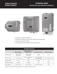
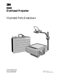
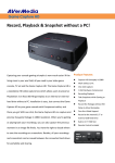
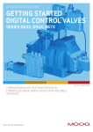
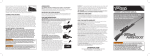
UTG NEW GEN 3X magnifier
MODEL NO.: SCP-MF3WQ
Low Profile Configuration with Mounting Deck Only
Leapers, Inc.
Proudly Presents
UTG FLIP-TO-SIDE
3X MAGNIFIER
MODEL NO.: SCP-MF3WQS
Medium Profile Configuration with Flip-to-Side QD Mounting Deck
Objective Lens
Objective Lens
Dioptric Adjustment
MUO006011104
Dioptric Adjustment
UTG
OPTICS
magnifiers
A. Specifications
Flip-to-Side QD
42mm
Mounting Deck
(Patent D672,839)
QD Lever Lock
(Patent: 8397421)
QD Lever Lock
(Patent: 8397421)
30mm
UTG FLIP-TO-SIDE 3X W/E MAGNIFIER
Medium Profile Configuration with Riser & Mounting Deck
Mounting
Objective Lens
Deck
Riser
scopes
DOT SIGHTS
Windage
Dioptric Adjustment
Objective Diameter
25mm
Field of View
9°
Exit Pupil Diameter
8.7mm
Eye Relief
51mm
Dioptric Adjustment
+/- 1 D
Tube Length
102mm
►►
Dioptric
Adjustment
►►
QD Lever Lock
(Patent: 8397421)
1 of 8
Coil Erector Return Spring
System for Guaranteed Zero
40mm
QD Lever Lock
(Patent: 8397421)
Flip-to-Side QD
Mounting Deck
(Patent D672,839)
2 of 8
42mm
►►
►►
Weight
SCP-MF3WQ : 260g
SCP-MF3WQS : 280g
SCP-MF3WQS : 335g
Lens Coating
Broadband Multi-layer
Compatible Rail
Picatinny/Weaver
•
Completely sealed and nitrogen filled to eliminate
risk of water ingress and fogging.
Multi Layer Lens
Transmission
Coating
for
Optimum
Light
•
Unique high tech lens coating applications ensure
much superior light transmission and optimize
optical performance.
•
Multi layer coatings allow for maximum utilization of
all ambient light to optimize resolution and clarity.
3X Magnification and Optic Enhancer for Most Dot
Sights
•
•
Ideal profiles for low profile applications that are
close to the bore or medium profile applications for
co-witnessing with iron sights.
Built-in corrective lens system to turn a glaring dot
3 of 8
•
Low profile quick detachable mount with adjustable
positions for optimal eye relief.
•
A smart riser raises the center height with adjustable
positions for further eye relief adjustment.
Innovative and Solid Flip-to-Side Design for Tactical
Applictions (SCP-MF3WQS, SCP-MF3WEQS)
•
Precision machined to exact tolerances from
aircraft-grade aluminum alloy for maximum
strength.
Magnified view through a sharp dot sight provides
an instant improvement on accuracy without any
compromises.
Versatile and Dependable Quick-detach Mounts for a
Wide Variety of Applications (SCP-MF3WQ)
•
•
TOTAL SOLUTION TO YOUR NEEDS
-COMMITMENT TO BEST QUALITY, BEST VALUE AND BEST SERVICE-
www.LEAPERS.com
32700 Capitol Street, Livonia, MI 48150, U.S.A.
Tel:(734)542-1500
Fax:(734)542-7095
Email:[email protected]
•
•
Precision Machined Parts
MODEL NO.: SCP-MF3WEQS
Elevation
3X
B. Major Features:
►► Rock Solid Robust Construction with High Quality
Medium Profile Configuration with Flip-to-Side QD Mounting Deck
and Windage/Elevation Adjustment
Objective Lens
to the perfect dot when used with a dot sight.
Magnification
At vertical position, medium profile to perfectly
co-witness with dot sights and AR iron sights,
providing 3X magnification for accurate aiming.
At flip-over position, clear the view for quick aiming
with dot sight only.
Easy one-hand switch
between two positions,
and solid locking in each
position with no wobbling
under recoil.
C. Mounting the Magnifier:
Fig 1.
CAUTION: Always ensure your
rifle is UNLOADED, UNCOCKED and, where applicable,
the safety catch is applied before fitting the scope. Practice
safe handling procedures at all times.
1.
Follow proper installation procedures to install your dot
sight on the rifle.
2.
For SCP-MF3WQ and SCP-MF3WEQS, the magnifier
comes with a low profile QD mount and a versatile riser.
Use the mount only or both mount and riser to match
your dot sight center height.
3.
Hold the magnifier behind the dot sight over the rifle at
your natural shooting position. Locate a proper position
for the magnifier so you can achieve a full field of view.
The low profile QD mount works with or without the riser
to offer adjustable positions for optimal eye relief shown
in Fig 1. It may require adjustment of the dot sight
position.
4 of 8
4.
For SCP-MF3WQS/SCP-MF3WEQS, go to Step 5.
For SCP-MF3WQ, based on your selection in Step 2,
attach the mount/riser as follows:
5.
• For QD Mount Only:
The mount comes with
3 locking holes allowing
space adjustment to
achieve optimal eye
relief. The mount can
be used bi-directionally
per your preference.
Fig 2.
Locate two set screws
and install a spring washer onto each screw. Based on
your eye relief preference in Step 3, select two holes on
the QD mount, fit the mount against the mating base on
the magnifer, and align the mount holes with the magnifer
holes. Install and fasten the set screws to fully secure the
mount as shown in Fig 2.
a. Turn the Cam Lever toward its
unlocked position as shown in
Fig 4. Place the QD mount on
the Picatinny rail at the desired
position. Make sure to seat the
cross bolt into a selected slot.
II. Install QD Mount: Based on your eye relief
preference in Step 3, select two holes on the QD
mount and align them to the mating holes on the
extruded part of the riser. Install and fasten the
remaining two set screws to fully secure the mount as
shown in Fig 3.
5 of 8
Fig 4.
c. Use the included Allen wrench to adjust the hex screw at
the side of the cam for proper tension and fit against the
rail. Adjust clockwise to increase the tension and tighten
the clamping width. Adjust counter-clockwise to decrease
the tension and increase the clamping width.
This configuration offers many different options from the
bi-directional mounting feature for both the QD mount
and the riser. The riser can be installed in either direction
depending on your preference. The same for the QD
mount. (NOTE: Figures included only show one example
direction.) Locate four set screws and install a spring
washer onto each screw.
d. The optimal tension is achieved when the side plate first
makes contact with the Picatinny rail while the Cam Lever
still has enough travel left for you to securely snap into its
locking position. Once you achieve the optimal tension,
push the Cam Lever all the way for a positive lock onto
the rail. You may repeat Step c and d if needed to find
the best clamping tension and locking position for your
mount.
D.
Fig 6.
Fig 5.
b. Turn the Cam Lever toward the locking position to begin
locking the QD mount on the rail, but do not complete the
locking motion, leaving some travel distance to allow for
adjustment.
• For QD Mount with Riser: I. Install Riser: Align
the riser to the mating
base on the magnifier
based on the direction
suitable for your
application. Install and
Fig 3.
fasten two set screws
to fully secure the riser as shown in Fig 3.
Align and install the magnifier onto the Picatinny rail with
the position selected in Step 3. Follow instructions below
to adjust for optimal tension
for quick detach, locking and
unlocking.
NOTE: Different individuals will have different eye focus
which will result in different diopter setting. A person will
use different diopter settings with or without eye glasses.
The repeating process below may cause eye strain and
contribute to parallax error. It will help if you can briefly look
away from the eye piece and then look back through it.
1.
Aiming your dot sight/magnifier at a distant target.
2.
Slightly rotate the focus ring until you have the sharpest
image as shown in Fig 7.
F. Care and Maintenance:
Fig 7.
Take care not to drop or
knock the magnifying scope once it is zeroed.
e. Now your QD Cam Lever is set for quick detach
operations. You may regularly inspect and adjust the
tension for best fit.
2.
Maintain the metal surface of the magnifying scope by
removing any dirt or sand with a soft brush so as to avoid
scratching the finish.
Switch Between Vertical/Flip-over Positions (for SCPMF3WQS/SCP-MF3WEQS):
3.
Wipe the lens with a clean flannel cloth to keep it clean
and dry. In order to avoid scratching the glass, ensure
both the lens and cloth are clean. Do not use finger or
finger nail to touch/clean lenses.
4.
Store the magnifying scope in a cool dry place when not
in use. Be careful to avoid contact with acid, alkaline or
corrosive chemicals.
II. Rotate the magnifier clockwise till the hinge component
is locked, so that your view is not obstructed as showing
in Fig 6.
6 of 8
Do not attempt to lubricate any part of the magnifying
scope.
6.
Do not disassemble the magnifying scope. Do not loosen
or remove screws or parts. Any such or similar actions will
void the warranty.
CAUTION: Viewing the sun can cause serious eye injury.
Never look directly into the sun with this or any scope.
E. Adjusting Focus / Diopter Setting:
1.
I. Pull the magnifier back towards you allowing the pins
inside the hinge component to be unlocked as shown in
Fig 5.
5.
7 of 8
G. Lifetime Manufacturer’s Warranty
Warranty against material or workmanship defects applies based
on the following conditions -
•
Magnifier scope was a first-hand purchase. Evidence
of purchase is required for warranty service. Warranty
is not transferrable.
•
Magnifier scope was not disassembled, parts/ screws
not removed or loosened, and the scope was not
tampered with in any way. Any evidence of such
interference will void the warranty.
•
Magnifier scope has not been abused, maliciously
damaged or treated in a manner not in keeping with
the purpose it was designed for.
For Warranty service, please contact the scope distributor
and provide a written problem description to obtain a Return
Authorization Number before returning the product for repair or
replacement.
w w w . l e a p e r s . c o m
8 of 8