1
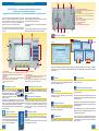
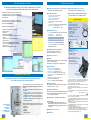
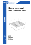
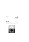
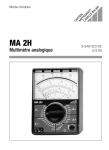
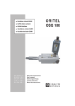
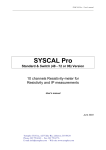
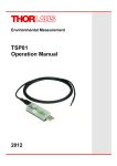
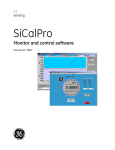
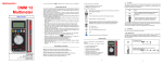
Specify in the following sequence: ORITEL RO 600-4, function,
language, option and mains lead
User-friendly, quick and accurate
■ Models from 1 to 2700 MHz
ORITEL RO 600-4
X
XX
XXXX
ORITEL
RO 600
• Functions
SWR + Insertion loss (IL) . . . . . . . . 1
SWR + IL + Fault location. . . . . . . 2
• Language for messages
and user's manual
French . . . . . . . . . . . . . . . .
English . . . . . . . . . . . . . . . . . .
German . . . . . . . . . . . . . . . . .
Italian . . . . . . . . . . . . . . . . . . .
Spanish . . . . . . . . . . . . . . . . .
.
.
.
.
.
.
.
.
.
.
.
.
.
.
.
.
.
.
.
.
.
.
.
.
.
.
.
.
.
.
.
.
.
.
.
.
.
.
.
.
FR
GB
AL
IT
ES
Accessories
• Programming option
Without . . . . . . . . . . . . . . . . . . . . . . . . . . XXXX
IEEE interface . . . . . . . . . . . . . . . . . . . . . . . . . IEEE
• Mains lead
French, German
English . . . . . . .
Italian . . . . . . . .
Swiss . . . . . . . .
and Spanish . . . . . . . . . . . . . . . . . . 01
. . . . . . . . . . . . . . . . . . . . . . . . . . . . . . . 02
. . . . . . . . . . . . . . . . . . . . . . . . . . . . . . . 03
. . . . . . . . . . . . . . . . . . . . . . . . . . . . . . . 04
■ NB: The "French" model below is codified
ORITEL RO 600-4-2-FR-XXXX-01
. . . . . . . . .P01.2701.13
■ Other models
Reduced frequency range versions of the RO 600 can be
produced upon request (0.8 to 1.5 GHz - 0.8 to 2.7 GHz 1.5 to 2.7 GHz)
State of delivery
All models come with user's manual, network mains lead and battery
charger.
Carrying case
with numerous pockets
for storing accessories.
•
•
•
•
Storing case . . . . . . . . . . . . . . . . . . . . . . . . .P01.2980.59
Carrying case . . . . . . . . . . . . . . . . . . . . . . .P01.2980.45
IEEE 488 programming interface . . . . . . . . . . .P01.2703.04
LOG 600, PC application software . . . . . . . . .P01.2703.05
in 5 languages (FR, GB, AL, IT and ES) supplied with
RS 232 link and installation manual
• AMP 601, 30 dB amplifier . . . . . . . . . . . . . . .P01.2703.06
1 MHz to 1 GHz with BNC plug/socket cable
• AMP 602, 30 dB amplifier . . . . . . . . . . . . . . . .P01.2703.07
0.8 to 2 GHz with BNC plug/socket cable
• LOD 600, 3-load kit . . . . . . . . . . . . . . . . . . . .P01.2703.08
N plug (SWR = 1.2 - 1.5 and 2.0)
• ATT 600, 4-attenuator kit . . . . . . . . . . . . . . . .P01.2703.12
N plug/N socket (3 - 6 - 10 and 20 dB)
• Calibrating reference load . . . . . . . . . . . . . . . .P01.2703.27
SWR = 3.0 L (16.67 Ω)
• Calibrating reference load . . . . . . . . . . . . . . . .P01.2703.26
SWR = 3.0 H (150 Ω)
• CC 600, accessory case . . . . . . . . . . . . . . . . .P01.2703.03
containing:
➤ 1 overload protector
➤ 1 short circuit/open circuit
➤ 1 adapted load/50 Ω
➤ 1 N socket/N socket adapter
➤ 1 Nm/Nm adapter
➤ 1 flexible coaxial cable: Nm/Nm,
50 cm
➤ 1 N tee
NB: The CC 600
case components
are available separately.
Ask for details.
Your distributor:
TEST & MEASUREMENT DIVISION
FRANCE
190, rue Championnet
75876 PARIS Cedex 18
Tel: +33 1 44 85 44 85
Fax: +33 1 46 27 73 89
e-mail : [email protected]
www.chauvin-arnoux.com
Microwave
Scalar
Tester
XX
UNITED KINGDOM
Waldeck House - Waldeck Road
MAINDENHEAD SL6 8BR
Tel: 01628 788 888
Fax: 01628 628 099
e-mail : [email protected]
www.chauvin-arnoux.co.uk
906 211 021 - Ed. 1 - 07/2001 - Characteristics subject to modifications according to technological developments. AVANA 33 2 38 77 88 88
To order
Metallic case
for the tester
and the ensemble
of its accessories.
Order references
Designed to be equally at home in the field
as in the laboratory.
■ Measures SWR, gain and insertion loss, in sweep and fixed
frequency (CW) modes. Accurately locates faults along coaxial cables.
■ Does not require a highly skilled operator.
■ Autonomous, easily set up, interacts in the user's language...
1 MHz to 2.7 GHz
User-friendly, quick and accurate
❼
❽
❾
The ORITEL RO 600 is an instrument specifically designed for both on-site
operations testing and laboratory measurements.
Equipped with its IEEE 488 interface, it can constitute a programmable scalar analysis bench.
A few of its numerous strong points: ergonomically accessible
functions, no specific skill requirements for use, quick set-up
with its scroll menus, interacts in user's language, accuracy
of measurement, saves measurement configurations and
calibrations, stores up to 40 measurement files...
For the field, the RO 600 is designed to inspect and analyse
the quality of broadcasting installations from 1 MHz to
2.7 GHz.
7 - Power supply output for amplifiers
BNC plug connector delivers 15 Vdc to supply the AMP 601 and
AMP 602 amplifiers.
8 - Recorder output
BNC socket connector delivers a voltage proportional to the
measured quantity. 1 V full scale on a load impedance superior
to 1 kΩ.
9 - Power supply input
Connector for the battery charger (115 to 230 Vac) or direct
supply of 12 to 24 Vdc (cigar lighter)
10 - RS 232 interface connector
11 - Earth terminal
12 - IEEE 488 interface connector (optional)
It measures SWR, gain and insertion loss.
It locates faults along coaxial connecting cables (cut, crushed,
poorly installed and oxidised connectors).
The same measurements can be applied in the laboratory for
all quadripoles.
Its LOG 600 software provides numerous ways to analyse and
exploit measurement curves on the PC with Windows(tm).
❿
❻
Interacts in 5 languages
Deutsch
Francais
English
❺
❶
❹
Italiano
❷
❸
1 - Control keyboard
Corresponds to 2 distinct keyboards, a numeric keyboard, accessible during
configuration phases, and a generic function keyboard, accessible at all times
2 - ON/OFF Button
3 - Soft keys
These 4 keys give access to the secondary menus and are displayed at the bottom
of the screen. They depend on the RO 600's configuration.
4 - Insertion Loss measurement input
N socket
Autonomy for use on-site
5 - SWR measurement output
N socket
6 - Liquid Crystal Display
A 128 x 240 pixels matrix for displaying curves, numerical values, menus and
messages in plain text. With backlighting and adjustable contrast.
6a - Status Indicators
When the mode is programmed using the IEEE 488 bus, the status of the bus is
indicated by pointers that light up opposite the status symbols.
CONTROLE BATTERIE
- Tension de batterie
: 12.1 V
- Courant de décharge : 810 mA
- Autonomie
:
On site, the RO 600 is immediately operational. In fact, less
than a minute is required after it is turned on for it to stabilise and
enter into its accuracy class.
RETOUR
In summer as in winter
On site, ambient temperatures do not
hinder the RO 600's performance. Measurements
are made with the same accuracy during
summer (and in warm-climate countries: up to
+ 55°C) as during winter (and at high altitudes:
down to - 10 °C) as in the laboratory.
2
Messages are displayed in the language chosen when ordering. When the RO 600 is switched on, it specifies its configuration:
frequency range, presence of fault location and Interface IEEE 488 options, recommended date for next calibration and changing
the back-up cell...
Calibration
No wasting time recalibrating for each operation configuration,
the RO 600 retains and uses its calibration files in all cases,
even after the power has been cut.
Operational in less than a minute
Equipped with its internal battery, the
RO 600 has 3 to 5 hours of operating
autonomy depending upon the operating
configuration. Before leaving for the site,
simply press the "battery" key to see the
status of its charge.
The RO 600 can be supplied by all 115 to 230 Vac (48 Hz to
420 Hz) mains while using its battery charger. As soon as the
charger is connected to the mains, the battery automatically
starts charging, even when the RO 600 is not switched on.
The supply can also be provided by a vehicle, directly by a 12 or
24 Vdc cigar lighter.
Measurement file management
All information concerning saved files (up to 40 measure
curves) are accessible in their table form with this control
key. With notes: the name of the file, the operator and the
site, as well as the measurement configuration, the date
and time of the file's recording,... along with other management information.
Frequency domain
Key for determining the work frequency or the frequency
domain to be explored.
Measuring in disturbed environments
Special functions
This key is for different configuration settings and updates,
notably screen contrast adjustment, video reverse display,
date and time settings...
Measurement selection
The measure to be made is simply selected among the choices
offered by the soft keys: SWR, reflection coefficient in voltage or
dB, insertion loss, or fault location.
Storing and recalling
With the "STO" key, up to 40 measurement curves
(200 "frequency/measurement" or "distance/measurement" point couples) as well as 3 operating configurations
can be saved.
The "RCL" key serves to display any recorded curve and recall
any configurations on the screen.
Español
Operating mode
The operating mode is selected among the three choices offered by
the soft keys: sweep, single sweep, or fixed frequency mode (CW).
The RO 600 can withstand parasitic RF reinsertion up to + 19 dBm
with no risk of damage.
If the level of parasitic RF risks being higher than this, the level
of protection can be increased to + 25 dBm using the "overload
protection" accessory.
The RO600 is constructed with protection against disturbances
provoked by RF interference which is carried back to the input
during measurement.
However, in the event where an excessive level of interference
disturbs the measure, the "Supplementary protection" can be
accessed with the "Antenna" key.
In this way the effects of the RF interference caught by the
antenna are attenuated by at least another 30 dB, regardless
of their frequency and nature: CW, modulated in amplitude,
phase or frequency.
3
SWR measurement
Fault location
Impedance mismatching, which is rated by Standing Wave Ratio (SWR) measurements,
is the tester's primary feature for ensuring a valid energy transfer
between generator and its load circuit.
Carrying out the acceptance test for a new RF communications installation
and its maintenance also means checking continuity
in the connecting coaxial cables between the transmitter/receiver and the antenna.
The RO 600 performs this measurement in about ten seconds
with excellent accuracy.
With the RO 600, there is nothing more simple than making installation adaptation checks and adjusting components up to 2.7 GHz.
This impedance adaptation can express itself in three forms:
Voltage Reflection Coefficient (ρV), Reflection Coefficient in dB (ρdB)
or Return Loss, and Standing Wave Ratio (SWR).
SWR
measurement
of a passband
filter being
adjusted.
Configurations are made very rapidly, using the soft key corresponding
to the desired measurement, such as SWR, reflection coefficient
in dB or in voltage. No need to recalibrate.
In two seconds, the adaptation frequency response is displayed,
making it possible to make adjustments in the components'
dynamics.
Return Loss
measurement
(ρdB) of the same
filter, displayed on
the number 2
measurement
scale from
0 to 20 dB.
The interpretation of the measurement, made in sweep mode, is
facilitated by two, permanently available functions: rapidly changed
measurement scales and the marker's positioning which gives the
exact value of the measure and frequency corresponding to its position on the curve.
Insertion Loss measurement
When we want to rate a piece of telecommunications equipment, it is worthwhile making sure
that the connecting cable between the transmitter (or the receiver) is in perfect condition,
and that it will not prevent the transmission of energy.
To this end, the cable should not generate a too considerable "Insertion Loss."
The RO 600 directly measures the insertion loss of any
quadripole in sweep mode in its frequency range. The
measurement takes two seconds and provides a resolution
of 0.1 dB. The measured curve can be immediately stored.
The rapidly changed measurement scale and the marker's
movement (giving the frequency and insertion loss) makes
it easy to analyse and interpret the results.
Measurement and
display of the variation
of the Insertion
Loss of the component
in its frequency range
with a resolution
of 0.1 dB.
Generally installed outside, coaxial connecting cables are subject
to attacks from external agents. They can undergo abnormal
stress and become defective. This type of situation can end
with disturbance, perhaps even an interruption in transmission.
The principle faults include:
• Oxidation of the contact element of a connector
• Unscrewed or short-circuited connectors
• Crushing of a cable
These connecting cables are very often long, because the
antennae are generally placed on roofs or at the top of a pole
several dozen meters high.
It is therefore advisable to have a tester capable of accurately
locating a possible transmission fault prior to any maintenance
servicing.
To do this, the RO 600 measures the frequency response of
the reflection coefficient of the cable being tested, a frequency
response characteristic of the nature and position of one or
many faults along the cable path.
An algorithm, based on the "Inverse Fourier Transform"
calculation, makes it possible to accurately locate this impedance discontinuity.
Up to 900 meters
In 10 seconds, the sought-after fault is located with an
accuracy of 0.5 % for distances included between a few
centimetres and 900 meters (according to the nature of the
cable being used).
The measurement configuration is particularly simple because
it does not require recalibration. Just choose the soft key
corresponding to the desired measurement: fault location in
SWR, ρV or ρdB (Return Loss).
The measurement can be carried out on either side of the
cable's regular operating frequency; its value is entered by
using the "FREQ" frequency control key. At any time, the
operator can choose among 7 possibilities on a distance
scale.
At any time, it is possible to locate the most pronounced fault
or faults (up to 10) with high accuracy with the "Marker" function.
Step 1:
Automatic configuration by direct access
to the reference of the cable being tested,
within the list of recorded references,
or by manual configuration by entering
the different electrical characteristics of the cable.
ANT 1
ANT 2
S.W.R. output measurement
■ Antennae decoupling measurement
When positioning a new antenna on a developed site, it is
essential to determine the decoupling value between the antenna
being installed and the already existing antennae.
In just a few seconds, the RO 600 delivers this measurement,
in sweep mode, for the entire frequency range being examined.
Step 2:
AMP600 Power
supply output
Amplifier input
006OR
AMP600
Power supply input +15V
DC
I.L. input measurement
Variation
measurement
for antennae
decoupling
in a frequency
band.
Personalization of the measurement
range and the analysis frequency range
according to the installation's characteristics.
S.W.R. output measurement
Step 3:
Ampli.
Variation
measurement
of an amplifier's
gain in its
frequency range.
4
Attenuator
■ Gain amplifier measurement
I.L. input measurement
With the Insertion Loss function (a RO 600 standard feature),
it only takes a few seconds to check the response curve and
measure the gain of any kind of amplifier, without recalibrating.
Measurement and analysis.
This cable has a pronounced fault at 2.53 m followed
by a lesser one at 2.75 m, corresponding to the
connections going through a partition.
Measurement accuracy is ± 3 cm.
5
LOG 600 application software
For analysing and exploiting the results on a PC (WindowsTM starting with the 3.11 version),
in one of the five languages available: French, English, German, Italian, Spanish.
With the optional LOG 600 software, stored measure files
in the RO 600, as well as, the automatic representations of
corresponding measurement curves can be automatically
recovered by a PC.
Principal characteristics
■ Operating mode: Automatic sweep or single sweep (200
measurement counts) and fixed frequency (CW)
■ Measurement dynamics
Amongst its many functions, it offers:
•
•
•
•
•
•
•
•
•
•
•
expression of measurements in 5 languages,
importation of files,
saving of files,
exportation of files to EXCEL,
automatic representation of measurement curves and
remarks,
display of one or more curves simultaneously,
printing of curves,
marker movement with display of its co-ordinates,
cursor use with XY labelling of corresponding values,
min./max. search,
representation and scale unit conversions.
■ Measurement accuracy
• I.L.: ±0.5 dB between 0 and 20 dB (± 0.25 dB typical)
•ρV
with standard (2)
calibration reference
±
±
±
±
0.01
0.025
0.05
0.15
from
from
from
from
0.025
0.071
0.21
0.51
to 0.07
to 0.20
to 0.50
to 0.80
•ρV
with SWR 3.0 (2)
calibration references
±
±
±
±
±
0.01
0.025
0.05
0.10
0.15
Rated voltage: 30 V max - Overvoltage category I
■ Electromagnetic compatibility and susceptibility:
• SWR: 1 to 1.8 - 1 to 3 and 1 to 21
• Voltage reflection coefficient
ρV: 0 to 0.4 - 0 to 0.8 and 0 to 1
• Reflection coefficient in dB
ρdB: 0 to 20 - 0 to 40 and 10 to 50 dB
• Insertion loss
I.L.: 0 to 10 - 0 to 20 and 0 to 30 dB (offset function)
• Fault location: 5 cm to 856 m for ε = 1.3 (1)
3.8 cm to 966 m for ε = 2,3
The software operates in a WINDOWSTM environment and
offers the user this environment's exploitation possibilities as
well as those of LABWINDOWSTM.
■ Electrical safety (IEC 1010, ed. 08/93):
from
from
from
from
from
0.025
0.071
0.21
0.41
0.61
to
to
to
to
to
0.07
0.20
0.40
0.60
0.80
• Fault location: resolution = 5.10-3 x max distance
of measurement range (3)
■ Field mode (antenna measurements)
HF overloads permitted ≤ +25 dBm/50 Ω
Attenuation of HF interference ≥ 30 dB (5)
(4)
■ Connectors: N socket / 50 Ω
■ Displays
Alphanumeric display of response curves and results on backlit
LCD 240 x 128 count matrix.
Messages in French, English, German, Italian, Spanish.
According to NF EN 50 081-1 and NF EN 50 082-1
Accessories
■ Amplifiers
- AMP 601: 2 MHz to 1 GHz
- AMP 602: 800 MHz to 2 GHz
Delivered with BNC socket/BNC socket
mains lead.
Connectors: N plug/N socket
• Gain: 30dB ± 2 dB
• P 1dB: ≥ + 16 dBm
• IP3: ≥ + 33 dBm
• NF: ≤ 5 dB
• Power supply: 15 V dc - 120 mA
■ Calibration reference loads
Reference load
Resistance
SWR
SWR Accuracy
Maximum Power
SWR 3H
SWR 3L
150 Ω
16.7 Ω
3.0
3.0
± 0.08 max (± 0.04 typical)
average 1W
■ LOD 600 3-load Kit ❶
• SWR values: 1.2 - 1.5 and 2.0
• Accuracy: ± 5 %
• Max. Power: average 1W
• Connector: N plug
■ ATT 600 4-attenuator Kit ❷
• Attenuation values: 3-6-10 and 20 dB
• Accuracy: ± 0.40 dB
• Maximum Power: average 1W
• Connectors: N plug/N socket
❷
■ Internal generator
Programming with IEEE 488 bus
All of the RO 600's functions which are configured with the control keyboard and soft keys
are accessible in programmed mode using the IEEE 488 bus.
•
•
•
•
•
Frequency range: 1 to 2700 MHz
Frequency increment: minimum 10 kHz
Frequency accuracy: better than ±5.10-6 (6)
Frequency stability: better than ±1.10-6 over one year
Frequency resumption: accuracy better than ±1.10-5 in
one minute (7)
• Harmonic and non-harmonic spectral purity:
better than 35 dB (40 dB typical)
• Output level: 0 dBm ±1 dB at middle frequency
■ Recording of results
The major advantage of this programmed functioning mode
lies in the total reproducibility of configurations and measurement
readings.
This two-way communication enables the RO 600 to operate
in two modes:
• Receiver (or listener) - This mode is used during the
programming phase when the bus controller sends the
instrument the commands necessary for its configuration.
• Transmitter (or talker) - In reply to requests, the RO 600
transmits to the controller the results of the calculations and
measurements performed.
With its IEEE 488
interface,
the RO 600 can
constitute a
programmable scalar
analysis bench.
6
During communications with the bus controller, the status of the
RO 600 is given on the display by pointers that correspond to
its four states:
• RMT (remote)
• TLK (talk)
• LSN (listen)
• SRQ (service request)
40 storage registers of 200 couples of "Frequency - SWR or ρ"
or "Distance - SWR or ρ" counts (8)
■ Communication interfaces
File transfers by RS 232 interface, IEEE 488 interface (optional)
and by recorder output proportionate to the measurement: (0 to
1 V/1 kΩ) on BNC socket connector
■ Programming: as per IEEE 488 standard (optional)
■ Power supply
• By internal battery (Ni-MH), typical autonomy: 3.5 hrs (9)
• By external charger: 115 to 230 V (140 VA, 48 to 63 Hz)
• By externally fed direct power supply: between 12 and 24 V
(50 W max)
■ Dimensions: 250 x 125 x 275 mm
The loads ❶
and the attenuators ❷
fit nicely in the CC 600
accessory case.
❶
(1) The maximum distances of the 7 measurement scales depend upon the
dielectric constant value of the cable being tested. The fault's amplitude is
represented in SWR, ρV or ρdB, with the 7 corresponding scales.
(2) Tolerances specified on ρV, after calibration.
When using the "PRO600" protection accessory ("Overload" function in Field
mode), add +0.1 to the previous tolerances.
When using the "Parasite" function of Field mode, add +0.05 to the tolerances
specified on ρV.
The corresponding tolerances for
following relations:
ρdB
and for SWR will be reduced by the
ρdB
= 20 log
ρV
SWR =
1 + ρV
1 - ρV
(3) The accuracy of fault location depends on the knowledge of the actual
dielectric constant of the cable being tested.
(4) On the SWR measurement Input, with the protection accessory in use
("Overload" function of Field mode activated), value is restored + 19 dBm if the
"PRO600" is not used.
(5) Typical value for an injected HF disturbance level of 0 dBm (with Field mode
"Parasites" function activated)
(6) On the fixed frequency (CW), the marker frequency, the start, stop, and middle
frequencies of the domain swept
(7) When power is switched on after being cut off
(8) Also includes measurement configuration information, plus the names of the
file, the operator and the site, as well as the date and time of the file.
(9) Autonomy varies between 3 and 5 hrs depending upon the configuration of
the instrument, charge time approximately 3.5 hrs.
■ Weight: 4.8 kg
7