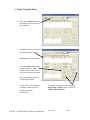
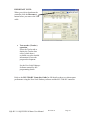
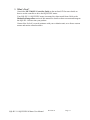
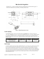
1
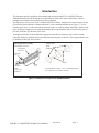
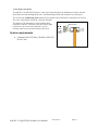
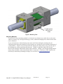
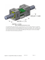
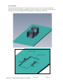
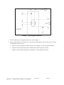
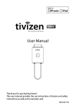
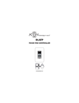
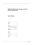
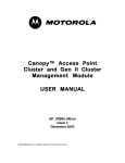
SQL-RV-1.8 SQUIGGLE® Motor
User Manual
Revision A
January, 2010
January 2014: SQUIGGLE motors are no longer sold separately;
they are available only as part of an integrated motion module.
New Scale Technologies, Inc
121 Victor Heights Parkway
Victor NY, 14564
Phone: (585)-924-4450
Fax: (585)-924-4468
Sales: [email protected]
Service: [email protected]
Web: www.newscaletech.com
© 2009 New Scale Technologies, Inc. All rights reserved. No part of this publication may be
reproduced, stored in a retrieval system or transmitted, in any form or by any means, electronic
or mechanical, including photocopying, recording, or otherwise, without the prior written
permission of New Scale Technologies, Inc
SQUIGGLE is a registered trademark of New Scale Technologies, Inc.
Windows, Vista and ActiveX are registered trademarks of Microsoft Corporation.
SQL-RV-1.8 SQUIGGLE® Motor User Manual
Revision A
Table of Contents
Introduction......................................................................................................................... 1
System requirements....................................................................................................... 2
Safety .................................................................................................................................. 3
Safety Precautions........................................................................................................... 3
Handling Precautions ...................................................................................................... 3
Environmental Requirements.......................................................................................... 3
Warnings and Cautions ................................................................................................... 3
Set up the SQUIGGLE® Motor ......................................................................................... 4
1. Connect the motor(s) to the controller. ................................................................... 4
Connect the controller to your PC or handset................................................................. 5
2. Connect the power .................................................................................................. 5
3. Install the New Scale Pathway Software ................................................................ 6
4. Begin Using the Motor............................................................................................ 9
5. What’s Next? ........................................................................................................ 11
Mechanical Integration ..................................................................................................... 12
Load coupling ............................................................................................................... 12
Limit stops .................................................................................................................... 12
Vibration Effects........................................................................................................... 13
Mounting....................................................................................................................... 13
Mounting Methods.................................................................................................... 14
Snap-In Method .................................................................................................... 16
Adhesive Method .................................................................................................. 18
Clamp Method – Not Using Mount Tabs ............................................................. 20
Clamp Method – Using Mount Tabs .................................................................... 20
Reference Design Example for SQL-RV-1.8 ........................................................... 23
Connecting the Motor ................................................................................................... 27
SQL Series SQUIGGLE Motor Electrical Characteristics ........................................... 28
Drive signals ................................................................................................................. 28
General Operational Guidelines and Best Practices ......................................................... 30
Troubleshooting ................................................................................................................ 31
Troubleshooting chart ................................................................................................... 31
Maintenance...................................................................................................................... 33
Re-threading the Screw................................................................................................. 33
Cleaning the Screw ....................................................................................................... 33
To Clean the Screw:.................................................................................................. 33
Index ................................................................................................................................. 34
SQL-RV-1.8 SQUIGGLE® Motor User Manual
Revision A
Page: i
This page intentionally left blank.
SQL-RV-1.8 SQUIGGLE® Motor User Manual
Revision A
Page: ii
Introduction
This document provides guidelines for mounting and driving the SQL-RV-1.8 SQUIGGLE motor.
Additional instructions for driving the motor and using the New Scale motor control demo software
package can be found in the controller and software manuals.
The SQL Series motor is New Scale’s smallest SQUIGGLE motor. An SQL Series motor consists of four
piezoelectric plates bonded to a threaded metal tube, with a matching threaded screw (figure 1). A twochannel square wave is used to bend the piezoelectric plates to create an orbital “hula hoop” motion of the
tube, causing the mating screw to rotate and translate. Reversing the phase shift reverses the direction of
the orbit, and hence the direction of the screw.
The highest efficiency of the mechanical coupling between the tube and the screw is achieved at the
ultrasonic frequency matching the first bending resonant frequency of the tube. This is approximately 100
to 200 KHz for the SQL Series motors.
SQUIGGLE Motor Assembly
(un-mounted, un-wired)
Orbital “hula
hoop”
Vibration
Piezoelectric
Plates (4)
Threaded
Nut
Nodes
Threaded
Screw
(rotates and
translates)
Motor
Core
1st Bending Mode of Motor “Core” in 2 Orthogonal Planes
(Two nodes have zero lateral movement.)
Figure 1. Anatomy of an SQL Series SQUIGGLE Motor
SQL-RV-1.8 SQUIGGLE® Motor User Manual
Revision A
Page: 1
A note about your motor
The SQL-RV-1.8 SQUIGGLE motor is a tiny linear motor that delivers millimeters of stroke with submicrometer precision and high push force. It withstands high shock and consumes very little power.
You will use the rounded tip of the screw to press against a flat, hard surface on the load to be moved.
The screw will push the load in the “forward” direction.
The motion of the load must be in line with the shaft
centerline as shown. The motor works best with a slight
return force (5g) to move the load in the “reverse”
direction when you reverse the motion of the screw.
Rounded tip of
drive screw
Motion
System requirements
•
Loading
Force
Computer with a CD drive; Windows 2000, XP
Pro or Vista.
SQL-RV-1.8 SQUIGGLE® Motor User Manual
Revision A
Page: 2
Safety
Note the following precautions and requirements.
Safety Precautions
•
•
•
Be mindful of exposed connections.
Use only 2.3V-5.5V input voltage.
Do not connect or disconnect components while power is on.
Handling Precautions
•
•
•
•
•
Do not hold or transport the motor by the flex circuit. Avoid over handling, crimping or
damaging the flex circuit. Do not subject the flex circuit to bend radii smaller than 0.04”
[1.0mm].
Do not remove the motor from its housing.
Handle all components with care. Treat this product as you would a laptop computer or an
optical microscope.
Do not lubricate the motor. Do not expose the motor to lubricating materials.
Certain components are susceptible to damage from electrostatic discharge. Observe all
ESD procedures to avoid component damage.
Environmental Requirements
•
•
•
Do not use in wet or damp conditions or in an explosive atmosphere.
Do not operate in a corona vacuum pressure range (100 to 10-3 Torr).
Keep working surfaces clean, dry and static-free.
Warnings and Cautions
These terms may appear in this manual:
WARNING identifies conditions or practices that could result in damage, injury or loss of life.
CAUTION identifies conditions or practices that could result in damage to this product or other
property.
DANGER indicates an injury hazard immediately accessible as you read the marking.
SQL-RV-1.8 SQUIGGLE® Motor User Manual
Revision A
Page: 3
Set up the SQUIGGLE® Motor
Use the following instructions to set up and begin using your SQUIGGLE® motor and MC-3300-RV
controller.
1. Connect the motor(s) to the controller.
You can connect the motor directly to the controller. The MC-3300-RV controller drives
one or two motors.
Do not plug motor into MC-3300 (high voltage) controller as the components are not
compatible and damage may occur to the motor.
Flip up the brown tab on the controller daughter board at J6 (and J5, if you have two
motors).
With the copper connection side down,
gently slide the motor flex circuit into
place. Close the tab.
Caution: Make sure there is some
slack in the flex circuit to avoid
damaging solder connections.
Flip brown tab to open
Controller
Pre-mounted
motor
J6 (motor 1)
J5 (motor 2)
SQL-RV-1.8 SQUIGGLE® Motor User Manual
Revision A
Page: 4
Connect the controller to your PC or handset
Connect the Mini USB connector to the controller at J3
on the mother board. Then connect the USB cable to your
computer.
Mini USB connector
J3
2. Connect the power
Connect the power input cable to the controller at J1 on
the mother board.
Caution: The power input cable has a keyed connector
that fits only one way. It should never be forced. The red
wire should connect to pin 1.
J1 is a keyed
connector observe
polarity. Do
not force.
Power
input
cable
J1
Plug the power input cable into the power supply.
Be sure to connect the power input cable to the controller
before you apply power.
Plug the power supply to a power source. An LED on the
controller lights when power is applied.
Power supply
Power input cable
SQL-RV-1.8 SQUIGGLE® Motor User Manual
Revision A
Page: 5
3. Install the New Scale Pathway Software
Next, install the New Scale Pathway software to control the motor from your PC.
(You may skip this step if you will be using ONLY the optional manual handset.)
a. Locate the software
installation disk.
b. Place the disk in the
computer drive.
The NST installer window will
appear automatically.
Do not connect controller yet!
c. Identify the motor/encoder
controller provided with
your order.
d. Select the controller from
the list in the “Choose Your
Controller” menu.
e. If an encoder is included
in the order, check the
“Include Support for
Tracker Sensor” check box.
f. Click “Install” to install the
software.
If a Microsoft warning appears,
click OK to continue.
SQL-RV-1.8 SQUIGGLE® Motor User Manual
Revision A
Page: 6
You may also view the New Scale
manuals or save them to disk at this
time.
When the installation is complete,
remove the disk.
g. Connect the USB cable
from the computer to the
controller as shown.
The first time the USB
connection is made, the system
will install a USB driver and
motor driver on the local hard
drive
Instruct the system to find the
drivers locally.
SQL-RV-1.8 SQUIGGLE® Motor User Manual
Revision A
Page: 7
Do the following to run the Pathway
demo software and select the
communication port.
h. Double Click on the New
Scale Pathways icon on
desktop to start
application.
i. Click on “Setup Connection”
to open connection dialog.
j. Select the desired USB port
(that you wish to connect
the controller to).
Highlight the desired USB
port and click “Select” to
select the port.
k. Click the “Test Selected
USB/COM Ports…” button
to test the selected port.
Click “Close” when the
connection is complete.
SQL-RV-1.8 SQUIGGLE® Motor User Manual
Revision A
Page: 8
4. Begin Using the Motor
•
Click the Connect button in
the main menu to connect to
the controller.
•
Available motors are listed in
the motor control window.
Highlight the desired motor.
•
Click the Fwd and Rev Run
Control and Jog Control
buttons to move the motor as
you observe motor operation.
Encoder equipped systems
will display position.
See the New Scale Pathways
Software manual for more
detailed operating
instructions.
SQL-RV-1.8 SQUIGGLE® Motor User Manual
To change the motor speed: change the
Motor Step Control values or use the
%Max Speed slide bar
Revision A
Page: 9
IMPORTANT NOTE:
When you wish to shut down the
controller click the Disconnect
button before you remove the USB
cable.
•
Test encoder (Tracker)
operation.
Select the Tracker tab to
display the Tracker data
screen, which shows
available axes plus detailed
information for encoder
program development.
See the New Scale Pathways
Software manual for full
programming details.
Refer to the MC-3300-RV Controller Guide for full details on how to evaluate motor
performance using the New Scale Pathway software and the MC-3300-RV controller.
SQL-RV-1.8 SQUIGGLE® Motor User Manual
Revision A
Page: 10
5. What’s Next?
Consult the MC-3300-RV Controller Guide on the enclosed CD for more details on
how to use the controller to drive the SQUIGGLE motor..
Your SQL-RV-1.8 SQUIGGLE motor is mounted in a sheet metal frame. Refer to the
Mechanical Integration section of this manual for details on how to mount and integrate
the SQL-RV-1.8 motor into your product.
Contact New Scale if you need assistance with your evaluation unit, or to discuss custom
motors and motion control modules.
SQL-RV-1.8 SQUIGGLE® Motor User Manual
Revision A
Page: 11
Mechanical Integration
The SQL-RV-1.8 motor mechanical structure and dimensions are shown below (figure 2).
Electrical connections are provided by a flexible printed circuit.
Figure 2. Mount Dimensions (in mm)
Load coupling
The SQUIGGLE motor, for its size, provides relatively large linear forces. The motor must not be
subjected to rotational friction forces. One end of the SQUIGGLE motor’s screw has a polished radiused
tip to minimize rotational friction. For optimal performance, this radiused screw tip should contact a
hardened, polished, low-friction surface. Suggested materials include graphite-loaded Vespel SP21, and
Delrin ® Acetal.
Recommended Materials
Contact Area
Thickness
Surface Finish
DuPont Vespel ® SP21
or Delrin ® Acetal
Diameter > .08in
> .025in
1 microinch
Limit stops
As with any threaded system, driving the SQUIGGLE motor screw linearly into a physical stop increases
the risk of jamming the threaded components and possibly causing permanent damage to the motor.
Linear “hard” stops should be avoided. “Soft” or electrical limits such as optical sensors or magnetic
Hall-effect sensors are recommended. As an alternative to soft/electrical limits, New Scale Technologies,
Inc. has developed and patented a mechanical limit method utilizing a low-torque motion-limiting feature
that can be integrated into your system. For more details, please contact our Custom Product Division
(585-924-4450, ext. 153).
SQL-RV-1.8 SQUIGGLE® Motor User Manual
Revision A
Page: 12
Vibration Effects
It is important to note that induced vibrations (other than from the motor itself) have the potential to move
the screw when the motor is not in operation. This can lead to improper positioning, allowing the screw
to move past a forward or reverse limit. Due to this phenomenon, it is critical that a preload be applied to
ensure continued operability of the mechanism and engagement of the screw in the nut in the case that
vibration induced movement has occurred.
Mounting
Attaching a fixture to the sheet metal-mounted SQUIGGLE motor introduces the potential for damping
and structural non-symmetry in the motor assembly, resulting in sub-optimal orbital motion. This can
limit the maximum motor speed and push force. Consider your system and motor requirements when
considering the mounting techniques that follow.
Screw Play – Keep in mind that there is ‘screw play’ in the fit between the screw and the nut, meaning
the screw is not rigidly fixed in the nut when the motor is not running.
•
Axial play: +/- .0205mm
•
Radial play: +/- 1.2 degrees
USE MOUNTING TABS
SQL-RV-1.8 SQUIGGLE® Motor User Manual
Revision A
Page: 13
CLAMP ONTO
MOUNTING
TABS
Figure 3. Mounting Tabs
Mounting Methods
The goal in all of these mounting methods is to limit and even eliminate any outside forces on the motor
while it is mounted. By securing the housing by its tabs, additional clamping forces induced on the motor
can be eliminated.
To prevent interference with the housing or the motor itself when utilizing the mounting tabs, the
following graphic depicts the dimensions of the clearance area, and therefore the maximum dimensions of
a mating feature. “Depth” is the maximum allowable distance the mating feature can go past the edge of
the mounting tab, without interfering with the motor. “Width” is simply the width of the tab, and
therefore the maximum width that the mating feature should be. “Height” is the maximum height that the
mating feature should be, without interfering with the “cross beam”. CAD files in .STEP format for the
motor may be obtained by submitting an inquiry on our web site at www.newscaletech.com.
SQL-RV-1.8 SQUIGGLE® Motor User Manual
Revision A
Page: 14
Figure 4. Mounting (all dimensions in mm)
It is possible that the end of the motor can protrude past the end of the housing. Therefore it is important
to take that into consideration when integrating the motor into your own structure. Allow a clearance of at
least 0.25mm between the end of the housing and any part of the system that the motor is being integrated
into. If the end of the motor comes in contact with another part of the system, it could severely dampen
the vibration of the motor and reduce performance.
SQL-RV-1.8 SQUIGGLE® Motor User Manual
Revision A
Page: 15
Snap-In Method
The Snap-In Method consists of an “integration structure” with a recess to accept the bottom datum
(Datum A) of the motor housing, constraining it in the X and Y axes. Two “snap tabs” would secure the
housing in the recess by clamping onto the mounting tabs, constraining it in the Z axis.
Figure 5. Snap-In Method
SQL-RV-1.8 SQUIGGLE® Motor User Manual
Revision A
Page: 16
Drawing 1 – Snap Integration Structure
1. Refer to Drawing 1 for integration features, as well as Figure 4.
2. Insert one Mount Tab into “Snap Tab 1”, then insert the other Mount Tab into “Snap Tab 2” so that
the following criteria are met:
a. Datum A of the housing should mate with the recess (Datum A) of the integration structure
b. Datum B of the housing should mate with Datum B of the integration structure.
c. Datum C of the housing should mate with Datum C of the integration structure
SQL-RV-1.8 SQUIGGLE® Motor User Manual
Revision A
Page: 17
Adhesive Method
The Adhesive Method consists of the same type of recess as in the Snap-In Method, but without the snap
tabs. Instead, an epoxy or adhesive tape applied to Datum A of the housing would be used to secure the
motor housing in the recess.
Figure 6. Adhesive Method
SQL-RV-1.8 SQUIGGLE® Motor User Manual
Revision A
Page: 18
Drawing 2 – Adhesive Integration Structure
1. Refer to Drawing 2 for integration features, as well as Figure 4
2. Apply a thin layer of adhesive or epoxy to Datum A of the housing.
3. Place the motor assembly into the recess of the integration structure so that the following criteria are
met:
a. Datum A of the housing should mate with the recess (Datum A) of the integration structure.
b. Datum B of the housing should mate with Datum B of the integration structure.
c. Datum C of the housing should mate with Datum C of the integration structure.
*Using the same type of recess, a 100g load could be applied (evenly distributed) to the top of the housing in
order to secure it to Datum A. Applying a larger load could introduce extra dampening to the motor, which
would degrade motor performance.
SQL-RV-1.8 SQUIGGLE® Motor User Manual
Revision A
Page: 19
Clamp Method – Not Using Mount Tabs
This first Clamp Method does not utilize the mount tabs. It consists of the same concept as the Adhesive
Method, but with a separate part (preferably a thin sheet metal part) that is screwed into the integration
structure in two different places and clamps onto the top of the housing. Again, make sure this clamping
force does not exceed 100g.
Figure 7. Clamp Method – Not Using Mount Tabs
Clamp Method – Using Mount Tabs
The Clamp Method consists, again, of the same recess as before, but with a separate part that is screwed
into the integration structure and clamps onto one of the mounting tabs, while the other mounting tab
slips into a “pocket”.
SQL-RV-1.8 SQUIGGLE® Motor User Manual
Revision A
Page: 20
Figure 8. Clamp Method – Using Mount Tabs
SQL-RV-1.8 SQUIGGLE® Motor User Manual
Revision A
Page: 21
Drawing 3 – Clamp Integration Structure
1. Refer to Drawing 3 for integration features, as well as Figure 4.
2. Insert one Mount Tab into the “Pocket” feature so that the following criteria are met:
a. Datum A of the housing should mate with the recess (Datum A) of the integration structure
b. Datum B of the housing should mate with Datum B of the integration structure
c. Datum C of the housing should mate with Datum C of the integration structure
3. Screw the “Clamp” into the integration structure so that it secures the motor housing in place by
clamping down on one of the Mount Tabs.
SQL-RV-1.8 SQUIGGLE® Motor User Manual
Revision A
Page: 22
Reference Design Example for SQL-RV-1.8
The following outlines a reference design for the mechanical integration of a SQL-RV-1.8-6-12 motor.
CAD files in .STEP format for the reference design assembly may be obtained by submitting an inquiry
on our web site at www.newscaletech.com.
Spring Loaded
Sliding Stage
O-ring
This reference design consists of two spring-loaded, rail-mounted sliding stages which are moved by the
SQL-RV-1-8 motor. These stages prevent the screw from falling out by holding it in the motor’s counter
bore, even when the screw is in an over-travel position.
A rubber o-ring is also included on the secondary stage’s rail to restrict the spring force to one direction.
The following figures depict the reference design configuration in five conditions:
1. Centered position
2. Forward normal travel position
3. Forward over travel limit
4. Reverse normal travel position
5. Reverse over travel limit
SQL-RV-1.8 SQUIGGLE® Motor User Manual
Revision A
Page: 23
Centered Position
•
•
•
•
Screw is centered in the motor.
Screw threads are fully engaged.
Secondary Stage (Left) is stopped by the rubber o-ring.
Primary Stage (Right) is in contact with the screw.
Forward Normal Travel Position
•
•
•
•
Screw is at the forward limit of normal travel.
Screw threads are still fully engaged in motor.
Primary stage is touching the front tip of the screw.
Secondary stage is stopped by the o-ring.
SQL-RV-1.8 SQUIGGLE® Motor User Manual
Revision A
Page: 24
Forward Over Travel Position
•
•
•
•
Screw is at the maximum forward over-travel.
Screw threads are disengaged, the screw rotates but no longer moves in the forward
direction.
The screw is captured by the motor counter bore and the spring force of the primary stage,
ensuring that screw does not fall out.
Secondary stage is stopped by the o-ring.
Reverse Normal Travel Position
•
•
•
•
Screw is at the reverse limit of normal travel.
Screw threads are still fully engaged in motor.
Primary stage has lost contact with the front tip of the screw and is stopped by the motor
housing.
Secondary stage is touching the back tip of the screw.
SQL-RV-1.8 SQUIGGLE® Motor User Manual
Revision A
Page: 25
Reverse Over Travel Limit
•
•
•
•
Screw is at maximum reverse over-travel.
The threads are disengaged; the screw rotates but no longer moves in the reverse direction.
Primary stage has lost contact with the front tip of the screw and is stopped by the motor
housing.
The screw is captured between the motor counter bore and the spring force of the secondary
stage ensuring that the screw can not fall out.
SQL-RV-1.8 SQUIGGLE® Motor User Manual
Revision A
Page: 26
Electrical integration
A direct linear drive circuit offers the most compact design and is capable of producing the voltage
required by the SQL-RV-1.8 motor.
New Scale offers the MC-3300-RV direct linear drive motor controller for integration into OEM
instruments or for use as a reference design. Each MC-3300-RVcontroller operates up to two SQUIGGLE
motors. The controller accepts position feedback from commercially available analog or digital position
sensors, allowing complete closed-loop control.
The MC-3300-RV controller includes motor control software for Windows XP and Vista. An ActiveX
control is included, and may be integrated into other applications written in languages such as C++ or
Visual Basic. The controllers can also accept ASCII commands or input from an optional manual handset.
See the controller documentation for the low-level ASCII control codes that an embedded system or
microcontroller would send to a motor control chip.
Connecting the Motor
The SQUIGGLE motor’s FPC connects to a common FFC/FPC 6-position, .5mm-pitch SMD connector
from Hirose (part # FH12-6S-0.5SH; see www.hirose.com).
Figure 9. FPC Pin-out
SQL-RV-1.8 SQUIGGLE® Motor User Manual
Revision A
Page: 27
To connect the SQUIGGLE motor to an electrical driver board or adapter cable, lift the rotational fliplock actuator with a thumb or index finger (figure 9). Fully insert the connector end of the FPC, stiffener
side up/exposed conductive trace side down, until it nests into the FPC connector. Close the rotational
flip-lock actuator. The same steps are used to remove the FPC from the mating connector.
1. Lift the
rotational flip-
2. Insert the FPC
3. Close the rotational
flip-lock actuator
Figure 9. Connecting the flex printed circuit (FPC)
SQL Series SQUIGGLE Motor Electrical Characteristics
Motor model
SQL-RV-1.8
Input power
< 340mW at 2.8V; MC-3300-RV driver
Input voltage
5.5V max; as low as 2.3V for light loads
Optimal drive frequency
168 – 174kHz
Capacitance per phase
~48nF
Input power is specified assuming the motor is driven by the MC-3300-RV Controller. New Scale has
developed OEM drivers that draw lower power, and works with OEMs to build motor and driver
combinations that are right for each application.
Drive signals
SQL-RV-1.8 SQUIGGLE® Motor User Manual
Revision A
Page: 28
Input parameters for ICs capable of generating square waves typically include period and duty
cycle. Other parameters may include phase and amplitude. Parameter values for the SQLRV-1.8 motor are below. Please refer to the NSD-2101 Datasheet and MC-3300-RV Datasheet
for more motor control details.
Parameter
Description
Value for SQL-RV-1.8
Period
The time between the start of each cycle. The
inverse of frequency. For a SQUIGGLE motor,
this must match or be near the period of the
mechanical resonance of the tube.
Inverse of ~171 KHz; or ~5.85 μsec
Duty cycle
The time that the drive signal is high within
each cycle
No more than 50% of the period
Phase
The separation in time between the start of a
cycle in each drive signal
25% of the period
Amplitude
The maximum voltage achieved at each cycle
Up to 5.5V max. For light loads, this
can be as low as 2.3V.
SQL-RV-1.8 SQUIGGLE® Motor User Manual
Revision A
Page: 29
General Operational Guidelines and Best Practices
Important! Do not use the FPC as a means to transport the SQUIGGLE motor. Handle the motor
carefully by the ends of the screw or the sides of the motor body. Subjecting the FPC to any force may
result in a permanently damaged, non-functioning motor.
Important! The exposed screw shaft should not be subjected to any lateral forces. The only driving
contact should be the radiused tip of the screw. Side-loading the screw may impede motor performance
and/or permanently damage the motor.
Important! Contact with the FPC should be minimized. Repeated bending of the FPC may result in
permanently damaged, non-functioning motor. The FPC should not be subjected to bend radii smaller
than .04” [1.0mm].
Important! Forward and rear of the motor’s linear travel, hard mechanical stops should be avoided.
Driving the screw into a mechanical obstruction may jam the threads of the motor, preventing further
operation and/or causing permanent damage.
Important! The screw threads of your SQUIGGLE motor are a precision fit. Take care to avoid
contaminating the threads with debris or lubricants. Introduction of such matter into the mating threads
may degrade motor performance and contribute to premature motor failure. If debris is caught in the
motor during evaluation testing or in a laboratory application, the screw may be removed and cleaned
with an isopropyl alcohol solution. Carefully re-insert the screw, making sure that the radiused end is
used to drive the load.
Important! The SQUIGGLE motor operates best under a slight return force of 5 grams applied axially
against the radiused tip of the screw. It is important to note that the total axial load, including this return
force, is not to exceed 20 grams for the SQL-RV-1.8 motor.
SQL-RV-1.8 SQUIGGLE® Motor User Manual
Revision A
Page: 30
Troubleshooting
Troubleshooting chart
If the following remedies do not work, call New Scale Technologies for service.
Symptom
Causes
Remedies
Controller LED does
not light.
Power supply not connected
or improperly connected.
Connect the power input cable to the
controller at J1 on the mother board.
Caution: The power input cable has a
keyed connector that fits only one way.
It should never be forced. The red
wire should connect to pin 1.
Controller set on metallic
surface.
Properly insulate the bottom of the
controller.
Motor incorrectly installed.
Connect the power input cable to the
controller at J1 on the mother board.
Caution: The power input cable has a
keyed connector that fits only one way.
It should never be forced. The red
wire should connect to pin 1.
Wrong axis (motor) selected
in New Scale Pathway
software.
Select the correct axis (motor) on the
Motor Control tab of the New Scale
Pathway software.
Too much load on motor.
Check the Test Data sheet shipped
with the motor and motor specifications
for maximum motor load.
Motor shorted.
Move metallic surfaces away from the
motor.
Crimped or broken flex
circuit.
Check for damage to the flex circuit.
Using incorrect motor
controller.
Make sure you are using a MC-3300RV controller and not a MC-3300 (high
voltage) controller.
Too much progressive load
on motor.
Reduce progressive load.
Dirty screw.
Clean screw. See “Cleaning the
Screw” on page 33.
Controller timeout error.
Recycle power and restart New Scale
Pathway software.
Using incorrect motor
controller.
Make sure you are using a MC-3300RV controller and not a MC-3300 (high
voltage) controller.
Motor mount not securely
fastened.
Verify that motor mount is securely
fastened to your test bench or fixture.
Too much load on motor.
Reduce motor load.
Motor does not move.
Motor moved initially
but stopped moving.
Motor does not push
to spec.
SQL-RV-1.8 SQUIGGLE® Motor User Manual
Revision A
Page: 31
Symptom
Causes
Remedies
Using incorrect motor
controller.
Make sure you are using a MC-3300RV controller and not a MC-3300 (high
voltage) controller.
Low speed setting in New
Scale Pathway software.
Raise the speed setting in the New
Scale Pathway software.
Dirty screw.
Clean screw. See “Cleaning the
Screw” on page 33.
Too much load on motor.
Reduce the motor load.
Check mounting fixture.
Using incorrect motor
controller.
Make sure you are using a MC-3300RV controller and not a MC-3300 (high
voltage) controller.
No available USBbased controllers
listed after using
Setup Connection
button.
The USB driver may not be
installed or after the
controller was connected to
the PC and powered,
Windows may have asked to
reinstalled the driver and this
request was ignored by the
operator
Reinsert the New Scale Pathway
software CD and select the MC-3300RV controller to see if the USB driver
must be installed. If it is shown, click
Install to force an installation.
If it’s not shown in the list box below, it
is already on the system.
If already installed, disconnect and
reconnect the USB cable and see if
Windows prompts to reinstall the
driver, if so, let it find the driver locally.
Screw runs completely
out of motor shaft.
Motor runs for too far in one
direction.
Re-thread the screw. See
“Re-Threading the Screw” on page 33.
Slow motor speed.
SQL-RV-1.8 SQUIGGLE® Motor User Manual
Revision A
Page: 32
Maintenance
Re-threading the Screw
If you run the motor for too long in one direction, it can run completely out of the motor shaft.
If this occurs, carefully re-thread the screw clockwise, with either end facing into the motor shaft.
Cleaning the Screw
The SQUIGGLE motor normally performs well in an open setting without any contamination. This is true
whether or not the motor is integrated in a module or housing.
Occasionally, dirt particles may accumulate on the screw, which can reduce motor performance. If this
happens, clean the screw.
To Clean the Screw:
1. Clean the screw with an isopropyl alcohol solution.
WARNING: Flammable liquid and vapor. Harmful if swallowed or inhaled. Causes
irritation to eyes and respiratory tract. Affects central nervous system. May be harmful if
absorbed through skin. May cause irritation to skin.
For more information, refer to the MSDS for Isopropyl Alcohol.
2. Blow dry the screw using clean, compressed air.
SQL-RV-1.8 SQUIGGLE® Motor User Manual
Revision A
Page: 33
Index
Adhesive Method, 18
Anatomy of an SQL-RV SQUIGGLE Motor, 1
Begin Using the Motor, 9
Clamp Method – Not Using Mount Tabs, 20
Clamp Method – Using Mount Tabs, 20
Cleaning the Screw, 33
Connect the controller to your PC or handset, 5
Connect the motor(s) to the controller, 4
Connect the power, 5
Connecting the flex printed circuit (FPC), 28
Connecting the Motor, 27
Drive signals, 28
Electrical Characteristics, 28
Electrical integration, 27
Environmental Requirements, 3
General Operational Guidelines and Best
Practices, 30
Handling Precautions, 3
Install the New Scale Software, 6
Introduction, 1
Limit stops, 12
Load coupling, 12
Maintenance, 33
SQL-RV-1.8 SQUIGGLE® Motor User Manual
Mechanical Integration, 12
Mount Dimensions (in mm), 12
Mounting, 13
Mounting Methods, 14
Mounting Tabs, 14
Note about your motor, 2
Preload, 13
Reference Design Example for SQL-RV-1.8, 23
Re-threading the Screw, 33
Safety, 3
Safety Precautions, 3
Screw
Cleaning, 33
Re-threading, 33
Set up the SQUIGGLE® Motor, 4
Snap-In Method, 16
System requirements, 2
Troubleshooting, 31
Troubleshooting chart, 31
Vibration Effects, 13
Warnings and Cautions, 3
What’s Next?, 11
Revision A
Page: 34
Notes:
New Scale Technologies, Inc.
121 Victor Heights Parkway
Victor NY, 14564
Phone: (585) 924-4450
Fax: (585) 924-4468
Sales: [email protected]
Service: [email protected]
Web: www.newscaletech.com