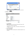
1
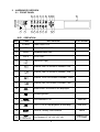
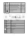
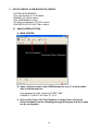
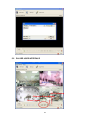
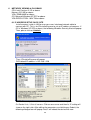
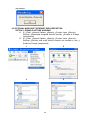
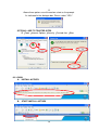
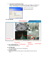
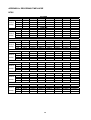
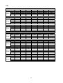
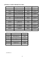
USER MANUAL
4 CHANNELS
DIGITAL VIDEO RECORDER
026YREB-1.01
INSTRUCTION MANUAL
To obtain the best performance and ensure device function correctly, please read this instruction manual
carefully and completely.
TABLE OF CONTENTS
2
WARNINGS, CAUTIONS & COPYRIGH.....................................................................................
3
TABLE OF CONTENTS...............................................................................................................
4
1
INTRODUCTION.................................................................................................................
4
1.1 FEATURE..................................................................................................................
4
1.2 SPECIFICATION.......................................................................................................
5
2
HARDWARE OVERVIEW....................................................................................................
5
2.1 FRONT PANEL..........................................................................................................
6
2.2 BACK PANEL............................................................................................................
7
2.3 EXTERNAL ALARM..................................................................................................
9
2.4 IR REMOTE CONTROL............................................................................................
10
2.5 RS485 CONTROLLER..............................................................................................
11
2.6 PTZ (PAN, TILT, AND ZOOM) CAMERA & JOYSTICK CONTROLLER...................
13
2.7 VGA OUTPUT...........................................................................................................
13
2.8 NETWORK................................................................................................................
14
3
SYSTEM SETUP.................................................................................................................
15
3.1 MENU SETUP LIST...................................................................................................
15
3.2 LIVE VIEWING..........................................................................................................
16
3.3 SYSTEM SETUP.......................................................................................................
17
3.4 CAMERA SETUP......................................................................................................
17
3.5 MOTION SETUP.......................................................................................................
18
3.6 RECORD SETUP......................................................................................................
20
3.7 ALARM SETUP.........................................................................................................
21
3.8 EVENT LIST..............................................................................................................
22
3.9 HDD MANAGEMENT................................................................................................
23
3.10 NETWORK SETUP...................................................................................................
24
3.11 FIRMWARE UPDATE................................................................................................
24
3.12 CD / DVD RW BACKUP.............................................................................................
24
3.13 LOAD DEFAULT........................................................................................................
25
4
DVR PLAYBACK & USB BACKUP......................................................................................
25
4.1 PLAY TIME SEARCH................................................................................................
25
4.2 EVENT LIST SEARCH..............................................................................................
26
4.3 USB BACKUP............................................................................................................
5
DVR PLAYBACK & USB BACKUP...................................................................................... 27
5.1 MAIN SCREEN SETUP.............................................................................................
27
5.2 PLAYER USER INTERFACE....................................................................................
28
6
NETWORK VIEWING & PLAYBACK...................................................................................
29
6.1IP ADDRESS SETUP ON PC SITE...........................................................................
29
6.2 OPTIONAL MICROSOFT INTERNET EXPORER SETUP........................................
30
6.3 LOGIN........................................................................................................................
31
6.4 LIVE VIEWING..........................................................................................................
32
6.5 CONFIGURE............................................................................................................. 34
41
APPENDIX A: RECORDING TIME LAPSE.................................................................................
43
APPENDIX B: HDD / USB COMPATIBLE LIST...........................................................................
1
INTRODUCTION
1.1 FEATURE
Easy operation; setting can be easily modified on screen.
Multi-speed recording selection on normal or alarm recording mode up to 120/
100 (NTSC/ PAL)) pictures per second.
Multi-language.
Support Manual/ Alarm/ Schedule recording mode.
Built-In RS-485 port to control PTZ cameras or Joystick controllers for DVR.
Support CDRW, DVDRW, USB, and Network Backup.
Support 2 x HDD (500GB) to record for up to 6 months with real-time record.
1.2 SPECIFICATION
System Type
Resolution – Live
NTSC
720×480
PAL
720×576
Video Input
BNC × 4
Video Looping
BNC × 4
Video Output
BNC × 2
Audio Input
RCA × 1
Audio Output
RCA × 1
Storage Media
Max. 2 x IDE HDD (one Removable)
Compression Format
MPEG-4
Recording Rate
720 × 240 up to 30 PPS
360 × 240 up to 120 PPS
Recording Mode
Manual/ Alarm/ Schedule
Playback Speed
Fast Forward ×2 ×8 ×16 ×32 ×64
Fast Backward ×32
Slow Forward 1/2 1/4
Field by Field Playback
Title
6 Characters for each Camera
OSD & Setup
Title/ Time/ Date/ Setup Menu
Alarm Input
× 4 N.O./ N.C. Programmable
Relay Output
× 1 N.O./ N.C. Programmable
RS-485 Port
Yes
PTZ Control
Yes
Network Compression Format
MPEG-4
IR Remote Control
Yes
Backup
USB, CD R/W, DVD R/W, & Network
VGA Output
Optional
Password
For System and HDD Format
Key Lock
Yes
Power Input
DC 12V / 5A
Dimensions W×H×D (mm)
Weight
432 (W) × 55 (H) × 321 (D)
5.0 Kg
3
720 × 288 up to 25 PPS
360 × 288 up to 100 PPS
2
HARDWARE OVERVIEW
2.1 FRONT PANEL
5
6
7
8
9
10
11
12
13
14
15
16
20 17 21
22
1
2
3
4
23
24
DVR OPERATION
NO.
ITEM
18 19
DVR Function
1
POWER
2
REC
Recording status LED.
3
PLAY
Playback status LED.
4
H.D.D
H.D.D. LED.
5
6
7
8
9
10
11
12
13
14
15
Copy
1
2
3
4
Quad
REC
Rew Search
STOP
Pause
F.Fwd Search
PTZ Function
Power status LED.
Confirm or Copy.
Channel One Full Screen & Number: One.
Channel Two Full Screen & Number: Two.
Channel Three Full Screen & Number: Three.
Channel Four Full Screen & Number: Four.
Quad screen: All cameras are displayed.
Recording button.
Fast Backward × 32.
Zoom out
Press STOP to stop playback or recording.
Auto scan
Pause & Field by Field Forward.
Fast Forward ×2, ×8, ×16, ×32, ×64.
4
Home
Enter or Exit
PTZ mode
16
PLAY
PLAY button & Get into Quick Time Search.
17
Move upward or increase the number.
18
Move downward or decrease the number.
19
MENU
Press MENU to enter or exit MENU.
Zoom in
Up
Down
PTZ Setup
20
Move leftward or decrease the number.
Left
21
Move rightward or increase the number.
Right
22
HDD
23
HDD, CD R/W, and DVD R/W.
USB connector.
24
O
IR Sensor for remote control.
2.2 BACK PANEL
NO.
ITEM
FUNCTION
1
LED
Reserve.
2
Ethernet
Reserve.
3
CAMERA OUT
Camera 1-4 video output with BNC connector.
4
CAMERA IN
Camera 1-4 video input with BNC connector.
5
MONITOR OUT
Composite Output can connect with the monitor directly and
support two BNC outputs.
6
S VIDEO OUT
Y/C Output. (Optional)
7
Audio in / out
Audio Input/ Output.
8
Ethernet
RJ-45 Network Interface.
9
VGA OUT (D-SUB)
Connect to CRT or LCD monitor. (Optional)
RS-485
4-Pins. Connect to Joystick controller or PTZ control.
ALARM IN
4-Pins. Alarm input.
Relay
Relay output.
11
Power/ Power
Switch
Reserve.
12
Power
DC 12V /5A.
13
Spot OUT
Spot output
10
5
2.3 EXTERNAL ALARM
There are three types of alarms that the system can be configured, such as
Motion Detection Alarm, External Alarm, and Video Loss Alarm.
Motion Detection Alarm and External Alarm
When Motion Detection or External Alarm was triggered, there are 5 possible
actions will be taken.
a. Recording speed changed from normal to alarm recording.
b. If Alarm Display Mode of Alarm Setup is ON, when the alarm is triggered,
the corresponding full screen alarm channel will be displayed
automatically; however, if the alarm is triggered and the setup is done
within five seconds, the corresponding full screen alarm channel won’t be
displayed.
c. It’s optional to activate Relay.
d. Motion Detection and External Alarm both will be recorded in the event list.
In Motion Detection Record of Alarm Setup, the user can set up ON or
OFF to record the motion event or not.
e. When Motion Detection was triggered, the color of camera title will be
transformed into yellow. In addition, when External Alarm was triggered,
“ALARM” text will be displayed on the screen.
Video Loss Alarm
The default setting of Video Loss Alarm is enabled. The recorded time of Video
Loss Alarm depends on the time of buzzer. The event will be added into the
event list automatically and Video Loss text will be displayed on the
corresponding channel.
6
Terminal Connectors
T+
T-
RS-485 sends +
RS-485 sends -
R-
RS-485 receives -
R+
RS-485 receives +
ALARM1-4
Camera alarm input.
GND
GND.
N.C
Relay N.C.
COM
Relay COM
N.O
Relay N.O.
EXAMPLE 1Connect Alarm In One with PIR (Passive Infrared).
EXAMPLE 2Connect with Alarm Siren at Relay N.O.
7
2.4 IR REMOTE CONTROL
ITEM
AUTO
Reserve.
SEL
Reserve.
REC
Press REC to start recording and press twice to stop.
1-4
Select channel 1-4 with full screen.
Fast backward.
Picture by picture backward.
Picture by picture forward.
Fast Forward.
Play video forward.
MODE
Switch channel format.
Move upward or increase the number.
Move rightward or increase the number.
Move downward or decrease the number.
Move leftward or decrease the number.
Enter selected items.
MENU
Enter or Exit Main Menu.
STOP
Stop the playback.
8
2.5 RS-485 CONTROLLER
RS-485
PIN
R+
RT+
T-
DEFINE
RXDA
RXDB
TXDZ
TXDY
Data Format
Data: 1 Byte / Parity: None / Start bit: 1 / Baud: 9600
Totally 3 bytes as follows:
1. Byte=0x10
Broadcasting DVR
Byte=0x80+ID Number
Joystick Control DVR (ID
number:1~32)
2. Byte=Reference to the table as follows. Commands of each button.
: Command for confirm checksum.
3. Byte= the 1st Byte+ the 2nd Byte
4-ch DVR
Command
4-ch DVR
Command
CH1
0x11
PLAY
0x52
CH2
0x12
UP
0x31
CH3
0x13
DOWN
0x32
CH4
0x14
MENU
0x20
QUAD
0x15
LEFT
0x33
RFAST
0x3A
RIGHT
0x34
STOP
0x51
SELECT
0x35
PAUSE
0x3D
ENTER
0x35
FFAST
0x3E
9
2.6 PTZ (PAN, TILT AND ZOOM) CAMERA & JOYSTICK CONTROLLER
The following diagram is for DVR connect PTZ camera with joystick controllers.
Make sure CAMERA ID, BAUD RATE (default at 9600 bps) and RS-485 +/-. If
the user wants to connect DVR with joystick controllers, please make sure each
DVR ID Number is unique.
Up to 16CH
Up to 16CH
R+ R- T+ T-
R+ R- T+ T-
Dome Cam 4
CH 4
ID 4
Dome Cam 4
CH 4
ID 4
Dome Cam 3
CH 3
ID 3
Dome Cam 2
CH 2
ID 2
Dome Cam 1
CH 1
ID 1
A B A B
0 1 0 1
Dome Cam 3
CH 3
ID 3
Dome Cam 2
CH 2
ID 2
D0+ D0- D1+ D1-
Up to 128 ID
R+ R- T+ T-
Dome Cam 3
ID 3
Up to 128 ID
D0+ D0- D1+ D1-
A B A B
D+ D- D+ D-
Dome Cam 2
ID 2
D+ D- D+ D-
A B A B
DVR 1
ID 1
DVR 2
ID 2
Dome Cam 1
ID 1
Up to 32 ID
DATA+
DATA10
PTZ SETUP & FRONT PLANE CONTROL
EXAMPLE:
A PTZ camera at channel 3 with PELCO-D, 9600bps.
1. Press the channel button 3 with full screen mode.
2. Press
and “PTZ” will appear at right upper corner.
REC 2005/10/10 MON 12:00:00 50% 120P
PTZ
3. Press the MENU button to get into setup mode.
Press
or
to switch item & by
BAUD RATE.
or
to change SPEED/ PROTOCOL &
REC 2005/10/10 MON 12:00:00 50% 120P
PTZ
PTZ SETUP
O
UP-DOWN SPEED: OOOOO
O
LEFT-RIGHT SPEED: OOOOO
O
AUTO SCAN SPEED: OOOOO
O
PROTOCOL TYPE: PELCO-D
O
BAUD RATE:
9600
4. Press MENU twice to get back to PTZ control mode.
5. Control PTZ camera by pressing the following buttons.
NO.
PTZ
NO.
18
Down
15
19
Left
13
20
Up
12
21
Right
11
Rew
Search
PTZ setup
14
F.Fwd
Search
16
ITEM
MENU
6. Press SEL to quit PTZ control mode.
11
ITEM
PLAY
PAUSE
Stop
PTZ
Zoom in
Home
Auto Scan
Zoom out
Enter or exit
PTZ mode
2.7 VGA OUTPUT
VGA Output is optional. VGA output can connect with CRT or LCD monitor by
D-SUB connector and the user can switch different resolutions and frequencies
as follows.
Resolution
Frequency
VGA
640×480
56Hz
SVGA
800×600
60Hz
XGA
1024×768
70Hz
SXGA
1280×1024
75Hz
2.8 NETWORK
When the DVR is turned on, it will detect the network connection automatically.
If without network connection, the network function will be disabled. Thus,
please make sure the network connection before turning on the DVR.
12
3
SYSTEM SETUP
3.1 MENU SETUP LIST
SETUP MENU
SYSTEM SET
CAMERA SET
MOTION SET
RECORD SET
ALARM SET
EVENT LIST
HDD MANAGEMENT
NETWORK SET
FIRMWARE UPDATE
CD/DVD RW BACKUP
VGA SET
LOAD DEFAULT
EXIT
1. SYSTEM SETUP
[<]
[<]
[<]
[<]
[<]
[<]
[<]
[<]
[<]
[<]
6. EVENT LIST
DATA FORMAT
DATE
TIME
AUTO SWITCH DWELL
DATE AND TIME OSD
SYSTEM TYPE
KEYBOARD LOCK
ID NUMBER
LANGUAGE SELECT
PASSWORD MODE
EXIT
2. CAMERA SETUP
MASTER PAGE : 001
NO YY/MM/DD HH:MM:SS CH
01
05/10/10
00:01:00
-02 05/10/10
00:02:00
-03 05/10/10
00:03:00
01
04 05/10/10
00:04:00
02
05
05/10/10
00:05:00
03
06
05/10/10
00:06:00
-07 05/10/10
00:07:00
-08 05/10/10
00:08:00
01
09 05/10/10
00:09:00
02
Y-M-D
2007/03/29
10:10:10
03
ON
NTSC
OFF
01
CH/ENG
DISABLE
CAMERA
DISPLAY
BRIGHTNESS
CONTRAST
HUE
COLOR
CAMERA TITLE
EXIT
TYPE
POWER
RECORD
V.LOSE
ALARM
MOTION
POWER
RECORD
V.LOSE
ALARM
CAM01
ON
50
50
50
50
01
3. MOTION SETUP
7. HDD MANAGEMENT
OVERWRITE MODE
CAPACITY WARNING
HDD FORMAT SETUP
EXIT
OFF
20%
[<]
DISK CAPACITY
MASTER
SLAVE
RATIO
41%
NONE
LEFT
80GB
NONE
CAMERA
MOTION DETECTION
BUZZER
SENSITIVITY
AREA SETUP
EXIT
4. RECORD SETUP
8. NETWORK SETUP
TITLE
IP MODE
IP ADDR
SUB NET
GATEWAY
DNS1
DNS2
HTTP PORT
EXIT
SCHEDULE RECORD
NORMAL RECORD PPS
ALARM RECORD PPS
RECORD MODE
ALARM RECORD DWELL
RECORD QUALITY
AUDIO RECORD
EXIT
DVR
MAUNAL
192.168.001.220
255.255.255.000
192.168.001.254
168.095.001.001
168.095.192.001
00080
9. FIRMWARE UPDATE
FIRMWARE UPDATE START
OFF
30P
30P
MUX
10SEC
HIGH
ON
5. ALARM SETUP
[<]
BUZZER
BUZZER ALARM DWELL
VIDEO LOSS ALARM
AUDIBLE ALARM
EXT. ALARM MODE
ALARM DISPLAY MODE
MOTION EVENT
RELAY
EXT. ALARM RELAY
VIDEO LOSS RELAY
MOTION RELAY
EXIT
10. CD/DVD RW BACKUP
START TIME SETUP
START:
END :
BACKUP SIZE:
CLOSE DISK:
ERASE DISK:
BACKUP START:
EXIT
CAM01
ON
OFF
080
[<]
[<]
2006/11/20 00:00:00
2006/11/20 02:00:00
0000MB
YES
NO
[<]
13
05SEC
ON
ON
N.C
OFF
OFF
ON
ON
ON
3.2 LIVE VIEWING
A. Quick playback search
With live viewing mode, press
PLAY to get into Quick Time Search and do
playback or search by time or event.
B. PTZ control
a. Press the button of PTZ camera no. and the picture will be displayed with full
screen mode.
b. Press
to get into PTZ mode and PTZ text with yellow color will be
displayed at upper right corner.
c. Press MENU to set up Protocol & Baud rate between DVR and PTZ
cameras.
d. Press the direction key to control PTZ cameras.
e. Press
to exit PTZ mode.
C. Channel selection
During split channel format,
1,
2,
3 &
4, the user can use the
channel button to switch different channels with full screen mode.
14
3.3 SYSTEM SETUP
1. SYSTEM SETUP
DATA FORMAT
DATE
TIME
AUTO SWITCH DWELL
DATE AND TIME OSD
SYSTEM TYPE
KEYBOARD LOCK
ID NUMBER
LANGUAGE SELECT
PASSWORD MODE
EXIT
Y-M-D
2007/03/29
10:10:10
03
ON
NTSC
OFF
01
CH/ENG
DISABLE
Press
Press
or
or
to select items.
to change values.
A. DATE FORMAT
Press
or
to switch Y-M-D, M-D-Y, or D-M-Y mode.
B. DATE
Press
or
to select items and
or
to change values.
C. TIME
Press
or
to select items and
or
to change values.
D. AUTO SWITCH DWELL
Press
or
to change values.
Press
key first and then press
key , system would into full screen
auto switch mode.
E. DATE AND TIME OSD
Press
or
to select items and
or
to change values.
F. SYSTEM TYPE
NTSC or PAL.
G. KEYBOARD LOCK
Press
or
to switch ON/ OFF.
OFFUNLOCK.
ON LOCK.
After KEYBOARD LOCK mode setup, please set up PASSWORD
Without password, un-authorized users could access into SYSTEM SETUP
and make changes of settings easily.
H. ID NUMBER
Press
or
to change values.
When connecting with the joystick controller, ID NUMBER is required to make
difference of each DVR.
I. LANGUAGE SELECT
Press
or
to change OSD language.
J. PASSWORD MODE
Press
or
to select items and
Default password: 1111
.
15
or
to change values.
3.4 CAMER SETUP
2. CAMERA SETUP
CAMERA
DISPLAY
BRIGHTNESS
CONTRAST
HUE
COLOR
CAMERA TITLE
EXIT
Press
Press
CAM01
ON
50
50
50
50
01
or
or
to select items.
to change values.
A. CAMERA
Press
or
to switch channels.
B. DISPLAY
Press
or
to change value for the corresponding camera would be
displayed on the screen or not.
C. BRIGHTNESS
Press
or
to change brightness level.
D. CONTRAST
Press
or
to change contrast level.
E. HUE
Press
or
to change HUE level.
F. COLOR
Press
or
to change color level.
G. CAMERA TITLE
Press
or
to select items and
or
to change character.
3.5 MOTION SETUP
3. MOTION SETUP
CAMERA
MOTION DETECTION
BUZZER
SENSITIVITY
AREA SETUP
EXIT
CAM01
ON
OFF
080
[<]
Press
Press
or
or
to select items.
to change values.
A. CAMERA
Press
or
to switch channels.
B. MOTION DETECTION
Press
or
to change value for motion detect function.
C. BUZZER
Press
or
to change value for buzzer while motion detected.
D. SENSITIVITY
Press
or
to change sensitivity value from 001 (minimum) to 100
(maximum).
E. AREA SETUP
Press ENTER to enter motion area setting.
1. Press direction keys to select which block is needed.
2. Press
to add a line of motion detection area.
3. Press
to remove a line of motion detection area.
4. Press MENU to quit motion detection area setup.
16
3.6 RECORD SETUP
4. RECORD SETUP
SCHEDULE RECORD
NORMAL RECORD PPS
ALARM RECORD PPS
RECORD MODE
ALARM RECORD DWELL
RECORD QUALITY
AUDIO RECORD
EXIT
Press
Press
OFF
30P
30P
MUX
10SEC
HIGH
ON
or
or
to select items.
to change values.
A. SCHEDULE RECORD
Press
or
to change value for schedule record function.
A1. SCHEDULE RECORD SETUP
When SCHEUDLE RECORE is ON, press ENTER to enter SCHEDULE
RECORD SETUP.
RECORD SETUP
WEEKDAY: MON-FRI
START-STOP
TYPE
01-00
[X]
00-01
[0]
PPS
20P
20P
ALM PPS
60P
60P
WEEKEND: SAT-SUN
START-STOP
TYPE
ALL-TIME
[X]
PPS
20P
ALM PPS
60P
Press
Press
or
or
to select items.
to change values.
EXIT
A1.1
WEEKDAY & WEEKEND
SCHEDULE RECORD SETUP is divided into two parts, weekday and weekend.
They can be set up with different FPS.
EXAMPLE 1:
If Weekday is from Monday to Friday, Weekend will be Saturday and Sunday.
EXAMPLE 2:
If Weekday is from Wednesday to Friday, Weekend will be from Saturday to
Tuesday.
EXAMPLE 3:
If Weekday is from Monday to Wednesday, Weekend will be from Thursday to
Sunday.
EX1
EX2
EX3
MON
TUE
WEB
THU
FRI
SAT
SUN
WEEKDAY
WEEKEND
WEEKEND
WEEKDAY
WEEKEND
WEEKDAY
WEEKEND
A1.2
START-STOP
24 Hours can be set with ALL TIME or SEPERATED HOUR modes.
17
ALL TIME
Apply the same recording mode and PPS whole day.
SEPERATED HOUR
Like WEEKDAY & WEEKEND setting, the user can set 24 hours with 2 parts
and set 2 different PPS.
EXAMPLE 1
Business Hour: 8am - 16pm.
Off Time: 16pm - 8am.
EXAMPLE 2
Business Hour: 10am-20pm.
Off Time: 22pm - 10am.
2
EX1
EX2
A1.3
TYPE
Press
A
O
X
A1.4
PPS
Press
4
OFF
or
8
OFF
6
10
12
14
16
18
BUSINESS HOURS
BUSINESS HOURS
20
22
24
OFF
OFF
to change recording mode.
Alarm recording only
Full time recording
No recording
or
A1.5
ALM PPS
Press
or
to change normal recording picture per second.
to change alarm recording picture per second.
NTSC 30 / 15 / 10 / 5 / 3 / 2 / 1 PPS
PAL 25 / 12 / 10 / 5 / 3 / 2 / 1 PPS
B. NORMAL RECORD PPS
Press
or
to switch PPS in normal recording.
C. ALARM RECORD PPS
Press
or
to switch PPS in alarm recording.
D. RECORD MODE
Press
or
to switch MUX and QUAD record mode.
With MUX, the resolution is 720 x 240 (NTSC)/ 720 x 288 (PAL).
With QUAD, the resolution is 360 x 240 (NTSC)/ 360 x 288 (PAL).
E. ALARM RECORD DWELL
Press
or
to set dwell time of alarm recording.
F. RECORD QUALITY
Press
or
to switch LOW/ MEDIUM/ HIGH/ BEST.
G. AUDIO RECORD
Press
or
to switch AUDIO RECORD ON or OFF.
NOTE: In Duplex mode, the audio is disabled on playback.
18
3.7 ALARM SETUP
5. ALARM SETUP
BUZZER
BUZZER ALARM DWELL
VIDEO LOSS ALARM
AUDIBLE ALARM
EXT. ALARM MODE
ALARM DISPLAY MODE
MOTION EVENT
RELAY
EXT. ALARM RELAY
VIDEO LOSS RELAY
MOTION RELAY
EXIT
05SEC
ON
ON
N.C
OFF
OFF
Press
Press
or
or
to select items.
to change values.
ON
ON
ON
BUZZER
A. BUZZER/ ALARM DWELL
Press
or
to set dwell time of BUZZER/ ALARM.
B. VIDEO LOSS ALARM
Press
or
to switch VIDEO LOSS ALARM ON or OFF.
C. AUDIBLE ALARM
Press
or
to switch AUDIBLE ALARM ON or OFF.
D. EXT. ALARM MODE
Press
or
to switch EXT. ALARM device ON or OFF.
N.C: Normal Close.
N.O: Normal Open.
E. ALARM DISPLAY MODE
Press
or
to change value for ALARM DISPLAY MODE with full screen.
F. MOTION EVENT
Press
or
to change value to record MOTION EVENT or not when the
motion is detected.
RELAY
G. EXT. ALARM RELAY
Press
or
to change value to trigger EXT. ALARM RELAY or not.
H. VIDEO LOSS RELAY
Press
or
to change value to trigger VIDEO LOSS RELAY or not.
I. MOTION RELAY
Press
or
to change value to trigger MOTION RELAY or not.
19
3.8 EVENT LIST
6. EVENT LIST
MASTER PAGE : 001
NO YY/MM/DD HH:MM:SS CH
01
05/10/10
00:01:00
-02 05/10/10
00:02:00
-03 05/10/10
00:03:00
01
04 05/10/10
00:04:00
02
05
05/10/10
00:05:00
03
06
05/10/10
00:06:00
-07 05/10/10
00:07:00
-08 05/10/10
00:08:00
01
09 05/10/10
00:09:00
02
TYPE
POWER
RECORD
V.LOSE
ALARM
MOTION
POWER
RECORD
V.LOSE
ALARM
Press
Press
or
or
to select items.
to change pages.
A. NO
Press
or
to select items and
or
to change pages.
Each HDD can record 3000 events, so two HDDs can record 6000 events.
On the screen, MASTER or SLAVE of the event list is displayed.
B. DD/MM/YY
Display the date of the event. Date Format can be set in SYSTEM SETUP.
C. HH:MM:SS
Display the time of the event.
D. CH
Display the channel of the event recorded.
E. TYPE
Display the type of the event as follows.
POWER
If the DVR got power loss, it will record the date and time of
rebooting.
RECORD If REC. button has been pressed, it will record the date and time
in the event list.
V.LOSE
When a camera signal is lost, it will record the date, time, and
corresponding channel.
ALARM
When ALARM is triggered, it will record the date, time, and
corresponding channel.
MOTION When MOTION is detected, it will record the date, time, and
corresponding channel.
20
3.9 HDD MANAGEMENT
7. HDD MANAGEMENT
OVERWRITE MODE
CAPACITY WARNING
HDD FORMAT SETUP
EXIT
OFF
20%
[<]
DISK CAPACITY
MASTER
SLAVE
RATIO
41%
NONE
LEFT
80GB
NONE
Press
Press
or
or
to select items.
to change pages.
A. OVERWRITE MODE
Press
or
to change value OVERWRITE MODE ON or OFF.
B. CAPACITY WARNING
Press
or
to change value to 20/ 15/ 10 or 5% with non-overwrite mode.
When LEFT RATIO is below the setting, it will enable AUDIBLE ALARM (If
AUDIBLE ALARM of BUZZER of ALARM SETUP is ON).
C. HDD FORMAT SETUP
HDD FORMAT SETUP
HDD PASSWORD PROTECT
HDD PASSWORD
FORMAT
EXIT
ENABLE
1111
[<]
C-1. HDD PASSWORD PROTECT
Press or to change value for hard disk format password protection.
C-2. HDD PASSWORD
Press
or
to select items and
Default password 1111
or
to change values.
C-3. FORMAT
Press ENTER to get into FORMAT setup.
Press
or
to decide YES or NO and press ENTER to execute.
[ATTENTION]
WILLBE LOSTALLHDD-DATA
ARE YOU SURE?
˙YES
˙NO
21
3.10 NETWORK SETUP
8. NETWORK SETUP
TITLE
IP MODE
IP ADDR
SUB NET
GATEWAY
DNS1
DNS2
HTTP PORT
EXIT
DVR
MAUNAL
192.168.001.220
255.255.255.000
192.168.001.254
168.095.001.001
168.095.192.001
00080
A. TITLE
Press
or
to select items and
TITLE is shown in IP Installer.
B. IP MODE
Press
or
to select items and
C. IP ADDR
Press
or
to select items and
D. SUB NET
Press
or
to select items and
E. GATEWAY
Press
or
to select items and
F. DNS1
Press
or
to select items and
G. DNS2
Press
or
to select items and
H. HTTP PORT
Press
or
to select items and
Press
Press
or
or
to select items.
to change values.
or
to change characters. Here DVR
or
to change to STATIC IP or DHCP.
or
to change IP ADDRESS.
or
to change SUBNET MASK.
or
to change Default GATEWAY.
or
to change DNS.
or
to change OTHER DNS.
or
to change WEB PAGE PORT.
3.11 FIRMWARE UPDATE
9. FIRMWARE UPDATE
FIRMWARE UPDATE START
[<]
Press ENTER to start firmware update. After updated, the DVR will reboot
automatically. At this moment, please do not turn off the DVR manually.
NOTE: Please format USB flash memory with FAT32.
22
3.12 CD/DVD RW BACKUP
10. CD/DVD RW BACKUP
START TIME SETUP
START:
END :
BACKUP SIZE:
CLOSE DISK:
ERASE DISK:
BACKUP START:
EXIT
[<]
2006/11/20 00:00:00
2006/11/20 02:00:00
0000MB
YES
NO
[<]
Press
Press
or
or
to select items.
to change values.
A. START TIME SETUP
Press ENTER into START TIME SETUP menu. And, press
or
to select
items and
or
to change numbers.
Press ENTER again to confirm START TIME. Then, system will search
START TIME automatically and back to CD/DVD RW BACKUP.
B. BACKUP SIZE
Press
or
to change backup size and END TIME will be changed
automatically.
C. CLOSE DISK
Press
or
to make CD / DVD write in data again or not.
YES: CD / DVD won’t write in data anymore.
System will block the inner ring on the disk and no more data can't be
written in; otherwise, using CDRW/ DVDRW & Erase Disk Function.
NO: Keep CD / DVD in writable status until CD is full.
D. ERASE DISK
Press
or
to delete data on CD RW / DVD RW or not.
YES: Erase all data on CD RW / DVD RW.
System will remove all data on CD RW / DVD RW rather than CD R/ DVD R.
NO: Keep all data on CD RW / DVD RW.
E. BACKUP START
Press ENTER to start backup.
Please make sure there is CD / DVD in CDRW / DVDRW burner and press
ENTER to start backup.
After backup finished, CDRW / DVDRW burner will eject CD / DVD
automatically.
F. BACKUP FILE NAME
Each backup file will be named as START TIME.
EXAMPLE: 11201817.IN is Nov. 20th 18:17
3.13 LOAD DEFAULT
Press ENTER to load the system default setting, and “LOAD DEFAULT!” will be
displayed on the screen until recover finished.
23
4
DVR PLAYBACK & USB BACKUP
In live viewing mode, press
or PLAY
into QUICK TIME SEARCH and press
or
to enter search mode.
QUICK TIME SEARCH
PLAYTIME SEARCH
EVENT LIST SEARCH
4.1 PLAY TIME SEARCH
PLAYTIME SEARCH
YYYY/MM/DD
2006/11/20
[MASTER HDD]
START TIME:
2006/11/20
END TIME:
2006/11/20
[SLAVE HDD]
START TIME:
2006/11/20
END TIME:
2006/11/20
Press
or
to change numbers and
or
to select items.
Press ENTER to start playback or press
LIVE back to live viewing.
HH:MM:SS
00:01:00
00:00:00
02:00:00
00:00:00
02:00:00
4.2 EVENT LIST SEARCH
NO
01
02
03
04
05
06
07
08
09
10
EVENT
MASTER
YY/MM/DD
05/10/10
05/10/10
05/10/10
05/10/10
05/10/10
05/10/10
05/10/10
05/10/10
05/10/10
05/10/10
HH:MM:SS
00:01:00
00:02:00
00:03:00
00:04:00
00:05:00
00:06:00
00:07:00
00:08:00
00:09:00
00:10:00
PAGE : 001
CH
--01
02
03
--01
02
03
TYPE
POWER
RECORD
V.LOSE
ALARM
MOTION
POWER
RECORD
V.LOSE
ALARM
MOTION
Press
or
to select items and press
ENTER to start playback or press LIVE
back to live viewing.
24
4.3 USB BACKUP
Due to each USB device with different USB driver ICs, their compatibilities differ,
too. This system is compatible with most of USB flash memory. If there is
compatible issue, please refer to APPENDIX B. In addition, please format USB
flash memory with FAT32.
BEFORE BACKUP
A. In live viewing mode, insert USB device into a USB port of the DVR.
B. Get into playback mode by PLAY TIME SEARCH or EVENT LIST SEARCH
and play back videos that are going to be as backup.
VIDEO BACKUP
In multiplexer or full screen mode, press COPY to start backup and press COPY
to end backup. The system will backup automatically.
PICTURE BACKUP
In multiplexer or full screen mode, press
start backup picture by picture.
and press COPY. The system will
BACKUP FILE NAME
Each backup file will be named as START TIME.
EXAMPLE: 11201817.IN is Nov. 6th 18:17
AFTER BACKUP
After backup, the system will copy “player.exe” automatically on USB device for
the user to play back backup file.
25
5
DVR PLAYBACK & USB BACKUP PLAYBACK
SYSTEM REQUIREMENT
CPU: Intel Pentium III 1G or above.
MEMORY: 512 MB or above.
VGA: 32MB/64MB or above.
OS: Microsoft Windows XP SP2 or above.
VGA RESOLUTION: 1024*768 or above.
5.1 MAIN SCREEN SETTING
A. MAIN SCREEN
AVI File Playback
Picture by Picture Playback
B. Open a disk drive that is with USB Backup files (e.g. F:) or other folder
that is with Backup files.
Each backup file will be named as START TIME.
EXAMPLE: 11201817.IN is Nov. 6th 18:17
C. Click on File Player (AVI File Playback) or Image Viewer (Picture by
Picture Playback) and the following message will popup. And then, open
the file for playback.
26
5.2 PLAYER USER INTERFACE
AVI File Backup
Picture by Picure Backup
Screen Format
27
6
NETWORK VIEWING & PLAYBACK
CPU: Intel Pentium III 1G or above.
Memory: 512 MB or above.
VGA: 32MB/64MB or above.
OS: Microsoft Windows XP SP2 or above.
VGA RESOLUTION: 1024*768 or above.
6.1 IP ADDRESS SETUP ON PC SITE
Install cameras inside in LAN or use cross-over interlaced network cable to
connect with PC. This is for IPInstallerEng.exe to set up IP address of cameras. If
OS is Windows XP SP2 or above, the following Windows Security Alert will popup.
Then, please click on Unblock.
Then, IPInstallerEng.exe will popup:
DVR default IP address is 192.168.1.220
NOTE: Please input correct network parameters without blank spaces.
On Device Lists, it lists all servers. Click on one server and then its IP setting will
show on the right side. After editing the parameters and clicking on Submit, the
following dialogue box will popup. And, it will reboot the device with new
28
parameters.
6.2 OPTIONAL MICROSOFT INTERNET EXPLORER SETUP:
OPTION 1: DISABLE ACTIVEX WARNING
A. IE Tools Internet Options Security Custom Level Security
Settings Download unsigned ActiveX controls Enable or Prompt
(recommend).
B. IE Tools Internet Options Security Custom Level Security
Settings Initialize and script ActiveX controls not marked as safe
Enable or Prompt (recommend).
1
2
3
4
29
5
Above three options are all based on select as the prompt.
As indicated in the dialogue box. Please select "YES."
OPTION 2: ADD TO TRUSTED SITES
IE Tools Internet Options Security Trusted sites Sites
6.3 LOGIN
A. INSTALL ACTIVEX
B. START INSTALL ACTIVEX
30
C. ACCOUNT & PASSWORD LOGIN
After IP setup and connect to network or LAN, type IP address on IE Browser
directly. The following User name & Password Login window will popup.
Default user name: admin
Default password: admin
6.4 LIVE VIEWING
DVR Configuration
Stop
Fast Forward
REC
DVR Status
System Time
Playback
A. DVR CONFIGURATION Fast Backward
Get into DVR network menu.
Time Search
Screen Format
PLAY
B. SYSTEM TIME
Live viewing mode: The current live viewing time.
C. SCREEN FORMAT
Switch screen format and click twice to switch different channels with full
screen.
31
D.
Snapshot.
E.
Full Screen. Clickagain to return.
F.
REC. Videos are saved as AVI file.
G.
Playback Time Search.
Click
, the following Time Search….. window will popup.
EVENT LIST
Select a HDD to list EVENT LIST on Master or Slave HDD. Click the left
button of the mouse twice to play back the selected event.
TIME SEARCH
Input Date and Time and click Search to play back.
32
H. PTZ CONTROL PANEL
If a certain channel is connected with a PTZ camera, PTZ control panel will be
displayed as below.
6.5 CONFIGURE
A. System - System Information
a. SYSTEM INFORMATION
SERVER NAME: This name will show on the IP Installer.
LANUGAGE
There are English, Traditional Chinese, and Simplified
Chinese. After selecting one language, the following dialogue box will
popup and ask the user to confirm.
33
b. TIME SETTING
NTP SERVER
Synchronize with Network Time Protocol server from port 123, after
pressing Apply or reboot DVR.
INPUT DATE & TIME
Choose synchronize with PC’s time or input Date and Time by the
user.
B. SYSTEM – USER MANAGEMENT
User Management provides 3 levels of limits of authority: Administrator (the
highest), User, and Anonymous.
Default administrator account: Username: admin Password: admin
a. ANONYMOUS USER LOGIN:
YES: Accept anonymous user login without password as guest login.
NO: Anonymous login unacceptable.
b. USER MANAGEMENT:
Add: Input Username and Password and then click on Add/Set to save.
Modify: Click on selected User name on User List and the following
window will popup. After inputting Password and Confirm Password, click
on OK.
34
Remove: Click on selected User name on the user list and click on
Remove.
C. NETWORK – IP SETTING
a. IP ASSIGNMENT
DHCP: In Dynamic Host Configuration Protocol (DHCP) mode, DHCP
server will get setting done automatically.
STATIC IP: Please input IP address, Subnet Mask, and Gateway based
on network environment.
b. PORT ASSIGNEMENT
With IP Share (Router), the following Ports needed to be adjusted in case
of conflict.
35
D. NETWORK – PPPoE
a. PPPoE SETTING
Click on Enabled to enable ADSL dial function.
Username: Username for ADSL account.
Password: Password for ADSL account.
After dialed successfully, new IP address will appear.
b. SEND MAIL AFTER DIALED
Click on Enabled to enable SEND MAIL AFTER DIALED function.
c. SUBJECT
Mail subject.
E. NETWORK / DDNS SETTING
Click on Enabled to enable DDNS function.
a. DYNDNS.ORG
36
DDNS SETTING - DYNDNS.ORG
PROVIDER: Select dyndns.org
HOSTNAME: The registered hostname in DYNDNS.ORG.
USERNAME: The registered username in DYNDNS.ORG.
PASSWORD: The registered password in DYNDNS.ORG.
SCHEDULE UPDATE: A period of time to update IP address.
STATE
1. Updating: Information update.
2. Idle: Stop service.
3. DDNS registered successfully, now log by
http://<username>.ddns.camddns.com: Registered successfully.
4. Updating Failed, the name is already registered.
5. Updating Failed, please check your internet connection.
b. DDNS.CAMNNDS.COM
DDNS SETTING – DDNS.CAMDDNS.COM
PROVIDER: Select ddns.camddns.com
USERNAME: The registered username in DDNS.CAMDDNS.COM.
SCHEDULE UPDATE: A period of time to update IP address.
STATE
1. Updating: Information update.
2. Idle: Stop service.
3. DDNS registered successfully, now log by
http://<username>.ddns.camddns.com: Registered successfully.
4. Updating Failed, the name is already registered.
5. Updating Failed, please check your internet connection.
37
F. A/V SETTING/ AUDIO
Enabled: Enable the audio transmission from DVR to PC.
Disabled: Disable the audio transmission from DVR to PC.
G. EVENT SETTING/ EVENT SETTING
a. MOTION DECTECTION ACTION SETTING
Motion detection action can be set up on each channel individually. After
the motion is detected, it will trigger emails or upload files to FTP.
b. SUBJECT
Mail Subject.
c. INTERVAL
The interval time between two emails in case the mail is sent out too
frequently.
H. EVENT SETTING/ ALARM SETTING
a. EXTERNAL ALARM ACTION SETTING
External alarm action can be set up on each channel individually. After the
external alarm action is detected, it will trigger emails or upload files to
FTP.
38
b. SUBJECT
Mail Subject.
c. INTERVAL
The interval time between two emails in case the mail is sent out too
frequently.
I. EVENT SETTING/ MAIL & FTP
a. MAIL & FTP SETTING
Mail and FTP settings are for motion detection action and external alarm
action. When both actions are detected, it will trigger emails or upload
files to FTP.
39
APPENDIX A: RECORDING TIME LAPSE
NTSC
80GB HDD
PPS (Picture Per Sec.)
Record
Quality
Best
High
Middle
Low
30
93 hr
125 hr
186 hr
373 hr
15
186 hr
250 hr
372 hr
746 hr
10
279 hr
375 hr
558 hr
1119 hr
5
558 hr
750 hr
1116 hr
2238 hr
3
930 hr
1250 hr
1860 hr
3730 hr
2
1395 hr
1875 hr
2790 hr
5595 hr
1
2790 hr
3750 hr
5580 hr
11190 hr
3
1395 hr
1880 hr
2790 hr
5595 hr
2
2093 hr
2820 hr
4185 hr
8393 hr
1
4185 hr
5640 hr
8370 hr
16785 hr
3
1860 hr
2500 hr
3720 hr
7460 hr
2
2790 hr
3750 hr
5580 hr
11190 hr
1
5580 hr
7500 hr
11160 hr
22380 hr
3
2790 hr
3750 hr
5580 hr
11190 hr
2
4185 hr
5625 hr
8370 hr
16785 hr
1
8370 hr
11250 hr
16740 hr
33570 hr
3
3720 hr
5000 hr
7440 hr
14920 hr
2
5580 hr
7500 hr
11160 hr
22380 hr
1
11160 hr
15000 hr
22320 hr
44760 hr
3
4650 hr
6250 hr
9300 hr
18650 hr
2
6975 hr
9375 hr
13950 hr
27975 hr
1
13950 hr
18750 hr
27900 hr
55950 hr
120GB HDD
PPS (Picture Per Sec.)
Record
Quality
Best
High
Middle
Low
30
140 hr
188 hr
275 hr
560 hr
15
279 hr
376 hr
559 hr
1119 hr
10
419 hr
564 hr
837 hr
1679 hr
5
837 hr
1128 hr
1674 hr
3357 hr
160GB HDD
PPS (Picture Per Sec.)
Record
Quality
Best
High
Middle
Low
30
186 hr
250 hr
372 hr
746 hr
15
372 hr
500 hr
744 hr
1492 hr
30
279 hr
375 hr
558 hr
1119 hr
15
558 hr
750 hr
1116 hr
2238 hr
30
372 hr
500 hr
744 hr
1492 hr
15
744 hr
1000 hr
1488 hr
2984 hr
30
465 hr
625 hr
930 hr
1865 hr
15
930 hr
1250 hr
1860 hr
3730 hr
10
558 hr
750 hr
1488 hr
2984 hr
5
1116 hr
1500 hr
2232 hr
4476 hr
250GB HDD
PPS (Picture Per Sec.)
Record
Quality
Best
High
Middle
Low
10
837 hr
1125 hr
1674 hr
3357 hr
5
1674 hr
2250 hr
3348 hr
6714 hr
300GB HDD
PPS (Picture Per Sec.)
Record
Quality
Best
High
Middle
Low
10
1116 hr
1500 hr
2232 hr
4476 hr
5
2232 hr
3000 hr
4464 hr
8952 hr
400GB HDD
PPS (Picture Per Sec.)
Record
Quality
Best
High
Middle
Low
10
1395 hr
1875 hr
2790 hr
5595 hr
5
2790 hr
3750 hr
5580 hr
11190 hr
500GB HDD
30
15
10
5
3
2
1
Best
558 hr
1116 hr
1674 hr
3348 hr
5580 hr
8370 hr
16740 hr
High
750 hr
1500 hr
2250 hr
4500 hr
7500 hr
11250 hr
22500 hr
Middle1116 hr
2232 hr
3348 hr
6696 hr
11160 hr 16740 hr
33480 hr
Low
2238 hr
4476 hr
6714 hr
13428 hr 22380 hr 33570 hr
67140 hr
PPS (Picture Per Sec.)
Record
Quality
40
PAL
80GB HDD
PPS (Picture Per Sec.)
Record
Quality
Best
High
Middle
Low
25
112 hr
167 hr
223 hr
448 hr
12
223 hr
334 hr
447 hr
896 hr
10
279 hr
418 hr
558 hr
1119 hr
5
558 hr
835 hr
1116 hr
2238 hr
3
930 hr
1336 hr
1860 hr
3730 hr
2
1395 hr
2005 hr
2790 hr
5595 hr
1
2790 hr
4175 hr
5580 hr
11190 hr
3
1395 hr
2008 hr
2790 hr
5595 hr
2
2093 hr
3012 hr
4185 hr
8393 hr
1
4185 hr
6275 hr
8370 hr
16785 hr
3
1860 hr
2672 hr
3720 hr
7460 hr
2
2790 hr
4008 hr
5580 hr
11190 hr
1
5580 hr
8350 hr
11160 hr
22380 hr
3
2790 hr
4008 hr
5580 hr
11190 hr
2
4185 hr
6012 hr
8370 hr
16785 hr
1
8370 hr
12525 hr
16740 hr
33570 hr
3
3720 hr
5344 hr
7440 hr
14920 hr
2
5580 hr
8016 hr
11160 hr
22380 hr
1
11160 hr
16700 hr
22320 hr
44760 hr
120GB HDD
PPS (Picture Per Sec.)
Record
Quality
Best
High
Middle
Low
25
168 hr
251 hr
330 hr
672 hr
12
335 hr
502 hr
671 hr
1343 hr
10
419 hr
628 hr
837 hr
1679 hr
5
837 hr
1255 hr
1674 hr
3357 hr
160GB HDD
PPS (Picture Per Sec.)
Record
Quality
Best
High
Middle
Low
25
149 hr
334 hr
447 hr
895 hr
12
447 hr
668 hr
893 hr
1791 hr
25
335 hr
501 hr
670 hr
1343 hr
12
670 hr
1002 hr
1340 hr
2686 hr
25
447 hr
668 hr
893 hr
1791 hr
12
893 hr
1336 hr
1786 hr
3581 hr
10
744 hr
835 hr
1488 hr
2984 hr
5
1116 hr
1670 hr
2232 hr
4476 hr
250GB HDD
PPS (Picture Per Sec.)
Record
Quality
Best
High
Middle
Low
10
837 hr
1253 hr
1674 hr
3357 hr
5
1674 hr
2505 hr
3348 hr
6714 hr
300GB HDD
PPS (Picture Per Sec.)
Record
Quality
Best
High
Middle
Low
10
1116 hr
1670 hr
2232 hr
4476 hr
5
2232 hr
3340 hr
4464 hr
8952 hr
400GB HDD
25
12
10
5
3
2
1
Best
558 hr
1116 hr
1395 hr
2790 hr
4650 hr
6975 hr
13950 hr
High
835 hr
1670 hr
2088 hr
4175 hr
6680 hr
10020 hr
20875 hr
Middle1116 hr
2232 hr
2790 hr
5580 hr
9300 hr
13950 hr
27900 hr
Low
2238 hr
4476 hr
5595 hr
11190 hr 18650 hr 27975 hr
55950 hr
PPS (Picture Per Sec.)
Record
Quality
500GB HDD
25
12
10
5
3
2
1
Best
670 hr
1340 hr
1674 hr
3348 hr
5580 hr
8370 hr
16740 hr
High
1002 hr
2004 hr
2505 hr
5010 hr
8016 hr
12024 hr
25050 hr
Middle1340 hr
2678 hr
3348 hr
6696 hr
11160 hr 16740 hr
33480 hr
Low
2686 hr
5371 hr
6714 hr
13428 hr 22380 hr 33570 hr
67140 hr
PPS (Picture Per Sec.)
Record
Quality
41
APPENDIX B: POWER COMSUMPTION TABLE
Brand
Model
Capacity
Speed (rpm)
Hitachi
HDS728080PLAT20
80GB
7200 rpm
Hitachi
HDS721616PLAT80
160GB
7200 rpm
Hitachi
HDT72516DLAT80
160GB
7200 rpm
Hitachi
HDT72520DLAT80
200GB
7200 rpm
Hitachi
HDT722525DLAT80
250GB
7200 rpm
Hitachi
HDS724040KLAT80
400GB
7200 rpm
Hitachi
HDS725050KLAT80
500GB
7200 rpm
WD
WD2000JB-00REA0
200GB
7200 rpm
WD
WD2500JB-00REA0
250GB
7200 rpm
WD
WD3200JB-00KFA0
320GB
7200 rpm
Seagate
ST3802110A
80GB
7200 rpm
Seagate
ST3120814A
120GB
7200 rpm
Seagate
ST3160812A
160GB
7200 rpm
Seagate
ST3250620A
250GB
7200 rpm
Seagate
ST3400620A
400GB
7200 rpm
Seagate
ST3500630A
500GB
7200 rpm
Maxtor
6H500R0
500GB
7200 rpm
Brand
Kingston
Model
DataTraveler II+
Capacity
512MB
Kingston
DataTraveler II+
1GB
SanDisk
Cruzer Micro with Skins
256MB
SanDisk
Cruzer Titanium
512MB
SanDisk
Cruzer Titanium
1GB
Transcend
TS128MJFLASHA
128MB
Transcend
JetFlash 110
512MB
Transcend
JetFlash 110
1GB
026YREIB-1.01
42