1
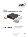
M2800 USB Bar Code and Magnetic Card Reader User’s Manual © 2005 American Microsystems LTD. Last Revision: May 10, 2005 Website: www.amltd.com Model M2800 USB Bar Code and Magnetic Card Reader 2005 American Microsystems, Ltd. All Rights Reserved 2190 Regal Parkway • Euless, TX 76040 Phone 817.571.9015 • Fax 817.571.6176 Web Address: www.amltd.com Page: 1 Regulatory Information All American Microsystems, Ltd. devices are designed to be compliant with rules and regulations in locations they are sold and will be labeled as required. Any changes or modifications to American Microsystems, Ltd. equipment, not expressly approved by American Microsystems, Ltd., could void the user's authority to operate the equipment. Disclaimer American Microsystems, Ltd. reserves the right to make changes in specifications and other information contained in this document without prior notice, and the reader should in all cases consult American Microsystems, Ltd. to determine whether any such changes have been made. The information in this publication does not represent a commitment on the part of American Microsystems, Ltd. American Microsystems, Ltd. shall not be liable for technical or editorial errors or omissi ons contained herein; nor for incidental or consequential damages resulting from the furnishing, performance, or use of this material. This document contains proprietary information that is protected by copyright. All trademarks or registered trademarks of other companies are used only for explanation without intent to infringe. All rights are reserved. No part of this document may be photocopied, reproduced, or translated into another language without the prior written consent of American Microsystems, Ltd. FCC Declaration of Conformity Product Name: M2800 USB Bar Code and Magnetic Card Reader Model Number: M2800 Radio Frequency Interference Requirements This equipment complies with Part 15 of the FCC rules. Operation is subject to the following two conditions: (1) This equipment may not cause harmful interference, and (2) this equipment must accept any interference received, including interference that may cause undesired operation. This equipment has been tested and found to comply with the limits for a Class B digital device, pursuant to Part 15 of the FCC Rules. These limits are designed to provide reasonable protection against harmful interference when the equipment is operated in a residential environment. This equipment generates uses and can radiate radio frequency energy, and if not installed and used in accordance with the instructions, may cause harmful interference to radio communications. However, there is no guarantee that interference will not occur in a particular installation. If you determine the equipment does cause harmful interference to radio or television reception (this may be determined by monitoring the interference while turning the equipment off and on), you are encouraged to try to correct the interference by one of the following measures: • Reorient or relocate the receiving antenna. • Increase the separation between the equipment and receiver. • Connect the equipment into an outlet on a circuit different from that to which the receiver is connected. • Consult the dealer or an experienced radio or TV technician for help. Radio Frequency Interference Requirements - Canada This Class B digital apparatus complies with Canadian ICES-003. Cet appareil numérique de la classe B est conforme à la norme NMB-003 du Canada. Marking and European Economic Area (EEA) Products intended for sale within the European Union are marked with the CE mark that indicates compliance to applicable Directives and European Normes (EN), as follows. Amendments to these Directives or EN’s are included. • • Electromagnetic Compatibility Directive 89/336/EEC Low Voltage Directive 73/23/EEC Model M2800 USB Bar Code and Magnetic Card Reader 2005 American Microsystems, Ltd. All Rights Reserved 2190 Regal Parkway • Euless, TX 76040 Phone 817.571.9015 • Fax 817.571.6176 Web Address: www.amltd.com Page: 2 TABLE OF CONTENTS Introduction ......................................................................................................................... 4 Features .............................................................................................................................. 4 Installation Instructions........................................................................................................ 5 Default Settings................................................................................................................... 6 Changing the Default Settings............................................................................................. 8 Programming Guide ............................................................................................................ 9 Code 39.................................................................................................................... 10 UPC.......................................................................................................................... 10 EAN .......................................................................................................................... 11 UPC/EAN Supplements............................................................................................. 11 Interleaved 2 of 5..................................................................................................... 11 Codabar................................................................................................................... 12 Code 128/EAN-128 .................................................................................................... 12 Code 93.................................................................................................................... 12 Code 11.................................................................................................................... 13 MSI/Plessey.............................................................................................................. 13 RSS Symbologies ................................................................................................... 13 Serial Port Menu #1 ................................................................................................ 14 Serial Port Menu #2 ................................................................................................ 15 Mag. Stripe Menu #1 ............................................................................................... 15 Mag. Stripe Menu #2 ............................................................................................... 16 Preamble ................................................................................................................. 17 Postamble................................................................................................................ 18 Termination Character............................................................................................. 19 Scan Beep Tone ..................................................................................................... 19 Bar Code Edit........................................................................................................... 19 Bar Code Options..................................................................................................... 20 Laser / CCD Options................................................................................................. 20 Transmit Speed........................................................................................................ 21 Diagnostics............................................................................................................... 21 RS-232C Serial Port ............................................................................................................. 21 Connecting an Electronic Scale to the M2800...................................................................... 22 Specifications...................................................................................................................... 23 Signal Definition.................................................................................................................. 24 Function/Special Keys......................................................................................................... 25 Transaction Card Data Format............................................................................................. 26 Model M2800 USB Bar Code and Magnetic Card Reader 2005 American Microsystems, Ltd. All Rights Reserved 2190 Regal Parkway • Euless, TX 76040 Phone 817.571.9015 • Fax 817.571.6176 Web Address: www.amltd.com Page: 3 INTRODUCTION The Model 2800 USB bar code and magnetic stripe reader combines features found in a variety of readers into one compact, easy to use system. The M2800’s USB interface functions as a USB HID keyboard emulator, and will appear on the connected PC as an HID keyboard device. No custom USB drivers are required, as all USB HID drivers are included with Microsoft Windows®. Input data is sent to the PC as though it was typed in directly from the keyboard. The M2800 accepts a wide variety of input devices such as laser, CCD, wand, magnetic stripe reader, slot reader, and RS-232 serial input. The RS232 interface is mainly used as an input, but resembles a serial port found on a standard PC. The RS232 port is meant to connect serial input devices using a null-modem cable. The M2800 functions well as an RS232 serial to keyboard converter. Custom bar code decoding algorithms are used, imbuing the M2800 with the ability to read the most poorly printed barcodes, even ones not typically readable by other systems. The M2800 is capable of reading EAN, UPC, and all RSS symbologies and so is compliant with Global Tracking Identification Number (GTIN) requirements. The magnetic card reader performance exceeds that of the typical reader, supporting bi-directional swipes, and is tolerant of either very rapid or extremely slow swipes. The M2800 system is pre-configured to meet the needs of most users, but you may customize the M2800 to your individual application by changing the default settings using the M2800 setup menu barcode sheet. Robust construction, ease of use, and the quality of features make the Model 2800 an ideal data collection device for retail, industrial, or any data tracking application. FEATURES • Bar Code, Magnetic Card, and Serial Data appear as Keyboard Input to the PC. • Decoder automatically recognizes and reads the following bar code types: Code 39 Extended Code 39 (Full ASCII) UPC-A, UPC-E(0), UPC-E(1) EAN-8, EAN-13 UPC & EAN Supplements (2 and 5 character) Interleaved 2 of 5 Codabar Code 128 / EAN-128 Code 93 Code 11 MSI/Plessey RSS14 (Both Linear and Stackable Types) RSS Limited RSS Expanded (Both Linear and Stackable Types) • • • • Power/Ready Light Indicates Scanner Status Reads Single/Dual Track Magnetic Cards of all Standard Track Formats (Credit Cards, ID Cards, etc.) Supports Practically Any 5 Volt Undecoded Bar Code Input Device (Laser, CCD, Wand, Slot Reader) Accepts Data from the RS-232 Input Port (Electronic Scales, Portable Terminals, etc.) Model M2800 USB Bar Code and Magnetic Card Reader 2005 American Microsystems, Ltd. All Rights Reserved 2190 Regal Parkway • Euless, TX 76040 Phone 817.571.9015 • Fax 817.571.6176 Web Address: www.amltd.com Page: 4 INSTALLATION INSTRUCTIONS M2800 installation requires connecting the USB cable to your computer and connecting the necessary input devices. Step 1: Before plugging the M2800 into your PC’s USB port, if using Windows 98/98SE®, make sure you have your Microsoft Windows® installation CD available (needed for the first time only). For Windows 2000/ME/XP®, the system already has all needed USB HID drivers pre-installed. Step 2: With Windows® running, connect the USB cable to the PC and to the M2800 USB interface. Follow any instructions Windows® asks you to, if needed. Step 3: If the M2800 has been “enumerated” you will hear a series of beeps and the LED will be GREEN. Repeat Step 2 for every USB port on your computer, as Windows® treats every USB port in the system individually. This also applies if using a USB hub device. The use of a self-powered USB hub is also recommended, but not required. NOTE: DO NOT USE USB EXTENSION CABLES with the M2800. The USB standard was designed for keyboard cables with a length of 3 meters maximum. Use of a long USB extension cable may cause improper operation. If extra cable length is needed, the use of a USB hub device is required. Step 4: Connecting Input Devices: Installing a wand: Plug the end of the 5-pin wand cable into the circular connector labeled WAND on the front panel of the reader. If using a 9-pin wand, connect it to the 9-pin laser input on the front panel. Installing a laser scanner: Plug the end of the laser cable into the 9-pin connector labeled LASER located on the front panel of the reader. Installing a CCD scanner: Plug the end of the CCD cable into the connector labeled LASER located on the front panel of the reader. Installing a Magnetic Card/Stripe Reader: For a magnetic stripe reader with an 8-pin DIN connector, plug the connector into the circular connector labeled MSR on the front panel of the M2800. Single or dual-track magnetic readers can be used. Installing a Slot Reader (Badge Reader): Plug the end of the slot reader cable into the circular connector labeled WAND on the front panel of the M2800. Installing an RS232 serial device: Connect the RS232 plug into the M2800 RS232 port located on the rear panel. The connector is a standard RS232 9-pin. The RS232 cable of the connected device should implement null-modem, and should not be a straight pass-through cable. Model M2800 USB Bar Code and Magnetic Card Reader 2005 American Microsystems, Ltd. All Rights Reserved 2190 Regal Parkway • Euless, TX 76040 Phone 817.571.9015 • Fax 817.571.6176 Web Address: www.amltd.com Page: 5 DEFAULT SETTINGS The M2800 is shipped from the factory with the following default settings: Code 39 Code 39 Decoder Full ASCII Mod 43 Check Digit Send Check Digit Concatenate Mode ON OFF OFF OFF OFF EAN EAN Decoder Zero Fill EAN-8 to EAN-13 Send EAN-13 Country Code Send EAN-8 Country Code Send EAN-13 Check Digit Send EAN-8 Check Digit ISBN Conversion ON OFF ON ON ON ON OFF INTERLEAVED 2 of 5 I 2 of 5 Decoder Check Digit Send Check Digit Fixed Length Set Fixed Length #1 Set Fixed Length #2 ON None OFF OFF 06 00 CODE 93 Code 93 Decoder Concatenate Mode ON OFF CODE 128 / EAN-128 Code 128 Decoder UCC-128 Verification Send Mod 10 Check Digit Send EAN-128 ID EAN-128 GS Character ON OFF ON OFF GS MSI/PLESSEY MSI/Plessey Decoder Two Check Digits Required First Check Digit Mod 11 st Send 1 Check Digit nd Send 2 Check Digit ISBN Plessey OFF OFF OFF OFF OFF OFF PREAMBLE Enter Preamble Preamble Send Delay Active Types OFF 0.0 sec ALL UPC UPC Decoder Convert UPC-E to UPC-A Convert UPC-A to EAN-13 Send UPC-A Number System Send UPC-E Number System Send UPC-A Check Digit Send UPC-E Check Digit ON OFF OFF ON ON ON ON UPC/EAN SUPPLEMENTS Supplements Decoder Allow 2 Digit Supplements Allow 5 Digit Supplements Require Supplements Send Separator Space OFF ON ON None OFF CODABAR Codabar Decoder Send Start/Stop CLSI Formatting CLSI Check Digit ON OFF OFF OFF RSS SYMBOLOGIES RSS14 Decoder ON RSS Limited Decoder OFF RSS Expanded OFF Send EAN Type Identifier Send Application ID (AI) ON Send Linkage ID OFF Send Check Digit ON CODE 11 Code 11 Decoder Two Check Digits Required st Send 1 Check Digit nd Send 2 Check Digit OFF OFF OFF OFF POSTAMBLE Enter Preamble Postamble Send Delay Active Types OFF 0.0 sec ALL Model M2800 USB Bar Code and Magnetic Card Reader 2005 American Microsystems, Ltd. All Rights Reserved 2190 Regal Parkway • Euless, TX 76040 Phone 817.571.9015 • Fax 817.571.6176 Web Address: www.amltd.com OFF Page: 6 BAR CODE OPTIONS Send Bar Code Type ID Duplicate Reads Allowed Bar Code Function Keys Bar Code Special Keys Term Char Override OFF ON OFF ON OFF SERIAL PORT #1 Mode Protocol (Flow Control) Use Record Term. Char. Send Record Term Char. Enter Record Term Char. Timeout Delay Serial Command String Serial Special/Function Keys 0=Batch 0=None OFF OFF CR (ASCII 13) 0.0 OFF ON MAG STRIPE #1 Send Account Number Send Name (Track 1 only) Send Expiration Date Send All Track Data Enter Track 1 Sep. Char. Format Exp. Date MMYY Enter Track 2&3 Sep. Char. ON ON ON ON “^” OFF “=” SCAN BEEP Length: Tone: 1) Medium Short 6) Medium High BAR CODE EDIT Bar Code Editing Enter # of Leading Chars to Strip Enter # of Trailing Chars to Strip Enter Bar Code Type to Edit Strip Leading and Trailing Spaces OFF 0 0 ALL OFF LASER/CCD OPTIONS Laser Trigger Mode Laser/CCD Timeout Read Delay Read Verification 0 3 sec 0.0 sec 0 SERIAL PORT #2 Baud Rate (9600 baud) Parity/Data Size (None, 8, 1) 3 5 MAG STRIPE #2 Output Require Two Tracks ` Send Start & End Sentinels Between Track/Field Term. Char Send Ending Term. Char. Strip Spaces Mag Stripe Code Special Keys 2=Both OFF OFF OFF ON ON OFF TERMINATION CHARACTER 2) Carriage Return CR (ASCII 13) TRANSMIT SPEED 3) Fast Model M2800 USB Bar Code and Magnetic Card Reader 2005 American Microsystems, Ltd. All Rights Reserved 2190 Regal Parkway • Euless, TX 76040 Phone 817.571.9015 • Fax 817.571.6176 Web Address: www.amltd.com Page: 7 CHANGING THE DEFAULT SETTINGS You can easily change the default settings by simply scanning the bar code options located on the M2800 Setup Menu. The M2800 Setup Menu is a sheet of bar codes supplied for use with the M2800. If a replacement is needed, both the M2800 User’s Manual and M2800 Setup Menu are available at www.amltd.com in Adobe Acrobat® PDF format. A full description of each customizable option can be found in the Programming Guide, under its respective menu heading. The basic programming sequence is: START / CATEGORY / OPTION (0-9) / ON/OFF (or) NUMBER(s) ONLY / EXIT Follow the instructions below to change the settings. Step 1: Scan the START label at the top left corner of the M2800 Setup Menu. This puts the M2800 into the program mode. Step 2: Scan one of the Category labels (i.e. Code 39, UPC, Baud Rate). Step 3: Select the desired option by scanning one of the numeric labels (0 - 9). Step 4: If there is an (ON/OFF) next to the description, scan the ON label to enable or the OFF label to disable the option. Example: To enable the MOD 43 check digit on Code 39, perform the following: 1) Scan the Code 39 category label. 2) Scan the option (2) label to select the MOD 43 check digit option. 3) Scan the ON label to enable option (2). If there is a range of numbers next to the option, then scan one of the numeric labels (0 - 9). Example: To select the OPCC check digit for Interleaved 2 of 5, perform the following: 1) Scan the Int. 2 of 5 category label. 2) Scan the (1) label to select the check digit option. 3) Scan the numeric 2 label to select OPCC. Step 5: If you want to make another change within the same category, you can scan another option number (i.e., return to step 3 above). If you want to make a change in a different category you must scan the new category (i.e., return to step 2 above and repeat the steps). Step 6: When you have finished making all of the changes, you can either: 1) Scan the EXIT (Save Changes) label to save all the changes or 2) Scan the EXIT (Ignore Changes) label to exit without saving any changes. NOTE: You can reset the M2800 to the default setting by performing the following: 1) Scan the START label. 2) Scan the RESET ALL DEFAULTS label. 3) Scan the EXIT (Save Changes) label. Model M2800 USB Bar Code and Magnetic Card Reader 2005 American Microsystems, Ltd. All Rights Reserved 2190 Regal Parkway • Euless, TX 76040 Phone 817.571.9015 • Fax 817.571.6176 Web Address: www.amltd.com Page: 8 PROGRAMMING GUIDE START The START bar code places the M2800 into the program mode. After scanning this label, the M2800 will emit three short beeps to indicate that it is in the program mode. EXIT (SAVE CHANGES) Scan this bar code to EXIT the program mode and save all of the changes. After scanning this label, the M2800 will beep twice then delay approximately one second and emit three short beeps to indicate that it accepted the changes. EXIT (IGNORE CHANGES) Scan this bar code to EXIT the program mode and discard all of the current changes. The M2800 will use the settings that were in effect before entering the program mode. RESET ALL DEFAULTS Scan this bar code to reset all options to their default settings. NOTE: Defaults are marked with an asterisk (*). 0-9 BAR CODES These bar codes are scanned to select various options and enter programmable data into the M2800. NOTE: Scan option 9 to reset all of the options within the current category back to their defaults. ON If the OPTION has an (ON/OFF) beside the description, scan the ON bar code to turn on the current option. OFF If the OPTION has an (ON/OFF) beside the description, scan the OFF bar code to turn off the current option. FULL ASCII CHART The Full ASCII Chart is located on the back of the M2800 Setup Menu. This chart contains the entire ASCII character set (128 characters). Use this chart to enter Preamble and Postamble character strings as well as the Record Terminator and Separator characters. ADDITIONAL NOTES: If the description beside the option contains: (ON/OFF) Scan either an ON or OFF label to set the option. (CHART) Scan one or more characters from the Full ASCII Chart. (0 – 9) Scan the desired character from the 0-9 labels. (0.0 – 9.9) Scan two characters from the 0-9 labels to set the time from 0 to 9.9 seconds. Model M2800 USB Bar Code and Magnetic Card Reader 2005 American Microsystems, Ltd. All Rights Reserved 2190 Regal Parkway • Euless, TX 76040 Phone 817.571.9015 • Fax 817.571.6176 Web Address: www.amltd.com Page: 9 CODE 39 0) CODE 39 DECODER ON* Enable reading Code 39 labels. OFF Disable reading Code 39 labels. 1) FULL ASCII ON Enable the Full ASCII Extension to Code 39. Option #0 above must be set on. OFF* Disable the Full ASCII Extension to Code 39. This sets the M2800 to the standard Code 39 mode. 2) MOD 43 CHECK DIGIT ON Enable the Mod 43 Check Digit for Code 39. When this option is enabled, only Code 39 labels that contain a valid check digit will be read. OFF* Disable the Mod 43 Check Digit. Check digit verification will not be performed. 3) SEND CHECK DIGIT ON Transmit the Mod 43 Check Digit with the bar code data. Requires option #2 above to be set on. OFF* Do not transmit the Mod 43 Check Digit. 4) CONCATENATE MODE ON Enable Concatenate Mode. The concatenate mode allows the M2800 to accumulate multiple bar codes in its buffer, and then sends them to the computer just like they were a single bar code. When a Code 39 label containing a leading space is read, the M2800 emits two short beeps and buffers the data without transmission. This process continues until a Code 39 label without a leading space is read or 128 characters are buffered. A Code 39 bar code label that only contains a single or multiple dashes (minus sign) will clear the buffer. OFF* Disable Concatenate Mode. UPC 0) UPC DECODER ON* Enable reading UPC-A and UPC-E labels. OFF Disable reading UPC-A and UPC-E labels. 1) CONVERT UPC-E TO UPC-A ON Convert all UPC-E labels to their UPC-A equivalents (zero-fill) before transmission. After conversion, the M2800 will follow the UPC-A programming options. OFF* No conversions will be performed. 2) CONVERT UPC-A TO EAN-13 ON Convert all UPC-A labels to an equivalent EAN-13 format by inserting a leading zero. After conversion, the M2800 will follow the EAN-13 programming options. OFF* No conversions will be performed. 3) SEND UPC-A NUMBER SYSTEM ON* Transmit the UPC-A Number System character. OFF Do not transmit the UPC-A Number System character. 4) SEND UPC-E NUMBER SYSTEM ON* Transmit the UPC-E Number System character. OFF Do not transmit the UPC-E Number System character. 5) SEND UPC-A CHECK DIGIT ON* Transmit the UPC-A Check Digit character. OFF Do not transmit the UPC-A Check Digit character. 6) SEND UPC-E CHECK DIGIT ON* Transmit the UPC-E Check Digit character. OFF Do not transmit the UPC-E Check Digit character. Model M2800 USB Bar Code and Magnetic Card Reader 2005 American Microsystems, Ltd. All Rights Reserved 2190 Regal Parkway • Euless, TX 76040 Phone 817.571.9015 • Fax 817.571.6176 Web Address: www.amltd.com Page: 10 EAN 0) EAN DECODER ON* Enable reading EAN-8 and EAN-13 labels. OFF Disable reading EAN-8 and EAN-13 labels. 1) ZERO FILL EAN-8 TO EAN-13 ON Add five leading zeroes to EAN-8 labels. After conversion, the M2800 will follow the EAN-13 programming options. OFF* No conversion is performed. 2) SEND EAN-13 COUNTRY CODE ON* Transmit the EAN-13 Country Code. OFF Do not transmit the EAN-13 Country Code. 3) SEND EAN-8 COUNTRY CODE ON* Transmit the EAN-8 Country Code. OFF Do not transmit the EAN-8 Country Code. 4) SEND EAN-13 CHECK DIGIT ON* Transmit the EAN-13 Check Digit character. OFF Do not transmit the EAN-13 Check Digit character. 5) SEND EAN-8 CHECK DIGIT ON* Transmit the EAN-8 Check Digit character. OFF Do not transmit the EAN-8 Check Digit character. 6) ISBN CONVERSION ON Convert 13 digit Bookland/EAN (978 prefix) to its corresponding 10 digit ISBN number. EXAMPLE: BAR CODE DATA = 9780806957906 ISBN OUTPUT DATA = 0806957905 OFF* Do not convert Bookland/EAN to an ISBN number. UPC/EAN SUPPLEMENTS 0) SUPPLEMENTS DECODER ON Enable reading UPC & EAN supplements. OFF* Disable reading UPC & EAN supplements. 1) ALLOW 2 DIGIT ON* Enable reading 2 digit supplements. Option 0 above must be set on. OFF Disable reading 2 digit supplements. 2) ALLOW 5 DIGIT ON* Enable reading 5 digit supplements. Option 0 above must be set on. OFF Disable reading 5 digit supplements. 3) REQUIRE SUPPLEMENTS Specifies how the M2800 will handle various supplements. 0)* None: UPC/EAN bar codes will be read with or without valid supplements. 1) UPC bar codes will not be read unless they are accompanied by a valid supplement. 2) EAN bar codes will not be read unless they are accompanied by a valid supplement. 3) Bookland EAN bar codes will not be read unless they are accompanied by a valid supplement. 4) All UPC/EAN bar codes will not be read unless they are accompanied by a valid supplement. 4) SEND SEPARATOR SPACE ON Insert a space between the standard bar code data and the supplemental data. OFF* No separator space is inserted. INTERLEAVED 2 OF 5 0) I 2 OF 5 DECODER ON* Enable reading Interleaved 2 of 5 labels. OFF Disable reading Interleaved 2 of 5 labels. 1) Check Digit: 0=None, 1=USS, 2=OPCC Specifies which type of check digit will be used with Interleaved 2 of 5: 0)* None (no check digit required) 1) Uniform Symbology Specification (USS) (3-1-3 Mod 10) 2) Optical Product Code Council (OPCC) (2-1-2 Mod 10) Model M2800 USB Bar Code and Magnetic Card Reader 2005 American Microsystems, Ltd. All Rights Reserved 2190 Regal Parkway • Euless, TX 76040 Phone 817.571.9015 • Fax 817.571.6176 Web Address: www.amltd.com Page: 11 2) SEND CHECK DIGIT ON Transmit the Interleaved 2 of 5 check digit with the bar code data. OFF* The check digit is not transmitted. 3) FIXED LENGTH ON Read only fixed length Interleaved 2 of 5 bar code labels that match the lengths defined in options 4 & 5 below. The check digit can be on or off. OFF* Disable Fixed Length mode. Read all Interleaved 2 of 5 labels without regard to length. 4) SET FIXED LENGTH #1 (02-60) Sets the first valid fixed length for Interleaved 2 of 5. Scan a two digit value to enter the length. Valid lengths are 02 to 60 characters. By definition, the length of Interleaved 2 of 5 labels are an even number of characters. The default fixed length is 6 characters. 5) SET FIXED LENGTH #2 (02-60) Sets a second valid fixed length for Interleaved 2 of 5. Scan a two digit value to enter the length. The default length is set to 0 characters (i.e. the second fixed length is disabled). CODABAR 0) CODABAR DECODER ON * Enable reading Codabar labels. OFF Disable reading Codabar labels. 1) SEND START/STOP ON Transmit the Codabar start/stop characters. OFF * Do not transmit the Codabar start/stop characters. 2) CLSI FORMATTING ON The M2800 will insert a blank after the 1st, 5th, and 10th characters of a 14-character Codabar label. The label length does not include the start and stop characters. OFF* Disable CLSI formatting. 3) CLSI CHECK DIGIT ON Enable the CLSI check digit. When this option is enabled, all fourteen digit numeric bar codes must contain a valid check digit. OFF* Disable the CLSI check digit. Check digit verification will not be performed. CODE 128 / EAN-128 0) CODE 128 DECODER ON * Enable reading Code 128 labels. OFF Disable reading Code 128 labels. 1) UCC-128 VERIFICATION ON A valid mod 10 check digit is required on UCC-MOD 10 bar codes. (Applies to 20-digit serial shipping container bar codes.) OFF * UCC-MOD 10 bar codes are accepted without valid mod check digit. 2) SEND MOD 10 CHECK DIGIT ON * Transmit the mod 10 check digit with the bar code entry. OFF Do not transmit the mod 10 check digit. 4) SEND EAN-128 ID ON Send EAN-128 EAN type identifier ]C1 OFF * Do not send EAN-128 EAN type identifier 5) EAN-128 GS CHARACTER (CHART) The group separator (<GS>, ASCII 29) is used by EAN-128 to separate sub-strings within a larger bar code, and is most commonly used on postal shipping labels. This character can be mapped to any ASCII character using the chart. (Default = GS) Model M2800 USB Bar Code and Magnetic Card Reader 2005 American Microsystems, Ltd. All Rights Reserved 2190 Regal Parkway • Euless, TX 76040 Phone 817.571.9015 • Fax 817.571.6176 Web Address: www.amltd.com Page: 12 CODE 93 0) CODE 93 DECODER ON* Enable reading Code 93 labels. OFF Disable reading Code 93 labels. 1) CONCATENATE MODE ON Enable Concatenate Mode. The concatenate mode allows the M2800 to concatenate multiple bar codes in its buffer, then send them to the computer just like they were a single bar code. When a Code 93 label with a leading space is read, the M2800 emits two short beeps and buffers the data without transmission. This process continues until a Code 93 label without a leading space is read or 128 characters are buffered. A Code 93 bar code label that only contains a single or multiple dashes (minus sign) will clear the buffer. OFF* Disable Concatenate Mode. CODE 11 0) CODE 11 DECODER ON Enable reading Code 11 labels. OFF * Disable reading Code 11 labels. 1) TWO CHECK DIGITS REQUIRED ON Two valid check digits are required for each label. OFF * One valid check digit is required for each label. 2) SEND FIRST CHECK DIGIT ON Transmit the first check digit. OFF * Do not transmit the first check digit. 3) SEND SECOND CHECK DIGIT ON Transmit the second check digit. OFF * Do not transmit the second check digit. MSI/PLESSEY 0) MSI/PLESSEY DECODER ON Enable reading MSI/Plessey labels. OFF * Disable reading MSI/Plessey labels. 1) TWO CHECK DIGITS REQUIRED ON Two valid check digits are required for each label. The first check digit is defined by option 2 below. The second check digit is always mod 10. OFF * One valid check digit is required for each label. The check digit must be mod 10. 2) FIRST CHECK DIGIT MOD 11 ON The first check digit must be mod 11. OFF * The first check digit must be mod 10. 3) SEND FIRST CHECK DIGIT ON Transmit the first check digit. OFF * Do not transmit the first check digit. 4) SEND SECOND CHECK DIGIT ON Transmit the second check digit. OFF * Do not transmit the second check digit. 5) ISBN PLESSEY ON Enable reading of Modified Plessey ISBN bar codes. Only eleven digit ISBN bar codes will be read. OFF* Do not read Modified Plessey ISBN bar codes. Model M2800 USB Bar Code and Magnetic Card Reader 2005 American Microsystems, Ltd. All Rights Reserved 2190 Regal Parkway • Euless, TX 76040 Phone 817.571.9015 • Fax 817.571.6176 Web Address: www.amltd.com Page: 13 RSS SYMBOLOGIES 0) RSS14 Decoder (both Linear and Stackable types) ON* Enable reading RSS14 labels. OFF Disable reading RSS14 labels. 1) RSS Limited Decoder ON Enable reading RSS Limited labels. OFF* Disable reading RSS Limited labels. 2) RSS Expanded Decoder (both Linear and Stackable types) ON Enable reading RSS Expanded labels. OFF* Disable reading RSS Expanded labels. 3) Send EAN Type Identifier (applies to all: RSS14, RSS Limited, RSS Expanded) ON Send EAN type identifier ([e0) before barcode OFF* Do not send EAN type identifier 4) Send Application Id (AI) (applies to all: RSS14, RSS Limited, RSS Expanded) ON* Send Application ID (01) before barcode OFF Do not send Application ID 5) Send Linkage Digit (applies to all: RSS14, RSS Limited, RSS Expanded) Note: This feature is not officially part of the RSS spec. It allows a flag (yes=1 or no=0) to be sent if the RSS bar code is part of a composite 2D bar code. Does not decode the 2D composite portion of the bar code. ON Send the Linkage Digit OFF* Do not send the Linkage Digit 6) Send Check Digit (applies to all: RSS14, RSS Limited, RSS Expanded) ON* Send the Check Digit OFF Do not send the Check Digit SERIAL PORT #1 The M2800's RS-232 serial port accepts serial input data and re-transmits it to the computer through the keyboard interface. 0) MODE: 0=BATCH, 1=PASS THROUGH This option selects the mode of operation for serial input port. 0)* Selects the Batch Mode of operation. The M2800 buffers the data until it finds a valid record terminator character or a timeout occurs. The serial buffer can contain a maximum of 256 characters. The serial Preamble and Postamble can be used. (See options 2, 3, 4, and 5 for more information on Record Terminator and Timeout Delay.) 1) Selects the Pass Through Mode of operation. The M2800 simply transmits each character that it receives from the serial port to the computer. Note that with MODE 1, the Preamble, Postamble, record terminator character, and timeout delay are not used. 1) PROTOCOL: 0=NONE, 1=XON/XOFF 0)* No flow control protocol is used. The serial buffer can contain a maximum of 256 characters. 1) XON/XOFF Protocol is selected. In this mode, the M2800 will transmit an XOFF (control S) character to stop incoming serial data. This prevents the serial buffer from overflowing. Once the M2800 has finished typing and is ready to accept more data, an XON (control Q) character will be transmitted to enable reception of more serial data. The XOFF will be transmitted when the buffer fills to 128 characters. Model M2800 USB Bar Code and Magnetic Card Reader 2005 American Microsystems, Ltd. All Rights Reserved 2190 Regal Parkway • Euless, TX 76040 Phone 817.571.9015 • Fax 817.571.6176 Web Address: www.amltd.com Page: 14 2) RECORD TERMINATOR CHAR ON Valid only if option 0 is set for Batch Mode. The M2800 will search for the record terminator character, defined with option 4, which indicates the end of the data. There are two ways to trigger the transmission of the serial data buffer: (1) the M2800 detects the record terminator character or, (2) a timeout occurs. OFF* The M2800 will wait for a timeout before sending the serial data buffer out the keyboard interface. No check will be made for a record terminator character. 3) SEND RECORD TERMINATOR CHAR ON Transmit the record terminator character along with the serial data buffer. OFF* Do not transmit the record terminator character. Send only the serial data buffer. 4) ENTER RECORD TERMINATOR CHAR This option valid only if option 0 is set to Batch Mode and option 2 is enabled. The record terminator character can be scanned from the Full ASCII Chart on the back of the menu. This character is used to identify the end of the serial data stream. Once the M2800 detects this character, the buffered data is transmitted in a block to the computer through the keyboard interface. The default is a Carriage Return. 5) TIMEOUT DELAY (0.0 - 9.9 SEC) This parameter defines the maximum period allowed to elapse before the M2800 assumes the transmission has ended. The timer is activated on receipt of the first character from the serial input port. Any incoming character that arrives before the timeout occurs will reset the timer. The timeout delay can be programmed from 0.0 to 9.9 seconds in increments of 0.1 seconds. The default setting is 0.0 seconds. (To select a value, for example, 2.0, scan the 2 label, then the "0" label.) NOTE: Timeout Delay is used as a host response timeout delay when host response mode is enabled, at which point, the delay is from 0-99 seconds. 6) ENTER SERIAL COMMAND STRING This option allows bar code data to be redirected out the serial port instead of the keyboard interface. When the start of the bar code data matches the Command String, the M2800 will strip the Command String from the bar code data and then transmit the remaining data out the serial port instead of the keyboard interface. This feature is especially useful for interrogating electronic scales with RS-232C serial interfaces. To define this Command String, scan up to 5 characters from the Full ASCII Chart on the M2800 Setup Menu and then scan the ON bar code when finished, or scan OFF to erase or disable the string. 7) Serial Data Special/Function Keys ON* This option allows some non-printable ASCII data to be sent as PC keyboard keys. See Special/Function keys for a description of implementation. For example: converts ASCII 13 (CR) to USB Enter Key. OFF No conversion, key sent as CTRL-Shift-ASCII (i.e. Ctrl-Shift-M for CR) SERIAL PORT #2 BAUD RATE The baud rate sets the data transmission speed for the serial input port on the M2800. The M2800’s baud rate must match the serial input device (electronic scale, portable terminal, etc.). Select one of the following: 0) 1200 1) 2400 2) 4800 3)* 9600 4) 19,200 Model M2800 USB Bar Code and Magnetic Card Reader 2005 American Microsystems, Ltd. All Rights Reserved 2190 Regal Parkway • Euless, TX 76040 Phone 817.571.9015 • Fax 817.571.6176 Web Address: www.amltd.com Page: 15 PARITY Sets the parity for the incoming serial data. This setting must match the serial input device (electronic scale, portable terminal, etc.). Select one of the following: 5)* N,8,1: None, 8 data bits, 1 Stop bit 6) E,7,1: Even, 7 data bits, 1 Stop bit 7) O,7,1: Odd, 7 data bits, 1 Stop bit 8) M,7,1: Mark, 7 data bits, 1 Stop bit MAG STRIPE OPTIONS #1 0) Send Account Number (valid only if option 3 is OFF) ON* Transmit the Account Number data from the magnetic card. On major credit cards, the account number is available on tracks 1 and 2. OFF Do not send the account information 1) Send name (valid only if option 3 is OFF) ON* Transmit the Name data on the magnetic card. The name is available only on Track 1. OFF Do not transmit name 2) Send Expiration Date (valid only if option 3 is OFF) ON* Send expiration date OFF Do not send expiration date. 3) Send All Track Data ON* Transmit ALL the data from each enabled track. The data is transmitted as it appears on the card with NO formatting; however, separator characters will be inserted between the fields. See options 4 and 6 for information on separator characters. OFF Disables this option 4) Enter the Track 1 Separator Character (valid only with option 3 ON) Chart Send the Separator Character. This separates the fields found when decoding a track in the Track 1 format. It is selectable from the full-ASCII menu chart. The default is “^”. 5) Format Expiration Date MMYY (valid only with option 3 OFF) ON Expiration date sent as MMYY OFF* Expiration date sent as YYMM 6) Enter Tracks 2 and 3 Separator Characters Chart Send the Separator Character. This separates the fields found when decoding a track in the Track 2 or 3 formats. It is selectable from the full-ASCII menu chart. The default is “=”. MAG STRIPE OPTIONS #2 0) Output This option designates which track(s) will be output, and in what order. You may use a dual-track decoder in a single-track application by selecting FIRST TRACK (only) or SECOND TRACK (only). Select one of the following: 0) 1) 2)* 3) First Track (only) Second Track (only) Both Tracks (output in order) Both Tracks (reverse order) Note: The M2800 can auto-discriminate track data formats. It can read Track 1, Track 2, or Track 3 formats on the FIRST TRACK. It can also read Track 2 and Track 3 formats on the SECOND TRACK. Model M2800 USB Bar Code and Magnetic Card Reader 2005 American Microsystems, Ltd. All Rights Reserved 2190 Regal Parkway • Euless, TX 76040 Phone 817.571.9015 • Fax 817.571.6176 Web Address: www.amltd.com Page: 16 This would mean, for example, that a track 2 and 3 card would be read by the FIRST TRACK and SECOND TRACK, respectively. 1) Require Two Tracks ON Both tracks must decode successfully for a “good read” to occur. (Only valid for dual track readers) OFF* M2800 will accept one or more valid tracks as a “good read”. If OFF in a dual track application, it may allow a decode, even if only one track is successfully decoded. Use this setting for singletrack applications. 2) Send Start and End Sentinels (valid only if SEND ALL TRACK DATA is ON) ON* The Start/End sentinel characters for each enabled track will be transmitted. The characters for each enabled track will be transmitted. The characters for each type of sentinel are listed below: 1.) Track 1 start: “%” 2.) Track 2 and 3 start: “;” 3.) Track 1, 2, and 3 stop: “?” OFF Do not transmit the Start/End Sentinel characters. 3) Between Track/Fields Termination Character The Character to be output is defined from the Terminator Character option. The default is a carriage return (USB Enter Key). ON Transmit the Termination Character between each track/field that is read. The insertion location is according to the following: a) If the Send All Track Data option is ON, the character will be inserted between Tracks. b) If the Send All Track Data option is OFF, the character will be inserted between Fields. OFF * Do not transmit the Between Tracks/Fields Termination Character. 4) SEND ENDING TERMINATION CHARACTER The character to be output is defined from the Termination Character option. The default is a carriage return (ENTER). ON * Transmit the Termination Character after all data has been sent. OFF Do not transmit the Ending Termination Character. 5) STRIP SPACES (This option valid only if Send All Track Data is off.) ON * All spaces will be stripped from the Account Number Field, and any leading or trailing spaces will be stripped from the Name Field. OFF Do not strip any spaces from the mag stripe data. 6) Mag Stripe Data Special/Function Keys ON* This option allows some non-printable ASCII data to be sent as PC keyboard keys. See Special/Function keys for a description of implementation. For example: converts ASCII 13 (CR) to USB Enter Key. OFF No conversion, key sent as CTRL-Shift-ASCII (i.e. Ctrl-Shift-M for CR) PREAMBLE Preamble refers to a user-defined set of characters transmitted at the beginning of each type of input data. There are three different preambles with one set each for bar code data, magnetic stripe data, and serial input port data. 0) ENTER BAR CODE PREAMBLE This set of user-defined characters is transmitted at the beginning of bar code data. To define this preamble, scan up to 15 characters from the Full ASCII Chart on the reverse side of the M2800 Setup Menu. Scan the ON bar code when complete. Scan OFF to completely erase or disable the preamble. Model M2800 USB Bar Code and Magnetic Card Reader 2005 American Microsystems, Ltd. All Rights Reserved 2190 Regal Parkway • Euless, TX 76040 Phone 817.571.9015 • Fax 817.571.6176 Web Address: www.amltd.com Page: 17 1) ENTER MAG STRIPE PREAMBLE This set of user-defined characters is transmitted at the beginning of mag stripe data. To define this preamble, scan up to 15 characters from the Full ASCII Chart on the reverse side of the M2800 Setup Menu. Scan the ON bar code when complete. Scan OFF to completely erase or disable the preamble. 2) ENTER SERIAL PORT PREAMBLE This set of user-defined characters is transmitted at the beginning of serial port data. To define this preamble, scan up to 15 characters from the Full ASCII Chart on the reverse side of the M2800 Setup Menu. Scan the ON bar code when complete. Scan OFF to completely erase or disable the preamble. 3) BAR CODE SEND DELAY (0.0 - 9.9 SEC) This option specifies the amount of delay to occur after the bar code preamble is transmitted. The delay period is programmable from 0.0 to 9.9 seconds. 4) MAG SEND DELAY (0.0 - 9.9 SEC) This option specifies the amount of delay to occur after the mag stripe preamble is transmitted. The delay period is programmable from 0.0 to 9.9 seconds. 5) SERIAL SEND DELAY (0.0 - 9.9 SEC) This option specifies the amount of delay to occur after the serial port preamble is transmitted. The delay period is programmable from 0.0 to 9.9 seconds. 6) ACTIVE TYPES Specifies the types of bar codes that use preambles. Select one of the following: A Code 39 E EAN-8 I Code 93 B UPC-A F I 2 of 5 J MSI/Plessey C UPC-E G Codabar K Code 11 D EAN-13 H Code 128 L ISBN M RSS14 N RSS Limited O RSS Expanded X* All Bar Codes POSTAMBLE Postamble refers to a user-defined set of characters transmitted at the end of each type of input data. There are three different postambles with one set each for bar code data, magnetic stripe data, and serial input port data. 0) ENTER BAR CODE POSTAMBLE This set of user-defined characters is transmitted at the end of bar code data. To define this postamble, scan up to 15 characters from the Full ASCII Chart on the reverse side of the M2800 Setup Menu. Scan the ON bar code when complete. Scan OFF to completely erase or disable the postamble. 1) ENTER MAG STRIPE POSTAMBLE This set of user-defined characters is transmitted at the end of magnetic stripe code data. To define this postamble, scan up to 15 characters from the Full ASCII Chart on the reverse side of the M2800 Setup Menu. Scan the ON bar code when complete. Scan OFF to completely erase or disable the postamble. 2) ENTER SERIAL PORT POSTAMBLE This set of user-defined characters is transmitted at the end of serial port data. To define this postamble, scan up to 15 characters from the Full ASCII Chart on the reverse side of the M2800 Setup Menu. Scan the ON bar code when complete. Scan OFF to completely erase or disable the postamble. 3) BAR CODE SEND DELAY (0.0 - 9.9 SEC) This option specifies the amount of delay to occur after the bar code postamble is transmitted. The delay period is programmable from 0.0 to 9.9 seconds. Model M2800 USB Bar Code and Magnetic Card Reader 2005 American Microsystems, Ltd. All Rights Reserved 2190 Regal Parkway • Euless, TX 76040 Phone 817.571.9015 • Fax 817.571.6176 Web Address: www.amltd.com Page: 18 4) MAG SEND DELAY (0.0 - 9.9 SEC) This option specifies the amount of delay to occur after the mag stripe postamble is transmitted. The delay period is programmable from 0.0 to 9.9 seconds. 5) SERIAL SEND DELAY (0.0 - 9.9 SEC) This option specifies the amount of delay to occur after the serial port postamble is transmitted. The delay period is programmable from 0.0 to 9.9 seconds. 6) ACTIVE TYPES Specifies the types of bar codes that use postambles. Select one of the following: A Code 39 E EAN-8 I Code 93 M RSS14 B UPC-A F I 2 of 5 J MSI/Plessey N RSS Limited C UPC-E G Codabar K Code 11 O RSS Expanded D EAN-13 H Code 128 L ISBN X* All Bar Codes Model M2800 USB Bar Code and Magnetic Card Reader 2005 American Microsystems, Ltd. All Rights Reserved 2190 Regal Parkway • Euless, TX 76040 Phone 817.571.9015 • Fax 817.571.6176 Web Address: www.amltd.com Page: 19 TERMINATION CHARACTER The optional Termination Character is transmitted at the end of the data. If a user defined Termination Character is desired select option 4 below, then scan a single character from the Full ASCII section of the Setup Menu. 0) None 1) Horizontal Tab (ASCII 09) or (Special Keys On: USB Tab Key) 2)* Carriage Return (ASCII 13) or (Special Keys On: USB Enter Key) 3) USB Numeric Keypad Enter 4) User Defined Termination Character (from ASCII chart) SCAN BEEP Settings (0-3) set the length of the beep. Settings (4-7) set the tone (pitch) of the beep. Setting (8), when selected will override the other beep selections and shut the beep off. Length Tone 0) Short 4) Low 1) * Medium Short 5) Medium Low 2) Medium Long 6)* Medium High 3) Long 7) High 8) No Beep BAR CODE EDIT This option allows data editing (modification) before transmission. 0) DATA EDITING Must be on for any of the editing options below to be valid. ON: Enable Data Editing. OFF*: Disable Data Editing. 1) ENTER # OF LEADING CHAR TO STRIP (0-9, A-F) Refers to the number (0-15) of characters to be stripped or removed from the beginning of the bar code data. 2) ENTER # OF TRAILING CHAR TO STRIP (0-9, A-F) Refers to the number (0-15) of characters to be stripped or removed from the end of the bar code data. NOTE: If the total number of strip characters (both Leading and Trailing) is greater than the number of characters of the bar code, no characters will be stripped. 3) ENTER DATA TYPE TO EDIT Refers to the type of bar codes for which editing can be enabled, allowing editing to be specific to a type of bar code. The choices are listed below: A Code 39 E EAN-8 I Code 93 M RSS14 B UPC-A F I 2 of 5 J MSI/Plessey N RSS Limited C UPC-E G Codabar K Code 11 O RSS Expanded D EAN-13 H Code 128 L ISBN X* All Bar Codes 4) STRIP LEADING & TRAILING SPACES ON: Any Leading and Trailing Spaces will be stripped from the data. OFF*: No spaces will be stripped. Model M2800 USB Bar Code and Magnetic Card Reader 2005 American Microsystems, Ltd. All Rights Reserved 2190 Regal Parkway • Euless, TX 76040 Phone 817.571.9015 • Fax 817.571.6176 Web Address: www.amltd.com Page: 20 BAR CODE OPTIONS 0) SEND BAR CODE TYPE ID: (ON/OFF) ON: Sends a letter preceding the data, indicating the symbology type of the bar code. The letter corresponds to the types: A Code 39 E EAN-8 I Code 93 M RSS14 B UPC-A F I 2 of 5 J MSI/Plessey N RSS Limited C UPC-E G Codabar K Code 11 O RSS Expanded D EAN-13 H Code 128 L ISBN X* All Bar Codes OFF*: Do not transmit Bar Code Type ID 1) DUPLICATE READS ALLOWED (ON/OFF) ON*: Enable reading the same bar code multiple times. OFF: Disable reading the same bar code twice in a row. 2) BAR CODE FUNCTION KEYS (ON/OFF) ON: Function Keys F1 through F10 will be transmitted in place of the ASCII characters DC1 (17) through SUB (26). See Special/Function keys for a description of implementation. OFF*: Disable Function Keys. (Standard ASCII characters are transmitted.) 3) BAR CODE SPECIAL KEYS ON* This option allows some non-printable ASCII data to be sent as PC keyboard keys. See Special/Function keys for a description of implementation. For example: converts ASCII 13 (CR) to USB Enter Key. OFF No conversion, key sent as CTRL-Shift-ASCII (i.e. Ctrl-Shift-M for CR) 4) BAR CODE TERM CHAR OVERRIDE: (ON/OFF) ON: If any control character or special character (i.e., function key, arrow key, etc.) is embedded in the bar code data, the Termination Character, the Bar Code Preamble, and the Bar Code Postamble will not be transmitted. OFF*: Special characters do not affect transmission of the Termination Character, the Bar Code Preamble, and the Bar Code Postamble. LASER/CCD OPTIONS These options are used to configure the laser device behavior and the trigger mode for the M2800 0) LASER TRIGGER MODE (0-3) 0)* TRIGGER MODE: Trigger activates scanning device for one scan only. (Recommended) 1) PULSE MODE: Continuous scanning method for non-reflective backgrounds; for use with MS-941 triggerless scanner only. 2) CONTINUOUS Scans bar codes all the time, continuously. Not recommended for laser use. Use only with CCD input devices. 3) BLINK MODE Continuous scanning with no time-out. Laser/CCD turns on and off allowing safe operation. 1) LASER/CCD TIMEOUT: Turns off Laser/CCD after (1 – 9) seconds. Scan number in seconds 2) READ DELAY: Allows re-reads. Continuous scanning read delay (0.0 – 9.9) seconds is used to allow a new re-read of a bar code, after the read delay expires. 3) READ VERIFICATION: Performs re-reads the number of times (0 – 9) required for accuracy critical applications. Model M2800 USB Bar Code and Magnetic Card Reader 2005 American Microsystems, Ltd. All Rights Reserved 2190 Regal Parkway • Euless, TX 76040 Phone 817.571.9015 • Fax 817.571.6176 Web Address: www.amltd.com Page: 21 TRANSMIT SPEED This option sets the speed at which keyboard data will be transmitted to the PC. Some computer systems may require the transmission speed set to a slower speed. The default setting is 3, Fast. 0) SLOW 1) MEDIUM SLOW 2) MEDIUM FAST 3) * FAST DIAGNOSTICS Open any text entry editor, such as Notepad®, before running this test. This option executes a self-test program that performs the following tests on the M2800: Report Firmware Version Number Report Serial Number Internal Ram Test EPROM Checksum Test EEPROM Test LED Test Beeper Test ASCII Character Set Test, with backspace (erases X at last character of test) Report Copyright The above tests are performed and their status is displayed on the PC. If there are problems related to the test results, please contact American Microsystems' technical support at (800) 648-4452 during the hours 8:30 A.M. to 5:30 P.M. Monday through Thursday and 8:30 A.M. to 5:00 P.M Friday. RS-232C SERIAL PORT The RS-232C serial port located on the rear panel of the M2800 accepts serial ASCII data and re-transmits it to the computer through the USB port. The serial input data appears as though it was typed in from the computer keyboard. The connector PIN 1 2 3 4 5 6 7 8 9 pin assignments for the serial port interface are listed below: SIGNAL DIRECTION DCD Input, Not Used Receive Data Input Transmit Data Output DTR Output, Not Used Ground Both DSR Input, Not Used RTS Output, connected to CTS CTS Input, connected to RTS RI Input, Not Used The serial input port will accept almost any type of RS-232C serial device such as: Electronic scales Table top laser scanners Side scan laser scanners Portable & fixed terminals Model M2800 USB Bar Code and Magnetic Card Reader 2005 American Microsystems, Ltd. All Rights Reserved 2190 Regal Parkway • Euless, TX 76040 Phone 817.571.9015 • Fax 817.571.6176 Web Address: www.amltd.com Page: 22 CONNECTING AN ELECTRONIC SCALE TO THE M2000 The M2800 reader interfaces with almost any electronic scale that has an RS-232C serial interface port. To connect an electronic scale to the M2800 perform the following steps: Connect a serial cable between the scale and the M2800's serial input port. Verify that the wiring of the serial cable is correct. Program the M2800’s serial port setting for Pass Through Mode (see Programming Guide section in this manual). Program the M2800’s serial port parameters (baud rate, parity, data bits) to match the configuration of the scale. There are two basic types of scale interfaces: INTERFACE TYPE #1: With this type of scale interface the user presses a button (usually located on the scale's front panel) to transmit the scale data through the serial port. The M2800 will receive this data from its serial input port, and then transmit the data to the computer through the USB HID keyboard interface. To the computer, the data appears to have come from the keyboard. INTERFACE TYPE #2: With this type of scale interface, a command must be sent to the scale to initiate data transfer. The M2800 must be programmed with a Serial Command String, as defined under Serial Port, in the Programming Guide section. Once the scale receives a command, data is transmitted out through the USB HID keyboard interface. To the computer, the data appears to have come from the keyboard. EXAMPLE: Toledo 8213 BENCH SCALE (Interface Type #2) PROBLEM: To obtain weight data from the 8213 scale's serial port, which is to be sent to the computer appearing as keyboard input. SOLUTION: The 8213 sends the current weight reading if it receives an ASCII "W" through its serial port. First, program the M2800 to recognize a unique Serial Command String, i.e., "%A5A%" (5 characters maximum). Next, print a bar code that contains this Serial Command String followed by a "W". Scan this bar code by the usual means (wand, CCD, or laser). The M2800 beeps, indicating a successful read. It recognizes the Serial Command String at the beginning of the bar code data. Instead of transmitting the bar code data through the keyboard interface, as the M2800 would normally do, it strips off the Serial Command String and transmits only the "W", which will be directed through the serial port to the scale. The scale receives the "W", recognizes it as a request, and transmits its weight data through its serial port. The M2800 receives the scale data and transmits it to the PC through the USB HID keyboard interface. To the computer, the data appears to have come from the keyboard. (This entire process takes only a fraction of a second.) Scale Command to Transmit Weight = W Serial Command String (unique) = %A5A% The sample bar code: Model M2800 USB Bar Code and Magnetic Card Reader 2005 American Microsystems, Ltd. All Rights Reserved 2190 Regal Parkway • Euless, TX 76040 Phone 817.571.9015 • Fax 817.571.6176 Web Address: www.amltd.com Page: 23 SPECIFICATIONS BAR CODES SUPPORTED Auto-discriminates between all of the following codes: Code 39, Extended Code 39 (Full ASCII), Interleaved 2 of 5 (variable and fixed length, check digit), UPC-A (including 2 and 5 character supplements), UPC-E(0), UPC-E(1),EAN (including ISBN and 2 or 5 character supplements), Code 128, EAN-128, Code 93, Code 11, MSI/Plessey, RSS14 (linear or stacked), RSS Limited, and RSS Expanded (linear or stacked). INPUT DEVICES SUPPORTED Laser (Helium-Neon, Visible Laser Diode, Infrared) and CCD Scanners Wands (visible and infrared) Slot Readers (or badge readers) Magnetic Stripe Readers (Single or Dual Track) RS-232 Input Port (Electronic Scales, Portable Terminals) USER PROGRAMMABLE FEATURES Bar Code Selection: Preambles/Postambles: Enable/Disable Bar Code (15 Chars Max) Length Mag Stripe (15 Chars Max) Check Digit Serial Port (15 Chars Max) Start/Stop Transmit Transmit Delay Beep Tone and Length Magnetic Stripe Data Format RS-232 SERIAL PORT Baud Rates: Parity: Data Bits: Signals: Flow Control Protocol: Features: Laser Configuration: Laser Timeout Trigger Function Continuous Mode Computer Type Transmit Speed 1200, 2400, 4800, 9600, 19.2K None, Odd, Even, Mark 7 (with parity) or 8 (with none) Transmit Data, Receive Data, CTS and RTS loop-back None or XON/XOFF Programmable Termination Character and Timeout INDICATORS Audio beep indicates successful read A red/green LED indicates status of M2800 POWER REQUIREMENTS M2800 receives its power from the PC USB interface. Idle Power consumption = 0.25 watts. During USB suspend = 1.25mW CONNECTORS Laser Input: 9 Pin D Style Wand Input: 5 Pin DIN Style Mag Stripe Input: 8 Pin DIN Style USB Interface: USB, Type B (downstream) RS-232 Input: 9 Pin D Style ENVIRONMENTAL Operating Temperature: Storage Temperature: Relative Humidity: o o 0 to +50 C o o -30 to +70 C 5% to 95% (non-condensing) PHYSICAL SPECIFICATIONS Weight: 14 ounces Width: 5 1/8 inches Length: 5 1/4 inches Height: 1 1/2 inches Model M2800 USB Bar Code and Magnetic Card Reader 2005 American Microsystems, Ltd. All Rights Reserved 2190 Regal Parkway • Euless, TX 76040 Phone 817.571.9015 • Fax 817.571.6176 Web Address: www.amltd.com Page: 24 SIGNAL DEFINITIONS WAND INTERFACE PIN SIGNAL 1 +5V 2 DATA 3 GROUND 4 Not Used 5 Not Used DUAL MAG STRIPE INTERFACE PIN SIGNAL 1 +5V 2 DATA, TRACK 2 3 CLOCK, TRACK 2 4 GROUND 5 DATA, TRACK 1 6 CLOCK, TRACK 1 7 CARD PRESENT 8 GROUND LASER INTERFACE PIN SIGNAL 1 SYNC 2 DATA 3 DECODE LED 4 NO CONNECTION 5 TRIGGER 6 HEAD ENABLE 7 GROUND 8 SHIELD GROUND 9 LASER POWER RS-232C SERIAL INPUT PORT PIN SIGNAL 1 DCD (not used) 2 RECEIVE DATA 3 TRANSMIT DATA 4 DTR (not used) 5 GROUND 6 DSR (not used) 7 RTS (connected to CTS) 8 CTS (connected to RTS) 9 RI (not used) USB COMPUTER INTERFACE: USB Spec. 1.0 – 2.0 Functionally Compliant. Use a standard USB cable 3 Meters or less in length. Model M2800 USB Bar Code and Magnetic Card Reader 2005 American Microsystems, Ltd. All Rights Reserved 2190 Regal Parkway • Euless, TX 76040 Phone 817.571.9015 • Fax 817.571.6176 Web Address: www.amltd.com Page: 25 Special/Function Keys: FUNCTION KEYS With Function Keys enabled, the decoder can accept a given ASCII character and transmit a corresponding Function Key (USB scan-code) to the computer. The ASCII characters and values are listed in the table below. ASCII Characters DC1 DC2 DC3 DC4 NAK SYN ETB CAN EM SUB Function Keys F1 F2 F3 F4 F5 F6 F7 F8 F9 F10 ASCII Values 17 18 19 20 21 22 23 24 25 26 SPECIAL KEYS With Special Keys enabled, the decoder can accept a given ASCII character and transmit a corresponding Special Key (USB scan-code) to the computer. The ASCII characters and values are listed in the table below. ASCII Characters NULL SOH STX ETX EOT ENQ ACK BEL VT FF LF Vertical Tab Form Feed CR Shift Out Shift In DLE ESC FS GS RS US Special Keys None, Not Sent ß (left arrow) à (right arrow) á (up arrow) â (down arrow) Home End Delete Page Up Page Down None, Not Sent Page Up Page Down USB Enter Key Shift ON Shift OFF Ins Key Esc Key Ctrl On Ctrl Off Alt On Alt Off ASCII Values 0 1 2 3 4 5 6 7 8 9 10 11 12 13 14 15 16 27 28 29 30 31 Model M2800 USB Bar Code and Magnetic Card Reader 2005 American Microsystems, Ltd. All Rights Reserved 2190 Regal Parkway • Euless, TX 76040 Phone 817.571.9015 • Fax 817.571.6176 Web Address: www.amltd.com Page: 26 TRANSACTION CARD DATA FORMAT Model M2800 USB Bar Code and Magnetic Card Reader 2005 American Microsystems, Ltd. All Rights Reserved 2190 Regal Parkway • Euless, TX 76040 Phone 817.571.9015 • Fax 817.571.6176 Web Address: www.amltd.com Page: 27 Model M2800 USB Bar Code and Magnetic Card Reader 2005 American Microsystems, Ltd. All Rights Reserved 2190 Regal Parkway • Euless, TX 76040 Phone 817.571.9015 • Fax 817.571.6176 Web Address: www.amltd.com Page: 28