1
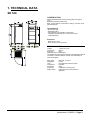
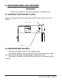
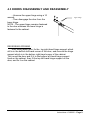
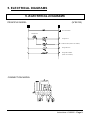
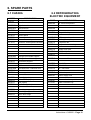
9
REFRIGERATED CABINETS
BIOCOLD
SR 530
TECHNICAL MANUAL
INCLUDING
- USER MANUAL
- INSTRUCTIONS
BONNET GRANDE CUISINE
Rue des Frères Lumière - Z.I. Mitry Compans
77292 MITRY MORY cedex
Tél. 01 60 93 70 00 - Fax. 01 60 93 70 43
FORM050B1/1
n°648260 - 01/02
RECTO
USER MANUAL
REFRIGERATED CABINETS
BIOCOLD
SR 530
CONTENTS
Important recommandations
2
1.Presentation of the control panel
3
2.Use
4
3.Service
5
BONNET GRANDE CUISINE
Rue des Frères Lumière - Z.I. Mitry Compans
77292 MITRY MORY cedex
Tél. 01 60 93 70 00 - Fax. 01 60 93 70 43
User Manual n°648260 – Page 1
IMPORTANT RECOMMANDATIONS
∗ This cabinet is made to be used in restaurants or cattering
and not in an industrial way.
∗ Only a specialist can install this cabinet.
∗ Avoid installing the cabinet near a major source of heat or
in direct exposure to sunlight.
∗ Note that a too high outdoor temperature can diminish the
performance of the appliance.
∗ The condenser of the compressor group must be regularly
cleaned (every 3 or 6 months) by a refrigeration engineer.
∗ Do not modify the electrical connection made by the
installer and particularly the continuity of the earth circuit.
∗ The feeder which is delivered with the appliance is a
specific part, which can only be replaced by an original part.
∗ Make sure that the supply plug is always accessible.
∗ In case of problems with the electrical circuit, only the
installer or the constructor is allowed to intervene.
∗ Observe the rules of hygiene by regularly cleaning the:
.interior fittings
.door seal
.the interior liner
Do not use corrosive products or acid.
∗ Water spattering can cause damage.
Do not clean with a water jet in order to avoid spattering
on the appliance.
. Do not install the appliance in the open air or in the rain.
THE SPECIFICATIONS AND CHARACTERISTICS IN THIS NOTICE
MAY BE MODIFIED WITHOUT PRIOR NOTICE.
User Manual n°648260 – Page 2
1. PRESENTATION OF THE CONTROL PANEL
1.1 WARNING
The thermostat does not cut off the main power of the appliance.
If the appliance is not used during a long time, power must be cut off with
the on/off switch, the plug or the disconnector because of the risk of dammaging
the refrigerating equipment.
1.2 CONTROL PANEL
Thermostat
Telethermometer
On/Off switch
Telethermometer which indicates the temperature inside the cabinet.
Thermostat graduated from 0 to 7. The lower temperature is obtained at the
position 7. This thermostat is equipped with a probe whose location is
imperative. In the case of a replacement, take care to carefully respect this
location.
User Manual n°648260 – Page 3
2. USE
2.1 GENERAL REQUIREMENTS
When operating for the first time or after prolonged period out of use, the
appliance should be run empty.
Loading may start only once the temperature set by the thermostat has
been reached.
Do not store food products in any way likely to hinder the ventilation
system which ensures the correct distribution and circulation of cold air inside
the appliance.
2.2 LOADING
A space of at least 15 mm is required between the each item to allow
refrigerated air to pass around the products.
2.3 VENTILATION
The ventilation system is deliberately powered at all times ; this ensures
operation when the doors are open and means that during heavy duty or loads
the front of the evaporator does not ice up.
2.4 DEFROST
Whatever the position of the thermostat, defrost is ensured after each stop.
If defrost seems to be excessive, bring back periodically the thermostat switch
to the inferior position or position on 0.
2.5 DEFROST WATER COLLECTION
Under each appliance is a tray to collect the defrost water and has to be
emptied. The rate at which it has to be emptied depends above all on the rate of
service and the outdoor temperature conditions in which the cabinet is
operating. In principle the tray should be emptied a maximum of once per day.
User Manual n°648260 – Page 4
3. SERVICE
WARNING
Before any cleaning of electrical components,
ensure the appliance is switched OFF.
Do not clean with a water jet
in order to avoid spattering on the appliance.
3.1 INTERIOR LINING
It is necessary to eliminate stains once per day.
To ease the complete cleaning of the interior lining, the internal fitting can
be easily disassembled (shelf slide and slides support).
3.2 STAINLESS STEEL SURFACE
Use warm water and soap or a non-corrosive neutral detergent (such as
Teepol or an equivalent product). Carefully rince and dry the appliance
Never use Javell water, even when highly diluted.
Never rub stainless steel with metal wool; if necessary, use only Scotch
Brite or an equivalent product. Fingerprints can be easily removed by rubbing
with a cloth soaked in alcohol.
3.3 PERIODICAL CLEANING.
In order to maintain the refrigerating capacity and to ensure the longevity of
the compressor, it is necessary to clean regularly (every 3 or 6 months) the
condenser unit. This operation must be carried out by the installer.
User Manual n°648260 – Page 5
INSTRUCTIONS
REFRIGERATED CABINETS
BIOCOLD
SR 530
CONTENTS
Important recommendations
2
1.Technical data
3
2.Installation
4
3.Operation
6
4.Intervention and repair
7
5.Electrical diagrams
8
6.Spare parts
9
BONNET GRANDE CUISINE
Rue des Frères Lumière - Z.I. Mitry Compans
77292 MITRY MORY cedex
Tél. 01 60 93 70 00 - Fax. 01 60 93 70 43
Instruction n°648260 – Page 1
IMPORTANT RECOMMANDATIONS
∗ When installing the cabinet, ensure that air circulation and
volume is adequate to enable normal cooling of the
condenser and compressor.
∗ Avoid installing the cabinet near a major source of heat, or
in direct exposure to sunlight.
∗Note that a too high outdoor temperature can diminish the
performance of the appliance.
∗ Continuity of the earth circuit must be maintained between
the appliance and its power point.
∗ The feeder which is delivered with the appliance is a
specific part, which can only be replaced by an original part.
∗ Make sure that the supply plug is always accessible.
∗ The installer is responsible for protecting the appliance
against overloads or electrical defects. Ensure a circuitbreaker or fuses are installed (see description).
∗ Any operation on the electric or refrigerating circuits and all
cleaning operations are to be performed only when the
appliance has been switched OFF.
∗ The condenser must be regularly cleaned (every 3 or 6
months).
∗ Water spattering can cause damage.
Do not clean with a water jet in order to avoid spattering
on the appliance.
. Do not install the appliance in the open air or in the rain.
∗ By any operations, respect absolutely initial fitting rules to
ensure the security of the appliance.
THE SPECIFICATIONS AND CHARACTERISTICS IN THIS NOTICE MAY BE
MODIFIED WITHOUT PRIOR NOTICE.
Instructions n°648260 – Page 2
1. TECHNICAL DATA
SR 530
CONSTRUCTION
White plasticized sheet exterior casing (sides, front panel,
door).
Stainless austenitic interior lining.
Back, top and bottom of the exterior casing in corrosion proof
galvanized sheet.
Insulated body
- Monocoque type.
- Radiused interior
- Polyurethane foam insulation, 45mm thick.
- Thermal break between inner and outer structure.
- 4 adjustable legs.
- Cordon chauffant anti-condensation. (modèle négatif)
Plain door
- Magnetic door seal.
- Door opening can be reversed.(1 porte)
TECHNICAL DATA
Voltage
: 1~230V 50 Cycle
Input power
: 250 W
Protection
: aM 4
Delivered with a moulded plug.
The installer is responsible for protecting the appliance against
overloads or electrical defects. Ensure a circuit-breaker or
fuses are installed.
Refr. power
Refrigerant
Load
Compressor
Condenser
Evaporator
Defrost water
: 200 W at -10/+55°C
: R134a
: See appliance instruction plate.
: Hermetic
: Static
: Ventilated, corrosion proof
: Collection tray located under the
appliance.
Instructions n°648260 – Page 3
2. INSTALLATION
2.1 GENERAL REQUIREMENTS
All installation, modification or repair work on the appliance must be carried out
by a specialised installer according to industrial standards.
2.2 HANDLING
The appliance must be handled with suitable hoisting equipment.
If the appliance is to be transported, use its original pallet and never lay it over
other appliances.
When moving the appliance without its pallet, it must be carried and not pulled
out.
2.3 UNPACKING AND INSTALLATION
2.3.1 LOCATION
When choosing the location, make sure that there is sufficient air circulation
around the appliance to allow correct cooling of the condenser and compressor.
Do not install near a source of heat.
2.3.2 UNPACKING
Follow the instructions supplied with the unit.
Instructions n°648260 – Page 4
2.3.3 DEFROST WATER COLLECTION TRAY ASSEMBLY
First screw the 4 H-M6 screws
then put the slides into place in the
slots. Tighten again completely the 4
screws.
Then install the defrost water
collection tray.
H-M6 screw
Slides
Tiroir à eaux
Water collection tray
2.3.4 CONNECTIONS
See paragraph 1. ‘Technical data’.
ELECTRICAL
The appliance is fitted with a power plug which must not be disconnected.
Continuity of earth circuit must be ensured (see important recommendations).
The user is responsible for installing a circuit-breaker or fuses.
DEFROST WATER
The defrost water collection tray can be replaced by a drain trap (20 mm
connection).
Instructions n°648260 – Page 5
3. OPERATION
3.1 GENERAL REQUIREMENTS
Ensure that nothing blocks up the evaporator and condenser fans.
If the cabinet may have been laid on its side during transport or installation,
wait 24 hours before starting operation in order for the oil to flow back from the
refrigeration circuit to the compressor crankcase.
For appliance with grates, put the shelf slides onto the slides support.
3.2 CONTROL PANEL
See user manual.
Instructions n°648260 – Page 6
4. INTERVENTIONS AND REPAIRS
WARNING
Before any operations, ensure the appliance is switched OFF.
4.1 ACCESS TO ELECTRIC PLATE
Remove the electric plate unscrewing the H-M6 screws which fix it on the
ceiling.
Electric board
H-M6 screw
4.2 EVAPORATOR ACCESS
Take out the rubber elbow from the ABS housing.
For freezing cabinets, take out the flow heater to avoid hazards. Make
sure to put it correctly while reassemblying it into the flow tube.
According to cabinets, use a screwdriver (flat tool) or unscrew the ABS
housing.
Instructions n°648260 – Page 7
4.3 DOORS DISASSEMBLY AND REASSEMBLY
- Unscrew the upper hinge using a 10
wrench.
- Then disengage the door from the
lower hinge.
NOTA : The upper hinge remains fastened
to the door whereas the lower hinge is
fastened to the cabinet.
Upper hinge
REVERSING OPENING :
After taking apart door, fix the top right-hand hinge support which
still is in the bottom left-hand corner of the door, and remove the hinge
support which is in the bottom right-hand corner of the cabinet.
Turn round the door and fit it to the bottom left-hand hinge support
fixed on the cabinet, then fit the top left-hand hinge support on the
door, and fix it on the cabinet.
Instructions n°648260 – Page 8
5. ELECTRICAL DIAGRAMS
5. ELECTRICAL DIAGRAMS
PRINCIPLE MODEL
(N°SE122)
On / Off switch
Thermostat
Compressor
Condenser fan (relative to models)
Evaporator fan
Evaporation heater
(relative to models)
CONNECTION MODEL
Thermostat
Instructions n°648260 – Page 9
6. SPARE PARTS
6.1 CASING
CODE
S70P02
6.2 REFRIGERATING
ELECTRIC EQUIPMENT
DESIGNATION
Black plastic stand
S480PM51 Right facia side
S480PN51 Left facia side
Facia bracket
S481P51
S174P51
S170P51
S175P51
S171P51
S478PM51
S478PN51
S479P51
S032P03
S043PA58
S306P11
S136P11
CODE
S090P40
DESIGNATION
GL 50 AB compressor
S050P30
Wire condenser
S021P20
10 grs. XH 6 dryer
S550PM53
S978P70
S158P15
S058P11
MF2 evaporation unit
S046P12
S048P12
S109P11
Rubber flow tube
S086P42
Pressure relief valve
S049P20
S054P20
S210P15
0/+12°C thermostat
Control panel
Control panel with recorder
Electronic control panel
Electronic control panel+recorder
10/10 Ig.3m capillary
Evaporator fan
Evaporation unit casing
PVC flexible flow bend
PVC fixed flow bend
Left/right front slides support
Left/right front slides support
Back slides support
Support axis screw
Insulated white / stainless door
-35/+60°C thermometer
On / Off switch
Door label
Door magnetic seal
S486P51
S352P51
S053P01
S057P01
Door clip (option)
S009P01
S018P02
S085P01
Door hinge support (bottom/right)
Lock stiffener (option)
lock (option)
S058P15
S845P51
Cable clamp
S154P47
S177P51
Water collection tray slides
Power supply cord
Water collection tray
Catch bolt (option)
Door hinge support axis
Delrin door hinge
Instructions n°648260 – Page 10
DECLARATION DE CONFORMITE
CONFORMITY DECLARATION
HERSTELLERKONFORMITÄTSERKLÄRUNG
TYPE / TYPE / TYP
N° DE SERIE / SERIAL N° / FAB Nr
:
:
Cet appareil est conforme aux dispositions de la directive « Basse tension » 73/23/CEE et de
la directive « Compatibilité électromagnétique » 89/336/CEE.
This appliance complies with the provisions of the low voltage directive EEC/73/23 and with the provisions of the
electromagnetic compatibility directive EEC/89/336.
Dieses Gerät entspricht nach den Bestimungen der niederspannung-richtlinie EWG/73/23 und den
Bestimmungen der elektromagnetischen Übereinstimmung-richtlinie EWG/89/336.
Il est également conforme aux dispositions de normes européennes harmonisées
suivantes :
It is in compliance with the following harmonized standards :
Und entspricht ebenfalls der folgenden Europaïschen Norme :
- EN 60335 - 1
Sécurité des appareils électrodomestiques et analogues
Safety of houseold and similar electrical appliances
Elektrische Geräte für den Hausfebrauch und ähnliche Zwecke
DIRECTION GENERALE
Général Manager
Betriebsleiter
FORM055A1/1
Siège Social : BONNET GRANDE CUISINE. Rue de Frères Lumière , Z.I. de MITRY COMPANS , 77292 MITRY MORY CEDEX
Tél. : 01 60 93 70 00
Fax : 01 60 93 70 43
S.A.S au capital de 1 600 000 Euros.
RCS MEAUX B 319 053 005