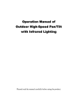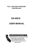
1
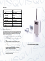
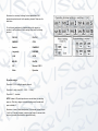
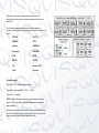
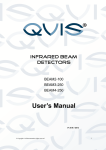
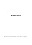
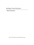
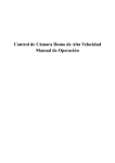
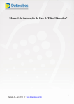
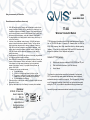
Qvis gives a warranty of 24 months QVIS www.adata.co.uk General terms and conditions of a warranty 1. 2. 3. 4. 5. 6. 7. 8. QVIS LABS warrants that the Product(s) shall be of satisfactory quality within the meaning of the Sale of Goods Act 1979; be reasonably fit for purpose, and; free from defects in materials or workmanship. The period of such warranties shall be as set in the price list that is current at the date of despatch of the Product(s) and the warranty period shall commence on the date of despatch of the Product(s). Any alleged defects in the Product(s) must be notified in writing within 14 days of receipt of the Product(s). In the event of any established breach of warranty, QVIS LABS shall repair or replace in its absolute discretion any defective Product(s). The Buyer shall be liable for the delivery charges incurred in returning the defective Product(s) to QVIS LABS, but shall not be liable for the cost of repair or replacement, or the delivery charge for returning the repaired or replaced Product(s) to the Buyer. If QVIS LABS complies with this clause then it shall have no further liability for breach of the warranty. Repairs undertaken by QVIS LABS under the terms of its warranty are guaranteed for 90 days from the date of dispatch to the Buyer. Where QVIS LABS in its absolute discretion replaces any defective Product(s), the warranty on such replacement Product(s) shall continue in effect for the remainder of the unexpired term of the warranty commencing from the original date of despatch of the defective Product(s). Any replaced Product(s) become the property of QVIS LABS. The warranty shall not cover any defect caused: a) By fair wear and tear. b) In whole or in part by the negligence of the Buyer or a User. c) By improper or unauthorised use of the Product(s) including any attempt to carry out repairs or modifications to the Product(s). d) By causes external to the Product(s). Failure by the Buyer to settle accounts rendered for Product(s) supplied will render the warranty null & void. If the Buyer adds labels to any of the Product(s) the warranty will be invalidated. Distributer: QVIS HQ, 36 New Lane, Havant, Hampshire, PO9 2JL Offers and information: www.adata.co.uk Customer services: [email protected] TT-202 Wireless Telemetric Modem TT-202 is designed f or wireless control of high speed cameras ov er the radiolink on ISM 869 MHz band. It supports 10 channels within the 869.4 to 869.65 MHz f requency band. Each channel has a f actory def ined operating f requency . It has both the bi-directional RS485 and RS232 interf aces and designed f or operation in Point- Multipoint conf iguration. Contents of TT-202 package: Bi-directional telemetric module with RS485, RS232 and TTL port Stub omnidirectional antenna ( up to 6km distance) User’s Manual This telemetric sy stem has been created f or the demands of prof essional CCTV sy stems with high speed cameras and recorders, where stable and unattended control ov er radio-links is required. There is a possibility of using up to 10 independent operating channels with v ery high transmission quality making the TT-202 v ery suitable f or almost all monitoring high demand sy stems with high speed cameras and industrial automatic control sy stems . Qvis gives a warranty of 24 months QVIS www.adata.co.uk General terms and conditions of a warranty 1. 2. 3. 4. 5. 6. 7. 8. QVIS LABS warrants that the Product(s) shall be of satisfactory quality within the meaning of the Sale of Goods Act 1979; be reasonably fit for purpose, and; free from defects in materials or workmanship. The period of such warranties shall be as set in the price list that is current at the date of despatch of the Product(s) and the warranty period shall commence on the date of despatch of the Product(s). Any alleged defects in the Product(s) must be notified in writing within 14 days of receipt of the Product(s). In the event of any established breach of warranty, QVIS LABS shall repair or replace in its absolute discretion any defective Product(s). The Buyer shall be liable for the delivery charges incurred in returning the defective Product(s) to QVIS LABS, but shall not be liable for the cost of repair or replacement, or the delivery charge for returning the repaired or replaced Product(s) to the Buyer. If QVIS LABS complies with this clause then it shall have no further liability for breach of the warranty. Repairs undertaken by QVIS LABS under the terms of its warranty are guaranteed for 90 days from the date of dispatch to the Buyer. Where QVIS LABS in its absolute discretion replaces any defective Product(s), the warranty on such replacement Product(s) shall continue in effect for the remainder of the unexpired term of the warranty commencing from the original date of despatch of the defective Product(s). Any replaced Product(s) become the property of QVIS LABS. The warranty shall not cover any defect caused: a) By fair wear and tear. b) In whole or in part by the negligence of the Buyer or a User. c) By improper or unauthorised use of the Product(s) including any attempt to carry out repairs or modifications to the Product(s). d) By causes external to the Product(s). Failure by the Buyer to settle accounts rendered for Product(s) supplied will render the warranty null & void. If the Buyer adds labels to any of the Product(s) the warranty will be invalidated. Distributer: QVIS HQ, 36 New Lane, Havant, Hampshire, PO9 2JL Offers and information: www.adata.co.uk Customer services: [email protected] TT-202 Wireless Telemetric Modem TT-202 is designed f or wireless control of high speed cameras ov er the radiolink on ISM 869 MHz band. It supports 10 channels within the 869.4 to 869.65 MHz f requency band. Each channel has a f actory def ined operating f requency . It has both the bi-directional RS485 and RS232 interf aces and designed f or operation in Point- Multipoint conf iguration. Contents of TT-202 package: Bi-directional telemetric module with RS485, RS232 and TTL port Stub omnidirectional antenna ( up to 6km distance) User’s Manual This telemetric sy stem has been created f or the demands of prof essional CCTV sy stems with high speed cameras and recorders, where stable and unattended control ov er radio-links is required. There is a possibility of using up to 10 independent operating channels with v ery high transmission quality making the TT-202 v ery suitable f or almost all monitoring high demand sy stems with high speed cameras and industrial automatic control sy stems . Specification: Modulation RC2FSK Power <200mW / <500mW Input-Output RS485 , RS232, TTL 5V Antenna Input SMA M/ 50 Transmission Half -Duplex Baudrate 1200 to 9600 bps Power supply 10-12V / 500mA DC Operating Temperature -20 °C + 50 °C Dimensions 125x105x60 mm Weight 0,4 kg Preparing modules f or operation: It is recommended to perform the first start-up and configuration setup within workshop conditions over short distances b etween devices. This can save the valuable time in the configuration of TT-202 for various cameras used in video monitoring. Fix and direct the antenna in such a way to achiev e clearest ‘line of sight’ between the two. Connect the RS485 wires appropriately to the modules’ terminals (A, B) Connect the sources of signal (control key board – camera). Connect the power adaptor to the telemetric modules, then to the wall outlet. The LED indicator on panel will indicate that the data is being transmitted. When the sy stem is conf igured correctly , LEDs on both modules should light simultaneously in red signaling a connection to take control of the camera(s). Check the if ev ery thing works correctly and quality of the camera control. Upon completion of setup changes, reset the dev ice by disconnecting the power supply . TT-202 Wireless Telemetric Modem Specification: Modulation RC2FSK Power <200mW / <500mW Input-Output RS485 , RS232, TTL 5V Antenna Input SMA M/ 50 Transmission Half -Duplex Baudrate 1200 to 9600 bps Power supply 10-12V / 500mA DC Operating Temperature -20 °C + 50 °C Dimensions 125x105x60 mm Weight 0,4 kg Preparing modules f or operation: It is recommended to perform the first start-up and configuration setup within workshop conditions over short distances b etween devices. This can save the valuable time in the configuration of TT-202 for various cameras used in video monitoring. Fix and direct the antenna in such a way to achiev e clearest ‘line of sight’ between the two. Connect the RS485 wires appropriately to the modules’ terminals (A, B) Connect the sources of signal (control key board – camera). Connect the power adaptor to the telemetric modules, then to the wall outlet. The LED indicator on panel will indicate that the data is being transmitted. When the sy stem is conf igured correctly , LEDs on both modules should light simultaneously in red signaling a connection to take control of the camera(s). Check the if ev ery thing works correctly and quality of the camera control. Upon completion of setup changes, reset the dev ice by disconnecting the power supply . TT-202 Wireless Telemetric Modem Sometimes it is necessary to change the basic parameters of the transmission protocol as well as the operating channels. Please use the table below. To set the basic parameters of telemetric protocols (of cameras, or recorders), use Dip switches. It works, among others, with the f ollowing protocols: - PELCO-D - PELCO-P , - SAMSUNG - COP-2 - Santachi - PANASONIC - Longcomity - HUNDA600 - LILIN - VICON - MOLYNX - KALATEL - VCL - Reserved COP-1 - Ultrak - Dynacolor Dip switch settings: Dip switch: 2,3,4,5 – setting of operating channel Dip switch: 8 - parity check (8E1 - 0, 8N1 - 1 – Pelco ) Dip switch: 6, 7 – baudrate NOTE: Readout of Dip switch positions are executed when the switching power on. That`s why changes to the switch settings are to be made with power switched of f . Sometimes, in case of bidirectional protocol, it is necessary to short the pins 1 and 2 on J3 terminal strip using “computer-ty pe” jumper. An access to this strip is only possible af ter remov al of upper metal casing. Sometimes it is necessary to change the basic parameters of the transmission protocol as well as the operating channels. Please use the table below. To set the basic parameters of telemetric protocols (of cameras, or recorders), use Dip switches. It works, among others, with the f ollowing protocols: PELCO-D PELCO-P , - SAMSUNG - COP-2 - Santachi - PANASONIC - Longcomity - HUNDA600 - LILIN - VICON - MOLYNX - KALATEL - VCL - Reserved COP-1 - Ultrak - Dynacolor Dip switch settings: Dip switch: 2,3,4,5 – setting of operating channel Dip switch: 8 - parity check (8E1 - 0, 8N1 - 1 – Pelco ) Dip switch: 6, 7 – baudrate NOTE: Readout of Dip switch positions are executed when the switching power on. That`s why changes to the switch settings are to be made with power switched of f . Sometimes, in case of bidirectional protocol, it is necessary to short the pins 1 and 2 on J3 terminal strip using “computer-ty pe” jumper. An access to this strip is only possible af ter remov al of upper metal casing. For more inf ormation about our wireless transmission kits and all other av ailable products, please v isit our website: www.adata.co.uk Alternativ ely scan this QR code with y our smart phone to be directed instantly to our website: For more inf ormation about our wireless transmission kits and all other av ailable products, please v isit our website: www.adata.co.uk Alternativ ely scan this QR code with y our smart phone to be directed instantly to our website: