1
53-1003255-03
22 May 2015
Brocade NetIron
Security Configuration Guide
Supporting Multi-Service IronWare R05.8.00b
© 2015, Brocade Communications Systems, Inc. All Rights Reserved.
ADX, Brocade, Brocade Assurance, the B-wing symbol, DCX, Fabric OS, HyperEdge, ICX, MLX, MyBrocade, OpenScript, The Effortless
Network, VCS, VDX, Vplane, and Vyatta are registered trademarks, and Fabric Vision and vADX are trademarks of Brocade
Communications Systems, Inc., in the United States and/or in other countries. Other brands, products, or service names mentioned may be
trademarks of others.
Notice: This document is for informational purposes only and does not set forth any warranty, expressed or implied, concerning any
equipment, equipment feature, or service offered or to be offered by Brocade. Brocade reserves the right to make changes to this document
at any time, without notice, and assumes no responsibility for its use. This informational document describes features that may not be
currently available. Contact a Brocade sales office for information on feature and product availability. Export of technical data contained in
this document may require an export license from the United States government.
The authors and Brocade Communications Systems, Inc. assume no liability or responsibility to any person or entity with respect to the
accuracy of this document or any loss, cost, liability, or damages arising from the information contained herein or the computer programs that
accompany it.
The product described by this document may contain open source software covered by the GNU General Public License or other open
source license agreements. To find out which open source software is included in Brocade products, view the licensing terms applicable to
the open source software, and obtain a copy of the programming source code, please visit http://www.brocade.com/support/oscd.
Contents
Preface...................................................................................................................................15
Document conventions....................................................................................15
Text formatting conventions................................................................ 15
Command syntax conventions............................................................ 15
Notes, cautions, and warnings............................................................ 16
Brocade resources.......................................................................................... 17
Contacting Brocade Technical Support...........................................................17
Document feedback........................................................................................ 18
About This Document.............................................................................................................. 19
Supported hardware and software.................................................................. 19
Supported software............................................................................. 19
Notice to the reader.........................................................................................20
How command information is presented in this guide.....................................20
Securing Access to Management Functions............................................................................. 21
Securing access methods............................................................................... 23
Restricting remote access to management functions..................................... 26
Using ACLs to restrict remote access ................................................ 27
Defining the console idle time............................................................. 29
Restricting remote access to the device to specific IP addresses...... 30
Defining the Telnet idle time................................................................31
Specifying the maximum login attempts for Telnet access ................ 32
Restricting remote access to the device to specific VLAN IDs............32
Enabling specific access methods...................................................... 33
Setting passwords...........................................................................................35
Setting a Telnet password ..................................................................36
Setting passwords for management privilege levels........................... 36
Recovering from a lost password........................................................39
Displaying the SNMP community string.............................................. 39
Disabling password encryption........................................................... 39
Specifying a minimum password length..............................................40
Setting up local user accounts........................................................................ 40
Configuring a local user account.........................................................41
Enabling strict password enforcement............................................................ 42
Configuring the strict password rules.................................................. 42
Password history.................................................................................43
Setting passwords to expire................................................................ 43
Login lockout....................................................................................... 44
Requirement to accept the message of the day..................................44
Regular password rules...................................................................... 44
Strict password rules...........................................................................45
Web interface login lockout............................................................................. 45
Creating an encrypted all-numeric password..................................................46
Granting access by time of day.......................................................................46
Configuring SSL security for the Web Management Interface........................ 46
Enabling the SSL server on a Brocade device....................................47
Importing digital certificates and RSA private key files....................... 47
Brocade NetIron Security Configuration Guide
53-1003255-03
3
Generating an SSL certificate........................................................... 48
Configuring TACACS or TACACS+ security.................................................48
How TACACS+ differs from TACACS...............................................48
TACACS or TACACS+ authentication, authorization, and
accounting................................................................................... 49
TACACS or TACACS+ configuration considerations........................52
Enabling SNMP traps for TACACS................................................... 53
Identifying the TACACS or TACACS+ servers................................. 53
Specifying different servers for individual AAA TACACS
functions...................................................................................... 54
Brocade NetIron XMR Series and Brocade NetIron MLX
SeriesSetting optional TACACS or TACACS+ parameters.........55
Configuring authentication-method lists for TACACS or
TACACS+....................................................................................56
Configuring TACACS+ authorization................................................ 59
Configuring TACACS+ accounting....................................................62
Configuring an interface as the source for all TACACS or
TACACS+ packets...................................................................... 63
Displaying TACACS or TACACS+ statistics and configuration
information...................................................................................63
Validating TACACS+ reply packets.................................................. 65
Configuring RADIUS security........................................................................68
RADIUS authentication, authorization, and accounting.................... 68
RADIUS configuration considerations...............................................72
RADIUS configuration procedure......................................................73
Configuring Brocade-specific attributes on the RADIUS server........73
Enabling SNMP traps for RADIUS ................................................... 75
Identifying the RADIUS server to the Brocade device...................... 76
Specifying different servers for individual AAA functions.................. 76
Radius health check..........................................................................77
Setting RADIUS parameters............................................................. 78
Configuring authentication-method lists for RADIUS........................ 79
Configuring RADIUS authorization....................................................80
Configuring RADIUS accounting.......................................................82
Configuring an interface as the source for all RADIUS packets....... 83
Configuring an IPv6 interface as the source for all RADIUS
packets........................................................................................ 84
Displaying RADIUS configuration information...................................84
Configuring AAA on the console................................................................... 85
Configuring AAA authentication-method lists for login.................................. 86
Configuring authentication-method lists........................................................87
Configuration considerations for authentication-method lists........... 88
Examples of authentication-method lists...........................................88
Layer 2 Access Control Lists.................................................................................................. 91
Configuration rules and notes....................................................................... 92
General considerations..................................................................... 92
Configuration considerations for dual inbound ACLS on
Brocade NetIron CES Series and Brocade NetIron CER
Series devices............................................................................. 93
Configuration considerations for VPLS, VLL, and VLL-Local
endpoints ....................................................................................93
Types of Layer-2 ACLs..................................................................... 93
ACL editing and sequence numbers................................................. 94
Creating a numbered Layer-2 ACL table...................................................... 95
Re-sequencing a numbered Layer-2 ACL table................................96
Filtering and priority manipulation based on 802.1p priority............. 98
4
Brocade NetIron Security Configuration Guide
53-1003255-03
Inserting and deleting Layer-2 ACL clauses....................................... 99
Increasing the maximum number of clauses per Layer-2 ACL
table...............................................................................................99
Binding a numbered Layer-2 ACL table to an interface.................... 100
Filtering by MAC address .................................................................100
Filtering broadcast traffic...................................................................100
Using the priority option ................................................................... 100
Using the priority force option........................................................... 101
Using the priority mapping option......................................................101
Using the drop-precedence keyword option......................................101
Using the drop-precedence-force keyword option............................ 101
Using the mirror keyword option....................................................... 102
Using the mark flow ID keyword option.............................................102
Creating a named Layer-2 ACL table............................................................102
Binding a named Layer-2 ACL table to an interface......................... 103
ACL accounting.............................................................................................103
Enabling and disabling ACL accounting on Brocade NetIron XMR
Series and Brocade NetIron MLX Series devices....................... 103
ACL accounting on Brocade NetIron CES Series and Brocade
NetIron CER Series devices........................................................104
Displaying Layer-2 ACLs...............................................................................105
Displaying Layer-2 ACL statistics on Brocade NetIron XMR
Series and Brocade NetIron MLX Series devices....................... 106
Configuring ACL Deny Logging for Layer-2 inbound ACLs...............107
Displaying Layer-2 ACL statistics on Brocade NetIron CES
Series and Brocade NetIron CER Series devices....................... 108
Access Control List................................................................................................................109
How the Brocade device processes ACLs.................................................... 111
General configuration guidelines.......................................................112
Configuration considerations for dual inbound ACLs on Brocade
NetIron CES Series and Brocade NetIron CER Series devices.. 112
Configuration considerations for IPv4 outbound ACLs on VPLS,
VLL, and VLL-Local endpoints ................................................... 113
Disabling outbound ACLs for switching traffic...............................................113
CAM considerations for Brocade NetIron CES Series and
Brocade NetIron CER Series devices......................................... 114
Globally enabling outbound ACLS for switching traffic .................... 114
Enabling outbound ACLS for switching traffic per port......................114
Default ACL action........................................................................................ 115
Types of IP ACLs.......................................................................................... 115
CES and CER Internal ACL.......................................................................... 115
ACL IDs and entries...................................................................................... 117
Enabling support for additional ACL statements .............................. 117
ACL editing and sequence numbers................................................. 118
Configuring numbered and named ACLs......................................................119
Configuring standard numbered ACLs..............................................119
Configuring extended numbered ACLs............................................. 122
Configuring standard or extended named ACLs .............................. 130
Displaying ACL definitions................................................................ 133
Adding 1000 Layer-2 numbered ACL................................................134
VLAN Accounting.............................................................................. 134
Simultaneous per VLAN rate limit and QoS.................................................. 134
Modifying ACLs............................................................................................. 135
Adding or deleting a comment ......................................................... 137
Applying ACLs to interfaces.......................................................................... 139
Reapplying modified ACLs................................................................139
Brocade NetIron Security Configuration Guide
53-1003255-03
5
Applying ACLs to a virtual routing interface.................................... 139
Deletion of ACLs bound to an interface.......................................... 140
Enabling ACL duplication check ................................................................ 141
Enabling ACL conflict check .......................................................................142
Enabling ACL filtering of fragmented or non-fragmented packets ............. 142
Numbered ACLs..............................................................................142
Named ACLs...................................................................................143
Configuring the conservative ACL fragment mode......................... 143
ACL filtering for traffic switched within a virtual routing interface ............... 148
Filtering and priority manipulation based on 802.1p priority....................... 149
Example using the priority option (IPv4)......................................... 149
Example using the priority force option .......................................... 150
Example using the priority mapping option .................................... 150
ICMP filtering for extended ACLs ...............................................................150
Numbered ACLs..............................................................................150
Named ACLs...................................................................................151
Binding IPv4 inbound ACLs to a management port.................................... 153
IP broadcast ACL........................................................................................154
Configuration considerations for IP broadcast ACL........................ 155
Configuring IP broadcast ACL and establishing the sequence of
IP broadcast ACL commands....................................................155
Configuration example for IP broadcast ACL..................................156
Displaying accounting information for IP broadcast ACL................ 156
Clearing accounting information for IP broadcast ACL................... 158
IP broadcast ACL CAM............................................................................... 158
Considerations for implementing IP broadcast ACL....................... 159
Specifying the maximum CAM size for IP broadcast ACL ............. 159
Rebinding of IP broadcast ACL CAM entries.................................. 160
IP receive ACLs ......................................................................................... 160
Configuration guidelines for IP receive ACLs................................. 161
Configuring rACLs...........................................................................161
Displaying accounting information for rACL ................................... 165
ACL CAM sharing for inbound ACLs for IPv4 ACLs(Brocade NetIron
XMR Series and Brocade MLXe Series devices only).......................... 165
Considerations when implementing this feature............................. 166
Configuring ACL CAM sharing for IPv4 ACLs.................................166
Matching on TCP header flags for IPv4 ACLs............................................ 166
ACL deny logging........................................................................................167
Configuration notes......................................................................... 167
Configuring ACL deny logging for IPv4 ACLs................................. 169
Configuring ACL Deny Logging for IP receive ACLs...................... 170
Configuring the log timer................................................................. 170
Support for ACL CAM sharing.........................................................170
Log example....................................................................................170
ACL accounting...........................................................................................171
Enabling and disabling ACL accounting on Brocade NetIron
XMR Series and Brocade MLXe Series devices....................... 171
ACL accounting on Brocade NetIron CES Series and Brocade
NetIron CER Series devices......................................................171
Displaying accounting statistics for all ACLs...................................173
Configuring an IPv6 Access Control List...............................................................................177
Configuration considerations for dual inbound ACLS on Brocade
NetIron CES Series and Brocade NetIron CER Series devices............ 179
Configuration considerations for IPv6 ACL and multicast traffic for
2X100GE modules installed on NetIron MLX and NetIron XMR
devices.................................................................................................. 180
6
Brocade NetIron Security Configuration Guide
53-1003255-03
Configuration considerations for IPv6 outbound ACLs on VPLS, VLL,
and VLL-local endpoints ......................................................................... 180
ACL editing and sequence numbers............................................................. 181
Upgrade and downgrade considerations.......................................... 181
Using IPv6 ACLs as input to other features.................................................. 183
Configuring an IPv6 ACL...............................................................................183
Example configurations.....................................................................183
Default and implicit IPv6 ACL action................................................. 185
Re-sequencing an IPv6 ACL table.................................................... 186
Deleting an IPv6 ACL entry...............................................................186
ACL syntax........................................................................................187
Filtering packets based on DSCP values..........................................200
Marking the DSCP value in a packet................................................ 201
Filtering packets based on routing header type................................ 201
Extended IPv6 ACLs..................................................................................... 201
Configuration considerations for extended IPv6 layer 4 ACL............202
Unsupported features for Brocade NetIron CES Series and
Brocade NetIron CER Series devices......................................... 202
ACL syntax........................................................................................203
Configuration considerations for Layer 2 IPv6 ACLs........................ 208
ACL syntax........................................................................................209
Displaying IPv6 ACL definitions.................................................................... 209
CAM partitioning............................................................................................210
TCAM IFSR.......................................................................................210
Applying an IPv6 ACL................................................................................... 211
Reapplying modified IPv6 ACLs........................................................212
Applying an IPv6 ACL to a VRF Interface......................................... 212
Controlling access to a Brocade device............................................ 213
Adding a comment to an IPv6 ACL entry...................................................... 213
ACL CAM sharing for inbound IPv6 ACLs.................................................... 215
Considerations when implementing this feature............................... 216
Configuring ACL CAM sharing for IPv6 ACLs...................................216
Filtering and priority manipulation based on 802.1p priority..........................216
Example using the priority force option ............................................ 217
ACL accounting.............................................................................................217
Enabling and Disabling ACL accounting on Brocade NetIron
XMR Series and Brocade NetIron MLX Series devices.............. 217
ACL accounting on Brocade NetIron CES Series 2000 and
Brocade NetIron CER Series 2000 devices................................ 218
Enabling and disabling IPv6 ACL accounting on Brocade
NetIron CES Series 2000 and Brocade NetIron CER Series
2000 devices ............................................................................. 218
Displaying statistics for IPv6 ACL accounting................................... 219
IPv6 receive ACLs.........................................................................................221
IPv6 receive ACLs overview............................................................. 221
IPv6 receive ACLs configuration considerations...............................222
IPv6 receive ACL prerequisites.........................................................222
IPv6 receive ACL: basic configuration.............................................. 226
IPv6 receive ACL: additional configuration....................................... 228
Syslog messages for IPv6 rACLs......................................................229
Displaying accounting information for IPv6 rACLs............................ 230
Configuring Secure Shell and Secure Copy............................................................................ 231
SSH server version 2 support....................................................................... 233
Supported SSHv2 clients.................................................................. 233
Supported features............................................................................233
Configuring SSH server.................................................................... 234
Brocade NetIron Security Configuration Guide
53-1003255-03
7
Generating a host key pair.............................................................. 236
Enabling and disabling SSH server by generating and deleting
host keys................................................................................... 237
Configuring DSA or RSA public key authentication........................ 238
Configuring DSA public key authentication..................................... 240
Setting optional parameters............................................................ 242
Disabling 3-DES..............................................................................245
Displaying SSH server connection information............................... 246
Ending an SSH server connection.................................................. 247
Outbound SSHv2 client...................................................................247
Using an SSH2 client...................................................................... 249
Displaying SSH2 client information................................................. 250
Using Secure Copy..................................................................................... 250
Secure Copy feature for Brocade NetIron CES Series and
Brocade NetIron CER Series.....................................................251
Secure Copy Feature for Brocade NetIron XMR Series................. 252
Configuring Multi-Device Port Authentication...................................................................... 263
How multi-device port authentication works................................................264
RADIUS authentication................................................................... 264
Authentication-failure actions.......................................................... 264
Supported RADIUS attributes......................................................... 264
Dynamic VLAN and ACL assignments ...........................................265
Support for authenticating multiple MAC addresses on an
interface.....................................................................................265
Support for multi-device port authentication and 802.1x on the
same interface........................................................................... 265
Configuring multi-device port authentication............................................... 266
Enabling multi-device port authentication....................................... 266
Configuring an authentication method list for 802.1x...................... 266
Setting RADIUS parameters........................................................... 267
Specifying the format of the MAC addresses sent to the
RADIUS server.......................................................................... 267
Specifying the authentication-failure action.................................... 268
Defining MAC address filters...........................................................268
Configuring dynamic VLAN assignment..........................................269
Specifying the VLAN to which a port is moved after the
RADIUS-specified VLAN assignment expires........................... 270
Saving dynamic VLAN assignments to the running configuration
file.............................................................................................. 271
Clearing authenticated MAC addresses......................................... 271
Disabling aging for authenticated MAC addresses......................... 271
Specifying the aging time for blocked MAC addresses...................272
Displaying multi-device port authentication information.............................. 272
Displaying authenticated MAC address information....................... 273
Displaying multi-device port authentication configuration
information.................................................................................273
Displaying multi-device port authentication information for a
specific MAC address or port.................................................... 276
Displaying the authenticated MAC addresses................................ 276
Displaying the non-authenticated MAC addresses......................... 277
Media Access Control Security (MACsec) - IEEE 802.1ae..................................................... 279
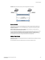
MACsec overview....................................................................................... 279
How MACsec works.................................................................................... 279
How MACsec handles data and control traffic................................ 280
8
Brocade NetIron Security Configuration Guide
53-1003255-03
MACsec Key Agreement protocol..................................................... 280
MKA message exchange between two switches.............................. 280
Secure channels............................................................................... 281
MACsec frame format....................................................................... 281
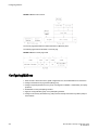
Configuring MACsec..................................................................................... 282
Enabling MACsec and configuring group parameters...................................283
Configuring MACsec integrity and encryption................................... 283
Configuring MACsec frame validation...............................................284
Configuring replay protection............................................................ 285
Enabling and configuring group interfaces for MACsec................................ 286
Configuring the pre-shared key.........................................................286
Sample MACsec configuration......................................................................287
Displaying MACsec information.................................................................... 288
Displaying MACsec configuration details.......................................... 288
Displaying information on current MACsec sessions........................ 289
Displaying MKA protocol statistics for an interface........................... 290
Displaying MACsec secure channel activity for an interface.............290
IPsec.................................................................................................................................... 293
IP security..................................................................................................... 293
IPsec overview.............................................................................................. 293
IPsec interoperability with Cisco................................................................... 296
Limitations of IPsec....................................................................................... 298
Configuring IPsec..........................................................................................299
Configuration example.................................................................................. 299
IPsec scaling limits........................................................................................303
Displaying IPsec and IKEv2 information....................................................... 304
Configuring IPsec error traps and syslogs.................................................... 308
Configuring IKEv2 error traps and syslogs....................................................308
IKEv2 traps....................................................................................................309
IPsec traps and syslogs................................................................................ 309
IPsec syslog messages.....................................................................310
PKI support for IPsec.................................................................................... 311
Certificates........................................................................................ 311
Entity................................................................................................. 311
Certificate Authority...........................................................................312
Registration authority........................................................................ 312
PKI repository....................................................................................312
Lightweight Directory Access Protocol..............................................312
Certificate revocation list................................................................... 312
CRL Distribution Point.......................................................................312
Distinguished Name.......................................................................... 312
Configuring PKI............................................................................................. 313
PKI configuration example............................................................................ 314
SCP client support................................................................................................................ 315
SCP client..................................................................................................... 315
SCP client support limitations....................................................................... 315
Supported SCP client configurations............................................................ 316
Uploading an image to an SCP server..........................................................317
Uploading configuration files to an SCP server.............................................317
Downloading configuration files from an SCP server....................................317
Using the MAC Port Security Feature..................................................................................... 319
Overview ..................................................................................................... 319
Brocade NetIron Security Configuration Guide
53-1003255-03
9
Configuration Considerations..........................................................320
Local and global resources......................................................................... 320
Configuring the MAC port security feature.................................................. 320
Enabling the MAC port security feature.......................................... 321
Setting the maximum number of secure MAC addresses for an
interface.....................................................................................321
Setting the port security age timer.................................................. 322
Specifying secure MAC addresses................................................. 322
Autosaving secure MAC addresses to the startup-config file......... 322
Setting to delete a dynamically learned MAC address on a
disabled interface...................................................................... 323
Specifying the action taken when a security violation occurs......... 323
Specifying the number of MAC addresses to be denied................. 324
Denying specific MAC addresses................................................... 324
Port security MAC violation limit......................................................325
Displaying port security information ........................................................... 326
Displaying port security settings......................................................326
Displaying the secure MAC addresses on the device.....................327
Displaying port security statistics.................................................... 327
Protecting against Denial of Service Attacks........................................................................329
Protecting against smurf attacks................................................................. 329
Avoiding being an intermediary in a smurf attack........................... 330
Avoiding being a victim in a smurf attack........................................ 330
Protecting against TCP SYN attacks.......................................................... 332
TCP security enhancement ............................................................332
Protecting against UDP attacks...................................................... 334
Enhanced DOS attack prevention for IPv6..................................... 334
Displaying statistics from a DoS attack....................................................... 335
Clear DoS attack statistics.......................................................................... 335
Securing SNMP Access....................................................................................................... 337
Establishing SNMP community strings....................................................... 338
Encryption of SNMP community strings..........................................338
Adding an SNMP community string................................................ 338
Displaying the SNMP community strings........................................ 339
Using the User-Based Security model........................................................ 339
Configuring your NMS.....................................................................340
Configuring SNMP version 3 on the device.................................... 340
Defining the engine ID.....................................................................340
Defining an SNMP group................................................................ 341
Defining an SNMP user account..................................................... 342
Displaying the engine ID................................................................. 343
Displaying SNMP groups................................................................ 344
Displaying user information.............................................................344
Interpreting varbinds in report packets............................................344
Defining SNMP views..................................................................................345
SNMP v3 configuration examples............................................................... 346
Simple SNMP v3 configuration....................................................... 346
More detailed SNMP v3 configuration.............................................346
ACL Editing and Sequence Numbers....................................................................................347
Background.................................................................................................347
Layer-2 and IPv4 ACLs .................................................................. 347
IPv6 ACLs ...................................................................................... 348
10
Brocade NetIron Security Configuration Guide
53-1003255-03
Sequence Numbers...................................................................................... 348
Internal and User Specified ..............................................................348
Displaying ACL entry sequence numbers......................................... 349
Creating an ACL filter....................................................................................349
Re-generating ACL sequence numbers........................................................350
Deleting ACL entries using the entry sequence number...............................350
Backward compatibility with earlier releases.................................................351
Configuring 802.1x Port Security ..........................................................................................353
Overview of 802.1x port security .............................................................. 354
IETF RFC support ............................................................................ 354
How 802.1x port security works.................................................................... 354
Device roles in an 802.1x configuration............................................ 355
Communication between the devices............................................... 355
Controlled and uncontrolled ports..................................................... 356
Message exchange during authentication.........................................357
Authenticating multiple clients connected to the same port.............. 358
802.1x port security and sFlow..................................................................... 360
Configuring 802.1x port security................................................................... 360
Configuring an authentication method list for 802.1x........................ 361
Setting RADIUS parameters............................................................. 361
Configuring dynamic VLAN assignment for 802.1x ports..................362
Disabling and enabling strict security mode for dynamic filter
assignment.................................................................................. 363
Dynamically applying existing ACLs or MAC address filter ..............364
Configuring per-user IP ACLs or MAC address filters.......................365
Enabling 802.1x port security ...........................................................366
Setting the port control...................................................................... 367
Configuring periodic re-authentication.............................................. 368
Re-authenticating a port manually.................................................... 368
Setting the quiet period..................................................................... 368
Setting the interval for retransmission of EAP-request or identity
frames..........................................................................................369
Specifying the number of EAP-request or identity frame
retransmissions........................................................................... 369
Specifying a timeout for retransmission of messages to the
Authentication Server.................................................................. 369
Specifying a timeout for retransmission of EAP-request frames to
the client...................................................................................... 370
Initializing 802.1x on a port............................................................... 370
Allowing multiple 802.1x clients to authenticate................................370
Displaying 802.1x information....................................................................... 371
Displaying 802.1x configuration information..................................... 372
Displaying 802.1x statistics............................................................... 374
Clearing 802.1x statistics.................................................................. 375
Displaying dynamically assigned VLAN information......................... 375
Displaying information on MAC address filters and IP ACLs on
an interface..................................................................................376
Displaying information about the dot1x-mac-sessions on each port.377
Sample 802.1x configurations.......................................................................379
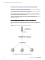
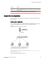
Point-to-point configuration............................................................... 379
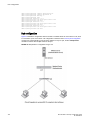
Hub configuration ............................................................................. 380
Security Commands..............................................................................................................383
base vrf......................................................................................................... 386
clear access-list receive accounting .............................................................386
Brocade NetIron Security Configuration Guide
53-1003255-03
11
clear dot1x-mka statistics............................................................................388
clear ipv6 access-list receive ..................................................................... 388
clear ipsec sa.............................................................................................. 389
clear ipsec statistics.................................................................................... 390
clear ipsec statistics tunnel......................................................................... 391
clear ike statistics........................................................................................392
clear ikev2 sa.............................................................................................. 393
comman-name............................................................................................ 394
country-name.............................................................................................. 395
clear macsec statistics................................................................................ 396
copy flash scp............................................................................................. 397
copy running-config scp.............................................................................. 398
copy flash scp............................................................................................. 399
copy scp running-config.............................................................................. 400
copy scp slot2............................................................................................. 401
copy scp slot1............................................................................................. 402
copy scp startup-config............................................................................... 403
copy slot1 scp............................................................................................. 404
copy slot2 scp............................................................................................. 405
copy startup-config scp............................................................................... 406
delete-certificate..........................................................................................407
dot1x-mka-enable....................................................................................... 408
email............................................................................................................409
eckeypair.....................................................................................................410
enable-mka................................................................................................. 411
fqdn............................................................................................................. 412
fingerprint.................................................................................................... 413
authentication..............................................................................................414
auth-proposal.............................................................................................. 415
cookie-challenge......................................................................................... 416
ikev2 dhgroup..............................................................................................417
encryption....................................................................................................418
exchange-max-time.....................................................................................419
http-url-cert..................................................................................................420
ikev2 integrity.............................................................................................. 421
limit..............................................................................................................422
ikev2 match identity.....................................................................................423
ikev2 method...............................................................................................424
policy...........................................................................................................425
ikev2 prf.......................................................................................................426
ikev2 profile.................................................................................................427
ikev2 proposal.............................................................................................428
ikev2 protected............................................................................................429
ikev2 retransmit-interval.............................................................................. 430
ikev2 retry-count..........................................................................................431
ip................................................................................................................. 432
ipsec esn-enable.........................................................................................433
ipsec ike-profile........................................................................................... 434
ipsec profile.................................................................................................435
ip receive access-list .................................................................................. 435
ip receive deactivate-acl-all ........................................................................436
ip receive delete-acl-all .............................................................................. 437
ip receive rebind-acl-all .............................................................................. 437
ipv6 receive access-list .............................................................................. 438
ipv6 receive deactivate-acl-all .................................................................... 439
ipv6 receive delete-acl-all ...........................................................................439
ipv6 receive rebind-acl-all .......................................................................... 440
key-server-priority....................................................................................... 441
12
Brocade NetIron Security Configuration Guide
53-1003255-03
log enable......................................................................................................442
location..........................................................................................................443
macsec cipher-suite...................................................................................... 444
macsec confidentiality-offset......................................................................... 445
macsec frame-validation............................................................................... 446
macsec replay-protection.............................................................................. 447
mka-cfg-group .............................................................................................. 448
mka-cfg-group .............................................................................................. 449
org-name.......................................................................................................450
org-unit-name................................................................................................451
pre-shared-key.............................................................................................. 452
pki entity........................................................................................................ 453
pki-entity........................................................................................................454
pki trustpoint..................................................................................................455
pki cert validate............................................................................................. 456
pki authenticate............................................................................................. 457
pki import.......................................................................................................458
pki import key ec........................................................................................... 459
state-name.................................................................................................... 460
subject-alt-name............................................................................................461
show access-list bindings .............................................................................461
show access-list receive accounting ............................................................ 462
show dot1x-mka config................................................................................. 463
show dot1x-mka group..................................................................................465
show dot1x-mka sessions brief..................................................................... 467
show dot1x-mka sessions ethernet...............................................................468
show ipv6 access-list bindings ..................................................................... 472
show ipv6 access-list receive accounting .................................................... 472
show ipsec statistics......................................................................................474
show ipsec statistics <LP>............................................................................ 475
show ipsec sa................................................................................................476
show ipsec proposal......................................................................................478
show ipsec profile..........................................................................................479
show ipsec ingress-config............................................................................. 480
show ipsec egress-config..............................................................................481
show ipsec ingress-spi-table......................................................................... 482
show ipsec egress-spi-table..........................................................................483
show ipsec error-count..................................................................................484
show interface tunnel.................................................................................... 485
show ikev2 statistics......................................................................................486
show ikev2 session....................................................................................... 487
show ikev2 sa................................................................................................488
show ikev2 proposal......................................................................................489
show ikev2 profile..........................................................................................490
show ikev2 policy.......................................................................................... 491
show macsec ethernet.................................................................................. 492
show macsec statistics ethernet................................................................... 494
show nht-table ipsec-based.......................................................................... 498
show pki certificates...................................................................................... 499
show pki entity...............................................................................................501
show pki key mypubkey................................................................................ 502
show pki trustpoint........................................................................................ 503
show statistics ipsec-tunnel...........................................................................505
suppress-acl-seq ..........................................................................................505
system-max ipv6-receive-cam ..................................................................... 506
tunnel mode ipsec ipv4................................................................................. 507
tunnel override-pkt-tos-ttl.............................................................................. 508
tunnel protection ipsec profile....................................................................... 509
Brocade NetIron Security Configuration Guide
53-1003255-03
13
vrf forwarding.............................................................................................. 510
Index.................................................................................................................................. 511
14
Brocade NetIron Security Configuration Guide
53-1003255-03
Preface
● Document conventions....................................................................................................15
● Brocade resources.......................................................................................................... 17
● Contacting Brocade Technical Support...........................................................................17
● Document feedback........................................................................................................ 18
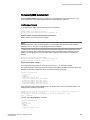
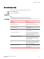
Document conventions
The document conventions describe text formatting conventions, command syntax conventions, and
important notice formats used in Brocade technical documentation.
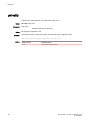
Text formatting conventions
Text formatting conventions such as boldface, italic, or Courier font may be used in the flow of the text
to highlight specific words or phrases.
Format
Description
bold text
Identifies command names
Identifies keywords and operands
Identifies the names of user-manipulated GUI elements
Identifies text to enter at the GUI
italic text
Identifies emphasis
Identifies variables
Identifies document titles
Courier font
Identifies CLI output
Identifies command syntax examples
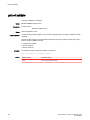
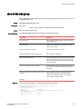
Command syntax conventions
Bold and italic text identify command syntax components. Delimiters and operators define groupings of
parameters and their logical relationships.
Convention
Description
bold text
Identifies command names, keywords, and command options.
italic text
Identifies a variable.
value
In Fibre Channel products, a fixed value provided as input to a command
option is printed in plain text, for example, --show WWN.
Brocade NetIron Security Configuration Guide
53-1003255-03
15
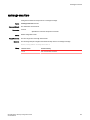
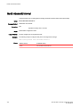
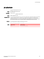
Notes, cautions, and warnings
Convention
Description
[]
Syntax components displayed within square brackets are optional.
Default responses to system prompts are enclosed in square brackets.
{x|y|z}
A choice of required parameters is enclosed in curly brackets separated by
vertical bars. You must select one of the options.
In Fibre Channel products, square brackets may be used instead for this
purpose.
x|y
A vertical bar separates mutually exclusive elements.
<>
Nonprinting characters, for example, passwords, are enclosed in angle
brackets.
...
Repeat the previous element, for example, member[member...].
\
Indicates a “soft” line break in command examples. If a backslash separates
two lines of a command input, enter the entire command at the prompt without
the backslash.
Notes, cautions, and warnings
Notes, cautions, and warning statements may be used in this document. They are listed in the order of
increasing severity of potential hazards.
NOTE
A Note provides a tip, guidance, or advice, emphasizes important information, or provides a reference
to related information.
ATTENTION
An Attention statement indicates a stronger note, for example, to alert you when traffic might be
interrupted or the device might reboot.
CAUTION
A Caution statement alerts you to situations that can be potentially hazardous to you or cause
damage to hardware, firmware, software, or data.
DANGER
A Danger statement indicates conditions or situations that can be potentially lethal or
extremely hazardous to you. Safety labels are also attached directly to products to warn of
these conditions or situations.
16
Brocade NetIron Security Configuration Guide
53-1003255-03
Brocade resources
Brocade resources
Visit the Brocade website to locate related documentation for your product and additional Brocade
resources.
You can download additional publications supporting your product at www.brocade.com. Select the
Brocade Products tab to locate your product, then click the Brocade product name or image to open the
individual product page. The user manuals are available in the resources module at the bottom of the
page under the Documentation category.
To get up-to-the-minute information on Brocade products and resources, go to MyBrocade. You can
register at no cost to obtain a user ID and password.
Release notes are available on MyBrocade under Product Downloads.
White papers, online demonstrations, and data sheets are available through the Brocade website.
Contacting Brocade Technical Support
As a Brocade customer, you can contact Brocade Technical Support 24x7 online, by telephone, or by email. Brocade OEM customers contact their OEM/Solutions provider.
Brocade customers
For product support information and the latest information on contacting the Technical Assistance
Center, go to http://www.brocade.com/services-support/index.html.
If you have purchased Brocade product support directly from Brocade, use one of the following methods
to contact the Brocade Technical Assistance Center 24x7.
Online
Telephone
E-mail
Preferred method of contact for nonurgent issues:
Required for Sev 1-Critical and Sev
2-High issues:
[email protected]
• My Cases through MyBrocade
•
Continental US: 1-800-752-8061
• Software downloads and licensing •
tools
Europe, Middle East, Africa, and
Asia Pacific: +800-AT FIBREE
(+800 28 34 27 33)
• Knowledge Base
•
For areas unable to access toll
free number: +1-408-333-6061
•
Toll-free numbers are available in
many countries.
Please include:
•
Problem summary
•
Serial number
•
Installation details
•
Environment description
Brocade OEM customers
If you have purchased Brocade product support from a Brocade OEM/Solution Provider, contact your
OEM/Solution Provider for all of your product support needs.
• OEM/Solution Providers are trained and certified by Brocade to support Brocade® products.
• Brocade provides backline support for issues that cannot be resolved by the OEM/Solution Provider.
Brocade NetIron Security Configuration Guide
53-1003255-03
17
Document feedback
• Brocade Supplemental Support augments your existing OEM support contract, providing direct
access to Brocade expertise. For more information, contact Brocade or your OEM.
• For questions regarding service levels and response times, contact your OEM/Solution Provider.
Document feedback
To send feedback and report errors in the documentation you can use the feedback form posted with
the document or you can e-mail the documentation team.
Quality is our first concern at Brocade and we have made every effort to ensure the accuracy and
completeness of this document. However, if you find an error or an omission, or you think that a topic
needs further development, we want to hear from you. You can provide feedback in two ways:
• Through the online feedback form in the HTML documents posted on www.brocade.com.
• By sending your feedback to [email protected].
Provide the publication title, part number, and as much detail as possible, including the topic heading
and page number if applicable, as well as your suggestions for improvement.
18
Brocade NetIron Security Configuration Guide
53-1003255-03
About This Document
● Supported hardware and software.................................................................................. 19
● Notice to the reader.........................................................................................................20
● How command information is presented in this guide.....................................................20
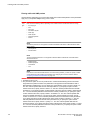
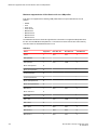
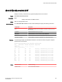
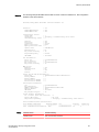
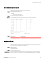
Supported hardware and software
The following hardware platforms are supported by this release of this guide:
TABLE 1
Brocade NetIron XMR Series
Brocade MLX Series
NetIron CES 2000 and NetIron CER 2000 Series
Brocade NetIron XMR 4000
Brocade MLX-4
Brocade NetIron CES 2024C
Brocade NetIron XMR 8000
Brocade MLX-8
Brocade NetIron CES 2024F
Brocade NetIron XMR 16000
Brocade MLX-16
Brocade NetIron CES 2048C
Brocade NetIron XMR 32000
Brocade MLX-32
Brocade NetIron CES 2048CX
Brocade MLXe-4
Brocade NetIron CES 2048F
Brocade MLXe-8
Brocade NetIron CES 2048FX
Brocade MLXe-16
Brocade NetIron CER 2024C
Brocade MLXe-32
Brocade NetIron CER-RT 2024C
Brocade NetIron CER 2024F
Brocade NetIron CER-RT 2024F
Brocade NetIron CER 2048C
Brocade NetIron CER-RT 2048C
Brocade NetIron CER 2048CX
Brocade NetIron CER-RT 2048CX
Brocade NetIron CER 2048F
Brocade NetIron CER-RT 2048F
Brocade NetIron CER 2048FX
Brocade NetIron CER-RT 2048FX
Supported software
For the complete list of supported features and the summary of enhancements and configuration notes
for this release, refer to the Brocade NetIron Unified R05.8.00 Release Notes.
Brocade NetIron Security Configuration Guide
53-1003255-03
19
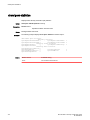
Notice to the reader
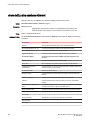
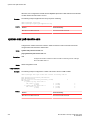
Notice to the reader
This document may contain references to the trademarks of the following corporations. These
trademarks are the properties of their respective companies and corporations.
These references are made for informational purposes only.
TABLE 2
Corporation
Referenced Trademarks and Products
Microsoft Corporation
Internet Explorer
Mozilla Corporation
Mozilla Firefox
Sun Microsystems
Java Runtime Environment
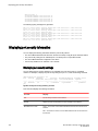
How command information is presented in this guide
For all new content, command syntax and parameters are documented in a separate command
reference section at the end of the publication.
In an effort to provide consistent command line interface (CLI) documentation for all products, Brocade
is in the process of preparing standalone Command References for the IP platforms. This process
involves separating command syntax and parameter descriptions from configuration tasks. Until this
process is completed, command information is presented in two ways:
• For all new content included in this guide, the CLI is documented in separate command pages. The
new command pages follow a standard format to present syntax, parameters, usage guidelines,
examples, and command history. Command pages are compiled in alphabetical order in a separate
command reference chapter at the end of the publication.
• Legacy content continues to include command syntax and parameter descriptions in the chapters
where the features are documented.
If you do not find command syntax information embedded in a configuration task, refer to the
command reference section at the end of this publication for information on CLI syntax and usage.
20
Brocade NetIron Security Configuration Guide
53-1003255-03
Securing Access to Management Functions
● Securing access methods............................................................................................... 23
● Restricting remote access to management functions..................................................... 26
● Setting passwords...........................................................................................................35
● Setting up local user accounts........................................................................................ 40
● Enabling strict password enforcement............................................................................ 42
● Web interface login lockout............................................................................................. 45
● Creating an encrypted all-numeric password..................................................................46
● Granting access by time of day.......................................................................................46
● Configuring SSL security for the Web Management Interface........................................ 46
● Configuring TACACS or TACACS+ security................................................................... 48
● Configuring RADIUS security..........................................................................................68
● Configuring AAA on the console..................................................................................... 85
● Configuring AAA authentication-method lists for login.................................................... 86
● Configuring authentication-method lists.......................................................................... 87
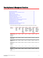
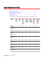
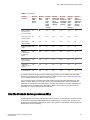
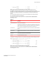
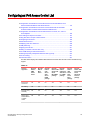
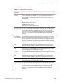
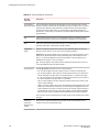
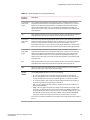
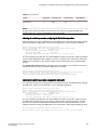
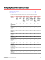
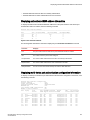
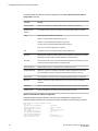
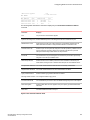
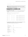
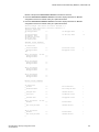
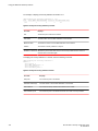
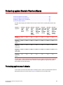
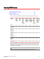
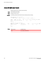
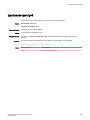
The table below displays the individual Brocade devices and the security features they support.
Features
supported
Brocade
NetIron
XMR
Series
Series
Brocade
NetIron
MLX
Series
Brocade
NetIron
CES
Series
2000
Series
BASE
package
Brocade
NetIron CES
Series 2000
Series
ME_PREM
package
Brocade
NetIron
CES Series
2000 Series
L3_PREM
package
Brocade
NetIron
CER
Series
2000
Series
Base
package
Brocade
NetIron
CER Series
2000 Series
Advanced
Services
package
Restricting Remote
Access to
Management
Functions
Yes
Yes
Yes
Yes
Yes
Yes
Yes
Setting Up Local
User Accounts
Yes
Yes
Yes
Yes
Yes
Yes
Yes
Web Management
Interface
Yes
Yes
No
No
No
No
No
SSL Security for
the Web
Management
Interface
Yes
Yes
No
No
No
No
No
TACACS or
TACACS+ Security
Yes
Yes
Yes
Yes
Yes
Yes
Yes
TACACS+
Validation of Reply
Packets
Yes
Yes
Yes
Yes
Yes
Yes
Yes
Brocade NetIron Security Configuration Guide
53-1003255-03
21
Securing Access to Management Functions
Features
supported
Brocade
NetIron
XMR
Series
Series
Brocade
NetIron
MLX
Series
Brocade
NetIron
CES
Series
2000
Series
BASE
package
Brocade
NetIron CES
Series 2000
Series
ME_PREM
package
Brocade
NetIron
CES Series
2000 Series
L3_PREM
package
Brocade
NetIron
CER
Series
2000
Series
Base
package
Brocade
NetIron
CER Series
2000 Series
Advanced
Services
package
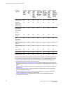
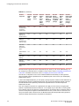
RADIUS Security
Yes
Yes
Yes
Yes
Yes
Yes
Yes
Designated
interface as the
source for all
RADIUS packets
Yes
Yes
Yes
Yes
Yes
Yes
Yes
Interactive multifactor RADIUS
security support
(e.g., for RSA
SecurID)
Yes
Yes
Yes
Yes
Yes
Yes
Yes
AAA on the
Console
Yes
Yes
Yes
Yes
Yes
Yes
Yes
AAA
AuthenticationMethod Lists
Yes
Yes
Yes
Yes
Yes
Yes
Yes
AES Encryption for
SNMPv3
Yes
Yes
Yes
Yes
Yes
Yes
Yes
AES Encryption for
SSHv2
Yes
Yes
Yes
Yes
Yes
Yes
Yes
DSA for SSHv2
Yes
Yes
Yes
Yes
Yes
Yes
Yes
RSA for SSHv2
Yes
Yes
Yes
Yes
Yes
Yes
Yes
Management VRF
Yes
Yes
Yes
Yes
Yes
Yes
Yes
By default, the Brocade devices have all management access disabled. This chapter explains how to
secure access to management functions on the Brocade devices. It contains the following sections:
• Securing access methods on page 23 lists the management access methods available on the
Brocade devices and the ways you can secure each one
• Restricting remote access to management functions on page 26 explains how to restrict access to
management functions from remote sources, including Telnet, the Web Management Interface, and
SNMP
• Setting passwords on page 35 explains how to set passwords for Telnet access and management
privilege levels
• Setting up local user accounts on page 40 explains how to define user accounts to regulate who
can access management functions.
• Configuring TACACS or TACACS+ security on page 48 explains how to configure TACACS or
TACACS+ authentication, authorization, and accounting.
• Configuring RADIUS security on page 68 explains how to configure RADIUS authentication,
authorization, and accounting.
22
Brocade NetIron Security Configuration Guide
53-1003255-03
Securing access methods
• Configuring AAA on the console on page 85
• Configuring authentication-method lists on page 87 explains how to set the order that
authentication methods are consulted when more than one is used with an access method.
NOTE
For the Brocade devices, RADIUS Challenge is supported for 802.1x authentication for login
authentication. Also, multiple challenges are supported for TACACS+ and RADIUS login authentication.
Securing access methods
The table below lists the management access methods available on the Brocade devices, how they are
secured by default, and the ways in which they can be secured.
Access method
How the access method is secured by
default
Ways to secure the
access method
Serial access to the CLI
Not secured
Establish passwords for
management privilege
levels
Establish username and
password to log in to the
console.
Access to the Privileged EXEC and CONFIG Not secured
levels of the CLI
Establish a password for
Telnet access to the CLI
Establish passwords for
management privilege
levels
Set up local user
accounts
Configure TACACS or
TACACS+ security
Configure RADIUS
security
Telnet access
Telnet server is turned off by default.
Regulate Telnet access
using ACLs
Allow Telnet access only from specific IP
addresses
Allow Telnet access only to clients
connected to a specific VLAN
Regulate telnet access using Management
VRF.
Brocade NetIron Security Configuration Guide
53-1003255-03
23
Securing Access to Management Functions
Access method
How the access method is secured by
default
Ways to secure the
access method
Not configured
Configure DSA or RSA
host keys
SNMP read or read-write community
strings
Regulate Web
management access
using ACLs
Disable Telnet access
Establish a password for Telnet access
Establish passwords for privilege levels of
the CLI
Set up local user accounts
Configure TACACS or TACACS+ security
Configure RADIUS security
Secure Shell (SSH) access
For more information on SSH, refer to
Brocade NetIron Switching Configuration
Guide .
Disable SSH server.
Password Authentication
Public key authentication using client's public
key
(excludes use of username and password
credentials)
Regulate SSH access using ACLs
Allow SSH access only from specific IP
addresses
Establish passwords for privilege levels of
the CLI
Set up local user accounts
Configure TACACS or TACACS+ security
Configure RADIUS security
Web management access
Web server is turned off by default.
Note : Web access is not allowed in
Brocade NetIron CES Series and
Brocade NetIron CER Series devices.
Allow Web management access only from
specific IP addresses
24
Brocade NetIron Security Configuration Guide
53-1003255-03
Securing Access to Management Functions
Access method
How the access method is secured by
default
Ways to secure the
access method
SNMP read or read-write community
strings and the password to the Super
User privilege level
Regulate SNMP access
using ACLs
Allow Web management access only to
clients connected to a specific VLAN
Disable Web management access
Configure SSL security for the Web
Management Interface
Set up local user accounts
Establish SNMP read or read-write
community strings for SNMP versions 1 and
2
Configure AAA command for Web access
Configure TACACS or TACACS+ security
Configure RADIUS security
SNMP (Brocade Network Advisor) access
NOTE
SNMP read or read-write community
strings are always required for SNMP
access to the device.
SNMP access is disabled by default.
Allow SNMP access
only from specific IP
addresses
Disable SNMP access
Allow SNMP access
only to clients connected
to a specific VLAN
Establish passwords to
management levels of
the CLI
Set up local user
accounts
Configure AAA
command for SNMP
access
Establish SNMP read or
read-write community
strings
TFTP access
Not secured
Allow TFTP access only
to clients connected to a
specific VLAN
Secure Copy access
Secured access if SSH server is enabled
Configure DSA or RSA
host keys
Brocade NetIron Security Configuration Guide
53-1003255-03
25
Restricting remote access to management functions
Access method
How the access method is secured by
default
Ways to secure the
access method
Disable SSH server.
Password Authentication
Public key authentication using client's public
key
(excludes use of username and password
credentials)
Regulate SSH access using ACLs
Allow SSH access only from specific IP
addresses
Establish passwords for privilege levels of
the CLI
Set up local user accounts
Configure TACACS or TACACS+ security
Configure RADIUS security
Restricting remote access to management functions
You can restrict access to management functions from remote sources, including Telnet, SSH, the
Web Management Interface, and SNMP. The following methods for restricting remote access are
supported:
•
•
•
•
•
Using ACLs to restrict Telnet, SSH, Web Management Interface, or SNMP access.
Allowing remote access only from specific IP addresses.
Allowing remote access only to clients connected to a specific VLAN.
Specifically disabling Telnet, SSH, Web Management Interface, or SNMP access to the device.
Using Management VRF to restrict access from certain physical ports.
NOTE
The Web Management Interface is only supported on the Brocade NetIron XMR Series and Brocade
NetIron MLX Series devices.
NOTE
If the display on the front panel of the Web Management Interface is distorted, manually click on the
link to reset the display to normal.
26
Brocade NetIron Security Configuration Guide
53-1003255-03
Using ACLs to restrict remote access
Using ACLs to restrict remote access
You can use ACLs to control the following access methods to management functions on the Brocade
device:
•
•
•
•
Telnet access
SSH access
Web management access
SNMP access
Follow the steps listed below to configure access control for these management access methods.
1. Configure an ACL with the IP addresses you want to allow to access the device. You can specify a
numbered standard IPv4 ACL, or a named standard IPv4 ACL.
2. Configure a Telnet access group, SSH access group, web access group, and SNMP community
strings for SNMPv1, SNMPv2c or SNMPv3 user. Each of these configuration items accepts an ACL
as a parameter. The ACL contains entries that identify the IP addresses that can use the access
method.
The following sections present examples of how to secure management access using ACLs. Refer to
"Access Control List" chapter "Configuring an IPv6 Access Control List" for more information on
configuring ACLs.
NOTE
ACL filtering for remote management access is done in hardware.
Using an ACL to restrict Telnet access
To configure an ACL that restricts Telnet access to the device, enter commands such as the following:
device(config)#
device(config)#
device(config)#
device(config)#
device(config)#
device(config)#
device(config)#
access-list 10 deny host 10.157.22.32
access-list 10 deny 10.157.23.0 0.0.0.255
access-list 10 deny 10.157.24.0 0.0.0.255
access-list 10 deny 10.157.25.0/24
access-list 10 permit any
telnet access-group 10
write memory
The commands configure ACL 10, then apply it as the access list for Telnet access. The device allows
Telnet access to all IP addresses except those listed in ACL 10.
Syntax: [no] telnet access-group { num | name }
The num variable specifies the number of a standard IPv4 ACL, 1 - 99.
The name variable specifies the standard IPv4 access list name.
NOTE
ACLs for Telnet sessions will be applied only to inbound sessions.
To configure a more restrictive ACL, create permit entries and omit the permit any entry at the end of
the ACL.
device(config)#
device(config)#
device(config)#
device(config)#
Brocade NetIron Security Configuration Guide
53-1003255-03
access-list
access-list
access-list
access-list
10
10
10
10
permit
permit
permit
permit
host 10.157.22.32
10.157.23.0 0.0.0.255
10.157.24.0 0.0.0.255
10.157.25.0/24
27
Using an ACL to restrict SSH access
device(config)# telnet access-group 10
device(config)# write memory
The ACL in the example permits Telnet access only from the IPv4 addresses in the permit entries and
denies Telnet access from all other IP addresses.
Using an ACL to restrict SSH access
To configure an ACL that restricts SSH access to the device, enter commands such as the following:
device(config)#
device(config)#
device(config)#
device(config)#
device(config)#
device(config)#
access-list 12 deny host 10.157.22.98
access-list 12 deny 10.157.23.0 0.0.0.255
access-list 12 deny 10.157.24.0/24
access-list 12 permit any
ssh access-group 12
write memory
Syntax: [no] ssh access-group {num | name }
The num variable specifies the number of a standard IPv4 ACL, 1 - 99.
The name variable specifies the standard IPv4 access list name.
hese commands configure ACL 12, then apply the ACL as the access list for SSH access. The device
denies SSH access from the IPv4 addresses listed in ACL 12 and permits SSH access from all other
IP addresses. Without the last ACL entry for permitting all packets, this ACL would deny SSH access
from all IP addresses.
NOTE
In this example, the command ssh access-groupcould have been used to apply the ACL configured
in the example for Telnet access. You can use the same ACL multiple times.
Using an ACL to restrict Web management access
NOTE
The Web Management Interface is only supported on the Brocade NetIron XMR Series and Brocade
NetIron MLX Series devices.
To configure an ACL that restricts Web management access to the device, enter commands such as
the following:
device(config)#
device(config)#
device(config)#
device(config)#
device(config)#
device(config)#
access-list 12 deny host 10.157.22.98
access-list 12 deny 10.157.23.0 0.0.0.255
access-list 12 deny 10.157.24.0/24
access-list 12 permit any
web access-group 12
write memory
Syntax: [no] web access-group { num | name }
The num variable specifies the number of a standard IPv4 ACL, 1 - 99.
The name variable specifies the standard IPv4 access list name.
These commands configure ACL 12, then apply the ACL as the access list for Web management
access. The device denies Web management access from the IP addresses listed in ACL 12 and
28
Brocade NetIron Security Configuration Guide
53-1003255-03
Using ACLs to restrict SNMP access
permits Web management access from all other IP addresses. Without the last ACL entry for permitting
all packets, this ACL would deny Web management access from all IP addresses.
Using ACLs to restrict SNMP access
To restrict SNMP access to the device using ACLs, enter commands such as the following.
NOTE
The syntax for using ACLs for SNMP access is different from the syntax for controlling Telnet, SSH, and
Web management access using ACLs.
device(config)#
device(config)#
device(config)#
device(config)#
device(config)#
device(config)#
device(config)#
device(config)#
device(config)#
device(config)#
access-list 25 deny host 10.157.22.98
access-list 25 deny 10.157.23.0 0.0.0.255
access-list 25 deny 10.157.24.0 0.0.0.255
access-list 25 permit any
access-list 30 deny 10.157.25.0 0.0.0.255
access-list 30 deny 10.157.26.0/24
access-list 30 permit any
snmp-server community public ro 25
snmp-server community private rw 30
write memory
These commands configure ACLs 25 and 30, then apply the ACLs to community strings. ACL 25 is
used to control read-only access using the "public" community string. ACL 30 is used to control readwrite access using the "private" community string.
Syntax: [no] snmp-server community string { ro | rw } { standard-acl-name | standard-acl-id }
The string variable specifies the SNMP community string the user must enter to gain SNMP access.
The ro parameter indicates that the community string is for read-only ("get") access. The rw parameter
indicates the community string is for read-write ("set") access.
The standard-acl-name or standard-acl-id variable specifies which ACL will be used to filter incoming
SNMP packets.
The standard-acl-id variable specifies the number of a standard IPv4 ACL, 1 - 99.
The standard-acl-name variable specifies the standard IPv4 access list name.
NOTE
When snmp-server community is configured, all incoming SNMP packets are validated first by their
community strings and then by their bound ACLs. Packets are permitted if no filters are configured for
an ACL.
Defining the console idle time
By default, a Brocade device does not time out serial console sessions. A serial session remains open
indefinitely until you close it. You can however define how many minutes a serial management session
can remain idle before it is timed out.
To configure the idle time for a serial console session, use the following command.
device(config)# console timeout 120
Syntax: [no] console timeout value
Brocade NetIron Security Configuration Guide
53-1003255-03
29
Restricting remote access to the device to specific IP addresses
Possible values: 0 - 240 minutes
Default value: 0 minutes (no timeout)
NOTE
The standard for the idle-timeout RADIUS attribute is for it to be implemented in seconds as opposed
to the minutes that the Brocade device uses. If this attribute is used for setting idle time instead of this
configuration, the value from the idle-timeout RADIUS attribute will be converted from seconds to
minutes and truncated to the nearest minute.
Restricting remote access to the device to specific IP addresses
By default, a Brocade device does not control remote management access based on the IP address of
the managing device. You can restrict remote management access to a single IP address for the
following access methods:
•
•
•
•
Telnet access
Web management access
SNMP access
SSH access
In addition, if you want to restrict all three access methods to the same IP address, you can do so
using a single command.
The following examples show the CLI commands for restricting remote access. You can specify only
one IP address with each command. However, you can enter each command ten times to specify up
to ten IP addresses.
NOTE
You cannot restrict remote management access using the Web Management Interface.
Restricting Telnet access to a specific IP address
To allow Telnet access to the Brocade device only to the host with IP address 10.157.22.39, enter the
following command.
device(config)# telnet client 10.157.22.39
Syntax: [no] telnet client ip-address
Restricting SSH access to a specific IP address
To allow SSH access to the Brocade device only to the host with IP address 10.157.22.39, enter the
following command.
device(config)# ip ssh client 10.157.22.39
Syntax: [no] ip ssh client ip-address
30
Brocade NetIron Security Configuration Guide
53-1003255-03
Restricting Web management access to a specific IP address
Restricting Web management access to a specific IP address
NOTE
The Web Management Interface is only supported on the Brocade NetIron XMR Series and Brocade
NetIron MLX Series devices.
To allow Web management access to the Brocade device only to the host with IP address
10.157.22.26, enter the following command.
device(config)# web client 10.157.22.26
Syntax: [no] web client ip-address
Restricting SNMP access to a specific IP address
To allow SNMP access (which includes Brocade Network Advisor) to the Brocade device only to the
host with IP address 10.157.22.14, enter the following command.
device(config)# snmp-client 10.157.22.14
Syntax: [no] snmp-client ip-address
Restricting all remote management access to a specific IP address
NOTE
The Web Management Interface is only supported on the Brocade NetIron XMR Series and Brocade
NetIron MLX Series devices.
To allow Telnet, SSH, Web, and SNMP management access to the Brocade device only to the host with
IP address 10.157.22.69, you can enter three separate commands (one for each access type) or you
can enter the following command.
device(config)# all-client 10.157.22.69
Syntax: [no] all-client ip-address
Defining the Telnet idle time
You can define how many minutes a Telnet session can remain idle before it is timed out. An idle Telnet
session is a session that is still sending TCP ACKs in response to keepalive messages from the device,
but is not being used to send data.
To configure the idle time for a Telnet session, use the following command.
device(config)# telnet timeout 120
Syntax: [no] telnet timeout 0 - 240
Possible values: 0 - 240 minutes
Default value: 0 minutes (no timeout)
Brocade NetIron Security Configuration Guide
53-1003255-03
31
Specifying the maximum login attempts for Telnet access
NOTE
The standard for the idle-timeout RADIUS attribute is for it to be implemented in seconds as opposed
to the minutes that the Brocade device uses. If this attribute is used for setting idle time instead of this
configuration, the value from the idle-timeout RADIUS attribute will be converted from seconds to
minutes and truncated to the nearest minute.
Specifying the maximum login attempts for Telnet access
If you are connecting to the Brocade device using Telnet, the device prompts you for a username and
password. By default, you have up to 4 chances to enter a correct username and password. If you do
not enter a correct username or password after 4 attempts, the Brocade device disconnects the Telnet
session.
You can specify the number of attempts a Telnet user has to enter a correct username and password
before the Brocade device disconnects the Telnet session. For example, to allow a Telnet user up to 5
chances to enter a correct username and password, enter the following command.
device(config)# telnet login-retries 5
Syntax: [no] telnet login-retries number
You can specify from 0 - 5 attempts. The default is 4 attempts.
Restricting remote access to the device to specific VLAN IDs
You can restrict management access to a Brocade device to ports within a specific port-based VLAN.
VLAN-based access control applies to the following access methods:
•
•
•
•
Telnet access
Web management access
SNMP access
TFTP access
By default, access is allowed for all the methods listed above on all ports. Once you configure security
for a given access method based on VLAN ID, access to the device using that method is restricted to
only the ports within the specified VLAN.
VLAN-based access control works in conjunction with other access control methods. For example,
suppose you configure an ACL to permit Telnet access only to specific client IP addresses, and you
also configure VLAN-based access control for Telnet access. In this case, the only Telnet clients that
can access the device are clients that have one of the IP addresses permitted by the ACL and are
connected to a port that is in a permitted VLAN. Clients who have a permitted IP address but are
connected to a port in a VLAN that is not permitted still cannot access the device through Telnet.
Restricting Telnet access to a specific VLAN
To allow Telnet access only to clients in a specific VLAN, enter a command such as the following.
device(config)# telnet server enable vlan 10
The command configures the device to allow Telnet management access only to clients connected to
ports within port-based VLAN 10. Clients connected to ports that are not in VLAN 10 are denied
management access.
32
Brocade NetIron Security Configuration Guide
53-1003255-03
Restricting Web management access to a specific VLAN
Syntax: [no] telnet server enable vlan vlan-id
Restricting Web management access to a specific VLAN
NOTE
The Web Management Interface is only supported on the Brocade NetIron XMR Series and Brocade
NetIron MLX Series devices.
To allow Web management access only to clients in a specific VLAN, enter a command such as the
following.
device(config)# web-management enable vlan 10
The command configures the device to allow Web management access only to clients connected to
ports within port-based VLAN 10. Clients connected to ports that are not in VLAN 10 are denied
management access.
Syntax: [no] web-management enable vlan vlan-id
Restricting SNMP access to a specific VLAN
To allow SNMP access only to clients in a specific VLAN, enter a command such as the following.
device(config)# snmp-server enable vlan 40
The command configures the device to allow SNMP access only to clients connected to ports within
port-based VLAN 40. Clients connected to ports that are not in VLAN 40 are denied access.
Syntax: [no] snmp-server enable vlan vlan-id
Restricting TFTP access to a specific VLAN
To allow TFTP access only to clients in a specific VLAN, enter a command such as the following.
device(config)# tftp client enable vlan 40
The command in this example configures the device to allow TFTP access only to clients connected to
ports within port-based VLAN 40. Clients connected to ports that are not in VLAN 40 are denied access.
Syntax: [no] tftp client enable vlan vlan-id
Enabling specific access methods
You can specifically enable the following access methods:
• Telnet access
• Web management access
• SNMP access
NOTE
If you do not enable Telnet access, you can access the CLI using a serial connection to the
management module. If you do not enable SNMP access, you will not be able to use Brocade Network
Advisor or third-party SNMP management applications.
Brocade NetIron Security Configuration Guide
53-1003255-03
33
Enabling Telnet access
Enabling Telnet access
Telnet access is disabled by default. You can use a Telnet client to access the CLI on the device over
the network.
To enable Telnet operation, enter the following command.
device(config)# telnet server
If you do not plan to use the CLI over the network and want to disable Telnet access to prevent others
from establishing CLI sessions with the device , enter the following command.
device(config)# no telnet server
Syntax: [no] telnet-server
Enabling Web management access for a Brocade device
Web Management is disabled by default. You can enable it through HTTP or HTTPS as described in
the following sections.
NOTE
The Web Management Interface is only supported on the Brocade NetIron XMR Series and Brocade
NetIron MLX Series devices
Web management through HTTP
To allow web management through HTTP for a Brocade device, you enable web management as
shown in the following command.
device(config)# web-management
Syntax: [no] web-management [ http | https ]
Using the web-management command without the http or https option makes web management
available for both.
The http option specifies that web management is enabled for HTTP access.
The https option specifies that web management is enabled for HTTPS access.
Web management through HTTPS
The following encryption cipher algorithm are supported for HTTPS. They are listed in order of
preference:
• 3des-cbc: Triple-DES
• rc4-des: RC4 DES
To allow web management through HTTPS for a Brocade device you must enable web management
as shown in Web management through HTTP on page 34. Additionally, you must generate a crypto
SSL certificate or import digital certificates issued by a third-party Certificate Authority (CA).
To generate a crypto SSL certificate use the following command.
device(config)# crypto-ssl certificate generate
Syntax: [no] crypto-ssl certificate [ generate | zeroize ]
34
Brocade NetIron Security Configuration Guide
53-1003255-03
Disabling Web management access by HP ProCurve Manager
Using the web-management command without the http or https option makes web management
available for both.
The generate parameter generates an ssl certificate.
The zeroize parameter deletes the currently operative ssl certificate.
To import a digital certificate issued by a third-party Certificate Authority (CA) and save it in the flash
memory, use the following command.
Brocade# copy tftp flash 10.10.10.1 cacert.pem server-certificate
Syntax: copy tftp flash ip-address file-name server-certificate
The ip-address variable is the IP address of the TFTP server where the digital certificate file is being
downloaded from.
The file-name variable is the file name of the digital certificate that you are importing to the device.
Disabling Web management access by HP ProCurve Manager
By default, TCP ports 80 is enabled on the Brocade device. TCP port 80 (HTTP) allows access to the
device’s Web Management Interface.
By default, TCP port 280 for HP Top tools is disabled. This tool allows access to the device by HP
ProCurve Manager.
The no web-management command disables both TCP ports. However, if you want to disable only
port 280 and leave port 80 enabled, use the hp-top-tools option with the command.
device(config)# no web-management hp-top-tools
Syntax: [no] web-management hp-top-tools
The hp-top-tools parameter disables TCP port 280.
Enabling SNMP access
SNMP is disabled by default on the Brocade devices. SNMP is required if you want to manage a
Brocade device using Brocade Network Advisor.
To enable SNMP management of the device.
device(config)#snmp-server
To later disable SNMP management of the device.
device(config)#no snmp-server
Syntax: [no] snmp-server
Setting passwords
Passwords can be used to secure the following access methods:
Brocade NetIron Security Configuration Guide
53-1003255-03
35
Setting a Telnet password
• Telnet access can be secured by setting a Telnet password. Refer to Setting a Telnet password on
page 36.
• Access to the Privileged EXEC and CONFIG levels of the CLI can be secured by setting passwords
for management privilege levels. Refer to Setting passwords for management privilege levels on
page 36.
This section also provides procedures for enhancing management privilege levels, recovering from a
lost password, and disabling password encryption.
NOTE
You also can configure up to 16 user accounts consisting of a user name and password, and assign
each user account a management privilege level. Refer to Setting up local user accounts on page
40.
Setting a Telnet password
By default, the device does not require a user name or password when you log in to the CLI using
Telnet.
To set the password "letmein" for Telnet access to the CLI, enter the following command at the global
CONFIG level.
device(config)# enable telnet password letmein
Syntax: [no] enable telnet password string
NOTE
If enable strict-password-enforcement is enabled, when a user is logged in and is attempting to
change their own user password, the following prompt is displayed: Enter old password. After
validating the old password, the following prompt is displayed: Enter new password.
Suppressing Telnet connection rejection messages
By default, if a Brocade device denies Telnet management access to the device, the software sends a
message to the denied Telnet client. You can optionally suppress the rejection message. When you
enable the option, a denied Telnet client does not receive a message from the Brocade device.
Instead, the denied client simply does not gain access.
To suppress the connection rejection message sent by the device to a denied Telnet client, enter the
following command at the global CONFIG level of the CLI.
device(config)# telnet server suppress-reject-message
Syntax: [no] telnet server suppress-reject-message
Setting passwords for management privilege levels
You can set one password for each of the following management privilege levels:
36
Brocade NetIron Security Configuration Guide
53-1003255-03
Securing Access to Management Functions
• Super User level - Allows complete read-and-write access to the system. This is generally for
system administrators and is the only management privilege level that allows you to configure
passwords.
• Port Configuration level - Allows read-and-write access for specific ports but not for global (systemwide) parameters.
• Read Only level - Allows access to the Privileged EXEC mode and CONFIG mode of the CLI but
only with read access.
You can assign a password to each management privilege level. You also can configure up to 16 user
accounts consisting of a user name and password, and assign each user account to one of the three
privilege levels. Refer to Setting up local user accounts on page 40.
NOTE
You must use the CLI to assign a password for management privilege levels. You cannot assign a
password using the Web Management Interface.
If you configure user accounts in addition to privilege level passwords, the device will validate a user’s
access attempt using one or both methods (local user account or privilege level password), depending
on the order you specify in the authentication-method lists. Refer to Configuring authentication-method
lists on page 87.
Follow the steps listed below to set passwords for management privilege levels.
1. At the opening CLI prompt, enter the following command to change to the Privileged level of the
EXEC mode.
device> enable
device#
2. Access the CONFIG level of the CLI by entering the following command.
device# configure terminal
device(config)#
3. Enter the following command to set the Super User level password.
device(config)# enable super-user-password text
NOTE
You must set the Super User level password before you can set other types of passwords. The
Super User level password can be an alphanumeric string, but cannot begin with a number.
4. Enter the following commands to set the Port Configuration level and Read Only level passwords.
device(config)# enable port-config-password text
device(config)# enable read-only-password text
NOTE
When enable strict-password-enforcement is in effect and you create a password using the
following commands, the characters you type are masked. The examples in this guide do not mask
the passwords for clarity.
Syntax: enable super-user-password text
Syntax: enable port-config-password text
Syntax: enable read-only-password text
Brocade NetIron Security Configuration Guide
53-1003255-03
37
Augmenting management privilege levels
NOTE
If you forget your Super User level password, refer to Recovering from a lost password on page
39.
NOTE
When enable strict-password-enforcement is enabled, the user uses the enable super-userpassword to log in, and the enable-super-user password command is used, the following prompt
is displayed: Enter old password. After validating the old password, the following prompt is
displayed: Enter new password.
Augmenting management privilege levels
Each management privilege level provides access to specific areas of the CLI by default:
• Super User level provides access to all commands and displays.
• Port Configuration level gives access to the following:
‐
The User EXEC and Privileged EXEC levels
‐
The port-specific parts of the CONFIG level
‐
All interface configuration levels
• Read Only level gives access to the following:
‐
The User EXEC and Privileged EXEC levels
You can grant additional access to a privilege level on an individual command basis. To grant the
additional access, you specify the privilege level you are enhancing, the CLI level that contains the
command, and the individual command.
NOTE
This feature applies only to management privilege levels on the CLI. You cannot augment
management access levels for the Web Management Interface.
To enhance the Port Configuration privilege level so users also can enter IP commands at the global
CONFIG level.
device(config)# privilege configure level 4 ip
In this command, configure specifies that the enhanced access is for a command at the global
CONFIG level of the CLI. The level 4 parameter indicates that the enhanced access is for
management privilege level 4 (Port Configuration). All users with Port Configuration privileges will
have the enhanced access. The ip parameter indicates that the enhanced access is for the IP
commands. Users who log in with valid Port Configuration level user names and passwords can enter
commands that begin with "ip" at the global CONFIG level.
Syntax: [no] privilege cli-level level privilege-level command-string
The cli-level parameter specifies the CLI level and can be one of the following values:
•
•
•
•
•
•
•
38
exec - EXEC level; for example, device#
configure - CONFIG level; for example, device(config)#
interface - Interface level; for example, device(config-if-e10000-6)#
virtual-interface - Virtual-interface level; for example, device(config-vif-6)#
rip-router - RIP router level; for example, device(config-rip-router)#
ospf-router - OSPF router level; for example, device(config-ospf-router)#
bgp-router - BGP4 router level; for example,device(config-bgp-router)#
Brocade NetIron Security Configuration Guide
53-1003255-03
Recovering from a lost password
•
•
•
•
•
•
port-vlan - Port-based VLAN level; for example, device(config-vlan)#
protocol-vlan - Protocol-based VLAN level
dot1x
loopback-interface
tunnel-interface
vrrp-router
The privilege-level indicates the number of the management privilege level you are augmenting. You
can specify one of the following:
• 0 - Super User level (full read-write access)
• 4 - Port Configuration level
• 5 - Read Only level
The command-string parameter specifies the command you are allowing users with the specified
privilege level to enter. To display a list of the commands at a CLI level, enter "?" at that level's
command prompt.
Recovering from a lost password
Recovery from a lost password requires direct access to the serial port and a system reset.
NOTE
You can perform this procedure only from the CLI.
Follow the steps listed below to recover from a lost password.
1. Start a CLI session over the serial interface to the device.
2. Reboot the device.
3. At the initial boot prompt at system startup, enter b to enter the boot monitor mode.
4. Enter no password at the prompt. (You cannot abbreviate this command.) This command will cause
the device to bypass the system password check.
5. Enter boot system flash primary at the prompt, and enter y when asked "Are you sure?".
6. After the console prompt reappears, assign a new password.
Displaying the SNMP community string
If you want to display the SNMP community string, enter the following commands.
device(config)# enable password-display
device(config)# show snmp server
The enable password-display command enables display of the community string, but only in the
output of the show snmp server command. Display of the string is still encrypted in the startup
configuration file and running configuration. Enter the command at the global CONFIG level of the CLI.
Disabling password encryption
When you configure a password, then save the configuration to the device’s flash memory, the
password is also saved to flash as part of the configuration file. By default, the passwords are encrypted
so that the passwords cannot be observed by another user who displays the configuration file. Even if
someone observes the file while it is being transmitted over TFTP, the password is encrypted.
Brocade NetIron Security Configuration Guide
53-1003255-03
39
Specifying a minimum password length
If you want to remove the password encryption, you can disable encryption by entering the following
command.
device(config)# no service password-encryption
Syntax: [no] service password-encryption
Specifying a minimum password length
By default, the device imposes no minimum length on the Line (Telnet), Enable, or Local passwords.
You can configure the device to require that Line, Enable, and Local passwords be at least a specified
length.
For example, to specify that the Line, Enable, and Local passwords be at least 8 characters, enter the
following command.
device(config)# enable password-min-length 8
Syntax: [no] enable password-min-length number-of-characters
The number-of-characters can be from 1 - 48.
Setting up local user accounts
You can define up to 32 local user accounts on a Brocade device. User accounts regulate who can
access the management functions in the CLI using the following methods:
•
•
•
•
•
Telnet access
SSH access
Console access
Web management access
SNMP access
Local user accounts provide greater flexibility for controlling management access to the Brocade
device than do management privilege level passwords and SNMP community strings of SNMP
versions 1 and 2. You can continue to use the privilege level passwords and the SNMP community
strings as additional means of access authentication. Alternatively, you can choose not to use local
user accounts and instead continue to use only the privilege level passwords and SNMP community
strings. Local user accounts are backward-compatible with configuration files that contain privilege
level passwords. Refer to Setting passwords for management privilege levels on page 36.
If you configure local user accounts, you also need to configure an authentication-method list for
Telnet access, Web management access, and SNMP access. Refer to Configuring authenticationmethod lists on page 87.
For each local user account, you specify a user name which can have up to 48 characters. You also
can specify the following parameters:
• A password
• A management privilege level, which can be one of the following:
40
Brocade NetIron Security Configuration Guide
53-1003255-03
Configuring a local user account
‐
‐
‐
Super User level - Allows complete read-and-write access to the system. This is generally
for system administrators and is the only privilege level that allows you to configure
passwords. This is the default.
Port Configuration level - Allows read-and-write access for specific ports but not for global
(system-wide) parameters.
Read Only level - Allows access to the Privileged EXEC mode and CONFIG mode but only
with read access.
Configuring a local user account
To configure a local user account, enter a command such as the following at the global CONFIG level of
the CLI.
device(config)# username wonka password willy
This command adds a local user account with the user name "wonka" and the password "willy". This
account has the Super User privilege level; this user has full access to all configuration and display
features.
NOTE
If you configure local user accounts, you must grant Super User level access to at least one account
before you add accounts with other privilege levels. You need the Super User account to make further
administrative changes.
device(config)# username waldo privilege 5 password whereis
This command adds a user account for user name "waldo", password "whereis", with the Read Only
privilege level. Waldo can look for information but cannot make configuration changes.
Syntax: [no] username user-string privilege privilege-level password | nopassword passwordstring
Enter up to 48 characters for user-string.
The privilege parameter specifies the privilege level for the account. You can specify one of the
following:
• 0 - Super User level (full read-write access)
• 4 - Port Configuration level
• 5 - Read Only level
The default privilege level is 0. If you want to assign Super User level access to the account, you can
enter the command without privilege 0, as shown in the command example above.
The password | nopassword parameter indicates whether the user must enter a password. If you
specify password, enter the string for the user's password.
NOTE
You must be logged on with Super User access (privilege level 0) to add user accounts or configure
other access parameters.
To display user account information, enter the following command.
device(config)# show users
Syntax: show users
Brocade NetIron Security Configuration Guide
53-1003255-03
41
Note about changing local user passwords
Note about changing local user passwords
The Brocade device stores not only the current password configured for a local user, but the previous
two passwords configured for the user as well. The local user's password cannot be changed to one of
the stored passwords.
Consequently, if you change the password for a local user, you must select a password that is
different from the current password, as well as different from the previous two passwords that had
been configured for that user.
For example, say local user waldo originally had a password of "whereis", and the password was
subsequently changed to "whois", then later changed to "whyis". If you change waldo's password
again, you cannot change it to "whereis", "whois", or "whyis".
The current and previous passwords are stored in the device’s running configuration file in encrypted
form.
device# show run
...
username waldo password 8 $1$Ro2..Ox0$udBu7pQT5XyuaXMUiUHy9. history
$1$eq...T62$IfpxIcxnDWX7CSVQKIodu. $1$QD3..2Q0$DYxgxCI64ZOSsYmSSaA28/
...
In the running configuration file, the user’s previous two passwords are displayed in encrypted form
following the history parameter.
Enabling strict password enforcement
Additional security to the local username and password by configuring the enable strict-passwordenforcement CLI command. Note the rules for passwords if the strict password is disabled and when
it is enabled.
Configuring the strict password rules
Use the enablestrict-password-enforcement command to enable the strict password enforcement
feature. Enter a command such as the following.
device(config)# enable strict-password-enforcement
Syntax: [no] enable strict-password-enforcement
This feature is disabled by default.
When enabled, the system verifies uniqueness against the history of passwords of the user whose
password is being set. Passwords must not share four or more concurrent characters with any other
password configured for that user on the device. If the user tries to create a password which shares
four or more concurrent characters for that user, the following error message is returned:
Error - The substring <str> within the password has been used earlier, please choose
a different password.
Also, if the user tries to configure a password that was previously configured, the local user account
configuration is not allowed and the following message is displayed.
Error - This password was used earlier, please choose a different password.
When you create a password, the characters you type are masked.
42
Brocade NetIron Security Configuration Guide
53-1003255-03
Password history
: To assign a password for a user account.
device(config)# username sandy password [Enter]
Enter new password: ********
Syntax: [no] username name password
Enter a password such as TesT12$! that contains the required character combination.
NOTE
If enable strict-password-enforcement is enabled, when a user is logged in and is attempting to change
their own user password, the following prompt is displayed: Enter old password. After validating the old
password, the following prompt is displayed: Enter new password.
Password history
If the enable strict-password-enforcement command is enabled, the CLI keeps the last 15 passwords
used by the user. A user is prevented from changing the password to one that has already been used.
Setting passwords to expire
If the enable strict-password-enforcement command is enabled, passwords can be set to expire,
early warning periods can be configured, and grace login reset attempts can be configured.
To configure a user password to expire, enter the following.
device(config)# enable strict-password-enforcement
device(config)# username sandy expires 20
Syntax: [no] username name expires days
The name variable specifies the user that the expiration time is applied to.
The days variable specifies the number of day before the password will expire. The following values can
be used 1 - 365 days. The default is 90 days.
NOTE
The enable strict-password-enforcement command must be enabled before this command is
configured. Otherwise, the following message will be displayed: "Password expire time is
enabled only if strict-password-enforcement is set."
If the enable strict-password-enforcement command is enabled, the administrator can configure an
early warning period to warn users for a particular number of days prior to their password expiring.
To configure the early warning period for password expiration, enter the following:
Brocade(config)# enable strict-password-enforcement expiration early-warning-period 5
Syntax: [no] enable strict-password-enforcement expiration early-warning-period days
The days variable specifies the number of days prior to password expiration of a user that a notification
of password expiration is printed at user login. The default is 10 days, the minimum is 1 day, and
maximum is 365 days.
Once the early warning period is set, when the user successfully logs in within the early warning period
time frame, the following message is displayed: "password will expire in x day(s)", where x is the
number of days remaining before the password expires.
Brocade NetIron Security Configuration Guide
53-1003255-03
43
Login lockout
Once the password is expired, the user is permitted a configurable amount of subsequent login
attempts. There is no limit on the time-period before requiring a new password. The only limit is the
number of subsequent login attempts allowed for that user.
To configure the maximum grace login attempts allowed for a user once the user’s password has
expired, enter the following:
Brocade(config)# enable strict-password-enforcement expiration grace-login-attempts 2
Syntax: [no] enable strict-password-enforcement expiration grace-login-attempts times
The times variable specifies the maximum number of times a user can log in after password
expiration. The default is 3 times, the maximum is 3 times, and the minimum is 0 times.
The show user command can be used to display the expiration date or remaining grace logins as
shown in bold in the following:
Brocade(config)#show users
Username
Password
Encrypt
Priv Status
Expire Time/Grace Logins
=================================================================================
user1
$1$E81..sj4$Kv25UrYDLYHaSv.SQY8fB. enabled
0
enabled 90
days
user2
$1$Tm3..r91$O7l5L98/V7ivvRxgJKPNU0 enabled
0
enabled 90 days
user3
$1$Qn/..9n2$3lAwyrYolr2Pe.5x5wdYw. enabled
0
expired 1 grace
Login lockout
If the enable strict-password-enforcement command is enabled, users have up to three login
attempts. If a user fails to login after third attempts, that user is locked out (disabled).
To re-enable a user that has been locked out, perform one of the following tasks:
• Reboot the device to re-enable all disabled users.
• Enable the user by entering the following command.
device(config)# username sandy enable
Syntax: [no] username name enable
The name variable specifies the username to be enabled.
Requirement to accept the message of the day
If a message of the day (MOTD) is configured and the enable strict-password-enforcement
command is enabled, user is required to press the Enter key before he or she can login. MOTD is
configured using the banner motd command.
device(config)# banner motd require-enter-key
Syntax: [no] banner motd require-enter-key
Regular password rules
The following rules apply to passwords unless the enable strict-password-enforcement command is
executed:
44
Brocade NetIron Security Configuration Guide
53-1003255-03
Strict password rules
•
•
•
•
A minimum of one character is required to create a password.
The last 3 passwords are stored in the CLI.
No password expiration.
Users are not locked out (disabled) after failed login attempts.
Strict password rules
NOTE
If enable strict-password-enforcement is enabled, when a user is logged in and is attempting to change
their own user password, the following prompt is displayed: Enter old password. After validating the old
password, the following prompt is displayed: Enter new password.
Rules for passwords are different if the strict password enforcement is used. By default, the following
rules apply when the enable strict-password-enforcement command is executed:
• Users are required to accept the message of the day (enabled).
In addition to the rule above, the following rules can be enabled:
•
•
•
•
•
•
The device can store the last 15 passwords in the CLI.
Password can be set to expire.
Password grace login attempts can be configured by administrator.
Password expiration early warning period can be configured by administrator.
Passwords are masked during password creation.
Passwords may not share four or more concurrent characters with any other password configured on
the device.
• Passwords that were previously configured for a user can be rejected.
When you create an enable and a user password, you must enter a minimum of eight characters
containing the following combinations:
•
•
•
•
At least two upper case characters
At least two lower case characters
At least two numeric characters
At least two special character
NOTE
Password minimum and combination requirements are strictly enforced.
Web interface login lockout
The Web interface provides up to three login attempts. If a user fails to login after three attempts, that
user is locked out (disabled).
To re-enable a user that has been locked out, reboot the device to re-enable all disabled users.
NOTE
The Web Management Interface is only supported on the Brocade NetIron XMR Series and Brocade
NetIron MLX Series devices.
Brocade NetIron Security Configuration Guide
53-1003255-03
45
Creating an encrypted all-numeric password
Creating an encrypted all-numeric password
To create a password that is made up of all numeric values, use the command "username user-string
privilege privilege-level password password-string ." To allow backward compatibility with the
username command, the new keyword create-password has been created and it is used as shown
in the following.
device# username customer1 create-password 9999
Syntax: [no] username user-string create-password password-string
The create-password option allows you to create a password with a numeric value in the passwordstring variable. The generated password will be encrypted. The show running-config command will
display the password as shown.
username <user-string> 8 <encrypted-password>
NOTE
The create-password option is not supported when the strict-password-enforcement is in effect.
Granting access by time of day
To configure a Brocade device to restrict access to a specified user to a specified time of day, use the
following command.
device(config)# username admin1 access-time 10:00:00 to 13:00:00
Syntax: [no] username user-string access-time hh:mm:ss to hh:mm:ss
The user-string variable specifies the user that you want to limit access time for.
The first instance of the hh:mm:ss variable specifies the start of the access time and the second
instance of the hh:mm:ss variable specifies the end of the access time.
Configuring SSL security for the Web Management Interface
When enabled, the SSL protocol uses digital certificates and public-private key pairs to establish a
secure connection to the Brocade device. Digital certificates serve to prove the identity of a connecting
client, and public-private key pairs provide a means to encrypt data sent between the device and the
client.
NOTE
The Web Management Interface is only supported on the Brocade NetIron XMR Series and Brocade
NetIron MLX Series devices
Configuring SSL for the Web Management Interface consists of the following tasks:
46
Brocade NetIron Security Configuration Guide
53-1003255-03
Enabling the SSL server on a Brocade device
• Enabling the SSL server on the Brocade device
• Importing an RSA certificate and private key file from a client (optional)
• Generating a certificate
Enabling the SSL server on a Brocade device
To enable the SSL server on a Brocade device, enter the following command.
device(config)# web-management https
Syntax: [no] web-management http | https
You can enable either the HTTP or HTTPs servers with this command. You can disable both the HTTP
and HTTPs servers by entering the following command.
device(config)# no web-management
Syntax: [no] web-management
Specifying a port for SSL communication
By default, SSL protocol exchanges occur on TCP port 443. You can optionally change the port number
used for SSL communication.
For example, the following command causes the device to use TCP port 334 for SSL communication.
device(config)# ip ssl port 334
Syntax: [no] ip ssl port port-number
The default port for SSL communication is 443.
Importing digital certificates and RSA private key files
To allow a client to communicate with the other Brocade device using an SSL connection, you configure
a set of digital certificates and RSA public-private key pairs on the device. A digital certificate is used for
identifying the server to the connecting client. It contains information about the issuing Certificate
Authority, as well as a public key. You can either import digital certificates and private keys from a
server, or you can allow the Brocade device to create them.
If you want to allow the Brocade device to create the digital certificates, refer to the next section,
Generating an SSL certificate on page 48. If you choose to import an RSA certificate and private key
file from a client, you can use TFTP to transfer the files.
For example, to import a digital certificate using TFTP, enter a command such as the following.
device# copy tftp flash 10.168.9.210 certfile server-certificate
Syntax: copy tftp flash ip-address file-name server-certificate
NOTE
If you import a digital certificate from a client, it can be no larger than 2048 bytes.
To import an RSA private key from a client using TFTP, enter a command such as the following.
device# copy tftp flash 10.168.9.210 keyfile server-private-key
Brocade NetIron Security Configuration Guide
53-1003255-03
47
Generating an SSL certificate
Syntax: copy tftp flash ip-address file-name server-private-key
The ip-addr is the IP address of a TFTP server that contains the digital certificate or private key.
Generating an SSL certificate
If you did not already import a digital certificate from a client, the device can create a default certificate.
To do this, enter the following command.
device(config)# crypto-ssl certificate generate
Syntax: [no] crypto-ssl certificate generate
Deleting the SSL certificate
To delete the SSL certificate, enter the following command.
device(config)# crypto-ssl certificate zeroize
Syntax: [no] crypto-ssl certificate zeroize
Configuring TACACS or TACACS+ security
You can use the security protocol Terminal Access Controller Access Control System (TACACS) or
TACACS+ to authenticate the following kinds of access to the Brocade devices:
•
•
•
•
•
Telnet access
SSH access
Console access
Web management access
Access to the Privileged EXEC level and CONFIG levels of the CLI
NOTE
You cannot authenticate Brocade Network Advisor (SNMP) access to a Brocade device using
TACACS or TACACS+.
The TACACS and TACACS+ protocols define how authentication, authorization, and accounting
information is sent between a Brocade device and an authentication database on a TACACS or
TACACS+ server. TACACS or TACACS+ services are maintained in a database, typically on a UNIX
workstation or PC with a TACACS or TACACS+ server running.
How TACACS+ differs from TACACS
TACACS is a simple UDP-based access control protocol originally developed by BBN for MILNET.
TACACS+ is an enhancement to TACACS and uses TCP to ensure reliable delivery.
TACACS+ is an enhancement to the TACACS security protocol. TACACS+ improves on TACACS by
separating the functions of authentication, authorization, and accounting (AAA) and by encrypting all
traffic between the Brocade device and the TACACS+ server. TACACS+ allows for arbitrary length
and content authentication exchanges, which allow any authentication mechanism to be utilized with
the Brocade device. TACACS+ is extensible to provide for site customization and future development
48
Brocade NetIron Security Configuration Guide
53-1003255-03
TACACS or TACACS+ authentication, authorization, and accounting
features. The protocol allows the Brocade device to request very precise access control and allows the
TACACS+ server to respond to each component of that request.
NOTE
TACACS+ provides for authentication, authorization, and accounting, but an implementation or
configuration is not required to employ all three.
TACACS or TACACS+ authentication, authorization, and accounting
When you configure a Brocade device to use a TACACS or TACACS+ server for authentication, the
device prompts users who are trying to access the CLI for a user name and password, then verifies the
password with the TACACS or TACACS+ server.
If you are using TACACS+, it is recommended that you also configure authorization, in which the
Brocade device consults a TACACS+ server to determine which management privilege level (and which
associated set of commands) an authenticated user is allowed to use. You can also optionally configure
accounting, which causes the Brocade device to log information on the TACACS+ server when
specified events occur on the device.
NOTE
By default, a user logging into the device through Telnet or SSH would first enter the User EXEC level.
The user can enter the enable command to get to the Privileged EXEC level.
NOTE
A user that is successfully authenticated can be automatically placed at the Privileged EXEC level after
login. Refer to Entering privileged EXEC mode after a console Telnet or SSH login on page 57.
TACACS authentication
NOTE
Also, multiple challenges are supported for TACACS+ login authentication.
The following events occur when TACACS authentication takes place.
1. A user attempts to gain access to the Brocade device by doing one of the following:
• Logging into the device using console, Telnet, SSH, or the Web Management Interface.
• Entering the Privileged execution level or configuration level of the CLI.
2. The user is prompted for a username and password.
3. The user enters a username and password.
4. The Brocade device sends a request containing the username and password to the TACACS server.
5. The username and password are validated in the TACACS server’s database.
6. If the password is valid, the user is authenticated.
TACACS+ authentication
The following events occur when TACACS+ authentication takes place.
Brocade NetIron Security Configuration Guide
53-1003255-03
49
TACACS+ authorization
1. A user attempts to gain access to the Brocade device by doing one of the following:
• ‐
‐
Logging into the device using console, telnet, SSH, or the Web Management Interface
Entering the Privileged EXEC level or CONFIG level of the CLI
2. The user is prompted for a username.
3. The user enters a username.
4. The Brocade device obtains a password prompt from a TACACS+ server.
5. The user is prompted for a password.
6. The user enters a password.
7. The Brocade device sends the password to the TACACS+ server.
8. The password is validated in the TACACS+ server’s database.
9. If the password is valid, the user is authenticated.
TACACS+ authorization
The Brocade devices support two kinds of TACACS+ authorization:
• Exec authorization determines a user’s privilege level when they are authenticated.
• Command authorization consults a TACACS+ server to get authorization for commands entered by
the user.
The following events occur when TACACS+ exec authorization takes place.
1. A user logs into the Brocade device using console, Telnet, SSH, or the Web Management Interface
2. The user is authenticated.
3. The Brocade device consults the TACACS+ server to determine the privilege level of the user.
4. The TACACS+ server sends back a response containing an A-V (Attribute-Value) pair with the
privilege level of the user.
5. The user is granted the specified privilege level.
The following events occur when TACACS+ command authorization takes place.
1. A Telnet, SSH, or console interface user previously authenticated by a TACACS+ server enters a
command on the Brocade device.
2. The Brocade device looks at its configuration to see if the command is at a privilege level that
requires TACACS+ command authorization.
3. If the command belongs to a privilege level that requires authorization, the Brocade device
consults the TACACS+ server to see if the user is authorized to use the command.
4. If the user is authorized to use the command, the command is executed.
TACACS+ accounting
The following steps explain the working of TACACS+ accounting.
1. One of the following events occur on the Brocade device:
• ‐
‐
‐
A user logs into the management interface using console, Telnet or SSH
A user enters a command for which accounting has been configured
A system event occurs, such as a reboot or reloading of the configuration file
2. The Brocade device checks its configuration to see if the event is one for which TACACS+
accounting is required.
3. If the event requires TACACS+ accounting, the Brocade device sends a TACACS+ Accounting
Start packet to the TACACS+ accounting server, containing information about the event.
4. The TACACS+ accounting server acknowledges the Accounting Start packet.
50
Brocade NetIron Security Configuration Guide
53-1003255-03
AAA operations for TACACS or TACACS+
5. The TACACS+ accounting server records information about the event.
6. When the event is concluded, the Brocade device sends an Accounting Stop packet to the TACACS+
accounting server.
7. The TACACS+ accounting server acknowledges the Accounting Stop packet.
AAA operations for TACACS or TACACS+
The following table lists the sequence of authentication, authorization, and accounting operations that
take place when a user gains access to a Brocade device that has TACACS or TACACS+ security
configured.
User action
Applicable AAA operations
User attempts to gain access to the Privileged
EXEC and CONFIG levels of the CLI
Enable authentication:
aaa authentication enable default method-list
Exec authorization (TACACS+):
aaa authorization exec default tacacs+
System accounting start (TACACS+):
aaa accounting system default start-stop method-list
User logs in using console, Telnet, or SSH
Login authentication:
aaa authentication login default method-list
Exec authorization (TACACS+):
aaa authorization exec default tacacs+
Exec accounting start (TACACS+):
aaa accounting exec default method-list
System accounting start (TACACS+):
aaa accounting system default start-stop method-list
User logs into the Web Management Interface Web authentication:
aaa authentication web-server default method-list
Exec authorization (TACACS+):
aaa authorization exec default tacacs+
User logs out of console, Telnet, or SSH
session
Command accounting (TACACS+):
aaa accounting commands privilege-level default start-stop
method-list
EXEC accounting stop (TACACS+):
aaa accounting exec default start-stop method-list
User enters system commands
Command authorization (TACACS+):
(for example, reload , boot system )
aaa authorization commands privilege-level default method-list
Brocade NetIron Security Configuration Guide
53-1003255-03
51
AAA Security for commands pasted Into the running configuration
User action
Applicable AAA operations
Command accounting (TACACS+):
aaa accounting commands privilege-level default start-stop
method-list
System accounting stop (TACACS+):
aaa accounting system default start-stop method-list
User enters the command:
Command authorization (TACACS+):
[no] aaa accounting system defaultstart-stop
method-list
aaa authorization commands privilege-level default method-list
Command accounting (TACACS+):
aaa accounting commands privilege-level default start-stop
method-list
System accounting start (TACACS+):
aaa accounting system default start-stop method-list
User enters other commands
Command authorization (TACACS+):
aaa authorization commands privilege-level default method-list
Command accounting (TACACS+):
aaa accounting commands privilege-level default start-stop
method-list
AAA Security for commands pasted Into the running configuration
If AAA security is enabled on a Brocade device, commands pasted into the running configuration are
subject to the same AAA operations as if they were entered manually.
When you paste commands into the running configuration, and AAA command authorization or
accounting is configured on the device, AAA operations are performed on the pasted commands. The
AAA operations are performed before the commands are actually added to the running configuration.
The server performing the AAA operations should be reachable when you paste the commands into
the running configuration file. If the device determines that a pasted command is invalid, AAA
operations are halted on the remaining commands. The remaining commands may not be executed if
command authorization is configured.
TACACS or TACACS+ configuration considerations
Consider the following for configuring TACACS or TACACS+ servers:
• You must deploy at least one TACACS or TACACS+ server in your network.
• The Brocade device supports authentication using up to eight TACACS or TACACS+ servers. The
device tries to use the servers in the order you add them to the device’s configuration.
• You can select only one primary authentication method for each type of access to a device (CLI
through Telnet, CLI Privileged EXEC and CONFIG levels). For example, you can select TACACS+
as the primary authentication method for Telnet CLI access, but you cannot also select RADIUS
authentication as a primary method for the same type of access. However, you can configure
backup authentication methods for each access type.
• You can configure the Brocade device to authenticate using a TACACS or TACACS+ server, not
both.
52
Brocade NetIron Security Configuration Guide
53-1003255-03
TACACS configuration procedure
TACACS configuration procedure
Use the following procedure for TACACS configurations.
1. Enable TACACS. Enabling SNMP traps for TACACS on page 53.
2. Identify TACACS servers. Refer to Identifying the TACACS or TACACS+ servers on page 53.
3. Set optional parameters. Refer to Brocade NetIron XMR Series and Brocade NetIron MLX
SeriesSetting optional TACACS or TACACS+ parameters on page 55.
4. Configure authentication-method lists. Refer to Configuring authentication-method lists for TACACS
or TACACS+ on page 56.
TACACS+ configuration procedure
Use the following procedure for TACACS+ configurations.
1. Enable TACACS. Enabling SNMP traps for TACACS on page 53
2. Identify TACACS+ servers. Refer to Identifying the TACACS or TACACS+ servers on page 53.
3. Set optional parameters. Refer to Brocade NetIron XMR Series and Brocade NetIron MLX
SeriesSetting optional TACACS or TACACS+ parameters on page 55.
4. Configure authentication-method lists. Refer to Configuring authentication-method lists for TACACS
or TACACS+ on page 56.
5. Optionally configure TACACS+ authorization. Refer to Configuring TACACS+ authorization on page
59.
6. Optionally configure TACACS+ accounting. Refer to Configuring TACACS+ accounting on page
62.
Enabling SNMP traps for TACACS
To enable SNMP access to the TACACS MIB objects on a Brocade device, you must execute the
enable snmp config-tacacs command as shown in the following.
device(config)# enable snmp config-tacacs
Syntax: [no] enable snmp [ config-radius | config-tacacs ]
The config-radius parameter specifies the MIBs accessible for RADIUS. Generation of Radius traps is
disabled by default.
The config-tacacs parameter specifies the MIBs accessible for TACACS. Generation of TACACS traps
is disabled by default.
Identifying the TACACS or TACACS+ servers
To use TACACS or TACACS+ servers to authenticate access to a Brocade device, you must identify
the servers to the Brocade device.
For example, to identify three TACACS or TACACS+ servers, enter commands such as the following.
device(config)# tacacs-server host 10.94.6.161
device(config)# tacacs-server host 10.94.6.191
device(config)# tacacs-server host 10.94.6.122
Syntax: [no] tacacs-server host ip-addr | hostname [ auth-port number ]
Brocade NetIron Security Configuration Guide
53-1003255-03
53
Specifying different servers for individual AAA TACACS functions
The ip-addr |hostname parameter specifies the IP address or host name of the server. You can enter
up to eight tacacs-server host commands to specify up to eight different servers.
NOTE
To specify the server's host name instead of its IP address, you must first identify a DNS server using
the ip dns server-address ip-addr command at the global CONFIG level.
If you add multiple TACACS or TACACS+ authentication servers to the Brocade device, the device
tries to reach them in the order you add them. For example, if you add three servers in the following
order, the software tries the servers in the same order.
1. 10.94.6.161
2. 10.94.6.191
3. 10.94.6.122
You can remove a TACACS or TACACS+ server by entering no followed by the tacacs-server
command. For example, to remove 10.94.6.161, enter the following command.
device(config)# no tacacs-server host 10.94.6.161
NOTE
If you erase a tacacs-server command (by entering "no" followed by the command), make sure
you also erase the aaa commands that specify TACACS or TACACS+ as an authentication method.
(Refer to Configuring authentication-method lists for TACACS or TACACS+ on page 56.)
Otherwise, when you exit from the CONFIG mode or from a Telnet session, the system continues to
believe it is TACACS or TACACS+ enabled and you will not be able to access the system.
The auth-port parameter specifies the UDP (for TACACS) or TCP (for TACACS+) port number of
the authentication port on the server. The default port number is 49.
Specifying different servers for individual AAA TACACS functions
In a TACACS+ configuration, you can designate a server to handle a specific AAA task. For example,
you can designate one TACACS+ server to handle authorization and another TACACS+ server to
handle accounting. You can set the TACACS+ key for each server.
To specify different TACACS+ servers for authentication, authorization, and accounting, enter a
command such as the following.
device(config)#
tacacs-server host 1.2.3.4 auth-port 49 authentication-only key abc
device(config)#
tacacs-server host 1.2.3.5 auth-port 49 authorization-only key define
device(config)#
tacacs-server host 1.2.3.6 auth-port 49 accounting-only key ghi
Syntax: [no] tacacs-server host ip-addr | server-name [ auth-port number [ authentication-only |
authorization-only | accounting-only | default ] [ key string ] ]
The hostip-addr | server-name parameter is either an IP address or an ASCII text string.
The auth-port number parameter is the Authentication port number; it is an optional parameter.
Enter accounting-only if the server is used only for TACACS accounting. Enter authentication-only
if the server is used only for TACACS authentication. Enter authorization-only if the server is used
only for TACAC authorization. Entering the default parameter causes the server to be used for all
AAA TACACS functions.
54
Brocade NetIron Security Configuration Guide
53-1003255-03
Brocade NetIron XMR Series and Brocade NetIron MLX SeriesSetting optional TACACS or TACACS+ parameters
After authentication takes place, the server that performed the authentication is used for authorization,
accounting or both. If the authenticating server cannot perform the requested function, then the next
server in the configured list of servers is tried; this process repeats until either a server that can perform
the requested function is found, or every server in the configured list has been tried.
Enter key and configure a key for the server if an authentication key is to be used. By default, key is
encrypted. If you want key to be in clear text, insert a 0 between key and string.
device(config)#
tacacs-server host 10.2.3.5 auth-port 49 authorization-only key 0
report
The software adds a prefix to the authentication key string in the configuration. For example,
tacacs-server host 10.2.3.6 auth-port 49 authorization-only key
$D?@d=8
The prefix can be one of the following:
• 0 = the key string is not encrypted and is in clear text
• 1 = the key string uses proprietary simple crytographic 2-way algorithm
Brocade NetIron XMR Series and Brocade NetIron MLX SeriesSetting
optional TACACS or TACACS+ parameters
You can set the following optional parameters in a TACACS or TACACS+ configuration:
• TACACS+ key - This parameter specifies the value that the Brocade device sends to the TACACS+
server when trying to authenticate user access.
• Retransmit interval - This parameter specifies how many times the Brocade device will resend an
authentication request when the TACACS or TACACS+ server does not respond. The retransmit
value can be from 1 - 5 times. The default is 3 times.
• Dead time - This parameter specifies how long the Brocade device waits for the primary
authentication server to reply before deciding the server is dead and trying to authenticate using the
next server. The dead-time value can be from 1 - 5 seconds. The default is 3 seconds.
• Timeout - This parameter specifies how many seconds the Brocade device waits for a response
from a TACACS or TACACS+ server before either retrying the authentication request, or determining
that the TACACS or TACACS+ servers are unavailable and moving on to the next authentication
method in the authentication-method list. The timeout can be from 1 - 15 seconds. The default is 3
seconds.
Setting the TACACS+ key
The key parameter in the tacacs-server command is used to encrypt TACACS+ packets before they
are sent over the network. The value for the key parameter on the Brocade device should match the
one configured on the TACACS+ server. The key length can be from 1 - 64 characters and cannot
include any space characters.
NOTE
The tacacs-server key command applies only to TACACS+ servers, not to TACACS servers. If you are
configuring TACACS, do not configure a key on the TACACS server and do not enter a key on the
Brocade device.
To specify a TACACS+ server key, enter the following command.
device(config)# tacacs-server key rkwong
Brocade NetIron Security Configuration Guide
53-1003255-03
55
Setting the retransmission limit
Syntax: [no] tacacs-server key [ 0 | 1 ] string
When you display the configuration of the Brocade device, the TACACS+ keys are encrypted.
device(config)#
tacacs-server key 1 abc
device(config)# write terminal
...
tacacs-server host 10.2.3.5 auth-port 49
tacacs key 1 $!2d
NOTE
Encryption of the TACACS+ keys is done by default. The 0 parameter disables encryption. The 1
parameter is not required; it is provided for backwards compatibility.
Setting the retransmission limit
The retransmit parameter specifies how many times the Brocade device will resend an authentication
request when the TACACS or TACACS+ server does not respond. The retransmit limit can be from 1 5 times. The default is 3 times.
To set the TACACS or TACACS+ retransmit limit, enter the following command.
device(config)# tacacs-server retransmit 5
Syntax: [no] tacacs-server retransmit number
Setting the timeout parameter
The timeout parameter specifies how many seconds the Brocade device waits for a response from
the TACACS or TACACS+ server before either retrying the authentication request, or determining that
the TACACS or TACACS+ server is unavailable and moving on to the next authentication method in
the authentication-method list. The timeout can be from 1 - 15 seconds. The default is 3 seconds.
device(config)# tacacs-server timeout 5
Syntax: [no] tacacs-server timeout number
Configuring authentication-method lists for TACACS or TACACS+
You can use TACACS or TACACS+ to authenticate console, Telnet, or SSH access and access to
Privileged EXEC level and CONFIG levels of the CLI. When configuring TACACS or TACACS+
authentication, you create authentication-method lists specifically for these access methods,
specifying TACACS or TACACS+ as the primary authentication method.
Within the authentication-method list, TACACS or TACACS+ is specified as the primary authentication
method and up to six backup authentication methods are specified as alternates. If TACACS or
TACACS+ authentication fails due to an error, the device tries the backup authentication methods in
the order they appear in the list. If a TACACS or TACACS+ server responds with a reject for a user,
the system does not try the backup authentication methods.
When you configure authentication-method lists for TACACS or TACACS+ authentication, you must
create a separate authentication-method list for Telnet or SSH CLI access, and for access to the
Privileged EXEC level and CONFIG levels of the CLI.
56
Brocade NetIron Security Configuration Guide
53-1003255-03
Entering privileged EXEC mode after a console Telnet or SSH login
To create an authentication-method list that specifies TACACS or TACACS+ as the primary
authentication method for securing Telnet or SSH access to the CLI.
device(config)#
enable telnet authentication
device(config)# aaa authentication login default tacacs+ local
NOTE
To enable AAA support for commands entered at the console you must follow the procedure described
in Configuring AAA on the console on page 85.
The commands above cause TACACS or TACACS+ to be the primary authentication method for
securing Telnet or SSH access to the CLI. If TACACS or TACACS+ authentication fails due to an error
with the server, authentication is performed using local user accounts instead.
To create an authentication-method list that specifies TACACS or TACACS+ as the primary
authentication method for securing access to Privileged EXEC level and CONFIG levels of the CLI.
device(config)# aaa authentication enable default tacacs+ local none
The command above causes TACACS or TACACS+ to be the primary authentication method for
securing access to Privileged EXEC level and CONFIG levels of the CLI. If TACACS or TACACS+
authentication fails due to an error with the server, local authentication is used instead. If local
authentication fails, no authentication is used; the device automatically permits access.
For information on the command syntax, refer Examples of authentication-method lists on page 88.
NOTE
For examples of how to define authentication-method lists for types of authentication other than
TACACS or TACACS+, refer to Configuring authentication-method lists on page 87.
Entering privileged EXEC mode after a console Telnet or SSH login
By default, a user enters User EXEC mode after a successful login using a non-AAA method through
console, Telnet or SSH. Optionally, you can configure the device so that a user enters Privileged EXEC
mode after a console, Telnet or SSH login. To do this, use the following command.
device(config)#
aaa authentication login privilege-mode
Syntax: [no] aaa authentication login privilege-mode
The user’s privilege level is based on the privilege level granted during login.
Limitations when automatically entering privilege EXEC mode for SSH session with
public-key authentication
• Features that require user identity will continue to behave as if no user identity was provided.
• The authentication, authorization and accounting will not be performed through AAA.
Brocade NetIron Security Configuration Guide
53-1003255-03
57
Enabling automatically entering Privilege EXEC mode access for SSH session with public-key authentication
Enabling automatically entering Privilege EXEC mode access for SSH session with
public-key authentication
1:
device (config) # aaa authentication login default local
device (config) # aaa authentication login privilege-mode
NOTE
After successful key-authentication, the SSH session will be placed into the Privileged EXEC mode.
2:
device
device
device
device
(config)
(config)
(config)
(config)
#
#
#
#
aaa authentication enable default local
aaa authentication login privilege-mode
ip ssh password-authentication no
ip ssh interactive-authentication no
NOTE
After successful key-authentication, the SSH session will be placed into the privileged EXEC mode.
3:
device (config) # aaa authentication login privilege-mode
device (config) # ip ssh permit-empty-passwd yes
NOTE
After successful key-authentication, the SSH session will be placed into the privileged EXEC mode.
4:
device
device
device
device
(config)
(config)
(config)
(config)
#
#
#
#
aaa authentication login privilege-mode
ip ssh key-authentication no
ip ssh password-authentication yes
ip ssh interactive-authentication yes
NOTE
An authenticated SSH session using either password or interactive authentication will be placed into
the privileged EXEC mode.
Disabling automatically entering Privilege EXEC mode access for SSH session with
public-key authentication
1:
device (config) # aaa authentication login default local
device (config) # no aaa authentication login privilege-mode
NOTE
After successful key-authentication, the SSH session will be placed into the User EXEC mode.
Syntax: :[no] aaa authentication login privilege-mode
58
Brocade NetIron Security Configuration Guide
53-1003255-03
Configuring enable authentication to use enable password on TACACS+
Configuring enable authentication to use enable password on TACACS+
TACACS+ server allows a common enable password to be configured on the TACACS+ server. To
allow a user to authenticate against that enable password, instead of the login password, use this
command.
device(config)# aaa authentication enable implicit-user
Syntax: [no] aaa authentication enable implicit-user
Telnet or SSH prompts when the TACACS+ server is unavailable
When TACACS+ is the first method in the authentication method list, the device displays the login
prompt received from the TACACS+ server. If a user attempts to login through Telnet or SSH, but none
of the configured TACACS+ servers are available, the following takes place:
• If the next method in the authentication method list is "enable", the login prompt is skipped, and the
user is prompted for the Enable password (that is, the password configured with the enable superuser-password command).
• If the next method in the authentication method list is "line", the login prompt is skipped, and the user
is prompted for the Line password (that is, the password configured with the enable telnet
password command).
Configuring TACACS+ authorization
The Brocade device supports TACACS+ authorization for controlling access to management functions
in the CLI. Two kinds of TACACS+ authorization are supported:
• Exec authorization determines a user’s privilege level when they are authenticated
• Command authorization consults a TACACS+ server to get authorization for commands entered by
the user
Configuring exec authorization
When TACACS+ exec authorization is performed, the Brocade device consults a TACACS+ server to
determine the privilege level of the authenticated user.
To configure TACACS+ exec authorization on a Brocade device, enter the following command.
device(config)# aaa authorization exec default tacacs+
Syntax: aaa authorization exec default tacacs+ | radius | none
If you specify none, or omit the aaa authorization exec command from the device’s configuration, no
exec authorization is performed.
A user’s privilege level is obtained from the TACACS+ server in the "foundry-privlvl" A-V pair. If the aaa
authorization exec default tacacs command exists in the configuration, the device assigns the user
the privilege level specified by this A-V pair. If the command does not exist in the configuration, then the
value in the "foundry-privlvl" A-V pair is ignored, and the user is granted Super User access.
NOTE
If the aaa authorization exec default tacacs+ command exists in the configuration, following
successful authentication the device assigns the user the privilege level specified by the "foundryprivlvl" A-V pair received from the TACACS+ server. If the aaa authorization exec default tacacs+
Brocade NetIron Security Configuration Guide
53-1003255-03
59
Configuring an attribute-value pair on the TACACS+ server
command does not exist in the configuration, then the value in the "foundry-privlvl" A-V pair is ignored,
and the user is granted Super User access.Also note that in order for the aaa authorization exec
default tacacs+ command to work, either theaaa authentication enable default tacacs+ command,
or the aaa authentication login default tacacs+ command must also exist in the configuration.
Configuring an attribute-value pair on the TACACS+ server
During TACACS+ exec authorization, the Brocade device expects the TACACS+ server to send a
response containing an A-V (Attribute-Value) pair that specifies the privilege level of the user. When
the Brocade device receives the response, it extracts an A-V pair configured for the Exec service and
uses it to determine the user’s privilege level.
To set a user’s privilege level, you can configure the "foundry-privlvl" A-V pair for the Exec service on
the TACACS+ server.
user=bob {
default service = permit
member admin
# Global password
global = cleartext "cat"
service = exec {
foundry-privlvl = 0
}
}
In this example, the A-V pair foundry-privlvl = 0 grants the user full read-write access. The
value in the foundry-privlvl A-V pair is an integer that indicates the privilege level of the user. Possible
values are 0 for super-user level, 4 for port-config level, or 5 for read-only level. If a value other than 0,
4, or 5 is specified in the foundry-privlvl A-V pair, the default privilege level of 5 (read-only) is used.
The foundry-privlvl A-V pair can also be embedded in the group configuration for the user. Refer to
your TACACS+ documentation for the configuration syntax relevant to your server.
If the foundry-privlvl A-V pair is not present, the Brocade device extracts the last A-V pair configured
for the Exec service that has a numeric value. The Brocade device uses this A-V pair to determine the
user’s privilege level.
user=bob {
default service = permit
member admin
# Global password
global = cleartext "cat"
service = exec {
priv-lvl = 15
}
}
The attribute name in the A-V pair is not significant; the Brocade device uses the last one that has a
numeric value. However, the Brocade device interprets the value for a non-"foundry-privlvl" A-V pair
differently than it does for a "foundry-privlvl" A-V pair. The following table lists how the Brocade device
associates a value from a non-"foundry-privlvl" A-V pair with a Brocade privilege level.
60
Value for non-"foundry-privlvl" A-V pair
Privilege level
15
0 (super-user)
From 14 - 1
4 (port-config)
Any other number or 0
5 (read-only)
Brocade NetIron Security Configuration Guide
53-1003255-03
Configuring command authorization
In the example above, the A-V pair configured for the Exec service is priv-lvl = 15 . The Brocade
device uses the value in this A-V pair to set the user’s privilege level to 0 (super-user), granting the user
full read-write access.
In a configuration that has both a "foundry-privlvl" A-V pair and a non-"foundry-privlvl" A-V pair for the
Exec service, the non-"foundry-privlvl" A-V pair is ignored.
user=bob {
default service = permit
member admin
# Global password
global = cleartext "cat"
service = exec {
foundry-privlvl = 4
priv-lvl = 15
}
}
In this example, the user would be granted a privilege level of 4 (port-config level). The privlvl = 15
A-V pair is ignored by the Brocade device.
If the TACACS+ server has no A-V pair configured for the Exec service, the default privilege level of 5
(read-only) is grated to the user.
Configuring command authorization
When TACACS+ command authorization is enabled, the Brocade device consults a TACACS+ server
to get authorization for commands entered by the user.
You enable TACACS+ command authorization by specifying a privilege level whose commands require
authorization. For example, to configure the Brocade device to perform authorization for the commands
available at the Super User privilege level (that is, all commands on the device), enter the following
command.
device(config)# aaa authorization commands 0 default tacacs+
Syntax: [no] aaa authorization commands privilege-level default tacacs+ | radius | none
The privilege-level parameter can be one of the following:
• 0 - Authorization is performed for commands available at the Super User level (all commands)
• 4 - Authorization is performed for commands available at the Port Configuration level (port-config and
read-only commands)
• 5 - Authorization is performed for commands available at the Read Only level (read-only commands)
NOTE
TACACS+ command authorization can be performed only for commands entered from Telnet or SSH
sessions, or from the console. No authorization is performed for commands entered at the Web
Management Interface or Brocade Network Advisor.
TACACS+ command authorization is not performed for the following commands:
• At all levels: exit , logout, end, quit and access-list (Any command with "acc" prefix).
• At the Privileged EXEC level: enable or enabletext, where text is the password configured for the
Super User privilege level.
If configured, command accounting is performed for these commands.
Brocade NetIron Security Configuration Guide
53-1003255-03
61
Configuring TACACS+ accounting
NOTE
To enable AAA support for commands entered at the console you must follow the procedure described
in Configuring AAA on the console on page 85.
Configuring TACACS+ accounting
The Brocade device supports TACACS+ accounting for recording information about user activity and
system events. When you configure TACACS+ accounting on a Brocade device, information is sent to
a TACACS+ accounting server when specified events occur, such as when a user logs into the device
or the system is rebooted.
Configuring TACACS+ accounting for Telnet or SSH (shell) access
To send an Accounting Start packet to the TACACS+ accounting server when an authenticated user
establishes a Telnet or SSH session on the Brocade device, and an Accounting Stop packet when the
user logs out.
device(config)# aaa accounting exec default start-stop tacacs+
Syntax: [no] aaa accounting exec default start-stop radius | tacacs+ | none
Configuring TACACS+ accounting for CLI commands
You can configure TACACS+ accounting for CLI commands by specifying a privilege level whose
commands require accounting. For example, to configure the Brocade device to perform TACACS+
accounting for the commands available at the Super User privilege level (that is; all commands on the
device), enter the following command.
device(config)# aaa accounting commands 0 default start-stop tacacs+
An Accounting Start packet is sent to the TACACS+ accounting server when a user enters a
command, and an Accounting Stop packet is sent when the service provided by the command is
completed.
NOTE
If authorization is enabled, and the command requires authorization, then authorization is performed
before accounting takes place. If authorization fails for the command, no accounting takes place.
Syntax: [no] aaa accounting commands privilege-level default start-stop radius | tacacs+ | none
The privilege-level parameter can be one of the following:
• 0 - Records commands available at the Super User level (all commands)
• 4 - Records commands available at the Port Configuration level (port-config and read-only
commands)
• 5 - Records commands available at the Read Only level (read-only commands)
Configuring TACACS+ accounting for system events
You can configure TACACS+ accounting to record when system events occur on the Brocade device.
System events include rebooting and when changes to the active configuration are made.
62
Brocade NetIron Security Configuration Guide
53-1003255-03
Configuring an interface as the source for all TACACS or TACACS+ packets
The following command causes an Accounting Start packet to be sent to the TACACS+ accounting
server when a system event occurs, and a Accounting Stop packet to be sent when the system event is
completed.
device(config)# aaa accounting system default start-stop tacacs+
Syntax: [no] aaa accounting system default start-stop radius | tacacs+ | none
Configuring an interface as the source for all TACACS or TACACS+
packets
You can designate the lowest-numbered IP address configured an Ethernet port, loopback interface, or
virtual interface as the source IP address for all TACACS or TACACS+ packets from the Brocade
device. Identifying a single source IP address for TACACS or TACACS+ packets provides the following
benefits:
• If your TACACS or TACACS+ server is configured to accept packets only from specific links or IP
addresses, you can use this feature to simplify configuration of the TACACS or TACACS+ server by
configuring the Brocade device to always send the TACACS or TACACS+ packets from the same
link or source address.
• If you specify a loopback interface as the single source for TACACS or TACACS+ packets, TACACS
or TACACS+ servers can receive the packets regardless of the states of individual links. Thus, if a
link to the TACACS or TACACS+ server becomes unavailable but the client or server can be reached
through another link, the client or server still receives the packets, and the packets still have the
source IP address of the loopback interface.
The software contains separate CLI commands for specifying the source interface for Telnet, TACACS
or TACACS+, and RADIUS packets. You can configure a source interface for one or more of these
types of packets.
To specify an Ethernet, loopback, or virtual interface as the source for all TACACS or TACACS+
packets from the device, use the following CLI method. The software uses the lowest-numbered IP
address configured on the port or interface as the source IP address for TACACS or TACACS+ packets
originated by the device.
To specify the lowest-numbered IP address configured on a virtual interface as the device source for all
TACACS or TACACS+ packets, enter commands such as the following.
device(config)# int ve 1
device(config-vif-1)# ip address 10.0.0.3/24
device(config-vif-1)# exit
device(config)# ip tacacs source-interface ve 1
The commands in this example configure virtual interface 1, assign IP address 10.0.0.3/24 to the
interface, then designate the interface as the source for all TACACS or TACACS+ packets from the
Brocade device.
Syntax: [no] ip tacacs source-interface ethernet portnum | loopback num | ve num
The num parameter is a loopback interface or virtual interface number. If you specify an Ethernet, the
portnum is the port’s number (including the slot number, if you are configuring a device).
Displaying TACACS or TACACS+ statistics and configuration
information
The show aaa command displays information about all TACACS+ and RADIUS servers identified on
the device.
Brocade NetIron Security Configuration Guide
53-1003255-03
63
Securing Access to Management Functions
Brocade# show aaa
TACACS default key: ...
TACACS retries: 3
TACACS timeout: 3 seconds
TACACS+ Server: IP=10.20.80.20 Port=49 Usage=any Key=...
opens=0 closes=0 timeouts=0 errors=0
packets in=0 packets out=0
Radius default key: ...
Radius retries: 3
Radius timeout: 3 seconds
Radius Server: IP=10.20.99.134 Auth Port=1812 Acct Port=1813 Usage=any
Key=...
opens=7 closes=7 timeouts=24 errors=0
packets in=7 packets out=79
Health-check=disabled dead-time-interval=45 auto-authenticate-timeinterval=30 available
Radius Server: IP=10.20.99.135 Auth Port=1812 Acct Port=1813 Usage=any
Key=...
opens=72 closes=72 timeouts=0 errors=0
packets in=72 packets out=72
Health-check=disabled dead-time-interval=45 auto-authenticate-timeinterval=30 available
Brocade#
Syntax: show aaa
The following table describes the TACACS or TACACS+ information displayed by the show aaa
command.
Field
Description
Tacacs+ key
The setting configured with the tacacs-server key command. At the Super User privilege
level, the actual text of the key is displayed. At the other privilege levels, a string of periods
(....) is displayed instead of the text.
Tacacs+ retries
The setting configured with the tacacs-server retransmit command.
Tacacs+ timeout
The setting configured with the tacacs-server timeout command.
Tacacs+ dead-time The setting configured with the tacacs-server dead-time command.
Tacacs+ Server
For each TACACS or TACACS+ server, the IP address, port, and the following statistics are
displayed:
opens - Number of times the port was opened for communication with the server
closes - Number of times the port was closed normally
timeouts - Number of times port was closed due to a timeout
errors - Number of times an error occurred while opening the port
packets in - Number of packets received from the server
packets out - Number of packets sent to the server
connection
The current connection status. This can be "no connection" or "connection active".
The show web command displays the privilege level of Web Management Interface users.
device#show web
User
set
64
Privilege
0
IP address
192.168.1.234
Brocade NetIron Security Configuration Guide
53-1003255-03
Validating TACACS+ reply packets
Syntax: show web
Validating TACACS+ reply packets
The TACACS+ reply packets are validated for individual fields in the packet header and encrypted or
unencrypted packet body to avoid any system failure due to processing invalid or corrupt reply packets.
Since the packet body formats are different for authentication, authorization and accounting replies,
packet body validation is done separately for each of these replies.
Validating TACACS+ packet header
The TACACS+ packet header validates:
• Minimum length of data (fixed size is 12 bytes) for a valid TACACS+ packet header before reading
through individual fields in the header.
• Field type in the received packet header against type of TACACS+ reply from the server.
• Comparison between received packet length and full packet length (header-size + length field in the
packet header).
Following table lists all possible error conditions and corresponding messages for the reply packet
header validation.
Error warning message
Error condition
Warning: Received invalid TACACS+ packet
header
The received packet size is less than minimum length for
TACACS+ reply header
Warning: Received invalid TACACS+ packet
type
Received packet having invalid or null packet type
Warning: Received invalid TACACS+ packet
data
The received packet size is not matching data length specified in
the packet header
Validating TACACS+ authentication reply
The TACACS+ authentication reply packet validates:
• Minimum length of data (fixed size is 6 bytes) for a valid TACACS+ authentication reply before
reading through individual fields in the reply body.
• Reply packet is decrypted correctly, validate the status field received in the reply packet to be one of
the legal values for TACACS+ authentication status.
• If server-msg length field is present in the reply packet, ensure server message is within the
received packet and has non-null string message.
• If data length field is present in the reply packet, ensure data is within the received packet.
• Full packet length (header size + length field received in packet header) against number of bytes
parsed successfully from the received reply packet.
Following table lists all possible error conditions and corresponding messages for the authentication
reply validation.
Error warning message
Error condition
Warning: Invalid TACACS+ authentication reply
packet
Received packet body size is less than minimum length for
TACACS+ authentication reply body
Brocade NetIron Security Configuration Guide
53-1003255-03
65
Securing Access to Management Functions
Error warning message
Error condition
Warning: Invalid TACACS+ authentication reply
packet body
Received packet having invalid or null packet body
Warning: Invalid TACACS+ authentication reply
packet body.. check key value
Invalid status field in the packet body. possibly key mismatch
Warning: Invalid server msg length in TACACS+
authentication reply
The server message length specified is not within packet
boundary
Warning: Invalid server msg in TACACS+
authentication reply
Invalid or null data found in server message
Warning: Invalid data length in TACACS+
authentication reply
The data length specified is not within packet boundary
Warning: Invalid TACACS+ authentication reply.
packet total length mismatch
The total number of bytes parsed successfully from the
received packet is not matching with data length specified in
the packet
Validating TACACS+ authorization reply
The TACACS+ authorization reply packet validates:
• Minimum length of data (fixed size 6 bytes) for a valid TACACS+ authorization reply before reading
through individual fields in the reply body.
• The reply packet is decrypted correctly, validate the status field received in the reply packet to be
one of the legal values for TACACS+ authorization status.
• If arg-count field is present in the reply packet, ensure this is within the received packet and has
non-null data.
• If server-msg length field is present in the reply packet, ensure server message is within the
received packet and has non-null string message.
• If data length field is present in the reply packet, ensure data is within the received packet.
• If arg-count field is present in the reply packet, ensure this is within the received packet and has
non-null data.
• Full packet length (header size + length field received in packet header) against number of bytes
parsed successfully from the received reply packet.
Following table lists all possible error conditions and corresponding messages for the authorization
reply validation.
66
Error warning message
Error condition
Warning: Invalid TACACS+ authorization reply
packet
Received packet body size is less than minimum length for
TACACS+ authorization reply body
Warning: Invalid TACACS+ authorization reply
packet body
Received packet having invalid or null packet body
Warning: Invalid TACACS+ authorization reply
packet body. check key value
Invalid status field in the packet body. possibly key
mismatch
Warning: Invalid arg_cnt in TACACS+ authorization
reply
The server argument count specified is not within packet
boundary
Brocade NetIron Security Configuration Guide
53-1003255-03
Securing Access to Management Functions
Error warning message
Error condition
Warning: Invalid arg_len in TACACS+ authorization
reply
Invalid or null data found in argument length field
Warning: Invalid server msg length in TACACS+
authorization reply
The server message length specified is not within packet
boundary
Warning: Invalid server msg in TACACS+
authorization reply
Invalid or null data found in server message
Warning: Invalid data length in TACACS+
authorization reply
The data length specified is not within packet boundary
Warning: Invalid arg length in TACACS+
authorization reply
The argument length specified is not within packet
boundary
Warning: Invalid arg in TACACS+ authorization reply Invalid or null data found in argument field
Warning: Invalid TACACS+ authorization reply.
packet total length mismatch
The total number of bytes parsed successfully from the
received packet is not matching with data length specified
in the packet
Validating TACACS+ accounting reply
The TACACS+ accounting reply packet validates:
• Minimum length of data (fixed size 5 bytes) for a valid TACACS+ accounting reply before reading
through individual fields in the reply body.
• Reply packet is decrypted correctly, validate the status field received in the reply packet to be one of
the legal value for TACACS+ accounting status.
• If server-msg length field is present in the reply packet, ensure server message is within the
received packet and has non-null string message.
• If data length field is present in the reply packet, ensure data is within the received packet.
• Full packet length (header size + length field received in packet header) against number of bytes
parsed successfully from the received reply packet.
Following table lists all possible error conditions and corresponding messages for the accounting reply
validation.
Error warning message
Error condition
Warning: Invalid TACACS+ accounting reply packet Received packet body size is less than minimum length for
TACACS+ accounting reply body
Warning: Invalid TACACS+ accounting reply packet Received packet having invalid or null packet body
body
Warning: Invalid TACACS+ accounting reply packet Invalid status field in the packet body. possibly key mismatch
body. check key value
Warning: Invalid server msg length in TACACS+
accounting reply
The server message length specified is not within packet
boundary
Warning: Invalid server msg in TACACS+
accounting reply
Invalid or null data found in server message
Brocade NetIron Security Configuration Guide
53-1003255-03
67
Configuring RADIUS security
Error warning message
Error condition
Warning: Invalid data length in TACACS+
accounting reply
The data length specified is not within packet boundary
Warning: Invalid TACACS+ accounting reply.
packet total length mismatch
The total number of bytes parsed successfully from the
received packet is not matching with data length specified in
the packet
Configuring RADIUS security
You can use a Remote Authentication Dial In User Service (RADIUS) server to secure the following
types of access to the Brocade devices:
•
•
•
•
Telnet access
SSH access
Web management access
Access to the Privileged EXEC level and CONFIG levels of the CLI
NOTE
The Brocade devices do not support RADIUS security for SNMP (Brocade Network Advisor) access.
RADIUS authentication, authorization, and accounting
When RADIUS authentication is implemented, the Brocade device consults a RADIUS server to
verify usernames and passwords. Optionally, you can configure RADIUS authorization , in which the
Brocade device consults a list of commands supplied by the RADIUS server to determine whether a
user can execute a command that has been entered. You can also configure RADIUS accounting,
which causes the Brocade device to log information on a RADIUS accounting server when specified
events occur on the device.
NOTE
By default, a user logging into the device through Telnet or SSH first enters the User EXEC level. The
user can then enter the enable command to get to the Privileged EXEC level.
NOTE
A user that is successfully authenticated can be automatically placed at the Privileged EXEC level
after login. Refer to Entering privileged EXEC mode after a Telnet or SSH login on page 80.
RADIUS authentication
The following events occur when RADIUS authentication takes place.
68
Brocade NetIron Security Configuration Guide
53-1003255-03
Multi-factor RADIUS authentication
1. A user triggers RADIUS authentication by doing one of the following:
• ‐
‐
Logging in to the Brocade device using Telnet, SSH, or the Web Management Interface
Entering the Privileged EXEC level or CONFIG level of the CLI
2. The user is prompted for a username and password.
3. The user enters a username and password.
4. The Brocade device sends a RADIUS Access-Request packet containing the username and
password to the RADIUS server.
5. The RADIUS server validates the Brocade device using a shared secret (the RADIUS key).
6. The RADIUS server looks up the username in its database.
7. If the username is found in the database, the RADIUS server validates the password.
8. If the password is valid, then:
a)
b)
If the RADIUS server is configured to use multi-factor authentication, it may send an
Access-Challenge packet to the Brocade device. If so, the user may be asked for additional
input (for example, an RSA SecurID PIN or RSA SecurID next tokencode) which the
Brocade device will forward to the RADIUS server. If the additional input is valid, then the
process moves to the next step.
If the RADIUS server is configured to use single-factor authentication, then the process
moves immediately to the next step.
9. The RADIUS server sends an Access-Accept packet to the Brocade device, authenticating the user.
Within the Access-Accept packet are three Brocade vendor-specific attributes that indicate:
• ‐
‐
‐
The privilege level of the user
A list of commands
Whether the user is allowed or denied usage of the commands in the list
The last two attributes are used with RADIUS authorization, if configured.
10.The user is authenticated, and the information supplied in the Access-Accept packet for the user is
stored on the Brocade device. The user is granted the specified privilege level. If you configure
RADIUS authorization, the user is allowed or denied usage of the commands in the list.
Multi-factor RADIUS authentication
The Brocade device supports multi-factor authentication (for example, RSA SecurID) through a RADIUS
server. For access by Telnet, no further configuration is needed on the Brocade device to enable multifactor RADIUS authentication.
The default is yes (interactive authentication is supported by default); therefore, all you must do is
configure SSH to use multi-factor authentication.
device(config)# ip ssh interactive-authentication
Syntax: ip ssh interactive-authentication [ no | yes ]
Refer to "Configuring Secure Shell and Secure Copy" for SSH configuration details.
A sample interactive authentication session (with RSA SecurID) is shown below.
Telnet_DMT_MLXe_16k - 08-25-2010
Telnet - 08-25-2010 -- 11:20:18
Telnet - 08-25-2010 -- 11:20:18
Telnet - 08-25-2010 -- 11:20:18
Telnet - 08-25-2010 -- 11:20:18
Telnet - 08-25-2010 -- 11:20:18
Telnet - 08-25-2010 -- 11:20:38
Telnet - 08-25-2010 -- 11:20:58
here>
Telnet - 08-25-2010 -- 11:21:01
Telnet - 08-25-2010 -- 11:21:06
characters:<new-pin>
Brocade NetIron Security Configuration Guide
53-1003255-03
-- 11:20:18
Session Log Start -- 10.20.179.55|
This is the message of the day
User Access Verification
Please Enter Login Name: pbikram3
Please Enter Password: <enter-token-code-for-userEnter a new PIN having from 4 to 8 alphanumeric
69
RADIUS authorization
Telnet - 08-25-2010 -Telnet - 08-25-2010 -Telnet - 08-25-2010 -Telnet - 08-25-2010 -Telnet - 08-25-2010 -Telnet - 08-25-2010 -code-for-user-here>
Telnet - 08-25-2010 -Telnet - 08-25-2010 -Telnet - 08-25-2010 -Telnet - 08-25-2010 -08-25-2010 -- 11:21:55
11:21:07
11:21:10
11:21:12
11:21:12
11:21:12
11:21:36
11:21:38
11:21:38
11:21:38
11:21:55
Please re-enter new PIN:<new-pin>
PIN Accepted.
Wait for the token code to change,
then enter the new passcode:<new-pin>+<enter-tokenUser login successful.
Session Log End --10.20.179.55|Telnet -
RADIUS authorization
The following events occur when RADIUS authorization takes place.
1. A user previously authenticated by a RADIUS server enters a command on the Brocade device.
2. The Brocade device looks at its configuration to see if the command is at a privilege level that
requires RADIUS command authorization.
3. If the command belongs to a privilege level that requires authorization, the Brocade device looks at
the list of commands delivered to it in the RADIUS Access-Accept packet when the user was
authenticated. (Along with the command list, an attribute was sent that specifies whether the user is
permitted or denied usage of the commands in the list.)
NOTE
After RADIUS authentication takes place, the command list resides on the Brocade device. The
RADIUS server is not consulted again once the user has been authenticated. This means that any
changes made to the user’s command list on the RADIUS server are not reflected until the next
time the user is authenticated by the RADIUS server, and the new command list is sent to the
Brocade device.
4. If the command list indicates that the user is authorized to use the command, the command is
executed.
RADIUS accounting
The following steps explain the working of RADIUS accounting.
1. One of the following events occur on a Brocade device:
• ‐
‐
‐
A user logs into the management interface using Telnet or SSH
A user enters a command for which accounting has been configured
A system event occurs, such as a reboot or reloading of the configuration file
2. The Brocade device checks its configuration to see if the event is one for which RADIUS accounting
is required.
3. If the event requires RADIUS accounting, the Brocade device sends a RADIUS Accounting Start
packet to the RADIUS accounting server, containing information about the event.
4. The RADIUS accounting server acknowledges the Accounting Start packet.
5. The RADIUS accounting server records information about the event.
6. When the event is concluded, the Brocade device sends an Accounting Stop packet to the RADIUS
accounting server.
7. The RADIUS accounting server acknowledges the Accounting Stop packet.
70
Brocade NetIron Security Configuration Guide
53-1003255-03
AAA operations for RADIUS
AAA operations for RADIUS
The following table lists the sequence of authentication, authorization, and accounting operations that
take place when a user gains access to a Brocade device that has RADIUS security configured.
User action
Applicable AAA operations
User attempts to gain access to the Privileged
EXEC and CONFIG levels of the CLI
Enable authentication:
aaa authentication enable default method-list
System accounting start:
aaa accounting system default start-stop method-list
User logs in using Telnet or SSH
Login authentication:
aaa authentication login default method-list
EXEC accounting Start:
aaa accounting exec default start-stop method-list
System accounting Start:
aaa accounting system default start-stop method-list
User logs into the Web Management Interface
Web authentication:
aaa authentication web-server default method-list
User logs out of Telnet or SSH session
Command authorization for logout command:
aaa authorization commands privilege-level default method-list
Command accounting:
aaa accounting commands privilege-level default start-stop
method-list
EXEC accounting stop:
aaa accounting exec default start-stop method-list
User enters system commands
Command authorization:
(for example, reload , boot system )
aaa authorization commands privilege-level default method-list
Command accounting:
aaa accounting commands privilege-level default start-stop
method-list
System accounting stop:
aaa accounting system default start-stop method-list
User enters the command:
Command authorization:
[no] aaa accounting system defaultstart-stop
method-list
aaa authorization commands privilege-level default method-list
Brocade NetIron Security Configuration Guide
53-1003255-03
71
AAA security for commands pasted into the running configuration
User action
Applicable AAA operations
Command accounting:
aaa accounting commands privilege-level default start-stop
method-list
System accounting start:
aaa accounting system default start-stop method-list
User enters other commands
Command authorization:
aaa authorization commands privilege-level default method-list
Command accounting:
aaa accounting commands privilege-level default start-stop
method-list
AAA security for commands pasted into the running configuration
If AAA security is enabled on the device, commands pasted into the running configuration are subject
to the same AAA operations as if they were entered manually.
When you paste commands into the running configuration, and AAA command authorization or
accounting is configured on the device, AAA operations are performed on the pasted commands. The
AAA operations are performed before the commands are actually added to the running configuration.
The server performing the AAA operations should be reachable when you paste the commands into
the running configuration file. If the device determines that a pasted command is invalid, AAA
operations are halted on the remaining commands. The remaining commands may not be executed if
command authorization is configured.
NOTE
Since RADIUS command authorization relies on a list of commands received from the RADIUS server
when authentication is performed, it is important that you use RADIUS authentication when you also
use RADIUS command authorization.
RADIUS configuration considerations
Consider the following for configuring the RADIUS server:
• You must deploy at least one RADIUS server in your network.
• The Brocade device supports authentication using up to eight RADIUS servers. The device tries to
use the servers in the order you add them to the device’s configuration. If one RADIUS server is not
responding, the device tries the next one in the list.
• You can select only one primary authentication method for each type of access to a device (CLI
through Telnet, CLI Privileged EXEC and CONFIG levels). For example, you can select RADIUS as
the primary authentication method for Telnet CLI access, but you cannot also select TACACS+
authentication as the primary method for the same type of access. However, you can configure
backup authentication methods for each access type.
• When a radius-server host is configured, a status-server request is sent automatically to determine
the current status of the server. You must configure the radius-server key before entering the radius
host command. The radius-server key may also be configured along with radius-server host
command.
72
Brocade NetIron Security Configuration Guide
53-1003255-03
RADIUS configuration procedure
Example 1:
Brocade(config)# radius-server key key
Brocade(config)# radius-server host a.b.c.d
Example 2:
Brocade(config)# radius-server host a.b.c.d auth-port n acct-port n default key key
• There will not be any retransmission of Status-Server packets, therefore, the timeout counter will not
increase in case of a non-response.
• Not all radius servers support status-server requests. For those servers to perform successful
authentication, the one of following commands must be included in the radius-server configuration.
‐
To disable radius health check at the global level:
Brocade(config)# no radius-server enable-health-check
• ‐
To disable radius health check for a specific server:
Brocade(config)# radius-server host a.b.c.d health-check disable
RADIUS configuration procedure
Use the following procedure to configure a Brocade device for RADIUS.
1. Configure Brocade vendor-specific attributes on the RADIUS server. Refer to Configuring Brocadespecific attributes on the RADIUS server on page 73.
2. Enabling Radius. Refer to Enabling SNMP traps for RADIUS on page 75.
3. Identify the RADIUS server to the Brocade device. Refer to Identifying the RADIUS server to the
Brocade device on page 76.
4. Set RADIUS parameters. Refer to Setting RADIUS parameters on page 78.
5. Configure authentication-method lists. Refer to Configuring authentication-method lists for RADIUS
on page 79.
6. Optionally configure RADIUS authorization. Refer to Configuring RADIUS authorization on page
80.
7. Optionally configure RADIUS accounting. Configuring RADIUS accounting on page 82.
Configuring Brocade-specific attributes on the RADIUS server
During the RADIUS authentication process, if a user supplies a valid username and password, the
RADIUS server sends an Access-Accept packet to the Brocade, authenticating the user. Within the
Access-Accept packet, the RADIUS server could send attribute "Vendor-Specific" whose value could
inform the Brocade on the runtime environment for this session. The value of Brocade’s Vendor ID is
1991. This section will detail all the vendor specific attributes defined by Brocade.This section will detail
all the vendor specific attributes defined by Brocade.
Brocade NetIron Security Configuration Guide
53-1003255-03
73
Securing Access to Management Functions
Attribute name
Attribute
ID
Data
type
Description
brocade-privilegelevel
1
integer
Specifies the privilege level for the user. This attribute can be set to
one of the following:
0 -Super User level - Allows complete read-and-write access to the
system. This is generally for system administrators and is the only
management privilege level that allows you to configure passwords.
4 - Port Configuration level - Allows read-and-write access for
specific ports but not for global (system-wide) parameters.
5 - Read Only level - Allows access to the Privileged EXEC mode
and CONFIG mode of the CLI but only with read access.
foundry-command- 2
string
string
Specifies a list of CLI commands that are permitted or denied to the
user when RADIUS authorization is configured.
The commands are delimited by semi-colons (;). You can specify an
asterisk (*) as a wildcard at the end of a command string.
For example, the following command list specifies all show and
debug ip commands, as well as the write terminal command:
show *; debug ip *; write term*
foundry-command- 3
exception-flag
integer
Specifies whether the commands indicated by the brocadecommand-string attribute are permitted or denied to the user. This
attribute can be set to one of the following:
0 - Permit execution of the commands indicated by brocadecommand-string, deny all other commands.
1 - Deny execution of the commands indicated by brocadecommand-string, permit all other commands.
foundry-INMprivilege
4
integer
Specifies the Brocade Network Advisor user privilege level. This
attribute can take a value range from 0 to 15.
In Brocade Network Advisor, this attribute value will be mapped to
the preconfigured roles "AAA privilege level 0" through "AAA
privilege level 15".
The admin user has to configure these roles with the appropriate
sets of privileges in order for the AAA user to get the correct set of
feature access.
foundry-access-list
5
string
Specifies the access control list to be used for RADIUS authorization.
Enter the access control list in the following format.
type=string, value="ipacl.[e|s].[in|out] = [acl-name |acl-number ]
separator macfilter.in = [acl-name |acl-number ]
Where:
• separator can be a space, new line, semicolon, comma, or null
character
• ipacl.e is extended ACL; ipacl.s is standard ACL.
NOTE
Outbound MAC filters are not supported, but outbound ACLs with
802.1X authentication is supported.
74
Brocade NetIron Security Configuration Guide
53-1003255-03
Enabling SNMP traps for RADIUS
Attribute name
Attribute
ID
Data
type
Description
foundry-MACauthentneeds-802x
6
integer
Specifies whether or not 802.1x authentication is required and
enabled.
0 - Disabled
1 - Enabled
foundry-802.1xvalid-lookup
7
integer
Specifies if 802.1x lookup is enabled:
0 - Disabled
1 - Enabled
foundry-MACbased-VLAN-QOS
8
integer
Specifies the priority for MAC-based VLAN QOS:
0 - qos_priority_0
1 - qos_priority_1
2 - qos_priority_2
3 - qos_priority_3
4 - qos_priority_4
5 - qos_priority_5
6 - qos_priority_6
7 - qos_priority_7
foundry-INM-RoleAOR-List
9
string
Specifies the list of Roles and Area of Responsibility (AOR) that are
allowed for an Brocade Network Advisor user. These values are
mapped to Brocade Network Advisor Roles and AORs when the user
logs in.
For example, to configure an Brocade Network Advisor user to have
"Administrator" and "Report User" roles and "New York Region" and
"Santa Clara Region" AORs, specify "NmRoles=Administrator,
Report User; NmAORs=New York Region, Santa Clara Region". The
keys "NmRoles" and "NmAORs" are delimited by semi colon (;) and
the values for the keys are delimited by a comma (,).
Refer to the Brocade Network Advisor User Manual for details.
Enabling SNMP traps for RADIUS
To enable SNMP traps for RADIUS on a Brocade device, you must execute the enable snmp configradius command as shown in the following.
device(config)# enable snmp config-radius
Syntax: [no] enable snmp [ config-radius | config-tacacs ]
The config-radius parameter specifies that traps will be enabled for RADIUS. Generation of Radius
traps is disabled by default.
The config-tacacs parameter specifies that traps will be enabled for TACACS. Generation of TACACS
traps is disabled by default.
Brocade NetIron Security Configuration Guide
53-1003255-03
75
Identifying the RADIUS server to the Brocade device
Identifying the RADIUS server to the Brocade device
To use a RADIUS server to authenticate access to a Brocade device, you must identify the server to
the Brocade device.
device(config)#
radius-server host 10.157.22.99
Syntax: [no] radius-server host ip-addr | server-name [ auth-port number acct-port number ]
The hostip-addr | server-name parameter is either an IP address or an ASCII text string.
The auth-port parameter is the Authentication port number; it is an optional parameter. The default is
1812.
The acct-port parameter is the Accounting port number; it is an optional parameter. The default is
1813.
Specifying different servers for individual AAA functions
In a RADIUS configuration, you can designate a server to handle a specific AAA task. For example,
you can designate one RADIUS server to handle authorization and another RADIUS server to handle
accounting. You can specify individual servers for authentication and accounting, but not for
authorization. You can set the RADIUS key for each server.
To specify different RADIUS servers for authentication and accounting, enter a command such as the
following.
device(config)#
radius-server host 10.2.3.4 auth-port 1812 acct-port 1813 authentication-only key
abc
device(config)#
radius-server host 10.2.3.6 auth-port 1812 acct-port 1813 accounting-only key ghi
Syntax: [no] radius-server host ip-addr | server-name [ auth-port number acct-port number ] | [
health-check enable ] | disable ] [ authentication-only | accounting-only | default ] [ key [ 0 | 1 | 2 ]
string [ dot1x ] ] ]
The hostip-addr | server-name parameter is either an IP address or an ASCII text string.
The auth-port number parameter specifies what port to use for RADIUS authentication. The default is
1812.
The acct-port number parameter specifies what port to use for RADIUS accounting. The default is
1813.
Enter accounting-only if the server is used only for accounting. Enter authentication-only if the
server is used only for authentication. Entering the default parameter causes the server to be used for
all AAA RADIUS functions.
NOTE
To specify which RADIUS functions the server supports, you must first enter the authentication port
and accounting port parameters.
After authentication takes place, the server that performed the authentication is used for authorization,
accounting, or both. If the authenticating server cannot perform the requested function, then the next
server in the configured list of servers is tried; this process repeats until either a server that can
perform the requested function is found, or every server in the configured list has been tried.
76
Brocade NetIron Security Configuration Guide
53-1003255-03
Radius health check
The health-check parameter is for the RADIUS instance configuration. This enables or disables the
health check for this instance. If the parameter is omitted the default of health-check is enabled.
Enter key and configure a key for the server if an authentication key is to be used. By default, key is
encrypted. If you want key to be in clear text, insert a 0 between key and string.
device(config)#
radius-server host 10.2.3.4 authentication-only key 0 abc
The software adds a prefix to the authentication key in the configuration. For example,
radius-server host 10.2.3.6 auth-port 1812 acct-port 1813 default key
$D?@d=8
The prefix can be one of the following:
• 0 = the key string is not encrypted and is in clear text
• 1 = the key string uses proprietary simple crytographic 2-way algorithm
• Brocade NetIron XMR Series and Brocade NetIron MLX Series
Radius health check
Radius health check pro actively polls the radius server and checks for the radius-server availability. If
the checks fail, radius health check marks the status of the radius-server as not available. This feature
is disabled by default.
To create an authentication-method list that specifies RADIUS as the primary authentication method for
securing Telnet or ssh access to the CLI, enter the following command.
device(config)# radius-server host 10.2.3.4 auth-port 1812 acct-port 1813
device(config)# enable telnet authentication
device(config)# aaa authentication login default radius local
Global radius configuration
The following global configurations are for all radius servers, and can be used to configure defaults. If
the individual radius servers are configured, the instance value takes precedence.
Health-check is disabled by default. Use the following command to globally enable health-check.
Brocade(config)# radius-server enable-health-check
Syntax: [no] radius-server enable-health-check
Use the no version of the command to globally disable health-check.
Setting the poll time and dead time intervals
The poll interval sets how often the status-server packets are sent. The status-server packets are sent
every 15minutes. The minimum that can be configured is 1 and maximum is 96. This translates to one
status check for every 15m to one per day (4*24)
The dead time interval is the period for which we wait after declared dead or not reachable and before
sending the status-server packet again. By default, it waits for 45m when server is declared dead,
before sending again health checks. For example, you can configure one status check for every
15minutes to one per week(4*24*7). Use a command such as the following to enable the radius health
check pool time interval and dead time inter
device(config)# radius-health-check
Brocade NetIron Security Configuration Guide
53-1003255-03
poll-time 5 dead-time 4
77
Setting RADIUS parameters
Syntax: [no] radius-health-check poll-time p-count dead-time d-count
The p-count parameter specifies when the Status-Server packets are sent. The minimum that could be
configured is 1 and max would be 96. The default value is 2.
The d-count parameter specifies the amount of time it waits after declared dead or not reachable and
before sending the status-server packet again. The minimum that could be configured would be 1 and
maximumis672. The default value is 3.
Setting RADIUS parameters
You can set the following parameters in a RADIUS configuration:
• RADIUS key - This parameter specifies the value that the Brocade device sends to the RADIUS
server when trying to authenticate user access.
• Retransmit interval - This parameter specifies how many times the Brocade device will resend an
authentication request when the RADIUS server does not respond. The retransmit value can be
from 1 - 5 times. The default is 3 times.
• Timeout - This parameter specifies how many seconds the Brocade device waits for a response
from a RADIUS server before either retrying the authentication request, or determining that the
RADIUS servers are unavailable and moving on to the next authentication method in the
authentication-method list. The timeout can be from 1 - 15 seconds. The default is 3 seconds.
Setting the RADIUS key
The key parameter in the radius-server command is used to encrypt RADIUS packets before they
are sent over the network. The value for the key parameter on the Brocade device should match the
one configured on the RADIUS server. The key length can be from 1 - 64 characters and cannot
include any space characters.
To specify a RADIUS server key, enter a command such as the following.
device(config)# radius-server key mirabeau
Syntax: [no] radius-server key [ 0 | 1 ] string
When you display the configuration of the Brocade device, the RADIUS key is encrypted.
device(config)# radius-server key 1 abc
device(config)# write terminal
...
radius-server host 10.2.3.5
radius key 1 $!2d
NOTE
Encryption of the RADIUS keys is done by default. The 0 parameter disables encryption. The 1
parameter is not required; it is provided for backwards compatibility.
Setting the retransmission limit
The retransmit parameter specifies the maximum number of retransmission attempts. When an
authentication request times out, the software will retransmit the request up to the maximum number
of retransmissions configured. The default retransmit value is 3 retries. The range of retransmit values
is from 1 - 5.
78
Brocade NetIron Security Configuration Guide
53-1003255-03
Setting the timeout parameter
To set the RADIUS retransmit limit, enter a command such as the following.
device(config)# radius-server retransmit 5
Syntax: [no] radius-server retransmit number
Setting the timeout parameter
The timeout parameter specifies how many seconds the Brocade device waits for a response from the
RADIUS server before either retrying the authentication request, or determining that the RADIUS server
is unavailable and moving on to the next authentication method in the authentication-method list. The
timeout can be from 1 - 15 seconds. The default is 3 seconds.
device(config)# radius-server timeout 5
Syntax: [no] radius-server timeout number
Configuring authentication-method lists for RADIUS
You can use RADIUS to authenticate Telnet or SSH access and access to Privileged EXEC level and
CONFIG levels of the CLI. When configuring RADIUS authentication, you create authentication-method
lists specifically for these access methods, specifying RADIUS as the primary authentication method.
Within the authentication-method list, RADIUS is specified as the primary authentication method and up
to six backup authentication methods are specified as alternates. If RADIUS authentication fails due to
an error, the device tries the backup authentication methods in the order they appear in the list.
When you configure authentication-method lists for RADIUS, you must create a separate
authentication-method list for Telnet or SSH CLI access and for CLI access to the Privileged EXEC
level and CONFIG levels of the CLI.
To create an authentication-method list that specifies RADIUS as the primary authentication method for
securing Telnet access to the CLI, enter the following command.
device(config)#
enable telnet authentication
device(config)# aaa authentication login default radius local
The commands above cause RADIUS to be the primary authentication method for securing Telnet
access to the CLI. If RADIUS authentication fails due to an error with the server, local authentication is
used instead.
To create an authentication-method list that specifies RADIUS as the primary authentication method for
securing access to Privileged EXEC level and CONFIG levels of the CLI, enter the following command.
device(config)# aaa authentication enable default radius local none
The command above causes RADIUS to be the primary authentication method for securing access to
Privileged EXEC level and CONFIG levels of the CLI. If RADIUS authentication fails due to an error with
the server, local authentication is used instead. If local authentication fails, no authentication is used;
the device automatically permits access.
For information on the command syntax, refer to Examples of authentication-method lists on page 88.
NOTE
For examples of how to define authentication-method lists for types of authentication other than
RADIUS, refer to Configuring authentication-method lists on page 87.
Brocade NetIron Security Configuration Guide
53-1003255-03
79
Entering privileged EXEC mode after a Telnet or SSH login
Entering privileged EXEC mode after a Telnet or SSH login
By default, a user enters User EXEC mode after a successful login through Telnet or SSH. You can
configure the device so that a user enters Privileged EXEC mode after a Telnet or SSH login. To do
this, use the following command.
device(config)#
aaa authentication login privilege-mode
Syntax: [no] aaa authentication login privilege-mode
The user’s privilege level is based on the privilege level granted during login.
Configuring enable authentication to prompt for password only
If Enable authentication is configured on the device, by default, a user is prompted for a username and
password. when the user attempts to gain Super User access to the Privileged EXEC and CONFIG
levels of the CLI. You can configure the Brocade device to prompt only for a password. The device
uses the username (up to 48 characters) entered at login, if one is available. If no username was
entered at login, the device prompts for both username and password.
To configure the Brocade device to prompt only for a password when a user attempts to gain Super
User access to the Privileged EXEC and CONFIG levels of the CLI, enter the following command.
device(config)# aaa authentication enable implicit-user
Syntax: [no] aaa authentication enable implicit-user
Configuring RADIUS authorization
The Brocade device supports RADIUS authorization for controlling access to management functions in
the CLI. Two kinds of RADIUS authorization are supported:
• Exec authorization determines a user’s privilege level when they are authenticated
• Command authorization consults a RADIUS server to get authorization for commands entered by
the user
Configuring Exec authorization
NOTE
Before you configure RADIUS exec authorization on a Brocade device, make sure that the aaa
authentication enable default radius command exists in the configuration.
When RADIUS exec authorization is performed, the Brocade device consults a RADIUS server to
determine the privilege level of the authenticated user.
To configure RADIUS exec authorization on a Brocade device, enter the following command.
device(config)# aaa authentication login default radius
device(config)# aaa authorization exec default radius
Syntax: [no] aaa authorization exec default radius | none
If you specify none, or omit the aaa authorization exec command from the device’s configuration, no
exec authorization is performed.
80
Brocade NetIron Security Configuration Guide
53-1003255-03
Configuring command authorization
NOTE
If the aaa authorization exec default radius command exists in the configuration, following successful
authentication the device assigns the user the privilege level specified by the brocade-privilege-level
attribute received from the RADIUS server. If the aaa authorization exec default radius command
does not exist in the configuration, then the value in the brocade-privilege-level attribute is ignored, and
the user is granted Super User access.For the aaa authorization exec default radius command to
work, either the aaa authentication login default radius command, or the aaa authentication enable
default radius command must also exist in the configuration.
Configuring command authorization
When RADIUS command authorization is enabled, the Brocade device consults the list of commands
supplied by the RADIUS server during authentication to determine whether a user can execute a
command he or she has entered.
You enable RADIUS command authorization by specifying a privilege level whose commands require
authorization. For example, to configure the Brocade device to perform authorization for the commands
available at the Super User privilege level (that is; all commands on the device), enter the following
command.
device(config)# aaa authorization commands 0 default radius
Syntax: [no] aaa authorization commands privilege-level default radius | tacacs+ | none
The privilege-level parameter can be one of the following:
• 0 - Authorization is performed (that is, the Brocade device looks at the command list) for commands
available at the Super User level (all commands)
• 4 - Authorization is performed for commands available at the Port Configuration level (port-config and
read-only commands)
• 5 - Authorization is performed for commands available at the Read Only level (read-only commands)
NOTE
RADIUS command authorization can be performed only for commands entered from Telnet or SSH
sessions, or from the console. No authorization is performed for commands entered at the Web
Management Interface or Brocade Network Advisor.
NOTE
Since RADIUS command authorization relies on the command list supplied by the RADIUS server
during authentication, you cannot perform RADIUS authorization without RADIUS authentication.
Command authorization and accounting for console commands
The Brocade devices support command authorization and command accounting for CLI commands
entered at the console. To configure the device to perform command authorization and command
accounting for console commands, enter the following.
device(config)# enable aaa console
Syntax: [no] enable aaa console
Brocade NetIron Security Configuration Guide
53-1003255-03
81
Configuring RADIUS accounting
CAUTION
If you have previously configured the device to perform command authorization using a
RADIUS server, entering the enable aaa console command may prevent the execution of any
subsequent commands entered on the console.
NOTE
This happens because RADIUS command authorization requires a list of allowable commands from
the RADIUS server. This list is obtained during RADIUS authentication. For console sessions,
RADIUS authentication is performed only if you have configured Enable authentication and specified
RADIUS as the authentication method (for example, with the aaa authentication enable default
radius command). If RADIUS authentication is never performed, the list of allowable commands is
never obtained from the RADIUS server. Consequently, there would be no allowable commands on
the console.
Configuring RADIUS accounting
The Brocade devices support RADIUS accounting for recording information about user activity and
system events. When you configure RADIUS accounting on a Brocade device, information is sent to a
RADIUS accounting server when specified events occur, such as when a user logs into the device or
the system is rebooted.
Configuring RADIUS accounting for Telnet or SSH (shell) access
To send an Accounting Start packet to the RADIUS accounting server when an authenticated user
establishes a Telnet or SSH session on the Brocade device, and an Accounting Stop packet when the
user logs out, enter the following command.
device(config)# aaa accounting exec default start-stop radius
Syntax: [no] aaa accounting exec default start-stop radius | tacacs+ | none
Configuring RADIUS accounting for CLI commands
You can configure RADIUS accounting for CLI commands by specifying a privilege level whose
commands require accounting. For example, to configure a Brocade device to perform RADIUS
accounting for the commands available at the Super User privilege level (that is; all commands on the
device), enter the following command.
device(config)# aaa accounting commands 0 default start-stop radius
An Accounting Start packet is sent to the RADIUS accounting server when a user enters a command,
and an Accounting Stop packet is sent when the service provided by the command is completed.
NOTE
If authorization is enabled, and the command requires authorization, then authorization is performed
before accounting takes place. If authorization fails for the command, no accounting takes place.
Syntax: [no] aaa accounting commands privilege-level default start-stop radius | tacacs | none
The privilege-level parameter can be one of the following:
82
Brocade NetIron Security Configuration Guide
53-1003255-03
Configuring RADIUS accounting for system events
• 0 - Records commands available at the Super User level (all commands)
• 4 - Records commands available at the Port Configuration level (port-config and read-only
commands)
• 5 - Records commands available at the Read Only level (read-only commands)
Configuring RADIUS accounting for system events
You can configure RADIUS accounting to record when system events occur on a Brocade device.
System events include rebooting and when changes to the active configuration are made.
The following command causes an Accounting Start packet to be sent to the RADIUS accounting server
when a system event occurs, and a Accounting Stop packet to be sent when the system event is
completed.
device(config)# aaa accounting system default start-stop radius
Syntax: [no] aaa accounting system default start-stop radius | tacacs+ | none
Configuring an interface as the source for all RADIUS packets
You can designate the lowest-numbered IP address configured an Ethernet port, loopback interface, or
virtual interface as the source IP address for all RADIUS packets from the Brocade device. Identifying a
single source IP address for RADIUS packets provides the following benefits:
• If your RADIUS server is configured to accept packets only from specific links or IP addresses, you
can use this feature to simplify configuration of the RADIUS server by configuring the Brocade device
to always send the RADIUS packets from the same link or source address.
• If you specify a loopback interface as the single source for RADIUS packets, RADIUS servers can
receive the packets regardless of the states of individual links. Thus, if a link to the RADIUS server
becomes unavailable but the client or server can be reached through another link, the client or server
still receives the packets, and the packets still have the source IP address of the loopback interface.
The software contains separate CLI commands for specifying the source interface for Telnet, TACACS
or TACACS+, and RADIUS packets. You can configure a source interface for one or more of these
types of packets.
To specify an Ethernet or a loopback or virtual interface as the source for all RADIUS packets from the
device, use the following CLI method. The software uses the lowest-numbered IP address configured
on the port or interface as the source IP address for RADIUS packets originated by the device.
To specify the lowest-numbered IP address configured on a virtual interface as the device’s source for
all RADIUS packets, enter commands such as the following.
device(config)# int ve 1
device(config-vif-1)# ip address 10.0.0.3/24
device(config-vif-1)# exit
device(config)# ip radius source-interface ve 1
The commands in this example configure virtual interface 1, assign IP address 10.0.0.3/24 to the
interface, then designate the interface as the source for all RADIUS packets from the Brocade device.
Syntax: [no] ip radius source-interface ethernet portnum | loopback num | ve num
The num parameter is a loopback interface or virtual interface number. If you specify an Ethernet port,
the portnum is the port’s number (including the slot number, if you are configuring a device).
Brocade NetIron Security Configuration Guide
53-1003255-03
83
Configuring an IPv6 interface as the source for all RADIUS packets
NOTE
The NAS-IP-ADDR attribute is added into the RADIUS Access-Request when ip radius sourceinterface command is configured or when the Access-Request is for IPv4 RADIUS server.
Configuring an IPv6 interface as the source for all RADIUS packets
Use the ipv6 radius source-interface command to specify the IPv6 address of the interface that is
chosen for the NAS-IPv6-Attribute. This feature is applicable only if an IPv6 interface is configured and
authentication happens through RADIUS.
device(config)# int ve 1
device(config-vif-1)# ipv6 address
2001:DB8::2004
device(config-vif-1)# exit
device(config)# ipv6 radius source-interface ve 1
Syntax: [no] ipv6 radius source-interface ethernet port-num | loopback num | ve num
The num parameter is a loopback interface or virtual interface number. If you specify an Ethernet port,
the portnum is the port’s number (including the slot number, if you are configuring a device).
The [no ] option removes the configuration.
This command configures the designate interface port-num or num as the source for all RADIUS
packets from the Brocade device.
NOTE
The NAS-IPv6-ADDR attribute is added into the RADIUS Access-Request when ipv6 radius sourceinterface command is configured or when the Access-Request is for IPv6 RADIUS server.
Displaying RADIUS configuration information
The show aaa command displays information about all TACACS or TACACS+ and RADIUS servers
identified on the device.
***** TACACS server not configured
Radius default key: ...
Radius retries: 3
Radius timeout: 3 seconds
IPv4 Radius source-interface: loopback 1
IPv6 Radius source-interface: loopback 1
Radius Server: IP=10.25.105.201 Auth Port=1812 Acct Port=1813 Usage=any
Key=...
opens=0 closes=0 timeouts=0 errors=0
packets in=0 packets out=6
Health-check=disabled dead-time-interval=45 auto-authenticate-timeinterval=30 available
IPv4 Radius Source address:
IP=172.26.65.207
IPv6
Radius Source Address:
IP=2001:DB8::18
no connection
Radius Server: IP=fe80::7ae7:d1ff:fe8d:1b82 Auth Port=1812 Acct Port=1813 Usage=any
Key=...
opens=0 closes=0 timeouts=0 errors=0
packets in=0 packets out=0
Health-check=disabled dead-time-interval=45 auto-authenticate-timeinterval=30 available
IPv4 Radius Source address:
IP=172.26.65.207
IPv6
Radius Source Address:
IP=2001:DB8::18
no connection
84
Brocade NetIron Security Configuration Guide
53-1003255-03
Configuring AAA on the console
Syntax: show aaa
The following table describes the RADIUS information displayed by the show aaa command.
Field
Description
Radius default key
The setting configured with the radius-server key command. At the Super User privilege
level, the actual text of the key is displayed. At the other privilege levels, a string of periods
(....) is displayed instead of the text.
Radius retries
The setting configured with the radius-server retransmit command.
Radius timeout
The setting configured with the radius-server timeout command.
IPv4 Radius sourceinterface
The setting configured with the ip radius source-interface command.
IPv6 Radius sourceinterface
The setting configured with the ipv6 radius source-interface command.
Radius Server
For each RADIUS server, the IP address, and the following statistics are displayed:
Auth Port - RADIUS authentication port number (default 1645)
Acct Port - RADIUS accounting port number (default 1646)
opens - Number of times the port was opened for communication with the server
closes - Number of times the port was closed normally
timeouts - Number of times port was closed due to a timeout
errors - Number of times an error occurred while opening the port
packets in - Number of packets received from the server
packets out - Number of packets sent to the server
connection
The current connection status. This can be "no connection" or "connection active".
The show web command displays the privilege level of Web Management Interface users.
device(config)# show web
User
set
Privilege
0
IP address
192.168.1.234
Syntax: show web
Configuring AAA on the console
Only enable-level authentication is available on the console by default. Command authorization and
accounting and exec accounting must be explicitly configured. To enable AAA support on the console,
use the following command.
device(config)# enable aaa console
Brocade NetIron Security Configuration Guide
53-1003255-03
85
Configuring AAA authentication-method lists for login
Syntax: [no] enable aaa console
After this command is added, use the following procedure to test the configuration.
1. At the console, type "end" to go to the Privileged EXEC level.
2. Type "exit" to go to the User EXEC level.
Once the AAA support is enabled on the console, a new command, exit is available at the User
EXEC level.
3. Enter "exit" to display the following login prompt on the console window.
"Press Enter key to login".
4. Press the Enter, key to begin the login process.
The next prompt to appear is determined by the first method configured in the login authentication
configuration. If it is not TACACS+, the default prompts are used.
NOTE
If you use the use the aaa console command to enable AAA, you must make sure that the method
lists are configured to allow access. Otherwise, you will be locked out of the console.
Configuring AAA authentication-method lists for login
With AAA is enabled on the console, you must configure an authentication-method list to set the
conditions for granting access to the console. The authentication methods supported on the Brocade
devices include the following:
•
•
•
•
•
•
•
enable
line
local
radius
tacacs
tacacs+
none
When a list is configured, the first method listed is attempted to provide authentication at login. If that
method is not available, (for example, a TACACs server can not be reached) the next method is tried
until a method in the list is available or all methods have been tried. You can place the method none at
the end of a list to ensure that access will always be available if all active methods fail.
To configure a AAA authentication-method list for login, use the following command.
device(config)# aaa authentication login default tacacs+ local none
In this configuration, tacacs+ would be tried first. If a tacacs+ server cannot be reached, the local
system password would be used. If this method fails, authentication would default to none.
Syntax: [no] aaa authentication login default enable line local none radius tacacs tacacs+
The enable option uses the enable password configured on the device to grant access to the console.
The line option uses the line password configured on the device to grant access to the console.
The local option uses the local password configured on the device to grant access to the console.
The radius option uses authentication provided by a radius server to grant access to the console.
The tacacs option uses authentication provided by a tacacs server to grant access to the console.
86
Brocade NetIron Security Configuration Guide
53-1003255-03
Configuring authentication-method lists
The tacacs+ option uses authentication provided by a tacacs+ server to grant access to the console.
The none option eliminates the requirement for any authentication method to grant access to the
console.
Configuring authentication-method lists
To implement one or more authentication methods for securing access to the device, you configure
authentication-method lists that set the order in which the authentication methods are consulted.
In an authentication-method list, you specify the access method (Telnet, Web, SNMP, and so on) and
the order in which the device tries one or more of the following authentication methods:
•
•
•
•
•
•
Local Telnet login password
Local password for the Super User privilege level
Local user accounts configured on the device
Database on a TACACS or TACACS+ server
Database on a RADIUS server
No authentication
NOTE
The TACACS or TACACS+, RADIUS, and Telnet login password authentication methods are not
supported for SNMP access.
NOTE
To authenticate Telnet access to the CLI, you also must enable the authentication by entering the
enable telnet authentication command at the global CONFIG level of the CLI. You cannot enable
Telnet authentication using the Web Management Interface.
NOTE
You do not need an authentication-method list to secure access based on ACLs or a list of IP
addresses. Refer to Using ACLs to restrict remote access on page 27 or Restricting remote access to
the device to specific IP addresses on page 30.
In an authentication-method list for a particular access method, you can specify up to seven
authentication methods. If the first authentication method is successful, the software grants access and
stops the authentication process. If the access is rejected by the first authentication method, the
software denies access and stops checking.
However, if an error occurs with an authentication method, the software tries the next method on the
list, and so on. For example, if the first authentication method is the RADIUS server, but the link to the
server is down, the software will try the next authentication method in the list.
NOTE
If an authentication method is working properly and the password (and user name, if applicable) is not
known to that method, this is not an error. The authentication attempt stops, and the user is denied
access.
Brocade NetIron Security Configuration Guide
53-1003255-03
87
Configuration considerations for authentication-method lists
The software will continue this process until either the authentication method is passed or the software
reaches the end of the method list. If the Super User level password is not rejected after all the access
methods in the list have been tried, access is granted.
NOTE
If a user cannot be authenticated using local authentication, then the next method on the
authentication methods list is used to try to authenticate the user. If there is no method following local
authentication, then the user is denied access to the device.
Configuration considerations for authentication-method lists
The configuration considerations for authentication-method lists are as follows:
• For CLI access, you must configure authentication-method lists if you want the device to
authenticate access using local user accounts or a RADIUS server. Otherwise, the device will
authenticate using only the locally based password for the Super User privilege level.
• When no authentication-method list is configured specifically for Web management access, the
device performs authentication using the SNMP community strings:
‐
For read-only access, you can use the user name "get" and the password "public". The
default read-only community string is "public".
‐
There is no default read-write community string. Thus, by default, you cannot open a readwrite management session using the Web Management Interface. You first must configure
a read-write community string using the CLI. Then you can log on using "set" as the user
name and the read-write community string you configure as the password. Refer to
Configuring TACACS or TACACS+ security on page 48.
• If you configure an authentication-method list for Web management access and specify "local" as
the primary authentication method, users who attempt to access the device using the Web
Management Interface must supply a user name and password configured in one of the local user
accounts on the device. The user cannot access the device by entering "set" or "get" and the
corresponding SNMP community string.
• For devices that can be managed using Brocade Network Advisor, the default authentication
method (if no authentication-method list is configured for SNMP) is the CLI Super User level
password. If no Super User level password is configured, then access through Brocade Network
Advisor is not authenticated. To use local user accounts to authenticate access through Brocade
Network Advisor, configure an authentication-method list for SNMP access and specify "local" as
the primary authentication method.
Examples of authentication-method lists
The following example shows how to configure authentication-method lists for the Web Management
Interface, Brocade Network Advisor, and the Privileged EXEC and CONFIG levels of the CLI. In this
example, the primary authentication method for each is "local". The device will authenticate access
attempts using the locally configured user names and passwords first.
To configure an authentication-method list for the Web Management Interface, enter a command such
as the following.
device(config)# aaa authentication web-server default local
This command configures the device to use the local user accounts to authenticate access to the
device through the Web Management Interface. If the device does not have a user account that
matches the user name and password entered by the user, the user is not granted access.
88
Brocade NetIron Security Configuration Guide
53-1003255-03
Securing Access to Management Functions
To configure an authentication-method list for Brocade Network Advisor, enter a command such as the
following.
device(config)# aaa authentication snmp-server default local
This command configures the device to use the local user accounts to authenticate access attempts
through any network management software, such as Brocade Network Advisor.
To configure an authentication-method list for the Privileged EXEC and CONFIG levels of the CLI, enter
the following command.
device(config)# aaa authentication enable default local
This command configures the device to use the local user accounts to authenticate attempts to access
the Privileged EXEC and CONFIG levels of the CLI.
To configure the device to consult a RADIUS server first to authenticate attempts to access the
Privileged EXEC and CONFIG levels of the CLI, then consult the local user accounts if the RADIUS
server is unavailable, enter the following command.
device(config)# aaa authentication enable default radius local
Syntax: [no] aaa authentication snmp-server | web-server | enable | login | dot1x default method1
[ method2 ] [ method3 ] [ method4 ] [ method5 ] [ method6 ] [ method7 ]
The snmp-server | web-server | enable | login | dot1x parameter specifies the type of access this
authentication-method list controls. You can configure one authentication-method list for each type of
access.
NOTE
If you configure authentication for Web management access, authentication is performed each time a
page is requested from the server. When frames are enabled on the Web Management Interface, the
browser sends an HTTP request for each frame. The Brocade device authenticates each HTTP request
from the browser. To limit authentications to one per page, disable frames on the Web Management
Interface.
NOTE
TACACS or TACACS+ and RADIUS are not supported with the snmp-server parameter.
The method1 parameter specifies the primary authentication method. The remaining optional method
parameters specify additional methods to try if an error occurs with the primary method. A method can
be one of the values listed in the Method Parameter column in the table below.
Method
parameter
Description
line
Authenticate using the password you configured for Telnet access. The Telnet password is
configured using the enable telnet password... command. Refer to Setting a Telnet password
on page 36.
enable
Authenticate using the password you configured for the Super User privilege level. This
password is configured using the enable super-user-password... command. Refer to Setting
passwords for management privilege levels on page 36.
Brocade NetIron Security Configuration Guide
53-1003255-03
89
Securing Access to Management Functions
90
Method
parameter
Description
local
Authenticate using a local user name and password you configured on the device. Local user
names and passwords are configured using the username... command. Refer to Configuring
a local user account on page 41.
tacacs
Authenticate using the database on a TACACS server. You also must identify the server to the
device using the tacacs-server command.
tacacs+
Authenticate using the database on a TACACS+ server. You also must identify the server to
the device using the tacacs-server command.
radius
Authenticate using the database on a RADIUS server. You also must identify the server to the
device using the radius-server command.
none
Do not use any authentication method. The device automatically permits access.
Brocade NetIron Security Configuration Guide
53-1003255-03
Layer 2 Access Control Lists
● Configuration rules and notes......................................................................................... 92
● Creating a numbered Layer-2 ACL table........................................................................ 95
● Creating a named Layer-2 ACL table............................................................................102
● ACL accounting.............................................................................................................103
● Displaying Layer-2 ACLs...............................................................................................105
The table below displays the individual devices and the Layer 2 ACLs features they support.
Features
supported
Brocade
NetIron
XMR
Series
Series
Brocade
NetIron
MLX
Series
Brocade
NetIron
CES
Series
2000
Series
BASE
package
Brocade
NetIron CES
Series 2000
Series
ME_PREM
package
Brocade
NetIron
CES Series
2000 Series
L3_PREM
package
Brocade
NetIron
CER
Series
2000
Series
Base
package
Brocade
NetIron CER
Series 2000
Series
Advanced
Services
package
Filtering Based
on Ethertype
Yes
Yes
Yes
Yes
Yes
Yes
Yes
Filtering Based
on Ethertype
IPv6
Yes
Yes
Yes
Yes
Yes
Yes
Yes
ACL Editing
Yes
Yes
No
No
No
No
No
Filtering and
Priority
Manipulation
Based on 802.1p
Priority
Yes
Yes
Yes
Yes
Yes
Yes
Yes
Binding a Layer 2 Yes
ACL Table to an
Interface
Yes
Yes
Yes
Yes
Yes
Yes
VRF ACL
Yes
No
Yes
Yes
Yes
Yes
DSCP re-marking No
using outbound
ACLs.
No
Yes
Yes
Yes
Yes
Yes
Using the Priority
Option
Yes
Yes
Yes
Yes
Yes
Yes
Yes
Using the Priority
Force Option
Yes
Yes
Yes
Yes
Yes
Yes
Yes
Using the Priority
Mapping Option
Yes
Yes
Yes
Yes
Yes
Yes
Yes
Yes
Brocade NetIron Security Configuration Guide
53-1003255-03
91
Configuration rules and notes
Features
supported
Brocade
NetIron
XMR
Series
Series
Brocade
NetIron
MLX
Series
Brocade
NetIron
CES
Series
2000
Series
BASE
package
Brocade
NetIron CES
Series 2000
Series
ME_PREM
package
Brocade
NetIron
CES Series
2000 Series
L3_PREM
package
Brocade
NetIron
CER
Series
2000
Series
Base
package
Brocade
NetIron CER
Series 2000
Series
Advanced
Services
package
ACL Accounting
Yes
Yes
Yes
Yes
Yes
Yes
Yes
Layer-2 Access Control Lists (ACLs) filter incoming traffic based on Layer-2 MAC header fields in the
Ethernet IEEE 802.3 frame. Specifically, Layer-2 ACLs filter incoming traffic based on any of the
following Layer-2 fields in the MAC header:
•
•
•
•
•
Source Brocade NetIron CER Series MAC address and source MAC mask
Destination MAC address and destination MAC mask
VLAN ID
Ethernet type
802.1p
Layer-2 ACLs filter traffic at line-rate speed.
Configuration rules and notes
General considerations
• On Brocade NetIron XMR Series and Brocade NetIron MLX Series devices, you cannot bind
Layer-2 ACLs and IP ACLs to the same port. However, you can configure one port on the device to
use Layer-2 ACLs and another port on the same device to use IP ACLs.
• Brocade NetIron CES Series and Brocade NetIron CER Series devices allow Layer-2 ACLs and IP
ACLs to be bound to the same port. The IP ACL is first applied to the incoming packet. If the packet
passes the checks in the IP ACL, it is next subject to the Layer-2 ACL. See "Configuration
considerations for dual inbound ACLS on Brocade NetIron CES and Brocade NetIron CER devices"
and "ACL Accounting interactions between L2 ACLs and IP ACLs" for more details.
• You cannot bind a Layer-2 ACL to a virtual interface.
• The Layer-2 ACL feature cannot perform SNAP and LLC encapsulation type comparisons.
• Brocade devices process ACLs in hardware.
• For all NetIron devices, if a port has an IPv4 or IPv6 ACL applied, you must remove the ACL
bindings before adding that port to a VLAN that has a VE interface.
NOTE
For all NetIron devices running any previous version than 5.5, you must remove the ACL bindings
before adding a port to any VLAN and then re-apply the ACL bindings after VLAN is configured on the
port.
• You cannot edit or modify an existing Layer-2 ACL clause. If you want to change the clause, you
must delete it first, then re-enter the new clause.
• You cannot add remarks to a Layer-2 ACL clause.
92
Brocade NetIron Security Configuration Guide
53-1003255-03
Configuration considerations for dual inbound ACLS on Brocade NetIron CES Series and Brocade NetIron CER Series devices
• When you bind a Layer-2 ACL that is not defined, it implicitly denies all traffic.
• The behavior of Layer-2 ACLs for dynamic LAG creation and deletion is that before a LAG is formed
all ports which will be parts of the LAG must have the same configuration. For example, all of the
ports can have no ACL, or have ACL 401 on inbound and outbound ports. After the LAG is removed,
all ACL bindings (if there are any) are propagated to all of the secondary ports.
• Layer-2 inbound ACLs and Layer-2 inbound ACL-based rate limiting are not supported on Layer-3
VPNs.
• You can bind multiple rate limiting policies to a single port. However, once a matching ACL clause is
found for a packet, the device does not evaluate subsequent clauses in that rate limiting ACL and
subsequent rate limiting ACLs.
• Only numbered ACLs support rate limiting.
Configuration considerations for dual inbound ACLS on Brocade
NetIron CES Series and Brocade NetIron CER Series devices
You can bind both an inbound L2 ACL and an inbound IP ACL to the same port on Brocade NetIron
CES Series and Brocade NetIron CER Series devices. The IP ACL will be applied first to incoming
packets; if an incoming packet is permitted by the IP ACL it will then be examined against the L2 ACL.
"Deny" actions take precedence (that is, if one ACL permits a packet and the other denies it, the packet
will be dropped), and there is an implicit "deny" at the end of each ACL. Therefore when binding dual
inbound ACLs to a single port, include a "permit any" filter as the last clause of the IP ACL. This
ensures that packets not explicitly permitted by the IP ACL will be passed to the L2 ACL.
Dual inbound ACLs can also affect the behavior of ACL accounting. Refer to Displaying Layer-2 ACLs
on page 105 for details.
Configuration considerations for VPLS, VLL, and VLL-Local endpoints
L2 ACLs are supported on VPLS, VLL, and VLL-local endpoints with the following configuration
considerations:
• First configure the port as a VPLS, VLL, or VLL-local endpoint and then bind the Layer-2 ACL on it.
• First remove the Layer-2 ACL from a VPLS, VLL, or VLL-local endpoint before removing the port
from the VPLS, VLL, or VLL-local instance or corresponding VLAN.
• First remove the Layer-2 ACL from a VPLS, VLL, or VLL-local endpoint(s) before deleting the VPLS,
VLL, or VLL-local instance or corresponding VLAN.
• If the VPLS, VLL, or VLL-local endpoint is a LAG port, you must first remove the Layer-2 ACL from
the primary LAG port before deleting the LAG. This restriction is applicable even if you are deleting
the LAG using the force keyword.
• If a VLL or VLL-local endpoint is a LAG port with Layer-2 ACL, you have to first remove the Layer-2
ACL from the primary LAG port before dynamically removing a port from the LAG.
• Ensure that no VPLS, VLL, or VLL-local endpoint exists with an Layer-2 ACL before entering the
command: no router mpls .
Types of Layer-2 ACLs
Layer-2 ACLs can be numbered or named. Numbered Layer-2 ACL table IDs range from 400 to 599
and for a maximum of 200 configurable numbered Layer-2 ACL tables.
Within each Layer-2 ACL table, you can configure from 64 (default) to 256 clauses. Each clause or
entry can define a set of Layer-2 parameters for filtering. Once you completely define a Layer-2 ACL
table, you must bind it to the interface for filtering to take effect.
Brocade NetIron Security Configuration Guide
53-1003255-03
93
ACL editing and sequence numbers
There can be up to 500 named L2 ACLs. The maximum length of a named Layer-2 ACL is 255
characters. The Layer-2 ACL name cannot begin with digits 0 to 9 to avoid confusion with the
numbered L2 ACLs.
The device evaluates traffic coming into the port against each ACL clause. Once a matching entry is
found, the device either forwards or drops the traffic, depending upon the action specified for the
clause. Once a matching entry is found, the device does not evaluate the traffic against subsequent
clauses.
By default, if the traffic does not match any of the clauses in the ACL table, the device drops the traffic.
To override this behavior, specify a "permit any ..." clause at the end of the table to match and forward
all traffic not matched by the previous clauses.
NOTE
Use precaution when placing entries within the ACL table. The Layer-2 ACL feature checks for
conflicts across multiple ACL clauses.
ACL editing and sequence numbers
This section describes the ACL editing feature applied to numbered and named Layer-2 ACLs. For a
functional description of the ACL editor as it applies to Layer-2, IPv4, and IPv6 ACLs, refer to ACL
Editing and Sequence Numbers on page 347.
Upgrade and downgrade considerations
Where ACL filters have been configured on R05.6.00 and you want to downgrade a device to an
earlier version of software, you should enable suppress-acl-seq prior to the downgrade.
NOTE
If suppress-acl-seq is not enabled before downgrade from Multi-Service IronWare R05.6.00, ACL
configurations created with the sequence parameter on R05.6.00 will not be allowed on older releases
and will result in an error.
By default, the suppress-acl-seq switch is OFF. When it is turned ON, the system hides or
suppresses sequence numbers for ACL filters while:
•
•
•
•
Executing show access-list commands
Displaying the running-config
Saving the running-config using write memory
Copying the running-config to a tftp server
To turn suppress-acl-seq ON, enter the following commands.
device(config)# acl-policy
device(config-acl-policy)# suppress-acl-seq
device(config-acl-policy)# exit
Syntax: [no] suppress-acl-seq
The no version of this command turns suppress-acl-seq OFF.
94
Brocade NetIron Security Configuration Guide
53-1003255-03
Creating a numbered Layer-2 ACL table
Creating a numbered Layer-2 ACL table
You create a numbered Layer-2 ACL table by defining a Layer-2 ACL clause.
To create a numbered Layer-2 ACL table, enter commands (clauses) such as the following at the
Global CONFIG level of the CLI. Note that you can add additional clauses to the ACL table at any time
by entering the command with the same table ID and different MAC parameters.
device(config)#
device(config)#
device(config)#
device(config)#
access-list
access-list
access-list
access-list
400
400
400
400
deny any any any etype arp
deny any any any etype ipv6
deny any any any etype 8848
permit any any 100
The above configuration creates a Layer-2 ACL with an ID of 400. When applied to an interface, this
Layer-2 ACL table will deny all ARP, IPv6, and MPLS multicast traffic; and permit all other traffic in
VLAN 100.
Brocade(config)# access-list 1399 permit any any 100 etype any dscp-marking 54
Warning: this ACL will have unexpected results on non-IP packets. Make sure the
traffic on the interfaces are IP packets.
The above configuration creates a Layer-2 ACL with an ID of 1399 and matches VLAN 100 and mark
DSCP to 54.
NOTE
A warning message is displayed, if the incoming packet is a non-IP packet and without an L3 header.
The warning message is displayed in the above configuration example.
For more examples of valid Layer-2 ACL clauses, see Filtering and priority manipulation based on
802.1p priority on page 98.
The ACL functionality for filtering traffic is enhanced with sequence numbers that enable users to insert,
modify or delete rules at any position, without having to remove and reapply the entire ACL. A sequence
number is assigned to each ACL entry and ACL rules are applied in the order of lowest to highest
sequence number. Therefore, you can insert a new filter rule at any position you want in the ACL table
by specifying the sequence number. If you do not specify a sequence number a default sequence
number is applied to each ACL entry. The default value is 10+ the sequence number of the last ACL
entry provisioned in the ACL table. Therefore, when you do not specify a sequence number, the rule is
added to the end of the ACL table. The default value for the first entry in a Layer 2 ACL table is "10".
The following example creates a numbered Layer-2 ACL table "401" with two ACL entries.
device(config)# access-list 401 permit 0000.1111.1111 ffff.ffff.ffff any any etype any
device(config)# access-list 401 sequence 23 permit 0000.1111.1121 ffff.ffff.ffff any
23 etype any
The first entry in this example does not specify an ACL entry sequence number. Therefore the system
assigns the default sequence number "10". In the second entry, the sequence number is specified as
"23". The output from the show access-list command for the ACL table is:
device(config)# show access-list 401
L2 MAC Access List 401:
10: permit 0000.1111.1111 ffff.ffff.ffff any any etype any
23: sequence 23 permit 0000.1111.1121 ffff.ffff.ffff any 23 etype any
The show access-list command only displays user-configured sequence numbers. In this example,
"sequence 23" is shown for the second ACL entry because this is a user-specified sequence number.
ACL entry sequence numbers that are generated by the system are not displayed.
Brocade NetIron Security Configuration Guide
53-1003255-03
95
Re-sequencing a numbered Layer-2 ACL table
NOTE
If you specify a sequence number that is already used by another ACL filter rule, the following error
message is displayed."Error: Entry with sequence 23 already exists!"
NOTE
If you specify a sequence number which is greater than the limit (214748364) the following error
message is displayed."Error: Valid range for sequence is 1 to 214748364"
Re-sequencing a numbered Layer-2 ACL table
To allow new ACL entries to be inserted between ACL entries that have consecutive sequence
numbers, you can create space between sequence numbers of adjacent filters by regenerating the
ACL table.
To re-sequence ACL table "407", use the following command.
device(config)# access-list 407 regenerate-seq-num
This command regenerates the filter sequence numbers in steps of 10, assigning the default sequence
number "10" to the first entry in the table.
NOTE
If sequence numbers generated by the regenerate-seq-num command cross the limit (214748364),
then re-sequencing of ACL filters will not take place and the following error message is
displayed."Error: Valid range for sequence is 1 to 214748364".
Deleting a numbered Layer-2 ACL entry
You can delete an ACL filter rule by providing the sequence number or without providing the sequence
number. To delete an ACL filter rule without providing a sequence number you must specify the filter
rule attributes. To delete an ACL filter rule providing a sequence number you can provide the
sequence number alone or the sequence number and the other filter rule attributes.
To delete a filter rule with the sequence number "23" from Layer-2 access list "401" by specifying the
sequence number alone, enter the following command.
device(config)# no access-list 401 sequence 23
You can also delete this entry by specifying both the entry sequence number and filter rule attributes.
For example:
device(config)# no access-list 401 sequence 23 permit 0000.1111.1121 ffff.ffff.ffff
any 23 etype any
Alternatively, you can delete this rule by providing the filter rule attributes only. For example:
device(config)# no access-list 401 permit 0000.1111.1121 ffff.ffff.ffff any 23 etype
any
96
Brocade NetIron Security Configuration Guide
53-1003255-03
Layer 2 Access Control Lists
NOTE
If you try to delete an ACL filter rule using the sequence number, but the sequence number that you
specify does not exist, the following error message will be displayed."Error: Entry with
sequence 20 does not exist!"
Syntax: [no] access-list num [ sequence num ] permit | deny { src-mac mask | any } { dest-mac
mask | any } [ { vlan-id | any } ] [ 0180.c200.0002 ffff.ffff.ffff ] [ etype { etype-str | etype-hex } ] [ priority
802.1p-value | priority-force 802.1p-value | priority-mapping 802.1p-value | mark-flow-id | dscpmarking number ]
Syntax: access-list num regenerate-seq-num [ num ]
The num parameter specifies the Layer-2 ACL table that the clause belongs to. The table ID can range
from 400 to 1399. You can define a total of 1000 Layer-2 ACL tables.
NOTE
If users configure the maximum L2 ACL of 1399, the other ACL types, such as IP and IPv6 ACL, will
have limited space. It may affect memory usage in CES or CER and MLX or XMR.
Parameters to configure numbered Layer-2 ACL statements
The sequence parameter specifies where the conditional statement is to be added in the access list.
You can add a conditional statement at particular place in an access list by specifying the entry number
using the sequence keyword. The range is from 1 through 214748364. If the sequencenum is specified
for the first ACL clause "clause-1" and not specified for the second ACL clause "clause-2", then the
system rounds off the sequence number of the last ACL filter rule provisioned to the next 10th digit. The
default value for the first clause in a Layer-2 ACL table is "10".
The permit | deny argument determines the action to be taken when a match occurs.
The src-macmask | any parameter specifies the source MAC address. You can enter a specific address
and a comparison mask or the keyword any to filter on all MAC addresses. Specify the mask using Fs
and zeros. For example, to match on the first two bytes of the address aabb.ccdd.eeff, use the mask ffff.
0000.0000. In this case, the clause matches all source MAC addresses that contain "aabb" as the first
two bytes and any values in the remaining bytes of the MAC address. If you specify any, you do not
need to specify a mask and the clause matches on all MAC addresses.
The dest-macmask | any parameter specifies the destination MAC address. The syntax rules are the
same as those for the src-macmask | any parameter.
The optional vlan-id | any parameter specifies the vlan-id to be matched against the VLAN ID of the
incoming packet. You can specify any to ignore the vlan-id match.
The optional etype{ etype-str | etype-hex } argument specifies the Ethernet type field of the incoming
packet in order for a match to occur.
LACP traffic can be filtered using MAC destination address 0180.c200.0002 ffff.ffff.ffff in a Layer 2
ACL.
The etype-str variable can be one of the following keywords:
•
•
•
•
IPv4-l5 (Etype=0x0800, IPv4, HeaderLen 20 bytes)
ARP (Etype=0x0806, IP ARP)
IPv6 (Etype=0x86dd, IP version 6)
ANY - specify etype any to ignore Ethernet type field match.
The etype-hex variable can be a hex number that indicates a supported Ethernet type (etype). For
example:
Brocade NetIron Security Configuration Guide
53-1003255-03
97
Parameters for regenerating Layer-2 ACL table sequence numbers
•
•
•
•
8847 (MPLS unicast)
8848 (MPLS multicast)
88A8 (MAC in MAC)
0806 (ARP)
NOTE
Filtering based on etype value is only supported for Layer-2 inbound ACLs. It is not supported for
Layer-2 outbound ACLs.
The etype-hex option is supported only for Gen2 and Gen2+ cards.
Use dscp-marking number to mark the DSCP value in the incoming packet with the value you
specify.
Parameters for regenerating Layer-2 ACL table sequence numbers
num
Specifies the number of the Layer-2 ACL table to resequence
regenerate-seq-num [
num ]
(Optional) Specifies the initial sequence number for the access list after regeneration.
The valid range is from 1 through 214748364. The default value is 10. ACL filter rule
sequence numbers are regenerated in steps of 10.
Filtering and priority manipulation based on 802.1p priority
With the Multi-Service IronWare software, Layer-2 ACL support has been provided for filtering and
priority manipulation based on a packet’s 802.1p priority using the following keywords.
The following priority options can be configured following the etype argument.
NOTE
The keywords priority and priority-force cannot be used together in an ACL entry.
The priority option assigns outgoing traffic that matches the ACL to a hardware forwarding queue
based on the incoming 802.1p value. If the incoming packet priority is lower than the specified value,
the outgoing packet priority is set to the specified value. Should the incoming packet priority have a
higher priority than the specified value, the priority is not changed. This option is applicable for inbound
ACLs only.
The priority-force option sets the outgoing priority of the matching packet to the specified value,
regardless of the incoming packet priority value. This option is applicable for inbound ACLs only.
The priority-mapping option matches on the incoming packet’s 802.1p value. This option does not
change the packet’s forwarding internal forwarding queue or change the outgoing 802.1p value. This
keyword is applicable for both inbound and outbound ACLs.
The 802.1p-value variable specifies one of the following QoS queues for use with the priority, priorityforce options
•
•
•
•
•
98
0 - qosp0
1 - qosp1
2 - qosp2
3 - qosp3
4 - qosp4
Brocade NetIron Security Configuration Guide
53-1003255-03
Inserting and deleting Layer-2 ACL clauses
• 5 - qosp5
• 6 - qosp6
• 7 - qosp7
Use the no parameter to delete the Layer-2 ACL clause from the table. When all clauses are deleted
from a table, the table is automatically deleted from the system.
The following shows some examples of valid Layer-2 ACL clauses.
Brocade(config)# access-list 501 permit 0025.0113.0101 ffff.ffff.ffff 0021.3113.0101
ffff.ffff.ffff any etype any priority 2
Brocade(config)# access-list 501 deny 0025.0113.0102 ffff.ffff.ffff 0021.3113.0101
ffff.ffff.ffff any etype any log
Brocade(config)# access-list 501 permit any 0021.3121.0101 ffff.ffff.ffff any etype
any priority-mapping 1
Brocade(config)# access-list 501 deny 0025.0122.010a ffff.ffff.ffff any any etype arp
log
Brocade(config)# access-list 501 permit 0025.0123.010a ffff.ffff.ffff 0021.3113.0101
ffff.ffff.ffff any etype ipv4-l5 mirror
Brocade(config)# access-list 501 permit 0025.0124.010a ffff.ffff.ffff 0021.3113.0101
ffff.ffff.ffff any etype ipv6 mirror priority-force 5
Brocade(config)# access-list 501 permit 0025.0124.010c ffff.ffff.ffff 0021.3113.0101
ffff.ffff.ffff any etype any
Brocade(config)# access-list 501 deny any any 1618 etype any priority-mapping 0
Brocade(config)# access-list 501 deny any any 1615 etype any priority-force 5
Brocade(config)# access-list 501 deny any any 1613 etype any priority 3
device(config)# access-list 401 sequence 23 permit 0000.1111.1121 ffff.ffff.ffff any
23 etype any
Inserting and deleting Layer-2 ACL clauses
You can make changes to the Layer-2 ACL table definitions without unbinding and rebinding the table
from an interface. For example, you can add a new clause to the ACL table, delete a clause from the
table, delete the ACL table, etc.
Increasing the maximum number of clauses per Layer-2 ACL table
You can increase the maximum number of clauses configurable within a Layer-2 (L2) ACL table.
To increase the maximum number of clauses per L2 ACL table, enter a command such as the following
at the Global CONFIG level of the CLI. The system supports 64 to 256 ACL table entries per L2 ACL
and a system reload is required after changing this value.
device(config)# system-max l2-acl-table-entries 200
Syntax: [no] system-max l2-acl-table-entries max
NOTE
The l2-acl-table-entries controls the maximum number of filters supported on one Layer-2 ACL. The
named Layer-2 ACL is also subject to the configuration of this system-max value.
The max parameter specifies the maximum number of clauses per Layer-2 ACL. The minimum,
maximum and default values for this parameter are described in the table below.
Brocade NetIron Security Configuration Guide
53-1003255-03
99
Binding a numbered Layer-2 ACL table to an interface
Binding a numbered Layer-2 ACL table to an interface
To enable Layer-2 ACL filtering, bind the Layer-2 ACL table to an interface. Enter a command such as
the following at the Interface level of the CLI to bind an inbound Layer-2 ACL.
device(config)# int e 4/12
device(config-int-e100-4/12)# mac access-group 400 in
Enter a command such as the following at the Interface level of the CLI to bind an outbound Layer-2
ACL.
device(config)# int e 4/12
device(config-int-e100-4/12)# mac access-group 400 out
Syntax: [no] mac access-group num in | out
Filtering by MAC address
In the following example, an ACL is created that denies all traffic from the host with the MAC address
0000.0056.7890 being sent to the host with the MAC address 0000.0033.4455.
device(config)# access-list 401 deny 0012.3456.7890 ffff.ffff.ffff 0000.0033.4455
ffff.ffff.ffff
device(config)# access-list 401 permit any any
Using the mask, you can make the access list apply to a range of addresses. For instance if you
changed the mask in the previous example from 0012.3456.7890 to ffff.ffff.fff0, all hosts with
addresses from 0000.0056.7890 to 0000.0056.789f would be blocked. This configuration for this
example is shown in the following.
device(config)# access-list 401 deny 0000.0056.7890 ffff.ffff.fff0 0000.0033.4455
ffff.ffff.ffff
device(config)# access-list 401 permit any any
The num parameter specifies the Layer-2 ACL table ID to bind to the interface.
Filtering broadcast traffic
To define an Layer-2 ACL that filters Broadcast traffic, enter commands such as the following.
device(config)#access-list 401 deny any ffff.ffff.ffff ffff.ffff.ffff
device(config)#access-list 401 permit any any any
To bind an Layer-2 ACL that filters Broadcast traffic, enter commands such as the following.
device(config)#int eth 14/1
device(config-if-e10000-14/1)#mac access-gr 401 in
Using the priority option
In the following example, Access-list 401 assigns ARP packets with any source and destination
addresses from VLAN 10 to internal priority queue 5. Access-list 401 then maps the ARP packets to
the 802.1p value 5 when outbound on an 802.1q interface and when an 802.1p priority is lower than 5.
Incoming packets with an 802.1p priority value greater than 5 are unchanged.
device(config)# access-list 401 permit any any 10 etype arp priority 5
100
Brocade NetIron Security Configuration Guide
53-1003255-03
Using the priority force option
Using the priority force option
In the following example, access list 401 assigns IPv4 packets with any source and destination
addresses from VLAN 10 to the internal priority queue 6 and changes the outgoing 802.1p value to 6.
device(config)# access-list 401 permit any any 10 etype ipv4-l5 priority-force 6
Using the priority mapping option
In the following example, access list 401 permits IPv6 packets with any source and destination
addresses from VLAN 10 that have an 802.1p priority of 3. The outgoing packet is not modified.
device(config)# access-list 401 permit any any 10 etype ipv6 priority-mapping 3
Using the drop-precedence keyword option
In the following example, access list 410 assigns IPv4 packets with any source and destination
addresses from VLAN 10 to drop-precedence 0.
Brocade(config)# access-list 410 permit any any 10 etype ipv4-l5 drop-precedence 0
The Brocade NetIron CES Series and Brocade NetIron CER Series devices treat the drop-precedence
(DP) value internally, and do not mark any packets on DP explicitly.
For example the following ACL is accepted but will not change the DP value of any packet going
through Brocade NetIron CES Series and Brocade NetIron CER Series devices:
permit ipv6 any any drop-precedence 0-3
permit ipv6 any any drop-precedence-force 0-3
The above configuration CLI specifies DP from 0 to 3, but Brocade NetIron CES Series and Brocade
NetIron CER Series devices map them to 0 to 2 as follows:
Configuration CLI CES Internal Process
00
11
21
32
Using the drop-precedence-force keyword option
In the following example, access list 411 assigns packets with any source and destination addresses
from VLAN 11 to drop-precedence 1.
Brocade(config)# access-list 411 perm an an 11 etype an drop-precedence-force 1
Brocade NetIron Security Configuration Guide
53-1003255-03
101
Using the mirror keyword option
Using the mirror keyword option
In the following example, access list 413 permits IPv6 packets with any source and destination
addresses from VLAN 10 having an 802.1p priority of 3 and sends a copy of the matching packet to
the specified mirror port.
Brocade(config)# access-list 413 permit any any 10 etype ipv6 priority-mapping 3
Using the mark flow ID keyword option
NOTE
The mark-flow-id keyword option is available for Brocade NetIron CES Series and Brocade NetIron
CER Series devices only.
The mark-flow-id option balances traffic coming from a LAG port and going to another LAG port. By
applying the mark-flow-id command to the inbound LAG port of an ACL, the matching traffic is
marked with a flow ID and will be distributed over different physical ports on the outbound LAG
interface.
In the following example, access list 414 permits IPv6 packets with any source and destination
addresses from VLAN 10 having an 802.1p priority of 2 and marks the flow ID for load-balancing on
LAG ports.
Brocade(config)#access-list 414 permit 1425.0124.010c ffff.ffff.ffff any 14 etype
ipv4-l5 priority-mapping 2 mark-flow-id
In the following example, access list 414 permits IPv4 packets from source mac 1425.0124.010c and
any destination addresses from VLAN 14 having an 802.1p priority of 2 and marks the flow ID for loadbalancing on LAG ports.
Brocade(config)#access-list 414 permit 1425.0124.010c ffff.ffff.ffff any 14 etype
ipv4-l5 priority-mapping 2 mark-flow-id
Creating a named Layer-2 ACL table
To create for example a named Layer-2 ACL called example_l2_acl, enter the following commands.
device(config)#mac access-list example_l2_acl
device(config-mac-nacl)#deny 0000.0000.0001 ffff.ffff.ffff any
device(config-mac-nacl)#permit any 0000.0000.0002 ffff.ffff.ffff
device(config-mac-nacl)#exit
Following is an example of how a named Layer-2 ACL "example_l2_acl" is displayed in the
configuration file.
!
mac access-list example_l2_acl
deny 0000.0000.0001 ffff.ffff.ffff any
permit any 0000.0000.0002 ffff.ffff.ffff
!
The following example displays the output of the show access-list command for "l2_ACL".
L2 MAC Access List l2_acl:
21: sequence 21
102
Brocade NetIron Security Configuration Guide
53-1003255-03
Binding a named Layer-2 ACL table to an interface
permit 0000.3333.3333 ffff.ffff.ffff any any etype any
31: deny any any any etype any log
In this example, the display of "sequence 21 " for the first entry indicates that the sequence number is
user-configured. In the second entry, the sequence number is not displayed; this indicates that the
sequence number was not specified by the user but generated by the system.
To re-sequence a named Layer-2 ACL table, enter the following command:
device(config)# mac access-list l2_acl
device(config-std-nacl-l2_acl)# regenerate-seq-num
Syntax: [no] mac access-list acl_name
Syntax: [no] sequence num permit | deny src-mac mask | any dest-mac mask | any [ vlan-id | any ] [
0180.c200.0002 ffff.ffff.ffff ] [ etype { etype-str | etype-hex } ] [ priority 802.1p-value | priority-force
802.1p-value | priority-mapping 802.1p-value | mark-flow-id | dscp-marking number ]
Syntax: regenerate-seq-num [ num ]
NOTE
Filtering based on etype value is only supported for Layer-2 inbound ACLs. It is not supported for
Layer-2 outbound ACLs.
The etype-hex option is supported only for Gen2 and Gen2+ cards.
Binding a named Layer-2 ACL table to an interface
Following is an example of the named Layer-2 ACL "example_l2_acl" applied to the inbound of port 2/2.
device(config)# interface e 2/2
device(config-if-e1000-2/2)#mac access-group example_l2_acl in
Syntax: [ no ] mac access-group acl_name in | out
If a Layer-2 ACL name is bound to an interface before the actual Layer-2 ACL filters are defined, the
behavior will be implicit deny of all traffic. This is consistent with the behavior of other types of ACLs.
ACL accounting
Multi-Service devices may be configured to monitor the number of times an ACL is used to filter
incoming or outgoing traffic on an interface. The show access-list accounting command displays the
number of "hits" or how many times ACL filters permitted or denied packets that matched the conditions
of the filters. For more detailed information about ACL accounting, please refer to "ACL accounting".
Enabling and disabling ACL accounting on Brocade NetIron XMR Series
and Brocade NetIron MLX Series devices
ACL accounting is disabled by default on Brocade NetIron XMR Series and Brocade NetIron MLX
Series devices. To enable ACL accounting, enter the following command:
device(config)# acl-policy
device(config-acl-policy)# enable-acl-counter
Brocade NetIron Security Configuration Guide
53-1003255-03
103
ACL accounting on Brocade NetIron CES Series and Brocade NetIron CER Series devices
Syntax: [no] enable-acl-counter
NOTE
Enabling or disabling ACL accounting affects the gathering of statistics from all ACL types (Layer-2,
IPv4 and IPv6).
When ACL accounting is enabled, use the accounting-no-sort command to present the access-list
entries in the configured order when displaying ACL accounting data.
device(config)# acl-policy
device(config-acl-policy)# accounting-no-sort
Syntax: [no] accounting-no-sort
The no version of the command displays the access-list entries in sorted order based on the number
of ACL hits.
High CPU utilization and ACL accounting
High CPU utilization may be seen for ACL accounting on a line card when ACL accounting is enabled
along with large number (exceeds 10000) of ACL entries. Communication between the management
module and the line card module may also get affected which may result in failure of some operational
and configuration commands.
High CPU utilization may also impact time-sensitive protocols such as BFD, LACP (with short timer),
and others resulting in erroneous traffic forwarding.
The following line card modules are affected with this issue:
•
•
•
•
MLX 2-port 100-GbE (M) CFP2 module (BR-MLX-100GX2-CFP2-M)
MLXe 4-port 40-GbE (M) module (BR-MLX-40Gx4-M)
BR-MLX-10Gx4-M-IPSEC 4-port 1/10GbE (BR-MLX-10Gx4-M-IPSEC)
MLX 20-port 10-GbE/ 1GbE (M) combo module (BR-MLX-10GX20-M)
To recover from the issue, disable ACL accounting using the following command:
device(config)# acl-policy
device(config-acl-policy)# no enable-acl-counter
NOTE
For Brocade NetIron 5.6 and 5.7 versions, use the following command to recover from the high CPU
utilization issue:
(config)#no enable-acl-counter
ACL accounting on Brocade NetIron CES Series and Brocade NetIron
CER Series devices
The following special considerations affect how ACL accounting is configured on Brocade NetIron
CES Series and Brocade NetIron CER Series devices.
104
Brocade NetIron Security Configuration Guide
53-1003255-03
Displaying Layer-2 ACLs
• On Brocade NetIron CES Series and Brocade NetIron CER Series devices you enable ACL
accounting at the filter level by adding an enable-accounting keyword in each clause of an ACL for
which you want to gather statistics.
• CAM resources are shared on Brocade NetIron CES Series and Brocade NetIron CER Series
devices between ACL accounting and ACL rate-limiting. This limits the number of ACL accounting
instances available on the system.
• If ACL deny logging and ACL accounting are enabled on the same ACL clause, deny logging takes
precedence and ACL accounting statistics will not be available for that clause.
• You can bind both an inbound L2 ACL and an inbound IP ACL to the same port on Brocade NetIron
CES Series and Brocade NetIron CER Series devices. Refer to "Configuration considerations for
dual inbound ACLS on Brocade NetIron CES and Brocade NetIron CER devices" and "ACL
Accounting interactions between L2 ACLs and IP ACLs" for further information.
For detailed information about ACL accounting considerations for Brocade NetIron CES Series and
Brocade NetIron CER Series devices, please refer to "ACL accounting".
Displaying Layer-2 ACLs
Use the show access-list command to display named and numbered Layer 2 (L2) ACL tables.
To display the total number of Layer-2 and IPv4 access lists and the number of filters configured for
each list, use the show access-list count command.
device(config)#show access-list count
Total
4 ACLs exist.
ACL 102, total 10 clauses
ACL 105, total 15 clauses
ACL 400, total 100 clauses
ACL 401, total 2 clauses
NOTE
Empty ACLs that are applied to interfaces are included in the total ACL count but are not displayed.
To display a L2 numbered ACL table, use the show access-list num command.
device(config)# show access-list 598
L2 MAC Access List 598:
10: deny 0000.0030.0313 ffff.ffff.ffff 0000.0030.0313 ffff.ffff.ffff any etype 20:
any log permit any any any etype any priority-force 4
To display a Layer-2 named ACL table use the show access-list l2_acl_name command.
Brocade(config)# show access-list example
L2 MAC Access List example:
10: deny 0000.0030.0310 ffff.ffff.ffff 0000.0030.0010
l5 log
20: deny 0000.0030.0311 ffff.ffff.ffff 0000.0030.0111
log
30: deny 0000.0030.0312 ffff.ffff.ffff 0000.0030.0212
log
40: deny 0000.0030.0313 ffff.ffff.ffff 0000.0030.0313
50: permit any any any etype any priority-force 4
ffff.ffff.ffff any etype ipv4ffff.ffff.ffff any etype arp
ffff.ffff.ffff any etype ipv6
ffff.ffff.ffff any etype any log
Syntax: show access-list { count | num | l2_acl _ name }
The count parameter specifies displaying the total number of Layer-2 and IPv4 access lists and the
number of filters configured for each list. Empty ACLs that are applied to interfaces are included in the
total ACL count but are not displayed.
Brocade NetIron Security Configuration Guide
53-1003255-03
105
Displaying Layer-2 ACL statistics on Brocade NetIron XMR Series and Brocade NetIron MLX Series devices
The num variable specifies the Layer-2 ACL table ID.
The l2_acl_name variable specifies the Layer-2 ACL name.
To display all Layer-2 named ACL tables, use the following command.
Brocade(config)# show access-list l2
L2 MAC Access List example:
10: deny 0000.0030.0310 ffff.ffff.ffff 0000.0030.0010 ffff.ffff.ffff any etype 20:
permit any any any etype any
L2 MAC Access List mac-access-list-481-1234567890123456789012345678901234567890:
10: permit 0025.0113.0101 ffff.ffff.ffff 0021.3113.0101 ffff.ffff.ffff any etype any
20: permit any 0021.3121.0101 ffff.ffff.ffff any etype any
30: deny 0025.0122.010a ffff.ffff.ffff any any etype arp log
40: deny any any any etype any
Syntax: show access-list l2
The l2 parameter specifies the display of all Layer-2 ACL tables.
Displaying Layer-2 ACL statistics on Brocade NetIron XMR Series and
Brocade NetIron MLX Series devices
To display Layer 2 inbound ACL statistics on Brocade NetIron XMR Series and Brocade NetIron MLX
Series devices, enter commands such as the following.
(config-if-e10000-14/1)#show access-list acc
Collecting L2 ACL accounting for 400 on port
L2 ACL Accounting Information:
Inbound: ACL 400
0:
permit any any 100 etype ipv4-l5
Hit count: (1 sec)
(5 min)
1:
deny any any any etype arp
Hit count: (1 sec)
(5 min)
eth 14/1 in l2
14/1 ... Completed successfully.
0
0
(1 min)
(accum)
0
0
0
0
(1 min)
(accum)
0
0
To display Layer 2 outbound ACL statistics on Brocade NetIron XMR Series and Brocade NetIron MLX
Series devices, enter commands such as the following.
device(config-if-e10000-14/1)#show access-list acc eth 14/1 out l2
Collecting L2 ACL accounting for 400 on port 14/1 ... Completed successfully.
L2 ACL Accounting Information:
Outbound: ACL 400
0:
permit any any 100 etype ipv4-l5
Hit count: (1 sec)
0
(1 min)
0
(5 min)
0
(accum)
0
1:
deny any any any etype arp
Hit count: (1 sec)
0
(1 min)
0
(5 min)
0
(accum)
0
Syntax: show access-list accounting int_type slot/port in | out l2
To display the show access-list command output in the configuration format, use the display-configformat command.
Brocade(config)# acl-policy
Brocade(config-acl-policy)# display-config-format
Output example with display-config-format command enabled.
Brocade(config)#show access-list name xGW_Filter2
ip access-list extended xGW_Filter2
permit vlan 2405 ip host 10.33.44.55 any
permit vlan 3000 ip any any
106
Brocade NetIron Security Configuration Guide
53-1003255-03
Configuring ACL Deny Logging for Layer-2 inbound ACLs
Syntax: [no] display-config-format
Theno version of the display-config-format command will be present the show access-list command
in standard form.
There is an SNMP table that supports this command. Refer to the Unified IP MIB Reference for more
information.
Configuring ACL Deny Logging for Layer-2 inbound ACLs
Configuring ACL Deny Logging for Layer-2 ACLs requires the following:
• Enabling the Log Option on a filter.
• Enabling ACL Deny Logging on an Interface
Enabling the log option on a filter
ACL Logging of Layer-2 ACLs requires that you add the log option to an ACL statement as shown.
device(config)#access-list 401 deny any any any log
The log option enables logging for the Layer-2 ACL being defined.
Enabling ACL Deny Logging on an interface
The mac access-group enable-deny-logging command must be configured as shown on each
interface that you want ACL Deny Logging for Layer-2 ACLs to function.
device(config)# interface ethernet 5/1
device(config-if-e1000-5/1)# mac access-group enable-deny-logging
Syntax: [no] mac access-group enable-deny-logging [ hw-drop ]
The hw-drop option specifies that Layer-2 ACL Log packets be dropped in hardware. This is
implemented to reduce the CPU load. In practice this means that the packet counts for denied traffic will
only account for the first packet in each time cycle. The no mac access-group enable-deny-logging
hw-drop command only removes the hw-drop keyword.
NOTE
Using this command, ACL logging can be enabled and disabled dynamically and does not require you
to rebind the ACLs using the ip rebind-acl command
NOTE
When configuring the mac access-group enable-deny-logging command on VPLS, VLL, and VLLLocal endpoints, please refer to Configuration considerations for VPLS, VLL, and VLL-Local endpoints
on page 93 for configuration guidelines.
Brocade NetIron Security Configuration Guide
53-1003255-03
107
Displaying Layer-2 ACL statistics on Brocade NetIron CES Series and Brocade NetIron CER Series devices
Displaying Layer-2 ACL statistics on Brocade NetIron CES Series and
Brocade NetIron CER Series devices
To display Layer 2 inbound ACL statistics on Brocade NetIron CES Series and Brocade NetIron CER
Series devices, enter commands such as the following.
(config-if-e10000-14/1)#show access-list acc eth 14/1 in l2
Collecting L2 ACL accounting for 400 on port 14/1 ... Completed successfully.
L2 ACL Accounting Information:
Inbound: ACL 400
0:
permit enable-accounting any any 100 etype ipv4-l5
Hit count: (1 sec)
0
(1 min)
0
(5 min)
0
(accum)
0
1:
deny any any any etype arp
Hit count: Accounting is not enabled
2:
deny enable-accounting tcp any any log
Hit count: Accounting is not available due to deny logging
To display Layer 2 outbound ACL statistics on Brocade NetIron CES Series and Brocade NetIron CER
Series devices, enter commands such as the following.
(config-if-e10000-14/1)#show access-list acc eth 14/1 out l2
Collecting L2 ACL accounting for 400 on port 14/1 ... Completed successfully.
L2 ACL Accounting Information:
Outbound: ACL 400
0:
permit enable-accounting any any 100 etype ipv4-l5
Hit count: (1 sec)
0
(1 min)
0
(5 min)
0
(accum)
0
1:
deny any any any etype arp
Hit count: Accounting is not enabled
2:
deny enable-accounting tcp any any log
Hit count: Accounting is not available due to deny logging
show access-list accounting int_type slot/port in | out l2
108
Brocade NetIron Security Configuration Guide
53-1003255-03
Access Control List
● How the Brocade device processes ACLs.................................................................... 111
● Disabling outbound ACLs for switching traffic...............................................................113
● Default ACL action........................................................................................................ 115
● Types of IP ACLs.......................................................................................................... 115
● CES and CER Internal ACL.......................................................................................... 115
● ACL IDs and entries...................................................................................................... 117
● Configuring numbered and named ACLs......................................................................119
● Simultaneous per VLAN rate limit and QoS.................................................................. 134
● Modifying ACLs............................................................................................................. 135
● Applying ACLs to interfaces.......................................................................................... 139
● Enabling ACL duplication check ...................................................................................141
● Enabling ACL conflict check .........................................................................................142
● Enabling ACL filtering of fragmented or non-fragmented packets ............................... 142
● ACL filtering for traffic switched within a virtual routing interface ................................. 148
● Filtering and priority manipulation based on 802.1p priority..........................................149
● ICMP filtering for extended ACLs .................................................................................150
● Binding IPv4 inbound ACLs to a management port...................................................... 153
● IP broadcast ACL.......................................................................................................... 154
● IP broadcast ACL CAM................................................................................................. 158
● IP receive ACLs ........................................................................................................... 160
● ACL CAM sharing for inbound ACLs for IPv4 ACLs(Brocade NetIron XMR Series
and Brocade MLXe Series devices only)....................................................................165
● Matching on TCP header flags for IPv4 ACLs.............................................................. 166
● ACL deny logging..........................................................................................................167
● ACL accounting.............................................................................................................171
The table below displays the individual Brocade devices and the ACL features they support.
TABLE 3
Features
supported
Brocade
NetIron
XMR
Series
Series
Brocade
MLXe
Series
Brocade
NetIron
CES
Series
2000
Series
BASE
package
Brocade
NetIron CES
Series 2000
Series
ME_PREM
package
Brocade
NetIron
CES Series
2000 Series
L3_PREM
package
Brocade
NetIron
CER
Series
2000
Series
Base
package
Brocade
NetIron
CER Series
2000 Series
Advanced
Services
package
Access Control
Lists (ACLs)
Yes
Yes
Yes
Yes
Yes
Yes
Yes
Automatic ACL
Update on VLAN
Ports
Yes
Yes
Yes
Yes
Yes
Yes
Yes
Brocade NetIron Security Configuration Guide
53-1003255-03
109
Access Control List
TABLE 3 (Continued)
110
Features
supported
Brocade
NetIron
XMR
Series
Series
Brocade
MLXe
Series
Brocade
NetIron
CES
Series
2000
Series
BASE
package
Brocade
NetIron CES
Series 2000
Series
ME_PREM
package
Brocade
NetIron
CES Series
2000 Series
L3_PREM
package
Brocade
NetIron
CER
Series
2000
Series
Base
package
Brocade
NetIron
CER Series
2000 Series
Advanced
Services
package
Hardware Rule
Based ACLs
Yes
Yes
Yes
Yes
Yes
Yes
Yes
Named ACLs
Yes
Yes
Yes
Yes
Yes
Yes
Yes
Numbered ACLs
Yes
Yes
Yes
Yes
Yes
Yes
Yes
Standard ACLs
Yes
Yes
Yes
Yes
Yes
Yes
Yes
Extended ACLs
Yes
Yes
Yes
Yes
Yes
Yes
Yes
Simultaneous per- Yes
VLAN rate limit
and QoS
Yes
Yes
Yes
Yes
Yes
Yes
ACL Editing
Yes
Yes
No
No
No
No
No
Modifying ACLs
Yes
Yes
Yes
Yes
Yes
Yes
Yes
Deleting ACL
Entries
Yes
Yes
Yes
Yes
Yes
Yes
Yes
Deletion of ACLs
bound to an
interface
Yes
Yes
No
No
No
No
No
ACL Duplication
Check
Yes
Yes
Yes
Yes
Yes
Yes
Yes
ACL Conflict
Check
Yes
Yes
Yes
Yes
Yes
Yes
Yes
Binding IPv4
Yes
Inbound ACLs to a
Management Port
Yes
Yes
Yes
Yes
Yes
Yes
ACL CAM sharing
for Inbound ACLs
Yes
Yes
No
No
No
No
No
CAM sharing
Yes
Yes
No
No
No
No
No
ACL Deny
Logging
Yes
Yes
Yes
Yes
Yes
Yes
Yes
ACL Accounting
Yes
Yes
Yes
Yes
Yes
Yes
Yes
Brocade NetIron Security Configuration Guide
53-1003255-03
How the Brocade device processes ACLs
TABLE 3 (Continued)
Features
supported
Brocade
NetIron
XMR
Series
Series
Brocade
MLXe
Series
Brocade
NetIron
CES
Series
2000
Series
BASE
package
Brocade
NetIron CES
Series 2000
Series
ME_PREM
package
Brocade
NetIron
CES Series
2000 Series
L3_PREM
package
Brocade
NetIron
CER
Series
2000
Series
Base
package
Brocade
NetIron
CER Series
2000 Series
Advanced
Services
package
Ability to bind L2
ACL and L3 or 4
ACL concurrently
No
No
Yes
Yes
Yes
Yes
Yes
L3 or 4 ACLs and
ACL-based QoS
No
No
Yes
Yes
Yes
Yes
Yes
Receive ACL
(rACL) Statistics
Yes
Yes
No
No
No
No
No
Support for named Yes
rACLs
Yes
Yes
Yes
Yes
No
No
Disabling
Outbound ACLs
for Switching
Traffic
Yes
Yes
No
No
No
No
No
Support for aclfrag-conservative
Yes
Yes
No
No
No
No
No
Support for
"priority" keyword
in ACLs
Yes
Yes
No
No
No
No
No
IP broadcast ACL
Yes
Yes
Yes
Yes
Yes
Yes
Yes
This chapter discusses the IPv4 Access Control List (ACL) feature, which enables you to filter traffic
based on the information in the IP packet header. For details on Layer 2 ACLs, refer to Access Control
List. For details on IPv6 ACLs, refer to Access Control List.
You can use IPv4 ACLs to provide input to other features such as route maps, distribution lists, rate
limiting, and BGP. When you use an ACL this way, use permit statements in the ACL to specify the
traffic that you want to send to the other feature. If you use deny statements, the traffic specified by the
deny statements is not supplied to the other feature. Refer to the chapters for a specific feature for
information on using ACLs as input to those features.
How the Brocade device processes ACLs
The Brocade device processes traffic that ACLs filter in hardware. The Brocade device creates an entry
for each ACL in the Content Addressable Memory (CAM) at startup or when the ACL is created. The
Brocade device uses these CAM entries to permit or deny packets in the hardware, without sending the
packets to the CPU for processing.
Brocade NetIron Security Configuration Guide
53-1003255-03
111
General configuration guidelines
General configuration guidelines
Consider the following configuration guidelines:
•
•
•
•
ACLs are supported on physical interfaces, LAG groups, and virtual routing interfaces.
Both inbound and outbound ACLs are supported.
You can create up to 4096 ACL entries in all the ACL configurations on the device.
On the Brocade NetIron XMR Series and Brocade MLXe Series devices each port can support only
one inbound ACL; however, the ACL can contain multiple statements. For example, both ACLs 101
and 102 cannot be supported on port 1, but ACL 101 can contain multiple entries.
• On Brocade NetIron CES Series and Brocade NetIron CER Series devices each port can support
one inbound L2 ACL and one inbound IP ACL. If both an inbound L2 ACL and an inbound IP ACL
are bound to the same port, incoming packets will be evaluated first by the IP ACL. Include a
"permit any" statement at the end of the IP ACL, or the implicit deny will prevent any packets not
explicitly permitted by the IP ACL from being evaluated by the L2 ACL.
• You cannot enable any of the following features on the interface if an ACL is already applied to that
interface:
‐
‐
‐
ACL-based rate limiting
Policy-based routing (PBR)
VLAN ID Translation or Inner VLAN ID translation feature
IP inbound and L2 inbound ACLs are mutually exclusive on the Brocade NetIron XMR Series and
Brocade MLXe Series devices, but both may be bound to the same port on Brocade NetIron CES
Series and Brocade NetIron CER Series devices. IP outbound and L2 outbound ACLs are mutually
exclusive on all platforms.
• Support for ACLs on MPLS VPN Endpoints - ACLs can be supported on the following endpoints:
‐
IPv4 and IPv6 inbound ACLs are not supported on VPLS, VLL, or VLL-Local endpoints
and vice-versa.
‐
PBR route-map cannot be applied on VPLS, VLL, or VLL-Local endpoints and vice-versa.
‐
The ip access-group redirect-deny-to-inter and ip access-group enable-deny-logging
commands cannot be applied on VPLS, VLL, or VLL-local endpoints and vice versa.
‐
IPv4 ACL-based rate limiting is not supported on VPLS and VLL endpoints.
‐
Layer-2 ACLs and Layer-2 ACL-based rate limiting is not supported on Layer-3 VPNs.
‐
PBR policies are not supported on Layer-3 VPNs.
• For all NetIron devices, if a port has an IPv4 or IPv6 ACL applied, you must remove the ACL
bindings before adding that port to a VLAN that has a VE interface.
• IPv4 ACL-based rate limiting on a port that belongs to a VLAN is not supported on a VLAN without
a VE configured.
• IPv4 ACL-based rate limiting is not supported on a port that belongs to a VLAN where in Layer-3
Interface(VE) is configured for MPLS.
NOTE
For all NetIron devices running any previous version than 5.5, you must remove the ACL bindings
before adding a port to any VLAN and then re-apply the ACL bindings after VLAN is configured on the
port.
Configuration considerations for dual inbound ACLs on Brocade
NetIron CES Series and Brocade NetIron CER Series devices
You can bind both an inbound L2 ACL and an inbound IP ACL to the same port on the Brocade
NetIron CES Series and Brocade NetIron CER Series devices. The IP ACL will be applied first to
112
Brocade NetIron Security Configuration Guide
53-1003255-03
Configuration considerations for IPv4 outbound ACLs on VPLS, VLL, and VLL-Local endpoints
incoming packets; if an incoming packet is permitted by the IP ACL it will then be examined against the
L2 ACL. "Deny" actions take precedence (that is, if one ACL permits a packet and the other denies it,
the packet will be dropped), and there is an implicit "deny" at the end of each ACL. Therefore when
binding dual inbound ACLs to a single port, include a "permit any" filter as the last clause of the IP ACL.
This ensures that packets not explicitly denied by the IP ACL will be passed to the L2 ACL.
NOTE
Dual inbound ACLs can also affect the behavior of ACL accounting. Refer to ACL Accounting
interactions between L2 ACLs and IP ACLs on page 173 for details.
Configuration considerations for IPv4 outbound ACLs on VPLS, VLL,
and VLL-Local endpoints
IPv4 outbound ACLs are supported on VPLS, VLL, and VLL-local endpoints with the following
configuration considerations:
• First configure the port as a VPLS, VLL, or VLL-local endpoint and then bind the IPv4 outbound ACL
on it.
• First remove the IPv4 outbound ACL from a VPLS, VLL, or VLL-local endpoint before removing the
port from the VPLS, VLL, or VLL-local instance or corresponding VLAN.
• First remove the IPv4 outbound ACL from a VPLS, VLL, or VLL-local endpoint(s) before deleting the
VPLS, VLL, or VLL-local instance or corresponding VLAN.
• If the VPLS, VLL, or VLL-local endpoint is a LAG port, you must first remove the IPv4 outbound ACL
from the primary LAG port before deleting the LAG. This restriction is applicable even if you attempt
to delete the lag using force keyword.
• If a VLL or VLL-local endpoint is a LAG port with a IPv4 outbound ACL, you have to first remove the
IPv4 outbound ACL from the primary LAG port before dynamically removing a port from the LAG.
• Ensure that no VPLS, VLL, or VLL-local endpoint exists with an IPv4 outbound ACL before entering
the command: no router mpls .
Disabling outbound ACLs for switching traffic
By default, when an outbound ACL is applied to a virtual interface, the Brocade device always filters
traffic that is switched from one port to another within the same virtual routing interface. Additional
commands have been added that allow you to exclude switched traffic from outbound ACL filtering. This
exclusion can be configured globally or on per-port basis. This feature applies to IPv4 and IPv6 ACLs
only.
All global and interface level command for disabling outbound ACLs for Switching Traffic are mutually
exclusive. If the global command is configured, the interface command is not accepted. If the interface
command has already been configured, configuring the global command will remove all individual port
commands from the Brocade device’s configuration.
NOTE
This feature is not recommended for MPLS interfaces.
Brocade NetIron Security Configuration Guide
53-1003255-03
113
CAM considerations for Brocade NetIron CES Series and Brocade NetIron CER Series devices
CAM considerations for Brocade NetIron CES Series and Brocade
NetIron CER Series devices
CAM entries are shared between ingress and egress ACLs. An ACL clause applied to the inbound
consumes one CAM entry and an egress ACL clause consumes four CAM entries. The maximum
number of egress ACL clauses is 2000 and the maximum number of ingress clauses is 8000.
Brocade NetIron CES Series and Brocade NetIron CER Series devices have a total of 8000 CAM
entries per PPCR (packet processor). The total number of CAM entries in Brocade NetIron CES
Series and Brocade NetIron CER Series devices depends on the number of PPCR (packet
processors) in the system. See the table below for the types of ports, the number of PPCR (packet
processors), and the total number of CAM entries available:
TABLE 4
Brocade NetIron CES Series and Brocade NetIron CER
Series devices
PPCR (packet processor) Total CAM entries
24-1G
1
8000
48-1G
2
16000
24-1G & 2-10G
2
16000
48-1G & 2-10G
3
24000
Globally enabling outbound ACLS for switching traffic
Configuring the acl-outbound exclude-switched-traffic command at the general configuration level,
allows you to globally exclude all switched traffic from outbound ACL filtering. This feature is
configured as shown in the following.
device(config)# acl-outbound exclude-switched-traffic ipv4
Syntax: [no] acl-outbound exclude-switched-traffic ipv6 | ipv4
The ipv6 option limits the traffic excluded to IPv6 traffic only.
The ipv4 option limits the traffic excluded to IPv4 traffic only.
The ipv4 and ipv6 options are mutually exclusive within the same command. If you want to configure
this command to exclude both IPv4 and IPv6 traffic, you must use two separate commands.
Enabling outbound ACLS for switching traffic per port
Configuring the if-acl-outbound exclude-switched-traffic command at the interface configuration
level, allows you to exclude all switched traffic from outbound ACL filtering on a per-port basis. With
this command, one or more physical ports (for instance all ports within a VLAN) can be configured to
exclude switched traffic from outbound ACL filtering.
This feature is configured as shown in the following.
device(config)# interface ethernet 3/1
device(config-if-e10000-3/1)# if-acl-outbound exclude-switched-traffic
Syntax: [no] if-acl-outbound exclude-switched-traffic [ ipv6 | ipv4 ]
114
Brocade NetIron Security Configuration Guide
53-1003255-03
Default ACL action
The ipv6 option limits the traffic excluded to IPv6 traffic only.
The ipv4 option limits the traffic excluded to IPv4 traffic only.
The ipv4 and ipv6 options are mutually exclusive within the same command. If you want to configure
this command to exclude both IPv4 and IPv6 traffic, you must use two separate commands.
Default ACL action
The default action when no ACLs is applied or binded on a Brocade interface is to permit all traffic, if the
ACL is applied on the interface, which is not configured, then the default action is deny all traffic that is
not explicitly permitted on the port:
• If you want to tightly control access, configure ACLs consisting of permit entries for the access you
want to permit. The ACLs implicitly deny all other access.
• If you want to secure access in environments with many users, you might want to configure ACLs
that consist of explicit deny entries, then add an entry to permit all access to the end of each ACL.
The software permits packets that are not denied by the deny entries.
• If dual inbound ACLs (both L2 and IP) are bound to a single port on a Brocade NetIron CES Series or
Brocade NetIron CER Series device, consider ending the IP ACL with a "permit any any" filter to
ensure that the L2 ACL is also applied to incoming packets. (See also Configuration considerations
for dual inbound ACLs on Brocade NetIron CES Series and Brocade NetIron CER Series devices on
page 112.)
NOTE
Do not apply an empty ACL (an ACL ID without any corresponding entries) to an interface. If you
accidentally do this, the software applies the default ACL action, deny all, to the interface and thus
denies all traffic.
Types of IP ACLs
IP ACLs can be configured as standard or extended ACLs. A standard ACL permits or denies packets
based on source IP address. An extended ACL permits or denies packets based on source and
destination IP address and also based on IP protocol information.
Standard or extended ACLs can be numbered or named. Standard numbered ACLs have an ID of 1 99. Extended numbered ACLs are numbered 100 - 199. IDs for standard or extended ACLs can be a
character string. In this document, an ACL with a string ID is called a named ACL.
CES and CER Internal ACL
By default Brocade NetIron CER Series and Brocade NetIron CES Series device programs internal
ACLs to trap Layer 2 and Layer 3 protocol packets to CPU. All packets received in Brocade NetIron
CER Series and Brocade NetIron CES Series device is subjected to internal ACLs, if these packets
match the internal ACL policies set then it is forwarded to CPU. In the CPU on further processing,
depending upon whether the protocol is configured on the system or an interface, these packets are
consumed by the router and switch, or will be flooded on its VLAN domain. In case if the packets
Brocade NetIron Security Configuration Guide
53-1003255-03
115
Access Control List
received from MPLS uplink for Layer 2 VPN(VPLS/VLL) applications, then the MPLS header will be
terminated and internal ACL lookup will be performed for the inner payload.
NOTE
Internal ACLs cannot be removed by user configuration.
NOTE
These internal ACLs has higher precedence than user ACLs.
For the following protocols Internal ACLs are created as MAC ACL entries:
1. LACP and 802.1x MAC
2. FDP
3. CDP and PVST
4. Superspan or SpanningTree
5. UDLD
6. MRP
7. Layer 2 Trace
8. MCT control
9. LLDP
10.ARP
11.ISIS
12.CFM
Following example is the output of Internal MAC ACL entries.
Brocade#show cam l2acl 1/1
LP Index VLAN Src MAC
(Hex)
1 00001e 0
0000.0000.0000
1 000011 0
0000.0000.0000
1 000010 0
0000.0000.0000
1 10000b 0
0000.0000.0000
1 00000a 0
0000.0000.0000
1 000009 0
0000.0000.0000
1 000008 0
0000.0000.0000
1 000007 0
0000.0000.0000
1 000006 0
0000.0000.0000
1 000005 0
0000.0000.0000
1 000004 0
0000.0000.0000
1 000003 0
0000.0000.0000
1 000002 0
0000.0000.0000
Dest MAC
Port
748e.f811.6340
0000.0000.0000
0000.0000.0000
0000.0000.0000
0180.c200.000e
0304.8000.0500
0304.8000.0400
0304.8000.0000
00e0.5200.0000
0380.c200.0000
0100.0ccc.cccc
01e0.52cc.cccc
0180.c200.0002
0
0
0
0
0
0
0
0
0
0
0
0
0
Action PRAM
(Hex)
CPU
0001e
CPU
00011
CPU
00010
CPU
0000b
CPU
0000a
CPU
00009
CPU
00008
CPU
00007
CPU
00006
CPU
00005
CPU
00004
CPU
00003
CPU
00002
For the following protocols and address Internal ACLs are created as IP ACL entries:
1.
2.
3.
4.
5.
6.
DHCP
Broadcast IP address
OSPF
RIPv2
VRRPE
Multicast IP address
• 224.0.0.0/27
• 224.0.0.2/32
116
Brocade NetIron Security Configuration Guide
53-1003255-03
ACL IDs and entries
Following example is the output of Internal IP ACL entries.
Brocade#show cam l4 1/1
LP Index Src IP
1
1
1
1
1
1
1
1
200031
200030
20002f
20002e
20002d
20002c
200027
200026
0.0.0.0
0.0.0.0
0.0.0.0
0.0.0.0
0.0.0.0
0.0.0.0
0.0.0.0
0.0.0.0
SPort Dest IP
0
0
0
0
0
0
0
0
DPort Pro Age VLAN Out IF PRAM
Action
224.0.0.0
0
0
N/A
CPU
00031
224.0.0.18
0
0
N/A
CPU
00030
224.0.0.2
0
0
N/A
CPU
0002f
224.0.0.9
0
0
N/A
CPU
0002e
0.0.0.0
0
89 N/A
CPU
0002d
255.255.255.255 0
0
N/A
CPU
0002c
0.0.0.0
68
17 N/A
CPU
00027
0.0.0.0
67
17 N/A
CPU
00026
ACL IDs and entries
ACLs consist of ACL IDs and ACL entries:
• ACL ID - An IPv4 ACL ID is a number from 1 - 99 (for a standard ACL) or 100 - 199 (for an extended
ACL) or a character string. The ACL ID identifies a collection of individual ACL entries. When you
apply ACL entries to an interface, you do so by applying the ACL ID that contains the ACL entries to
the interface, instead of applying the individual entries to the interface. This makes applying large
groups of access filters (ACL entries) to interfaces simple.
• ACL entry - An ACL entry are the filter commands associated with an ACL ID. These are also called
"statements". The maximum number of ACL entries you can configure is a system-wide parameter
and depends on the Brocade device you are configuring. You can configure up to the maximum
number of entries in any combination in different ACLs. The total number of entries in all ACLs
cannot exceed the system maximum.
You configure ACLs on a global basis, then apply them to the incoming or outgoing traffic on specific
ports. You can apply only one IPv4 ACL to a port’s inbound traffic and similarly, only one IPv4 ACL to a
port's outbound traffic. The software applies the entries within an ACL in the order they appear in the
ACL’s configuration. As soon as a match is found, the software takes the action specified in the ACL
entry (permit or deny the packet) and stops further comparison for that packet.
Enabling support for additional ACL statements
You can enable support for up to 40,960 ACL statements. To enable the Brocade device to support
40,960 ACL entries, enter the following command at the Global CONFIG level of the CLI.
device(config)# system-max ip-filter-sys 40960
Syntax: [no] system-max ip-filter-sys num
On the Brocade NetIron XMR Series and Brocade MLXe Series devices, the num parameter is a value
from 0 to 40960. Default value is 4096.
On Brocade NetIron CES Series and Brocade NetIron CER Series devices, the num parameter is a
value from 0 to 32768. Default value is 4096.
You can load ACLs dynamically by saving them in an external configuration file on flash card or TFTP
server, then loading them using one of the following commands:
• copy slot1 | slot2 runningfrom-name
• ncopy slot1 | slot2from-namerunning
Brocade NetIron Security Configuration Guide
53-1003255-03
117
ACL editing and sequence numbers
• copy tftp running-config ip-addr filename
• ncopy tftp ip-addr from-name running-config
In this case, the ACLs are added to the existing configuration.
ACL editing and sequence numbers
Multi-Service IronWare R05.6.00 supports ACL editing and ACL entry sequence numbers for Layer-2,
IPv4 and IPv6 ACLs. This chapter describes the ACL editing feature applied to numbered and named
IPv4 ACLs. Refer to ACL editing and sequence numbers for a functional descripton of the ACL editor
as it applies to Layer-2, IPv4 and IPv6 ACLs.
Upgrade and downgrade considerations
Multi-Service IronWare R05.6.00 supports ACL entry sequence numbers for Layer-2, IPv4 and IPv6
ACLs. Where ACL filters have been configured on R05.6.00 and you want to downgrade a device to
an earlier version of software, you should enable suppress-acl-seq prior to the downgrade.
NOTE
If suppress-acl-seq is not enabled before downgrade from Multi-Service IronWare R05.6.00, ACL
configurations created with the sequence parameter on R05.6.00 will not be allowed on older releases
and will result in an error.
By default, the suppress-acl-seq switch is OFF. When it is turned ON, the system hides or
suppresses sequence numbers for ACL filters while:
•
•
•
•
Executing show access-list commands
Displaying the running-config
Saving the running-config using write memory
Copying the running-config to a tftp server
The following example shows the output from the show access-list command when suppress-aclseq is OFF.
device(config)# show access-list 1
Standard IP access list 1
40: sequence 40
deny host 1.1.1.1 log
50: deny any log
To turn suppress-acl-seq ON, enter the following commands.
device(config)# acl-policy
device(config-acl-policy)# suppress-acl-seq
device(config-acl-policy)# exit
The following examples show the output of the show access-list command when suppress-acl-seq
is ON.
device(config)# show access-list 1
Standard IP access list 1
40: deny host 1.1.1.1 log
50: deny any log
The following example shows the output of the show running-config command when suppress-aclseq is ON.
device(config)# show running-config
118
Brocade NetIron Security Configuration Guide
53-1003255-03
Configuring numbered and named ACLs
access-list 1 deny host 1.1.1.1 log
access-list 1 deny any log
Syntax: [no] suppress-acl-seq
The no version of this command turns suppress-acl-seq OFF.
Configuring numbered and named ACLs
When you configure IPv4 ACLs, you can refer to the ACL by a numeric ID or by an alphanumeric name.
The commands to configure numbered ACLs are different from the commands for named ACLs:
• If you refer to the ACL by a numeric ID, you can use 1 - 99 for a standard ACL or 100 - 199 for an
extended ACL. This document refers to this ACL as numbered ACL.
• If you refer to the ACL by a name, you specify whether the ACL is a standard ACL or an extended
ACL, then specify the name. This document refers to this ACL type as named ACL.
You can configure up to 99 standard numbered IP ACLs and 100 extended numbered IP ACLs. You
also can configure up to 100 named ACLs and 500 extended named ACLs by number.
Configuring standard numbered ACLs
The following section describes how to configure standard numbered IPv4 ACLs with numeric IDs:
• For configuration information on extended ACLs, refer to Configuring extended numbered ACLs on
page 122.
• For configuration information on named ACLs, refer to Configuring standard or extended named
ACLs on page 130.
Standard ACLs permit or deny packets based on source IP address. You can configure up to 99
standard ACLs. There is no limit to the number of ACL entries an ACL can contain except for the
system-wide limitation. For the number of ACL entries supported on a Brocade device, refer to ACL IDs
and entries on page 117.
To configure a standard ACL and apply it to inbound traffic on port 1/1, enter the following commands.
device(config)# access-list 1
device(config)# access-list 1
device(config)# access-list 1
device(config)# access-list 1
device(config)# int eth 1/1
device(config-if-e10000-1/1)#
device(config)# write memory
deny host 10.157.22.26
deny 10.157.29.12
deny host IPHost1
permit any
ip access-group 1 in
The commands in this example configure an ACL to deny incoming packets from three source IP
addresses from being forwarded on port 1/1. The last ACL entry in this ACL permits all packets that are
not explicitly denied by the first three ACL entries.
The ACL functionality for filtering traffic is enhanced with sequence numbers that enable users to insert,
modify or delete rules at any position, without having to remove and reapply the entire ACL. A sequence
number is assigned to each ACL entry and ACL rules are applied in the order of lowest to highest
sequence number. Therefore, you can insert a new filter rule at any position you want in the ACL table
by specifying the sequence number. If you do not specify a sequence number a default sequence
number is applied to each ACL entry. The default value is 10+ the sequence number of the last ACL
entry provisioned in the ACL table. Therefore, when you do not specify a sequence number, the rule is
added to the end of the ACL table. The default value for the first entry in an IPv4 ACL table is "10".
Brocade NetIron Security Configuration Guide
53-1003255-03
119
Re-sequencing a standard numbered ACL table
To configure an ACL filter rule with the sequence number "4" for ACL "1", enter the following
command:
device(config)# access-list 1 sequence 4 permit any any
If the sequence number "4" is already used by another ACL filter rule, the following error message is
displayed.
"Error: Entry with sequence 4 already exists!"
If you specify a sequence number which is greater than the limit (214748364) the following error
message is displayed.
"Error: Valid range for sequence is 1 to 214748364"
Re-sequencing a standard numbered ACL table
To allow new ACL entries to be inserted between ACL entries that have consecutive sequence
numbers, you can create space between sequence numbers of adjacent filters by regenerating the
ACL table.
To re-sequence ACL table "1", use the following command.
device(config)# access-list 1 regenerate-seq-num
This command regenerates the filter sequence numbers in steps of 10, assigning the default sequence
number "10" to the first entry in the table.
NOTE
If sequence numbers generated by the regenerate-seq-num command cross the limit (214748364),
then re-sequencing of ACL filters will not take place and the following error message is
displayed."Error: Valid range for sequence is 1 to 214748364".
NOTE
The regenerate-seq-num command is not allowed while tftp copy in progress.
Deleting a standard numbered ACL entry
You can delete an ACL filter rule by providing the sequence number or without providing the sequence
number. To delete an ACL filter rule without providing a sequence number you must specify the filter
rule attributes. To delete an ACL filter rule providing a sequence number you can provide the
sequence number alone or the sequence number and the other filter rule attributes.
To delete a filter rule with the sequence number "20" from access list "100" by specifying the sequence
number alone, enter the following command.
device(config)# no access-list 100 sequence 20
You can also delete this entry by specifying both the entry sequence number and filter rule attributes.
For example:
device(config)# no access-list 100 sequence 20 permit any any
Alternatively, you can delete this rule by providing the filter rule attributes only. For example:
device(config)# no access-list 100 permit any any
120
Brocade NetIron Security Configuration Guide
53-1003255-03
Standard ACL syntax
NOTE
If you try to delete an ACL filter rule using the sequence number, but the sequence number that you
specify does not exist, the following error message will be displayed."Error: Entry with
sequence 20 does not exist!"
Standard ACL syntax
This section presents the syntax for creating and re-sequencing a standard IPv4 ACL and for binding
the ACL to an interface. Use the access-list regenerate-seq-num command to re-sequence the ACL
table. Use the ip access-group command in the interface level to bind the ACL to an interface.
Syntax: [no] access-list num [ sequence num ] deny | permit [ vlan vlan-id ] { host { source-ip |
hostname } | hostname wildcard | source-ip/mask-bits | any }
Syntax: access-list num regenerate-seq-num [ num ]
Syntax: [no] ip access-group num in
Parameters to configure standard ACL statements
num
Enter 1 - 99 for a standard ACL.
sequence num The sequence parameter specifies where the conditional statement is to be added in the access
list. You can add a conditional statement at particular place in an access list by specifying the
entry number using the sequence keyword. The range is from 1 through 214748364. If the
sequencenum is specified for the first ACL clause "clause-1" and not specified for the second
ACL clause "clause-2", then the system rounds off the sequence number of the last ACL filter rule
provisioned to the next 10th digit. The default value for the first clause in an IPv6 ACL table is
"10".
deny | permit
Enter deny if the packets that match the policy are to be dropped; permit if they are to be
forwarded.
vlan vlan-id
Specifies the vlan-id for the ACL filter rule.
host source-ip
| hostname
Specify a host IP address or name. When you use this parameter, you do not need to specify the
mask. A mask of all zeros (0.0.0.0) is implied.
NOTE
To specify the host name instead of the IP address, the DNS server must be configured using the
ip dns server-addressip-addr command at the global configurationlevel.
hostname
Specifies the host name for the policy.
Brocade NetIron Security Configuration Guide
53-1003255-03
121
Parameters for regenerating IPv4 ACL table sequence numbers
wildcard
Specifies the portion of the source IP host address to match against. The wildcard is a four-part
value in dotted-decimal notation (IP address format) consisting of ones and zeros. Zeros in the
mask mean the packet’s source address must match the source-ip. Ones mean any value
matches. For example, the source-ip and wildcard values 10.157.22.26 0.0.0.255 mean that all
hosts in the Class C subnet 10.157.22.x match the policy.
If you prefer to specify the mask value in Classless Inter domain Routing (CIDR) format, you can
enter a forward slash after the IP address, then enter the number of significant bits in the mask.
For example, you can enter the CIDR equivalent of "10.157.22.26 0.0.0.255" as
"10.157.22.26/24". The CLI automatically converts the CIDR number into the appropriate ACL
mask (where zeros instead of ones are the significant bits) and changes the non-significant
portion of the IP address into zeros. For example, if you specify 10.157.22.26/24 or 10.157.22.26
0.0.0.255, then save the changes to the startup-config file, the value appears as 10.157.22.0/24
(if you have enabled display of subnet lengths) or 10.157.22.0 0.0.0.255 in the startup-config file.
If you enable the software to display IP subnet masks in CIDR format, the mask is saved in the
file in "mask-bits " format. You can use the CIDR format to configure the ACL entry regardless of
whether the software is configured to display the masks in CIDR format.
NOTE
If you use the CIDR format, the ACL entries appear in this format in the running-config and
startup-config files, but they are shown with subnet mask in the display produced by the show
access-list command.
any
Use this parameter to configure the policy to match on all host addresses.
Parameters for regenerating IPv4 ACL table sequence numbers
num
Specifies the number of the ACL table to re-sequence
regenerate-seq-num [
num ]
(Optional) Specifies the initial sequence number for the access list after regeneration.
The valii range is from 1 through 214748364. The default value is 10. ACL filter rule
sequence numbers are regenerated in steps of 10.
Parameters to bind standard ACLs to an interface
Use the ip access-group command to bind the ACL to an inbound interface and enter the ACL
number for num.
Configuring extended numbered ACLs
This section describes how to configure extended numbered IPv4 ACLs:
• For configuration information on standard ACLs, refer to Configuring standard numbered ACLs on
page 119.
• For configuration information on named ACLs, refer to Configuring standard or extended named
ACLs on page 130.
Extended ACLs let you permit or deny packets based on the following information:
•
•
•
•
•
122
IP protocol
Source IP address or host name
Destination IP address or host name
Source TCP or UDP port (if the IP protocol is TCP or UDP)
Destination TCP or UDP port (if the IP protocol is TCP or UDP)
Brocade NetIron Security Configuration Guide
53-1003255-03
Access Control List
The IP protocol can be one of the following well-known names or any IP protocol number from 0 - 255:
•
•
•
•
•
•
•
Internet Control Message Protocol (ICMP)
Internet Group Management Protocol (IGMP)
Internet Gateway Routing Protocol (IGRP)
Internet Protocol (IP)
Open Shortest Path First (OSPF)
Transmission Control Protocol (TCP)
User Datagram Protocol (UDP)
NOTE
ACL do not account IGMP packets when multicast is enabled.
For TCP and UDP, you also can specify a comparison operator and port name or number. For example,
you can configure a policy to block web access to a specific web site by denying all TCP port 80 (HTTP)
packets from a specified source IP address to the web site’s IP address.
To configure an extended access list that blocks all Telnet traffic received on port 1/1 from IP host
10.157.22.26, create the ACL with permit and deny rules, then bind the ACL to port 1/1 using the ip
access-group command. Enter the following commands.
device(config)# access-list 101 deny tcp host 10.157.22.26 any eq telnet
device(config)# access-list 101 permit ip any any
device(config)# int eth 1/1
device(config-if-e10000-1/1)# ip access-group 101 in
device(config)# write memory
Here is another example of commands for configuring an extended ACL and applying it to an interface.
These examples show many of the syntax choices.
device(config)#
device(config)#
device(config)#
device(config)#
device(config)#
device(config)#
access-list
access-list
access-list
access-list
access-list
access-list
102
102
102
102
102
102
perm icmp 10.157.22.0/24 10.157.21.0/24
deny igmp host rkwong 10.157.21.0/24
deny igrp 10.157.21.0/24 host rkwong
deny ip host 10.157.21.100 host 10.157.22.1
deny ospf any any
permit ip any any
The first entry permits ICMP traffic from hosts in the 10.157.22.x network to hosts in the 10.157.21.x
network.
The second entry denies IGMP traffic from the host Brocade device named "rkwong" to the 10.157.21.x
network.
The third entry denies IGRP traffic from the 10.157.21.x network to the host Brocade device named
"rkwong ".
The fourth entry denies all IP traffic from host 10.157.21.100 to host 10.157.22.1.
The fifth entry denies all OSPF traffic.
The sixth entry permits all packets that are not explicitly denied by the other entries. Without this entry,
the ACL would deny all incoming or outgoing IP traffic on the ports to which you assign the ACL.
The following commands apply ACL 102 to the incoming traffic on port 1/2 and to the outgoing traffic on
port 4/3.
device(config)# int eth 1/2
device(config-if-e10000-1/2)# ip access-group 102 in
device(config-if-e10000-1/2)# exit
device(config)# int eth 4/3
device(config-if-e10000-4/3)# ip access-group 102 out
device(config)# write memory
Brocade NetIron Security Configuration Guide
53-1003255-03
123
Access Control List
Here is another example of an extended ACL.
device(config)#
device(config)#
device(config)#
5
device(config)#
device(config)#
access-list 103 deny tcp 10.157.21.0/24 10.157.22.0/24
access-list 103 deny tcp 10.157.21.0/24 eq ftp 10.157.22.0/24
access-list 103 deny tcp 10.157.21.0/24 10.157.22.0/24 lt telnet neq
access-list 103 deny udp any range 5 6 10.157.22.0/24 range 7 8
access-list 103 permit ip any any
The first entry in this ACL denies TCP traffic from the 10.157.21.x network to the 10.157.22.x network.
The second entry denies all FTP traffic from the 10.157.21.x network to the 10.157.22.x network.
The third entry denies TCP traffic from the 10.157.21.x network to the 10.157.22.x network if the TCP
port number of the traffic is less than the well-known TCP port number for Telnet (23) and if the TCP
port is not equal to 5. Thus, TCP packets with a TCP port number equal to 5 or greater than 23 are
allowed.
The fourth entry denies UDP packets from any source to the 10.157.22.x network, if the UDP port
number from the source network is 5 or 6 and the destination UDP port is 7 or 8.
The fifth entry permits all packets that are not explicitly denied by the other entries. Without this entry,
the ACL would deny all incoming or outgoing IP traffic on the ports to which you assign the ACL.
The following commands apply ACL 103 to the incoming and outgoing traffic on ports 2/1 and 2/2.
device(config)# int eth 2/1
device(config-if-e10000-2/1)#
device(config-if-e10000-2/1)#
device(config-if-e10000-2/1)#
device(config)# int eth 2/2
device(config-if-e10000-2/2)#
device(config-if-e10000-2/2)#
device(config)# write memory
ip access-group 103 in
ip access-group 103 out
exit
ip access-group 103 in
ip access-group 103 out
The following example shows how sequence numbers are assigned to ACL entries. This example
configures filter rules for the extended numbered IPv4 ACL "100".
device(config)# access-list 100 permit udp any any
device(config)# access-list 100 sequence 11 permit tcp any any
device(config)# access-list 100 permit icmp any any
The first entry in this example permits all UDP traffic. As this is the first entry in the ACL table and a
sequence number is not specified, the system assigns the default sequence number "10". The second
entry, which specifies the sequence number "11", permits all TCP traffic. The third entry permits all
ICMP traffic. Again, the sequence number is not specified and the system assigns the default
sequence number "21" (10+ the sequence number of the last ACL filter rule provisioned in the table) to
this entry. The output from the show access-list command for the ACL table is:
10: access-list
11: access-list
permit tcp any
21: access-list
100 permit udp any any
100 sequence 11
any
100 permit icmp any any
And the output from the show running-config command is:
access-list 100 permit udp any any
access-list 100 sequence 11
per tcp any any
access-list 100 permit icmp any any
The show access-list or show running-config commands only display user-configured sequence
numbers. In these examples, the display of "sequence 11 " after the access list number indicates a
user-configured sequence number for the ACL entry. When the ACL entry sequence number is
system-generated it is not displayed.
To insert more rules between adjacent sequence numbers "10" and "11", you need to re-sequence the
ACL table first. The regenerate-seq-num command generates new sequence numbers for ACL table
124
Brocade NetIron Security Configuration Guide
53-1003255-03
Extended ACL syntax
entries creating space between the sequence numbers of adjacent filters. To re-sequence the ACL
table "100", enter the following command.
device(config)# access-list 100 regenerate-seq-num
This command resequences entries in the ACL table in steps of 10 so that the output from the show
access-list command is:
10: access-list 100 permit udp any any
20: access-list 100 sequence 20 permit tcp any any
30: access-list 100 permit icmp any any
And the output from the show running-config command is:
access-list 100 permit udp any any
access-list 100 sequence 20 per tcp any any
access-list 100 permit icmp any any
Extended ACL syntax
This section presents the syntax for creating and re-sequencing an extended IPv4 ACL and for binding
the ACL to an interface. Use the access-list regenerate-seq-num command to re-sequence the ACL
table. Use the ip access-group command in the interface level to bind the ACL to an interface.
Syntax: [no] access-list num [ sequence num ] deny | permit [ vlan vlan-id ] ip-protocol { source-ip |
hostnamewildcard | any } [ operatorsource-tcp/udp-port ] { destination-ip | hostnamewildcard | any } [
operatordestination-tcp/udp-port ] [ icmp-type ] [ established ] [ precedence { name | num } ] [ tos {
name | number } ] [ dscp-mapping number ] [ dscp-marking number ] | [ { fragment ] | nonfragment } ] [ option value | name | keyword ] [ priority priority-value | priority-force priority-value |
priority-mapping priority-value ] [ mirror ]
Syntax: access-list num regenerate-seq-num [ num ]
Syntax: [no] ip access-group num in | out
General parameters for extended ACLs
The following parameters apply to any extended ACL you are creating.
num
Enter 100 - 199 for an extended ACL.
sequence num
The sequence parameter specifies where the conditional statement is to be added in the access
list. You can add a conditional statement at particular place in an access list by specifying the
entry number using the sequence keyword. The range is from 1 through 214748364. If the
sequencenum option is specified for the first ACL clause "clause-1" and not specified for the
second ACL clause "clause-2", then the system rounds off the sequence number of the last ACL
filter rule provisioned to the next 10th digit. The default value for the first clause in an IPv6 ACL
table is "10".
deny | permit
Enter deny if the packets that match the policy are to be dropped; permit if they are to be
forwarded.
ip-protocol
Indicate the type of IP packet you are filtering. You can specify a well-known name for any
protocol whose number is less than 255. For other protocols, you must enter the number. Enter
"?" instead of a protocol to list the well-known names recognized by the CLI.
source-ip |
hostname
Specify the source IP host for the policy. If you want the policy to match on all source addresses,
enter any.
Brocade NetIron Security Configuration Guide
53-1003255-03
125
Access Control List
wildcard
Specifies the portion of the source IP host address to match against. The wildcard is a four-part
value in dotted-decimal notation (IP address format) consisting of ones and zeros. Zeros in the
mask mean the packet’s source address must match the source-ip. Ones mean any value
matches. For example, the source-ip and wildcard values 10.157.22.26 0.0.0.255 mean that all
hosts in the Class C subnet 10.157.22.x match the policy.
If you prefer to specify the wildcard (mask value) in Classless Inter domain Routing (CIDR)
format, you can enter a forward slash after the IP address, then enter the number of significant
bits in the mask. For example, you can enter the CIDR equivalent of "10.157.22.26 0.0.0.255" as
"10.157.22.26/24". The CLI automatically converts the CIDR number into the appropriate ACL
mask (where zeros instead of ones are the significant bits) and changes the non-significant
portion of the IP address into zeros. For example, if you specify 10.157.22.26/24 or 10.157.22.26
0.0.0.255, then save the changes to the startup-config file, the value appears as 10.157.22.0/24
(if you have enabled display of subnet lengths) or 10.157.22.0 0.0.0.255 in the startup-config file.
The IP subnet masks in CIDR format is saved in the file in "/mask-bits " format.
If you use the CIDR format, the ACL entries appear in this format in the running-config and
startup-config files, but are shown with subnet mask in the display produced by the show
access-list command.
destination-ip |
hostname
Specify the destination IP host for the policy. If you want the policy to match on all destination
addresses, enter any.
fragment
Enter this keyword if you want to filter fragmented packets. Refer to Enabling ACL filtering of
fragmented or non-fragmented packets on page 142.
NOTE
The fragmented and non-fragmented parameters cannot be used together in an ACL entry.
non-fragment
Enter this keyword if you want to filter non-fragmented packets. Refer to Enabling ACL filtering of
fragmented or non-fragmented packets on page 142.
NOTE
The fragmented and non-fragmented parameters cannot be used together in an ACL entry.
priority |
priority-force |
prioritymapping
ThePriority option assigns internal priority to traffic that matches the ACL. In addition to
changing the internal forwarding priority, if the outgoing interface is an 802.1q interface, this
option maps the specified priority to its equivalent 802.1p (QoS) priority and marks the packet
with the new 802.1p priority. This option is applicable for inbound ACLs only.
The Priority-force option assigns internal priority to packets of traffic that match the ACL, even
though the incoming packet may be assigned a higher priority. This option is applicable for
inbound ACLs only.
The priority-mapping option matches on the packet’s 802.1p value. This option does not
change the packet’s forwarding priority through the device or mark the packet. This keyword is
applicable for both inbound and outbound ACLs.
126
Brocade NetIron Security Configuration Guide
53-1003255-03
Parameters to filter TCP or UDP packets
priority-value
The priority-value variable specifies one of the following QoS queues for use with the priority,
priority-force or priority-mapping options:
0 - qosp0
1 - qosp1
2 - qosp2
3 - qosp3
4 - qosp4
5 - qosp5
6 - qosp6
7 - qosp7
mirror
Specifies mirror packets matching ACL permit clause. For more information on configuring the
acl-mirror-port command, refer to Brocade NetIron Switching Configuration Guide .
Parameters to filter TCP or UDP packets
Use the parameters below if you want to filter traffic with the TCP or UDP packets. These parameters
apply only if you entered tcp or udp for the ip-protocol parameter. For example, if you are configuring
an entry for HTTP, specify tcp eq http.
operator
Specifies a comparison operator for the TCP or UDP port number. You can enter one of the
following operators:
• eq - The policy applies to the TCP or UDP port name or number you enter after eq.
• gt - The policy applies to TCP or UDP port numbers greater than the port number or the
numeric equivalent of the port name you enter after gt.
• lt - The policy applies to TCP or UDP port numbers that are less than the port number or the
numeric equivalent of the port name you enter after lt.
• neq - The policy applies to all TCP or UDP port numbers except the port number or port
name you enter after neq.
• range - The policy applies to all TCP or UDP port numbers that are between the first TCP or
UDP port name or number and the second one you enter following the range parameter.
The range includes the port names or numbers you enter. For example, to apply the policy
to all ports between and including 23 (Telnet) and 53 (DNS), enter the following: range 23
53. The first port number in the range must be lower than the last number in the range.
• established - This operator applies only to TCP packets. If you use this operator, the policy
applies to TCP packets that have the ACK (Acknowledgment) or RST (Reset) bits set on
(set to "1") in the Control Bits field of the TCP packet header. Thus, the policy applies only to
established TCP sessions, not to new sessions. Refer to Section 3.1, "Header Format", in
RFC 793 for information about this field.
NOTE
This operator applies only to destination TCP ports, not source TCP ports.
source-tcp/udpport
Enter the source TCP or UDP port number.
destination-tcp/
udp-port
Enter the destination TCP or UDP port number.
Brocade NetIron Security Configuration Guide
53-1003255-03
127
Filtering traffic with ICMP packets
Filtering traffic with ICMP packets
Use the following parameters if you want to filter traffic that contains ICMP packets. These parameters
apply only if you specified icmp as the ip-protocol value.
icmptype
Enter one of the following values, depending on the software version the Brocade device is running:
•
•
•
•
•
•
•
•
any-icmp-type
echo
echo-reply
information-request
mask-reply
mask-request
parameter-problem
redirect
NOTE
The redirect parameter is not supported on the Brocade NetIron CES Series or Brocade NetIron CER
Series devices.
• source-quench
• time-exceeded
NOTE
The time-exceeded parameter is not supported on Brocade NetIron CES Series or Brocade NetIron
CER Series devices.
•
•
•
•
timestamp-reply
timestamp-request
unreachable
num
NOTE
If the ACL is for the inbound traffic direction on a virtual routing interface, you also can specify a subset
of ports within the VLAN containing that interface when assigning an ACL to the interface. Refer to
Configuring numbered and named ACLs on page 119.
1. precedence name | num
2. The precedence option for of an IP packet is set in a three-bit field following the four-bit headerlength field of the packet’s header. This parameter is not supported on Brocade NetIron CES or
Brocade NetIron CER devices. You can specify one of the following name or number: critical or 5 The ACL matches packets that have the critical precedence. If you specify the option number
instead of the name, specify number 5. flash or 3 - The ACL matches packets that have the flash
precedence. If you specify the option number instead of the name, specify number 3. flash-override
or 4 - The ACL matches packets that have the flash override precedence. If you specify the option
number instead of the name, specify number 4. immediate or 2 - The ACL matches packets that
have the immediate precedence. If you specify the option number instead of the name, specify
number 2. internet or 6 - The ACL matches packets that have the internetwork control precedence.
If you specify the option number instead of the name, specify number 6. network or 7 - The ACL
matches packets that have the network control precedence. If you specify the option number
instead of the name, specify number 7. priority or 1 - The ACL matches packets that have the
priority precedence. If you specify the option number instead of the name, specify number 1. routine
or 0 - The ACL matches packets that have the routine precedence. If you specify the option number
instead of the name, specify number 0.
128
Brocade NetIron Security Configuration Guide
53-1003255-03
Using ACL QoS options to filter packets
Using ACL QoS options to filter packets
You can filter packets based on their QoS values by entering values for the following parameters:
tos name |
num
Specify the IP ToS name or number.
NOTE
This parameter is not supported on Brocade NetIron CES Series or Brocade NetIron CER Series
devices.
You can specify one of the following:
• max-reliability or 2 - The ACL matches packets that have the maximum reliability ToS. The
decimal value for this option is 2.
• max-throughput or 4 - The ACL matches packets that have the maximum throughput ToS. The
decimal value for this option is 4.
• min-delay or 8 - The ACL matches packets that have the minimum delay ToS. The decimal value
for this option is 8.
• normal or 0 - The ACL matches packets that have the normal ToS. The decimal value for this
option is 0.
• num - A number from 0 - 15 that is the sum of the numeric values of the options you want. The
ToS field is a four-bit field following the Precedence field in the IP header. You can specify one or
more of the following. To select more than one option, enter the decimal value that is equivalent
to the sum of the numeric values of all the ToS options you want to select. For example, to select
the max-reliability and min-delay options, enter number 10. To select all options, select 15.
dscpmapping
number
The ACL matches packets on the DSCP value. This option does not change the packet’s forwarding
priority through the device or mark the packet.
Parameters to mark the DSCP value in a packet
Specify the DSCP value to a packet by entering the following parameter:
Use dscp-marking number to mark the DSCP value in the incoming packet with the value you
specify.Dscp-marking is not supported on outbound ACLs.
Parameters for regenerating IPv4 ACL table sequence numbers
num
Specifies the standard ACL number
regenerate-seq-num [
num ]
Specifies the initial sequence number for the access list after regeneration. The valid
range is from 1 through 214748364. The default value is 10. ACL filter rule sequence
numbers are regenerated in steps of 10.
Parameters to bind standard ACLs to an interface
Use the ip access-group command to bind the ACL to an interface and enter the ACL number for num.
Parameters to filter IP option packets
You can filter IP Option traffic based upon the content of the IP option field in the IP header.
Brocade NetIron Security Configuration Guide
53-1003255-03
129
Configuring standard or extended named ACLs
NOTE
This feature is not supported on Brocade NetIron CES Series or Brocade NetIron CER Series devices.
1.
2.
3.
4.
value
You can match based upon a specified IP Option value. Values between 1 - 255 can be used.
keyword
You can use the any keyword to match packets with IP Options or use the ignore keyword to match
packets with or without IP Options. If you are configuring a filter to permit or deny rsvp or igmp
packets, it will ignore IP options within the packet by default.
5. name
6. You can match by using any of the following well-known options by name: eol - Matches IP Option
packets that contain the eol option. extended-security - Matches IP Option packets that contain the
extended security option. loose-source-route - Matches IP Option packets that contain the loose
source route option. no-op - Matches IP Option packets that contain the no-op option. record-route Matches IP Option packets that contain the record route option. router-alert - Matches IP Option
packets that contain the router alert option. security - Matches IP Option packets that contain the
security option. streamid - Matches IP Option packets that contain the stream id option. strictsource-route - Matches IP Option packets that contain the strict source route option. timestamp Matches IP Option packets that contain the timestamp option.
Please note, the behavior of an implicit deny ip any any ACL filter is different than that of an explicit
deny ip any any filter as described in the following:
• Explicit deny ip any any will only apply to non-option packets.
• Explicit deny ip any any option ignore will apply to both option and non-option packets
• Implicit deny ip any any will apply to both option and non-option packets
Configuring standard or extended named ACLs
The commands for configuring named ACL entries are different from the commands for configuring
numbered ACL entries. The command to configure a numbered ACL is access-list . The command for
configuring a named ACL is ip access-list . In addition, when you configure a numbered ACL entry,
you specify all the command parameters on the same command. When you configure a named ACL,
you specify the ACL type (standard or extended) and the ACL name with one command, which places
you in the configuration level for that ACL. Once you enter the configuration level for the ACL, the
command syntax is the same as the syntax for numbered ACLs.
The following examples show how to configure a named standard ACL entry and a named extended
ACL entry.
Configuration example for standard ACL
To configure a named standard ACL entry, enter commands such as the following.
device(config)# ip access-list standard Net1
device(config-std-nacl-Net1)# deny host 10.157.22.26
device(config-std-nacl-Net1)# deny 10.157.29.12
device(config-std-nacl-Net1)# deny host IPHost1
device(config-std-nacl-Net1)# permit any
device(config-std-nacl-Net1)# exit
device(config)# int eth 1/1
device(config-if-e10000-1/1)# ip access-group Net1 in
The commands in this example configure a standard ACL named "Net1". The entries in this ACL deny
packets from three source IP addresses from being forwarded on port 1/1. Since the implicit action for
an ACL is "deny", the last ACL entry in this ACL permits all packets that are not explicitly denied by the
130
Brocade NetIron Security Configuration Guide
53-1003255-03
Access Control List
first three ACL entries. For an example of how to configure the same entries in a numbered ACL, refer
to Configuring standard numbered ACLs on page 119.
The command prompt changes after you enter the ACL type and name. The "std" in the command
prompt indicates that you are configuring entries for a standard ACL. For an extended ACL, this part of
the command prompt is "ext". The "nacl" indicates that are configuring a named ACL.
To re-sequence a named standard ACL table, enter the following command:
device(config)# ip access-list standard Net1
device(config-std-nacl-Net1)# regenerate-seq-num
Deleting a standard named ACL entry
You can delete an ACL filter rule by providing the sequence number or without providing the sequence
number. To delete an ACL filter rule without providing a sequence number you must specify the filter
rule attributes. To delete an ACL filter rule providing a sequence number you can provide the sequence
number alone or the sequence number and the other filter rule attributes.
To delete a filter rule from a named ACL "entry", perform the tasks listed below.
1. Enter the following command to display the contents of the ACL list.
device#show access-list name entry
Standard IP access list entry
10: deny host 10.2.4.5
20: deny host 10.1.1.1
30: deny host 10.6.7.8
40: permit any
2. To delete the second ACL entry from the list by specifying the sequence number only, enter the
following commands:
device(config)#ip access-list standard entry
device(config-std-nacl-entry)# no sequence 20
To delete the second ACL entry from the list by specifying both the sequence number and filter rule
attributes, use the following commands:
device(config)#ip access-list standard entry
device(config-std-nacl-entry)# no sequence 20 deny host 10.1.1.1
To delete the second ACL entry from the list by specifying the filter rule attributes only, enter the
following commands:
device(config)#ip access-list standard entry
device(config-std-nacl-entry)# no deny host 10.1.1.1
3. Enter the show access-list command to display the updated list.
device(config)# ip show access-list name entry
Standard IP access list entry
10: deny host 10.2.4.5
30: deny host 10.6.7.8
40: permit any
NOTE
If you try to delete an ACL filter rule using the sequence number, but the sequence number that you
specify does not exist, the following error message will be displayed."Error: Entry with
sequence 20 does not exist!"
Syntax: [no] ip access-list standard string | num
Syntax: [no] [ sequence num ] deny | permit [ vlan vlan-id ] host { source-ip | hostname } | {
hostnamewildcard | source-ip/mask-bits } | any
Syntax: regenerate-seq-num [ num ]
Brocade NetIron Security Configuration Guide
53-1003255-03
131
Configuration example for extended ACL
Syntax: [no] ip access-group num in
The standard parameter indicates the ACL type.
The string parameter is the ACL name. You can specify a string of up to 256 alphanumeric
characters. The string "All" cannot be used to form creation of a named standard ACL. You can use
blanks in the ACL name if you enclose the name in quotation marks (for example, "ACL for Net1").
The num parameter allows you to specify an ACL number if you prefer. If you specify a number, you
can specify from 1 - 99 for standard ACLs or 100 - 199 for extended ACLs.
NOTE
For convenience, the software allows you to configure numbered ACLs using the syntax for named
ACLs. The software also still supports the older syntax for numbered ACLs. Although the software
allows both methods for configuring numbered ACLs, numbered ACLs are always formatted in the
startup-config and running-config files in using the older syntax, as follows. access-list 1 deny
host 10.157.22.26access-list 1 deny 10.157.22.0 0.0.0.255access-list 1
permit any access-list 101 deny tcp any any eq http
The options at the ACL configuration level and the syntax for the ip access-group command are
the same for numbered and named ACLs and are described in Configuring standard numbered
ACLs on page 119.
Configuration example for extended ACL
To configure a named extended ACL entry, enter commands such as the following.
device(config)# ip access-list extended "block Telnet"
device(config-ext-nacl-block telnet)# deny tcp host 10.157.22.26 any eq telnet
device(config-ext-nacl-block telnet)# permit ip any any
device(config-ext-nacl-block telnet)# exit
device(config)# int eth 1/1
device(config-if-e10000-1/1)# ip access-group "block Telnet" in
NOTE
The command prompt changes after you enter the ACL type and name. The "ext" in the command
prompt indicates that you are configuring entries for an extended ACL. The "nacl" indicates that are
configuring a named ACL.
To re-sequence a named extended ACL table, enter the following command:
device(config-ext-nacl-block telnet)# regenerate-seq-num
Syntax: [no] ip access-list extended string | num
Syntax: [no] [ sequence num ] deny | permit [ vlan vlan-id ] ip-protocol { source-ip |
hostnamewildcard | any } [ operatorsource-tcp/udp-port ] { destination-ip | hostnamewildcard | any } [
operatordestination-tcp/udp-port ] [ icmp-type ] [ established ] [ precedence { name | num } ] [ tos {
name | number } ] [ dscp-mapping number ] [ dscp-marking number ] | [ { fragment | nonfragment } ] [ option value | name | keyword ] [ priority priority-value | priority-force priority-value |
priority-mapping priority-value ] [ mirror
Syntax: regenerate-seq-num [ num ]
Syntax: [no] ip access-group string | num in I out
The options at the ACL configuration level and the syntax for the ip access-group command are the
same for numbered and named ACLs and are described in Configuring extended numbered ACLs on
page 122.
132
Brocade NetIron Security Configuration Guide
53-1003255-03
Displaying ACL definitions
NOTE
The string "all" cannot be used as ACL name while defining ACLs.
Displaying ACL definitions
To display the ACLs configured on a Brocade device, use the show access-list command.
To display the total number of Layer-2 and IPv4 access lists and the number of filters configured for
each list, use the show access-list count command.
device(config)#show access-list count
Total 4 ACLs exist.
ACL 102, total 10 clauses
ACL 105, total 15 clauses
ACL 400, total 100 clauses
ACL 401, total 2 clauses
NOTE
Empty ACLs that are applied to interfaces are included in the total ACL count but are not displayed.
For a numbered ACL, you can enter a command such as the following.
device(config)#show access-list 99
ACL configuration:
!
Standard IP access list 10
10: access-list 99 deny host 10.10.10.1
20: access-list 99 permit any
For a named ACL, enter a command such as the following.
device(config)#show access-list name entry
Standard IP access list entry
10: deny host 5.6.7.8
20: deny host 192.168.12.3
30: permit any
Syntax: show access-list { count | number | name acl-name | all }
The count parameter specifies displaying the total number of Layer-2 and IPv4 access lists and the
number of filters configured for each list. Empty ACLs that are applied to interfaces are included in the
total ACL count but are not displayed.
The number variable specifies displaying information for a specific numbered ACL:
• 1 - 99 for standard ACLs
• 100 - 199 for extended ACLs
The nameacl-name option specifies displaying information for a specific named ACL.
Enter all if you want to display all the ACLs configured on the device.
Brocade NetIron Security Configuration Guide
53-1003255-03
133
Adding 1000 Layer-2 numbered ACL
Adding 1000 Layer-2 numbered ACL
Currently there are 200 Layer-2 numbered ACL, from 400 to 599. In this release, new ACL are added
from 400 to 1399, and the new ACL is as follows:
Brocade(config)#access-list ?
• 1 - 99 for standard IP access list
• 400-1399 for L2 MAC access list
• 100 - 199 for extended IP access list
NetIron CES and NetIron CER devices have 8192 CAM entries, and 1000 ingress Layer-2 numbered
ACL takes 1000 CAM entries, while egress Layer-2 numbered ACL needs 2000 CAM entries. If users
configure the maximum Layer-2 ACL, the other types of ACL, such as IP and IPv6 ACL, will have
limited space.
The change may also impact memory use in Brocade MLX series, NetIron XMR, NetIron CES and
NetIron CER devices, and memory increase can be from 2.5M to 10M, depending on system-max l2acl-table-entries configurations:
Brocade(config)#system-max l2-acl-table-entries
DECIMAL
Valid range 64 to 256 (default: 64)
Once the above is set to 256, and the user configures one Layer-2 ACL with 256 entries, then each of
other Layer-2 ACL will take memory of 256 entries, even though each of these ACL has a single entry
only.
This shall not affect CAM occupation, that is, a single entry Layer-2 ACL still take a CAM entry, even
though system-max l2-acl-table-entries is configured to 256.
The example in the above section configures Layer-2 ACL in 1399, the maximum number in Layer-2
ACL.
VLAN Accounting
VLAN accounting already exists in previous release. Now it works with the increased ACL
infrastructure on NetIron CES and NetIron CER devices as well.
Syntax: [no] vlan-accounting
Brocade(config)#vlan 100
Brocade(config-vlan-100)# vlan-accounting
Following command will display the VLAN accounting.
Brocade(config)#show vlan 100
byte-accounting command is deprecated in NetIron CES and NetIron CER. Similar to Brocade MLX
series, NetIron CES and NetIron CER use vlan-accounting command.
Simultaneous per VLAN rate limit and QoS
Simultaneous per-VLAN Rate Limit and QoS and add DSCP-marking to the Layer-2 ACL are added to
the NetIron CES and NetIron CER platforms only. Layer-2 numbered ACL to 1000 has been expanded
134
Brocade NetIron Security Configuration Guide
53-1003255-03
Modifying ACLs
on Brocade MLX series, NetIron XMR, NetIron CES and NetIron CER platforms. VLAN accounting
works with the increased ACL infrastructure on NetIron CES and NetIron CER platform only.
Currently Layer-2 ACL does not provide an action of DSCP-marking , since DSCP belongs to Layer-3.
Simultaneous per-VLAN rate limit and QoS requires Layer-2 ACL to mark DSCP. This is available only
on NetIron CES and NetIron CER platforms.
This assumes the packets have both Layer-2 and Layer-3 headers, so that matching Layer-2 will mark
Layer-3 parameters. For pure Layer-2 packets without Layer-3 header or non-IP packets, the result is
unpredictable, and the ACL may give wrong data. For this reason, a warning message will display once
a user configure a DSCP-marking on Layer-2 ACL.
Syntax: [no] access-list num [ sequence num ] permit | deny src-macmask | any dest-macmask |
any [ vlan-id | any ] [ etype etype-str ] [ priority queue-value | priority-force queue-value | prioritymapping queue-value ] [ log ] mirror ] [ mark-flow-id ] [ dscp-marking number ]
The following example matches VLAN 100 and mark DSCP to 54:
Brocade(config)# access-list 1399 permit any any 100 etype any dscp-marking 54
NOTE
This ACL will have unexpected results on non-IP packets. Make sure the traffic on the interfaces are IP
packets.
Modifying ACLs
When you configure any ACL, a sequence number is assigned to each ACL entry. If you do not specify
the sequence number, the software assigns a sequence number to each entry. The default value is 10+
the sequence number of the last ACL entry provisioned in the ACL table. Therefore, when you do not
specify a sequence number, the rule is added to the end of the ACL table. The default value for the first
entry in an IPv4 ACL table is "10". The software always applies the ACL entries to traffic in the order of
lowest to highest sequence number. The following example configures two entries for ACL "1".
device(config)#access-list 1 deny 10.157.22.0/24
device(config)#access-list 1 permit 10.157.22.26
The system assigns the sequence number "10" to the first entry and "20" to the second entry so that the
output from the show access-list command will be:
10: access-list 1 deny 10.157.22.0/24
20: access-list 1 permit 10.157.22.26
Thus, if a packet matches the first ACL entry in this ACL and is therefore denied, the software does not
compare the packet to the remaining ACL entries. In this example, packets from host 10.157.22.26 will
always be dropped, even though packets from this host match the second entry.
By specifying the ACL entry sequence number you can insert the entry at any position that you want in
an ACL table. For example, enter the following command:
device(config)#access-list 1 sequence 15 permit 10.157.22.24
The output from the show access-list command is now:
10: access-list 1 deny 10.157.22.0/24
15: access-list 1 sequence 15 permit 10.157.22.24
20: access-list 1 permit 10.157.22.26
Brocade NetIron Security Configuration Guide
53-1003255-03
135
Access Control List
NOTE
Modifications done in the ACL, will be effective in the hardware only after the execution of an explicit
rebind command. For more information, refer to Applying ACLs to interfaces on page 139.
There is an alternative method for modifying ACLs on a Brocade device. The alternative method lets
you upload an ACL list from a TFTP server and replace the ACLs in the Brocade device’s runningconfig file with the uploaded list. Thus, to change an ACL, you can edit the ACL on the file server, then
upload the edited ACL to the Brocade device. You then can save the changed ACL to the Brocade
device’s startup-config file.
ACL lists contain only the ACL entries themselves, not the assignments of ACLs to interfaces. You
must assign the ACLs on the Brocade device itself.
NOTE
The only commands that are valid in the ACL list are the access-list and end commands; other
commands are ignored.
Modify an ACL by configuring an ACL list on a file server.
1. Use a text editor to create a new text file. When you name the file, use 8.3 format (up to eight
characters in the name and up to three characters in the extension).
NOTE
Make sure the Brocade device has network access to the TFTP server.
2. Optionally, clear the ACL entries from the ACLs you are changing by placing commands such as
the following at the top of the file.
device(config)#no access-list 1
device(config)#no access-list 101
When you load the ACL list into the Brocade device, the software adds the ACL entries in the file
after any entries that already exist in the same ACLs. Thus, if you intend to entirely replace an ACL,
you must use the no access-list num command to clear the entries from the ACL before the new
ones are added.
3. Place the commands to create the ACL entries into the file. The order of the separate ACLs does
not matter, but the order of the entries within each ACL is important. The software applies the
entries in an ACL in the order they are listed within the ACL. Here is an example of some ACL
entries.
device(config)#access-list
device(config)#access-list
device(config)#access-list
device(config)#access-list
1 deny host 10.157.22.26
1 deny 10.157.22.0 0.0.0.255
1 permit any
101 deny tcp any any eq http
The software will apply the entries in ACL 1 in the order shown and stop at the first match. Thus, if a
packet is denied by one of the first three entries, the packet will not be permitted by the fourth entry,
even if the packet matches the comparison values in this entry.
4. Enter the command "end " on a separate line at the end of the file. This command indicates to the
software that the entire ACL list has been read from the file.
5. Save the text file.
6. On the Brocade device, enter the following command at the Privileged EXEC level of the CLI:copy
tftp running-configtftp-ip-addrfilename
136
Brocade NetIron Security Configuration Guide
53-1003255-03
Adding or deleting a comment
NOTE
This command will be unsuccessful if you place any commands other than access-list and end (at
the end only) in the file. These are the only commands that are valid in a file you load using the copy
tftp running-config... command.
7. To save the changes to the Brocade device’s startup-config file, enter the following command at the
Privileged EXEC level of the CLI:write memory
NOTE
Do not place other commands in the file. The Brocade device reads only the ACL information in the
file and ignores other commands, including ip access-group commands. To assign ACLs to
interfaces, use the CLI.
Adding or deleting a comment
You can add or delete comments to an IP ACL entry.
Numbered ACLs: Adding a comment
To add a comment to an ACL entry in a numbered IPv4 ACL, perform the tasks listed below.
1. Use the show access-list to display the entries in an ACL.
device(config-std-nacl)# show access-list 99
Standard IP access-list 99
deny host 10.2.4.5
permit host 10.6.7.8
2. To add the comment "Permit all users" to filter "permit any" (the ACL remark is attached to the filter
"permit any" as instructed in Step 4). Enter a command such as the following.
device(config)# access-list 99 remark Permit all users
3. Entering a show access-list command displays the following:
device(config-std-nacl)# show access-list 99
Standard IP access-list 99
deny host 10.2.4.5
permit host 10.6.7.8
ACL Remarks: Permit all users
4. Enter the filter "permit any".
device (config-std-nacl)# permit any
5. Entering a show access-list command displays the following.
device(config-std-nacl)# show access-list 99
Standard IP access-list 99
deny host 10.2.4.5
permit host 10.6.7.8
ACL Remarks: Permit all users
permit any
Syntax: [no] access-list acl-num remark comment-text
Simply entering access-listacl-numremarkcomment-text adds a remark to the next ACL entry you
create.
The remarkcomment-text adds a comment to the ACL entry. The remark can have up to 128
characters in length. The comment must be entered separately from the actual ACL entry; that is, you
cannot enter the ACL entry and the ACL comment with the same command. Also, in order for the
Brocade NetIron Security Configuration Guide
53-1003255-03
137
Numbered ACLs: deleting a comment
remark to be displayed correctly in the output of show commands, the comment must be entered
immediately before the ACL entry it describes.
NOTE
An ACL remark is attached to each individual filter only, not to the entire ACL (ACL 199).
Complete the syntax by specifying any options you want for the ACL entry. Options you can use to
configure standard or extended numbered ACLs are discussed in Configuring standard or extended
named ACLs on page 130.
Numbered ACLs: deleting a comment
For example, if the remark "Permit all users" has been defined for ACL 99, remove the remark by
entering the following command.
device(config)# no access-list 99 remark Permit all users
Syntax: [no] access-list number remark comment-text
Named ACLs: adding a comment to a new ACL
You can add a comment to an ACL by performing the tasks listed below.
1. Use the show access-list command to display the contents of the ACL. For example, you may
have an ACL named "entry" and a show access-list command shows that it has only one entry.
device(config)# show access-list name entry
Standard IP access-list 99
deny host 10.2.4.5
2. Add a new entry with a remark to this named ACL by entering commands such as the following:
device(config)#ip access-list standard entry
device(config-std-nacl-entry)# remark Deny traffic from Marketing
device(config-std-nacl-entry)# deny 10.6.7.8
3. Enter a show access-list command displays the new ACL entry with its remark.
device(config)# show access-list name entry
Standard IP access-list entry
deny host 10.2.4.5
ACL remark: Deny traffic from Marketing
deny host 10.6.7.8
Syntax: [no] ip access-list standard | extended acl-name
Syntax: [no] remark string
Syntax: [no] deny options | permit options
The standard | extended parameter indicates the ACL type.
The acl-name parameter is the IPv4 ACL name. You can specify a string of up to 256 alphanumeric
characters. You can use blanks in the ACL name if you enclose the name in quotation marks (for
example, "ACL for Net1"). The acl-num parameter allows you to specify an ACL number if you
prefer. If you specify a number, enter a number from 1 - 99 for standard ACLs or 100 - 199 for
extended ACLs.
The remarkstring adds a comment to the ACL entry that you are about to create. The comment can
have up to 128 characters in length. The comment must be entered separately from the actual ACL
entry; that is, you cannot enter the ACL entry and the ACL comment with the same command. Also,
in order for the remark to be displayed correctly in the output of show commands, the comment
must be entered immediately before the ACL entry it describes.
138
Brocade NetIron Security Configuration Guide
53-1003255-03
Named ACLs: deleting a comment
Enter deny to deny the specified traffic or permit to allow the specified traffic. Complete the
configuration by specifying options for the standard or extended ACL entry. Options you can use to
configure standard or extended named ACLs are discussed in the section Configuring standard or
extended named ACLs on page 130.
Named ACLs: deleting a comment
To delete a remark from a named ACL, enter the following command.
device(config)#ip access-list standard entry
device(config-std-nacl-entry)#no remark Deny traffic from Marketing
Syntax: no remark string
Applying ACLs to interfaces
Configuration examples in the section Configuring numbered and named ACLs on page 119 show that
you apply ACLs to interfaces using the ip access-group command. This section present additional
information about applying ACLs to interfaces.
Reapplying modified ACLs
If you make an ACL configuration change, you must reapply the ACLs to their interfaces to place the
change into effect.
An ACL configuration change includes any of the following:
• Adding, changing, or removing an ACL or an entry in an ACL
• Changing ToS-based QoS mappings
To reapply ACLs following an ACL configuration change, enter the following command at the global
CONFIG level of the CLI.
device(config)#
ip rebind-acl all
Syntax: [no] ip rebind-acl num | name | all
NOTE
When an ACL rebinds with a VE, the member ports are checked, and if there is any physical port
associated with that VE, then the entire ACL entries are refreshed by an inbound ACL timer in the
packet processor(PPCR).
Applying ACLs to a virtual routing interface
The virtual interface is used for routing between VLANs and contains all the ports within the VLAN. If
the ACL is for the inbound traffic direction, you also can specify a subset of ports within the VLAN
containing a specified virtual interface when assigning an ACL to that virtual interface. But if the ACL is
for the outbound traffic direction, then it is not possible to specify a subset of ports within the VLAN on
the Brocade MLX Series and NetIron devices.
Brocade NetIron Security Configuration Guide
53-1003255-03
139
Deletion of ACLs bound to an interface
Use this feature when you do not want the ACLs to apply to all the ports in the virtual interface’s VLAN
or when you want to streamline ACL performance for the VLAN.
To apply an ACL to a subset of ports within a virtual interface, enter commands such as the following.
device(config)# vlan 10 name IP-subnet-vlan
device(config-vlan-10)# untag ethernet 1/1 to 1/20 ethernet 2/1 to 2/12
device(config-vlan-10)# router-interface ve 1
device(config-vlan-10)# exit
device(config)# access-list 1 deny host 10.157.22.26
device(config)# access-list 1 deny 10.157.29.12
device(config)# access-list 1 deny host IPHost1
device(config)# access-list 1 permit any
device(config)# interface ve 1
device(config-vif-1)# ip access-group 1 in ethernet 1/1 ethernet 1/3 ethernet 2/1 to
2/4
The commands in this example configure port-based VLAN 10, add ports 1/1 - 2/12 to the VLAN, and
add virtual routing interface 1 to the VLAN. The commands following the VLAN configuration
commands configure ACL 1. Finally, the last two commands apply ACL 1 to a subset of the ports
associated with virtual interface 1.
Syntax: [no] ip access-group num in [ ethernet slot/portnum ] [ slot/portnum... ] to slot/portnum
The ethernet slot/portnum option allow you to limit the ACL to a subset of ports within the virtual
interface. You can also use the toslot/portnum option to specify a range of ports. A maximum of 4 port
ranges are supported.
Deletion of ACLs bound to an interface
To delete an ACL bound to an interface, use the force-delete-bound-acl command.
Initially force-delete-bound-acl is disabled.
Brocade(config)#acl-policy
Brocade(config-acl-policy)# force-delete-bound-acl
The no force-delete-bound-acl command does not allow the ACLs bound to an interface to be
deleted.
Brocade(config-acl-policy)# no force-delete-bound-acl
Syntax: [no] force-delete-bound-acl
When force-delete-bound-acl is enabled, it allows deletion of ACLs bound to one or more interfaces.
After enabling this command for the deletion of the ACLs, however the binding of the ACL to an
interface still remains. On rebinding this will be an empty ACL and will have no affect on traffic
forwarding. On rebinding the CAM entries are reprogrammed appropriately, so no ACL filtering takes
place after the ACL is deleted. This command is available as a sub-command of acl-policy command.
However like any other ACL modification the CAM is only reprogrammed during rebind. Without a
rebind the old filters are still present in the CAM.
NOTE
In case of subnet broadcast ACL bindings, when an empty ACL is bound to an interface, implicit deny
entries are programmed to the CAM and will have effect on traffic forwarding.
NOTE
This command is also supported on Brocade NetIron CES Series and Brocade NetIron CER Series
devices.
140
Brocade NetIron Security Configuration Guide
53-1003255-03
Enabling ACL duplication check
An example of the command is as below.
Brocade(config-acl-policy)# force-delete-bound-acl
Brocade(config-acl-policy)# exit
Brocade(config)# show access-list all
ACL configuration:
!
mac access-list SampleACL
permit any any 10 etype any
!
Brocade(config)# show access-list bindings
L4 configuration:
!
interface ethe 2/1
mac access-group SampleACL in
!
Brocade(config)#show cam l2acl
SLOT/PORT
Interface number
Brocade(config)# sh cam l2acl 2/1
LP Index VLAN Src MAC
Dest MAC
Port Action
(Hex)
2 0a3800 10
0000.0000.0000 0000.0000.0000 0
Pass
2 0a3802 0
0000.0000.0000 0000.0000.0000 0
Drop
Brocade(config)#
Brocade(config)#no mac acc SampleACL
Brocade(config)#sh cam l2acl 2/1
LP Index VLAN Src MAC
Dest MAC
Port Action
(Hex)
Brocade(config)#show access-list all ACL configuration:
!
Brocade(config)#show access-list bindings
L4 configuration:
!
!
interface ethe 2/1 mac access-group SampleACL in
!
Brocade(config)#
PRAM
(Hex)
0009c
0009d
PRAM
(Hex)
NOTE
Rebinding of an ACL is explicitly required for IPv4 and IPv6 ACLs.
Enabling ACL duplication check
If desired, you can enable software checking for duplicate ACL entries. To do so, enter the following
command at the config-acl-policy level of the CLI.
device(config)# acl-policy
device(config-acl-policy)# acl-duplication-check
device(config-acl-policy)# access-list 173 permit ip host 1.1.6.197 198.6.1.0
0.0.0.255
device(config-acl-policy)# access-list 173 permit ip host 1.1.6.197 198.6.1.0
0.0.0.255
Error: Duplicate entry in ACL 173
permit ip host 1.1.6.197 198.6.1.0 0.0.0.255
The above example generates an error message from the system as access-list 173 has a duplicate
entry. For no command, enter the following command at the config-acl-policy level of the CLI.
device(config)# acl-policy
device(config-acl-policy)# no acl-duplication-check
device(config-acl-policy)# access-list 173 permit ip host 1.1.6.195 198.6.1.0
0.0.0.255
device(config-acl-policy)# access-list 173 permit ip host 1.1.6.195 198.6.1.0
0.0.0.255
device(config-acl-policy)# sh acc 173
Extended IP access list 173
Brocade NetIron Security Configuration Guide
53-1003255-03
141
Enabling ACL conflict check
0: permit ip host 1.1.6.195 198.6.1.0 0.0.0.255
1: permit ip host 1.1.6.195 198.6.1.0 0.0.0.255
Syntax: [no] acl-duplication-check
Enabling ACL conflict check
If desired, you can enable software checking for conflicting ACL entries. To do so, enter the following
command at the config-acl-policy level of the CLI.
device(config)# acl-policy
device(config-acl-policy)#
device(config-acl-policy)#
0.0.0.255
device(config-acl-policy)#
Warning: Conflicting entry
device(config-acl-policy)#
device(config-acl-policy)#
acl-conflict-check
access-list 173 permit ip host 1.1.6.203 198.6.1.0
access-list 173 deny ip host 1.1.6.203 198.6.1.0 0.0.0.255
in ACL 173: permit ip host 1.1.6.203 198.6.1.0 0.0.0.255
acc 174 deny ip host 1.1.6.203 198.6.1.0 0.0.0.255
The above example generates an error message from the system as access-list 173 has a conflicting
entry. For no command, enter the following command at the config-acl-policy level of the CLI.
device(config)# acl-policy
device(config-acl-policy)# no acl-conflict-check
device(config-acl-policy)# access-list 173 permit ip host 1.1.6.201 198.6.1.0
0.0.0.255
device(config-acl-policy)# access-list 173 deny ip host 1.1.6.201 198.6.1.0 0.0.0.255
device(config-acl-policy)#
Syntax: [no] acl-conflict-check
NOTE
This command checks for conflicts across multiple ACL clauses, except for the permit or deny
keyword.
Enabling ACL filtering of fragmented or non-fragmented packets
To define an extended IPv4 ACL to deny or permit traffic with fragmented or unfragmented packets,
enter a command such as those shown in one of the methods below.
Numbered ACLs
device(config)# access-list 111 deny ip any any fragment
device(config)# int eth 1/1
device(config-if-e10000-1/1)# ip access-group 111 in
device(config)# write memory
The first line in the example defines ACL 111 to deny any fragmented packets. Other packets will be
denied or permitted, based on the next filter condition.
Next, after assigning the ACL to Access Group 111, the access group is bound to port 1/1. It will be
used to filter incoming traffic.
Refer to Extended ACL syntax on page 125 for the complete syntax for extended ACLs.
142
Brocade NetIron Security Configuration Guide
53-1003255-03
Named ACLs
Named ACLs
device(config)# ip access-list extended entry
device(config-ext-nacl)# deny ip any any fragment
device(config)# int eth 1/1
device(config-if-e10000-1/1)# ip access-group entry in
device(config)# write memory
The first line in the example defines ACL entry to deny any fragmented packets. Other packets will be
denied or permitted, based on the next filter condition.
Next, after assigning the ACL to Access Group entry, the access group is bound to port 1/1. It will be
used to filter incoming traffic.
Syntax: ip access-list extended acl-name | acl-num deny | permit ip-protocol source-ip |
hostname wildcard [ operator source-tcp/udp-port ] destination-ip | hostname [ icmp-type | num ]
wildcard [ operator destination-tcp/udp-port ] [ precedence name | num ] [ tos name | num ] [
fragment ] | [ non-fragmented ]
Enter extended to indicate the named ACL is an extended ACL.
The acl-name | acl-num parameter allows you to specify an IPv4 ACL name or number. If using a name,
specify a string of up to 256 alphanumeric characters. You can use blanks in the ACL name, if you
enclose the name in quotation marks (for example, "ACL for Net1"). The acl-num parameter allows you
to specify an ACL number if you prefer. If you specify a number, enter a number from 100 - 199 for
extended ACLs.
Enter the fragment keyword to allow the ACL to filter fragmented packets. Use the non-fragmented
keyword to filter non-fragmented packets.
NOTE
The fragmented and non-fragmented parameters cannot be used together in an ACL entry.
Complete the configuration by specifying options for the ACL entry. Options you can use are discussed
in the appropriate sections for configuring ACLs in this chapter.
Configuring the conservative ACL fragment mode
The acl-frag-conservative command allows you to change the operation of ACLs on fragmented
packets.
When a a packet exceeds the maximum packet size, the packet is fragmented into a number of smaller
packets that contain portions of the contents of the original packet. This packet flow begins with an
initial packet that contains all of the Layer-3 and Layer-4 header information contained in the original
packet and is following by a number of packets that contain only the Layer-3 header information. This
packet flow contains all of the information contained in the original packet distributed through the packet
flow into packets that are small enough to avoid the maximum packet size limit. This provides a
particular problem for ACL processing. If the ACL is filtering based on Layer-4 information, the noninitial packets within the fragmented packet flow will not match the Layer-4 information even if the
original packet that was fragmented would have matched the filter. Consequently, packets that the ACL
was designed to filter for are not processed by the ACL.
This can be a particular problem for Deny ACLs because packets can be dropped that should be
forwarded. For this reason, the conservative ACL fragment mode has been created to treat fragmented
packets differently both when the fragmented keyword is and is not used. While under normal
operation, fragmented packets are treated the same as all other packets, when the acl-fragconservative command is enabled, the device only applies Layer-4 information within an ACL to nonfragmented packets and to the initial packet within a fragmented packet flow.
Brocade NetIron Security Configuration Guide
53-1003255-03
143
Layer-4 information in an ACL
Layer-4 information in an ACL
An ACL entry with one or more of the following keywords is consider to have Layer-4 information:
• TCP or UDP source or destination port. (In the case of ICMP, matching based on ICMP type or
code values)
• TCP SYN flag
• TCP Established flag
ACL operation with the device configured in conservative ACL fragment mode
Operation of ACLs with Fragmented packets when the device is configured in Conservative ACL
Fragment mode, through use of the acl-frag-conservative command, can be described to follow one
these four procedures:
•
•
•
•
ACL entries with Layer-3 Information only that do not contain the fragment keyword.
ACL entries with Layer-3 Information only that do contain the fragment keyword.
ACL entries with Layer-3 and Layer-4 Information that do not contain the fragment keyword.
ACL entries with Layer-3 and Layer-4 Information that do contain the fragment keyword.
Detailed operation of ACLs under each of these conditions are described as follows.
ACL entries with Layer-3 information only that do not contain the fragment keyword
In this situation, the operation of the ACL is exactly like it is during normal operation (acl-fragconservative command not configured). Any packet or fragment that matches the Layer-3 information
specified in the ACL will be matched as described in Table 5 .
TABLE 5 ACL entry with Layer-3 information only and no fragment keyword
Packet matches AND is either a non-fragmented Packet matches AND is a non-initial packet
or the 1st packet within a fragmented packet flow within a fragmented packet flow
permit Yes - Matches because the packet matches the
Layer-3 Information in the ACL.
Yes - Matches because the packet matches the
Layer-3 Information in the ACL.
deny
Yes - Matches because the packet matches the
Layer-3 Information in the ACL.
Yes - Matches because the packet matches the
Layer-3 Information in the ACL.
ACL entries with Layer-3 information only that do contain the fragment keyword
In this situation, any packet that is not fragmented will not match because the fragment keyword is
configured in the ACL. Non-initial packets within a fragmented packet flow that contain the Layer-3
information specified in the ACL will be matched as described in Table 6 .
TABLE 6 ACL entry with Layer-3 information only and fragment keyword in ACL
Packet matches AND is either a nonfragmented or the 1st packet within a
fragmented packet flow
permit No - Does not match because fragment keyword
is in ACL and packet is either non-fragmented or
the 1st packet within a fragmented packet flow.
144
Packet matches AND is a non-initial packet
within a fragmented packet flow
Yes - Matches because fragment keyword is in ACL
and packet is a non-initial packet within a
fragmented packet flow and the packet matches the
Layer-3 information in the ACL.
Brocade NetIron Security Configuration Guide
53-1003255-03
ACL entries with Layer-3 and Layer-4 information that do not contain the fragment keyword
TABLE 6 ACL entry with Layer-3 information only and fragment keyword in ACL (Continued)
deny
No - Does not match because fragment keyword
is in ACL and packet is either non-fragmented or
the 1st packet within a fragmented packet flow.
Yes - Matches because fragment keyword is in ACL
and packet is a non-initial packet within a
fragmented packet flow and the packet matches the
Layer-3 information in the ACL.
ACL entries with Layer-3 and Layer-4 information that do not contain the fragment
keyword
In this situation, any packet that is not fragmented or is the 1st packet within a fragmented packet flow
and also contains the Layer-3 and Layer-4 information specified in the ACL will be matched. Packets
that are non-initial packets within a fragmented packet flow and match the Layer-3 information will be
matched for the permit clause because in conservative ACL fragment mode, Layer-4 information is
disregarded for non-initial packets. Also, non-initial packets within a fragmented packet flow will not be
matched for the deny clause because in conservative ACL fragment mode, the deny clause is not
invoked for non-initial packets within a fragmented packet flow. Refer to Table 7 for operation in this
scenario.
TABLE 7 ACL entry with Layer-3 and Layer-4 information and no fragment keyword in ACL
Packet matches AND is either a nonfragmented or the 1st packet within a
fragmented packet flow
Packet matches AND is a non-initial packet within a
fragmented packet flow
permit Yes - Matches because the packet matches
the Layer-3 and Layer-4 Information in the
ACL.
Yes - Matches because the packet matches the Layer-3
Information in the ACL and in conservative mode, Layer-4
information is disregarded for non-initial packets within a
fragmented packet flow.
deny
No - Does not match because in conservative mode, the
deny clause is not invoked for non-initial packets within a
fragmented packet flow.
Yes - Matches because the packet matches
the Layer-3 and Layer-4 Information in the
ACL.
ACL entries with Layer-3 and Layer-4 information that contains the fragment keyword
In this situation, any packet that is not fragmented or is the 1st packet within a fragmented packet flow
will not be matched because the fragment keyword is specified in the ACL. Packets that are non-initial
packets within a fragmented packet flow, match the fragment keyword and match the Layer-3
information will be matched for the permit clause because in conservative ACL fragment mode, Layer-4
information is disregarded for non-initial packets. Also, non-initial packets within a fragmented packet
flow will not be matched for the deny clause because in conservative ACL fragment mode, the deny
clause is not invoked for non-initial packets within a fragmented packet flow. Refer to Table 8 for
operation in this scenario.
TABLE 8 ACL entry with Layer-3 and Layer-4 information and fragment keyword in ACL
Packet matches AND is either a non-fragmented
or the 1st packet within a fragmented packet
flow
permit No - Does not match because fragment keyword is
in ACL and packet is either non-fragmented or the
1st packet within a fragmented packet flow.
Brocade NetIron Security Configuration Guide
53-1003255-03
Packet matches AND is a non-initial packet
within a fragmented packet flow
Yes - Matches because the packet matches the
Layer-3 Information in the ACL and in conservative
mode, Layer-4 information is disregarded for noninitial packets within a fragmented packet flow.
145
Configuring the conservative ACL fragment mode
TABLE 8 ACL entry with Layer-3 and Layer-4 information and fragment keyword in ACL (Continued)
deny
No - Does not match because fragment keyword is
in ACL and packet is either non-fragmented or the
1st packet within a fragmented packet flow.
No - Does not match because in conservative
mode, the deny clause is not invoked for non-initial
packets within a fragmented packet flow.
Configuring the conservative ACL fragment mode
The Conservative ACL Fragment mode is configured using the acl-frag-conservative command as
shown in the following.
device(config)# acl-policy
device(config-acl-policy)# acl-frag-conservative
Syntax: [no] acl-frag-conservative
Examples of ACL filtering in normal and conservative ACL fragment modes
The following examples illustrate how an ACL with the fragment keyword operates for filtering
applications in both the normal and conservative mode:
• ACL Configuration Example with Fragment Keyword and Permit Clause
• ACL Configuration Example with Fragment Keyword and Deny Clause
ACL configuration example with fragment keyword and permit clause
In the following example, ACL 100 is configured to process fragmented IP packets in Normal and
Conservative ACL modes as described.
device(config)# access-list 100 permit tcp 10.1.0.0.0.0.0.255 any fragment
device(config)# access-list 100 deny ip any any
Behavior In Normal ACL Fragment Mode - In the normal Brocade device mode, fragmented and nonfragmented packets will be dropped or forwarded as described in the following:
All TCP fragments (both initial and subsequent fragments) from the specified IP address, will match
the first ACL entry. Because this is a permit ACL entry, the matching packets are forwarded.
Non-fragmented packets will not match the first ACL entry because the fragment keyword is present.
The packet will then match the second (deny) ACL entry and consequently will be dropped.
Behavior In Conservative ACL Fragment Mode - If the Brocade device is configured for Conservative
ACL Fragment mode using the acl-frag-conservative command, fragmented and non-fragmented
packets will be dropped or forwarded as described in the following:
The initial fragment will not match the first ACL entry because the fragment keyword is present. The
packet will then match the second (deny) ACL entry and consequently will be dropped.
Non-initial TCP fragments from the specified IP address, will match the first ACL entry based on
Layer-3 information. Because this is a permit ACL entry, the matching packets are forwarded.
Non-fragmented packets will not match the first ACL entry because the fragment keyword is present.
The packet will then match the second (deny) ACL entry and consequently will be dropped.
146
Brocade NetIron Security Configuration Guide
53-1003255-03
ACL configuration example with fragment keyword and deny clause
ACL configuration example with fragment keyword and deny clause
In the following example, ACL 101 is configured to process fragmented IP packets in Normal and
Conservative ACL modes as described.
device(config)# access-list 101 deny tcp 10.1.0.0.0.0.0.255 any fragment
device(config)# access-list 101 permit ip any any
Behavior In Normal ACL Fragment Mode - In the normal Brocade device mode, fragmented and nonfragmented packets will be dropped or forwarded as described in the following:
All TCP fragments (both initial and subsequent fragments) from the specified IP address will match the
first ACL entry. Because this is a deny ACL entry, the matching packets are dropped.
Non-fragmented packets will not match the first ACL entry because the fragment keyword is present.
The packet will then match the second (permit) ACL entry and consequently will be forwarded.
Behavior In Conservative ACL Fragment Mode - If the Brocade device is configured for Conservative
ACL Fragment mode using the acl-frag-conservative command, fragmented and non-fragmented
packets will be dropped or forwarded as described in the following:
The initial fragment will not match the first ACL entry because the fragment keyword is present. The
packet will then match the second (permit) ACL entry and consequently will be forwarded.
Non-initial TCP fragments will match the first ACL entry based on Layer-3 information. Because this is a
deny ACL entry with Layer-3 information only, the matching packets are dropped.
Non-fragmented packets will not match the first ACL entry because the fragment keyword is present.
The packet will then match the second (permit) ACL entry and consequently will be forwarded.
Examples of ACL-based rate limiting in normal and conservative ACL fragment modes
The following examples illustrate how an ACL with the fragment keyword operates for rate limiting
applications in both the normal and conservative mode:
• ACL-based Rate Limiting Configuration Example with Fragment Keyword and Deny Clause
• ACL-based Rate Limiting Configuration Example with Fragment Keyword and Permit Clause
ACL-based rate limiting configuration example with fragment keyword and deny clause
In the following example, ACL 102 is configured to process fragmented IP packets in Normal and
Conservative ACL modes as described.
device(config)# interface ethernet 3/1
device(config-if-e1000-3/1)# enable
device(config-if-e1000-3/1)# rate-limit strict-acl
device(config-if-e1000-3/1)# rate-limit input access-group 102 499992736 750000000
device(config-if-e1000-3/1)# no spanning-tree
device(config-if-e1000-3/1)# exit
device(config)# access-list 102 deny ip any any fragment
device(config)# access-list 102 permit ip any any
Behavior In Normal ACL Fragment Mode - In the normal Brocade device mode, fragmented and nonfragmented packets will be dropped or forwarded as described in the following:
All IP fragments (both initial and subsequent fragments) will match the first ACL entry. Because this is a
deny ACL entry, and rate-limit strict-acl is configured, the matching packets are dropped.
Non-fragmented packets will not match the first ACL entry because the fragment keyword is present.
The packet will then match the second (permit) ACL entry and consequently will be forwarded and ratelimited.
Brocade NetIron Security Configuration Guide
53-1003255-03
147
ACL-based rate limiting configuration example with fragment keyword and permit clause
Behavior In Conservative ACL Fragment Mode - If the Brocade device is configured for Conservative
ACL Fragment mode using the acl-frag-conservative command, fragmented and non-fragmented
packets will be dropped or forwarded as described in the following:
The initial fragment will not match the first ACL entry because the fragment keyword is present. The
packet will then match the second (permit) ACL entry and consequently will be forwarded and ratelimited.
Non-initial IP fragments will match the first ACL entry based on Layer-3 information. Because this is a
deny ACL entry with Layer-3 information only, and rate-limit strict-acl is configured, the matching
packets are dropped.
Non-fragmented packets will not match the first ACL entry because the fragment keyword is present.
The packet will then match the second (permit) ACL entry and consequently will be forwarded and
rate-limited.
ACL-based rate limiting configuration example with fragment keyword and permit clause
In the following example, ACL 103 is configured to process fragmented IP packets in Normal and
Conservative ACL modes as described.
device(config)# interface ethernet 3/1
device(config-if-e1000-3/1)# enable
device(config-if-e1000-3/1)# rate-limit strict-acl
device(config-if-e1000-3/1)# rate-limit input access-group 103 499992736 750000000
device(config-if-e1000-3/1)# no spanning-tree
device(config-if-e1000-3/1)# exit
device(config)# access-list 103 permit ip any any fragment
device(config)# access-list 102 deny ip any any
Behavior In Normal ACL Fragment Mode - In the normal Brocade device mode, fragmented and nonfragmented packets will be dropped or forwarded as described in the following:
All IP fragments (both initial and subsequent fragments) will match the first ACL entry. Because this is
a permit ACL entry, the matching packets are forwarded and rate-limited.
Non-fragmented packets will not match the first ACL entry because the fragment keyword is present.
The packet will then match the second (deny) ACL entry and consequently will be dropped.
Behavior In Conservative ACL Fragment Mode - If the Brocade device is configured for Conservative
ACL Fragment mode using the acl-frag-conservative command, fragmented and non-fragmented
packets will be dropped or forwarded as described in the following:
The initial fragment will not match the first ACL entry because the fragment keyword is present. The
packet will then match the second (deny) ACL entry and consequently will be dropped.
Non-initial IP fragments will match the first ACL entry based on L3 information. Because this is a
permit ACL entry, the matching packets are forwarded and rate-limited.
Non-fragmented packets will not match the first ACL entry because the fragment keyword is present.
The packet will then match the second (deny) ACL entry and consequently will be dropped.
ACL filtering for traffic switched within a virtual routing interface
By default, a Brocade device does not filter traffic that is switched from one port to another within the
same virtual routing interface, even if an ACL is applied to the interface. You can enable the Brocade
device to filter switched traffic within a virtual routing interface. When you enable the filtering, the
Brocade device uses the ACLs applied to inbound traffic to filter traffic received by a port from another
port in the same virtual routing interface. This feature does not apply to ACLs applied to outbound
traffic.
148
Brocade NetIron Security Configuration Guide
53-1003255-03
Filtering and priority manipulation based on 802.1p priority
To enable filtering of traffic switched within a virtual routing interface, enter the following command at
the configuration level for the interface.
device(config-vif-1)# ip access-group ve-traffic
Syntax: [no] ip access-group ve-traffic
Filtering and priority manipulation based on 802.1p priority
Filtering and priority manipulation based on a packet’s 801.1p priority is supported in the Brocade
devices through the following QoS options:
• priority - Assigns traffic that matches the ACL to a hardware forwarding queue. In addition to
changing the internal forwarding priority, if the outgoing interface is an 802.1q interface, this option
maps the specified priority to its equivalent 802.1p (QoS) priority and marks the packet with the new
802.1p priority.
• priority-force - Assigns packets of outgoing traffic that match the ACL to a specific hardware
forwarding queue, even though the incoming packet may be assigned to another queue. Specify one
of the following QoS queues:
‐
‐
‐
‐
‐
‐
‐
‐
0 - qosp0
1 - qosp1
2 - qosp2
3 - qosp3
4 - qosp4
5 - qosp5
6 - qosp6
7 - qosp7
If a packet’s 802.1p value is forced to another value by its assignment to a lower value queue, it will
retain that value when it is sent out through the outbound port.
The default behavior on previous revisions of this feature was to send the packet out with the higher of
two possible values: the initial 802.1p value that the packet arrived with or the new (higher) priority that
the packet has been "forced" to.
• priority-mapping - Matches on the packet’s 802.1p value. This option does not change the packet’s
forwarding priority through the device or mark the packet.
• drop-precedence - Assigns traffic that matches the ACL to a drop precedence value between 0 -3.
drop-precedence-force - This keyword applies in situations where there are conflicting priority values
for packets on an Ingress port, that conflict can be resolved by performing a priority merge (the default)
or by using a force command to direct the device to use a particular value above other values. The
drop-precedence-force keyword specifies that if a drop precedence is applied on the port the ACL
keyword will override existing or default mappings, however, if forced at the ingress port, the port value
will prevail over the acl value. Assigns traffic that matches the ACL to a drop precedence value between
0 -3.
Example using the priority option (IPv4)
In the following IPv4 example, access list 100 assigns TCP packets with the source and destination
addresses specified to internal priority 2 and maps them to the 802.1p value 2 when outbound.
device(config)#access-list 100 permit tcp 10.1.1.0/24 10.23.45.0/24 priority 2
Brocade NetIron Security Configuration Guide
53-1003255-03
149
Example using the priority force option
The priority parameter specifies one of the 8 internal priorities of the Brocade device. Possible values
are between 0 and 7. If the outgoing interface is an 802.1q interface, the packet will have its 802.1p
(QoS) priority marked with the new priority defined in this ACL.
Example using the priority force option
In the following IPv4 ACL example, access list 100 assigns UDP packets with the source and
destination addresses specified to the internal priority 3.
device(config)#access-list 100 permit udp 10.1.1.0/24 10.23.45.0/24 priority-force 3
The priority-force parameter specifies one of the 8 internal priorities of the Brocade device. Possible
values are between 0 and 7.
For limitations when using the priority-force parameter, please see Configuration considerations for
IPv4 outbound ACLs on VPLS, VLL, and VLL-Local endpoints on page 113.
Example using the priority mapping option
In the following IPv4 ACL example, access list 100 permits UDP packets with the source and
destination addresses specified and the 802.1p priority 7.
device(config)# access-list 100 permit udp 10.1.1.0/24 10.75.34.0/24 prioritymapping 7
The priority-mapping parameter specifies one of the eight possible 802.1p priority values. Possible
values are between 0 and 7.
NOTE
When the priority configured for a physical port and the 802.1p priority of an arriving packet differ, the
higher of the two priorities is used.
ICMP filtering for extended ACLs
Extended IPv4 ACL policies can be created to filter traffic based on its ICMP message type. You can
either enter the description of the message type or enter its type and code IDs. All packets matching
the defined ICMP message type or type number and code number are processed in hardware.
Numbered ACLs
For example, to deny the echo message type in a numbered, extended ACL, enter commands such as
the following when configuring a numbered ACL.
device(config)# access-list 109 deny icmp any any echo
or
device(config)# access-list 109 deny icmp any any 8 0
Syntax: [no] access-list num deny | permit [ vlan vlan_id ] icmp any any icmp-type | type-number
code-number
150
Brocade NetIron Security Configuration Guide
53-1003255-03
Named ACLs
The deny | permit parameter indicates whether packets that match the policy are dropped or
forwarded.
You can either enter the name of the message type for icmp-type or the message’s type number and
code number of the message type. Refer to the table below for valid values.
Named ACLs
For example, to deny the administratively-prohibited message type in a named ACL, enter commands
such as the following.
device(config)# ip access-list extended entry
device(config-ext-nacl)# deny ICMP any any administratively-prohibited
or
device(config)# ip access-list extended entry
device(config-ext-nacl)#deny ICMP any any 3 13
Syntax: [no] ip access-list extended acl-name deny | permit host icmp any any icmp-type | typenumber code-number
The extended parameter indicates the ACL entry is an extended ACL.
The acl-name | acl-num parameter allows you to specify an ACL name or number. If using a name,
specify a string of up to 256 alphanumeric characters. You can use blanks in the ACL name if you
enclose the name in quotation marks (for example, "ACL for Net1"). The acl-num parameter allows you
to specify an ACL number if you prefer. If you specify a number, enter a number from 100 - 199 for
extended ACLs.
The deny | permit parameter indicates whether packets that match the policy are dropped or
forwarded.
You can either use the icmp-type and enter the name of the message type or use the type-number
parameter to enter the type number and code number of the message. Refer to the table below for valid
values.
TABLE 9
ICMP message type
Type Code
administratively-prohibited
3
13
any-icmp-type
x
x
destination-host-prohibited
3
10
destination-host-unknown
3
7
destination-net-prohibited
3
9
destination-network-unknown
3
6
echo
8
0
echo-reply
0
0
Brocade NetIron Security Configuration Guide
53-1003255-03
151
Access Control List
TABLE 9 (Continued)
ICMP message type
Type Code
general-parameter-problem
12
1
host-precedence-violation
3
14
host-redirect
5
1
host-tos-redirect
5
3
host-tos-unreachable
3
12
host-unreachable
3
1
information-reply
16
0
information-request
15
0
mask-reply
18
0
mask-request
17
0
net-redirect
5
0
net-tos-redirect
5
2
net-tos-unreachable
3
11
net-unreachable
3
0
packet-too-big
3
4
parameter-problem
12
0
port-unreachable
3
3
precedence-cutoff
3
15
protocol-unreachable
3
2
reassembly-timeout
11
1
NOTE
This message type indicates that required option is missing.
NOTE
This message includes all parameter problems
152
Brocade NetIron Security Configuration Guide
53-1003255-03
Binding IPv4 inbound ACLs to a management port
TABLE 9 (Continued)
ICMP message type
Type Code
redirect
5
x
router-advertisement
9
0
router-solicitation
10
0
source-host-isolated
3
8
source-quench
4
0
source-route-failed
3
5
time-exceeded
11
x
timestamp-reply
14
0
timestamp-request
13
0
ttl-exceeded
11
0
unreachable
3
x
NOTE
This includes all redirects.This option is not available in Brocade NetIron CES Series or Brocade
NetIron CER Series devices.
NOTE
This option is not available in Brocade NetIron CES Series or Brocade NetIron CER Series devices.
NOTE
This includes all unreachable messages. This option is not available in Brocade NetIron CES Series
or Brocade NetIron CER Series devices.
Binding IPv4 inbound ACLs to a management port
You can bind a small number of IPv4 inbound ACLs to the Ethernet port on the Management Module for
filtering IP traffic sent to the Management module’s CPU. These ACLs are processed in software only
and are not programmed in CAM. Outbound IPv4 ACLs are not supported on the Management
module’s Ethernet port.
Brocade NetIron Security Configuration Guide
53-1003255-03
153
IP broadcast ACL
The default size of IPv4 Inbound ACLs on a management port is 20 filters. This number can be set
from 1 to 100 using the following command.
device(config)# system-max mgmt-port-acl-size 100
Syntax: system mgmt-port-acl-size acls-supported
The acls-supported variable allows you set a maximum number of filters that are supported for the
IPv4 ACL bound to the Management Module’s Ethernet port.
The possible values are 1 - 100.
The default value is 20.
NOTE
For IPv4 inbound ACL applied to management port, the user can log traffic matching both "permit" and
"deny" ACL filters that have the log keyword. The command ip access-group enable-deny-logging is
not be required to turn on logging on a management port.
NOTE
On Brocade NetIron CES Series or Brocade NetIron CER Series devices you can bind an ACL with
accounting clauses to the management port. However, no ACL counters will be incremented by
packets permitted or denied by those clauses.
IP broadcast ACL
The IP broadcast Access Control List (ACL) enables filtering of IP subnet-based directed broadcast
traffic. The IP broadcast ACL is configured by creating an ACL (standard or extended) and then
binding that ACL to the IP interface on the router for which filtering needs to be enabled. The IP
broadcast ACLs identify directed broadcast traffic based on the subnets configured on the interfaces,
and filter all the traffic for the respective VRF of an interface. An ACL entry is programmed in CAM for
each interface. Thereby, the need to add a filter for each trusted source and destination subnet
combination is eliminated.
As an example, suppose you define the standard ACL clause access-list 1 permit host 10.1.5.1 and
bind the ACL to the IP interface on the router using the ip subnet-broadcast-acl command. Multiple
ACL CAM entries are programmed for such a binding, as shown in the following example.
For example, a router has the following three interface IP addresses configured in the same VRF:
• 2.2.2.2/24
• 10.10.10.1/24
• 10.10.20.1/24
The ACL CAM is then programmed with the following three entries:
• permit host 10.1.5.1 host 10.2.2.255
• permit host 10.1.5.1 host 10.10.10.255
• permit host 10.1.5.1 host 10.10.20.255
The ACL CAM is then implicitly programmed with the following three deny any entries:
• deny host any host 10.2.2.255
• deny host any host 10.10.10.255
• deny host any host 10.10.20.255
154
Brocade NetIron Security Configuration Guide
53-1003255-03
Configuration considerations for IP broadcast ACL
Configuration considerations for IP broadcast ACL
The configuration considerations for binding an IP directed-broadcast ACL to an interface are as
follows:
• If a physical port is a member of a virtual interface, then ACL binding is permitted only at the VE level
and not at the physical port level.
• For LAG ports, all ports within the LAG are required to have the same IP broadcast ACL applied to
them before the LAG is created. On deleting the LAG, the IP broadcast ACL binding is replicated on
all individual LAG ports.
• IP directed-broadcast ACL binding is not be permitted on VPLS and VLL endpoints.
• For interface-level inbound IPv4 ACL or Rate Limiting-ACLs (RL-ACLs) - Traffic matching IP
broadcast ACLs is not subject to interface-level ACLs or RL-ACLs. You must configure an IP
broadcast ACL so that only directed broadcast traffic matches the IP broadcast ACL clauses.
• For interface-level inbound Layer 2 ACLs or RL-ACLs - For Brocade NetIron XMR Series and
Brocade MLXe Series devices, either an IPv4 inbound or Layer 2 inbound ACL can be configured on
an interface, but not both. But for Brocade NetIron CER Series and Brocade NetIron CES Series
devices, both the IPv4 inbound and Layer 2 inbound ACL can be configured on an interface.
• IP broadcast ACLs do not support ACL-based logging, Sample Flow (sFlow), and mirroring features.
• Traffic matching IP broadcast ACLs is not subject to policy-based routing.
Configuring IP broadcast ACL and establishing the sequence of IP
broadcast ACL commands
You can enable filtering of directed broadcast traffic using ACLs at the IP interface level and the global
configuration level, with the interface-level command taking precedence over the global configuration
level command.
To enable filtering of directed broadcast traffic using ACLs globally, enter the following commands.
device(config)# access-list 5 permit host 10.1.1.2
device(config)# ip global-subnet-broadcast-acl 5
Syntax: [no] ip global-subnet-broadcast-acl acl-num
The acl-num parameter can be a standard or extended access list number. Enter a number from 1
through 99 for a standard ACL, and a number from 100 through 199 for an extended ACL.
The no option is used to disable filtering of directed broadcast traffic globally.
NOTE
The binding of global subnet broadcast ACLs filter only the traffic belonging to default VRF interfaces.
NOTE
Only numbered IPv4 ACLs are supported.
To enable filtering of directed broadcast traffic on an individual interface, enter the following commands.
device(config)# access-list 5 permit host 10.1.1.2
device(config)# interface ethernet 2/1
device(config-if-e10000-2/1)# ip subnet-broadcast-acl 5
Syntax: [no] ip subnet-broadcast-acl acl-num
Brocade NetIron Security Configuration Guide
53-1003255-03
155
Configuration example for IP broadcast ACL
The acl-num parameter can be a standard or extended access list number. Enter a number from 1
through 99 for a standard ACL, and a number from 100 through 199 for an extended ACL.
The no option is used to disable filtering of directed broadcast traffic on an individual interface.
NOTE
IP tunnel interfaces are not supported.
NOTE
Upon dynamically configuring or removing the ip broadcast-zero command, you must manually
rebind the subnet broadcast ACLs.
Configuration example for IP broadcast ACL
Figure 1 illustrates how filtering of IP directed broadcast traffic is enabled on the Router 3 interface.
For example, to enable filtering of IP directed broadcast traffic on the Router 3 interface 1/2, you must
configure an ACL with source IP address 10.1.1.2 and ACL action permit, and then bind that ACL to
interface 1/2 on Router 3 as the IP broadcast ACL. As a result of enabling the IP broadcast ACL filter
on the Router 3 interface, Router 3 allows the IP broadcast packet from the source IP address
10.1.1.2 and drops the IP broadcast packet from any other source on port 1/2.
FIGURE 1 Filtering of IP directed broadcast traffic on the Router 3 interface
To configure an IP broadcast ACL on Router 3 interface 1/2, enter the following commands.
device(config)# access-list 1 permit host 10.1.1.2
device(config)# interface ethernet 1/1
device(config-if-e10000-1/1)# enable
device(config-if-e10000-1/1)# ip address 10.1.1.1/24
device(config-if-e10000-1/1)# exit
device(config)# interface ethernet 1/2
device(config-if-e10000-1/2)# enable
device(config-if-e10000-1/2)# ip address 10.1.1.1/24
device(config-if-e10000-1/2)# ip subnet-broadcast-acl 1
device(config-if-e10000-1/2)# ip directed-broadcast
device(config-if-e10000-1/2)# exit
Displaying accounting information for IP broadcast ACL
To display the accounting information for an IP broadcast ACL at the IP interface level, enter the
following command.
device(config-if-e1000-4/1)# show access-list subnet-broadcast accounting ethernet
4/1
Subnet broadcast ACL 120
0: permit udp host 10.10.10.1 host 10.20.20.255
Hit count: (1 sec)
0
(1 min)
0
(5 min)
0
(accum)
0
1: permit tcp host 10.10.10.1 host 10.20.20.255
Hit count: (1 sec)
10
(1 min)
67
156
Brocade NetIron Security Configuration Guide
53-1003255-03
Access Control List
(5 min)
2: deny ip any any
Hit count: (1 sec)
(5 min)
0
(accum)
67
0
0
(1 min)
(accum)
0
0
Syntax: show access-list subnet-broadcast accounting [ ethernet | ve ] port-id orvid
The ethernet, and ve options specify the interfaces for which you can display the accounting
information. If you specify an Ethernet interface, you must also specify the port number associated with
the interface. If you specify a VE interface, you must specify the VE number associated with the
interface.
The port-id parameter specifies the port for which you want to display the accounting information.
The vid parameter specifies the VE interface ID.
The table below describes the output parameters of the show access-list subnet-broadcast
accounting command.
TABLE 10
Field
Description
Subnet broadcast ACL ID The ID of the IP broadcast ACL.
#
The index of the IP broadcast ACL entry, starting with 0, followed by the permit or deny
condition defined for that ACL entry. (The first entry created for an ACL is assigned the
index 0. The index of the subsequent entries created are incremented by 1.)
permit udp host
The UDP packets are permitted from a specific source address to a specific destination
address.
permit tcp host
The TCP packets are permitted from a specific source address to a specific destination
address.
deny ip any
The IP packets are denied for all the host addresses.
Hit count
The number of hits for each counter.
To display the accounting information for an IP broadcast ACL globally, enter the following command.
device# show access-list subnet-broadcast accounting global
Subnet broadcast ACL 12
0: permit enable-accounting host 10.1.103.217
Hit count: (1 sec)
2
(1 min)
(5 min)
0
(accum)
1: deny enable-accounting host 172.24.103.217
Hit count: (1 sec)
4
(1 min)
(5 min)
0
(accum)
2: permit enable-accounting host 10.100.103.217
Hit count: (1 sec)
10
(1 min)
(5 min)
0
(accum)
150
384
298
764
600
1540
Syntax: show access-list subnet-broadcast accounting global
The table below describes the output parameters of the show access-list subnet-broadcast
accounting global command.
Brocade NetIron Security Configuration Guide
53-1003255-03
157
Clearing accounting information for IP broadcast ACL
TABLE 11
Field
Description
Subnet broadcast ACL ID
The ID of the IP broadcast ACL.
#
The index of the IP broadcast ACL entry, starting with 0, followed by the permit or
deny condition defined for that ACL entry. (The first entry created for an ACL is
assigned the index 0. The index of the subsequent entries created are
incremented by 1.)
permit enable-accounting
host
The ACL accounting is enabled for a specific host IP address.
deny enable-accounting host The ACL accounting is disabled for a specific host IP address.
Hit count
The number of hits for each counter.
Clearing accounting information for IP broadcast ACL
To clear the accounting information for an IP broadcast ACL at the IP interface level, enter the
following command.
device# clear access-list subnet-broadcast accounting ve 10
Syntax: clear access-list subnet-broadcast accounting [ ethernet | ve ] port-id orvid
The ethernet, and ve options specify the interfaces for which you can remove the accounting
information. If you specify an Ethernet interface, you must also specify the port number associated
with the interface. If you specify a VE interface, you must specify the VE number associated with the
interface.
The port-id parameter specifies the port for which you want to clear the accounting information.
The vid parameter specifies the VE interface ID.
To clear the accounting information for an IP broadcast ACL globally, enter the following command.
device# clear access-list subnet-broadcast accounting global
Syntax: clear access-list subnet-broadcast accounting global
IP broadcast ACL CAM
For Brocade NetIron XMR Series and Brocade MLXe Series devices, a separate sub-partition is
created for IP broadcast ACLs in the in-bound ACL partition. You can configure the maximum CAM
size that you want for an IP broadcast ACL by comparing it with the available CAM resources. If there
are not enough CAM resources available, then the CAM profile can be changed to specify the
maximum allowable CAM size for the IP broadcast ACL.
158
Brocade NetIron Security Configuration Guide
53-1003255-03
Considerations for implementing IP broadcast ACL
NOTE
Hitless upgrade support for the IP broadcast ACL CAM entries is supported only on the Brocade
NetIron XMR Series and Brocade MLXe Series devices.
Considerations for implementing IP broadcast ACL
The considerations that must be observed while implementing IP broadcast ACL are listed as follows:
• If filtering of IP directed broadcast traffic using an ACL is enabled at the IP interface level, then the IP
broadcast ACL CAM entry matching is based on ACL group ID and VLAN ID for the physical IP
interface and virtual IP interface, respectively.
• If filtering of IP directed broadcast traffic using an ACL is enabled globally, then the IP broadcast ACL
CAM entry matching is completed for the default VRF.
• Physical ports must undergo the VRF membership check only if the ports have implemented IP
broadcast ACL.
Specifying the maximum CAM size for IP broadcast ACL
To configure the maximum allowable number of ACL CAM entries assigned to the IP broadcast ACL
CAM sub-partition, enter the following command.
device(config)# system-max subnet-broadcast-acl-cam 2000
Syntax: [no] system-max subnet-broadcast-acl-cam max-cam-entries
The max-cam-entries parameter specifies the maximum CAM size that you want for an IP broadcast
ACL. On the Brocade NetIron XMR Series and Brocade MLXe Series devices, the minimum value
supported is 0 and the maximum value supported is 4096. The default value is 0.
The no option is used to reset the maximum allowable CAM value to the default value.
NOTE
The system maximum value for the IP broadcast ACL CAM entries is configurable only on the Brocade
NetIron XMR Series and Brocade MLXe Series devices.
Upon configuration, the system verifies the input value with the amount of CAM resources available. If
the system is unable to allocate the requested space, the following error message is displayed.
Error - IPV4 subnet-broadcast-acl-cam roundup value (4096 - power of 2) exceeding
available CAM resources
Total IPv4 ACL CAM:
49152(Raw Size)
IPv4 Multicast CAM:
32768(Raw
Size)
IPv4 Receive ACL CAM:
8192(Raw
Size)
IPv4 Source Guard CAM:
4096
Reserved IPv4 Rule ACL CAM:
1024(Raw
Size)
Available Subnet Broadcast ACL CAM: 3072(Raw Size) 1536(User Size)
If there are not enough CAM resources available, you can change the CAM profile and configure the
sub-partition size before doing a reload. The change is permitted only if the new CAM profile can
support the currently defined system maximum values for the various CAM partitions.
Brocade NetIron Security Configuration Guide
53-1003255-03
159
Rebinding of IP broadcast ACL CAM entries
Rebinding of IP broadcast ACL CAM entries
To rebind IP broadcast ACL CAM entries, enter the following command.
device(config)# ip rebind-subnet-broadcast-acl
Syntax: [no] ip rebind-subnet-broadcast-acl
The no option is used to disable rebinding of IP broadcast ACL CAM entries.
NOTE
The ip rebind-subnet-broadcast-acl command is applicable only for Brocade NetIron XMR Series
and Brocade MLXe Series devices. For Brocade NetIron CES Series and Brocade NetIron CER
Series devices, rebinding of an IP broadcast ACL is done using the ip rebind-acl all command.
Warning message for rebinding IP broadcast ACL
When binding an IP broadcast ACL globally or at the IP interface level, if you make a configuration
change to the default VRF by adding or deleting the IP address from an interface, the following
warning message is triggered asking you to rebind the IP broadcast ACL.
Warning: IP Address configuration change detected, rebind IP subnet broadcast ACLs
to update the CAM
The warning message is not triggered if you make an ACL configuration change to the default VRF by
adding or deleting or modifying the ACL definition.
IP receive ACLs
The IP receive access-control list feature (rACL) provides hardware-based filtering capability for IPv4
traffic destined for the CPU in all the VRFs such as management traffic. Its purpose is to protect the
management module’s CPU from overloading due to large amounts of traffic sent to one of the
Brocade device’s IP interfaces. Using the rACL command, the specified ACL is applied to every
interface on the Brocade device. This eliminates the need to add an ACL to each interface on a
Brocade device.
The rACL feature is configured by creating an ACL to filter traffic and then specifying that ACL in the
rACL command. This applies the ACL to all interfaces on the device. The destination IP address in an
ACL specified by the rACL command is interpreted to apply to all interfaces in the default VRF of the
device. This is implemented by programming an ACL entry in CAM that applies the ACL clause for
each interface.
For example there are the following three interfaces defined on a device:
• loopback 1 = 10.2.2.2
• ethernet 4/1 = 10.10.10.1
• virtual ethernet interface 1 = 10.10.20.1
The access list defined in the following command will act to deny ICMP traffic to each of the defined
interfaces.
device(config)# access-list 170 deny icmp host 10.1.1.1 any
The ACL CAM would then be programmed with the following three entries:
160
Brocade NetIron Security Configuration Guide
53-1003255-03
Configuration guidelines for IP receive ACLs
• deny icmp host 10.1.1.1 host 10.2.2.2
• deny icmp host 10.1.1.1 host 10.10.10.1
• deny icmp host 10.1.1.1 host 10.10.20.1
NOTE
You must rebind an rACL whenever it is changed, as described in Rebinding a rACL definition or policymap on page 164, otherwise now invalid entries will still be in CAM.
NOTE
For more information on configuring the acl-mirror-port command for IP Receive ACLs, refer to
Brocade NetIron Switching Configuration Guide
Configuration guidelines for IP receive ACLs
Use the following considerations when configuring IP Receive ACLs:
• For interface level inbound IPv4 ACL or RL-ACLs : Traffic matching rACLs will not be subject to
interface-level ACL or RL-ACLs. You must take care to configure an rACL such that only
management traffic matches the rACL clauses.
• For interface level inbound L2 ACLs or RL-ACLs : On an interface, we support either launching an
IPv4 inbound or L2 inbound ACL CAM lookup, but not both. For interfaces with L2 inbound ACLs,
rACL filtering will be performed by software. Therefore, only traffic permitted by L2 inbound ACL will
be processed by rACLs. Note that rate-limiting using rACLs will not be applicable for such traffic.
• VLAN ID translation or Inner VLAN ID translation : This feature programs L2 inbound ACL CAM
entries, and therefore, for ports in VLAN or Inner VLAN translation group, rACL filtering is performed
in software. Note that rate limiting using rACLs will not be applicable for traffic incoming on such
interfaces.
• Global DOS attack policies : These are supported in software. The order of precedence is:
‐
‐
rACL filtering (either in hardware or software)
Global DOS attack policies (only in software)
NOTE
IP Receive ACLs are applicable only for line card interfaces. IP Receive ACLs are not applicable for
management ethernet interfaces.
NOTE
IP Receive ACL is not supported for non default VRF.
Configuring rACLs
Configuring rACLs requires the following steps:
•
•
•
•
Configuring an rACL and establishing the sequence of rACL commands.
Applying rate limiting on rACLs defined traffic.
Specifying the maximum number of rACL entries.
Rebinding a rACL definition or policy map.
You can bind multiple rACLs, up to a maximum of 199. You must, however, ensure that no explicit
permit ip any any or deny ip any any clause exists in any of the rACLs except the last one.
Brocade NetIron Security Configuration Guide
53-1003255-03
161
Configuring rACL to apply a defined ACL and establishing the sequence of rACL commands
NOTE
An implicit deny ip any any will be programmed at the end, after all other rACLs. This implicit clause
will always be programmed to drop the matching traffic.
NOTE
An explicit deny ip any any filter does not match any multicast traffic. Since the destination field in the
ACL contains “any”, rACLs program interface IP addresses in the CAM instead of the destination's IP
address. To match the multicast traffic, you should specify the multicast group address in the
destination field in the ACL.
Configuring rACL to apply a defined ACL and establishing the sequence of rACL commands
To configure rACL to apply ACL number "101" with a sequence number of "15" to all interfaces within
the default VRF for all CPU-bound traffic, enter the following command:
device(config)# ip receive access-list 101 sequence 15
If you are using loopback interfaces for all BGP peering sessions, you can define an ACL that only
permits BGP traffic from a specified source IP address. Where the peer source has an IP address of
10.1.1.1 and the loopback IP address on the device is 10.2.2.2, the access list command is configured
as shown in the following.
device(config)# access-list 106 permit tcp host 10.1.1.1 host 10.2.2.2 eq bgp
The rACL command that implements ACL "106" is configured as shown in the following.
device(config)# ip receive access-list 106 sequence 10
To configure rACL to apply the named ACL "acl_stand1" with a sequence number of "10" to all
interfaces within the default VRF for all CPU-bound traffic, enter the following command:
device(config)# ip receive access-list acl_stand1 sequence 10
Syntax: [no] ip receive access-list { acl-num | acl-name } sequence seq-num
The {acl-num | acl-name} variable identifies the ACL (standard or extended) that you want to apply to
all interfaces within the default VRF for all CPU-bound traffic.
The sequence seq-num option defines the sequence in which the rACL commands will be applied.
The valid range is from 1 through 200. Commands are applied in order of the lowest to highest
sequence numbers. For example, if the following rACL commands are entered.
device(config)# ip receive access-list 100 sequence 10
device(config)# ip receive access-list 101 sequence 25
device(config)# ip receive access-list 102 sequence 15
The effective binding of the commands will be in the following order.
ip receive access-list 100 sequence 10
ip receive access-list 102 sequence 15
ip receive access-list 101 sequence 25
Using the [no] option removes the rACL access list defined in the command.
162
Brocade NetIron Security Configuration Guide
53-1003255-03
Applying rate limiting on rACL defined traffic
Applying rate limiting on rACL defined traffic
The rACL feature allows you to apply rate limiting to CPU-bound traffic using the policy-map and
strict-acl options of the ip receive access-list command.
To configure rACL to apply the named ACL "acl_stand1" with a policy-map "m1", enter the following
command.
device(config)# ip receive access-list acl_stand1 sequence 10 policy-map m1
Syntax: [no] ip receive access-list { acl-num | acl-name } sequence seq-num [ policy-map policymap-name [ strict-acl ] ]
By default, traffic matching the "permit" clause in the specified ACL is permitted and traffic matching the
"deny" clause in the ACL is dropped.
When the policy-map option is used, traffic matching the permit clause of the specified ACL is ratelimited as defined in the policy map specified by the policy-map-name variable and traffic matching the
"deny" clause in the ACL is permitted but not rate limited. Using the [no] option removes the policy map
defined in the command.
When the policy-map option is used with the strict-acl option, traffic matching the permit clause of the
specified ACL is rate-limited as defined in the policy map specified by the policy-map-name variable and
traffic matching the "deny" clause in the ACL is dropped. Using the [no] option removes the strict-acl
option for the rACL command defined in the command.
Specifying the maximum number of rACLs supported in CAM
You can configure the number of software ACL CAM entries available for rACLs using the following
command.
device(config)# system-max receive-cam 2048
Syntax: [no] system-max receive-cam number
The number variable is the maximum number of ACL CAM entries that are allowed. Acceptable values
are powers of 2 from 512 through 16384. Examples of powers of 2 are 512, 1024, 2048, and so on. The
default value is 1024.
NOTE
You must reload the device for this command to take effect.
If you enter a value that is not a power of 2, the system rounds off the entry to a number less than the
input value. For example, if you enter 16383, which is not a power of 2, the system rounds it off to 8192
and displays a warning.
Brocade(config)# system-max receive-cam 16383
Warning - Receive ACL CAM size requires power of 2, round down to 8192
Reload required. Please write memory and then reload or power cycle the system.
Failure to reload could cause system instability on failover.
Newly configured system-max will not take effect during hitless-reload.
The system-max receive-cam command also checks if there is enough space in the IPv4 ACL partition
before allocating more space to rACL sub-partition. The following error is displayed when there is less
space to increase rACL.
Brocade(config)# system-max receive-cam 16384
Error - IPv4 Receive ACL CAM (16384) exceeding available CAM resources
Total IPv4 ACL CAM:
49152(Raw Size)
IPv4 Multicast CAM:
32768(Raw Size)
Brocade NetIron Security Configuration Guide
53-1003255-03
163
Rebinding a rACL definition or policy-map
IPV4 Broadcast ACL CAM:
IPv4 Source Guard CAM:
Reserved IPv4 Rule ACL CAM:
Available IPv4 Receive ACL CAM:
0(Raw Size)
0(Raw Size)
1024(Raw Size)
15360(Raw Size) 7680(User Size)
NOTE
The following limitations apply when the number variable has a maximum limit of 16384.
• The 16K Receive ACL CAM partition is not supported on the cam profiles such as IPv6, Multiservice 3, and Multi-service 4.
• Depending on the configuration, any of the IPv4 ACL sub-partitions such as IP Source Guard,
Broadcast ACL, IP Multicast, and Open Flow should be decreased to allow the creation of the 16K
rACL partition.
Rebinding a rACL definition or policy-map
If a change is made to the definition of an IP rACL or to a rate-limiting, policy map that is specified for
an rACL, you must perform a rebind using either of the following commands:
device(config)# ip rebind-receive-acl all
or
device(config)# ip receive rebind-acl-all
Syntax: ip rebind-receive-acl all
Syntax: ip receive rebind-acl-all
NOTE
If you add or delete an IP address to or from a device interface, you need to rebind the IP receive
ACLs.
Deactivating the rACL configuration
To deactivate the IPv4 rACL configuration and remove all the rules from CAM, enter the following
command.
device(config)# ip receive deactivate-acl-all
Syntax: [no] ip receive deactivate-acl-all
The no form of this command reactivates the rACL configuration.
NOTE
To prevent ACL binding to CAM after reload, use the write memory command to save this
configuration change permanently.
Deleting the rACL configuration
To delete the rACL configuration and remove all IPv4 rACL rules from the system, use the following
command.
device(config)# ip receive delete-acl-all
164
Brocade NetIron Security Configuration Guide
53-1003255-03
Displaying accounting information for rACL
This command deletes all IP Receive ACLs from system.
Are you sure? (enter 'y' or 'n'): y
Syntax: ip receive delete-acl-all
Displaying accounting information for rACL
To display rACL accounting information for ACL number "102", use the following command.
device# show access-list receive accounting 102
To display rACL accounting information for the ACL named "acl_ext1", use the following command.
device(config)# show access-list receive accounting name acl_ext1
IP Receive ACL Accounting Information:
IP Receive ACL acl_ext1
ACL hit count for software processing (accum)
0
HW counters:
0: permit tcp any host 10.10.10.14
Hit count: (1 sec)
0 (1 min)
(5 min)
0 (accum)
0
0
Syntax: show access-list receive accounting { acl-num | name acl-name }
The acl-num variable specifies, in number format, the ACL that you want to display rACL statistics for.
The nameacl-name variable specifies, in name format, the ACL that you want to display rACL statistics
for
Clearing accounting information for rACL
To clear rACL accounting information for ACL number "102", use the following command.
device(config)# clear access-list receive 102
To clear rACL accounting information for a rACL named "acl_ext1", use the following command.
device(config)# clear access-list receive name acl_ext1
Syntax: clear access-list receive { acl-num | name acl-name }
The acl-num variable specifies the ACL that you want to clear rACL statistics for in number format. The
nameacl-name variable specifies clearing accounting statistics for a named IPv4 rACL.
To clear rACL accounting statistics for all configured IPv4 rACLs, enter the following command
device(config)# clear access-list receive all
Syntax: clear access-list receive all
The all parameter specifies clearing accounting statistics for all configured IPv4 rACLs.
ACL CAM sharing for inbound ACLs for IPv4 ACLs(Brocade NetIron
XMR Series and Brocade MLXe Series devices only)
ACL CAM sharing allows you to conserve CAM by sharing it between ports that are supported by the
same packet processor (PPCR). If this feature is enabled globally, you can share CAM space that is
allocated for inbound ACLs between instances on ports that share the same packet processor (PPCR).
Brocade NetIron Security Configuration Guide
53-1003255-03
165
Considerations when implementing this feature
For example, if you have bound- inbound ACL 101 to ports 1/1 and 1/5, the ACL is stored in a single
location in CAM and used by both ports. The table below describes which ports share PPCRs and can
participate in ACL CAM sharing.
TABLE 12
Module type
PPCR number
Ports supported by PPCR
20 x 1G
PPCR 1
1 - 20
4 x 10G
PPCR 1
1-2
PPCR 2
3-4
PPCR 1
1-2
2 x 10G
Considerations when implementing this feature
The following consideration apply when implementing this feature:
• If you enable ACL CAM sharing, ACL statistics will be generated per-PPCR instead of per-port. If
you require the statistics per-port granularity for your application, you cannot use this feature.
• This feature is only applicable for inbound IPv4 ACLs, IPv6 ACLs, VPNv4 ACLs, Layer-2 ACLs, and
Global PBR policies.
• This feature is not applicable for ACL-based rate-limiting and interface-level PBR policies.
• This feature cannot be applied to a virtual interface.
• CAM entry matching within this feature is based on the ACL group ID.
• This feature cannot co-exist with IP Multicast Routing or IP Multicast Traffic Reduction.
Configuring ACL CAM sharing for IPv4 ACLs
NOTE
The enable-acl-cam-sharing command is not supported on Brocade NetIron CES Series or Brocade
NetIron CER Series devices.
When enabled, ACL CAM sharing for IPv4 ACLs is applied across all ports in a system. To apply ACL
CAM sharing for IPv4 ACLs on a Brocade device, use the following command.
device(config)# acl-policy
device(config-acl-policy)# enable-acl-cam-sharing
Syntax: [no] enable-acl-cam-sharing
ACL CAM sharing is disabled by default.
Matching on TCP header flags for IPv4 ACLs
You can match packets for one additional TCP header flag using named or numbered IPv4 extended
ACLs.
The following command implements the additional TCP parameter for IPv4 ACLs.
166
Brocade NetIron Security Configuration Guide
53-1003255-03
ACL deny logging
Syntax:
[no] access-list num permit | deny tcp any any syn
Example
Brocade(config)# ip access-list extended 133
Brocade(config-ext-nacl-)# permit tcp 172.24.33.0 0.0.0.255 198.124.133.0 0.0.0.255
syn
Brocade(config-ext-nacl-)# permit tcp host 172.124.133.10 eq 1024 host 198.124.133.10
syn eq 1025
Brocade(config-ext-nacl-)# permit tcp any any syn
Extended named or numbered ACL IDs 100 -199 support the syn keyword.
The tcp parameter indicates that you are filtering the TCP protocol.
The syn parameter directs the ACL to permit or deny based upon the status of the syn flag in the TCP
header. If the contents of the flag is "1" the condition is met.
The syn key word may be used in combination with other TCP filter options.
ACL deny logging
The ACL Deny Logging feature records traffic flows that are denied by an ACL bound to a port. When a
packet is denied by an ACL, a Syslog entry is generated and a timer is started to keep track of the
packets from this packet flow. After the timer expires (default: 5 minutes), another Syslog entry is
generated if there is any packet from the tracked packet flow that was denied.
ACL Deny Logging is supported for the following:
• IPv4 Inbound ACLs
• IP Receive ACLs
ACL Deny Logging is not supported for the following:
• ACL-based Rate Limiting
• Policy Based Routing
• IPv6 ACLs
Configuration notes
Carefully consider each of the following statements before configuring the ACL Deny Logging feature on
your device:
• The ACL deny logging feature may be enabled with the ip access-group redirect-deny-to-interf
command. However, if the ip access-group enable-deny-logging command and the ip accessgroup redirect-deny-to-interf command are configured on the same interface, a syslog entry is
created for packets matching the deny action filter containing the log keyword, and the packet is
dropped. Packets matching a log enabled filter are not redirected to the specified interface.The ip
access-group redirect-deny-to-interf command applies only to inbound ACLs.
• The ip access-group redirect-deny-to-interf command cannot be applied on VPLS, VLL, or VLLlocal endpoints and vice versa. Please refer to Configuration considerations for IPv4 outbound ACLs
on VPLS, VLL, and VLL-Local endpoints on page 113.
Brocade NetIron Security Configuration Guide
53-1003255-03
167
Access Control List
NOTE
Redirect-deny packets do not apply to outbound traffic.
• On Brocade NetIron CES Series and Brocade NetIron CER Series devices, ACL Deny Logging
takes precedence over ACL Accounting. If the ip access-group enable-deny-logging command is
configured on the interface, and both keywords (enable-accounting and log) are present in the
same ACL clause, the statistics for that specific ACL clause are not collected. Both keywords will
appear in the output of the show access-list accounting command indicating that logging is
enabled, and the statistics for that specific ACL clause are not available. In the example output
below, the deny enable-accounting and log keywords are applied to ip host 10.1.2.104/16.
0: deny enable-accounting ip host 10.1.2.104 10.19.0.0 10.0.255.255 log
Hit count: Accounting is not available due to deny logging
• ACL Deny Logging is a CPU-based feature. Consequently, to maintain maximum performance we
recommend that you selectively enable the logging option only on the deny filters where you are
interested in seeing the logs.
• ACL Deny Logging generates Syslog entries only. No SNMP traps are issued.
• The ACL Deny Logging feature is supported for inbound ACLs only.
• You can configure the maximum number of ACL session entries using the system-max sessionlimit command as described in the Brocade MLXe and NetIron Family Configuration Guide . Only
the 2/3rd of the number of sessions specified using system-max session-limit command are
available for ACL or uRPF logging.
• ACL logging is applicable only for traffic matching ACL deny clauses on user interfaces, however, it
is applicable for traffic matching ACL permit clauses on the management interface. In the example
output displayed below, the deny and logging keywords are enabled for the extended IP access
list, mlx-sample-acl-log-redirect-mirror-001. In the second example output, the show run interface
command configuration displays logging and redirect options enabled, and the ACL applied to the
inbound ports.
Extended IP access list mlx-sample-acl-log-redirect-mirror-001
0: deny udp any 10.11.0.0 10.0.0.127 log
1: deny ip host 10.102.102.21 any dscp-mapping 3 non-fragment
2: deny tcp host 10.102.102.23 eq 10023 any eq 10024 dscp-mapping 3 non-fragment
3: permit udp 10.102.102.128 10.0.0.127 any mirror
4: permit ip any any
device(config-if-e100000-3/1)#show run interface ethernet 3/1
interface ethernet 3/1
enable
rate-limit input 49999998416 7500000000
ip address 10.103.31.254/8
ip address 10.102.102.254/24
ip address 10.103.31.254/16
ip address 10.103.31.254/24
ip directed-broadcast
ip access-group enable-deny-logging
ip access-group redirect-deny-to-interf 1/8
ip access-group mlx-sample-acl-log-redirect-mirror-001 in
ip access-group 102 out
ipv6 address 2001:DB8::1/64
ipv6 traffic-filter t3-mirror-redirect2 in
acl-mirror-port ethernet 1/7
!
In the output example above, filters 0 and 1 describe the following.
filter 0: enable-deny-logging is enabled, the keyword log will create an entry
in the syslog file, no redirection occurs.
filter 1: redirect-deny-to-interf is enabled, filter does not contain keyword
log, so matching packets will forwarded out interface e 1/8, no log entry is
created, and statistics are collected.
168
Brocade NetIron Security Configuration Guide
53-1003255-03
Configuring ACL deny logging for IPv4 ACLs
Configuring ACL deny logging for IPv4 ACLs
Configuring ACL Deny Logging for IPv4 ACLs requires the following:
• Enabling the Log Option
• Enabling ACL Deny Logging on a Interface
Enabling the log option
ACL Logging requires that you add the log option to an ACL statement as shown.
device(config)#access-list 101 deny ip any any log
The log option enables logging for the ACL being defined.
The ACL or RPF logging mechanism on the Interface modules log a maximum of 256 messages per
minute, and send these messages to the Management module. A rate-limiting mechanism has been
added to rate-limit the number of log messages from the Interface module CPU to the Management
module CPU to 5 messages per second. Because this delays the delivery of messages to the
Management module, in the worst case scenario with all 256 packets arriving at the same time on the
Interface module, the time values stamped by the Management module on the messages will vary by as
much as 60 seconds.
Enabling ACL deny logging on an interface
The ip access-group enable-deny-logging command must be configured as shown on each interface
that you want ACL Deny Logging to function.
device(config)# interface ethernet 5/1
device(config-if-e1000-5/1)# ip access-group enable-deny-logging
Syntax: [no] ip access-group enable-deny-logging [ hw-drop ]
NOTE
The ip access-group enable-deny-logging command cannot be applied on VPLS, VLL, or VLL-local
endpoints and vice versa. When configuring the ip access-group enable-deny-logging command on
VPLS, VLL, and VLL-Local endpoints, please refer to Configuration considerations for IPv4 outbound
ACLs on VPLS, VLL, and VLL-Local endpoints on page 113.
NOTE
The command ip access-gr enable-deny-logging is not be required to turn on logging on
management port. The management port supports logging for both permit and deny filters.
The hw-drop option specifies that ACL Log packets be dropped in hardware. This is implemented to
reduce the CPU load. In practice this means that the packet counts for denied traffic will only account
for the first packet in each time cycle. The no ip access-group enable-deny-logging hw-drop
command only removes the hw-drop keyword.
NOTE
Using this command, ACL logging can be enabled and disabled dynamically and does not require you
to rebind the ACLs using the ip rebind-acl command
Brocade NetIron Security Configuration Guide
53-1003255-03
169
Configuring ACL Deny Logging for IP receive ACLs
Configuring ACL Deny Logging for IP receive ACLs
Since ACL Logging for IP Receive ACLs applies to all CPU bound traffic it is only required that you
configure the following command globally as shown.
device(config)#ip receive access-list enable-deny-logging
Syntax: [no] ip receive access-list enable-deny-logging [ hw-drop ]
The hw-drop option specifies that IP Receive ACL Log packets be dropped in hardware. This is
implemented to reduce the CPU load. In practice this means that the packet counts for denied traffic
will only account for the first packet in each time cycle. The no ip receive access-list enable-denylogging hw-drop command only removes the hw-drop keyword.
NOTE
Using this command, ACL logging can be enabled and disabled dynamically and does not require you
to rebind the ACLs using the ip rebind-receive-acl command.
Configuring the log timer
You can specify how long the system waits before it sends a message in the Syslog by entering a
command such as the following.
device(config)# ip access-list logging-age 2
Syntax: ip access-list logging-age minutes
Enter 1 - 10 minutes. The default is 5 minutes.
Support for ACL CAM sharing
For ports sharing a PPCR to which the same ACLs are bound, ACL CAM sharing only applies if all or
none of the ports have ACL Deny Logging configured.
In the following example, ports 4/1 and 4/2 in same packet processor (PPCR) are bound with inbound
ACL 101 but only port 4/2 has the ip access-group enable-deny-logging command configured.
device(config)# acl-policy
device(config-acl-policy)# enable-acl-cam-sharing
device(config)# interface ethernet 4/1
device(config-if-e1000-4/1)# ip access group 101 in
device(config)# interface ethernet 4/2
device(config-if-e1000-4/2)# ip access group 101 in
device(config-if-e1000-4/2)# ip access-group enable-deny-logging
Because they do not have the same ACL Deny Logging configuration, a separate set of ACL CAM
entries are programmed for ports 4/1 and 4/2.
Log example
The following examples display typical log entries where the ACL Deny Logging feature is configured.
[IPv4 Inbound ACL]
Dec 16 12:12:29:I:list 102 denied tcp 10.10.10.1(1024)(Ethernet 3/1 0000.0000.0010)
- 10.20.20.1(1025), 27298224 event(s)
[L2 MAC ACL]
170
Brocade NetIron Security Configuration Guide
53-1003255-03
ACL accounting
Dec 16 12:12:29:I: MAC ACL 400 denied 1 packets on port 3/16 [SA:0000.0000.0020, DA:
0000.0000.0010, Type:IPV4-L5, VLAN:1]
ACL accounting
Multi-Service devices monitor the number of times an ACL is used to filter incoming or outgoing traffic
on an interface. The show access-list accounting command displays the number of "hits" or how
many times ACL filters permitted or denied packets that matched the conditions of the filters.
NOTE
ACL accounting does not tabulate nor display the number of implicit denials by an ACL.
Counters, stored in hardware, keep track of the number of times an ACL filter is used.
The counters that are displayed on the ACL accounting report are:
•
•
•
•
1s - Number of hits during the last second. This counter is updated every second.
1m - Number of hits during the last minute. This counter is updated every one minute.
5m - Number of hits during the last five minutes. This counter is updated every five minutes.
ac - Accumulated total number of hits. This counter begins when an ACL is bound to an interface and
is updated every one minute. This total is updated until it is cleared.
The accumulated total is updated every minute. For example, a minute after an ACL is bound to a port,
it receives 10 hits per second and continues to receive 10 hits per second. After one minute, the
accumulated total hits is 600. After 10 minutes, there will be 6000 hits.
The counters can be cleared when the device is rebooted, when an ACL is bound to or unbound from
an interface, or by entering a clear access-list command.
Enabling and disabling ACL accounting on Brocade NetIron XMR Series
and Brocade MLXe Series devices
ACL accounting is not automatically enabled on Brocade NetIron XMR Series and Brocade MLXe
Series devices. Before you can collect ACL accounting statistics, you must enter the following
command.
device(config)# acl-policy
device(config-acl-policy)# enable-acl-counter
Syntax: [no] enable-acl-counter
NOTE
Enabling or disabling ACL accounting affects the gathering of statistics from all ACL types (Layer-2,
IPv4 and IPv6).
ACL accounting on Brocade NetIron CES Series and Brocade NetIron
CER Series devices
The following special considerations affect how ACL accounting is configured on Brocade NetIron CES
Series and Brocade NetIron CER Series devices.
Brocade NetIron Security Configuration Guide
53-1003255-03
171
Enabling ACL accounting on Brocade NetIron CES Series and Brocade NetIron CER Series devices
Enabling ACL accounting on Brocade NetIron CES Series and Brocade NetIron CER Series
devices
On Brocade NetIron CES Series and Brocade NetIron CER Series devices you enable ACL
accounting explicitly in each clause of an ACL for which you want to gather statistics. Enable ACL
accounting in an individual filter by including the keyword enable-accounting immediately after the
permit or deny keyword.
To create an ACL filter clause with ACL accounting enabled, enter a command such as the following
at the global CONFIG level of the CLI.
device(config)# access-list 100 permit enable-accounting ip any any
The example above will add a permit clause to ACL 100 with accounting enabled.
Syntax: [no] access-list num | name permit | deny enable-accounting
NOTE
ACL accounting on Brocade NetIron CES Series and Brocade NetIron CER Series devices is
applicable only on the outbound counter, not the inbound counter.
ACL rate-limiting and ACL accounting
CAM resources are shared on Brocade NetIron CES Series and Brocade NetIron CER Series devices
between ACL accounting and ACL rate-limiting. This limits the number of ACL accounting instances
available on the system.
To check the availability of ACL accounting and ACL rate-limiting resources, use the show resource
command.
device# show resource
. . .
[I cntr/mtrs(1)] 2048(size),
[O cntr/mtrs(1)] 2048(size),
. . .
1982(free), 03.22%(used), 0(failed)
1984(free), 03.12%(used), 0(failed)
The above example shows only the output related to ACL rate-limiting and ACL accounting resources,
and indicates that 3.22% of input resources and 3.12% of output resources have been used.
NOTE
On a Brocade NetIron CES Series or Brocade NetIron CER Series device, each outbound ACL clause
has 2 clauses in the ternary content addressable memory (TCAM). The additional clause is for virtual
ports that correspond to the physical ports. Accordingly any outbound ACL requests two separate
TCAM indices. For a full TCAM, this results in 2 failure counts.
ACL deny logging and ACL accounting
On Brocade NetIron CES Series and Brocade NetIron CER Series devices, if ACL deny logging and
ACL accounting are enabled on the same ACL clause deny logging takes precedence and ACL
accounting statistics will not be available for that clause.
172
Brocade NetIron Security Configuration Guide
53-1003255-03
ACL Accounting interactions between L2 ACLs and IP ACLs
ACL Accounting interactions between L2 ACLs and IP ACLs
You can bind dual inbound ACLs (one L2 ACL and one IP ACL) to a single port on a Brocade NetIron
CES Series and Brocade NetIron CER Series device. Brocade recommends enabling ACL accounting
in only one of the ACLs bound to the same port. Including ACL-accounting-enabled clauses in both
ACLs can result in anomalous reporting of filtering results.
Displaying accounting statistics for all ACLs
To display a summary of the number of hits in all ACLs on a Multi-Service device, enter the following
command.
device (config)#show access-list accounting brief
Collecting ACL accounting summary for VE 1 ... Completed successfully.
ACL Accounting Summary: (ac = accumulated since accounting started)
Int
In ACL
Total In Hit
Out ACL
Total Out Hit
VE 1
111
473963(1s)
25540391(1m)
87014178(5m)
112554569(ac)
The display shows the following information:
TABLE 13
This field...
Displays...
Collecting ACL accounting summary for
interface
Shows for which interfaces the ACL accounting information was
collected and whether or not the collection was successful.
Int
The ID of the interface for which the statistics are being reported.
In ACL
The ID of the ACL used to filter the incoming traffic on the interface.
Total In Hit*
The number of hits from incoming traffic processed by all ACL entries
(filters) in the ACL. A number is shown for each counter.
Out ACL
ID of the ACL used to filter the outgoing traffic on the interface.
Total Out Hit*
The number of hits from incoming traffic processed by all ACL entries
(filters) in the ACL. A number is shown for each counter.
* The Total In Hit and Total Out Hit displays the total number of hits for all the ACL entries (or filters) in an ACL. For
example, if an ACL has five entries and each entry processed matching conditions three times during the last
minute, then the total Hits for the 1m counter is 15.
Syntax: show access-list accounting brief [ l2 | policy-based-routing | rate-limit ]
The l2 parameter limits the display to Layer 2 ACL accounting information.
The policy-based-routing parameter limits the display to policy based routing accounting information.
The rate-limit parameter limits the display to rate limiting ACL accounting information.
IPv4 ACL accounting statistics are displayed if no option is specified.
Brocade NetIron Security Configuration Guide
53-1003255-03
173
Displaying statistics for an interface
Displaying statistics for an interface
To display statistics for an interface, enter commands such as the following.
device (config)#show access-list accounting ve 1 in
Collecting ACL accounting for VE 1 ... Completed successfully.
ACL Accounting Information:
Inbound: ACL 111
1: deny tcp any any
Hit count: (1 sec)
237000
(1 min)12502822
(5 min)
87014178
(accum) 99517000
3: permit ip any any
Hit count: (1 sec)
236961
(1 min) 13037569
(5 min)
0
(accum) 13037569
0: deny tcp 10.1.1.0 10.0.0.255 10.2.2.0 10.0.0.255
Hit count: (1 sec)
0
(1 min) 0
(5 min)
0
(accum) 0
2: deny udp any any
Hit count: (1 sec)
0
(1 min) 0
(5 min)
0
(accum) 0
The display shows the following information:
TABLE 14
This field...
Displays...
The IP multicast
traffic snooping state
The first line of the display indicates whether IP multicast traffic snooping is enabled or
disabled. If enabled, it indicates if the feature is configured as passive or active.
Collecting ACL
accounting summary
for interface
Shows the interface included in the report and whether or not the collection was
successful.
Outbound or Inbound
ACL ID
Shows the direction of the traffic on the interface and the ID of the ACL used.
#
Shows the index of the ACL entry, starting with 0, followed by the permit or deny condition
defined for that ACL entry. (The first entry created for an ACL is assigned the index 0. The
next one created is indexed as 1, and so on.)
ACL entries are arranged beginning with the entry with the highest number of hits for IPv4
ACLs. For all other options, ACL entries are displayed in order of ascending ACL filter
IDs.
Hit count
Shows the number of hits for each counter.
NOTE
On Brocade NetIron CES Series and Brocade NetIron CER Series devices this field will
show "Accounting is not enabled" for those clauses which do not include the keyword
enable-accounting and "Accounting is not available due to deny logging" for those
clauses in which accounting and deny logging are both enabled.
Syntax: show access-list accounting ethernet [ slot/port | ve ve-number ] in | out [ l2 | policybased-routing | rate-limit ]
Use ethernetslot or port to display a report for a physical interface.
174
Brocade NetIron Security Configuration Guide
53-1003255-03
Clearing the ACL statistics
Use ve ve-number to display a report for the ports that are included in a virtual routing interface. For
example, if ports 1/2, 1/4, and 1/6 are all members of ve 2, the report includes information for all three
ports.
Use the in parameter to display statistics for incoming traffic; out for outgoing traffic.
The l2 parameter limits the display to Layer 2 ACL accounting information.
The policy-based-routing parameter limits the display to policy-based routing accounting information.
This option is only available for incoming traffic.
The rate-limit parameter limits the display to rate limiting ACL accounting information.
NOTE
If the ACL definition is modified after it is applied to the interface, then discrepancy may exist in the ACL
accounting information
Clearing the ACL statistics
Statistics on the ACL account report can be cleared:
• When a software reload occurs
• When the ACL is bound to or unbound from an interface
• When you enter the clear access-list command, as in the following example.
device(config)# clear access-list all
Syntax: clear access-list all | ethernet slot/port | ve ve-num
Enter all to clear all statistics for all ACLs.
Use ethernetslot/port to clear statistics for ACLs bound to a physical port.
Use veve-number to clear statistics for all ACLs bound to ports that are members of a virtual routing
interface.
Brocade NetIron Security Configuration Guide
53-1003255-03
175
Clearing the ACL statistics
176
Brocade NetIron Security Configuration Guide
53-1003255-03
Configuring an IPv6 Access Control List
● Configuration considerations for dual inbound ACLS on Brocade NetIron CES
Series and Brocade NetIron CER Series devices...................................................... 179
● Configuration considerations for IPv6 ACL and multicast traffic for 2X100GE
modules installed on NetIron MLX and NetIron XMR devices....................................180
● Configuration considerations for IPv6 outbound ACLs on VPLS, VLL, and VLLlocal endpoints ...........................................................................................................180
● ACL editing and sequence numbers............................................................................. 181
● Using IPv6 ACLs as input to other features.................................................................. 183
● Configuring an IPv6 ACL...............................................................................................183
● Extended IPv6 ACLs..................................................................................................... 201
● Displaying IPv6 ACL definitions.................................................................................... 209
● CAM partitioning............................................................................................................210
● Applying an IPv6 ACL................................................................................................... 211
● Adding a comment to an IPv6 ACL entry...................................................................... 213
● ACL CAM sharing for inbound IPv6 ACLs.................................................................... 215
● Filtering and priority manipulation based on 802.1p priority..........................................216
● ACL accounting.............................................................................................................217
● IPv6 receive ACLs.........................................................................................................221
The table below displays the individual Brocade devices and the IPv6 Access Control List features they
support.
TABLE 15
Features
supported
Brocade
NetIron
XMR
Series
Series
Brocade
NetIron
MLX
Series
Brocade
NetIron
CES
Series
2000
Series
BASE
package
Brocade
NetIron CES
Series 2000
Series
ME_PREM
package
Brocade
NetIron
CES Series
2000 Series
L3_PREM
package
Brocade
NetIron
CER
Series
2000
Series
Base
package
Brocade
NetIron CER
Series 2000
Series
Advanced
Services
package
IPv6 Access
Control List
Yes
Yes
No
Yes
Yes
Yes
Yes
ACL Editing
Yes
Yes
No
No
No
No
No
IPv6 ACL Entry
Scalability
Yes
Yes
No
Yes
Yes
Yes
Yes
Filtering IPv6
Packets Based
on DSCP
Values
Yes
Yes
No
Yes
Yes
Yes
Yes
Brocade NetIron Security Configuration Guide
53-1003255-03
177
Configuring an IPv6 Access Control List
TABLE 15 (Continued)
Features
supported
Brocade
NetIron
XMR
Series
Series
Brocade
NetIron
MLX
Series
Brocade
NetIron
CES
Series
2000
Series
BASE
package
Brocade
NetIron CES
Series 2000
Series
ME_PREM
package
Brocade
NetIron
CES Series
2000 Series
L3_PREM
package
Brocade
NetIron
CER
Series
2000
Series
Base
package
Brocade
NetIron CER
Series 2000
Series
Advanced
Services
package
Filtering IPv6
Packets Based
on Routing
Header Type
Yes
Yes
No
Yes
Yes
Yes
Yes
Applying an
IPv6 ACL to a
Router Interface
Yes
Yes
No
Yes
Yes
Yes
Yes
Adding a
Comment to an
IPv6 ACL Entry
Yes
Yes
No
Yes
Yes
Yes
Yes
ACL CAM
sharing for
Inbound IPv6
ACLs
Yes
Yes
No
No
No
No
No
IPv6 Extended
ACLs
Yes
Yes
No
Yes
Yes
Yes
Yes
ACL CAM
sharing
Yes
Yes
No
Yes
Yes
Yes
Yes
IPv6 ACL
Accounting
Yes
Yes
No
Yes
Yes
Yes
Yes
IPv6 Receive
ACLs
Yes
Yes
No
No
No
No
No
Brocade devices support IPv6 access control lists (ACLs), which you can use for traffic filtering. You
can configure up to 200 IPv6 ACLs. For details on Layer 2 ACLs, refer to Configuring an IPv6 Access
Control List. For details on IPv4 ACLs, refer to Configuring an IPv6 Access Control List.
An IPv6 ACL is composed of one or more conditional statements that identify an action (permit or
deny) if a packet matches a specified source or destination prefix. There can be up to 20,480 (20K)
statements per device.
In ACLs with multiple statements, you can specify a priority sequence number for each statement.The
specified priority sequence number determines the order in which the statement appears in the ACL.
The last statement is an implicit deny statement for all packets that do not match the previous
statements in the ACL.
#You can configure an IPv6 ACL on a global basis, then apply it to the incoming or outgoing IPv6
packets on specified Brocade device interfaces. You can apply only one IPv6 ACL to incoming traffic
for an interface and only one IPv6 ACL to outgoing traffic on an interface. When an interface sends or
receives an IPv6 packet, it applies the statements within the ACL (in their order of occurrence in the
ACL) to the packet. When a match occurs, the Brocade device takes the specified action (permits or
denies the packet) and stops further comparison for that packet.
178
Brocade NetIron Security Configuration Guide
53-1003255-03
Configuration considerations for dual inbound ACLS on Brocade NetIron CES Series and Brocade NetIron CER Series devices
On Brocade NetIron CES Series and Brocade NetIron CER Series devices, each port supports one
inbound L2 ACL and one inbound IP ACL. If both an inbound L2 ACL and an inbound IP ACL are bound
to the same port, incoming packets are evaluated first by the IP ACL. If you do not include a "permit any
any" statement at the end of the IP ACL, the implicit deny prevents any packets not explicitly permitted
from being evaluated by the L2 ACL.
For dynamic LAG creation and deletion using IPv6 ACLs, before a LAG is formed, all ports which will be
part of the LAG must have the same configuration. After the LAG is removed, all ACL bindings (if any)
are propagated to all of the secondary ports.
IPv6 ACLs enable traffic filtering based on the following information:
•
•
•
•
•
•
IPv6 protocol
Source IPv6 address
Destination IPv6 address
ICMP message type (if the protocol is ICMP)
Source TCP or UDP port (if the IPv6 protocol is TCP or UDP)
Destination TCP or UDP port (if the IPv6 protocol is TCP or UDP)
The IPv6 protocol can be one of the following well-known names, or any IPv6 protocol number from 0 255:
•
•
•
•
•
•
•
Authentication Header (AHP)
Encapsulating Security Payload (ESP)
Internet Control Message Protocol (ICMP)
Internet Protocol Version 6 (IPv6)
Stream Control Transmission Protocol (SCTP)
Transmission Control Protocol (TCP)
User Datagram Protocol (UDP)
For TCP and UDP, you also can specify a comparison operator and port name or number. For example,
you can configure a policy to block Web access to a specific site by denying all TCP port 80 (HTTP)
packets from a specified source IPv6 address to the IPv6 address of the site.
IPv6 ACLs also support the filtering of packets based on DSCP values.
NOTE
IPv6 ACLs are only applied to routed packets.This also includes mirror and deny-log actions.
Configuration considerations for dual inbound ACLS on Brocade
NetIron CES Series and Brocade NetIron CER Series devices
You can bind an inbound L2 ACL and an inbound IP ACL to the same port on Brocade NetIron CES
Series and Brocade NetIron CER Series devices. The IP ACL is applied first to incoming packets. If an
incoming packet is permitted by the IP ACL it will be examined against the L2 ACL. Deny actions take
precedence (that is, if one ACL permits a packet and the other denies it, the packet is dropped), and
there is an implicit deny at the end of each ACL. When you bind dual inbound ACLs to a single port,
include a permit any any filter as the last clause of the IP ACL to ensure that packets not explicitly
denied by the IP ACL are passed to the L2 ACL.
Brocade NetIron Security Configuration Guide
53-1003255-03
179
Configuration considerations for IPv6 ACL and multicast traffic for 2X100GE modules installed on NetIron MLX and NetIron XMR
devices
Configuration considerations for IPv6 ACL and multicast traffic for
2X100GE modules installed on NetIron MLX and NetIron XMR
devices
When applied to a 100GE interface, the following behavior will be applicable for IPv6 inbound ACLs:
1. You cannot match IPv6 multicast packets using filters with matching enabled on one or more of the
following fields:
a)
b)
c)
TCP/UDP source port
TCP/UDP destination port
ICMP type/code
The exception to this rule will be ICMP filters to match neighbor solicitation and router
solicitation packets, such as "permit icmp any any nd-ns" and "permit icmp any any routersolicitation", that will be programmed to match all ICMP multicast packets irrespective of
the ICMP type or code value.
2. Implicit "deny ipv6 any any" will not match multicast packets. However explicit "deny ipv6 any any"
or any other filter with matching based on IPv6 header fields only will match multicast packets.
NOTE
The above rules are only applicable for IPv6 inbound ACLs. They are not applicable for IPv6
outbound ACLs.
Configuration considerations for IPv6 outbound ACLs on VPLS, VLL,
and VLL-local endpoints
The following considerations apply to IPv6 outbound ACLs on VPLS, VLL, and VLL-local endpoints:
• Configure the port as a VPLS, VLL, or VLL-local endpoint and then bind the IPv6 outbound ACL to
the port.
• Remove the IPv6 outbound ACL from a VPLS, VLL, or VLL-local endpoint before removing the port
from the VPLS, VLL, or VLL-local instance or corresponding VLAN.
• Remove the IPv6 outbound ACL from a VPLS, VLL, or VLL-local endpoint before deleting the
VPLS, VLL, or VLL-local instance or corresponding VLAN.
• If the VPLS, VLL, or VLL-local endpoint is a LAG port, you must first remove the IPv6 outbound
ACL from the primary LAG port before deleting the LAG. This restriction is applicable even if you
attempt to delete the lag using force keyword.
• If a VLL or VLL-local endpoint is a LAG port with an IPv6 outbound ACL, you must first remove the
IPv6 outbound ACL from the primary LAG port before dynamically removing a port from the LAG.
• Ensure that no VPLS, VLL, or VLL-local endpoint exists with an IPv6 outbound ACL before entering
the command: no router mpls .
This chapter contains the following sections:
•
•
•
•
180
Using IPv6 ACLs as input to other features on page 183
Configuring an IPv6 ACL on page 183
Applying an IPv6 ACL on page 211
Adding a comment to an IPv6 ACL entry on page 213
Brocade NetIron Security Configuration Guide
53-1003255-03
ACL editing and sequence numbers
ACL editing and sequence numbers
Multi-Service IronWare R05.6.00 supports ACL editing and ACL entry sequence numbers for Layer-2,
IPv4 and IPv6 ACLs. This chapter describes the ACL editing feature applied to IPv6 ACLs. Refer to
ACL editing and sequence numbers for a functional descripton of the ACL editor as it applies to
Layer-2, IPv4 and IPv6 ACLs.
Upgrade and downgrade considerations
Multi-Service IronWare R05.6.00 supports ACL entry sequence numbers for Layer-2, IPv4 and IPv6
ACLs. Where ACL filters have been configured on R05.6.00 and you want to downgrade a device to an
earlier version of software, you should enable suppress-acl-seq prior to the downgrade.
NOTE
If suppress-acl-seq is not enabled before downgrade from Multi-Service IronWare R05.6.00, ACL
configurations created with the sequence parameter on R05.6.00 will not be allowed on older releases
and will result in an error.
By default, the suppress-acl-seq switch is OFF. When it is turned ON, the system:
• Hides or suppresses sequence numbers for ACL filters while:
‐
Executing show access-list commands
‐
Displaying the running-config
‐
Saving the running-config using write memory
‐
Copying the running-config to a tftp server
• Hides all unused IPv6 remark-entry configuration statements when running-config is displayed or
stored.
• Shows all used IPv6 remark-entry configuration statements as remark statements when runningconfig is displayed or stored.
The following example displays show access-list command output for IPv6 ACL "ip6_"when
suppress-acl-seq is OFF.
device(config)# show access-list ip6_
ipv6 access-list ip6_: 11 entries
0: remark unused default comment
1: remark-entry sequence 1 unused comment
5: remark allowonly udp traffic from 1::5
5: permit udp host 1::5 any sequence 5
7: remark-entry sequence 7 permit all ipv6 traffic for 1::3
9: remark-entry sequence 9 deny udp traffic for 1::2
9: deny udp host 1::2 any sequence 9
10: remark-entry sequence 10 permit all ipv6 traffic for 1::1
10: permit ipv6 host 1::1 any
12: remark allow only sctp traffic for 1::10
12: permit sctp host 1::10 any sequence 12
15: remark-entry sequence 15 deny all tcp traffic for 1::9
17: remark-entry sequence 17 deny tcp traffic for 1::2
17: deny tcp host 1::2 any sequence 17
23: remark-entry sequence 23 allow rest of the ipv6 traffic for 1::2
23: permit ipv6 host 1::2 any sequence 23
28: remark-entry sequence 28 permit all ipv6 traffic for 1::9
To turn suppress-acl-seq ON and display the show access-list command output again, enter the
following commands.
device(config)# acl-policy
device(config-acl-policy)# suppress-acl-seq
Brocade NetIron Security Configuration Guide
53-1003255-03
181
Configuring an IPv6 Access Control List
device(config-acl-policy)# exit
device(config)# show access-list ip6_
ipv6 access-list ip6_: 11 entries
0: remark unused default comment
1: remark-entry sequence 1 unused comment
5: remark allowonly udp traffic from 1::5
5: permit udp host 1::5 any
7: remark-entry sequence 7 permit all ipv6 traffic for 1::3
9: remark-entry sequence 9 deny udp traffic for 1::2
9: deny udp host 1::2 any
10: remark-entry sequence 10 permit all ipv6 traffic for 1::1
10: permit ipv6 host 1::1 any
12: remark allow only sctp traffic for 1::10
12: permit sctp host 1::10 any
15: remark-entry sequence 15 deny all tcp traffic for 1::9
17: remark-entry sequence 17 deny tcp traffic for 1::2
17: deny tcp host 1::2 any
23: remark-entry sequence 23 allow rest of the ipv6 traffic for 1::2
23: permit ipv6 host 1::2 any
28: remark-entry sequence 28 permit all ipv6 traffic for 1::9
Because suppress-acl-seq is ON, the system hides the user-configured sequence numbers for ACL
filters.
The following examples show how the suppress-acl-seq state affects the display of remark-entry
configuration statements. When suppress-acl-seq is OFF, the running-config for IPv6 ACL "ip6_" is:
ipv6 access-list ip6_
remark-entry sequence 1 unused comment
remark allow only udp traffic from 1::5
permit udp host 1::5 any sequence 5
remark-entry sequence 7 permit all ipv6 traffic for 1::3
remark-entry
sequence 9 deny udp traffic for 1::2
deny udp host 1::2 any sequence 9
remark-entry
s
equence 10 permit all ipv6 traffic for 1::1
permit ipv6 host 1::1 any
remark allow only sctp traffic for 1::10
permit sctp host 1::10 any sequence 12
remark-entry sequence 15 deny all tcp traffic for 1::9
remark-entry
sequence 17 deny tcp traffic for 1::2
deny tcp host 1::2 any s
equence 17
remark-entry
sequence 23 allow rest of the ipv6 traffic for 1::2
permit ipv6 host 1::2 any s
equence 23
remark-entry sequence 28 permit all ipv6 traffic for 1::9
remark unused default comment
When suppress-acl-seq is turned ON, the running-config display for IPv6 ACL "ip6_" is:
ipv6 access-list ip6_
remark allow only udp traffic from 1::5
permit udp host 1::5 any
remark
deny udp traffic for 1::2
deny udp host 1::2 any
remark
permit all ipv6 traffic for 1::1
permit ipv6 host 1::1 any
remark allow only sctp traffic for 1::10
permit sctp host 1::10 any
remark
deny tcp traffic for 1::2
deny tcp host 1::2 any
remark
allow rest of the ipv6 traffic for 1::2
permit ipv6 host 1::2 any
remark unused default comment
182
Brocade NetIron Security Configuration Guide
53-1003255-03
Using IPv6 ACLs as input to other features
When suppress-acl-seq is ON, the system hides unused remark-entry statements and
displays used remark-entry statements as remark statements.
Syntax: [no] suppress-acl-seq
The no version of this command turns suppress-acl-seq OFF.
Using IPv6 ACLs as input to other features
You can use an IPv6 ACL to provide input to other features such as route maps and distribution lists.
When you use an ACL this way, permit statements in the ACL specify traffic that you want to send to
the other feature. If you use deny statements, the traffic specified by the deny statements is not
supplied to the other feature.
Configuring an IPv6 ACL
To configure an IPv6 ACL, you must perform the following tasks:
• Create the ACL.
• Apply the ACL to a Brocade device interface.
The following configuration tasks are optional:
• Re-sequence the ACL table
• Control access to and from a Brocade device.
Example configurations
To configure an access list that blocks all Telnet traffic received on port 1/1 from IPv6 host
2000:2382:e0bb::2, enter the following commands.
device(config)# ipv6 access-list fdry
device(config-ipv6-access-list-fdry)# deny tcp host 2000:2382:e0bb::2 any eq telnet
device(config-ipv6-access-list-fdry)# permit ipv6 any any
device(config-ipv6-access-list-fdry)# exit
device(config)# int eth 1/1
device(config-if-1/1)# ipv6 traffic-filter fdry in
device(config)# write memory
Here is another example of how to configure an ACL and apply it to an interface.
device(config)# ipv6 access-list netw
device(config-ipv6-access-list-netw)#
device(config-ipv6-access-list-netw)#
2000:2383:e0aa:0::24
device(config-ipv6-access-list-netw)#
device(config-ipv6-access-list-netw)#
permit icmp 2000:2383:e0bb::/64 2001:3782::/64
deny ipv6 host 2000:2383:e0ac::2 host
deny udp any any
permit ipv6 any any
The first condition permits ICMP traffic from hosts in the 2000:2383:e0bb::x network to hosts in the
2001:3782::x network.
The second condition denies all IPv6 traffic from host 2000:2383:e0ac::2 to host 2000:2383:e0aa:0::24.
The third condition denies all UDP traffic.
Brocade NetIron Security Configuration Guide
53-1003255-03
183
Configuring an IPv6 Access Control List
The fourth condition permits all packets that are not explicitly denied by the other entries. Without this
entry, the ACL denies all incoming or outgoing IPv6 traffic on the ports to which the ACL is assigned.
The commands in the next example apply the ACL "netw" to the incoming and outgoing traffic on port
1/2 and to the incoming traffic on port 4/3.
device(config)# int eth 1/2
device(config-if-1/2)# ipv6 traffic-filter netw in
device(config-if-1/2)# ipv6 traffic-filter netw out
device(config-if-1/2)# exit
device(config)# int eth 4/3
device(config-if-4/3)# ipv6 traffic-filter netw in
device(config)# write memory
Here is another example of an ACL.
device(config)# ipv6 access-list rtr
device(config-ipv6-access-list rtr)#
2001:1570:22::/24
device(config-ipv6-access-list rtr)#
device(config-ipv6-access-list rtr)#
device(config-ipv6-access-list rtr)#
deny tcp 2001:1570:21::/24
deny udp any range 5 6 2001:1570:22::/24
permit ipv6 any any
write memory
The first condition in this ACL denies TCP traffic from the 2001:1570:21::x network to the
2001:1570:22::x network.
The second condition denies UDP packets from any source with source UDP ports in ranges 5 to 6
and with the 2001:1570:22::/24 network as a destination.
The third condition permits all packets containing source and destination addresses that are not
explicitly denied by the first two conditions. Without this entry, the ACL would deny all incoming or
outgoing IPv6 traffic on the ports to which you assign the ACL.
A show running-config command output resembles the following.
device(config)# show running-config
ipv6 access-list rtr
deny tcp 2001:1570:21::/24 2001:1570:22::/24
deny udp any range 5 6 2001:1570:22::/24
permit ipv6 any any
A show ipv6 access-list command output resembles the following.
device(config)# show ipv6 access-list rtr
ipv6 access-list rtr: 3 entries
10: deny tcp 2001:1570:21::/24 2001:1570:22::/24
20: deny udp any range 5 6 2001:1570:22::/24
30: permit ipv6 any any
The following commands apply the ACL "rtr" to the incoming traffic on ports 2/1 and 2/2.
device(config)# int eth 2/1
device(config-if-2/1)# ipv6 traffic-filter rtr in
device(config-if-2/1)# exit
device(config)# int eth 2/2
device(config-if-2/2)# ipv6 traffic-filter rtr in
device(config)# write memory
The ACL functionality for filtering traffic is enhanced with sequence numbers that enable users to
insert, modify or delete rules at any position, without having to remove and reapply the entire ACL. A
sequence number is assigned to each ACL entry and ACL rules are applied in the order of lowest to
highest sequence number. Therefore, you can insert a new filter rule at any position you want in the
ACL table, by specifying the sequence number. If you do not specify a sequence number a default
sequence number is applied to each ACL entry. The default value is 10+ the sequence number of the
last ACL entry provisioned in the ACL table. Therefore, when you do not specify a sequence number,
the rule is added to the end of the ACL table. The default value for the first entry in an IPv6 ACL table
is "10".
184
Brocade NetIron Security Configuration Guide
53-1003255-03
Default and implicit IPv6 ACL action
To configure an ACL filter rule with the sequence number "23" for "ipv6_acl", enter the following
commands:
device(config)# ipv6 access-list ipv6_acl
device(config-ipv6-access-list-ipv6_acl)# sequence 23 deny esp 2::/64 any
If the sequence number "23" is already used by another ACL filter rule, the following error message is
displayed.
"Error: Entry with sequence 23 already exists!"
If you specify a sequence number which is greater than the limit (214748364) the following error
message is displayed.
"Error: Valid range for sequence is 1 to 214748364"
Default and implicit IPv6 ACL action
The default action when no IPv6 ACLs are configured is to permit all IPv6 traffic. Once you configure an
IPv6 ACL and apply it to an interface, the default action for that interface is to deny all IPv6 traffic that is
not explicitly permitted on the interface. The following actions can be taken:
• To tightly control access, configure ACLs with permit entries for the access you want to permit. These
ACLs implicitly deny all other access.
• To secure access in environments with many users, configure ACLs with explicit deny entries, then
add an entry to permit all access to the end of each ACL. The Brocade device permits packets that
are not denied by the deny entries.
NOTE
Refer to Configuration considerations for IPv6 ACL and multicast traffic for 2X100GE modules installed
on NetIron MLX and NetIron XMR devices on page 180 regarding 2x100 GE IPv6 ACL rule exceptions
for multicast traffic.
Every IPv6 ACL has the following implicit conditions as the last match condition.
1. permit icmp any any nd-na - Allows ICMP neighbor discovery acknowledgement.
2. permit icmp any any nd-ns - Allows ICMP neighbor discovery solicitation.
3. deny ipv6 any any - Denies IPv6 traffic. You must enter a permit ipv6 any any as the last
statement in the ACL to permit IPv6 traffic that was not denied by the previous statements.
The conditions are applied in the order shown above, with deny ipv6 any any as the last condition.
For example, to deny ICMP neighbor discovery acknowledgement, then permit any remaining IPv6
traffic, enter commands such as the following.
device(config)# ipv6 access-list netw
device(config-ipv6-access-list-netw)# permit icmp 2000:2383:e0bb::/64
2001:3782::/64
device(config-ipv6-access-list-netw)# deny icmp any any nd-na
device(config-ipv6-access-list-netw)# permit ipv6 any any
The first permit statement permits ICMP traffic from hosts in the 2000:2383:e0bb::x network to hosts
in the 2001:3782::x network.
The deny statement denies ICMP neighbor discovery acknowledgement.
The last command permits all packets that are not explicitly denied by the other entries. Without this
entry, the ACL denies all incoming or outgoing IPv6 traffic on the ports to which you assigned the
ACL.
Brocade NetIron Security Configuration Guide
53-1003255-03
185
Re-sequencing an IPv6 ACL table
Furthermore, if you add the statement deny icmp any any in the access list, then all neighbor
discovery messages will be denied. You must explicitly enter the permit icmp any any nd-na and
permit icmp any any nd-ns statements just before the deny icmp statement if you want the ACLs
to permit neighbor discovery as in this example.
device(config)# ipv6 access-list netw
device(config-ipv6-access-list-netw)#
2001:3782::/64
device(config-ipv6-access-list-netw)#
device(config-ipv6-access-list-netw)#
device(config-ipv6-access-list-netw)#
device(config-ipv6-access-list-netw)#
permit icmp 2000:2383:e0bb::/64
permit icmp any any nd-na
permit icmp any any nd-ns
deny icmp any any
permit ipv6 any any
Re-sequencing an IPv6 ACL table
To allow new ACL entries to be inserted between ACL entries that have consecutive sequence
numbers, you can create space between sequence numbers of adjacent filters by regenerating the
ACL table.
To re-sequence ACL table "ipv6_acl", use the following commands.
device(config)# ipv6 access-list ipv6_acl
device(config-ipv6-access-list-ipv6_acl)# regenerate-seq-num
This command regenerates the filter sequence numbers in steps of 10, assigning the default sequence
number "10" to the first entry in the table. Any unused IPv6 remarks will be deleted after executing this
command. For further information about remarks refer to Adding a comment to an IPv6 ACL entry on
page 213.
NOTE
If sequence numbers generated by the regenerate-seq-num command cross the limit (214748364),
then re-sequencing of ACL filters will not take place and the following error message is
displayed."Error: Valid range for sequence is 1 to 214748364".
NOTE
The regenerate-seq-num command is not allowed while tftp copy in progress.
Deleting an IPv6 ACL entry
You can delete an ACL filter rule by providing the sequence number or without providing the sequence
number. To delete an ACL filter rule without providing a sequence number you must specify the filter
rule attributes. To delete an ACL filter rule providing a sequence number you can provide the
sequence number alone or the sequence number and the other filter rule attributes.
To delete a filter rule with the sequence number "23" from access list "ipv6_acl" by specifying the
sequence number alone, enter the following command.
device(config)# ipv6 access-list ipv6_acl
device(config-ipv6-access-list-ipv6_acl)# no sequence 23
You can also delete this entry by specifying both the entry sequence number and filter rule attributes.
For example:
device(config)# ipv6 access-list ipv6_acl
device(config-ipv6-access-list-ipv6_acl)# no sequence 23 deny esp 2::/64 any
186
Brocade NetIron Security Configuration Guide
53-1003255-03
ACL syntax
Alternatively, you can delete this rule by providing the filter rule attributes only. For example:
device(config)# ipv6 access-list ipv6_acl
device(config-ipv6-access-list-ipv6_acl)# no deny esp 2::/64 any
NOTE
If you try to delete an ACL filter rule using the sequence number, but the sequence number that you
specify does not exist, the following error message will be displayed."Error: Entry with
sequence 23 does not exist!"
ACL syntax
The following syntax rules apply for IPv6 ACLs.
Syntax: [no] ipv6 access-list aclname
Syntax: [no] permit deny | [ vlan vlan-id ] protocol ipv6-source-prefix/prefix-length | any | host sourceipv6_address ipv6-destination-prefix/prefix-length | any | host ipv6-destination-address [ ipv6-operator
[ value ] ] [ copy-sflow ] | [ drop-precedence dp-value ] | [ drop-precedence-force dp-value ] | [ dscp
dscp-value ] | [ dscp-marking dscp-value ] [ mirror ] | [ priority-force number ] | [ sequence num ]
Syntax: [no] [ sequence num ] permit | deny [ vlan v lan-id ] protocolipv6-source-prefix/prefix-length |
any | hostsource-ipv6_address ipv6-destination-prefix/prefix-length | any | host ipv6-destinationaddress [ ipv6-operator [ value ] ] ] [ copy-sflow ] | [ drop-precedence dp-value ] | [ dropprecedence-force dp-value ] | [ dscp dscp-value ] | [ dscp-marking dscp-value ] [ mirror ] | [ priorityforce number ]
Syntax: regenerate-seq-num [ num ]
TABLE 16 Syntax descriptions
IPv6 ACL
arguments
Description
ipv6 access-list
ACL name
Enables the IPv6 configuration level and defines the name of the IPv6 ACL. The ACL name
can contain up to 199 characters and numbers, but cannot begin with a number and cannot
contain any spaces or quotation marks. The string "test" is a reserved string and cannot be
used to form creation of a named standard or extended ACL.
sequence num
The sequence parameter specifies where the conditional statement is to be added in the
access list. You can add a conditional statement at particular place in an access list by
specifying the entry number using the sequence keyword. The range is from 1 through
214748364. If the sequencenum is specified for the first ACL clause "clause-1" and not
specified for the second ACL clause "clause-2", then the system rounds off the sequence
number of the last ACL filter rule provisioned to the next 10th digit. The default value for the
first clause in an IPv6 ACL table is "10".
permit
The ACL will permit (forward) packets that match a policy in the access list.
deny
The ACL will deny (drop) packets that match a policy in the access list.
Brocade NetIron Security Configuration Guide
53-1003255-03
187
Configuring an IPv6 Access Control List
TABLE 16 Syntax descriptions (Continued)
IPv6 ACL
arguments
Description
protocol
The type of IPv6 packet you are filtering. You can specify a well-known name for some
protocols whose number is less than 255. For other protocols, you must enter the number.
Enter "?" instead of a protocol to list the well-known names recognized by the CLI. IPv6
protocols include
AHP - Authentication Header
ESP - Encapsulating Security Payload
IPv6 - Internet Protocol version 6
SCTP - Stream Control Transmission Protocol
188
ipv6-source-prefix /
prefix-length
The ipv6-source-prefix/prefix-length parameter specify a source prefix and prefix length that a
packet must match for the specified action (deny or permit) to occur. You must specify the
ipv6-source-prefix parameter in hexadecimal using 16-bit values between colons as
documented in RFC 2373. You must specify the prefix-length parameter as a decimal value.
A slash mark (/) must follow the ipv6-prefix parameter and precede the prefix-length
parameter.
ipv6-destinationprefix /prefix-length
The ipv6-destination-prefix/prefix-length parameter specify a destination prefix and prefix
length that a packet must match for the specified action (deny or permit) to occur. You must
specify the ipv6-destination-prefix parameter in hexadecimal using 16-bit values between
colons as documented in RFC 2373. You must specify the prefix-length parameter as a
decimal value. A slash mark (/) must follow the ipv6-prefix parameter and precede the prefixlength parameter
any
When specified instead of the ipv6-source-prefix/prefix-length or ipv6-destination-prefix/
prefix-length parameters, matches any IPv6 prefix and is equivalent to the IPv6 prefix::/0.
host
Allows you specify a host IPv6 address. When you use this parameter, you do not need to
specify the prefix length. A prefix length of all 128 is implied.
sourceipv6_address
The host source-ipv6-address parameters allow you specify a source host IPv6 address that
a flow must match to be included in the display.
any
When specified instead of the ipv6-source-prefix/prefix-length or ipv6-destination-prefix/
prefix-length parameters, matches any IPv6 prefix and is equivalent to the IPv6 prefix::/0.
host
Allows you specify a host IPv6 address. When you use this parameter, you do not need to
specify the prefix length. A prefix length of all 128 is implied.
ipv6-source-prefix /
prefix-length
The ipv6-source-prefix/prefix-length parameter specify a source prefix and prefix length that a
packet must match for the specified action (deny or permit) to occur. You must specify the
ipv6-source-prefix parameter in hexadecimal using 16-bit values between colons as
documented in RFC 2373. You must specify the prefix-length parameter as a decimal value.
A slash mark (/) must follow the ipv6-prefix parameter and precede the prefix-length
parameter.
Brocade NetIron Security Configuration Guide
53-1003255-03
Configuring an IPv6 Access Control List
TABLE 16 Syntax descriptions (Continued)
IPv6 ACL
arguments
Description
ipv6-destinationprefix /prefix-length
The ipv6-destination-prefix/prefix-length parameter specify a destination prefix and prefix
length that a packet must match for the specified action (deny or permit) to occur. You must
specify the ipv6-destination-prefix parameter in hexadecimal using 16-bit values between
colons as documented in RFC 2373. You must specify the prefix-length parameter as a
decimal value. A slash mark (/) must follow the ipv6-prefix parameter and precede the prefixlength parameter
any
When specified instead of the ipv6-source-prefix/prefix-length or ipv6-destination-prefix/
prefix-length parameters, matches any IPv6 prefix and is equivalent to the IPv6 prefix::/0.
host
Allows you to specify a host IPv6 address. When you use this parameter, you do not need to
specify the prefix length. A prefix length of all128 is implied.
ipv6-operator
Allows you to filter the packets further by using one of the following options:
• dscp - The policy applies to packets that match the traffic class value in the traffic class
field of the IPv6 packet header. This operator allows you to filter traffic based on TOS or IP
precedence. You can specify a value from 0 - 63.
•
fragments - The policy applies to fragmented packets that contain a non-zero fragment
offset.
NOTE
This option is not applicable to filtering based on source or destination port, TCP flags, and
ICMP flags.
• routing - The policy applies only to IPv6 source-routed packets.
NOTE
This option is not applicable to filtering based on source or destination port, TCP flags, and
ICMP flags.
copy-flow
Allows you to send packets matching ACL permit clause to the sFlow collector.
drop-precedence
dp-value
Assigns traffic that matches the ACL to a drop precedence value between 0 -3.
drop-precedenceforce dp-value
This keyword applies in situations where there are conflicting priority values for
packets on an Ingress port, that conflict can be resolved by performing a priority merge (the
default) or by
using a force command to direct the router to use a particular value above other values. The
drop precedenceforce keyword specifies that a drop precedence specified by an ACL will be used above
other
values. Assigns traffic that matches the ACL to a drop precedence value between 0 -3.
Brocade NetIron Security Configuration Guide
53-1003255-03
189
For ICMP
TABLE 16 Syntax descriptions (Continued)
IPv6 ACL
arguments
Description
dscp-marking
dscp-value
Use the dscp-markingdscp-value parameter to specify a new QoS value to the packet. If a
packet matches the filters in the ACL statement, this parameter assigns the DSCP value
that you specify to the packet. Enter 0 - 63.
mirror
Allows you to mirror packets matching the ACL permit clause.
priority-force
value
Allows you to force packets outgoing priority. You can specify a value from 0 through 7.
For ICMP
Syntax: [no] ipv6 access-list aclname
Syntax: [no] permit deny | icmp ipv6-source-prefix/prefix-length | any | host source-ipv6_address
ipv6-destination-prefix/prefix-length | any | host ipv6-destination-addres s [ ipv6-operator [ value ] ] [ [
icmp-type ] [ icmp-code ] ] | [ icmp-message ] | beyond-scope | destination-unreachable | echo-reply |
echo-request | header | hop-limit | mld-query | mld-reduction | mld-report | nd-na | nd-ns | next-header |
no-admin | no-route | packet-too-big | parameter-option | parameter-problem | port-unreachable |
reassembly-timeout | renum-command | renum-result | renum-seq-number | router-advertisement |
router-renumbering | router-solicitation ] | [ copy-sflow ] | [ drop-precedence dp-value ] | [ dropprecedence-force dp-value ] | [ dscp dscp-value ] | [ dscp-marking dscp-value ] | [ mirror ] | [
priority-force number ] | [ sequence num ]
Syntax: [no] [ sequence num ] permit | deny icmp ipv6-source-prefix/prefix-length | any | host
source-ipv6_address ipv6-destination-prefix/prefix-length | any | host ipv6-destination-addres s [ ipv6operator [ value ] ] [ [ icmp-type ] [ icmp-code ] ] | [ icmp-message ] | beyond-scope | destinationunreachable | echo-reply | echo-request | header | hop-limit | mld-query | mld-reduction | mld-report |
nd-na | nd-ns | next-header | no-admin | no-route | packet-too-big | parameter-option | parameterproblem | port-unreachable | reassembly-timeout | renum-command | renum-result | renum-seqnumber | router-advertisement | router-renumbering | router-solicitation ] | [ copy-sflow ] | [ dropprecedence dp-value ] | [ drop-precedence-force dp-value ] | [ dscp dscp-value ] | [ dscp-marking
dscp-value ] | [ mirror ] | [ priority-force number ]
Syntax: regenerate-seq-num [ num ]
The icmp protocol indicates the you are filtering ICMP packets.
To specify an ICMP type, enter a value between 0-255 for the icmp-type parameter.
To specify an ICMP code, enter a value between 0-255 for the icmp-code parameter.
To specify an ICMP message, enter one of the following:
•
•
•
•
•
•
•
•
•
190
beyond-scope
destination-unreachable
dscp
echo-reply
echo-request
flow-label
fragments
header
hop-limit
Brocade NetIron Security Configuration Guide
53-1003255-03
Configuring an IPv6 Access Control List
•
•
•
•
•
•
•
•
•
•
•
•
•
•
•
•
•
•
•
•
•
•
•
mld-query
mld-reduction
mld-report
nd-na
nd-ns
next-header
no-admin
no-route
packet-too-big
parameter-option
parameter-problem
port-unreachable
reassembly-timeout
renum-command
renum-result
renum-seq-number
router-advertisement
router-renumbering
router-solicitation
routing
sequence
time-exceeded
unreachable
NOTE
If you do not specify a message type, the ACL applies to all ICMP message types.
NOTE
Refer to Configuration considerations for IPv6 ACL and multicast traffic for 2X100GE modules installed
on NetIron MLX and NetIron XMR devices on page 180 regarding 2x100 GE IPv6 ACL rule exceptions
for multicast traffic.
TABLE 17 Syntax descriptions
IPv6 ACL
arguments
Description
ipv6 access-list
ACL name
Enables the IPv6 configuration level and defines the name of the IPv6 ACL. The ACL name
can contain up to 199 characters and numbers, but cannot begin with a number and cannot
contain any spaces or quotation marks. The string "test" is a reserved string and cannot be
used to form creation of a named standard or extended ACL.
sequence num
The sequence parameter specifies where the conditional statement is to be added in the
access list. You can add a conditional statement at particular place in an access list by
specifying the entry number using the sequence keyword. The range is from 1 through
214748364. If the sequencenum is specified for the first ACL clause "clause-1" and not
specified for the second ACL clause "clause-2", then the system rounds off the sequence
number of the last ACL filter rule provisioned to the next 10th digit. The default value for the
first clause in an IPv6 ACL table is "10".
Brocade NetIron Security Configuration Guide
53-1003255-03
191
Configuring an IPv6 Access Control List
TABLE 17 Syntax descriptions (Continued)
IPv6 ACL
arguments
Description
permit
The ACL will permit (forward) packets that match a policy in the access list.
deny
The ACL will deny (drop) packets that match a policy in the access list.
protocol
The type of IPv6 packet you are filtering. You can specify a well-known name for some
protocols whose number is less than 255. For other protocols, you must enter the number.
Enter "?" instead of a protocol to list the well-known names recognized by the CLI. IPv6
protocols include
AHP - Authentication Header
ESP - Encapsulating Security Payload
IPv6 - Internet Protocol version 6
SCTP - Stream Control Transmission Protocol
192
ipv6-source-prefix /
prefix-length
The ipv6-source-prefix/prefix-length parameter specify a source prefix and prefix length that
a packet must match for the specified action (deny or permit) to occur. You must specify the
ipv6-source-prefix parameter in hexadecimal using 16-bit values between colons as
documented in RFC 2373. You must specify the prefix-length parameter as a decimal value.
A slash mark (/) must follow the ipv6-prefix parameter and precede the prefix-length
parameter.
ipv6-destinationprefix /prefix-length
The ipv6-destination-prefix/prefix-length parameter specify a destination prefix and prefix
length that a packet must match for the specified action (deny or permit) to occur. You must
specify the ipv6-destination-prefix parameter in hexadecimal using 16-bit values between
colons as documented in RFC 2373. You must specify the prefix-length parameter as a
decimal value. A slash mark (/) must follow the ipv6-prefix parameter and precede the prefixlength parameter
any
When specified instead of the ipv6-source-prefix/prefix-length or ipv6-destination-prefix/
prefix-length parameters, matches any IPv6 prefix and is equivalent to the IPv6 prefix::/0.
host
Allows you to specify a host IPv6 address. When you use this parameter, you do not need to
specify the prefix length. A prefix length of all128 is implied.
Brocade NetIron Security Configuration Guide
53-1003255-03
Configuring an IPv6 Access Control List
TABLE 17 Syntax descriptions (Continued)
IPv6 ACL
arguments
Description
ipv6-operator
Allows you to filter the packets further by using one of the following options:
• dscp - The policy applies to packets that match the traffic class value in the traffic class
field of the IPv6 packet header. This operator allows you to filter traffic based on TOS or
IP precedence. You can specify a value from 0 - 63.
•
fragments - The policy applies to fragmented packets that contain a non-zero fragment
offset.
NOTE
This option is not applicable to filtering based on source or destination port, TCP flags, and
ICMP flags.
•
routing - The policy applies only to IPv6 source-routed packets.
NOTE
This option is not applicable to filtering based on source or destination port, TCP flags, and
ICMP flags.
icmp-type
ICMP packets can be filtered by ICMP message type. The type is a number from 0 to 255.
icmp code
ICMP packets, which are filtered by ICMP message type can also be filtered by the ICMP
message code. The code is a number from 0 to 255,
icmp-message
ICMP packets are filtered by ICMP messages.
copy-flow
Allows you to send packets matching ACL permit clause to the sFlow collector.
drop-precedence
dp-value
Assigns traffic that matches the ACL to a drop precedence value between 0 -3.
drop-precedenceforce dp-value
This keyword applies in situations where there are conflicting priority values for
packets on an Ingress port, that conflict can be resolved by performing a priority merge (the
default) or by
using a force command to direct the router to use a particular value above other values. The
drop-precedenceforce keyword specifies that a drop precedence specified by an ACL will be used above
other
values. Assigns traffic that matches the ACL to a drop precedence value between 0 -3.
dscp-marking
dscp-value
Use the dscp-markingdscp-value parameter to specify a new QoS value to the packet. If a
packet matches the filters in the ACL statement, this parameter assigns the DSCP value
that you specify to the packet. Enter 0 - 63.
mirror
Allows you to mirror packets matching the ACL permit clause.
Brocade NetIron Security Configuration Guide
53-1003255-03
193
For TCP
TABLE 17 Syntax descriptions (Continued)
IPv6 ACL
arguments
Description
priority-force
value
Allows you to force packets outgoing priority. You can specify a value from 0 through 7.
For TCP
Syntax: [no] ipv6 access-list aclname
Syntax: [no] permit deny | [ vlan vlan-id ] tcp ipv6-source-prefix/prefix-length | any | host sourceipv6_address [ tcp-udp-operator [ source-port-number ] ] ipv6-destination-prefix/prefix-length | any |
host ipv6-destination-address [ [ tcp-udp-operator [ source-port-number ] ] [ ipv6-operator [ value ] ] [
tcp-operator [ value ] ] [ copy-sflow ] | [ drop-precedence dp-value ] | [ drop-precedence-force dpvalue ] | [ dscp dscp-value ] | [ dscp-marking dscp-value ] | [ eq | gt | lt | neq | range port-number ] | [
established ] | [ mirror ] | [ priority-force ] | [ sequence num ] | [ syn ]
Syntax: [no] [ sequence num ] permit | deny [ vlan vlan-id ] tcp ipv6-source-prefix/prefix-length |
any | host source-ipv6_address [ tcp-udp-operator [ source-port-number ] ] ipv6-destination-prefix/
prefix-length | any | host ipv6-destination-address [ [ tcp-udp-operator [ source-port-number ] ] [ ipv6operator [ value ] ] [ tcp-operator [ value ] ] [ copy-sflow ] | [ drop-precedence dp-value ] | [ dropprecedence-force dp-value ] | [ dscp dscp-value ] | [ dscp-marking dscp-value ] | [ eq | gt | lt | neq |
range port-number ] | [ established ] | [ mirror ] | [ priority-force ] | [ syn ]
Syntax: regenerate-seq-num [ num ]
TABLE 18 Syntax descriptions
194
IPv6 ACL
arguments
Description
ipv6 access-list
ACL name
Enables the IPv6 configuration level and defines the name of the IPv6 ACL. The ACL name
can contain up to 199 characters and numbers, but cannot begin with a number and cannot
contain any spaces or quotation marks. The string "test" is a reserved string and cannot be
used to form creation of a named standard or extended ACL.
sequence num
The sequence parameter specifies where the conditional statement is to be added in the
access list. You can add a conditional statement at particular place in an access list by
specifying the entry number using the sequence keyword. The range is from 1 through
214748364. If the sequencenum is specified for the first ACL clause "clause-1" and not
specified for the second ACL clause "clause-2", then the system rounds off the sequence
number of the last ACL filter rule provisioned to the next 10th digit. The default value for the
first clause in an IPv6 ACL table is "10".
permit
The ACL will permit (forward) packets that match a policy in the access list.
deny
The ACL will deny (drop) packets that match a policy in the access list.
Brocade NetIron Security Configuration Guide
53-1003255-03
Configuring an IPv6 Access Control List
TABLE 18 Syntax descriptions (Continued)
IPv6 ACL
arguments
Description
protocol
The type of IPv6 packet you are filtering. You can specify a well-known name for some
protocols whose number is less than 255. For other protocols, you must enter the number.
Enter "?" instead of a protocol to list the well-known names recognized by the CLI. IPv6
protocols include
AHP - Authentication Header
ESP - Encapsulating Security Payload
IPv6 - Internet Protocol version 6
SCTP - Stream Control Transmission Protocol
ipv6-source-prefix / The ipv6-source-prefix/prefix-length parameter specify a source prefix and prefix length that
prefix-length
a packet must match for the specified action (deny or permit) to occur. You must specify the
ipv6-source-prefix parameter in hexadecimal using 16-bit values between colons as
documented in RFC 2373. You must specify the prefix-length parameter as a decimal value.
A slash mark (/) must follow the ipv6-prefix parameter and precede the prefix-length
parameter.
ipv6-destinationThe ipv6-destination-prefix/prefix-length parameter specify a destination prefix and prefix
prefix /prefix-length length that a packet must match for the specified action (deny or permit) to occur. You must
specify the ipv6-destination-prefix parameter in hexadecimal using 16-bit values between
colons as documented in RFC 2373. You must specify the prefix-length parameter as a
decimal value. A slash mark (/) must follow the ipv6-prefix parameter and precede the prefixlength parameter
any
When specified instead of the ipv6-source-prefix/prefix-length or ipv6-destination-prefix/
prefix-length parameters, matches any IPv6 prefix and is equivalent to the IPv6 prefix::/0.
host
Allows you specify a host IPv6 address. When you use this parameter, you do not need to
specify the prefix length. A prefix length of all 128 is implied.
sourceipv6_address
The host source-ipv6-address parameters allow you specify a source host IPv6 address that
a flow must match to be included in the display.
any
When specified instead of the ipv6-source-prefix/prefix-length or ipv6-destination-prefix/
prefix-length parameters, matches any IPv6 prefix and is equivalent to the IPv6 prefix::/0.
host
Allows you specify a host IPv6 address. When you use this parameter, you do not need to
specify the prefix length. A prefix length of all 128 is implied.
ipv6-source-prefix / The ipv6-source-prefix/prefix-length parameter specify a source prefix and prefix length that
prefix-length
a packet must match for the specified action (deny or permit) to occur. You must specify the
ipv6-source-prefix parameter in hexadecimal using 16-bit values between colons as
documented in RFC 2373. You must specify the prefix-length parameter as a decimal value.
A slash mark (/) must follow the ipv6-prefix parameter and precede the prefix-length
parameter.
Brocade NetIron Security Configuration Guide
53-1003255-03
195
Configuring an IPv6 Access Control List
TABLE 18 Syntax descriptions (Continued)
IPv6 ACL
arguments
Description
ipv6-destinationThe ipv6-destination-prefix/prefix-length parameter specify a destination prefix and prefix
prefix /prefix-length length that a packet must match for the specified action (deny or permit) to occur. You must
specify the ipv6-destination-prefix parameter in hexadecimal using 16-bit values between
colons as documented in RFC 2373. You must specify the prefix-length parameter as a
decimal value. A slash mark (/) must follow the ipv6-prefix parameter and precede the prefixlength parameter
any
When specified instead of the ipv6-source-prefix/prefix-length or ipv6-destination-prefix/
prefix-length parameters, matches any IPv6 prefix and is equivalent to the IPv6 prefix::/0.
host
Allows you to specify a host IPv6 address. When you use this parameter, you do not need to
specify the prefix length. A prefix length of all128 is implied.
tcp-operator
[value]
Specifies a comparison operator for the TCP port. This parameter applies only when you
specify tcp as the protocol. You can enter one of the following operators:
established - This operator applies only to TCP packets. If you use this operator, the policy
applies to TCP packets that have the ACK (Acknowledgment) or RST (Reset) bits set on
(set to "1") in the Control Bits field of the TCP packet header. The policy applies only to
established TCP sessions, not to new sessions.
syn - The policy applies to TCP packets with the SYN (Synchronize) bits set on (set to "1")
in the Control Bits field of the TCP packet header.
tcp-udp-operator
The tcp-udp-operator parameter can be one of the following:
•
eq - The policy applies to the TCP or UDP port name or number you enter after eq.
• gt - The policy applies to TCP or UDP port numbers greater than the port number or the
numeric equivalent of the port name you enter after gt. Enter "?" to list the port names.
•
lt - The policy applies to TCP or UDP port numbers that are less than the port number or
the numeric equivalent of the port name you enter after lt.
•
neq - The policy applies to all TCP or UDP port numbers except the port number or port
name you enter after neq.
•
range - The policy applies to all TCP port numbers that are between the first TCP or UDP
port name or number and the second one you enter following the range parameter. The
range includes the port names or numbers you enter. For example, to apply the policy to
all ports between and including 23 (Telnet) and 53 (DNS), enter the following range 23
53. The first port number in the range must be lower than the last number in the range.
The source-port number and destination-port-number for the tcp-udp-operator is the number
of the port.
source-port
number and
destination-portnumber
196
The source-port number and destination-port-number for the tcp-udp-operator are the
numbers of the source and destination ports.
Brocade NetIron Security Configuration Guide
53-1003255-03
Configuring an IPv6 Access Control List
TABLE 18 Syntax descriptions (Continued)
IPv6 ACL
arguments
Description
ipv6-operator
Allows you to filter the packets further by using one of the following options:
• dscp - The policy applies to packets that match the traffic class value in the traffic class
field of the IPv6 packet header. This operator allows you to filter traffic based on TOS or
IP precedence. You can specify a value from 0 - 63.
•
fragments - The policy applies to fragmented packets that contain a non-zero fragment
offset.
NOTE
This option is not applicable to filtering based on source or destination port, TCP flags, and
ICMP flags.
•
routing - The policy applies only to IPv6 source-routed packets.
NOTE
This option is not applicable to filtering based on source or destination port, TCP flags, and
ICMP flags.
copy-flow
Allows you to send packets matching ACL permit clause to the sFlow collector.
drop-precedence
dp-value
Assigns traffic that matches the ACL to a drop precedence value between 0 -3.
drop-precedence- This keyword applies in situations where there are conflicting priority values for
force dp-value
packets on an Ingress port, that conflict can be resolved by performing a priority merge (the
default) or byusing a force command to direct the router to use a particular value above
other values. The drop-precedence-force keyword specifies that a drop precedence
specified by an ACL will be used above othervalues. Assigns traffic that matches the ACL to
a drop precedence value between 0 -3.
dscp-marking
dscp-value
Use the dscp-markingdscp-value parameter to specify a new QoS value to the packet. If a
packet matches the filters in the ACL statement, this parameter assigns the DSCP value
that you specify to the packet. Enter 0 - 63.
mirror
Allows you to mirror packets matching the ACL permit clause.
priority-force
value
Allows you to force packets outgoing priority. You can specify a value from 0 through 7.
NOTE
Refer to Configuration considerations for IPv6 ACL and multicast traffic for 2X100GE modules installed
on NetIron MLX and NetIron XMR devices on page 180 regarding 2x100 GE IPv6 ACL rule exceptions
for multicast traffic.
Brocade NetIron Security Configuration Guide
53-1003255-03
197
For UDP
For UDP
Syntax: [no] ipv6 access-list aclname
Syntax: [no] permit deny | udp ipv6-source-prefix/prefix-length | any | host source-ipv6_address [
tcp-udp-operator [ source portnumber ] ] ipv6-destination-prefix/prefix-length | any | host ipv6destination-address [ tcp-udp-operator [ destination portnumber ] ] [ ipv6-operator [ value ] ] [ copysflow ] | [ drop-precedence dp-value ] | [ drop-precedence-force dp-value ] | [ dscp dscp-value ] | [
dscp-marking dscp-value ] | [ eq | gt | lt | neq | range port-number ] | [ mirror ] | [ priority-force
number ] | [ sequence num ]
Syntax: [no] [ sequence num ] permit | deny udp ipv6-source-prefix/prefix-length | any | host
source-ipv6_address [ tcp-udp-operator [ source portnumber ] ] ipv6-destination-prefix/prefix-length |
any | host ipv6-destination-address [ tcp-udp-operator [ destination portnumber ] ] [ ipv6-operator [
value ] ] [ copy-sflow ] | [ drop-precedence dp-value ] | [ drop-precedence-force dp-value ] | [ dscp
dscp-value ] | [ dscp-marking dscp-value ] | [ eq | gt | lt | neq | range port-number ] | [ mirror ] | [
priority-force number ]
Syntax: regenerate-seq-num [ num ]
The udp protocol indicates the you are filtering UDP packets.
NOTE
Refer to Configuration considerations for IPv6 ACL and multicast traffic for 2X100GE modules
installed on NetIron MLX and NetIron XMR devices on page 180 regarding 2x100 GE IPv6 ACL rule
exceptions for multicast traffic.
TABLE 19 Syntax descriptions (Continued)
198
IPv6 ACL
arguments
Description
ipv6 access-list
ACL name
Enables the IPv6 configuration level and defines the name of the IPv6 ACL. The ACL name
can contain up to 199 characters and numbers, but cannot begin with a number and cannot
contain any spaces or quotation marks. The string "test" is a reserved string and cannot be
used to form creation of a named standard or extended ACL.
sequence num
The sequence parameter specifies where the conditional statement is to be added in the
access list. You can add a conditional statement at particular place in an access list by
specifying the entry number using the sequence keyword. The range is from 1 through
214748364. If the sequencenum is specified for the first ACL clause "clause-1" and not
specified for the second ACL clause "clause-2", then the system rounds off the sequence
number of the last ACL filter rule provisioned to the next 10th digit. The default value for the
first clause in an IPv6 ACL table is "10".
permit
The ACL will permit (forward) packets that match a policy in the access list.
deny udp
The ACL will deny (drop) udp packets that match a policy in the access list.
ipv6-sourceprefix /prefixlength
The ipv6-source-prefix/prefix-length parameter specify a source prefix and prefix length that a
packet must match for the specified action (deny or permit) to occur. You must specify the
ipv6-source-prefix parameter in hexadecimal using 16-bit values between colons as
documented in RFC 2373. You must specify the prefix-length parameter as a decimal value. A
slash mark (/) must follow the ipv6-prefix parameter and precede the prefix-length parameter.
Brocade NetIron Security Configuration Guide
53-1003255-03
Configuring an IPv6 Access Control List
TABLE 19 Syntax descriptions (Continued) (Continued)
IPv6 ACL
arguments
Description
ipv6-destinationprefix /prefixlength
The ipv6-destination-prefix/prefix-length parameter specify a destination prefix and prefix
length that a packet must match for the specified action (deny or permit) to occur. You must
specify the ipv6-destination-prefix parameter in hexadecimal using 16-bit values between
colons as documented in RFC 2373. You must specify the prefix-length parameter as a
decimal value. A slash mark (/) must follow the ipv6-prefix parameter and precede the prefixlength parameter
any
When specified instead of the ipv6-source-prefix/prefix-length or ipv6-destination-prefix/prefixlength parameters, matches any IPv6 prefix and is equivalent to the IPv6 prefix::/0.
ipv6-sourceprefix /prefixlength
The ipv6-source-prefix/prefix-length parameter specify a source prefix and prefix length that a
packet must match for the specified action (deny or permit) to occur. You must specify the
ipv6-source-prefix parameter in hexadecimal using 16-bit values between colons as
documented in RFC 2373. You must specify the prefix-length parameter as a decimal value. A
slash mark (/) must follow the ipv6-prefix parameter and precede the prefix-length parameter.
ipv6-destinationprefix /prefixlength
The ipv6-destination-prefix/prefix-length parameter specify a destination prefix and prefix
length that a packet must match for the specified action (deny or permit) to occur. You must
specify the ipv6-destination-prefix parameter in hexadecimal using 16-bit values between
colons as documented in RFC 2373. You must specify the prefix-length parameter as a
decimal value. A slash mark (/) must follow the ipv6-prefix parameter and precede the prefixlength parameter
any
When specified instead of the ipv6-source-prefix/prefix-length or ipv6-destination-prefix/prefixlength parameters, matches any IPv6 prefix and is equivalent to the IPv6 prefix::/0.
host
Allows you specify a host IPv6 address. When you use this parameter, you do not need to
specify the prefix length. A prefix length of all128 is implied.
tcp-udpoperator
The tcp-udp-operator parameter can be one of the following:
•
eq - The policy applies to the TCP or UDP port name or number you enter after eq.
• gt - The policy applies to TCP or UDP port numbers greater than the port number or the
numeric equivalent of the port name you enter after gt. Enter "?" to list the port names.
•
lt - The policy applies to TCP or UDP port numbers that are less than the port number or
the numeric equivalent of the port name you enter after lt.
•
neq - The policy applies to all TCP or UDP port numbers except the port number or port
name you enter after neq.
•
range - The policy applies to all TCP port numbers that are between the first TCP or UDP
port name or number and the second one you enter following the range parameter. The
range includes the port names or numbers you enter. For example, to apply the policy to all
ports between and including 23 (Telnet) and 53 (DNS), enter the following range 23 53.
The first port number in the range must be lower than the last number in the range.
The source-port number and destination-port-number for the tcp-udp-operator is the number of
the port.
Brocade NetIron Security Configuration Guide
53-1003255-03
199
Filtering packets based on DSCP values
TABLE 19 Syntax descriptions (Continued) (Continued)
IPv6 ACL
arguments
Description
ipv6-operator
Allows you to filter the packets further by using one of the following options:
• dscp - The policy applies to packets that match the traffic class value in the traffic class
field of the IPv6 packet header. This operator allows you to filter traffic based on TOS or IP
precedence. You can specify a value from 0 - 63.
•
fragments - The policy applies to fragmented packets that contain a non-zero fragment
offset.
NOTE
This option is not applicable to filtering based on source or destination port, TCP flags, and
ICMP flags.
•
routing - The policy applies only to IPv6 source-routed packets.
NOTE
This option is not applicable to filtering based on source or destination port, TCP flags, and
ICMP flags.
mirror
Allows you to mirror packets matching the ACL permit clause.
priority-force
value
Allows you to force packets outgoing priority. You can specify a value from 0 through 7.
copy-flow
Allows you to send packets matching ACL permit clause to the sFlow collector.
dscp-marking
number
Use the dscp-markingnumberdscp-cos-mapping parameters to specify a DSCP value and
map that value to an internal QoS table to obtain the packet new QoS value. The following
occurs when you use these parameters.
•
You enter 0 - 63 for the dscp-markingnumber parameter.
• The dscp-cos-mapping parameter takes the DSCP value you specified and compares it to
an internal QoS table, which is indexed by DSCP values. The corresponding 802.1p
priority, internal forwarding priority, and DSCP value is assigned to the packet.
Filtering packets based on DSCP values
To filter packets based on DSCP values, enter commands such as the following.
device(config)# ipv6 access-list netw
device(config-ipv6-access-list netw) deny ipv6 any any dscp 3
Syntax: [no] ipv6 access-list name deny | permit ipv6-source-prefix/prefix-length | any ipv6destination-prefix/prefix-length | any [ sequence number ] dscp dscp-value
Enter a value from 0 - 63 for the dscpdscp-value parameter to filter packets based on their DSCP
value.
For more information on the syntax, refer to ACL syntax on page 187.
200
Brocade NetIron Security Configuration Guide
53-1003255-03
Marking the DSCP value in a packet
Marking the DSCP value in a packet
To specify the DSCP value to a packet, enter commands such as the following.
NOTE
Dscp-marking is not supported on outbound ACLs.
device(config)# ipv6 access-list dscp-markingv6
device(config-ipv6-access-list dscp-markingv6) permit ipv6 any any dscp 20 dscpmarking 10
device(config-ipv6-access-list dscp-markingv6) permit ipv6 any any
Syntax: [no] ipv6 access-list name deny | permit ipv6-source-prefix/prefix-length | any ipv6destination-prefix/prefix-length | any [ sequence number ] dscp dscp-value | dscp marking dscp-value
Enter a value from 0 through 63 for the dscp marking dscp-value parameter to mark the DSCP value in
the incoming packet with the value you specify.
For more information on the syntax, refer to ACL syntax on page 187.
Filtering packets based on routing header type
You can filter IPv6 packets based on their routing header type. This is of particular value when you want
to filter IPv6 source-routed packets to prevent DoS attacks. These packets are type 0.
To filter IPv6 packets based on the routing header type, enter commands such as the following.
device(config)# ipv6 access-list drop-source-routed
device(config-ipv6-access-list drop-source-routed) deny ipv6 any any routing-headertype
Syntax: [no] ipv6 access-list name deny | permitrouting-header-type type-value
Enter a value from 0 - 255 for the routing-header-typetype-value parameter to filter packets based on
their IPv6 header type value.
For more information on the syntax, refer to ACL syntax on page 187.
NOTE
The routing-header-type option is separate and independent of the routing option. The routingheader-type and routing options are mutually exclusive and cannot be used in the same filter.
NOTE
For more information on configuring the acl-mirror-port command, refer to Brocade NetIron Switching
Configuration Guide
Extended IPv6 ACLs
Brocade NetIron Security Configuration Guide
53-1003255-03
201
Configuration considerations for extended IPv6 layer 4 ACL
Configuration considerations for extended IPv6 layer 4 ACL
The following configuration considerations apply to extended IPv6 L4 ACLs:
• There are two lookups available for ingress direction. In ingress direction, you can bind an IPv6
layer 4 ACL with IPv4 layer 4 ACLs and layer 3 ACLs on the same port.
• Brocade NetIron XMR Series and Brocade NetIron MLX Series devices have one CAM lookup for
outbound ACLs.
• Only one ingress L2 or IPv6 ACL is allowed per port. However, they cannot be applied
simultaneously.
• There is only one lookup available for egress direction. When you bind outbound IPv6 L4 ACL to a
port, the port does not allow L2, IPv4, or IPv6 ACL in that egress direction.
• Layer 4 ACLs filter incoming traffic based on IPv6 packet header fields. The following attributes can
be added to the IPv6 packet header fields:
‐
VLAN ID
‐
Source IPv6 address (SIP) prefix
‐
Destination IPv6 address (DIP) prefix
‐
IP protocol (SPI matching is not supported for AHP or ESP
‐
UDP or TCP source port
‐
UDP or TCP destination port
‐
TCP flags - established (RST or ACK)
‐
TCP flags - SYN
‐
ICMP type and code
‐
DSCP value
‐
IPv6 fragments
‐
source routed packets
‐
specific routing header type
• The following actions are available for the ingress ACL:
‐
‐
‐
‐
‐
‐
‐
Permit
Deny
Copy-sflow
Drop-precedence
Drop-precedence-force
Priority-force
Mirror
The following actions are available for the egress ACL:
• Permit
• Deny
Unsupported features for Brocade NetIron CES Series and Brocade
NetIron CER Series devices
The following features are not supported on the Brocade NetIron CES Series and Brocade NetIron
CER Series devices:
• ACL deny logging is not supported.
• The acl-outbound exclude-switched-traffic command to exclude switched traffic from outbound
ACL filtering is not supported.
• The acl-frag-conservative command to change the operation of ACLs on fragmented packets is
not supported.
202
Brocade NetIron Security Configuration Guide
53-1003255-03
ACL syntax
• The suppress-rpf-drop command to suppress RPF packet drops for a specific set of packets using
inbound ACLs is not supported.
• For all NetIron devices, if a port has an IPv4 or IPv6 ACL applied, you must remove the ACL bindings
before adding that port to a VLAN that has a VE interface.
NOTE
For all NetIron devices running any previous version than 5.5, you must remove the ACL bindings
before adding a port to any VLAN and then re-apply the ACL bindings after VLAN is configured on the
port.
ACL syntax
The command syntax for the IPv6 ACLs is as follows.
Syntax: [no] ipv6 access-list aclname
Syntax: permit deny | protocolipv6-source-prefix/prefix-length | any | host source-ipv6_addressipv6destination-prefix/prefix-length | any | host ipv6-destination-address [ ipv6-operator [ value ] ] [ copysflow ] | [ drop-precedence dp-value ] | [ drop-precedence-force dp-value ] | [ dscp-marking
number ] | [ dscp dscp-value ] | [ mirror ] | [ priority-force number ] | [ sequence num ]
Syntax: [no] [ sequence num ] permit | deny protocolipv6-source-prefix/prefix-length | any | host
source-ipv6_addressipv6-destination-prefix/prefix-length | any | host ipv6-destination-address [ ipv6operator [ value ] ] [ copy-sflow ] | [ drop-precedence dp-value ] | [ drop-precedence-force dpvalue ] | [ dscp-marking number ] | [ dscp dscp-value ] | [ mirror ] | [ priority-force number ]
Syntax: regenerate-seq-num [ num ]
The ipv6 access-listacl name parameter enables the IPv6 configuration level and defines the name of
the IPv6 ACL. The acl name variable can contain up to 199 characters and numbers, but cannot begin
with a number and cannot contain any spaces or quotation marks. The string "test" is a reserved string
and cannot be used to form creation of a named standard or extended ACL.
The permit keyword indicates that the ACL permits (forwards) packets that match a policy in the ACL.
The deny keyword indicates that the ACL denies (drops) packets that match a policy in the ACL.
The protocol parameter indicates the type of IPv6 packet you are filtering. You can specify a wellknown name for some protocols with number lower than 255. For other protocols, you must enter the
number. Enter "?" instead of a protocol to list the well-known names recognized by the CLI. IPv6
protocols include:
•
•
•
•
AHP - Authentication Header
ESP - Encapsulating Security Payload
IPv6 - Internet Protocol version 6
SCTP - Stream Control Transmission Protocol
The ipv6-source-prefix/prefix-length and ipv6-destination-prefix/prefix-length parameters specify a
source or destination prefix and prefix length that a packet must match for the specified deny or permit
action to occur. You must specify the ipv6-source-prefix and ipv6-destination-prefix parameters in
hexadecimal using 16-bit values between colons, as documented in RFC 2373. You must specify the
prefix-length parameter as a decimal value. A slash (/) must follow the ipv6-prefix parameter and
precede the prefix-length parameter.
The any keyword, when specified instead of the ipv6-source-prefix/prefix-length or ipv6-destinationprefix/prefix-length parameters, matches any IPv6 prefix and is equivalent to the IPv6 prefix::/0
Brocade NetIron Security Configuration Guide
53-1003255-03
203
For ICMP
The host ipv6-source-address and hostipv6-destination-address parameter lets you specify a host
IPv6 address. When you use this parameter, you do not need to specify the prefix length. A prefix
length of all 128 is implied.
The ipv6-operator [value] parameter allows you to further filter packets using one of the following
options:
• dscp-marking - Use the dscp-marking number dscp-cos-mapping parameters to specify a DSCP
value and map that value to an internal QoS table to obtain the packet new QoS value. The
following occurs when you use these parameters.
‐
‐
You enter 0 - 63 for the dscp-marking number parameter.
The dscp-cos-mapping parameter takes the DSCP value you specified and compares it to
an internal QoS table, which is indexed by DSCP values. The corresponding 802.1p
priority, internal forwarding priority, and DSCP value is assigned to the packet.
• dscp - Applies to packets that match the traffic class value in the traffic class field of the IPv6
packet header. Allows you to filter traffic based on TOS or IP precedence. You can specify a value
from 0 through 63.
• fragments - Applies to fragmented packets that contain a non-zero fragment offset.
NOTE
This option is supported only when the protocol parameter is IPv6. This option is not applicable to
filtering based on source or destination ports, TCP flags, and ICMP flags.
•
•
•
•
priority-force - Forces packet outgoing priority.
routing - Applies only to IPv6 source-routed packets.
routing-header-type - matches specific routing header.
sequence - Specifies where the conditional statement is to be added in the ACL. You can add a
conditional statement at particular place in an ACL by specifying the entry number using the
sequence keyword. You can specify a value from 1 through 4294967295, as shown in this example.
device(config)# ipv6 access-list ipv6-sip-dip-sample1
deny 183 any 5001::/32
deny 185 any host 6001::50b9
permit 187 7017::/32 any copy-sflow
permit 189 8017:abdc::/64 7001::/32 mirror
permit tcp host 1616:1000:1000:1000:1000:1000:1000:1011 host
8800:1000:2000:2000:2000:2000:2000:2022 drop-precedence 2
deny udp host 1717:1000:1000:1000:1000:1000:1000:1011 host
9900:2000:2000:2000:2000:2000:2000:2022 drop-precedence-force 1
permit ahp host 202::12 host 201::101
permit esp host 202::12 host 202::102
permit ipv6 host 202::12 host 203::103 dscp 8
permit sctp host aaa:1:202::12 host bbb::2
permit ipv6 host 3003::110 any
deny ipv6 dd17::/32 any fragments
permit ipv6 a3b1:7551::/32 any priority-force 4
permit ipv6 b3b1:7552::/32 any routing
permit ipv6 any any routing-header-type 51
deny 53 any 9001:a001::/32 sequence 10000
For ICMP
Syntax: [no] ipv6 access-list aclname
Syntax: permit deny | [ vlan vlan-id ] icmp ipv6-source-prefix/prefix-length | any | host sourceipv6_address ipv6-destination-prefix/prefix-length | any | host ipv6-destination-address [ ipv6operator [ value ] ] [ [ icmp-type ] [ icmp-code ] ] | [ icmp-messge ] | beyond-scope | destinationunreachable | echo-reply | echo-request | header | hop-limit | mld-query | mld-reduction | mldreport | nd-na | nd-ns | next-header | no-admin | no-route | packet-too-big | parameter-option |
parameter-problem | port-unreachable | reassembly-timeout | renum-command | renum-result |
204
Brocade NetIron Security Configuration Guide
53-1003255-03
Configuring an IPv6 Access Control List
renum-seq-number | router-advertisement | router-renumbering | router-solicitation ] | [ copysflow ] | | [ drop-precedence dp-value ] | [ drop-precedence-force dp-value ] | [ dscp-marking
number ] | [ dscp dscp-value ] | [ mirror ] | [ priority-force number ] | [ sequence num ]
Syntax: [no] [ sequence num ] permit | deny [ vlan vlan-id ] icmp ipv6-source-prefix/prefix-length |
any | host source-ipv6_address ipv6-destination-prefix/prefix-length | any | host ipv6-destinationaddress [ ipv6-operator [ value ] ] [ [ icmp-type ] [ icmp-code ] ] | [ icmp-messge ] | beyond-scope |
destination-unreachable | echo-reply | echo-request | header | hop-limit | mld-query | mldreduction | mld-report | nd-na | nd-ns | next-header | no-admin | no-route | packet-too-big |
parameter-option | parameter-problem | port-unreachable | reassembly-timeout | renumcommand | renum-result | renum-seq-number | router-advertisement | router-renumbering |
router-solicitation ] | [ copy-sflow ] | | [ drop-precedence dp-value ] | [ drop-precedence-force dpvalue ] | [ dscp-marking number ] | [ dscp dscp-value ] | [ mirror ] | [ priority-force number ]
Syntax: regenerate-seq-num [ num ]
The icmp protocol indicates the you are filtering ICMP packets.
To specify an ICMP type, enter a value from 0 through 255 for the icmp-type parameter.
To specify an ICMP code, enter a value from 0 through 255 for the icmp-code parameter.
You can use these ICMP wild cards for IPv6 packet filtering.
• destination-unreachable - Matches all unreachable type codes.
• time-exceeded - Matches all timeout type codes.
• router-renumbering - Matches all router renumbering type codes.
To specify an ICMP message, enter one of the following options:
•
•
•
•
•
•
•
•
•
•
•
•
•
•
•
•
•
•
•
•
•
•
•
•
•
•
•
beyond-scope
destination-unreachable
dscp-marking
dscp
echo-reply
echo-request
flow-label
fragments
header
hop-limit
mld-query
mld-reduction
mld-report
nd-na
nd-ns
next-header
no-admin
no-route
packet-too-big
parameter-option
parameter-problem
port-unreachable
reassembly-timeout
renum-command
renum-result
renum-seq-number
router-advertisement
Brocade NetIron Security Configuration Guide
53-1003255-03
205
For TCP
•
•
•
•
•
•
router-renumbering
router-solicitation
routing
sequence
time-exceeded
unreachable
The following example shows a configuration to filter ICMP packets.
device(config)# ipv6 access-list ipv6-icmp-sample2
permit icmp any any echo-reply
permit icmp any any echo-request
deny icmp any any unreachable
deny icmp any any time-exceeded
permit icmp any any 146 0
permit icmp any any 1
For TCP
Syntax: [no] ipv6 access-list aclname
Syntax: permit deny | tcp ipv6-source-prefix/prefix-length | any | host source-ipv6_address [ tcpudp-operator [ source-port-number ] ] ipv6-destination-prefix/prefix-length | any | host ipv6-destinationaddress [ tcp-udp-operator [ destination-port-number ] ] [ ipv6-operator [ value ] ] [ tcp-operator [
value ] ] [ copy-sflow ] | [ drop-precedence dp-value ] | [ drop-precedence-force dp-value ] | [ dscpmarking number ] | [ dscp dscp-value ] | [ eq | gt | lt | neq | range port-number ] | [ established ] | [
mirror ] | [ priority-force number ] | [ sequence num ] | [ syn ]
Syntax: [no] sequence num permit | deny tcp ipv6-source-prefix/prefix-length | any | host sourceipv6_address [ tcp-udp-operator [ source-port-number ] ] ipv6-destination-prefix/prefix-length | any |
host ipv6-destination-address [ tcp-udp-operator [ destination-port-number ] ] [ ipv6-operator [
value ] ] [ tcp-operator [ value ] ] [ copy-sflow ] | [ drop-precedence dp-value ] | [ drop-precedenceforce dp-value ] | [ dscp-marking number ] | [ dscp dscp-value ] | [ eq | gt | lt | neq | range portnumber ] | [ established ] | [ mirror ] | [ priority-force number ] | [ syn ]
Syntax: regenerate-seq-num [ num ]
The tcp protocol indicates the you are filtering the TCP packets.
The tcp-udp-operator parameter can be one of the following:
• eq - Applies to the TCP or UDP port name or number you enter after eq.
• gt - Applies to TCP or UDP port numbers greater than the port number or the numeric equivalent of
the port name you enter after gt. Enter "?" to list the port names.
• lt - Applies to TCP or UDP port numbers that are less than the port number or the numeric
equivalent of the port name you enter after lt.
• neq - Applies to all TCP or UDP port numbers except the port number or port name you enter after
neq.
• range - Applies to all TCP port numbers between the first and second TCP or UDP port name or
number you enter following the range parameter. The range includes the port names or numbers
you enter. For example, to apply the policy to all ports between and including 23 (Telnet) and 53
(DNS), enter the following: range 23 53 . The first port number in the range must be lower than the
last number in the range.
The source-port number and destination-port-number for the tcp-udp-operator are the numbers of the
source and destination ports.
The tcp-operator [value] parameter specifies a comparison operator for the TCP port. This parameter
applies only when you specify tcp as the protocol. You can enter one of the following operators:
206
Brocade NetIron Security Configuration Guide
53-1003255-03
For UDP
• established - Applies only to the TCP packets. If you use this operator, the policy applies to the TCP
packets that have the ACK or RST bits set on (set to "1") in the Control Bits field of the TCP packet
header. Applies only to established TCP sessions, not to new sessions.
• syn - Applies to the TCP packets with the SYN bits set on (set to "1") in the Control Bits field of the
TCP packet header.
For UDP
Syntax: [no] ipv6 access-list aclname
Syntax: permit deny | [ vlan vlan-id ] udp ipv6-source-prefix/prefix-length | any | host sourceipv6_address [ tcp-udp-operator [ source portnumber ] ] ipv6-destination-prefix/prefix-length | any |
host ipv6-destination-address [ tcp-udp-operator [ destination portnumber ] ] [ ipv6-operator [ value ] ]
[ copy-sflow ] | [ drop-precedence dp-value ] | [ drop-precedence-force dp-value ] | [ dscp-marking
number ] | [ dscp dscp-value ] | [ eq | gt | lt | neq | range port-number ] | [ mirror ] | [ priority-force
number ] | [ sequence num ]
Syntax: [no] sequence num permit | deny [ vlan vlan-id ] udp ipv6-source-prefix/prefix-length | any |
host source-ipv6_address [ tcp-udp-operator [ source portnumber ] ] ipv6-destination-prefix/prefixlength | any | host ipv6-destination-address [ tcp-udp-operator [ destination portnumber ] ] [ ipv6operator [ value ] ] [ copy-sflow ] | [ drop-precedence dp-value ] | [ drop-precedence-force dpvalue ] | [ dscp-marking number ] | [ dscp dscp-value ] | [ eq | gt | lt | neq | range port-number ] | [
mirror ] | [ priority-force number ]
Syntax: regenerate-seq-num [ num ]
The udp protocol indicates the you are filtering the UDP packets.
The vlan_id parameter is the VLAN ID for the VLAN that the ACL filter will be applied to match the
traffic.
The [no] version of the command removes the IPv4 or IPv6 ACL filter from the ACL definition. It needs
an exact match of the command line and a existing filter in the ACL definition to successfully remove the
filter.
The tcp-udp-operator parameter can be one of the following:
• eq - Applies to the TCP or UDP port name or number you enter after eq.
• gt - Applies to TCP or UDP port numbers greater than the port number or the numeric equivalent of
the port name you enter after gt. Enter "?" to list the port names.
• lt - Applies to TCP or UDP port numbers that are less than the port number or the numeric equivalent
of the port name you enter after lt.
• neq - Applies to all TCP or UDP port numbers except the port number or port name you enter after
neq.
• range - Applies to all UDP port numbers that are between the first and second TCP or UDP port
name or number you enter following the range parameter. The range includes the port names or
numbers you enter. For example, to apply the policy to all ports between and including 23 (Telnet)
and 53 (DNS), enter the following: range 23 53 . The first port number in the range must be lower
than the last number in the range.
The source-port number and destination-port-number are the numbers of the source port and
destination port.
The following example is a configuration to filterTCP and UDP packet:
device(config)# ipv6 access-list ipv6-tcp-udp-sample3
permit tcp host 3003::11 gt 1023 host 3001::11 range 1024 1026
deny udp host 3003::12 lt 1025 any neq 1024
permit tcp 3001::/32 host 3002::11 syn
permit udp any eq msg-auth 3000::/64
Brocade NetIron Security Configuration Guide
53-1003255-03
207
Limitations
permit tcp host 3003::11 gt 1023 host 3001::11 range 1024 1026 established
deny tcp 3003::/64 range 1023 1025 host 3000::11
Limitations
• The ACL keyword VLAN is only intended to be used in PBR.
• For an ACL that contains the VLAN keyword and is used as standalone ACL, the following
restrictions apply:
‐
‐
The ACL that contains the VLAN keyword cannot be applied to Virtual Interfaces (VEs).
The VLAN keyword will be ignored and will have no effect if the ACL is:
‐
‐
‐
‐
applied to physical interface or LAG interface.
applied to management interface.
used as IP receive ACL.
used in ACL-based rate-limiting.
Configuration considerations for Layer 2 IPv6 ACLs
NOTE
This feature is supported on Brocade NetIron CES Series and Brocade NetIron CER Series devices
only.
The following configuration considerations apply when configuring layer 2 IPv6 ACLs:
• A layer 2 ACL supports two lookups in the ingress direction. When a layer 2 ACL configured with
ether type IPv6 is bound to an ingress port, all other layer 2 ACLs are denied on the ingress port.
• The egress direction supports only one lookup. When a layer 2 ACL configured with ether type IPv6
is bound to an egress port, all other IPv4, IPv6, or layer 2 ACLs are allowed on the egress port.
• For all NetIron devices, if a port has an IPv4 or IPv6 ACL applied, you must remove the ACL
bindings before adding that port to a VLAN that has a VE interface.
NOTE
For all NetIron devices running any previous version than 5.5, you must remove the ACL bindings
before adding a port to any VLAN and then re-apply the ACL bindings after VLAN is configured on the
port.
• Layer 2 ACLs filter incoming traffic based on IPv6 packet header fields, which include:
‐
Source address
‐
Destination address
‐
VLAN ID
‐
802.1p priority
• The following actions apply to ingress ACLs:
‐
Permit
‐
Deny
‐
Drop-precedence
‐
Drop-precedence-force
‐
Priority-force
‐
Mirror
• The following actions apply to egress ACLs:
208
Brocade NetIron Security Configuration Guide
53-1003255-03
ACL syntax
‐
‐
Permit
Deny
ACL syntax
Use this syntax to configure a layer 2 IPv6 ACL.
Syntax: [ no } access-list num permit | deny src-mac mask | any dest-mac mask | any [ vlan-id | any ]
[ etype etype-str ] [ priority queue-value | priority-force queue-value | priority-mapping queue-value ]
The following example configures a layer 2 IPv6 ACL on Brocade NetIron CES Series and Brocade
NetIron CER Series devices.
NOTE
This example has accounting enabled, which is not required for Brocade NetIron XMR Series and
Brocade NetIron MLX Series devices.
access-list 418 deny enable-accounting 2001.1000.1011 ffff.ffff.ffff 2002.1000.1011
ffff.ffff.ffff any etype ipv6
access-list 418 deny enable-accounting 2001.1000.1012 ffff.ffff.ffff 2002.1000.1012
ffff.ffff.ffff any etype ipv6
access-list 418 deny enable-accounting 2001.1000.1013 ffff.ffff.ffff 2002.1000.1023
ffff.ffff.ffff any etype ipv6 log
access-list 418 deny 2001.1000.1031 ffff.ffff.ffff 2002.1000.1031 ffff.ffff.ffff any
etype ipv6 log
access-list 418 permit any any any etype ipv6 drop-precedence 2
!
!
access-list 498 permit 0000.0030.0310 ffff.ffff.ffff 0000.0030.0010 ffff.ffff.ffff
1010 etype ipv6 drop-precedence-force 1
access-list 498 permit 0000.0030.0311 ffff.ffff.ffff 0000.0030.0111 ffff.ffff.ffff
1011 etype ipv6 priority 3
access-list 498 permit 0000.0030.0312 ffff.ffff.ffff 0000.0030.0212 ffff.ffff.ffff
any etype ipv6 priority-force 5
access-list 498 permit 0000.0030.0313 ffff.ffff.ffff 0000.0030.0213 ffff.ffff.ffff
any etype ipv6 priority-mapping 6
access-list 498 deny any any any etype ipv6 log
!
mac access-list L2-498-sample4
permit 0000.0030.0310 ffff.ffff.ffff 0000.0030.0010 ffff.ffff.ffff 1010 etype ipv6
drop-precedence-force 1
permit 0000.0030.0311 ffff.ffff.ffff 0000.0030.0111 ffff.ffff.ffff 1011 etype ipv6
priority 3
permit 0000.0030.0312 ffff.ffff.ffff 0000.0030.0212 ffff.ffff.ffff any etype ipv6
priority-force 5
permit 0000.0030.0313 ffff.ffff.ffff 0000.0030.0213 ffff.ffff.ffff any etype ipv6
priority-mapping 6
deny any any any etype ipv6 log
Displaying IPv6 ACL definitions
To display the IPv6 ACLs configured on a Brocade device, use the show ipv6 access-list command.
To display the total number of IPv6 access lists and the number of filters configured for each list, use
the show ipv6 access-list count command.
device(config)# show ipv6 access-list count
Total 4 IPv6 ACLs exist.
IPv6 ACL cust1, total 10 clauses
IPv6 ACL cust2, total 15 clauses
IPv6 ACL cust3, total 12 clauses
IPv6 ACL cust4, total 3 clauses
Brocade NetIron Security Configuration Guide
53-1003255-03
209
CAM partitioning
To display information about a specific IPv6 ACL table, you can enter a command such as the
following.
device# show ipv6 access-list rtr
ipv6 access-list rtr: 3 entries
10: permit ipv6 host 3000::2 any
20: deny udp any any
30: deny ipv6 any any
Syntax: show ipv6 access-list { count | access-list-name }
The count parameter specifies displaying the total number of IPv6 access lists and the number of
filters configured for each list.
The access-list-name variable specifies displaying information for a specific IPv6 ACL.
CAM partitioning
Brocade NetIron CES Series and Brocade NetIron CER Series devices support CAM partitioning.
The size of the extended ingress IPv6 L4 key is 640 bits. The size of the standard ingress ACL key is
320 bits. In internal TCAM, different sized keys can reside next to each other in the same block. In
external TCAM, blocks are allocated for ACLs, and different sized keys cannot reside in the same
block. An ingress IPv6 L4 key cannot reside in the same block with other ingress ACLs.
You can configure CAM partition to have an ingress ACL into internal TCAM and an egress ACL into
external TCAM. The ingress IPv6 L4 key can reside in the same TCAM with other ingress ACLs, but
must reside in a different block in the external TCAM.
You can select one key per interface for the following packet types (port or VLAN).
• IPv6 packets
• IPv4 and ARP packets
• Non-IP packets
The following key types apply to layer 2 ACLs:
• Ingress L2 non-IP Key 0
• Egress L2+IPv4+L4 Key
The following keys apply to ether type IPv4, IPv6, or ARP:
•
•
•
•
Ingress L2+IPv4/6 Key 1 -- ether type = IPv4 or IPv6
Ingress IPv4+L4 Key 2 -- ether type = ARP
Egress L2+IPv6 Key -- ether type = IPv6
Egress L2+IPv4+L4 Key - ether type = ARP or IPv4
At ingress, each packet is subjected to two lookups. You can direct the system to use a different key
for each lookup. Make sure that the source MAC, destination MAC, VLAN ID and ether type are the
same for all layer 2 ACL fields. If layer 2 field locations are not same, you will have to create a
separate TCAM entry for each layer 2 IPv6 ACL rule or packet type (IPv4, IPv6, and non-IP)
combination, for the layer 2 IPv6 ACL to work on all packet types.
TCAM IFSR
The TCAM In-Field Soft Repair (IFSR) feature enhances the data integrity of the TCAM device used in
knowledge based processors (KBP). The TCAM is configured to invalidate the entry for which a parity
error has been detected. Using the IFSR feature, you can notify users about TCAM memory parity
210
Brocade NetIron Security Configuration Guide
53-1003255-03
Applying an IPv6 ACL
errors through a system log message. The feature supports in lower RMA requests in the field due to
repairable errors in the KBP database.
The indices of the CAM entries having parity error are stored in a first in first out (FIFO) method in the
KBP. The software reads the FIFO programming periodically and sends out the syslog message with
the specific CAM index. The TCAM is configured to invalidate the entry for which a parity error has been
detected. This ensures that there are no look-up issues on entry with an error.
To enable the IFSR feature, enter the following command.
Brocade(config)# cam ifsr enable
To disable the IFSR feature, enter the following command.
Brocade(config)# cam ifsr disable
cam ifsr enable | disable
Limitation
The KBP FIFO program holding the TCAM indices of the error entries is a limited resource. When the
error rate is high, FIFO over flow might happen and some of the errors are lost and are not reported.
However, the system informs the user about the IFSR FIFO overflow and sends out another syslog
message.
Syslog Messages
The following syslog message is generated when the TCAM entry error is observed by the user:
SYSLOG: <14>Jul 23 11:02:41 sys-np-mac-224 IFSR: Soft Error at TCAM index
0x0002211a of PPCR 1
The following syslog message is generated when the FIFO overflow error is observed by the user:
SYSLOG: <14>Jul 23 11:02:41 sys-np-mac-224 IFSR: Error FIFO Overflow on PPCR
1
Applying an IPv6 ACL
To apply an IPv6 ACL, (for example "access1"), to an interface, enter commands such as the following.
device(config)# interface ethernet 3/1
device(config-if-e100-3/1)# ipv6 traffic-filter access1 in
This example applies the IPv6 ACL "access1" to incoming IPv6 packets on Ethernet interface 3/1. As a
result, Ethernet interface 3/1 denies all incoming packets from the site-local prefix fec0:0:0:2::/64 and
the global prefix 2001:100:1::/48 and permits all other incoming packets.
Syntax: [no] ipv6 traffic-filter ipv6-acl-name in | out
For the ipv6-acl-name parameter, specify the name of an IPv6 ACL created using the ipv6 access-list
command.
The in keyword applies the specified IPv6 ACL to incoming IPv6 packets on the Brocade device
interface.
The out keyword applies the specified IPv6 ACL to outgoing IPv6 packets on the Brocade device
interface.
Brocade NetIron Security Configuration Guide
53-1003255-03
211
Reapplying modified IPv6 ACLs
Reapplying modified IPv6 ACLs
If you make an IPv6 ACL configuration change, you must reapply the ACLs to their interfaces to place
the change into effect.
An ACL configuration change includes any of the following:
• Adding, changing, or removing an ACL or an entry in an ACL
• Changing ToS-based QoS mappings
To reapply ACLs following an ACL configuration change, enter either of the following commands at the
global CONFIG level of the CLI.
device(config)#
ipv6 rebind-acl
Syntax: [no] ip rebind-acl num | name
device(config)#
ipv6 rebind-all-acl
Syntax: [no] ip rebind-all-acl
Applying an IPv6 ACL to a VRF Interface
A VRF interface can be one physical port, a virtual interface, or a trunk port consisting of multiple
physical ports. As with regular IPv6 ports, you can apply an inbound or outbound IPv6 ACL to a VRF
interface to filter incoming and outgoing traffic respectively. This type of ACL is called a IPv6 VRF
ACL.
Distinction between IPv6 ACLs applied to regular and VRF interfaces
IPv6 ACLs (both inbound and outbound) can only be applied at the IPv6 interface-level, which may be
a physical or a virtual interface. If a physical port is a member of one or more virtual interfaces, the
IPv6 ACL must be bound at the corresponding ve level (not at the physical port level). You cannot
change the VLAN membership of a physical port with an IPv6 ACL.
When an IPv6 VRF is dynamically configured on an interface port, all IPv6 addresses on that interface
are deleted. IPv6 ACL binding on the interface is not be cleared because IPv6 ACL programming is
independent of the VRF membership of the interface.
To apply an IPv6 ACL, for example "access1", to a VRF interface, enter commands such as the
following.
device (config)# vif 20 device (config-vif-20)#ipv6 traffic-filter access1 in
Syntax: [no] ipv6 traffic-filter ipv6-acl-name in | out
For the ipv6-acl-name parameter, specify the name of an IPv6 ACL created using the ipv6 access-list
command.
The in keyword applies the specified IPv6 ACL to incoming IPv6 packets on the Brocade device
interface.
The out keyword applies the specified IPv6 ACL to outgoing IPv6 packets on the Brocade device
interface.
212
Brocade NetIron Security Configuration Guide
53-1003255-03
Controlling access to a Brocade device
Controlling access to a Brocade device
You can use an IPv6 ACL to filter control incoming and outgoing connections to and from a Brocade
device. To do so, you must create an ACL and then specify the sequence in which the ACL is applied to
incoming or outgoing connections to the Brocade device.
For example, to permit incoming connections from remote hosts (2000:2383:e0bb::2/128 and
2000:2383:e0bb::3/128) to a Brocade device (30ff:3782::ff89/128), enter the following commands.
device(config)# ipv6 access-list remote-hosts permit 2000:2383:e0bb::2/128 30ff:
3782::ff89/128 sequence 10
device(config)# ipv6 access-list remote-hosts permit 2000:2383:e0bb::3/128 30ff:
3782::ff89/128 sequence 20
device(config)# ipv6 access-class remote-hosts in
Because of the implicit deny command at the end of each IPv6 ACL, the Brocade device denies
incoming connections from all other IPv6 hosts.
NOTE
The ipv6 access-class command is applicable only to traffic coming in or going out the management
port.
Syntax: [no] ipv6 access-list name deny | permit ipv6-source-prefix/prefix-length | any ipv6destination-prefix/prefix-length | any [ sequence number ]
The sequencenumber parameter specifies the order in which a statement appears in an IPv6 ACL and
is therefore applied to a request. You can specify a value from 0 - 4294967295.
For more information on the syntax, refer to ACL syntax on page 187.
Adding a comment to an IPv6 ACL entry
You can optionally add a comment to describe entries in an IPv6 ACL. The comment appears in the
output of show commands that display ACL information.
You can add a comment by entering the remark command immediately preceding an ACL entry, or
specify the ACL entry to which the comment applies.
For example, to enter comments for preceding an ACL entry, enter commands such as the following.
device(config)#ipv6 access-list rtr
device(config-ipv6-access-list rtr)#
3002::2 to any destination
device(config-ipv6-access-list rtr)#
device(config-ipv6-access-list rtr)#
source to any destination
device(config-ipv6-access-list rtr)#
device(config-ipv6-access-list rtr)#
source to any destination
device(config-ipv6-access-list rtr)#
device(config-ipv6-access-list rtr)#
remark This entry permits ipv6 packets from
permit ipv6 host 3000::2 any
remark This entry denies udp packets from any
deny udp any any
remark This entry denies IPv6 packets from any
deny ipv6 any any
write memory
In the following example, remarks are entered immediately preceding ACL entries that specify
sequence numbers.
device(config)# ipv6 access-list ipv6_acl
device(config-ipv6-access-list-ipv6_acl)# remark test-entry
device(config-ipv6-access-list-ipv6_acl)# deny sctp any any sequence 1
device(config-ipv6-access-list-ipv6_acl)# remark-entry sequence 5 test_acl
Brocade NetIron Security Configuration Guide
53-1003255-03
213
Configuring an IPv6 Access Control List
device(config-ipv6-access-list-ipv6_acl)# permit esp 2::/64 any sequence 5
device(config-ipv6-access-list-ipv6_acl)# remark test_remark
device(config-ipv6-access-list-ipv6_acl)# deny ipv6 any any sequence 23
Syntax: [no] remark comment-text
The comment-text can be up to 256 characters in length.
The remark command provisions a default comment. Only one default comment is maintained; it is
overwritten by any subsequent remark command. The default remark is associated with the next
provisioned filter as follows:
• If the immediately following filter is provisioned without a sequence number, the system assigns a
default sequence number:
‐
And a remark for this system-assigned sequence number already exists, then the filter
gets associated with that remark and default remark remains unused.
‐
And a remark for this system-assigned sequence number does not exist, then the default
remark gets associated with the filter.
• If the immediately following filter is provisioned with a sequence number:
‐
And a remark for this sequence number already exists, then the filter gets associated with
that remark and default remark remains unused.
‐
And a remark for this sequence number does not exist, then the default remark gets
associated with the filter.
• Once the default remark gets associated with a filter:
‐
‐
It gets the same sequence number as the filter.
You can provision another default remark which may be used by another filter.
To apply a comment to a specific ACL entry, specify the ACL’s entry number with the remark-entry
sequence command. Use the show ipv6 access-list command to list ACL entry number. Enter
commands such as the following.
device(config)# ipv6 access-list netw
device(config-ipv6-access-list netw) remark-entry sequence 10 This entry permits
ipv6 packets from 3000::2 to any destination
device(config-ipv6-access-list netw)# remark-entry sequence 20 This entry denies UDP
packets from any source to any destination
device(config-ipv6-access-list netw)# remark-entry sequence 30 This entry denies
IPv6 packets from any source to any destination
Syntax: [no] remark-entry sequence sequence number comment-text
The sequence number is the line number assigned to the ACL entry. For a list of ACL entry numbers,
use the show ipv6 access-list command.
The comment-text can be up to 256 characters in length. The comment must be entered separately
from the actual ACL entry; that is, you cannot enter the ACL entry and the ACL comment with the
same command.
You can use the show running-config or show ipv6 access-list commands to display IPv6 ACLs
and comments.
The following shows the comment text for the ACL named "rtr" in a show running-config display.
device# show running-config
ipv6 access-list rtr
remark This entry permits ipv6 packets from 3002::2 to any destination
permit ipv6 host 3000::2 any
remark This entry denies udp packets from any source to any destination
deny udp any any
remark This entry denies IPv6 packets from any source to any destination
deny ipv6 any any
Syntax: show running-config
214
Brocade NetIron Security Configuration Guide
53-1003255-03
ACL CAM sharing for inbound IPv6 ACLs
NOTE
If "suppress-acl-seq" is ON; All unused "remark-entry" statements will be hidden while the runningconfig is displayed or stored.If "suppress-acl-seq" is ON; All used "remark-entry" statements will be
displayed as "remark" statements while the running-config is displayed or stored.
The following example shows the comment text for the ACL named "rtr" in a show ipv6 access-list
display.
device# show ipv6 access-list rtr
ipv6 access-list rtr: 3 entries
10: remark This entry permits ipv6 packets from 3002::2 to any destination
10: permit ipv6 host 3000::2 any
20: remark This entry denies udp packets from any source to any destination
20: deny udp any any
30: remark This entry denies IPv6 packets from any source to any destination
30: deny ipv6 any any
The following example shows the comment text for the ACL named "ipv6_acl".
device(config)# sh ipv6 access-list ipv6_acl
ipv6 access-list ipv6_acl: 3 entries
1: remark test-entry
1: deny sctp any any sequence 1
5: remark-entry sequence 5 test_acl
5: permit esp 2::/64 any sequence 5
23:remark test_remark
23: deny ipv6 any any sequence 23
Syntax: show ipv6 access-list [ access-list-name ]
For the access-list-name parameter, specify the name of an IPv6 ACL created using the ipv6 accesslist command.
ACL CAM sharing for inbound IPv6 ACLs
ACL CAM sharing allows you to conserve CAM by sharing it between ports that are supported by the
same packet processor (PPCR). If this feature is enabled globally, you can share CAM space that is
allocated for inbound ACLs between instances on ports that share the same packet processor (PPCR).
For example, if you have bound- inbound ACL 101 to ports 1/1 and 1/5, the ACL is stored in a single
location in CAM and used by both ports. Table 10 describes which ports share PPCRs and can
participate in ACL CAM sharing.
TABLE 20
Module type
PPCR number
Ports supported by PPCR
20 x 1G
PPCR 1
1 - 20
4 x 10G
PPCR 1
1-2
PPCR 2
3-4
PPCR 1
1-2
2 x 10G
Brocade NetIron Security Configuration Guide
53-1003255-03
215
Considerations when implementing this feature
Considerations when implementing this feature
The following consideration apply when implementing this feature:
• If you enable ACL CAM sharing, ACL statistics will be generated per-PPCR instead of per-port. If
you require the statistics per-port granularity for your application, you cannot use this feature.
• This feature cannot be applied to a virtual interface.
• CAM entry matching within this feature is based on the ACL group ID.
• This feature cannot co-exist with IP Multicast Routing or IP Multicast Traffic Reduction.
Configuring ACL CAM sharing for IPv6 ACLs
When enabled, ACL CAM sharing for IPv6 inbound ACLs is applied across all ports in a system. To
apply ACL CAM sharing for IPv6 ACLs on a Brocade device, use the following command.
device(config)# acl-policy
device(config-acl-policy)# ipv6 enable-acl-cam-sharing
Syntax: ipv6 enable-acl-cam-sharing
Filtering and priority manipulation based on 802.1p priority
Filtering and priority manipulation based on a packet’s 801.1p priority is supported in the Brocade
devices through the following QoS options:
• priority-force - Assigns packets of outgoing traffic that match the ACL to a specific hardware
forwarding queue, even though the incoming packet may be assigned to another queue. Specify
one of the following QoS queues:
‐
‐
‐
‐
‐
‐
‐
‐
0 - qosp0
1 - qosp1
2 - qosp2
3 - qosp3
4 - qosp4
5 - qosp5
6 - qosp6
7 - qosp7
If a packet’s 802.1p value is forced to another value by its assignment to a lower value queue, it will
retain that value when it is sent out through the outbound port.
216
Brocade NetIron Security Configuration Guide
53-1003255-03
Example using the priority force option
The default behavior on previous revisions of this feature was to send the packet out with the higher of
two possible values: the initial 802.1p value that the packet arrived with or the new (higher) priority that
the packet has been "forced" to.
• priority-mapping - Matches on the packet’s 802.1p value. This option does not change the packet’s
forwarding priority through the device or mark the packet.
Example using the priority force option
In the following IPv6 ACL example, access list acl1 assigns tcp packets with the source address
specified and any destination address to the internal priority 7.
device(config)# ipv6 access-list acl1
device(config-ipv6-access-list acl1)# permit tcp 4000:1::/64 any priority-force 7
The priority-force parameter specifies one of the 8 internal priorities of the Brocade device. Possible
values are between 0 and 7.
ACL accounting
Multi-Service devices monitor the number of times an ACL is used to filter incoming or outgoing traffic
on an interface. The show ipv6 access-list accounting command displays the number of "hits" or how
many times ACL filters permitted or denied packets that matched the conditions of the filters.
NOTE
ACL accounting does not tabulate nor display the number of implicit denials by an ACL.
Counters, stored in hardware, keep track of the number of times an ACL filter is used.
The counters that are displayed on the ACL accounting report are:
•
•
•
•
1s - Number of hits during the last second. This counter is updated every second.
1m - Number of hits during the last minute. This counter is updated every one minute.
5m - Number of hits during the last five minutes. This counter is updated every five minutes.
ac - Accumulated total number of hits. This counter begins when an ACL is bound to an interface and
is updated every one minute. This total is updated until it is cleared.
The accumulated total is updated every minute. For example, a minute after an ACL is bound to a port,
it receives 10 hits per second and continues to receive 10 hits per second. After one minute, the
accumulated total hits is 600. After 10 minutes, there will be 6000 hits.
The counters can be cleared when the device is rebooted, when an ACL is bound to or unbound from
an interface, or by entering a clear ipv6 access-list command.
Enabling and Disabling ACL accounting on Brocade NetIron XMR
Series and Brocade NetIron MLX Series devices
ACL accounting is disabled by default on Brocade NetIron XMR Series and Brocade NetIron MLX
Series devices. To enable ACL accounting, enter the following command:
device(config)# acl-policy
device(config-acl-policy)# enable-acl-counter
Brocade NetIron Security Configuration Guide
53-1003255-03
217
ACL accounting on Brocade NetIron CES Series 2000 and Brocade NetIron CER Series 2000 devices
Syntax: [no] enable-acl-counter
NOTE
Enabling or disabling ACL accounting affects the gathering of statistics from all ACL types (Layer-2,
IPv4 and IPv6).
NOTE
The enable-acl-counter command is not supported on Brocade NetIron CES Series and Brocade
NetIron CER Series devices.
ACL accounting on Brocade NetIron CES Series 2000 and Brocade
NetIron CER Series 2000 devices
The following special considerations affect how IPv6 Layer 4 ACL accounting is configured on the
Brocade NetIron CES Series 2000 and Brocade NetIron CER Series 2000 devices:
• You can enable ACL accounting at the filter level by adding an enable-accounting keyword in each
clause of an IPv6 ACL for which you want to gather statistics.
• IPv6 ACL rate limiting and IPv6 deny logging are not supported.
• CAM resources are shared on the devices between Layer 2, IPv4, and IPv6 ACL accounting. This
limits the number of ACL accounting instances available on the system.
• For inbound ACL accounting, you can bind a Layer 2, IPv4, and IPv6 ACL accounting to the same
port. Refer to "Configuration considerations for dual inbound ACLS on Brocade NetIron CES and
Brocade NetIron CER devices" and "ACL Accounting interactions between L2 ACLs and IP ACLs"
for further information.
• For outbound ACL accounting, you can bind an IPv4 and IPv6 ACL accounting to the same port.
However, Layer 2 ACL accounting does not coexist with either IPv4 or IPv6 ACL accounting on the
same port.
• The port-level configuration to enable or disable the counters is not applicable.
For detailed information about ACL accounting considerations for Brocade NetIron CES Series 2000
and Brocade NetIron CER Series 2000 devices, refer to "ACL accounting".
Enabling and disabling IPv6 ACL accounting on Brocade NetIron CES
Series 2000 and Brocade NetIron CER Series 2000 devices
By default, the ACL accounting is disabled on the Brocade NetIron CES Series 2000 and Brocade
NetIron CER Series 2000 devices. You can enable the ACL accounting explicitly in each clause of an
IPv6 ACL for which you want to gather statistics by including the keyword enable-accounting
immediately after the permit or deny keyword. To enable ACL accounting, enter the following
command:
device(config)# ipv6 access-list netw permit enable-accounting ip any any
Syntax: [no] ipv6 access-list aclname permit | deny enable-accounting
The acl name variable defines the name of the IPv6 ACL. The acl name can contain up to 199
characters and numbers, but cannot begin with a number and cannot include any spaces or quotation
marks.
The permit keyword indicates that enabling IPv6 ACL accounting will be permitted for the clauses that
match a policy in the access list.
218
Brocade NetIron Security Configuration Guide
53-1003255-03
Displaying statistics for IPv6 ACL accounting
The deny keyword indicates that enabling IPv6 ACL accounting will be denied for the clauses that
match a policy in the access list.
The enable-accounting keyword enables the IPv6 ACL accounting.
The no option is used to turn off the previously enabled IPv6 ACL accounting.
NOTE
The rules of action merging and counter precedence must be considered to determine which action to
take and which accounting to count while binding multiple ACL accountings to the same port.
Displaying statistics for IPv6 ACL accounting
To display statistics for IPv6 accounting, enter commands such as the following.
device# show ipv6 access-list accounting brief
Collecting IPv6 ACL accounting summary for 1/26 ... Completed successfully.
Collecting IPv6 ACL accounting summary for 1/25 ... Completed successfully.
Int
In ACL
Total
In Hit
Out
ACL
Total Out Hit
1/26
ipv6-port2
450375(1s)
27009259(1m)
135046361(5m)
464353218(ac)
1/25
ipv6-port
2234540(1s)
11321736(1m)
0(5m)
11321736(ac)
The table below describes the output parameters of the show ipv6 access-list accounting brief
command.
TABLE 21
1
Field
Description
Collecting IPv6 ACL
accounting summary for
interface
Shows the interface for which the ACL accounting summary is collected and
specifies whether or not the collection is successful.
Int
Shows the ID of the interface for which the statistics are being reported.
In ACL
Shows the ID of the ACL used to filter the incoming traffic on the interface.
Total In Hit
Shows the number of hits from the incoming traffic processed by all the ACL entries
(filters) in the ACL.
Out ACL
Shows the ID of the ACL used to filter the outgoing traffic on the interface.
The Total In Hit and Total Out Hit display the total number of hits for all the ACL entries (or filters) in an ACL. For example, if an ACL
has five entries and each entry processed matching conditions three times during the last minute, then the total Hits for the 1m counter
is 15.
Brocade NetIron Security Configuration Guide
53-1003255-03
219
Displaying IPv6 accounting statistics for an interface
TABLE 21 (Continued)
Field
Description
Total Out Hit1
Shows the number of hits from the outgoing traffic processed by all the ACL entries
(filters) in the ACL.
Syntax: show ipv6 access-list accounting brief
Displaying IPv6 accounting statistics for an interface
To display statistics for an interface, enter commands such as the following.
device# show ipv6 access-list accounting ethernet 1/24 out
IPv6 ACL ipv6-protocol-ahp-deny-test-66
Collecting IPv6 ACL accounting for 1/24 ... Completed successfully.
10: deny enable-accounting ahp any host 3002::10
Hit count: (1 sec)
2
(1
min)
(5 min)
92
(accum)
107
15
The table below describes the output parameters of the show ipv6 access-list accounting ethernet
command.
TABLE 22
Field
Description
IPv6 ACL
Shows the name of the IPv6 traffic filter for the collected statistics.
Collecting IPv6 ACL
accounting for interface
Shows the interface for which the ACL accounting information is collected and
specifies whether or not the collection is successful.
#
Shows the index of the IPv6 ACL entry, starting with 0, followed by the permit or deny
condition defined for that ACL entry. (The first entry created for an ACL is assigned
the index 0. The index of the subsequent entries created are incremented by 1.)
deny enable-accounting
ahp
Shows the name of the matching clause in the ACL.
Hit count
Shows the number of matching frames for each sample interval and the accumulated
value since the last clear or rebind action.
Syntax: show ipv6 access-list accounting ethernet [ slot/port | ve ve-number ] in | out [ policybased-routing ]
Use ethernetslot/port to display a report for a physical interface.
Use ve ve-number to display a report for the ports that are included in a virtual routing interface. For
example, if ports 1/2, 1/4, and 1/6 are all members of ve 2, the report includes information for all three
ports.
Use the in parameter to display statistics for incoming traffic; out for outgoing traffic.
The policy-based-routing parameter limits the display to policy based routing accounting information.
220
Brocade NetIron Security Configuration Guide
53-1003255-03
Clearing the ACL statistics
Clearing the ACL statistics
Statistics on the ACL account report can be cleared:
• When a software reload occurs
• When the ACL is bound to or unbound from an interface
• When you enter the clear ipv6 access-list command, as in the following example.
device(config)# clear ipv6 access-list all
Syntax: clear ipv6 access-list all | ethernet slot/port | ve ve-num
Enter all to clear all statistics for all ACLs.
Use ethernetslot/port to clear statistics for ACLs a physical port.
Use veve-number to clear statistics for all ACLs bound to ports that are members of a virtual routing
interface.
NOTE
Because IPv6 rate limiting is not supported on the Brocade NetIron CES Series 2000 and Brocade
NetIron CER Series 2000 devices, the counts displayed in the accounting mode represent the number
of packets that matched the IPv6 ACL.
IPv6 receive ACLs
This section discusses the following topics:
•
•
•
•
•
•
•
IPv6 receive ACLs overview on page 221
IPv6 receive ACLs configuration considerations on page 222
IPv6 receive ACL prerequisites on page 222
IPv6 receive ACL: basic configuration on page 226
IPv6 receive ACL: additional configuration on page 228
Syslog messages for IPv6 rACLs on page 229
Displaying accounting information for IPv6 rACLs on page 230
IPv6 receive ACLs overview
The IPv6 receive access-control list feature (rACL) provides hardware-based filtering capability for IPv6
traffic, destined for the CPU in the default VRF, such as management traffic. Its purpose is to protect
the management module’s CPU from overloading due to large amounts of traffic sent to one of the
Brocade device’s IP interfaces. The rACL feature applies the specified ACL to every interface on the
Brocade device. This eliminates the need to add an ACL to each interface on a Brocade device.
The rACL feature is configured by creating an ACL to filter traffic and then specifying that ACL in the
ipv6 receive access-list command. This applies the ACL to all interfaces on the device. The
destination IP address in an ACL specified by the rACL command is interpreted to apply to all interfaces
in the default VRF of the device. This is implemented by programming an ACL entry in CAM that applies
the ACL clause for each interface.
CAM entries are programmed differently for Gen-1 and Gen-2 interface modules. For Gen-1 interface
modules, each rule is programmed for every IPv6 address interface so that the number of CAM entries
for each rule is equivalent to the number of interface addresses. For example, if "M" IPv6 address
Brocade NetIron Security Configuration Guide
53-1003255-03
221
IPv6 receive ACLs configuration considerations
interfaces are configured and there are "N" rACL rules, then there will be "M x N" CAM entries in the
IPv6 rACL CAM partition.
NOTE
The rACL feature does not program CAM entries on Gen-1 interface modules when an IPv6 interface
is in the down state.
For Gen-2 interface modules, one rule is programmed for all local IPv6 address interfaces. Hence, if
there are "N" IPv6 rACL rules to program, there will be "N" CAM entries in IPv6 rACL CAM partition.
The IPv6 rACL feature supports mirroring and sflow for traffic filtered by IPv6 rACL.
IPv6 receive ACLs configuration considerations
• IPv6 rACLs support is a new feature in Multi-Service IronWare R05.6.00 . For backward
compatibility, the IPv6 rACL sub-partition is set to "0" by default, so that other sub-partitions of the
IPv6 CAM partition are not affected by this feature when the firmware is upgraded.
• After an upgrade to Multi-Service IronWare R05.6.00 , the sub-partition size for IPv6 rACL will be
"0". Refer to Specifiying the maximum number of rACLs supported in CAM on page 222 for more
information about changing the default value.
• After a downgrade to a previous release, all configured IPv6 rACLs will be lost.
• An explicit deny ip any any filter does not match any multicast traffic. Since the destination field in
the ACL contains “any”, rACLs program interface IP addresses in the CAM instead of the
destination's IP address. To match the multicast traffic, you should specify the multicast group
address in the destination field in the ACL.
IPv6 receive ACL prerequisites
Specifiying the maximum number of rACLs supported in CAM
By default, the IPv6 rACL sub-partition in an IPv6 session CAM partition is set to "0". This must be
resized before using the IPv6 receive ACL feature.
An IPv6 session CAM partition has sub-partitions for:
• IPv6 Multicast
• Receive ACL
• Rule-based ACL
The IPv6 Multicast sub-partition is configured using the system-max ipv6-mcast-cam command. The
Receive ACL sub-partition is configured using the system-max ipv6-receive-cam command. The
number of IPv6 Rule-based ACL entries is normalized after allocating space for IPv6 Multicast and
IPv6 Receive ACL entries i.e. IPv6 Rule-based ACL entries take the remaining space after the
allocation of IPv6 Multicast and IPv6 rACL entries. However, the system ensures that there are a
minimum of 128 IPv6 Rule-based ACL entries.
When you set the size of the Receive ACL sub-partition using the system-max ipv6-receive-cam
command, the size of the Rule-based ACL sub-partition is decreased. The following example shows
how configure the Receive ACL sub-partition assuming that the IPv6 session CAM partition is initially
configured as follows:
[IPV6 Session]
16384(size),
16384(free), 000.00%(used)
:IPv6 Multicast:
1024(size),
1024(free), 000.00%(used)
222
Brocade NetIron Security Configuration Guide
53-1003255-03
Configuring an IPv6 Access Control List
:Receive ACL:
:Rule ACL:
0(size),
15360(size),
0(free), 000.00%(used)
15360(free), 000.00%(used)
Use the following command to set the maximum IPv6 Receive ACL entries to 2048.
device(config)# system-max ipv6-receive-cam 2048
Syntax: [no] system-max ipv6-receive-cam num
The num variable specifies the maximum number of IPv6 Receive ACL entries allowed in CAM.
Acceptable values are powers of 2 in the range from 0 through 8192. The default value is 0. If you enter
a value that is not a power of 2, the system rounds off the entry to a number less than the input value.
For example, if you enter 2044, which is not a power of 2, the system rounds it down to 1024 and shows
an appropriate warning.
device(config)# system-max ipv6-receive-cam 2044
Warning - IPv6 Receive ACL CAM size requires power of 2, round down to 1024
Reload required. Please write memory and then reload or power cycle the system.
Failure to reload could cause system instability on failover.
Newly configured system-max will not take effect during hitless-reload.
The no form of the system-max ipv6-receive-cam command restores the default value.
NOTE
You must write this command to memory and perform a system reload for this command to take effect.
Setting IPv6 Receive ACL to 2048 decreases the size of the Rule ACL sub-partition so that the IPv6
session CAM partition profile is now:
[IPV6 Session]
16384(size),
16384(free), 000.00%(used)
:IPv6 Multicast: 1024(size),
1024(free), 000.00%(used)
:Receive ACL:
2048(size),
2048(free), 000.00%(used)
:Rule ACL:
13312(size),
13312(free), 000.00%(used)
The Rule-based sub-partition size can be increased again by reducing the size of the IPv6 Multicast
sub-partition. Use the following command to reduce the size of the IP Multicast sub-partition to 0.
device(config)# system-max ipv6-mcast-cam 0
Reload required. Please write memory and then reload or power cycle the system.
Failure to reload could cause system instability on failover.
Newly configured system-max will not take effect during hitless-reload.
Syntax: [no] system-max ipv6-mcast-cam num
The num variable specifies the maximum number of IPv6 Multicast entries allowed in CAM. The range
is from 0 through 8192 . The default value is 1024.
NOTE
You must write this command to memory and perform a system reload for this command to take effect.
Changing the size of IPv6 Multicast from 1024 to 0 increases the maximum IPv6 Rule-based ACL
entries by 1024 so that the CAM partition profile is:
[IPV6 Session]
16384(size),
16384(free), 000.00%(used)
:IPv6 Multicast:
0(size),
0(free), 000.00%(used)
:Receive ACL:
2048(size),
2048(free), 000.00%(used)
:Rule ACL:
14336(size),
14336(free), 000.00%(used)
Brocade NetIron Security Configuration Guide
53-1003255-03
223
Maximum supported size of IPv6 Receive ACLs in CAM profiles
Maximum supported size of IPv6 Receive ACLs in CAM profiles
IPv6 rACLs are supported in the following CAM profiles which have space allocated for an IPv6
partition:
•
•
•
•
•
•
•
•
Default
IPv6
IPv6 + IPv4
IPv6 + IPv4-2
Multi-Service
Multi-Service-2
Multi-Service-3
Multi-Service-4
The table below shows the maximum supported size of IPv6 rACLs in supported CAM profiles when
the size of the IPv6 Multicast sub-partition is 0. The maximum number of IPv6 rACL entries will vary
when the number of IPv6 Multicast entries is not 0.
TABLE 23
224
Profile
Supported
IPv6 rACL size
Rule ACL Size
IPv6 Multicast
Default
Y
1024
3072
0
IPv4 Optimized
N
IPv6 Optimized
Y
8192
16384
0
MPLS VPN Optimized
N
MPLS VPLS Optimized
N
L2 Metro Optimized
N
L2 Metro Optimized #2
N
MPLS VPN Optimized #2
N
MPLS VPLS Optimized #2
N
Multi-Service
Y
2048
6144
0
MPLS VPN+VPLS
N
IPv4 + VPN
N
IPv6 + IPv4
Y
8192
16384
0
IPv4 + VPLS
N
IPv4 + Ipv6 2
Y
2048
6144
0
Multi-service 2
Y
1024
3072
0
Multi-service 3
Y
2048
6144
0
Brocade NetIron Security Configuration Guide
53-1003255-03
Checking for available space when configuring the IPv6 rACL sub-partition
TABLE 23 (Continued)
Profile
Supported
IPv6 rACL size
Rule ACL Size
IPv6 Multicast
Multi-service 4
Y
2048
6144
0
NOTE
The table above shows the maximum supported IPv6 rACL entries for all supported XMR cards
including legacy Gen-1 cards, 8x10G-M/X/D, 2x100G and 24x10G.
Checking for available space when configuring the IPv6 rACL sub-partition
Before allocating more space to the Receive ACL sub-partition, the system will check if there is enough
space in the IPv6 ACL CAM partition. If there is not enough space, an error message is displayed.
device(config)# system-max ipv6-receive-cam 2048
Error - IPV6 Receive ACL CAM (2048) exceeding available CAM resources
Total IPv6 ACL CAM:
16384(Raw Size)
Reserved IPv6 Rule ACL CAM:
1024(Raw Size)
IPv6 Multicast CAM:
0(Raw Size)
Available IPv6 Receive ACL CAM: 15360(Raw Size) 1920(User Size)
This error message shows that there are 1920 available user entries for IPv6 rACL CAM. This example
uses the default CAM profile which supports a maximum of 1024 IPv6 rACL CAM entries. Refer to the
table above for information on the maximum supported size of IPv6 Receive ACLs in different CAM
profiles.
The system-max ipv6-receive-cam command executes successfully to set the maximum number of
IPv6 Receive ACLs to 1024 for the default CAM profile. For example:
device(config)# system-max ipv6-receive-cam 1024
Reload required. Please write memory and then reload or power cycle the system.
Failure to reload could cause system instability on failover.
Newly configured system-max will not take effect during hitless-reload.
Checking for available space when changing the CAM profile
The system will check if there is enough space for the IPv6 Receive ACL sub-partition before changing
the CAM profile. If there is not enough space, an error message is displayed.
device(config)# system-max ipv6-receive-cam 2048
device(config)# cam-partition profile multi-service-2
Error - IPV6 Receive ACL CAM (2048) exceeding available CAM resources
Total IPv6 ACL CAM:
16384(Raw Size)
Reserved IPv6 Rule ACL CAM:
1024(Raw Size)
IPv6 Multicast CAM:
0(Raw Size)
Available IPv6 Receive ACL CAM: 15360(Raw Size) 1920(User Size)
This error message shows that there are 1920 available user entries for IPv6 rACL CAM. In this case,
the CAM profile is "multi-service 2" which supports 1024 IPv6 rACL CAM entries. Refer to the table
above for on the maximum supported size of IPv6 Receive ACLs in different CAM profiles. Use the
following command to change the CAM profile to the "multi-service 3" which supports 2048 IPv6 rACLs.
device(config)# cam-partition profile multi-service-3
Reload required. Please write memory and then reload or power cycle the system.
Brocade NetIron Security Configuration Guide
53-1003255-03
225
IPv6 receive ACL: basic configuration
IPv6 receive ACL: basic configuration
Configuring and applying an IPv6 rACL
Configuring IPv6 rACLs requires the following steps:
1. Configuring an IPv6 rACL sub-partition in the CAM partition on page 226
2. Creating an IPv6 access-list on page 226
3. Creating a policy-map on page 226 (if you want to rate limit traffic)
4. Applying an IPv6 rACL on page 226
Configuring an IPv6 rACL sub-partition in the CAM partition
To create an IPv6 rACL sub-partition and set the maximum number of IPv6 rACL entries at 1024, use
the following commands.
device(config)# system-max ipv6-receive-cam 1024
device(config)# write memory
device(config)# reload
Creating an IPv6 access-list
To create an IPv6 access-list named "b1":
device(config)# ipv6 access-list b1
device(config-ipv6-access-list b1)# permit ipv6 any any
device(config-ipv6-access-list b1)# exit
Creating a policy-map
To create a policy map "m1" to rate-limit traffic:
device(config)# policy-map m1
device(config-policymap m1)# cir 1000000 cbs 2000000
device(config-policymap m1)# exit
Applying an IPv6 rACL
To configure IPv6 rACL to apply IPv6 access-list "b1" with a sequence number "15" to all interfaces
within the default VRF for all CPU-bound traffic, enter the following command:
device(config)# ipv6 receive access-list b1 sequence 15
To configure IPv6 rACL to apply IPv6 access-list "b1" with a sequence number "15" with a policy-map
"m1", enter the following command:
device(config)# ipv6 receive access-list b1 sequence 15 policy-map m1
To configure IPv6 rACL to apply IPv6 access-list "b1" with a sequence number "15" and a policy-map
"m1" with strict -acl, enter the following command:
device(config)# ipv6 receive access-list b1 sequence 15 policy-map m1 strict-acl
Syntax: [no] ipv6 receive access-list acl-name sequence seq-num [ policy-map policy-mapname [ strict-acl ] ]
226
Brocade NetIron Security Configuration Guide
53-1003255-03
Rebinding an IPv6 rACL definition or policy-map
The acl-name variable specifies the name of the access-control list to apply to all interfaces within the
default VRF, for all CPU-bound traffic. The maximum length is 256 characters.
The sequence seq-num variable specifies the sequence number of the access-control list being applied
as a rACL. IPv6 rACL commands are applied in the order of the lowest to the highest sequence
numbers. The range of values is from 1 through 50.
The policy-map policy-map-name variable specifies the name of a policy map. When the policy-map
option is specified, traffic matching the "permit "clause of the specified IPv6 ACL is rate-limited as
defined in the policy map and IPv6 traffic matching the "deny" clause in the IPv6 ACL is permitted
without any rate limiting.
Thestrict-acl parameter specifies that traffic matching the "permit" clause of the specified IPv6 ACL is
rate-limited as defined in the policy map and IPv6 traffic matching the "deny" clause in the IPv6 ACL is
dropped in the hardware.
Rebinding an IPv6 rACL definition or policy-map
When access list rules are modified or a policy map associated with a rACL is changed, an explicit
rebind must be performed to propogate the changes to the interfaces. To rebind an IPv6 access-control
list, enter the following command:
device(config)# ipv6 receive rebind-acl-all
Syntax: ipv6 receive rebind-acl-all
Displaying access-list binding information
To display all IPv6 access-lists (both rule-based and rACL) that are bound to different interfaces, enter
the following command:
device(config)# show ipv6 access-list bindings
!
ipv6 receive access-list b1 sequence 11
ipv6 receive access-list b2 sequence 12
!
Syntax: show ipv6 access-list bindings
Deactivating the IPv6 rACL configuration
To deactivate the IPv6 rACL configuration and remove all the rules from CAM, enter the following
command.
device(config)# ipv6 receive deactivate-acl-all
Syntax: [no] ipv6 receive deactivate-acl-all
The no form of this command reactivates the IPv6 rACL configuration.
NOTE
To make this change permanent and prevent ACL binding to CAM after reload, you must save the
configuration.
Brocade NetIron Security Configuration Guide
53-1003255-03
227
Deleting the IPv6 rACL configuration
Deleting the IPv6 rACL configuration
To delete the IPv6 rACL configuration and remove all IPv6 rACL rules from the system, use the
following command.
device(config)# ipv6 receive delete-acl-all
This command deletes all IP Receive ACLs from system.
Are you sure? (enter 'y' or 'n'): y
Syntax: ipv6 receive delete-acl-all
IPv6 receive ACL: additional configuration
Configuring IPv6 rACL with acl-mirror-port
You can mirror traffic coming on to an interface, to any other interface. When specifying a destination
port for IPv6 rACLs, you must configure the acl-mirror-port command on all ports supported by the
same packet processor (PPCR).
Configuring IPv6 rACL with acl-mirror-port requires the following steps:
1. Creating an IPv6 ACL with a mirroring clause on page 228
2. Specifying the destination mirror port for physical ports on page 228
3. Applying the IPv6 rACL on page 228
Creating an IPv6 ACL with a mirroring clause
]To create a named ACL "b1" with a mirroring clause, enter the following commands:
device(config)# ipv6 access-list b1
device(config-ipv6-access-list b1)# permit ipv6 any any mirror
device(config-ipv6-access-list b1)# permit ipv6 any any
device(config-ipv6-access-list b1)# exit
Specifying the destination mirror port for physical ports
In the following example, ports "ethernet 3/1" and "ethernet 3/2" belong to the same PPCR. To specify
"ethernet 5/1" as the destination mirror port for these ports, use the following commands:
device(config)# interface ethernet 3/1
device(config-if-e1000-3/1)# acl-mirror-port ethernet 5/1
device(config-if-e1000-3/1)#interface ethernet 3/2
device(config-if-e1000-3/2)# acl-mirror-port ethernet 5/1
Applying the IPv6 rACL
To apply the IPv6 rACL, enter the following command:
device(config)#ipv6 receive access-list b1 sequence 15
228
Brocade NetIron Security Configuration Guide
53-1003255-03
Configuring IPv6 rACL with copy-sflow
Configuring IPv6 rACL with copy-sflow
You can direct data matching an IPv6 ACL permit clause, to the sFlow collector by specifying "copy
sflow" when creating the IPv6 ACL. Configuring IPv6 rACL with "copy-sflow" requires the following
steps:
1. Creating an IPv6 ACL that directs traffic to the sFlow collector on page 229
2. Applying the IPv6 rACL on page 229
Creating an IPv6 ACL that directs traffic to the sFlow collector
To create a named ACL "b1" that directs traffic to the sFlow collector, enter the following commands:
device(config)#ipv6 access-list b1
device(config-ipv6-access-list b1)# permit ipv6 any any copy-sflow
device(config-ipv6-access-list b1)# exit
Applying the IPv6 rACL
To apply the IPv6 rACL, enter the following command:
device(config)#ipv6 receive access-list b1 sequence 15
Syslog messages for IPv6 rACLs
The following Syslog messages will be logged corresponding to the commands and conditions
indicated.
1. ipv6 receive rebind-acl-all
SYSLOG: <14>Jun
session.
6 10:37:54 FWD14 IPv6-rACL: rebinded by operator from console
2. ipv6 receive deactivate-acl-all
SYSLOG: <14>Jun
session.
6 10:38:14 FWD14 IPv6-rACL: deactivated by operator from console
3. no ipv6 receive deactivate-acl-all
SYSLOG: <14>Jun
session.
6 10:38:14 FWD14 IPv6-rACL: Activated by operator from console
4. ipv6 receive delete-acl-all
SYSLOG: <13>Jun 6 10:39:45 FWD14 IPv6-rACL: Deleting IPv6 Receive ACLs.
5. IPv6 rACL CAM partition exhaust error (this unbinds rACL from the interface module)
SYSLOG: <9>May 10 10:17:48 IxANVL-14 CAM IPv6 Receive ACL partition warning: total
1024 (reserved 0), free 0, slot 3, ppcr 0
SYSLOG: <13>Jun 1 07:15:10 IxANVL-1 IPv6-RACL: Port 3/1, IPv6 Receive ACL b1 exceed
configured CAM size, larger partition size required.
SYSLOG: <13>Jun 1 07:15:10 IxANVL-1 IPv6-RACL: Unbinding IPv6 Receive ACL b1
6. Policy-map limit exhaust error (this unbinds rACL from the interface module).
SYSLOG: <13>Jun
Brocade NetIron Security Configuration Guide
53-1003255-03
1 07:15:10 IxANVL-1 IPv6-RACL: Port 3/1, IPv6 Receive ACL b1 exceed
229
Displaying accounting information for IPv6 rACLs
configured RL class limit.
SYSLOG: <13>Jun 1 07:15:10 IxANVL-1 IPv6-RACL: Unbinding IPv6 Receive ACL b1
7. CAM malloc error (this unbinds rACL from the interface module).
SYSLOG: <13>Jun
malloc error.
SYSLOG: <13>Jun
1 07:15:10 IxANVL-1 IPv6-RACL: Port 3/1, IPv6 Receive ACL b1 CAM
1 07:15:10 IxANVL-1 IPv6-RACL: Unbinding IPv6 Receive ACL b1
Displaying accounting information for IPv6 rACLs
Before you can collect ACL accounting statistics,you must enable accounting for IPv6 rACL. Refer to
ACL accounting on page 217 for further information on how to enable accounting using the enableacl-counter command.
To display rACL accounting information for the named ACL "b1", enter the following command
device(config)# show ipv6 access-list receive accounting name b1
IPv6 Receive ACL Accounting Information:
IPv6 Receive ACL b1
ACL hit count for software processing (accum)
0
HW counters:
0: permit tcp any host 2000::2
Hit count: (1 sec)
0 (1 min)
(5 min)
0 (accum)
1: permit udp any host 1000::1
Hit count: (1 sec)
0 (1 min)
(5 min)
0 (accum)
0
0
0
0
Syntax: show ipv6 access-list receive accounting { brief | name acl-name }
The brief parameter displays IPv6 rACL accounting information in brief. The nameacl-name variable
specifies the name of a receive access-control list. The maximum name length is 256 characters.
To clear IPv6 rACL accounting information for an ACL named "acl_ext1", use the following command.
device(config)# clear ipv6 access-list receive name acl_ext1
To clear accounting statistics for all configured IPv6 rACLs, enter the following command.
device(config)# clear ipv6 access-list receive all
Syntax: clear ipv6 access-list receive ( all | name acl-name }
The all parameter specifies clearing accounting statistics for all configured IPv6 rACLs.
The nameacl-name variable specifies clearing accounting statistics for the named rACL.
230
Brocade NetIron Security Configuration Guide
53-1003255-03
Configuring Secure Shell and Secure Copy
● SSH server version 2 support....................................................................................... 233
● Using Secure Copy....................................................................................................... 250
The table below displays the individual devices and the Secure Shell features they support.
Features
supported
Brocade
NetIron
XMR
Series
Series
Brocade
NetIron
MLX
Series
Brocade
NetIron
CES
Series
2000
Series
BASE
package
Brocade
NetIron CES
Series 2000
Series
ME_PREM
package
Brocade
NetIron
CES Series
2000 Series
L3_PREM
package
Brocade
NetIron
CER
Series
2000
Series
Base
package
Brocade
NetIron
CER Series
2000 Series
Advanced
Services
package
SSH
Authentication Into
Privileged EXEC
Mode
Yes
Yes
Yes
Yes
Yes
Yes
Yes
SSH server
Transport Layer
Protocol
Yes
Yes
Yes
Yes
Yes
Yes
Yes
SSH server
Authentication
Protocol
Yes
Yes
Yes
Yes
Yes
Yes
Yes
SSH server
Connection
Protocol
Yes
Yes
Yes
Yes
Yes
Yes
Yes
SSH server
Fingerprint Format
Yes
Yes
Yes
Yes
Yes
Yes
Yes
SSH server
Protocol Assigned
Numbers
Yes
Yes
Yes
Yes
Yes
Yes
Yes
SCP for Copying
code images
Yes
Yes
Yes
Yes
Yes
Yes
Yes
SSH server
Transport Layer
Encryption Modes
Yes
Yes
Yes
Yes
Yes
Yes
Yes
CP or SFTP or
SSH server URI
Format
Yes
Yes
Yes
Yes
Yes
Yes
Yes
DSA challengeresponse
authentication
Yes
Yes
Yes
Yes
Yes
Yes
Yes
Brocade NetIron Security Configuration Guide
53-1003255-03
231
Configuring Secure Shell and Secure Copy
Features
supported
Brocade
NetIron
XMR
Series
Series
Brocade
NetIron
MLX
Series
Brocade
NetIron
CES
Series
2000
Series
BASE
package
Brocade
NetIron CES
Series 2000
Series
ME_PREM
package
Brocade
NetIron
CES Series
2000 Series
L3_PREM
package
Brocade
NetIron
CER
Series
2000
Series
Base
package
Brocade
NetIron
CER Series
2000 Series
Advanced
Services
package
RSA challengeresponse
authentication
Yes
Yes
Yes
Yes
Yes
Yes
Yes
Outbound SSHv2
Yes
Yes
Yes
Yes
Yes
Yes
Yes
Password
authentication
Yes
Yes
Yes
Yes
Yes
Yes
Yes
3DES as the
encryption
algorithm
Yes
Yes
Yes
Yes
Yes
Yes
Yes
AES as the
encryption
algorithm
Yes
Yes
Yes
Yes
Yes
Yes
Yes
SHA 1 as the MAC Yes
algorithm
Yes
Yes
Yes
Yes
Yes
Yes
Client
Secure Shell (SSH) server is a mechanism for allowing secure remote access to management
functions on a device. The SSH server provides a function similar to Telnet. Users can log into and
configure the device using a publicly or commercially available SSH client program, just as they can
with Telnet. However, unlike Telnet, which provides no security, SSH server provides a secure,
encrypted connection to the device.
SSHv2 is supported on the Brocade device. The SSHv2 implementation is compatible with all versions
of the SSHv2 protocol. At the beginning of an SSH server session, the device negotiates the version of
SSHv2 to be used. The highest version of SSHv2 supported by both the device and the client is the
version that is used for the session. Once the SSHv2 Version is negotiated, the host key algorithm
with highest security ranking is negotiated and then the MAC, Encryption Algorithms are negotiated.
The maximum of 16 in-bound SSH server sessions are allowed. One out-bound SSH client session
can be established from the device. The outbound session ID is always 17.
Also, the Brocade device supports Secure Copy (SCP) for securely transferring files between a
Brocade device and an SCP-enabled remote host. Refer to Using Secure Copy on page 250 for more
information.
NOTE
SSH server and SSH client functionality are disabled by default. To gain access to a device through
SSH server, you must enable it as described in this chapter.
232
Brocade NetIron Security Configuration Guide
53-1003255-03
SSH server version 2 support
SSH server version 2 support
SSHv2 is a substantial revision of Secure Shell, comprising the following hybrid protocols and
definitions:
•
•
•
•
•
•
•
•
SSH server Transport Layer Protocol
SSH server Authentication Protocol
SSH server Connection Protocol
SECSH Public Key File Format
SSH server Fingerprint Format
SSH server Protocol Assigned Numbers
SSH server Transport Layer Encryption Modes
SCP or SFTP or SSH server URI Format
If you are using redundant management modules, you can synchronize the DSA host key pair and RSA
Host key pair between the active and standby modules by entering the sync-standby command at the
Privileged EXEC level of the CLI. By default these keys are synced to standby. The user can do force
sync using the sync-standby command.
Supported SSHv2 clients
The following SSH clients have been tested with SSHv2:
•
•
•
•
SSH server Secure Shell 3.2.3
Van Dyke SecureCRT 4.0, 4.1, 5.1, 5.5, 6.1, and 6.5.2
F-Secure SSH Client 5.3, 6.0, 6.1, and 6.2 beta
PuTTY 0.54 and 0.56
NOTE
On the PuTTy client, under the options that control key re-exchange, it is recommended that the
maximum minutes before rekey be set to 0 and the maximum data before rekey be set to 0.
• Open SSH server 3.5_p1, 3.6.1p2, 4.3p1, 5.3p1, 5.8p1 and 5.9p2
• Multi-Service IronWare R05.3.00 SSH Client
NOTE
Supported SSH client public key sizes are 1024 bits for DSA keys, and 1024 or 2048 bits for RSA keys.
• Solaris Sun-SSH-1.0, version 2.4
Supported features
SSHv2 provides an SSH server and an SSH client.The SSH server allows secure remote access
management functions on a device.
SSHv2 support includes the following:
• The following encryption cipher algorithm are supported. They are listed in order of preference:
‐
‐
aes256-cbc: AES in CBC mode with 256-bit key
aes192-cbc: AES in CBC mode with 192-bit key
Brocade NetIron Security Configuration Guide
53-1003255-03
233
Configuring SSH server
‐
aes128-cbc: AES in CBC mode with 128-bit key
‐
3des-cbc: Triple-DES
• Key exchange methods, in the order of preference are:
•
•
•
•
•
•
•
•
•
•
•
‐
diffie-hellman-group1-sha1
‐
diffie-hellman-group14-sha1
Public key algorithm ssh-dss
Public key algorithm ssh-rosa
Data integrity is ensured with the hmac-sha1 algorithm.
Supported authentication methods are Password and publickey .
Sixteen inbound SSH server connections at one time are supported.
One outbound SSH server
Outbound SSH clients
Compression is not supported.
TCP or IP port forwarding, X11 forwarding, and secure file transfer are not supported.
SSH server version 1 is not supported.
SCP supports AES encryption.
Configuring SSH server
The implementation of SSH server supports three kinds of user authentication:
• DSA challenge-response authentication , where a collection of public keys are stored on the device.
Only clients with a private key that corresponds to one of the stored public keys can gain access to
the device using SSH server.
• RSA challenge-response authentication , where a collection of public keys are stored on the device.
Only clients with a private key that corresponds to one of the stored public keys can gain access to
the device using SSH server.
• Password authentication , where users attempting to gain access to the device using an SSH client
are authenticated with passwords stored on the device or on a TACACS or TACACS+ or RADIUS
server.
User authentication is enabled by default. You can configure the device to use any number of them.
To configure Secure Shell on a device, perform the following tasks.
1. Generate a host DSA or RSA public and private key pair for the device.
Refer to Table 24
2. Configure DSA or RSA challenge-response authentication.
Refer to Configuring DSA public key authentication on page 240
3. Set optional parameters.
Refer to Setting optional parameters on page 242
You can also view information about active SSH server connections on the device as well as
terminate them.
To display SSH server configuration information, use the following command:
Brocade# show ip ssh config
SSH server
: Enabled
SSH port
: tcp\22
Host Key
: DSA 1024
Encryption
: aes256-cbc, aes192-cbc, aes128-cbc, aes256-ctr,
aes192-ctr, aes128-ctr, 3des-cbc
Permit empty password
: Yes
Authentication methods
: Password, Public-key, Interactive
Authentication retries
: 3
234
Brocade NetIron Security Configuration Guide
53-1003255-03
Configuring Secure Shell and Secure Copy
Login timeout (seconds)
Idle timeout (minutes)
Strict management VRF
SCP
SSH IPv4 clients
SSH IPv6 clients
SSH IPv4 access-group
SSH IPv6 access-group
SSH Client Keys
Brocade#
:
:
:
:
:
:
:
:
:
120
0
Disabled
Enabled
All
All
Syntax: show ip ssh config
Table 24 shows the output information for the show ip ssh config command.
TABLE 24 show ip ssh config command output information.
Field
Description
SSH server
SSH server is enabled or disabled
SSH port
SSH port number
Encryption
The encryption used for the SSH connection. The following values are displayed when
the Standard mode is enabled:
• aes256-ctr, aes192-ctr, aes128-ctr, aes256-cbc, aes192-cbc, aes128-cbc, 3descbc indicate the different AES and CTR (counter mode) methods used for
encryption.
• 3-DES indicates 3-DES algorithm is used for encryption.
The following values are displayed when the Standard mode with ip ssh encryption
aes-only command is enabled:
• aes256-ctr, aes192-ctr, aes128-ctr, aes256-cbc, aes192-cbc, aes128-cbc.
The following values are displayed when the JITC mode is enabled: In this mode, the
AES-CTR encryption mode is enabled, and the AES-CBC encryption for SSH is
disabled.
•
aes256-ctr, aes192-ctr, aes128-ctr
Permit empty password Empty password login is allowed or not allowed.
Authentication methods The authentication methods used for SSH. The authentication can have one or more
of the following values:
•
Password - indicates that you are prompted for a password when attempting to log
into the device.
• Public-key - indicates that DSA or RSA challenge-response authentication is
enabled.
• Interactive - indicates the interactive authentication si enabled.
Authentication retries
The number of authentication retries. This number can be from 1 to 5.
Login timeout (seconds) SSH login timeout value in seconds. This can be from 0 to 120.
Idle timeout (minutes)
SSH idle timeout value in minutes. This can be from 0 to 240.
Strict management VRF Strict management VRF is enabled or disabled.
SCP
SCP is enabled or disabled.
SSH IPv4 clients
The list of IPv4 addresses to which SSH access is allowed. The default is "All".
Brocade NetIron Security Configuration Guide
53-1003255-03
235
Generating a host key pair
TABLE 24 show ip ssh config command output information. (Continued)
Field
Description
SSH IPv6 clients
The list of IPv4 addresses to which SSh access is allowed. Default "All".
SSH IPv4 access-list
The IPv4 ACL used to permit or deny access using SSH.
SSH IPv6 access-list
The IPv6 ACL used to permit or deny access to device using SSH.
Generating a host key pair
When SSH server is configured, a public and private host DSA key pair is generated for the device.
The SSH server on the device uses this host DSA key pair, along with a dynamically generated server
DSA key pair , to negotiate a session key and encryption method with the client trying to connect to it.
The host DSA key pair is stored in the device’s system-config file. Only the public key is readable. The
public key should be added to a "known hosts" file (for example, $HOME/.ssh/known_hosts on
OpenSSH Linux & UNIX systems) on the clients who want to access the device. Some SSH client
programs add the public key to the known hosts file automatically; in other cases, you must manually
create a known hosts file and place the device’s public key in it. Refer to Providing the public key to
clients on page 239 for an example of what to place in the known hosts file.
NOTE
This describes the OpenSSH (Linux) SSH client and server. Others are not the same procedure.
While the SSH server listener exists at all times, sessions can not be started from clients until a key is
generated. Once a key is generated, clients can start sessions. The keys are not displayed in the
configuration file by default. The default DSA is used when the DSA or RSA keyword not specified. To
display the keys, use the ssh show-host-keys command in Privileged EXEC mode. To generate a
public and private DSA host key pair on a device, enter the following commands.
device(config)# crypto key generate
When a host key pair is generated, it is saved to the flash memory of all management modules.
To disable SSH server in SSHv2 on a device, enter the following commands.
device(config)# crypto key zeroize
When SSH server is disabled, it is deleted from the flash memory of all management modules.
NOTE
This command without the DSA or RSA keyword will delete both encryption key pairs (RSA and DSA).
Syntax: crypto key generate | zeroize { dsa | rsa }
The generate keyword places a host key pair in the flash memory and enables the SSH server on the
device, if it is not already enabled.
The zeroize keyword deletes the host key pair from the flash memory and disables the SSH server if
no other server host keys exist on the device.
236
Brocade NetIron Security Configuration Guide
53-1003255-03
Enabling and disabling SSH server by generating and deleting host keys
The dsa keyword specifies a DSA host key pair. This keyword is optional. If you do not enter it, the
command crypto key generate generates a DSA key pair by default, and the command crypto key
zeroize works.
By default, public keys are hidden in the running configuration. You can optionally configure the device
to display the DSA host key pair in the running configuration file entering the following command. In
5.300, the ssh show command has been modified to the command below:
device# ssh show-host-keys
Syntax: ssh show-host-keys
To hide the public keys in the running configuration file, enter the following command.
device# ssh no-show-host-keys
Syntax: ssh no-show-host-keys
Enabling and disabling SSH server by generating and deleting host
keys
To enable SSH server, you must generate a public and private DSA or RSA host key pair on the device.
The SSH server on the ServerIron uses this host DSA or RSA key pair, along with a dynamically
generated server DSA or RSA key pair, to negotiate a session key and encryption method with the
client trying to connect to it.
While the SSH server listener exists at all times, sessions can not be started from the client until a host
key is generated. After a host key is generated, clients can start sessions.
To disable SSH server, you delete all of the host keys from the device.
When a host key pair is generated, it is saved to the flash memory of all management modules. When a
host key pair is deleted, it is deleted from the flash memory of all management modules.
The time range to initially generate SSH server keys varies. Refer to the section Providing the public
key to clients on page 238 for initial SSH server key generation time ranges
Generating and deleting a DSA key pair
To generate a DSA key pair, enter the following command.
device(config)#crypto key generate dsa
To delete the DSA host key pair, enter the following command.
device(config)#crypto key zeroize dsa
Syntax: crypto key generate | zeroize dsa
The generate keyword places a host key pair in the flash memory and enables SSH server on the
device, if it is not already enabled.
The zeroize keyword deletes the host key pair from the flash memory. This disables SSH server if no
other server host keys exist on the device.
The dsa keyword specifies a DSA host key pair. This keyword is optional. If you do not enter it, the
command crypto key generate generates a DSA key pair by default.
Brocade NetIron Security Configuration Guide
53-1003255-03
237
Generating and deleting an RSA key pair
Generating and deleting an RSA key pair
To generate an RSA key pair, enter a command such as the following:
device(config)#crypto key generate rsa modulus 2048
To delete the RSA host key pair, enter the following command.
device(config)#crypto key zeroize rsa
Syntax: crypto key generate | zeroize rsa [ modulus modulus-size ]
The generate keyword places an RSA host key pair in the flash memory and enables SSH server on
the device, if it is not already enabled.
The optional [modulus] parameter specifies the modulus size of the RSA key pair, in bits. The valid
values for modulus-size are 1024 or 2048. The default value is 2048.
The zeroize keyword deletes the RSA host key pair from the flash memory. This disables SSH if no
other authentication keys exist on the device.
The rsa keyword specifies an RSA host key pair.
Deleting DSA and RSA key pairs
To delete DSA and RSA key pairs from the flash memory, enter the following command:
device(config)#crypto key zeroize
Syntax: crypto key zeroize
The zeroize keyword deletes the host key pair from the flash memory. This disables SSH server.
Providing the public key to clients
The host DSA or RSA key pair is stored in the system-config file of the Brocade device. Only the
public key is readable. Some SSH client programs add the public key to the known hosts file
automatically; in other cases, you must manually create a known hosts file and place the public key of
the Brocade device in it.
If you are using SSH server to connect to a Brocade device from a Linux or OpenSSH system, you
may need to add the public key on the Brocade device to a "known hosts" file on the client OpenSSH
system; for example, $HOME/.ssh/known_hosts. The following is an example of an entry in a known
hosts file.
AAAAB3NzaC1kc3MAAACBAPY8ZOHY2yFSJA6XYC9HRwNHxaehvx5wOJ0rzZdzoSOXxbET W6ToHv8D1UJ/
z+zHo9Fiko5XybZnDIaBDHtblQ+Yp7StxyltHnXF1YLfKD1G4T6JYrdH YI14Om
1eg9e4NnCRleaqoZPF3UGfZia6bXrGTQf3gJq2e7Yisk/gF+1VAAAAFQDb8D5cv
wHWTZDPfX0D2s9Rd7NBvQAAAIEAlN92+Bb7D4KLYk3IwRbXblwXdkPggA4pfdtW9v
GfJ0/RHd+NjB4eo1D+0dix6tXwYGN7PKS5R/FXPNwxHPapcj9uL1Jn2AWQ2dsknf+i/FAA
vioUPkmdMc0zuWoSOEsSNhVDtX3WdvVcGcBq9cetzrtOKWOocJmJ80qadxTRHtUAAACB
AN7CY+KKv1gHpRzFwdQm7HK9bb1LAo2KwaoXnadFgeptNBQeSXG1vO+JsvphVMBJc9HS
n24VYtYtsMu74qXviYjziVucWKjjKEb11juqnF0GDlB3VVmxHLmxnAz643WK42Z7dLM5
sY29ouezv4Xz2PuMch5VGPP+CDqzCM4loWgV
Configuring DSA or RSA public key authentication
With DSA or RSA public key authentication, a collection of clients’ public keys are stored on the
Brocade device. Clients are authenticated using these stored public keys. Only clients that have a
238
Brocade NetIron Security Configuration Guide
53-1003255-03
Importing authorized public keys into the Brocade device
private key that corresponds to one of the stored public keys can gain access to the device using SSH
server.
Setting up DSA or RSA private key authentication consists of the following steps.
1. Import authorized public keys into the Brocade device.
2. Enable DSA or RSA public key authentication.
Importing authorized public keys into the Brocade device
SSH clients that support DSA or RSA authentication normally provide a utility to generate a DSA or
RSA key pair. The private key is usually stored in a password-protected file on the local host; the public
key is stored in another file and is not protected. You must import the client public key for each client
into the Brocade device.
Collect one public key of each key type (DSA and/or RSA) from each client to be granted access to the
Brocade device and place all of these keys into one file. This public key file may contain up to 32 keys.
The following is an example of a public key file containing one public key:
---- BEGIN SSH2 PUBLIC KEY ---Comment: DSA Public Key
AAAAB3NzaC1kc3MAAACBAPY8ZOHY2yFSJA6XYC9HRwNHxaehvx5wOJ0rzZdzoSOXxbET W6ToHv8D1UJ/
z+zHo9Fiko5XybZnDIaBDHtblQ+Yp7StxyltHnXF1YLfKD1G4T6JYrdH YI14Om
1eg9e4NnCRleaqoZPF3UGfZia6bXrGTQf3gJq2e7Yisk/gF+1VAAAAFQDb8D5cv
wHWTZDPfX0D2s9Rd7NBvQAAAIEAlN92+Bb7D4KLYk3IwRbXblwXdkPggA4pfdtW9v
GfJ0/RHd+NjB4eo1D+0dix6tXwYGN7PKS5R/FXPNwxHPapcj9uL1Jn2AWQ2dsknf+i/FAA
vioUPkmdMc0zuWoSOEsSNhVDtX3WdvVcGcBq9cetzrtOKWOocJmJ80qadxTRHtUAAACB
AN7CY+KKv1gHpRzFwdQm7HK9bb1LAo2KwaoXnadFgeptNBQeSXG1vO+JsvphVMBJc9HS
n24VYtYtsMu74qXviYjziVucWKjjKEb11juqnF0GDlB3VVmxHLmxnAz643WK42Z7dLM5
sY29ouezv4Xz2PuMch5VGPP+CDqzCM4loWgV
---- END SSH2 PUBLIC KEY ----
NOTE
Each key in the public key file must begin and end with the first and last lines in this example. If your
client does not include these lines in the public key, you must manually add them.
SSH server key generation time
The time range to initially generate SSH server keys varies. Refer to Table 25 for initial SSH server key
generation time ranges.
TABLE 25 Initial SSH server key generation time ranges (measured in seconds)
Device
Low
High
Average
Brocade MLX Series and NetIron XMR devices
8 seconds
141 seconds
44 seconds
NetIron CES and Net Iron CER devices
4 seconds
77 seconds
25.2 seconds
Providing the public key to clients
If you are using SSH server to connect to a device from a Linux or OpenSSH system, you may need to
add the device’s public key to a "known hosts" file; for example, $HOME/.ssh/known_hosts. The
following is an example of an entry in a known hosts file.
AAAAB3NzaC1kc3MAAACBAPY8ZOHY2yFSJA6XYC9HRwNHxaehvx5wOJ0rzZdzoSOXxbET
Brocade NetIron Security Configuration Guide
53-1003255-03
239
Configuring DSA public key authentication
W6ToHv8D1UJ/z+zHo9Fiko5XybZnDIaBDHtblQ+Yp7StxyltHnXF1YLfKD1G4T6JYrdH YI14Om
1eg9e4NnCRleaqoZPF3UGfZia6bXrGTQf3gJq2e7Yisk/gF+1VAAAAFQDb8D5cv
wHWTZDPfX0D2s9Rd7NBvQAAAIEAlN92+Bb7D4KLYk3IwRbXblwXdkPggA4pfdtW9v
GfJ0/RHd+NjB4eo1D+0dix6tXwYGN7PKS5R/FXPNwxHPapcj9uL1Jn2AWQ2dsknf+i/FAA
vioUPkmdMc0zuWoSOEsSNhVDtX3WdvVcGcBq9cetzrtOKWOocJmJ80qadxTRHtUAAACB
AN7CY+KKv1gHpRzFwdQm7HK9bb1LAo2KwaoXnadFgeptNBQeSXG1vO+JsvphVMBJc9HS
n24VYtYtsMu74qXviYjziVucWKjjKEb11juqnF0GDlB3VVmxHLmxnAz643WK42Z7dLM5
sY29ouezv4Xz2PuMch5VGPP+CDqzCM4loWgV
Configuring DSA public key authentication
With DSA public key authentication, a collection of clients’ public keys are stored on the device.
Clients are authenticated using these stored public keys. Only clients that have a private key that
corresponds to one of the stored public keys can gain access to the device using SSH server.
When DSA challenge-response authentication is enabled, the following events occur when a client
attempts to gain access to the device using SSH server.
1. The client sends its public key to the device.
2. The device compares the client’s public key to those stored in memory.
3. If there is a match, the device uses the public key to encrypt a random sequence of bytes.
4. The device sends these encrypted bytes to the client.
5. The client uses its private key to decrypt the bytes.
6. The client sends the decrypted bytes back to the device.
7. The device compares the decrypted bytes to the original bytes it sent to the client. If the two sets of
bytes match, it means that the client’s private key corresponds to an authorized public key, and the
client is authenticated.
Setting up DSA public key authentication consists of the following steps:
1. Importing authorized public keys into the device.
2. Enabling DSA public key authentication
Importing authorized public keys into the device
SSH clients that support DSA authentication normally provide a utility to generate an DSA key pair.
The private key is usually stored in a password-protected file on the local host; the public key is stored
in another file and is not protected. You should collect one public key from each client to be granted
access to the device and place all of these keys into one file. This public key file is imported into the
device.
The following is an example of a public key file containing one public keys.
---- BEGIN SSH2 PUBLIC KEY ---Comment: DSA Public Key
AAAAB3NzaC1kc3MAAACBAPY8ZOHY2yFSJA6XYC9HRwNHxaehvx5wOJ0rzZdzoSOXxbET
W6ToHv8D1UJ/z+zHo9Fiko5XybZnDIaBDHtblQ+Yp7StxyltHnXF1YLfKD1G4T6JYrdH YI14Om
1eg9e4NnCRleaqoZPF3UGfZia6bXrGTQf3gJq2e7Yisk/gF+1VAAAAFQDb8D5cv
wHWTZDPfX0D2s9Rd7NBvQAAAIEAlN92+Bb7D4KLYk3IwRbXblwXdkPggA4pfdtW9v
GfJ0/RHd+NjB4eo1D+0dix6tXwYGN7PKS5R/FXPNwxHPapcj9uL1Jn2AWQ2dsknf+i/FAA
vioUPkmdMc0zuWoSOEsSNhVDtX3WdvVcGcBq9cetzrtOKWOocJmJ80qadxTRHtUAAACB
AN7CY+KKv1gHpRzFwdQm7HK9bb1LAo2KwaoXnadFgeptNBQeSXG1vO+JsvphVMBJc9HS
n24VYtYtsMu74qXviYjziVucWKjjKEb11juqnF0GDlB3VVmxHLmxnAz643WK42Z7dLM5
sY29ouezv4Xz2PuMch5VGPP+CDqzCM4loWgV
---- END SSH2 PUBLIC KEY ----
NOTE
Make sure the key ends with the complete phrase "---- END SSH2 PUBLIC KEY ----" before
importing the public key. Otherwise, a warning is displayed whenever the device is reloaded.
240
Brocade NetIron Security Configuration Guide
53-1003255-03
Enabling DSA public key authentication
You can import the authorized public keys into the active configuration by loading them from a file on a
TFTP server and are saved on the EEPROM of the chassis.
NOTE
When one public-key file already exists, downloading a second public-key file will cause the second
public-key file to overwrite the existing one. Downloading a public-key file when a public-key file already
exists also erases currently loaded public-keys in the active configuration and loads only keys in the
newly downloaded file.
To cause a public key file called pkeys.txt to be loaded from a TFTP server each time the device is
booted, enter a command such as the following.
device(config)# ip ssh pub-key-file tftp 192.168.1.234 pkeys.txt
Syntax: ip ssh pub-key-file tftp ipv6 ipv6-addr | tftp-server-ip-addr filename [ remove ]
The tftp-server-ip-addr variable is the IP address of the tftp server that contains the public key file that
you want to import into the device.
The filename variable is the name of the dsa public key file that you want to import into the device.
The remove parameter deletes the key from the system.
To display the currently loaded public keys, enter the following command.
device# show ip client-pub-key
---- BEGIN SSH2 PUBLIC KEY ---Comment: DSA Public Key
AAAAB3NzaC1kc3MAAACBAPY8ZOHY2yFSJA6XYC9HRwNHxaehvx5wOJ0rzZdzoSOXxbET
W6ToHv8D1UJ/z+zHo9Fiko5XybZnDIaBDHtblQ+Yp7StxyltHnXF1YLfKD1G4T6JYrdH YI14Om
1eg9e4NnCRleaqoZPF3UGfZia6bXrGTQf3gJq2e7Yisk/gF+1VAAAAFQDb8D5cv
wHWTZDPfX0D2s9Rd7NBvQAAAIEAlN92+Bb7D4KLYk3IwRbXblwXdkPggA4pfdtW9v
GfJ0/RHd+NjB4eo1D+0dix6tXwYGN7PKS5R/FXPNwxHPapcj9uL1Jn2AWQ2dsknf+i/FAA
vioUPkmdMc0zuWoSOEsSNhVDtX3WdvVcGcBq9cetzrtOKWOocJmJ80qadxTRHtUAAACB
AN7CY+KKv1gHpRzFwdQm7HK9bb1LAo2KwaoXnadFgeptNBQeSXG1vO+JsvphVMBJc9HS
n24VYtYtsMu74qXviYjziVucWKjjKEb11juqnF0GDlB3VVmxHLmxnAz643WK42Z7dLM5
sY29ouezv4Xz2PuMch5VGPP+CDqzCM4loWgV
---- END SSH2 PUBLIC KEY ----
Syntax: show ip client-pub-key [ | begin expression | exclude expression | include expression ]
To clear the public keys from the buffers, enter the following command.
device# clear public-key
Syntax: clear public-key
Use the ip ssh pub-key remove command to delete the public key from the system.
Enabling DSA public key authentication
DSA public key authentication is enabled by default. You can disable or re-enable it manually.
To enable DSA public key authentication.
device(config)# ip ssh key-authentication yes
To disable DSA public key authentication.
device(config)# ip ssh key-authentication no
Syntax: ip ssh key-authentication yes | no
Brocade NetIron Security Configuration Guide
53-1003255-03
241
Setting optional parameters
Setting optional parameters
You can adjust the following SSH server settings on the device:
•
•
•
•
•
•
•
•
Number of SSH server authentication retries
User authentication method the device uses for SSH server connections
Whether or not the device allows users to log in without supplying a password
Port number for SSH server connections
SSH server login timeout value
A specific interface to be used as the source for all SSH server traffic from the device
Maximum idle time for SSH server sessions
Disable 3-DES support
Setting the number of SSH server authentication retries
By default, the device attempts to negotiate a connection with the connecting host three times. The
number of authentication retries can be changed to between 1 - 5.
For example, the following command changes the number of authentication retries to 5.
device(config)# ip ssh authentication-retries 5
Syntax: ip ssh authentication-retries number
NOTE
The ip ssh authentication-retries command is not applicable on a Brocade device which acts as an
SSH client. When attempting to establish an SSH connection with wrong user credentials on a
Brocade device acting as SSH client the session is not established and it is terminated, as the device
does not check for SSH authentication retry configuration set using ip ssh authentication-retries
command. The ip ssh authentication-retriescommand is applicable only to SSH clients like PUTTY,
Secure CRT, and so on.
Deactivating user authentication
After the SSH server on the device negotiates a session key and encryption method with the
connecting client, user authentication takes place. The implementation of SSH server supports DSA
challenge-response authentication and password authentication.
With DSA challenge-response authentication, a collection of clients’ public keys are stored on the
device. Clients are authenticated using these stored public keys. Only clients that have a private key
that corresponds to one of the stored public keys can gain access to the device using SSH server.
With password authentication, users are prompted for a password when they attempt to log into the
device (provided empty password logins are not allowed; refer to Enabling empty password logins on
page 243). If there is no user account that matches the user name and password supplied by the
user, the user is not granted access.
You can deactivate one or both user authentication methods for SSH server. Note that deactivating
both authentication methods essentially disables the SSH server entirely.
To disable DSA challenge-response authentication.
device(config)# ip ssh
key-authentication no
Syntax: ip ssh key-authentication yes | no
242
Brocade NetIron Security Configuration Guide
53-1003255-03
Enabling empty password logins
The default is "yes".
To deactivate password authentication.
device(config)# ip ssh password-authentication no
Syntax: ip ssh password-authentication no | yes
The default is "yes".
Enabling empty password logins
By default, empty password logins are not allowed. This means that users with an SSH client are
always prompted for a password when they log into the device. To gain access to the device, each user
must have a user name and password. Without a user name and password, a user is not granted
access. Refer to "Setting up local user accounts" for information on setting up user names and
passwords on the device.
If you enable empty password logins, users are not prompted for a password when they log in. Any user
with an SSH client can log in without being prompted for a password.
To enable empty password logins.
device(config)# ip ssh permit-empty-passwd yes
Syntax: ip ssh permit-empty-passwd no | yes
Setting the SSH server port number
By default, SSH server traffic occurs on TCP port 22. You can change this port number. For example,
the following command changes the SSH server port number to 2200.
device(config)# ip ssh port 2200
NOTE
If you change the default SSH server port number, you must configure SSH clients to connect to the
new port. Also, you should be careful not to assign SSH server to a port that is used by another service.
If you change the SSH server port number, it is recommended that you change it to a port number
greater than 1024.
Syntax: ip ssh port number
Setting the SSH server login timeout value
When the SSH server attempts to negotiate a session key and encryption method with a connecting
client, it waits a maximum of 120 seconds for a response from the client. If there is no response from
the client after 120 seconds, the SSH server disconnects. You can change this timeout value to
between 1 - 120 seconds. For example, to change the timeout value to 60 seconds.
device(config)# ip ssh timeout 60
Syntax: ip ssh timeout seconds
Brocade NetIron Security Configuration Guide
53-1003255-03
243
Designating an interface as the source for all SSH server packets
NOTE
The standard for the idle-timeout RADIUS attribute is for it to be implemented in seconds as opposed
to the minutes that the device router uses. If this attribute is used for setting idle time instead of this
configuration, the value from the idle-timeout RADIUS attribute will be converted to seconds and
truncated to the nearest minute.
Designating an interface as the source for all SSH server packets
You can designate a loopback interface, virtual interface, or Ethernet port as the source for all SSH
server packets from the device. The software uses the IP address with the numerically lowest value
configured on the port or interface as the source IP address for SSH server packets originated by the
device.
NOTE
When you specify a single SSH server source, you can use only that source address to establish SSH
server management sessions with the device.
To specify the numerically lowest IP address configured on a loopback interface as the device’s
source for all SSH server packets, enter commands such as a the following.
device(config)# int loopback 2
device(config-lbif-2)# ip address 10.0.0.2/24
device(config-lbif-2)# exit
device(config)# ip ssh source-interface loopback 2
The commands in this example configure loopback interface 2, assign IP address 10.0.0.2/24 to the
interface, then designate the interface as the source for all SSH server packets from the device.
Syntax: ip ssh source-interface ethernet slot/port | loopback num | ve num
The num parameter is a loopback interface or virtual interface number. The slot/port parameter
specifies an ethernet port number.
device(config)# interface ethernet 1/4
device(config-if-e10000-1/4)# ip address 10.157.22.110/24
device(config-if-e100001/4)# exit
device(config)# ip ssh source-interface ethernet 1/4
Configuring maximum idle time for SSH server sessions
By default, SSH server sessions do not time out. Optionally, you can set the amount of time an SSH
server session can be inactive before the device closes it. For example, to set the maximum idle time
for SSH server sessions to 30 minutes.
device(config)# ip ssh idle-time 30
Syntax: ip ssh idle-time minutes
If an established SSH server session has no activity for the specified number of minutes, the device
closes it. An idle time of 0 minutes (the default value) means that SSH server sessions never time out.
The maximum idle time for SSH server sessions is 240 minutes.
244
Brocade NetIron Security Configuration Guide
53-1003255-03
Filtering SSH server access using ACLs
NOTE
The standard for the idle-timeout RADIUS attribute is for it to be implemented in seconds as opposed to
the minutes that the device router uses. If this attribute is used for setting idle time instead of this
configuration, the value from the idle-timeout RADIUS attribute will be converted from seconds to
minutes and truncated to the nearest minute.
Filtering SSH server access using ACLs
You can permit or deny SSH server access to the device using ACLs. To configure an ACL that restricts
SSH server access to the device, enter commands such as the following.
device(config)#
device(config)#
device(config)#
device(config)#
device(config)#
device(config)#
access-list 12 deny host 10.157.22.98
access-list 12 deny 10.157.23.0 10.0.0.255
access-list 12 deny 10.157.24.0/24
access-list 12 permit any
ssh access-group 12
write memory
Syntax: ssh access-group { num | name | ipv6 ipv6-acl-name }
Use the ipv6 keyword if you are applying an IPv6 access list.
The num parameter specifies the number of a standard IPv4 ACL, 1 - 99.
The name parameter specifies a standard IPv4 access list name.
The ipv6-acl-name parameter specifies an IPv6 access list name.
These commands configure ACL 12, then apply the ACL as the access list for SSH server access. The
device denies SSH server access from the IPv4 addresses listed in ACL 12 and permits SSH server
access from all other IP addresses. Without the last ACL entry for permitting all packets, this ACL would
deny SSH server access from all IP addresses.
NOTE
Access control lists are IP version specific. When both IPv4 and IPv6 ACLs are configured, the IPv4
ACL will be applied to sessions from IPv4 clients and the IPv6 ACL will be applied to sessions from IPv6
clients.
Refer to Filtering SSH server access using ACLs and Filtering SSH server access using ACLs for
details on how to configure ACLs.
Disabling 3-DES
By default, both 3-DES and AES encryption algorithms are enabled on the device. You can disable 3DES by entering the following command.
device(config)# ip ssh encryption aes-only
Syntax: [no] ip ssh encryption aes-only
Brocade NetIron Security Configuration Guide
53-1003255-03
245
Displaying SSH server connection information
Displaying SSH server connection information
A maximum of 16 SSH server connections can be active on the device at a given time. To display
information about SSH server connections, enter the following command.
device# show ip ssh
Session
Encryption
HostKey
Username
Inbound:
Outbound:
17
aes256-cbc
ssh-dss
labuser
10.37.73.155
SSH session type codes: N - Netconf, S - Scp
IP Address
SSH-v2.0 disabled
Syntax: show ip ssh [ | begin expression | exclude expression | include expression ]
This display shows the following information about the active SSH server connections.
This field... Displays...
Session
The SSH server connection ID. This can be from 1 - 16.
Version
The SSH server version number. This should always be SSH-2.
Encryption
The encryption method used for the connection.
Username
The user name for the connection if password authentication is used. If public key authentication is
used, username shows none . In the output, the username is truncated to 8 characters.
The show who command also displays information about SSH server connections.
device#show who
Console connections:
established, monitor enabled, in config mode
2 minutes 17 seconds in idle
Telnet connections (inbound):
1 closed
2 closed
3 closed
4 closed
5 closed
Telnet connection (outbound):
6 closed
SSH connections:
1 established, client ip address 10.43.2.4, user is hanuma
1 minutes 16 seconds in idle
2 established, client ip address 10.50.3.7, user is Mikaila
you are connecting to this session
18 seconds in idle
3 established, client ip address 10.47.8.20, user is Jenny
1 minutes 39 seconds in idle
4 established, client ip address 10.55.3.9, user is Mariah
41 seconds in idle
5 established, client ip address 10.9.4.11, user is Logan
23 seconds in idle
Syntax: show who [ | begin expression | exclude expression | include expression ]
246
Brocade NetIron Security Configuration Guide
53-1003255-03
Ending an SSH server connection
Ending an SSH server connection
To terminate one of the active SSH server connections, enter the following command.
device# kill ssh 1
Syntax: kill ssh connection-id
Outbound SSHv2 client
SSH2 client allows you to connect from a Brocade device to an SSH2 server, including another Brocade
device that is configured as an SSH2 server. You can start an outbound SSH2 client session while you
are connected to the device by any connection method (SSH2, Telnet, console). Brocade devices
support one outbound SSH2 client session at a time.
The supported SSH2 client features are as follows:
• Encryption algorithms, in the order of preference:
‐
aes256-cbc
‐
aes192-cbc
‐
aes128-cbc
‐
3des-cbc
• SSH2 client session authentication algorithms:
•
•
•
•
•
•
‐
Password authentication
‐
Public Key authentication
Message Authentication Code (MAC) algorithm: hmac-sha1
Key exchange algorithm: diffie-hellman-group1-sha1
Compression algorithms are not supported.
The client session can be established through either in-band or out-of-band management ports.
The client session can be established through IPv4 or IPv6 protocol access.
The client session can be established to a server listening on a non-default SSH server port.
Enabling SSHv2 client
When SSH2 server is enabled, you can use SSH client to connect to an SSH server using password
authentication.
Configuring SSH2 client public key authentication
To use SSH client for public key authentication, you must generate SSH client authentication keys and
export the public key to the SSH servers to which you want to connect.
The following sections describe how to configure SSH client public key authentication:
•
•
•
•
Generating and deleting a client DSA key pair on page 248
Generating and deleting a client RSA key pair on page 248
Exporting client public keys on page 248
Importing client public keys on page 249
Brocade NetIron Security Configuration Guide
53-1003255-03
247
Generating and deleting a client DSA key pair
Generating and deleting a client DSA key pair
Client keys are independent of host keys. Both DSA and RSA client keys can co-exist in the system.
The RSA client key will be used for outbound session when both exist. To generate a client DSA key
pair, enter the following command.
Brocade(config)#crypto key client generate dsa
To delete the DSA host key pair, enter the following command.
Brocade(config)#crypto key client zeroize dsa
Syntax: crypto key client generate | zeroize dsa
The generate keyword places a host key pair in the flash memory.
The zeroize keyword deletes the host key pair from the flash memory.
The dsa keyword specifies a DSA host key pair.
Generating and deleting a client RSA key pair
Client keys are independent of host keys. Both DSA and RSA client keys can co-exist in the system.
The RSA client key will be used for outbound session when both exist. To generate a client RSA key
pair, enter a command such as the following:
Brocade(config)#crypto key client generate rsa modulus 2048
To delete the RSA host key pair, enter the following command.
Brocade(config)#crypto key client zeroize rsa
Syntax: crypto key client generate | zeroize rsa [ modulus modulus-size ]
The generate keyword places an RSA host key pair in the flash memory.
The zeroize keyword deletes the RSA host key pair from the flash memory.
The optional [modulus] parameter specifies the modulus size of the RSA key pair, in bits. The valid
values for modulus-size are 1024 or 2048. It is used only with the generate parameter. The default
value is 1024.
The rsa keyword specifies an RSA host key pair.
Exporting client public keys
Client public keys are stored in the following files in flash memory:
• A DSA key is stored in the file $$sshdsapub.key .
• An RSA key is stored in the file $$sshrsapub.key .
To copy key files to a TFTP server, you can use the copy flash tftp command.
To upload the client key to TFTP server, use a command such as the following.
device#copy flash tftp 10.37.73.154 client.key $$sshdsapub.key
Syntax: copy flash tftp ip-addr client.key $$sshdsapub.key
248
Brocade NetIron Security Configuration Guide
53-1003255-03
Importing client public keys
Importing client public keys
To download the client key to SSHv2 sever, use a command such as the following.
device(config)# ip ssh pub-key-file tftp 10.37.73.154 client.key
Syntax: ip ssh pub-key-file tftp ip-addr client.key
You must copy the public key to the SSH server. If the SSH server is a brocade device, see the section
Importing authorized public keys into the Brocade device on page 239.
Using an SSH2 client
The following sections describe how to configure SSH client:
• Initiating a SSH2 client on page 249
• Designating an interface as the outbound SSH session on page 249
• Ending an outbound SSH session on page 250
Initiating a SSH2 client
To start an SSH2 client connection to an SSH2 server using password authentication, enter a command
such as the following:
Brocade# ssh 10.10.10.2
To start an SSH2 client connection to an SSH2 server using public key authentication, enter a
command such as the following:
Brocade# ssh 10.10.10.2 public-key dsa
Syntax: ssh [ ipv6 ] [ vrf vrf ] ipv4-addr | ipv6-addr | host-name [port][outgoing-interface{ethernet|ve}]
[public-key{dsa|rsa}]
To make IPv6 connections to SSH server, use parameter [ipv6] followed by IPv6 address.
SSH requests will be initiated only from the ports belonging to the specified vrf.The default value for vrf
parameter is default-vrf.
The default value for port number is 22.
The parameter outgoing-interface {ethernet|ve} is applicable to IPv6 connections only.
To bring up public-key based client session, use the parameters [public-key {dsa|rsa}].
By default password based client session will be brought up.
Designating an interface as the outbound SSH session
You can designate a loopback interface, virtual interface, or Ethernet port as the outbound SSH
session.
To specify an IP address as a loopback interface, enter commands such as a the following.
device(config)# int loopback 2
device(config-lbif-2)# ip address 10.0.0.2/24
device(config-lbif-2)# exit
device(config)# ip ssh source-interface loopback 2
Brocade NetIron Security Configuration Guide
53-1003255-03
249
Ending an outbound SSH session
To specify an IP address as an Ethernet port, enter commands such as a the following.
device(config)# interface ethernet 1/4
device(config-if-e10000-1/4)# ip address 10.157.22.110/24
device(config-if-e100001/4)# exit
device(config)# ip ssh source-interface ethernet 1/4
Syntax: ip ssh source-interface ethernet slot/port | loopback num | ve num
The slot/port parameter specifies an ethernet port number.
The num parameter is a loopback interface or virtual interface number.
Ending an outbound SSH session
To clear an outbound SSH session, enter a command such as the following.
Brocade# kill ssh 17
Syntax: kill connection-id
Displaying SSH2 client information
For information about displaying SSH2 client information, see the following sections:
• Displaying SSH server connection information on page 246
• Displaying SSH server connection information on page 246
Using Secure Copy
Secure Copy (SCP) uses security built into SSH server to transfer files between hosts on a network,
providing a more secure file transfer method than Remote Copy (RCP), FTP, or TFTP. SCP
automatically uses the authentication methods, encryption algorithm, and data compression level
configured for SSH server. For example, if password authentication is enabled for SSH server, the
user is prompted for a user name and password before SCP allows a file to be transferred. No
additional configuration is required for SCP on top of SSH server.
You can use SCP to copy files on the device, including the startup configuration and running
configuration files, to or from any other device running an SCP program (referred to here as an "SCPenabled remote host").
SCP is enabled on the device by default and can be disabled. To disable SCP, enter the following
command.
device(config)# ip ssh scp disable
Syntax: ip ssh scp disable | enable
NOTE
If you disable SSH server, SCP is also disabled.
250
Brocade NetIron Security Configuration Guide
53-1003255-03
Secure Copy feature for Brocade NetIron CES Series and Brocade NetIron CER Series
NOTE
When using SCP to transfer files, you enter the scp commands on the SCP-enabled remote host,
rather than the console on the device.
NOTE
Certain SCP client options, including -p and -r, are ignored by the SCP server on the device. If an option
is ignored, the client is notified.
NOTE
User access privileges to enable SCP:
• The user should have Super User privilege level (allows complete read-and-write access to the
system) to enable or use SCP.
• If password authentication is enabled for SSH server, the user is prompted for user password before
the file transfer takes place.
NOTE
All SCP features are supported on the devices. However, some of the command options are
unavailable on the Brocade NetIron CER Series and Brocade NetIron CES Series because they are not
applicable to the Brocade NetIron CER Series and Brocade NetIron CES Series hardware (e.g.,
copying files to or from a Auxiliary flash card).
NOTE
The scp command will not display any “success message” on completion of data transfer. Instead
use showlog command to validate scp image success.
Secure Copy feature for Brocade NetIron CES Series and Brocade
NetIron CER Series
To copy a file to flash.
C:\> scp c:\<src-file> [email protected]:flash:<dst-file>
To copy and append a configuration file (c:\cfg\brocadehp.cfg) to the running configuration file on a
device at 192.168.1.50 and log in as user terry, enter the following command on the SCP-enabled
client.
C:\> scp c:\cfg\brocadehp.cfg [email protected]:runConfig
If you are copying the configuration file from the device to a PC or another machine (outbound), the
command saves the running configuration file to the PC. If you are copying a configuration file from a
PC to the device, (inbound) the command appends the source file to the running configuration file on
the device.
If password authentication is enabled for SSH server, the user is prompted for user terry’s password
before the file transfer takes place.
Brocade NetIron Security Configuration Guide
53-1003255-03
251
Secure Copy Feature for Brocade NetIron XMR Series
To copy and overwrite the current running configuration file, enter the following command.
C:\> scp c:\cfg\brocadehp.cfg [email protected]:runConfig-overwrite
When a configuration file is loaded using the Secure Copy feature, the following commands within the
configuration file are supported.
•
•
•
•
•
isis metric command
set-overload-bit command
admin-group
cspf-group
bypass-lsp
If you are copying a configuration file from a PC to the device, (inbound) the command replaces the
source file on the device.
To copy the configuration file to the startup configuration file.
C:\> scp c:\cfg\brocadehp.cfg [email protected]:startConfig
To copy the configuration file to a file called config1.cfg on the Auxiliary flash card in slot 1 on a
management module.
C:\> scp c:\cfg\brocade.cfg [email protected]:slot1:/config1.cfg
To copy the configuration file to a file called config1.cfg on the Auxiliary flash card in slot 2 on a
management module.
C:\> scp c:\cfg\brocade.cfg [email protected]:slot2:/config1.cfg
To copy the running configuration file on an device to a file called c:\cfg\fdryhprun.cfg on the SCPenabled client.
C:\> scp [email protected]:runConfig c:\cfg\fdryhprun.cfg
To copy the startup configuration file on a device to a file called c:\cfg\fdryhpstart.cfg on the SCPenabled client.
C:\> scp [email protected]:startConfig c:\cfg\fdryhpstart.cfg
To copy the software image (for example, xmr03300b228.bin) to the primary flash.
C:\> scp c:\xmr03300b228.bin [email protected]:flash:primary
To copy the software image (for example, xmr03300b228.bin) to the secondary flash.
C:\> scp c:\xmr03300b228.bin [email protected]:flash:secondary
Secure Copy Feature for Brocade NetIron XMR Series
The following encryption cipher algorithms are supported on the Brocade NetIron XMR Series. They
are listed in order of preference:
•
•
•
•
252
aes256-cbc: AES in CBC mode with 256-bit key
aes192-cbc: AES in CBC mode with 192-bit key
aes128-cbc: AES in CBC mode with 128-bit key
3des-cbc: Triple-DES
Brocade NetIron Security Configuration Guide
53-1003255-03
Outbound commands:
Outbound commands:
The following is the list of outbound SCP command options supported (Upload
from device to host).
The general syntax of the outbound SCP commands is as follows.
Syntax: scp user@IP Address:Source:src-name dst-file
src-name can be abbreviated
To copy the running configuration file on a device to a file on the SCP-enabled host.
C:\> scp <user>@<device-IpAddress>:runConfig <dst-file>
NOTE
If you are copying the running configuration file from the device to a PC or
another machine (outbound), the command saves the running configuration file
to the PC. If you are copying a configuration file from a PC to the device,
(inbound) the command appends the source file to the running configuration
file on the device.
To copy the startup configuration file on the device to a file on the SCPenabled client.
C:> scp <user>@<device-IpAddress>:startConfig <dst-file>
To copy the MP primary image file from the device to a file on the SCPenabled client.
C:> scp <user>@<device-IpAddress>:flash:primary <primary-image-file>
To copy the MP secondary image file from the device to a file on the SCPenabled client.
C:> scp <user>@<device-IpAddress>:flash:secondary <secondary-image-file>
To copy a flash file from the device to a file on the SCP-enabled client.
C:> scp <user>@<device-IpAddress>:flash:<src-file> <dst-file>
To copy a file on Auxiliary flash slot from the device to a file on the SCPenabled client (this command is not applicable to the CES or CER).
C:> scp <user>@<device-IpAddress>:slot1:/<src-file> <dst-file>
C:> scp <user>@<device-IpAddress>:slot2:/<src-file> <dst-file>
Inbound commands:
The following is the list of inbound SCP command options supported (for downloading from an SCPenabled client to the device). The commands copy the files from the SCP-enabled client to the specified
location on the device.
The general syntax of the Inbound SCP commands is as follows.
Syntax: scp file-name user@IP Address:Destination:file-name [ :additional-options ]
The last two tokens file-name and additional-options can be abbreviated. The others cannot be
abbreviated.
Brocade NetIron Security Configuration Guide
53-1003255-03
253
Auxiliary flash command option
Auxiliary flash command option
To download a file and store it in a Auxiliary flash (Slot 1 or Slot 2), enter the following command (not
applicable to the CES or CER).
C:> scp <src-file> <user>@<device-IpAddress>:slot1:/<dst-file>
This commands transfers src-file to the device and saves it as /slot1/dst-file.
Flash MP command options
To download a file and store in MP Flash, enter the following command.
C:> scp <src-file> <user>@<device-IpAddress>:flash:<dst-file>
This command transfers src-file to the device and saves it as dst-file in flash
To download and replace MP Monitor image in Flash, enter the following command.
C:> scp <monitor-image-file> <user>@<device-IpAddress>:flash:monitor
This command transfers monitor-image-file to the device and replaces MP monitor image in flash.
To download and replace MP Primary image in Flash, enter the following command.
C:> scp <primary-image-file> <user>@<device-IpAddress>:flash:primary
This command transfers primary-image-file to the device and replaces MP Primary image in
flash.
To download and replace MP secondary image in Flash, enter the following command.
C:> scp <secondary-image-file>
<user>@<device-IpAddress>
:flash:secondary
This command transfers secondary-image-file to the device and replaces MP secondary image
in flash.
To download and replace MP boot image in Flash, enter the following command.
C:> scp <boot-image-file> <user>@<device-IpAddress>:flash:boot
This command transfers boot-image-file to the device and replaces MP boot image in flash.
Running configuration command options
To download a configuration file and append to running configuration, enter the following command.
C:> scp <config-file> <user>@<device-IpAddress>:config:run
This command transfers config-file to the device and appends to the running configuration.
When a configuration file is loaded using the Secure Copy feature, the following commands within the
configuration file are supported.
•
•
•
•
•
254
isis metric command
set-overload-bit command
admin-group
cspf-group
bypass-lsp
Brocade NetIron Security Configuration Guide
53-1003255-03
Startup configuration command options
For backward compatibility, the following syntax is also supported for this command.
C:> scp <config-file> <user>@<device-IpAddress>:runConfig
Startup configuration command options
To download a configuration file and replace startup configuration, enter the following command.
C:> scp <config-file> <user>@<device-IpAddress>:config:start
This command transfers config-file to the device and replaces the startup configuration in flash.
For backward compatibility, the following syntax is also supported for this command.
C:> scp <config-file> <user>@<device-IpAddress>:startConfig
Combined image command options
NOTE
SCP combined image command options are not applicable to the CES or CER.
To download a combined image file and replace LP and MP primary.
C:> scp <combined-image-file>
<user>@<device-IpAddress>:image:primary
This command transfers combined-image-file to the device and replaces MP and LP Primary
image in flash.
To download a combined image file and replace LP primary and MP secondary.
C:> scp <combined-image-file>
<user>@<device-IpAddress>:image:mp-sec
This command transfers combined-image-file to the device and replaces MP Secondary and LP
Primary image in flash.
To download a combined image file and replace LP secondary and MP primary, enter the following
command.
C:> scp <combined-image-file> <user>@<device-IpAddress>:image:lp-sec
This command transfers combined-image-file to the device and replaces MP Primary and LP
Secondary image in flash.
To download a combined image file and replace LP and MP secondary, enter the following command.
C:> scp <combined-image-file> <user>@<device-IpAddress>:image:secondary
This command transfers combined-image-file to the device and replaces MP and LP Secondary
image in flash.
MBRIDGE command options
NOTE
SCP MBRIDGE command options are not applicable to the CES or CER.
Brocade NetIron Security Configuration Guide
53-1003255-03
255
Switch fabric options
To download and replace FPGA (mbridge) file in MP, enter the following command.
C:> scp <image-file>
<user>@<device-IpAddress>:mbridge
This command downloads image-file and replaces the mbridge image on the flash.
Switch fabric options
NOTE
SCP switch fabric options are not applicable to the CES or CER.
To download and replace switch fabric file to a single SNM or all in MP, enter the following command.
C:> scp <image-file>
<snm-index>
<user>@<device-IpAddress>:snm:sbridge:
This command downloads image-file and replaces sbridge image on the specified SNM.
To download and replace sbridge image on all SNMs, enter the following command.
C:> scp <image-file>
<user>@<device-IpAddress>:snm:sbridge:all
This command downloads image-file and replaces the sbridge image on all the SNMs.
LP command options
NOTE
SCP LP command options are not applicable to the CES or CER.
To download and over-write the LP boot image on one LP or all LPs, enter the following command.
C:> scp <lp-boot-image-file> <user>@<device-IpAddress>:lp:boot:<lp-slot-num>
This command transfers lp-boot-image-file to the device and replaces the LP boot image in the
specified LP slot.
C:> scp <lp-boot-image-file> <user>@<device-IpAddress>:lp:boot:all
This command transfers lp-boot-image-file to the device and replaces LP boot image in all the
LP slots
To download and over-write the LP monitor image on one LP or all LPs, enter the following command.
C:> scp <lp-monitor-image-file> <user>@<device-IpAddress>:lp:monitor:<lp-slot-num>
This command transfers lp-monitor-image-file to the device and replaces the LP monitor image
in the specified LP slot.
C:> scp <lp-monitor-image-file> <user>@<device-IpAddress>:lp:monitor:all
This command transfers lp-monitor-image-file to the device and replaces LP monitor image in
all LP slots.
To download and over-write LP primary image on one LP or all LPs, enter the following commands.
C:> scp <lp-primary-file> <user>@<device-IpAddress>:lp:primary:<lp-slot-num>
256
Brocade NetIron Security Configuration Guide
53-1003255-03
Bundled FPGA command options
This command transfers lp-primary-file to the device and replaces the LP Primary image in the
specified LP slot.
C:> scp <lp-primary-file> <user>@<device-IpAddress>:lp:primary:all
This command transfers lp-primary-file to the device and replaces the LP Primary image in all the
LP slots.
To download and over-write the LP secondary image on one LP or all LPs, enter the following
commands.
C:> scp <lp-secondary-file> <user>@<device-IpAddress>:lp:secondary:<lp-slot-num>
This command transfers lp-secondary-file to the device and replaces LP Secondary image in the
specified LP slot.
C:> scp <lp-secondary-file> <user>@<device-IpAddress>:lp:secondary:all
This command transfers lp-secondary-file to the device and replaces the LP Secondary image in
all the LP slots.
Bundled FPGA command options
NOTE
SCP bundled FPGA command options are not applicable to the CES or CER.
NOTE
If force-overwrite is present in the command, the command skips compatibility checks and forcibly
replaces the FPGA image, otherwise the command checks for compatibility of the FPGA image and if
the check fails the FPGA image is not replaced and error message is returned to the SCP client.
To download and over-write Bundled FPGA image, enter the following commands.
C:> scp <fpga-bundle-file> <user>@<device-IpAddress>:lp:fpga-all:<lp-slot-num>
This command downloads fpga-bundle-file and replaces all the FPGA images (PBIF, STATS,
XGMAC and XPP) on the specified LP.
C:> scp <fpga-bundle-file> <user>@<device-IpAddress>:lp:fpga-all:all
This command downloads fpga-bundle-file and replaces all the FPGA images (PBIF, STATS,
XGMAC and XPP) on all the LPs.
To download and force overwrite Bundled FPGA image, enter the following.
C:> scp <fpga-bundle-file> <user>@<device-IpAddress>:lp:fpga-all:<lp-slot-num>:forceoverwrite
This command downloads fpga-bundle-file and replaces all the FPGA images (PBIF, STATS,
XGMAC and XPP) on the specified LP.
C:> scp <fpga-bundle-file> <user>@<device-IpAddress>:lp:fpga-all:all:force-overwrite
This command downloads fpga-bundle-file and replaces all the FPGA images (PBIF, STATS,
XGMAC and XPP) on all the LPs.
Brocade NetIron Security Configuration Guide
53-1003255-03
257
PBIF FPGA command options
PBIF FPGA command options
NOTE
When downloading a PBIF FPGA image onto a CES or CER, either use the keyword all or enter "1"
for the LP slot number.
NOTE
If force-overwrite is present in the command, the command skips compatibility checks and forcibly
replaces the FPGA image, otherwise the command checks for compatibility of the FPGA image and if
the check fails, the FPGA image is not replaced and error message is returned to the SCP client.
To download and over-write PBIF FPGA image, enter the following command.
C:> scp <fpga-pbif-file> <user>@<device-IpAddress>:lp:fpga-pbif:<lp-slot-num>
This command downloads fpga-pbif-file and replaces the FPGA PBIF image on the specified
LP.
C:> scp <fpga-pbif-file> <user>@<device-IpAddress>:lp:fpga-pbif:all
This command downloads fpga-pbif-file and replaces FPGA PBIF image on all the LPs.
To download and force over-write PBIF FPGA image, enter the following command.
C:> scp <fpga-pbif-file> <user>@<device-IpAddress>:lp:fpga-pbif:<lp-slot-num>:forceoverwrite
This command downloads fpga-pbif-file and replaces FPGA PBIF image on the specified LP.
C:> scp <fpga-pbif-file> <user>@<device-IpAddress>:lp:fpga-pbif:all:force-overwrite
This command downloads fpga-pbif-file and replaces the FPGA PBIF image on all the LPs.
STATS FPGA command options
NOTE
STATS FPGA command options are not applicable to the CES or CER.
NOTE
If force-overwrite is present in the command, the command skips compatibility checks and forcibly
replaces the FPGA image, otherwise the command checks for compatibility of the FPGA image and if
the check fails, the FPGA image is not replaced and error message is returned to the SCP client.
To download and over-write STATS FPGA image, enter the following.
C:> scp <fpga-stats-file> <user>@<device-IpAddress>:lp:fpga-stats:<lp-slot-num>
This command downloads fpga-stats-file and replaces FPGA STATS image on the specified
LP.
C:> scp <fpga-stats-file> <user>@<device-IpAddress>:lp:fpga-stats:all
This command downloads fpga-stats-file and replaces FPGA STATS image on all the LPs.
258
Brocade NetIron Security Configuration Guide
53-1003255-03
XGMAC FPGA command options
To download and force over-write STATS FPGA image, enter the following command.
C:> scp <fpga-stats-file> <user>@<device-IpAddress>:lp:fpga-stats:<lp-slot-num>:forceoverwrite
This command downloads fpga-stats-file and replaces FPGA STATS image on the specified LP.
C:> scp <fpga-stats-file> <user>@<device-IpAddress>:lp:fpga-stats:all:force-overwrite
This command downloads fpga-stats-file and replaces FPGA STATS image on all the LPs.
XGMAC FPGA command options
NOTE
XGMAC FPGA command options are not applicable to the CES or CER.
NOTE
If force-overwrite is present in the command, the command skips compatibility checks and forcibly
replaces the FPGA image, otherwise the command checks for compatibility of the FPGA image and if
the check fails, the FPGA image is not replaced and error message is returned to the SCP client.
To download and over-write XGMAC FPGA image, enter the following commands.
C:> scp <fpga-xgmac-file> <user>@<device-IpAddress>:lp:fpga-xgmac:<lp-slot-num>
This command downloads fpga-xgmac-file and replaces FPGA XGMAC image on the specified LP.
C:> scp <fpga-xgmac-file> <user>@<device-IpAddress>:lp:fpga-xgmac:all
This command downloads fpga-xgmac-file and replaces FPGA XGMAC image on all the LPs.
To download and force over-write XGMAC FPGA image, enter the following commands.
C:> scp <fpga-xgmac-file> <user>@<device-IpAddress>:lp:
fpga-xgmac:<lp-slot-num>:force-overwrite
This command downloads fpga-xgmac-file and replaces FPGA XGMAC image on the specified LP.
C:> scp <fpga-xgmac-file>
overwrite
<user>@<device-IpAddress>:lp:fpga-xgmac:all:force-
This command downloads fpga-xgmac-file and replaces FPGA XGMAC image on all the LPs.
XPP FPGA command options
NOTE
XPP FPGA command options are not applicable to the CES or CER.
NOTE
If force-overwrite is present in the command, the command skips compatibility checks and forcibly
replaces the FPGA image, otherwise the command checks for compatibility of the FPGA image and if
the check fails, the FPGA image is not replaced and error message is returned to the SCP client.
Brocade NetIron Security Configuration Guide
53-1003255-03
259
Delete old file first option
To download and over-write an XPP FPGA image, enter the following commands.
C:> scp <fpga-xpp-file> <user>@<device-IpAddress>:lp:fpga-xpp:<lp-slot-num>
This command downloads fpga-xpp-file and replaces FPGA XPP image on the specified LP.
C:> scp <fpga-xpp-file> <user>@<device-IpAddress>:lp:fpga-xpp:all
This command downloads fpga-xpp-file and replaces FPGA XPP image on all the LPs.
To download and force over-write XPP FPGA image, enter the following commands.
C:> scp <fpga-xpp-file> <user>@<device-IpAddress>:lp:fpga-xpp:< lp-slot-num>:forceoverwrite
This command downloads fpga-xpp-file and replaces FPGA XPP image on the specified LP.
C:> scp <fpga-xpp-file> <user>@<XMR-IpAddress>:lp:fpga-xpp:all:force-overwrite
This command downloads fpga-xpp-file and replaces FPGA XPP image on all the LPs.
Delete old file first option
NOTE
The delete file first option only applies to inbound SCP commands; its purpose is make room in the
MP flash by deleting old image files prior to an image download.
An option "delete-first" is provided in the third or fourth token position in the following commands.
C:> scp <image-file> <user>@<device-IpAddress>:image:<primary|secondary|mp-sec|lpsec>:delete-first
C:> scp <image-file> <user>@<device-IpAddress>:flash:<primary|secondary|
monitor>:delete-first
C:> scp <image-file> <user>@<device-IpAddress>:lp:<primary|secondary|
monitor>:all:delete-first
Without delete-first option, if the flash is full these commands should display the following message.
"There is not enough space on MP flash. Please clean up MP flash and retry, or use \"delete-first\"
option."
When the delete-first option is specified, these commands clear space in the MP flash by removing
the following files first.
image:primary, "primary", "lp-primary-0"
image:secondary, "secondary", "lp-secondary-0"
image:lp-sec, "primary", "lp-secondary-0"
image:mp-sec, "secondary", "lp-primary-0"
flash:primary, "primary"
flash: secondary, "secondary"
flash: monitor, "monitor"
lp:primary:all, "lp-primary-0"
lp:secondary:all, "lp-secondary-0"
lp:monitor:all, "lp-monitor-0
"
Before deleting the file the system will check to see if deleting the file or files will create enough space
in the flash. If it can create enough space to accommodate the download, the files will be deleted.
Otherwise, the command will fail with the following error message.
"There will not be enough space on MP flash even after deleting the target files.
Please clean up MP flash and retry."
260
Brocade NetIron Security Configuration Guide
53-1003255-03
Configuring Secure Shell and Secure Copy
NOTE
Other commands will not check for available space in the flash or delete the file before downloading. In
other words, the delete-first option is not supported for commands not mentioned above.
I
Brocade NetIron Security Configuration Guide
53-1003255-03
261
Delete old file first option
262
Brocade NetIron Security Configuration Guide
53-1003255-03
Configuring Multi-Device Port Authentication
● How multi-device port authentication works..................................................................264
● Configuring multi-device port authentication................................................................. 266
● Displaying multi-device port authentication information................................................ 272
The table below displays the individual Brocade devices and the Multi-Device Port Authentication
features they support.
Features
supported
Brocade
NetIron
XMR
Series
Series
Brocade
NetIron
MLX
Series
Brocade
NetIron
CES
Series
2000
Series
BASE
package
Brocade
NetIron CES
Series 2000
Series
ME_PREM
package
Brocade
NetIron
CES Series
2000 Series
L3_PREM
package
Brocade
NetIron
CER
Series
2000
Series
Base
package
Brocade
NetIron
CER Series
2000 Series
Advanced
Services
package
Multi-Device Port
Authentication
Yes
Yes
Yes
Yes
Yes
Yes
Yes
Authentication
Method List for
802.1x
Yes
Yes
Yes
Yes
Yes
Yes
Yes
RADIUS
Parameters
Yes
Yes
Yes
Yes
Yes
Yes
Yes
AuthenticationFailure Action
Yes
Yes
Yes
Yes
Yes
Yes
Yes
Authenticated MAC Yes
Addresses
Yes
Yes
Yes
Yes
Yes
Yes
MAC Address
Filters
Yes
Yes
Yes
Yes
Yes
Yes
Yes
Authenticating
Multiple MAC
Addresses on an
Interface
Yes
Yes
Yes
Yes
Yes
Yes
Yes
Multi-Device Port
Authentication and
802.1x on the
Same Interface
Yes
Yes
Yes
Yes
Yes
Yes
Yes
Aging Time for
Blocked MAC
Addresses
Yes
Yes
Yes
Yes
Yes
Yes
Yes
Multi-device port authentication is a way to configure a device to forward or block traffic from a MAC
address based on information received from a RADIUS server.
Brocade NetIron Security Configuration Guide
53-1003255-03
263
How multi-device port authentication works
How multi-device port authentication works
The multi-device port authentication feature is a mechanism by which incoming traffic originating from
a specific MAC address is switched or forwarded by the device only if the source MAC address is
successfully authenticated by a RADIUS server. The MAC address itself is used as the username and
password for RADIUS authentication; the user does not need to provide a specific username and
password to gain access to the network. If RADIUS authentication for the MAC address is successful,
traffic from the MAC address is forwarded in hardware.
If the RADIUS server cannot validate the user's MAC address, then it is considered an authentication
failure, and a specified authentication-failure action can be taken. The default authentication-failure
action is to drop traffic from the non-authenticated MAC address in hardware. You can also configure
the device to move the port on which the non-authenticated MAC address was learned into a restricted
or "guest" VLAN, which may have limited access to the network.
RADIUS authentication
The multi-device port authentication feature communicates with the RADIUS server to authenticate a
newly found MAC address. The device supports multiple RADIUS servers; if communication with one
of the RADIUS servers times out, the others are tried in sequential order. If a response from a
RADIUS server is not received within a specified time (by default, 3 seconds) the RADIUS session
times out, and the device retries the request up to three times. If no response is received, the next
RADIUS server is chosen, and the request is sent for authentication.
The RADIUS server is configured with the usernames and passwords of authenticated users. For
multi-device port authentication, the username and password is the MAC address itself; that is, the
device uses the MAC address for both the username and the password in the request sent to the
RADIUS server. For example, given a MAC address of 0007e90feaa1, the users file on the RADIUS
server would be configured with a username and password both set to 0007e90feaa1. When traffic
from this MAC address is encountered on a MAC-authentication-enabled interface, the device sends
the RADIUS server an Access-Request message with 0007e90feaa1 as both the username and
password. The format of the MAC address sent to the RADIUS server is configurable through the CLI.
The request for authentication from the RADIUS server is successful only if the username and
password provided in the request matches an entry in the users database on the RADIUS server.
When this happens, the RADIUS server returns an Access-Accept message back to the device. When
the RADIUS server returns an Access-Accept message for a MAC address, that MAC address is
considered authenticated, and traffic from the MAC address is forwarded normally by the device.
Authentication-failure actions
If the MAC address does not match the username and password of an entry in the users database on
the RADIUS server, then the RADIUS server returns an Access-Reject message. When this happens,
it is considered an authentication failure for the MAC address. When an authentication failure occurs,
the device can either drop traffic from the MAC address in hardware (the default), or move the port on
which the traffic was received to a restricted VLAN.
Brocade devices support multi-device port authentication on untagged ports only.
Supported RADIUS attributes
The Brocade devices support the following RADIUS attributes for multi-device port authentication:
264
Brocade NetIron Security Configuration Guide
53-1003255-03
Dynamic VLAN and ACL assignments
•
•
•
•
•
•
•
Username (1) - RFC 2865
FilterId (11) - RFC 2865
Vendor-Specific Attributes (26) - RFC 2865
Tunnel-Type (64) - RFC 2868
Tunnel-Medium-Type (65) - RFC 2868
EAP Message (79) - RFC 3579
Tunnel-Private-Group-Id (81) - RFC 2868
Dynamic VLAN and ACL assignments
The multi-device port authentication feature supports dynamic VLAN assignment , where a port can be
placed in a VLAN based on the MAC address learned on that interface. When a MAC address is
successfully authenticated, the RADIUS server sends the device a RADIUS Access-Accept message
that allows the device to forward traffic from that MAC address. The RADIUS Access-Accept message
can also contain attributes set for the MAC address in its access profile on the RADIUS server.
If one of the attributes in the Access-Accept message specifies a VLAN identifier, and this VLAN is
available on the device, the port is moved from its default VLAN to the specified VLAN.
To enable dynamic VLAN assignment for authenticated MAC addresses, you must add the following
attributes to the profile for the MAC address on the RADIUS server. Dynamic VLAN assignment on
multi-device port authentication-enabled interfaces is enabled by default.
Attribute name
Type Value
Tunnel-Type
064
13 (decimal) - VLAN
Tunnel-Medium-Type
065
6 (decimal) - 802
Tunnel-Private-Group-ID 081
vlan-name (string) - either the name or the number of a VLAN configured on the
device.
In addition to dynamic VLAN assignment, Brocade devices also support dynamic ACL assignment as is
the case with 802.1x port security.
Support for authenticating multiple MAC addresses on an interface
The multi-device port authentication feature allows multiple MAC addresses to be authenticated or
denied authentication on each interface. The maximum number of MAC addresses that can be
authenticated on each interface is 256. The default is 32.
Support for multi-device port authentication and 802.1x on the same
interface
On the Brocade devices, multi-device port authentication and 802.1x security can be enabled on the
same port. However, only one of them can authenticate a MAC address or 802.1x client. If an 802.1x
client responds, the software assumes that the MAC should be authenticated using 802.1x protocol
mechanisms and multi-device port authentication for that MAC is aborted. Also, at any given time, a port
can have either 802.1x clients or multi-device port authentication clients but not both.
Brocade NetIron Security Configuration Guide
53-1003255-03
265
Configuring multi-device port authentication
Configuring multi-device port authentication
Configuring multi-device port authentication on the Brocade devices consists of the following tasks:
•
•
•
•
•
•
•
•
•
•
•
•
Enabling multi-device port authentication globally and on individual interfaces
Configuring an Authentication Method List for 802.1x
Setting RADIUS Parameters
Specifying the format of the MAC addresses sent to the RADIUS server (optional)
Specifying the authentication-failure action (optional)
Defining MAC address filters (optional)
Configuring dynamic VLAN assignment (optional)
Specifying to which VLAN a port is moved after its RADIUS-specified VLAN assignment expires
(optional)
Saving dynamic VLAN assignments to the running configuration file (optional)
Clearing authenticated MAC addresses (optional)
Disabling aging for authenticated MAC addresses (optional)
Specifying the aging time for blocked MAC addresses (optional)
Enabling multi-device port authentication
You globally enable multi-device port authentication on the router.
To globally enable multi-device port authentication on the device, enter the following command.
device(config)# mac-authentication enable
Syntax: [no] mac-authentication enable
Syntax: [no] mac-authentication enable slot/portnum | all
The all option enables the feature on all interfaces at once.
You can enable the feature on an interface at the interface CONFIG level.
Configuring an authentication method list for 802.1x
To use 802.1x port security, you must specify an authentication method to be used to authenticate
Clients. The Brocade device supports RADIUS authentication with 802.1x port security. To use
RADIUS authentication with 802.1x port security, you create an authentication method list for 802.1x
and specify RADIUS as an authentication method, then configure communication between the device
and the RADIUS server.
device(config)# aaa authentication dot1x default radius
Syntax: [no] aaa authentication dot1x default method-list
For the method-list, enter at least one of the following authentication methods:
radius - Use the list of all RADIUS servers that support 802.1x for authentication.
none - Use no authentication. The Client is automatically authenticated without the device using
information supplied by the Client.
266
Brocade NetIron Security Configuration Guide
53-1003255-03
Setting RADIUS parameters
NOTE
If you specify both radius and none, make sure radius comes before none in the method list.
Setting RADIUS parameters
To use a RADIUS server to authenticate access to a device, you must identify the server to the device.
device(config)#
radius-server host 10.157.22.99 auth-port 1812 acct-port 1813 default key mirabeau
dot1x
Syntax: radius-server host ip-addr | server-name [ auth-port number acct-port number [
authentication-only | accounting-only | default [ key 0 | 1 string [ dot1x ] ] ] ]
The hostip-addr | server-name parameter is either an IP address or an ASCII text string.
The auth-portnumber parameter specifies what port to use for RADIUS authentication.
The acct-portnumber parameter specifies what port to use for RADIUS accounting.
The dot1x parameter indicates that this RADIUS server supports the 802.1x standard. A RADIUS
server that supports the 802.1x standard can also be used to authenticate non-802.1x authentication
requests.
NOTE
To implement 802.1x port security, at least one of the RADIUS servers identified to the device must
support the 802.1x standard.
Supported RADIUS attributes
Many IEEE 802.1x Authenticators will function as RADIUS clients. Some of the RADIUS attributes may
be received as part of IEEE 802.1x authentication. The device supports the following RADIUS attributes
for IEEE 802.1x authentication:
•
•
•
•
•
•
•
Username (1) - RFC 2865
FilterId (11) - RFC 2865
Vendor-Specific Attributes (26) - RFC 2865
Tunnel-Type (64) - RFC 2868
Tunnel-Medium-Type (65) - RFC 2868
EAP Message (79) - RFC 2579
Tunnel-Private-Group-Id (81) - RFC 2868
Specifying the format of the MAC addresses sent to the RADIUS server
When multi-device port authentication is configured, the device authenticates MAC addresses by
sending username and password information to a RADIUS server. The username and password is the
MAC address itself; that is, the device uses the MAC address for both the username and the password
in the request sent to the RADIUS server.
Brocade NetIron Security Configuration Guide
53-1003255-03
267
Specifying the authentication-failure action
By default, the MAC address is sent to the RADIUS server in the format xxxxxxxxxxxx . You can
optionally configure the device to send the MAC address to the RADIUS server in the format 00-00-00xx-xx-xx , or the format 0000-00xx.xxxx . To do this, enter a command such as the following.
device(config)# mac-authentication auth-passwd-format xxxx.xxxx.xxxx
Syntax: [no] mac-authentication auth-passwd-format 0000-00xx.xxxx | 00-00-00-xx-xx-xx |
xxxxxxxxxxxx
Specifying the authentication-failure action
When RADIUS authentication for a MAC address fails, you can configure the device to perform one of
two actions:
• Drop traffic from the MAC address in hardware (the default)
• Move the port on which the traffic was received to a restricted VLAN
To configure the device to move the port to a restricted VLAN when multi-device port authentication
fails, enter commands such as the following.
device(config)# interface e 3/1
device(config-if-e100-3/1)# mac-authentication auth-fail-action restrict-vlan 100
Syntax: [no] mac-authentication auth-fail-action restrict-vlan [ vlan-id ]
If the ID for the restricted VLAN is not specified at the interface level, the global restricted VLAN ID
applies for the interface.
To specify the VLAN ID of the restricted VLAN globally, enter the following command.
device(config)# mac-authentication auth-fail-vlan-id 200
Syntax: [no] mac-authentication auth-fail-vlan-id vlan-id
The command above applies globally to all MAC-authentication-enabled interfaces.
Note that the restricted VLAN must already exist on the device. You cannot configure the restricted
VLAN to be a non-existent VLAN.
To configure the device to drop traffic from non-authenticated MAC addresses in hardware, enter
commands such as the following.
device(config)# interface e 3/1
device(config-if-e100-3/1)# mac-authentication auth-fail-action block-traffic
Syntax: [no] mac-authentication auth-fail-action block-traffic
Dropping traffic from non-authenticated MAC addresses is the default behavior when multi-device port
authentication is enabled.
Defining MAC address filters
You can specify MAC addresses that do not have to go through multi-device port authentication.
These MAC addresses are considered pre-authenticated, and are not subject to RADIUS
authentication. To do this, you can define MAC address filters that specify the MAC addresses to
exclude from multi-device port authentication.
You should use a MAC address filter when the RADIUS server itself is connected to an interface
where multi-device port authentication is enabled. If a MAC address filter is not defined for the MAC
address of the RADIUS server and applied on the interface, the RADIUS authentication process would
fail since the device would drop all packets from the RADIUS server itself.
268
Brocade NetIron Security Configuration Guide
53-1003255-03
Configuring dynamic VLAN assignment
For example, the following command defines a MAC address filter for address 0000.0058.aca4.
device(config)# mac-authentication mac-filter 1 permit 0000.0058.aca4
Syntax: [no] mac-authentication mac-filter filter
The following commands apply the MAC address filter on an interface so that address 0010.dc58.aca4
is excluded from multi-device port authentication.
device(config)# interface e 3/1
device(config-if-e100-3/1)# mac-authentication apply-mac-auth-filter 1
Syntax: [no] mac-authentication apply-mac-auth-filter filter-id
Configuring dynamic VLAN assignment
An interface can be dynamically assigned to a VLAN based on the MAC address learned on that
interface. When a MAC address is successfully authenticated, the RADIUS server sends the device a
RADIUS Access-Accept message that allows the device to forward traffic from that MAC address. The
RADIUS Access-Accept message can also contain attributes set for the MAC address in its access
profile on the RADIUS server.
If one of the attributes in the Access-Accept message specifies a VLAN identifier, and this VLAN is
available on the device, the port is moved from its default VLAN to the specified VLAN.
To enable dynamic VLAN assignment for authenticated MAC addresses, you must add the following
attributes to the profile for the MAC address on the RADIUS server (dynamic VLAN assignment on
multi-device port authentication-enabled interfaces is enabled by default and can be disabled). Refer to
Dynamic VLAN and ACL assignments on page 265 for a list of the attributes that must be set on the
RADIUS server
Dynamic VLAN assignment on a multi-device port authentication-enabled interface is enabled by
default. If it is disabled, enter commands such as the following command to enable it.
device(config)# interface e 3/1
device(config-if-e100-3/1)# mac-authentication enable-dynamic-vlan
Syntax: [no] mac-authentication enable-dynamic-vlan
If a previous authentication attempt for a MAC address failed, and as a result the port was placed in the
restricted VLAN, but a subsequent authentication attempt was successful, the RADIUS Access-Accept
message may specify a VLAN for the port. By default, the device moves the port out of the restricted
VLAN and into the RADIUS-specified VLAN. You can optionally configure the device to ignore the
RADIUS-specified VLAN in the RADIUS Access-Accept message, and leave the port in the restricted
VLAN.
To do this, enter the following command.
device(config)#
mac-authentication no-override-restrict-vlan
Syntax: [no] mac-authentication no-override-restrict-vlan
NOTE
• For untagged ports, if the VLAN ID provided by the RADIUS server is valid, then the port is removed
from its current VLAN and moved to the RADIUS-specified VLAN as an untagged port.
• If you configure dynamic VLAN assignment on a multi-device port authentication enabled interface,
and the Access-Accept message returned by the RADIUS server does not contain a Tunnel-Private-
Brocade NetIron Security Configuration Guide
53-1003255-03
269
Specifying the VLAN to which a port is moved after the RADIUS-specified VLAN assignment expires
Group-ID attribute, then it is considered an authentication failure, and the configured authentication
failure action is performed for the MAC address.
• If the vlan-name string does not match either the name or the ID of a VLAN configured on the
device, then it is considered an authentication failure, and the configured authentication failure
action is performed for the MAC address.
• If an untagged port had previously been assigned to a VLAN though dynamic VLAN assignment,
and then another MAC address is authenticated on the same port, but the RADIUS Access-Accept
message for the second MAC address specifies a different VLAN, then it is considered an
authentication failure for the second MAC address, and the configured authentication failure action
is performed. Note that this applies only if the first MAC address has not yet aged out. If the first
MAC address has aged out, then dynamic VLAN assignment would work as expected for the
second MAC address.
Specifying the VLAN to which a port is moved after the RADIUSspecified VLAN assignment expires
When a port is dynamically assigned to a VLAN through the authentication of a MAC address, and the
MAC session for that address is deleted on the device, then by default the port is removed from its
RADIUS-assigned VLAN and placed back in the VLAN where it was originally assigned.
A port can be removed from its RADIUS-assigned VLAN when any of the following occur:
• The link goes down for the port
• The MAC session is manually deleted with the mac-authentication clear-mac-session command
• The MAC address that caused the port to be dynamically assigned to a VLAN ages out
For example, say port 1/1 is currently in VLAN 100, to which it was assigned when MAC address
0007.eaa1.e90f was authenticated by a RADIUS server. The port was originally configured to be in
VLAN 111. If the MAC session for address 0007.eaa1.e90f is deleted, then port 1/1 is moved from
VLAN 100 back into VLAN 111.
You can optionally specify an alternate VLAN to which to move the port when the MAC session for the
address is deleted. For example, to place the port in the restricted VLAN, enter commands such as the
following.
device(config)# interface e 3/1
device(config-if-e100-3/1)# mac-auth move-back-to-old-vlan port-restrict-vlan
Syntax: [no] mac-authentication move-back-to-old-vlan disable | port-configured-vlan | portrestrict-vlan | system-default-vlan
The disable keyword disables moving the port back to its original VLAN. The port would stay in its
RADIUS-assigned VLAN.
The port-configured-vlan keyword removes the port from its RADIUS-assigned VLAN and places it
back in the VLAN where it was originally assigned. This is the default.
The port-restrict-vlan keyword removes the port from its RADIUS-assigned VLAN and places it in the
restricted VLAN.
The system-default-vlan keyword removes the port from its RADIUS-assigned VLAN and places it in
the DEFAULT-VLAN.
270
Brocade NetIron Security Configuration Guide
53-1003255-03
Saving dynamic VLAN assignments to the running configuration file
Saving dynamic VLAN assignments to the running configuration file
You can configure the device to save the RADIUS-specified VLAN assignments to the device's running
configuration file. To do this, enter the following command.
device(config)# mac-authentication save-dynamicvlan-to-config
Syntax: [no] mac-authentication save-dynamicvlan-to-config
By default, the dynamic VLAN assignments are not saved to the running configuration file. Entering the
show running-config command does not display dynamic VLAN assignments, although they can be
displayed with the show vlan and show auth-mac-address detail commands.
Clearing authenticated MAC addresses
The Brocade router maintains an internal table of the authenticated MAC addresses (viewable with the
show authenticated-mac-address command). You can clear the contents of the authenticated MAC
address table either entirely, or just for the entries learned on a specified interface. In addition, you can
clear the MAC session for an address learned on a specific interface.
To clear the entire contents of the authenticated MAC address table, enter the following command.
device(config)# clear auth-mac-table
Syntax: clear auth-mac-table
To clear the authenticated MAC address table of entries learned on a specified interface, enter a
command such as the following.
device(config)# clear auth-mac-table e 3/1
Syntax: clear auth-mac-table slot/portnum
To clear the MAC session for an address learned on a specific interface, enter commands such as the
following.
device(config)# interface e 3/1
device(config-if-e100-3/1)# mac-authentication clear-mac-session 00e0.1234.abd4
Syntax: mac-authentication clear-mac-session mac-address
This command removes the Layer 2 CAM entry created for the specified MAC address. If the device
receives traffic from the MAC address again, the MAC address is authenticated again.
Disabling aging for authenticated MAC addresses
MAC addresses that have been authenticated or denied by a RADIUS server are aged out if no traffic is
received from the MAC address for a certain period of time:
• Authenticated MAC addresses or non-authenticated MAC addresses that have been placed in the
restricted VLAN are aged out if no traffic is received from the MAC address over the device’s normal
MAC aging interval.
• Non-authenticated MAC addresses that are blocked by the device are aged out if no traffic is
received from the address over a fixed hardware aging period (70 seconds), plus a configurable
software aging period. (Refer to the next section for more information on configuring the software
aging period).
You can optionally disable aging for MAC addresses subject to authentication, either for all MAC
addresses or for those learned on a specified interface.
Brocade NetIron Security Configuration Guide
53-1003255-03
271
Specifying the aging time for blocked MAC addresses
To disable aging for all MAC addresses subject to authentication on all interfaces where multi-device
port authentication has been enabled, enter the following command.
device(config)# mac-authentication disable-aging
To disable aging for all MAC addresses subject to authentication on a specific interface where multidevice port authentication has been enabled, enter commands such as the following.
device(config)# interface e 3/1
device(config-if-e100-3/1)# mac-authentication disable-aging
Syntax: [no] mac-authentication disable-aging [ denied-mac-only | permitted-mac-only ]
denied-mac-only disables aging of denied sessions and enables aging of permitted sessions.
permitted-mac-only disables aging of permitted (authenticated and restricted) sessions and enables
aging of denied sessions.
Specifying the aging time for blocked MAC addresses
When the device is configured to drop traffic from non-authenticated MAC addresses, traffic from the
blocked MAC addresses is dropped in hardware, without being sent to the CPU. A Layer 2 CAM entry
is created that drops traffic from the blocked MAC address in hardware. If no traffic is received from
the blocked MAC address for a certain amount of time, this Layer 2 CAM entry is aged out. If traffic is
subsequently received from the MAC address, then an attempt can be made to authenticate the MAC
address again.
Aging of the Layer 2 CAM entry for a blocked MAC address occurs in two phases, known as hardware
aging and software aging . The hardware aging period is fixed at 70 seconds and is non-configurable.
The software aging time is configurable through the CLI.
Once the device stops receiving traffic from a blocked MAC address, the hardware aging begins and
lasts for a fixed period of time. After the hardware aging period ends, the software aging period begins.
The software aging period lasts for a configurable amount of time (by default 120 seconds). After the
software aging period ends, the blocked MAC address ages out, and can be authenticated again if the
device receives traffic from the MAC address.
To change the length of the software aging period for blocked MAC addresses, enter a command such
as the following.
device(config)# mac-authentication max-age 180
Syntax: [no] mac-authentication max-age seconds
You can specify from 1 - 65535 seconds. The default is 120 seconds.
Displaying multi-device port authentication information
You can display the following information about the multi-device port authentication configuration:
•
•
•
•
272
Information about authenticated MAC addresses
Information about the multi-device port authentication configuration
Authentication Information for a specific MAC address or port
Multi-device port authentication settings and authenticated MAC addresses for each port where the
multi-device port authentication feature is enabled
Brocade NetIron Security Configuration Guide
53-1003255-03
Displaying authenticated MAC address information
• The MAC addresses that have been successfully authenticated
• The MAC addresses for which authentication was not successful
Displaying authenticated MAC address information
To display information about authenticated MAC addresses on the ports where the multi-device port
authentication feature is enabled, enter the following command.
device# show auth-mac-address
---------------------------------------------------------------------Port
Vlan Accepted MACs
Rejected MACs
Attempted-MACs
---------------------------------------------------------------------1/18
100
1
100
0
1/20
40
0
0
0
1/22
100
0
0
0
4/5
30
0
0
0
Syntax: show auth-mac-address
The following table describes the information displayed by the show auth-mac-address command.
This field...
Displays...
Port
The port number where the multi-device port authentication feature is enabled.
Vlan
The VLAN to which the port has been assigned.
Accepted MACs
The number of MAC addresses that have been successfully authenticated
Rejected MACs
The number of MAC addresses for which authentication has failed.
Attempted-MACs
The rate at which authentication attempts are made for MAC addresses.
Displaying multi-device port authentication configuration information
To display a summary of multi-device port authentication that have been configured on the device, enter
the following command.
device# show auth-mac configuration
Feature enabled
: Yes
Global Fail-VLAN Id
: None
Username/Password format
: xxxx.xxxx.xxxx
Maximum Age
: 120
Save dynamic VLAN configuration : No
Number of Ports enabled
: 25
--------------------------------------------------------------------------------Port Aging
Fail
Fail DynVLAN Override
Revert
MAC
DoS Protectn
Action
VLAN Support Restricted VLAN
Filter Enable Limit
---------------------------------------------------------------------------------1/1
All
Blocked
N/A Yes
Yes
Configured No
No
512
1/2
Permitted Blocked
101 No
Yes
Restricted No
No
512
1/3
All
Blocked
N/A Yes
Yes
Configured No
No
512
1/4
Denied
Blocked
N/A Yes
Yes
Configured No
No
512
1/5
All
Blocked
N/A Yes
Yes
Configured No
No
512
1/6
None
Blocked
N/A Yes
Yes
Sys.Default No
No
512
1/7
All
Blocked
N/A Yes
Yes
Configured No
No
512
1/8
All
Blocked
N/A Yes
Yes
Configured No
No
512
1/9
All
Blocked
N/A Yes
Yes
Configured No
No
512
1/10 All
Blocked
N/A Yes
Yes
Configured No
No
512
Brocade NetIron Security Configuration Guide
53-1003255-03
273
Configuring Multi-Device Port Authentication
The following table describes the information displayed by the show authenticated-mac-address
configuration command.
This field...
Displays...
Feature enabled
Whether the multi-device port authentication feature is enabled on the device.
Number of Ports
enabled
The number of ports on which the multi-device port authentication feature is enabled.
Aging
Shows which MAC addresses are aged out.
Denied - Only denied MAC addresses are aged out
Permitted - Only permitted MAC addresses are aged out
All - Both denied and permitted MAC addresses are aged out
None - None of the MAC addresses are aged out
Port
Information for each multi-device port authentication-enabled port.
Fail-Action
What happens to traffic from a MAC address for which RADIUS authentication has failed:
either block the traffic or assign the MAC address to a restricted VLAN.
Fail VLAN
The restricted VLAN to which non-authenticated MAC addresses are assigned, if the FailAction is to assign the MAC address to a restricted VLAN.
DynVLAN Support
Whether RADIUS dynamic VLAN assignment is enabled for the port.
Override Restricted
Whether or not a port in a restricted VLAN (due to a failed authentication) is removed
from the restricted VLAN on a subsequent successful authentication on the port.
Revert VLAN
The VLAN that the port reverts to when the RADIUS-assigned dynamic VLAN expires.
MAC-filter
Whether a MAC filter has been applied to this port to specify pre-authenticated MAC
addresses.
DOS Enable
Denial of Service status. This column will always show "No" since DOS is not supported.
Protection Limit
This is not applicable to the device, but the output always show "512".
Syntax: show auth-mac-address configuration
To display detailed information about the multi-device port authentication configuration and
authenticated MAC addresses for a port where the feature is enabled, enter the following command.
device# show auth-mac-address detail
Port 1/18
Dynamic-Vlan Assignment
: Enabled
RADIUS failure action
: Block Traffic
Override-restrict-vlan
: Yes
Port VLAN
: 4090 (Configured)
DOS attack protection
: Disabled
Accepted Mac Addresses
: 0
Rejected Mac Addresses
: 0
Aging of MAC-sessions
: Enable-All
Port move-back vlan
: Port-Configured
274
Brocade NetIron Security Configuration Guide
53-1003255-03
Configuring Multi-Device Port Authentication
MAC Filter applied
: No
1 : 0000.0010.2000
MAC TABLE
--------------------------------------------MAC Address
Port
VLAN Access
Age
--------------------------------------------00A1.0010.2000 1/18
1
Allowed
0
00A1.0010.2001 1/18
1
Blocked
120
00A1.0010.2002 1/18
1
Init
0
The following table describes the information displayed by the show authenticated-mac-address
command.
This field...
Displays...
Port
The port to which this information applies.
Dynamic-Vlan Assignment Whether RADIUS dynamic VLAN assignment has been enabled for the port.
RADIUS failure action
What happens to traffic from a MAC address for which RADIUS authentication has
failed: either block the traffic or assign the MAC address to a restricted VLAN.
Override-restrict-vlan
Whether a port can be dynamically assigned to a VLAN specified by a RADIUS server,
if the port had been previously placed in the restricted VLAN because a previous
attempt at authenticating a MAC address on that port failed.
Port VLAN
The VLAN to which the port is assigned, and whether the port had been dynamically
assigned to the VLAN by a RADIUS server.
DOS attack protection
Whether denial of service attack protection has been enabled for multi-device port
authentication, limiting the rate of authentication attempts sent to the RADIUS server.
Accepted MAC Addresses The number of MAC addresses that have been successfully authenticated.
Rejected MAC Addresses
The number of MAC addresses for which authentication has failed.
Aging of MAC-sessions
Whether software aging of MAC addresses is enabled.
Max-Age of MAC-sessions The configured software aging period.
Port move-back VLAN
The VLAN that the port reverts to when the RADIUS-assigned dynamic VLAN expires.
MAC Filter applied
Whether a MAC filter has been applied to this port to specify pre-authenticated MAC
addresses.
MAC Table
The MAC addresses learned on the port.
Syntax: show auth-mac-address detail
Brocade NetIron Security Configuration Guide
53-1003255-03
275
Displaying multi-device port authentication information for a specific MAC address or port
Displaying multi-device port authentication information for a specific
MAC address or port
To display authentication information for a specific MAC address or port, enter a command such as
the following.
device# show auth-mac-address 0007.e90f.eaa1
------------------------------------------------------------------------------MAC/IP Address
Port
Vlan
Access
Age
------------------------------------------------------------------------------00A1.0010.2000
1/18
1
Allowed
0
Syntax: show auth-mac-address mac-address | ip-address | slot/portnum
The ip-address parameter lists the MAC address associated with the specified IP address.
The slot/portnum parameter lists the MAC addresses on the specified port.
The following table describes the information displayed by the show auth-mac-address command for
a specified MAC address or port.
This field...
Displays...
MAC or IP Address The MAC address for which information is displayed. If the packet for which multi-device port
authentication was performed also contained an IP address, then the IP address is
displayed as well.
Port
The port on which the MAC address was learned.
VLAN
The VLAN to which the MAC address was assigned.
Access
Whether or not the MAC address was allowed or denied access into the network.
Age
The age of the MAC address entry in the authenticated MAC address list.
Displaying the authenticated MAC addresses
To display the MAC addresses that have been successfully authenticated, enter the following
command.
device# show auth-mac-addresses authorized-mac
MAC TABLE
--------------------------------------------MAC Address
Port
VLAN Access
Age
--------------------------------------------00A1.0010.2000 1/18
1
Allowed
0
00A1.0010.2001 1/18
1
Allowed
120
00A1.0010.2002 1/18
1
Allowed
0
Syntax: show auth-mac-addresses authorized-mac
276
Brocade NetIron Security Configuration Guide
53-1003255-03
Displaying the non-authenticated MAC addresses
Displaying the non-authenticated MAC addresses
To display the MAC addresses for which authentication was not successful, enter the following
command.
device# show auth-mac-addresses unauthorized-mac
MAC TABLE
--------------------------------------------MAC Address
Port
VLAN Access
Age
--------------------------------------------00A1.0010.2000 1/18
1
Blocked
0
00A1.0010.2001 1/18
1
Blocked
120
00A1.0010.2002 1/18
1
Blocked
0
Syntax: show auth-mac-addresses unauthorized-mac
Brocade NetIron Security Configuration Guide
53-1003255-03
277
Displaying the non-authenticated MAC addresses
278
Brocade NetIron Security Configuration Guide
53-1003255-03
Media Access Control Security (MACsec) - IEEE 802.1ae
● MACsec overview......................................................................................................... 279
● How MACsec works...................................................................................................... 279
● Configuring MACsec..................................................................................................... 282
● Enabling MACsec and configuring group parameters...................................................283
● Enabling and configuring group interfaces for MACsec................................................ 286
● Sample MACsec configuration......................................................................................287
● Displaying MACsec information.................................................................................... 288
MACsec overview
Media Access Control Security (MACsec) is a Layer 2 security technology that provides point-to-point
security on Ethernet links between nodes.
MACsec, defined in the IEEE 802.1AE-2006 standard, is based on symmetric cryptographic keys.
MACsec Key Agreement (MKA) protocol, defined as part of the IEEE 802.1x-2010 standard, operates at
Layer 2 to generate and distribute the cryptographic keys used by the MACsec functionality installed in
the hardware.
As a hop-to-hop Layer 2 security feature, MACsec can be combined with Layer 3 security technologies
such as IPsec for end-to-end data security.
The following cards support MACsec configuration:
• BR-MLX-10Gx20 20-port 1/10GbE Module
• BR-MLX-10Gx4-M-IPSEC 4-port 1/10GbE and 4-port 1GbE Module
How MACsec works
MACsec capabilities prevent Layer 2 security threats, such as passive wiretapping, denial of service,
intrusion, man-in-the-middle, and playback attacks.
MACsec protects communications using several configurable techniques. Data origin is authenticated
and data is transported over secured channels. Frames are validated as MACsec Ethernet frames. The
integrity of frame content is verified on receipt. Frame sequence is monitored using an independent
replay protection counter. Invalid frames are discarded or monitored.
Data traffic carried within the MACsec frame is encrypted and decrypted using an industry-standard
cipher suite.
Brocade NetIron Security Configuration Guide
53-1003255-03
279
How MACsec handles data and control traffic
How MACsec handles data and control traffic
All traffic is controlled on an active MACsec port; that is, data is encrypted, or its integrity is protected,
or both. If a MACsec session cannot be secured, all data and control traffic is dropped.
When MACsec is active on a port, the port blocks the flow of data traffic. Data traffic is not forwarded
by the port until a MACsec session is secured. If an ongoing session is torn down, traffic on the port is
again blocked until a new secure session is established.
Control traffic (such as STP, LACP, or UDLD traffic) is not transmitted by an active MACsec port until
a MACsec session is secured. While a session is being established, only 802.1x protocol packets are
transmitted from the port. Once a secure session is established, control traffic flows normally through
the port.
MACsec Key Agreement protocol
MACsec Key Agreement (MKA) protocol installed on a Brocade device relies on an IEEE 802.1X
Extensible Authentication Protocol (EAP) framework to establish communication.
MACsec peers on the same LAN belong to a unique connectivity association. Members of the same
connectivity association identify themselves with a shared Connectivity Association Key (CAK) and
Connectivity Association Key Name (CKN). The CAK is a static key that is preconfigured on each
MACsec-enabled interface. MACsec authentication is based on mutual possession and
acknowledgment of the preconfigured CAK and Connectivity Association Key Name (CKN).
Each peer device establishes a single unidirectional secure channel for transmitting MACsec frames
(Ethernet frames with MACsec headers that usually carry encrypted data) to its peers within the
connectivity association. A typical connectivity association consists of two secure channels, one for
inbound traffic, and one for outbound traffic. All peers within the connectivity association use the same
cipher suite, currently Galois/Counter Mode Advanced Encryption Standard 128 (GCM-AES-128), for
MACsec-authenticated security functions.
MACsec Key Agreement (MKA) protocol uses the Connectivity Association Key to derive transient
session keys called Secure Association Keys (SAKs). SAKs and other MKA parameters are required
to sustain communication over the secure channel and to perform encryption and other MACsec
security functions. SAKs, along with other essential control information, are distributed in MKA protocol
control packets, also referred to as MKPDUs.
MKA message exchange between two switches
When two MACsec peers confirm possession of a shared CAK and CKN, MKA protocol initiates keyserver election.
The key-server is responsible for determining whether MACsec encryption is used and what cipher
suite is used to encrypt data. The key-server is also responsible for generating Secure Association
Keys (SAKs) and distributing them to the connected device. Once a SAK is successfully installed, the
two devices can exchange secure data.
The following figure shows the message flow between two switches during MACsec communication.
280
Brocade NetIron Security Configuration Guide
53-1003255-03
Secure channels
FIGURE 2 MKA pre-shared key and key name exchange between two switches
Secure channels
Communication on each secure channel takes place as a series of transient sessions called secure
associations. These sessions can only be established with a unique Secure Association Key (SAK)
assigned to the session.
Secure associations expire and must be re-established after transmission of a certain number of
frames, or after a peer disconnects and reconnects.
The secure association is designated by a Secure Association Identifier (SAI), formed from the Secure
Channel Identifier (SCI) combined with an Association Number (AN). When a MACsec frame is
received by a peer interface, the Brocade device identifies the session key by mapping to the default
SCI configured and uses the key to decrypt and authenticate the received frame.
MACsec frame format
When MACsec is enabled, Brocade hardware transforms each Ethernet frame by adding a security tag
(secTAG) to the frame.
The following figure shows how the Ethernet frame is converted into a MACsec frame.
Brocade NetIron Security Configuration Guide
53-1003255-03
281
Configuring MACsec
FIGURE 3 MACsec frame format
The security tag passes MACsec-related information to MACsec peers.
The following figure defines the fields in a security tag.
FIGURE 4 MACsec security tag format
Configuring MACsec
1. Enter the dot1x-mka level from the global configuration level, and enable MACsec for the device.
2. Configure the MACsec Key Agreement (MKA) group.
3. Configure required parameters for the group, including frame validation, confidentiality, and replay
protection.
4. Enable MKA on each participating interface.
5. Apply the configured MKA group on the participating interface.
6. Configure Connectivity Association Key (CAK) and Connectivity Association Key Name (CKN) on
each interface.
282
Brocade NetIron Security Configuration Guide
53-1003255-03
Enabling MACsec and configuring group parameters
Enabling MACsec and configuring group parameters
Enable MACsec globally on the device, and configure the MACsec Key Agreement (MKA) group before
configuring MACsec security features for the group.
1. At the global configuration level, enter the dot1x-mka-enable command to enable MACsec on the
device.
device (config)# dot1x-mka-enable
device (config-dot1x-mka)#
MACsec is enabled, and the device is placed at the dot1x-mka configuration level.
NOTE
When MKA is disabled, all the ports are brought to a down state. You must manually enable the ports
again to bring the ports back up.
2. Enter the mka-cfg-group command followed by a group name to create a group.
device(config-dot1x-mka)# mka-cfg-group group1
device(config-dot1x-mka-cfg-group-group1)#
The group is created, and the device is placed at the group configuration level.
At the group configuration level, set key-server priority, and define MACsec security features to be
applied to interfaces once they are assigned to the group.
Configuring MACsec integrity and encryption
To ensure point-to-point integrity, MACsec computes an Integrity Check Value (ICV) on the entire
Ethernet frame using the designated cipher suite. The designated cipher suite is also used for
encryption.
MACsec adds the ICV to the frame before transmission. The receiving device recalculates the ICV and
checks it against the computed value that has been added to the frame. Because the ICV is computed
on the entire Ethernet frame, any modifications to the frame can be easily recognized.
By default, both encryption and integrity protection are enabled.
MACsec encrypts traffic between devices at the MAC layer and decrypts frames within participating
networked devices. MACsec uses the Galois/Counter Mode Advanced Encryption Standard 128 (GCMAES-128) cipher suite to encrypt data and to compute the ICV for each transmitted and received
MACsec frame.
MACsec also encrypts the VLAN tag and the original Ethertype field in the Layer 2 header of the
secured data. When initial bytes in a secure data packet must be transparent, a confidentiality offset of
30 or 50 bytes can be applied.
NOTE
Refer to Configuring MACsec on page 282 for an overview of enabling and configuring MACsec
features.
1. At the dot1x-mka group configuration level, enter the macsec cipher-suite command with one of the
available options:
Brocade NetIron Security Configuration Guide
53-1003255-03
283
Configuring MACsec frame validation
• gcm-aes-128: Enables encryption and integrity checking using the GCM-AES-128 cipher suite.
• gcm-aes-128 integrity-only: Enables integrity checking without encryption.
In the following example, MACsec has been configured for both encryption and integrity checking
using GCM AES 128 cipher suite.
device(config)# dot1x-mka-enable
device(config-dot1x-mka)# mka-cfg-group group1
device(config-dot1x-mka-cfg-group-group1)# macsec cipher-suite gcm-aes-128
In the following example, MACsec has been configured for integrity protection only, without
encryption.
device(config)# dot1x-mka-enable
device(config-dot1x-mka)# mka-cfg-group group1
device(config-dot1x-mka-cfg-group-group1)# macsec cipher-suite gcm-aes-128
integrity-only
2. Enter the macsec confidentiality-offset command if an encryption offset is required:
• 30: Encryption begins at byte 31 of the data packet.
• 50: Encryption begins at byte 51 of the data packet.
NOTE
The default offset for MACsec encryption is zero bytes. Use the no macsec confidentiality-offset
command to return the offset to zero bytes.
In the following example, the encryption offset is defined as 30 bytes. The first 30 bytes of each
data packet carried within the MACsec frame are transmitted without encryption.
device(config-dot1x-mka)# mka-cfg-group group1
device(config-dot1x-mka-cfg-group-group1)# macsec confidentiality-offset ?
DECIMAL
value (30, or 50)
device(config-dot1x-mka-cfg-group-group1)# macsec confidentiality-offset 30
Configuring MACsec frame validation
You can specify whether incoming frames are checked for MACsec (secTAG) headers and how invalid
frames are handled.
NOTE
Refer to Configuring MACsec on page 282 for an overview of enabling and configuring MACsec
features.
At the MKA group configuration level, enter the macsec frame-validation command, and select an
option:
284
Brocade NetIron Security Configuration Guide
53-1003255-03
Configuring replay protection
• disable: Received frames are not checked for a MACsec header.
• check: If frame validation fails, counters are incremented, but packets are accepted.
• strict: If frame validation fails, packets are dropped, and counters are incremented.
In the following example, group1 is configured to validate frames and discard
invalid ones.
device(config-dot1x-mka)# mka-cfg-group group1
device(config-dot1x-mka-cfg-group-group1)# macsec frame-validation ?
disable
Disable frame validation
check
Validate frames with secTAG and accept frames without secTAG
strict
Validate frames with secTAG and discard frames without secTAG
device(config-dot1x-mka-cfg-group-group1)# macsec frame-validation strict
Configuring replay protection
MACsec replay protection detects repeated or delayed packets and acts as a safeguard against man-inthe-middle attacks.
When replay protection is configured, MACsec uses a separate replay packet number (PN) counter and
gives each Ethernet frame a packet number. As frames are received, packet numbers are monitored.
Two modes of replay protection are supported: strict and out-of-order. In strict mode (the default),
packets must be received in the correct incremental sequence. In out-of-order mode, packets are
allowed to arrive out of sequence within a defined window.
NOTE
Refer to Configuring MACsec on page 282 for an overview of enabling and configuring MACsec
features.
At the dot1x-mka group configuration level, enter the macsec replay-protection command with one
of the available modes:
• strict: Frames must be received in exact incremental sequence.
• out-of-order window size: Frames are accepted out of order within the designated window size.
In the following example, replay protection is enabled for group1. Frames are accepted out of order
within the designated window size (100).
device(config-dot1x-mka)# mka-cfg-group group1
device(config-dot1x-mka-cfg-group-group1)# macsec replay-protection out-of-order
window-size ?
DECIMAL
value (1 to 4294967295)
device(config-dot1x-mka-cfg-group-group1)# macsec replay-protection out-of-order
window-size 100
Once you have configured desired MKA group settings, these settings can be applied to specific
interfaces.
Brocade NetIron Security Configuration Guide
53-1003255-03
285
Enabling and configuring group interfaces for MACsec
Enabling and configuring group interfaces for MACsec
After MACsec is enabled for the device, each MACsec interface must be individually enabled, and a
configured group of parameters must be applied.
1. To enable MACsec, at the dot1x-mka configuration level, enter the enable-mka ethernet
command, and specify the interface as slot/port.
NOTE
To enable a range of interfaces, use this form of the command: enable-mka ethernet slot/port to
slot/port.
In the following example, Ethernet port 1 on slot 1 of the device in the stack is enabled for MACsec
security. The second code example shows the error message received when a port cannot be
enabled for MACsec because a license is not installed.
device(config-dot1x-mka)# enable-mka ethernet 1/1
device(config-dot1x-mka-eth-1/1)#
device(config-dot1x-mka)# enable-mka ethernet 1/1
Error: No MACsec License available for the port 1/1. Cannot enable MACsec !!!
Error: MKA cannot be enabled on port 1/1
2. At the dot1x-mka interface configuration level, enter the mka-cfg-group command to specify the
MKA group configuration to apply to the interface.
In the following example, MACsec options configured for group1 are applied to the enabled
interface.
device(config-dot1x-mka)# enable-mka ethernet 1/1
device(config-dot1x-mka-eth-1/1)# mka-cfg-group ?
group-name
configure the configuration group name
device(config-dot1x-mka-eth-1/1)# mka-cfg-group group1
Configuring the pre-shared key
MACsec security is based on a pre-shared key, the Connectivity Association Key (CAK), which you
define and name. Only MACsec-enabled interfaces that are configured with the same key can
communicate over secure MACsec channels.
NOTE
Refer to Configuring MACsec on page 282 for an overview of enabling and configuring MACsec
features.
At the dot1x-mka-interface configuration level, enter the pre-shared-key command to define and
name the pre-shared key.
286
Brocade NetIron Security Configuration Guide
53-1003255-03
Sample MACsec configuration
• Key id: Specifies the Connectivity Association Key (CAK) key value. Key-id should be a
hexadecimal string of 32 characters.
• key-name : Specifies the Connectivity Association Key (CAK) and CKN key name. Key-name
should be a hexadecimal string of a maximum of 64 characters.
In the following example, the pre-shared key with the hex value beginning with
"0102" and the key name beginning with "1122" are applied to interface 1/1.
device(config-dot1x-mka)# enable-mka ethernet 1/1
device(config-dot1x-mka-eth-1/1)# pre-shared-key ?
STRING
An hexadecimal value of 32 characters
device(config-dot1x-mka-eth-1/1)# pre-shared-key 0102030405060708090A0B0C0D0E0F10 keyname 11223344
NOTE
The MKA configuration group must be associated with the interface before the
pre-shared-key is configured.
Sample MACsec configuration
Here is a complete example of how to enable MACsec, configure general parameters, enable and
configure interfaces, and assign a key that is shared with peers.
device(config)# dot1x-mka
dot1x-mka-enable
Enable MACsec
device(config)# dot1x-mka-enable
device(config-dot1x-mka)#
device(config-dot1x-mka)# mka-cfg-group
ASCII string
Name for this group
device(config-dot1x-mka)# mka-cfg-group test1
device(config-dot1x-mka-cfg-group-test1)#
device(config-dot1x-mka-cfg-group-test1)# key-server-priority
DECIMAL
Priority of the Key Server. Valid values should be between 0 and 255
device(config-dot1x-mka-cfg-group-test1)# key-server-priority 5
device(config-dot1x-mka-cfg-group-test1)#
device(config-dot1x-mka-cfg-group-test1)# macsec cipher-suite
gcm-aes-128
GCM-AES-128 Cipher suite
device(config-dot1x-mka-cfg-group-test1)# macsec cipher-suite gcm-aes-128
device(config-dot1x-mka-cfg-group-test1)#
device(config-dot1x-mka-cfg-group-test1)# macsec confidentiality-offset
30
Confidentiality offset of 30
50
Confidentiality offset of 50
device(config-dot1x-mka-cfg-group-test1)# macsec confidentiality-offset 30
device(config-dot1x-mka-cfg-group-test1)#
device(config-dot1x-mka-cfg-group-test1)# macsec frame-validation
check
Validate frames with secTAG and accept frames without secTAG
disable
Disable frame validation
strict
Validate frames with secTAG and discard frames without secTAG
device(config-dot1x-mka-cfg-group-test1)# macsec frame-validation strict
device(config-dot1x-mka-cfg-group-test1)#
device(config-dot1x-mka-cfg-group-test1)# macsec replay-protection
out-of-order
Validate MACsec frames arrive in the given window size
strict
Validate MACsec frames arrive in a sequence
disable
Disables frame validation
device(config-dot1x-mka-cfg-group-test1)# macsec replay-protection strict
device(config-dot1x-mka-cfg-group-test1)#
Brocade NetIron Security Configuration Guide
53-1003255-03
287
Displaying MACsec information
device(config-dot1x-mka)#enable-mka ethernet 1/1
device(config-dot1x-mka-1/1)#
device(config-dot1x-mka-1/1)# mka-group
ASCII string
Name for the group to be applied
device(config-dot1x-mka-1/1)# mka-group test1
device(config-dot1x-mka-1/1)#
device(config-dot1x-mka-1/1)# pre-shared-key 0102030405060708090A0B0C0D0E0F10 keyname 11223344
device(config-dot1x-mka-1/1)#
Displaying MACsec information
Use MACsec show commands to display information on MACsec for a device, group, or individual
interface.
MACsec show commands can be used to display configuration information. In addition, show
commands are available to report on MACsec sessions that are currently active on a device or to
monitor MACsec statistics on a particular interface.
Displaying MACsec configuration details
You can display configuration information for all MACsec groups on a device, or you can display
details for a particular group.
1. At the EXEC or Privileged EXEC level, use the show dot1x-mka config command to display
MACsec configuration details for the device.
In the following example, MACsec parameters are displayed for the device and all groups
configured on it. Specific MACsec interfaces are displayed as well as the pre-shared key for each
interface.
device(config-dot1x-mka)#show dot1x-mka config
dot1x-mka-enable
mka-cfg-group group1
key-server-priority 20
macsec frame-validation check
macsec confidentiality-offset 30
macsec replay-protection out-of-order window-size 100
mka-cfg-group group2
enable-mka ethernet 1/1 to ethernet 1/9
mka-cfg-group
group1
pre-shared-key 0102030405060708090A0B0C0D0E0F10 key-name 11223344
enable-mka ethernet 1/10
mka-cfg-group
group1
pre-shared-key 0102030405060708090A0B0C0D0E0F10 key-name 11223344
2. At the EXEC or Privileged EXEC level, enter the show dot1x-mka group command to display
information for configured groups. Add a group name to the command to narrow the information
displayed to one group.
The following example displays information for MKA group1.
device(config-dot1x-mka)#
Group name group1
Key Server Priority
Cipher Suite
Capability
Confidentiality Offset
Frame Validation
288
show dot1x-mka group group1
:
:
:
:
:
16
gcm-aes-128
Integrity, Confidentiality with offset
0
strict
Brocade NetIron Security Configuration Guide
53-1003255-03
Displaying information on current MACsec sessions
Replay Protection
: strict
NOTE
Group information does not include the pre-shared key or enabled connections. Use the show
dot1x-mka config command to obtain that information.
Displaying information on current MACsec sessions
You can display MACsec session activity for an interface, including the pre-shared key name, the most
recent SAI information, and a list of peers.
1. For a quick overview of current MACsec sessions, enter the show dot1x-mka sessions brief
command.
device(config-dot1x-mka)# show dot1x-mka sessions brief
Port
Link-Status Secured
Capability
-------------- ---------------------------
Key-Server
4/2
0
4/3
0
4/4
0
4/7
0
4/11
0
4/12
0
4/17
0
4/18
0
Negotiated
----------
Up
Yes
Yes
Integrity, Confidentiality with offset
Up
Yes
Yes
Integrity, Confidentiality with offset
Up
Yes
Yes
Integrity, Confidentiality with offset
Up
Yes
Yes
Integrity, Confidentiality with offset
Up
Yes
Yes
Integrity, Confidentiality with offset
Up
Yes
Yes
Integrity, Confidentiality with offset
Up
Yes
Yes
Integrity, Confidentiality with offset
Up
Yes
Yes
Integrity, Confidentiality with offset
2. To display full details on current MACsec sessions, at the EXEC or Privileged EXEC level, enter the
show dot1x-mka sessions ethernet command followed by the interface identifier.
device(config)# show dot1x-mka sessions ethernet 4/1
Interface
DOT1X-MKA Enabled
DOT1X-MKA Active
Configuration Status:
Group Name
Capability
Confidentiality offset
: 4/1
: Yes
: Yes
: 1
: Integrity, Confidentiality with offset
: 0
Desired
Protection
Validation
Replay Protection
Replay Protection Size
Cipher Suite
:
:
:
:
:
:
Authenticator
Key Server Priority
Algorithm Agility
: No
: 16
: 80C201
CAK NAME
: 11223344
Brocade NetIron Security Configuration Guide
53-1003255-03
Yes
Yes
Strict
None
0
GCM-AES-128
289
Displaying MKA protocol statistics for an interface
SCI Information:
Actor SCI
Actor Priority
Key Server SCI
Key Server Priority
:
:
:
:
0024388f6b900001
16
0024388f6b900001
16
MKA Status:
Enabled
Authenticated
Secured
Failed
:
:
:
:
Yes
No
Yes
No
Latest KI, KN and AN Information:
Latest KI
: 42b4d71d520263cad8727d9100000001
Tx Key Number
: 1
Rx Key Number
: 0
Tx Association Number
: 0
Rx Association Number
: 0
Participant Information:
SCI
Key Identifier
Member Identifier
Message Number
CKN Name
Key Length(in bytes)
:
:
:
:
:
:
0024388f6b900001
1
42b4d71d520263cad8727d91
3491
11223344
16
Secure Channel Information:
No. of Peers (Live and Potential) : 1
Latest SAK Status
: Rx & TX
Negotiated Capability
: Integrity, Confidentiality with offset 0
Peer Information(Live and Potential):
State Member Identifier
Message Number
Capability
----- ------------------------------------Live 66dfa9b5037a9c7aa8b5c71e 3490
SCI
Priority
---------------0024389e2d300001
-------16
2
Displaying MKA protocol statistics for an interface
You can display a report on MKA protocol activity for a particular interface.
Enter the show dot1x-mka statistics ethernet command to display MKA protocol statistics for the
designated interface.
device(config)# show dot1x-mka statistics ethernet 3/2
Interface
: 3/2
MKA
MKA
MKA
MKA
MKA
MKA
MKA
:
:
:
:
:
:
:
in Pkts
in SAK Pkts
in Bad Pkts
in Bad ICV Pkts
in Mismatch Pkts
out Pkts
out SAK Pkts
89858
0
0
0
0
90225
192
Displaying MACsec secure channel activity for an interface
You can display currently enforced MACsec capabilities for a specific interface, along with secure
channel statistics.
1. At the EXEC or Privileged EXEC level, enter the clear macsec statistics ethernet command for
the designated interface.
290
Brocade NetIron Security Configuration Guide
53-1003255-03
Media Access Control Security (MACsec) - IEEE 802.1ae
Results of the previous show macsec ethernet command are removed.
2. Enter the show macsec statistics ethernet command to display information on MACsec
configuration and secure channel activity for a particular interface.
3. Enter the show macsec statistics ethernet command to display information on MACsec
configuration and secure channel activity for a particular interface.
device(config)# clear macsec statistics ethernet 1/1
device(config)# show macsec statistics ethernet 1/1
Interface statistics
-------------------rx Untagged Pkts
: 3
tx Untagged Pkts
0
rx Notagged Pkts
: 0
tx Too long Pkts
rx Bad Tag Pkts
: 0
rx Unknown SCI Pkts
: 0
rx No SCI Pkts
: 0
rx Overrun Pkts
: 0
:
: 0
Transmit Secure Channels
-------------------------SC Statistics
Protected Pkts
0
Encrypted Pkts
144
: 0
Protected Octets
:
: 3
Encrypted Octets
:
: 0
Not Valid Pkts
:
: 0
Not using SA Pkts
:
: 0
Unused SA Pkts
:
: 0
Validated Octets
:
: 0
Decrypted Octets
:
Invalid Pkts
:
Unused SA Pkts
:
: 0
Invalid Pkts
:
: 0
Unused SA Pkts
:
SA[0] Statistics - In use
Protected Pkts
: 3
Encrypted Pkts
: 3
SA[1] Statistics
Protected Pkts
Encrypted Pkts
: 0
: 0
SA[2] Statistics
Protected Pkts
Encrypted Pkts
: 0
: 0
SA[3] Statistics
Protected Pkts
Encrypted Pkts
: 0
: 0
Receive Secure Channels
----------------------SC Statistics
OK Pkts
0
Unchecked Pkts
0
Delayed Pkts
0
Late Pkts
0
Invalid Pkts
0
SA[0] Statistics - In use
OK Pkts
: 0
0
Not using SA Pkts
: 0
0
SA[1] Statistics
OK Pkts
0
Not using SA Pkts
0
Brocade NetIron Security Configuration Guide
53-1003255-03
291
Media Access Control Security (MACsec) - IEEE 802.1ae
SA[2] Statistics
OK Pkts
0
Not using SA Pkts
0
SA[3] Statistics
OK Pkts
0
Not using SA Pkts
292
: 0
Invalid Pkts
:
: 0
Unused SA Pkts
:
: 0
Invalid Pkts
:
: 0
Unused SA Pkts
: 0
Brocade NetIron Security Configuration Guide
53-1003255-03
IPsec
● IP security..................................................................................................................... 293
● IPsec overview.............................................................................................................. 293
● IPsec interoperability with Cisco................................................................................... 296
● Limitations of IPsec....................................................................................................... 298
● Configuring IPsec..........................................................................................................299
● Configuration example.................................................................................................. 299
● IPsec scaling limits........................................................................................................303
● Displaying IPsec and IKEv2 information....................................................................... 304
● Configuring IPsec error traps and syslogs.................................................................... 308
● Configuring IKEv2 error traps and syslogs....................................................................308
● IKEv2 traps....................................................................................................................309
● IPsec traps and syslogs................................................................................................ 309
● PKI support for IPsec.................................................................................................... 311
● Configuring PKI............................................................................................................. 313
● PKI configuration example............................................................................................ 314
IP security
IP security (IPsec) provides end-to-end security at the network layer (Layer 3) using encryption and
authentication techniques. Encrypted packets can be routed just like any other ordinary IP packets.
Representing an IPsec tunnel as virtual tunnel interfaces (VTIs) enables to plug IPsec tunnels into the
routing protocol infrastructure of a router. VTIs impact a change in the packet path by toggling the link
state of the tunnel or based on routing metrics. VTIs provide termination points for site-to-site IPsec
VPN tunnels and allow them to behave like routable interfaces. Besides simplifying IPsec configuration,
a VTI enables common routing capabilities to be used since the endpoint is associated with an actual
interface. IPsec VTIs simplify the configuration of IPsec for the protection of remote links, support
multicast, and simplify network management and load balancing.
Advantages of IPsec VTIs
•
•
•
•
The IPsec configuration does not require a static mapping of IPsec sessions to a physical interface.
IPsec VTIs provide protection for remote access.
The IPsec VTIs provide a simpler alternative for encapsulation and crypto maps with IPsec.
Common interface capabilities can be applied to the IPsec tunnel since there is a routable interface
at the tunnel endpoint.
• The IPsec VTI supports flexibility of sending and receiving IP unicast and multicast encrypted traffic
on any physical interface.
IPsec overview
There are three main components of the IPsec protocol:
Brocade NetIron Security Configuration Guide
53-1003255-03
293
IPsec
• The Authentication Header (AH)
• The Encapsulating Security Payload (ESP)
• The Internet Key Exchange (IKE)
Of these, the Brocade system currently supports ESP, which encrypts the packet payload and
prevents it from being monitored, and IKE (IKEv2), which provides a secure method of exchanging
cryptographic keys and negotiating authentication and encryption methods.
The set of IPsec parameters describing a connection is called a security policy. The security policy
describes how both endpoints will use security services, such as encryption, hash algorithms, and
Diffie-Hellman groups, to communicate securely.
The IPsec peers negotiate a set of security parameters, using IKEv2 to set up a logically secure tunnel
called a Security Association (SA). There are two types of SAs, IKEv2 SA and IPsec SA. IKEv2 SA is
used to set up IPsec SA. IKEv2 SA is bidirectional and IPsec SA is unidirectional. IPsec SAs are used
to securely transmit data. An IPsec SA describes the connection in one direction. For packets to travel
in both directions in a connection, both an inbound and an outbound SA are required.
IPsec connection establishment
The establishment of an IPsec connection takes place in two phases, called IKE phases:
• In IKE Phase 1, the two endpoints authenticate one another and negotiate keying material. This
results in an encrypted tunnel used by Phase 2 for negotiating the ESP SAs.
• In IKE Phase 2, the two endpoints use the secure tunnel created in Phase 1 to negotiate ESP SAs.
The ESP SAs are used to encrypt the actual user data that is passed between the two endpoints.
IKE Phase 1 establishes an IKE SA. The IKE protocol is used to dynamically negotiate and
authenticate keying material and other security parameters required to provide secure
communications.
If the IKE Phase 1 negotiation is successful, then the IKE SA is established. The IKE SA essentially
contains the information from the “winning proposal” of the negotiation, recording the security
encryption and keying material that was successfully negotiated. This creates a secure “control
channel” where keys and other information for protecting Phase 2 negotiation are maintained. The IKE
SA encrypts only Phase 2 ESP SA negotiations, plus any IKE messages between the two endpoints.
IKE Phase 2 negotiations are also managed by the IKE protocol. Using the encryption provided by the
Security Association, the security policy is used to try and negotiate a Phase 2 SA. The security policy
includes information about the communicating hosts and subnets, as well as the ESP information for
providing security services for the connection, such as encryption cipher and hash algorithm. If the IKE
Phase 2 negotiation process is successful, a pair of ESP SAs (typically called IPsec SAs) is
established—one inbound and one outbound—between the two endpoints. This is the encrypted VPN
“tunnel” between the two endpoints. At this point, the user data can be exchanged through the
encrypted tunnel.
However, between two IPsec peers, any number of security policies can be defined. For example, you
can define a security policy that creates a tunnel between two hosts, and a different security policy that
creates a tunnel between a host and a subnet, or between two subnets. Because multiple tunnels can
exist between two peers, this means that multiple IPsec SAs can be active at any time between two
peers.
IKEv2 proposal
The IKEv2 proposal sets the configurable parameters that are exchanged during IKEv2 peer
negotiation during the first phase.
The default IKEv2 proposal requires no configuration and its parameters are as follows:
encryption: aes-cbc-256
294
Brocade NetIron Security Configuration Guide
53-1003255-03
IPsec
prf: sha384
integrity: sha384
dh-group: 20
This default IKEv2 proposal is known as ikev2-default-proposal.
IKEv2 policy
After the IKEv2 proposal is created, the proposal is attached to a policy to add the proposal for
negotiation.
The IKEv2 policy states which security parameters are to be used to protect IKE negotiations. An IKEv2
policy must contain at least one proposal to be considered complete. It can have local address and VRF
statements, which are used as selection criteria to select a policy for negotiation. During the initial
exchange, the local address and the VRF of the negotiating SA are matched with the policy and the
proposal is selected.
A default IKEv2 policy named “ikev2-default-policy” will have the following parameters:
proposal : ikev2-default-proposal
local_address: not set, match all local addresses
vrf: not set so will match any-VRF
If no suitable IKE policy is found, then the IKE session will be established using the ikev2-default-policy.
For a given IP address, only one policy can be chosen. In case of multiple possible policy matches, the
first policy is selected.
IKEv2 profile
The IKEv2 profile is used in Phase 2 of the initial exchange to find out what authentication profile should
be applied for the incoming IKEv2 session, and which kind of local identifier should be chosen. A unique
IKEv2 session will have a unique set of local IP address, remote IP address, and IKEv2 profile.
An IKE profile applies parameters to an incoming IPsec connection identified uniquely through its
concept of match identity criteria. These criteria are based on the IKE identity that is presented by
incoming IKE connections and includes IP address, fully qualified domain name (FQDN), and other
identities. Once the IKE profile is chosen, it can be used to protect a single VRF or all VRFs.
For an outgoing connection, the IKE profile is chosen based on the IPsec profile used by VTI. Also,
based on the local IP address, the IKE policy will be selected.
The following rules apply to match statements:
• An IKEv2 profile must contain an identity to match; otherwise, the profile is considered incomplete
and is not used. An IKEv2 profile can have more than one match identity.
• An IKEv2 VRF will match with the VTI base VRF.
• When a profile is selected, multiple match statements of the same type are logically ORed, and
multiple match statements of different types are logically ANDed.
• Configuration of overlapping profiles is considered a misconfiguration. In the case of multiple profile
matches, the first profile will be selected.
IKEv2 authentication proposal
The local IKE connection needs to send the local identity to the peer for authentication. All the required
authentication parameters for local and remote peers are configured inside this authentication template.
This authentication template is used with multiple IKE profiles.
This authentication proposal must be mapped to an IKE profile. Once a suitable IKE profile is selected
for an incoming IKE session, then this authentication proposal is used to verify the authentication data.
Brocade NetIron Security Configuration Guide
53-1003255-03
295
IPsec interoperability with Cisco
If a received authentication method is not specified in this proposal, then the authentication is
assumed to be failed and necessary action is taken accordingly.
IPsec proposal
The IPsec proposal specifies the IPsec encryption parameters. It contains the ESP and AH method to
be used for IPsec peer negotiation. The IPsec proposal is linked to an IPsec policy.
The default proposal ipsec-default-proposal is defined at the IPsec initialization time with the following
parameters:
transform: esp
esp- aes-gcm-256 (this is because both authentication and encryption is performed
by this crypto).
encapsulation-mode: tunnel
IPsec profile
The IPsec profile defines the IPsec parameters used for encryption between two IPsec-enabled
Brocade devices. For the IPsec profile to be active and used for creating the child SA, the IPsec profile
should be attached with a VTI . This profile should have an IPsec proposal defined; otherwise, it uses
the default IPsec proposal.
If there is no IKE peer then, attaching the IPsec profile to the VTI should initiate a new IKE session. If
there is an existing IKE peer, then a new child SA should be created.
NOTE
IPv4 multicast and IPv6 unicast and multicast are not supported over an IPsec tunnel.
IPsec interoperability with Cisco
Interoperability is the ability of a system or a product to work with other systems or products without
special effort on the part of the customer.
The standard interoperability mode, which has been a fully functional feature of IPsec, enables a
Brocade device to interoperate with a Cisco device when they are configured for interoperability. In
standard interoperability mode, for a Brocade device to communicate with a Cisco device, the Cisco
device must be validated with IPsec protocols and cryptography supported by the Brocade MLXe
device.
When standard interoperability mode is set, the Brocade device provides following interoperability
support and limitations:
•
•
•
•
•
IPsec supports only the IKEv2 protocol; the IKEv1 protocol is not supported.
IPsec supports only the Encapsulating Security Payload (ESP) protocol.
The Authentication Header (AH) protocol is not supported by IPsec.
IPsec supports ESP only in tunnel mode; it is not supported in transport mode.
For data encryption and decryption, only the AES-256-GCM crypto is supported by IPsec.
Only the following IKEv2 encryptions are supported:
• For encrypting some IKEv2 payloads, only the AES-CBC-256 and AES-CBC-128 encryption
algorithms are used.
• To generate the key material for IKE SA negotiation, only the SHA-384 and the SHA-256 hash
algorithms are used.
296
Brocade NetIron Security Configuration Guide
53-1003255-03
IPsec
•
•
•
•
For key exchange, only 20, 19, and 14 DH groups are used.
For peer authentication, IKEv2 uses the X509v3 certificate using manual PKI and a pre-shared key.
For digital signature, IKEv2 uses the ECDSA P-384 curve and the SHA-384 hash function .
For key derivation, IKEv2 uses the PRF HMAC-SHA-384 and HMAC-SHA-256.
The following example configuration is used with Brocade MLXe and a Cisco device for IPsec
interoperability.
Example for Brocade device configuration
telnet@DUT1#show run interface ethernet 5/6
interface ethernet 5/6
enable
ip address 13.0.0.1/24
gig-default neg-off
interface tunnel 10
tunnel mode ipsec ipv4
tunnel protection ipsec profile tunnel10
tunnel source 13.0.0.1
tunnel destination 11.11.11.2
ip address 120.0.0.1/24
!
ipsec profile tunnel10
ike-profile tunnel10
ikev2 profile tunnel10
authentication ikeauthproposal1
local-identifier address 13.0.0.1
remote-identifier address 11.11.11.2
match-identity local address 13.0.0.1
match-identity remote address 11.11.11.2
ikev2 auth-proposal ikeauthproposal1
method remote pre-shared
method local pre-shared
pre-shared-key brocade
ip route 11.11.11.0/24 13.0.0.2
Example for Brocade device transit router configuration
interface ethernet 2/5
enable
ip address 13.0.0.2/24
gig-default neg-off
interface ethernet 4/11
enable
ip address 11.11.11.1/24
Example for Cisco device configuration
interface GigabitEthernet0
ip address 11.11.11.2 255.255.255.0
duplex auto
speed auto
interface Tunnel10
ip address 120.0.0.2 255.255.255.0
tunnel source 11.11.11.2
tunnel mode ipsec ipv4
tunnel destination 13.0.0.1
tunnel protection ipsec profile tunnel10
end
crypto ipsec profile tunnel10
Brocade NetIron Security Configuration Guide
53-1003255-03
297
Limitations of IPsec
set transform-set tunnel10
set ikev2-profile tunnel10
crypto ipsec transform-set tunnel10 esp-gcm 256
crypto ikev2 profile tunnel10
match address local 11.11.11.2
match identity remote address 13.0.0.1 255.255.255.0
identity local address 11.11.11.2
authentication local pre-share
authentication remote pre-share
keyring local tunnel10
crypto ikev2 keyring tunnel10
peer dut3
address 13.0.0.1
pre-shared-key brocade
crypto ikev2 policy tunnel10
match address local 11.11.11.2
proposal tunnel10
crypto ikev2 proposal tunnel10
encryption aes-cbc-256
integrity sha384
group 20
ip route 13.0.0.0 255.255.255.0 11.11.11.1
Limitations of IPsec
• LAG across IPsec and non-IPsec line cards is not supported.
• Multi-slot LAG using two or more IPsec LP modules is not supported.
• A fragmented IPsec packet received on an IPsec tunnel is dropped because reassembly of IPsec
packets before decryption is not supported.
• Encryption and decryption of packets sent or received on an IPsec tunnel is not supported by LP
and MP modules' CPU.
• GRE and IPsec encapsulation will not be performed in the same Brocade device. IPsec support is
not provided for GRE tunnels.
• IPv4 packet forwarding for IPsec tunnels in a non-default VRF is not supported during Hitless
Operating System Switchover (HLOS).
• If the anti-replay check is enabled, then an anti-replay check or integrity check failure will be
observed in certain topologies where packet drop or reordering of packets takes place and this
packet reordering is beyond the 64-packet replay window. In this case, the anti-replay check, and
the extended sequence number can be disabled. In non-LAG cases, the IPsec tunnel TOS can be
used instead of using the inner packet TOS.
• The anti-replay check and ESN settings must be identical at both endpoints for a given IPsec
tunnel; otherwise, the IPsec tunnel will fail to operate correctly. In addition, the anti-replay check
and ESN settings should match each other's configuration; that is, either both should be disabled or
enabled, as both are independent.
• IPsec supports LAG only if the anti-replay check is disabled. If anti-replay check is enabled, there is
a possibility of packet drop due to packet reordering and the small window size of 64 packets. To
minimize the packet reordering issue, it is recommended to for the LAG using on of the following
groups of ports: ports 1, 2, 5, and 7 or port 3, 4, 7, and 8.
298
Brocade NetIron Security Configuration Guide
53-1003255-03
Configuring IPsec
Configuring IPsec
To configure IPsec complete the following steps.
1. Enter the tunnel mode ipsec ipv4 command in tunnel interface configuration mode to configure
tunnel mode for IPsec VTI to IPsec IPv4.
device(config)# interface tunnel 1
device(config-tnif-1)# tunnel mode ipsec ipv4
2. Complete the following steps to configure IPsec and the IKE parameters if the default values are not
acceptable.
a)
Enter the ikev2 proposal command to set a configurable message exchange during the
initial phase of IKEv2 peer negotiation and enter the IKEv2 proposal configuration mode.
device(config)# ikev2 proposal test-proposal
device(config-ikev2-proposal)#
b)
Enter the ikev2 policy command at the IKEv2 configuration level to add a security proposal
to protect IKE during negotiations and enter IKEv2 policy configuration mode.
device(config-ikev2)# ikev2 policy test-policy
device(config-ikev2-policy)#
c)
Enter the ikev2 profile command at the IKEv2 configuration level to add an authentication
profile applied for the incoming IKE sessions and enter IKEv2 profile configuration mode.
device(config-ikev2)# ikev2 profile test-profile
device(config-ikev2-profile)#
d)
Enter the ikev2 auth-proposal command at the IKEv2 configuration level for IKE peer
authentication and enter IKEv2 authentication configuration mode.
device(config-ikev2)# ikev2 auth-proposal test-authentication
device(config-ikev2-auth)#
e)
Enter the ipsec proposal command at the IPsec configuration level to specify the IPsec
encryption parameters used in the IPsec policy and enter IPsec proposal configuration
mode.
device(config-ipsec)# ipsec proposal test-proposal
device(config-ipsec-proposal)#
f)
Enter the ipsec profile command at the IPsec configuration level to add the IPsec
parameters used between two IPsec-enabled Brocade devices and enter IPsec profile
configuration mode.
device(config-ipsec)# ipsec profile test-profile
device(config-ipsec-profile)#
3. Enter the tunnel protection ipsec profile command in tunnel interface configuration mode to
configure an IPsec profile used to encapsulate the outgoing packets.
device(config)# interface tunnel 1
device(config-tnif-1)# tunnel protection ipsec profile test-profile
Configuration example
The following example shows how to configure IPsec, configure general parameters, and enable IPsec
interfaces.
Brocade NetIron Security Configuration Guide
53-1003255-03
299
IPsec
FIGURE 5 IPsec network diagram
300
Brocade NetIron Security Configuration Guide
53-1003255-03
IPsec
Router A configuration
!
ikev2 proposal red
!
ikev2 auth-proposal default
method remote pre-shared
method local pre-shared
pre-shared-key test
ikev2 auth-proposal red
method remote pre-shared
method local pre-shared
pre-shared-key red
!
ikev2 policy red
proposal red
match address-local 1.2.45.1 255.255.255.255
!
!
ikev2 profile red
authentication red
local-identifier address 1.2.45.1
remote-identifier address 1.2.45.2
match-identity local address 1.2.45.1
match-identity remote address 1.2.45.2
!
ipsec proposal red
!
ipsec profile red
proposal red
ike-profile red
!
router ospf
area 0
!
interface loopback 1
ip ospf area 0
ip address 1.1.1.1/24
!
interface ethernet 4/5
enable
ip ospf area 0
ip address 1.2.45.1/24
ipv6 address 1:2:45::1/64
!
interface tunnel 1
tunnel mode ipsec ipv4
tunnel mtu 1431
tunnel protection ipsec profile red
tunnel source ethernet 4/5
tunnel destination 1.2.45.2
ip address 1.1.2.1/24
!
!
Router B configuration
ikev2 proposal red
!
ikev2 auth-proposal default
method remote pre-shared
method local pre-shared
pre-shared-key test
!
ikev2 auth-proposal green
method remote pre-shared
method local pre-shared
pre-shared-key green
!
ikev2 policy red
proposal red
match address-local 2.2.2.2 255.255.255.0
!
!
Brocade NetIron Security Configuration Guide
53-1003255-03
301
IPsec
ikev2 profile red
authentication red
responder-only
local-identifier address 1.2.45.2
remote-identifier address 1.2.45.1
match-identity local address 1.2.45.2
match-identity remote address 1.2.45.1
!
!
ipsec proposal red
!
ipsec profile red
proposal red
ike-profile red
!
interface ethernet 3/5
enable
ip ospf area 0
ip address 1.2.45.2/24
!
!
interface tunnel 1
tunnel mode ipsec ipv4
tunnel source ethernet 3/5
tunnel destination 1.2.45.1
ip address 1.1.2.2/24
!
!
Router A configuration to run dynamic protocol on VTI
!Following is an example to run OSPF and BGP over a VTI Tunnel
router ospf
area 0
!
interface tunnel 1
tunnel mode ipsec ipv4
tunnel mtu 1476
tunnel protection ipsec profile red
tunnel source ethernet 4/5
tunnel destination 1.2.45.2
ip address 1.1.2.1/24
ip ospf are 0!Enabling ospf on the VTI Interface
!Configuring BGP over IPSEC tunnel
router bgp
local-as 100
neighbor 1.1.2.2 remote-as 100
address-family ipv4 unicast
exit-address-family
address-family ipv4 multicast
exit-address-family
address-family ipv6 unicast
exit-address-family
address-family ipv6 multicast
exit-address-family
address-family vpnv4 unicast
exit-address-family
address-family vpnv6 unicast
exit-address-family
address-family l2vpn vpls
exit-address-family
Router B configuration to run dynamic protocol on VTI
router ospf
area 0
!
interface tunnel 1
tunnel mode ipsec ipv4
tunnel source ethernet 3/5
302
Brocade NetIron Security Configuration Guide
53-1003255-03
IPsec scaling limits
tunnel destination 1.2.45.1
ip address 1.1.2.2/24
ip ospf area 0
!Configuring BGP over IPSEC tunnel
router bgp
local-as 100
neighbor 1.1.2.1 remote-as 100
address-family ipv4 unicast
exit-address-family
address-family ipv4 multicast
exit-address-family
address-family ipv6 unicast
exit-address-family
address-family ipv6 multicast
exit-address-family
address-family vpnv4 unicast
exit-address-family
address-family vpnv6 unicast
exit-address-family
address-family l2vpn vpls
exit-address-family
Router A configuration to use static route over VTI
!Following is an example in which the tunnel belong to different VRF but the tunnel
destination and source belong to default VRF. Data packet received for 12.1.0.0/24
network on VRF Blue and VRF Green will be forwarded on the VTI tunnel after the IPSEC
Encryption
ip route vrf blue 1.2.45.1 255.255.0.0 next-hop-vrf default-vrf 10.1.1.2
ip route 2.2.2.1 255.255.0.0 next-hop-vrf blue 10.1.1.2
!
interface tunnel 1
vrf forwarding blue
tunnel mode ipsec ipv4
tunnel source ethernet 3/5
tunnel destination 1.2.45.1
tunnel protection ipsec profile prof-blue
ip address 1.1.2.2/24
interface tunnel 1
tunnel mode ipsec ipv4
tunnel source ether 1/1
tunnel destination 2.2.2.1
tunnel vrf blue
tunnel protection ipsec profile prof-green
ip address 10.1.1.1/24
IPsec scaling limits
Starting with NetIron 05.8.00a, the Brocade NetIron devices support 256 IPsec tunnels per IPsec
module and a maximum of 2048 IPsec tunnels per system, assuming that at least 8 IPsec modules are
available in the system.
If you try to configure more than 2048 tunnels, the system displays the following error message:
Error - Max number (2048) of ipsec tunnels already configured.
In such a scenario, you must remove the existing IPsec IPv4 tunnels in order to configure another
tunnel.
Brocade NetIron Security Configuration Guide
53-1003255-03
303
Displaying IPsec and IKEv2 information
NOTE
In versions prior to NetIron 05.8.00a, the devices supported 150 IPsec tunnels per IPsec module and a
maximum of 1024 IPsec tunnels per system.
Displaying IPsec and IKEv2 information
Use the following show commands to display IPsec and IKEv2 configured proposal, policy, profile,
SA, session, and statistics information.
At the EXEC or Privileged EXEC level, use the show ikev2 proposal command to display the
configured IKEv2 proposal.
device# show ikev2 proposal
Name
Encryption
Integrity
PRF
DH Group
:
:
:
:
:
ikev2-default-proposal
AES-CBC-256
sha384
sha384
384_ECP/Group 20
At the EXEC or Privileged EXEC level, use the show ikev2 policy command to display the IKEv2
policy.
device# show ikev2 policy
Name
vrf
Local address/Mask
Proposal
:
:
:
:
ike_policy_red
Default
0.0.0.0/0.0.0.0
ike_proposal_red
Name
vrf
Proposal
: ikev2-default-policy
: Default
: ikev2-default-proposal
At the EXEC or Privileged EXEC level, use the show ikev2 profile command to display the IKEv2
profile.
device# show ikev2 profile
IKEv2 profile
: ike_profile_blue
Auth Profile
: auth_blue
Match criteria
:
IKE session vrf
: default-vrf
Local:
address 1.2.10.1
Remote:
address 1.2.10.2
Local identifier
: address 1.2.10.1
Remote identifier
: address 1.2.10.2
Local auth method: pki
Remote auth method(s): pki
Lifetime
: 86400 sec
keepalive check
: disabled
IKEv2 profile
: ike_profile_green
Auth Profile: auth_green
Match criteria:
IKE session vrf : default-vrf
Local:
address 1.2.10.1
Remote:
address 1.2.10.2
fdqn RTB_green
Local identifier : address 1.2.10.1
Remote identifier : address 1.2.10.2
Local auth method: pki
304
Brocade NetIron Security Configuration Guide
53-1003255-03
IPsec
Remote auth method(s): pki
Lifetime
: 1440 minutes
keepalive check
: disabled
At the EXEC or Privileged EXEC level, use the show ikev2 sa command to display the IKEv2 SA.
device# show ikev2 sa
tnl-id
local
remote
Status
vrf(i) vrf(f)
-------------------------------------------------------------------------------tnl 2
1.2.10.1/500
1.2.10.2/500
rdy Blue
Default
XMR# show ikev2 sa detail
tnl-id
local
remote
status
vrf(i) vrf(f)
-------------------------------------------------------------------------------2
1.2.10.1/500
1.2.10.2/500
rdy Blue
Default
Role
: Initiator
Local SPI
: 0xf327d32cd0df9106
Remote SPI: 0x34bec986ed6c232e
Ike Profile
: mlx2_1
Ike Policy
: mlx2_1
Auth Proposal
: def-ike-auth-prop
At the EXEC or Privileged EXEC level, use the show ikev2 session command to display the IKEv2
session.
device# show ikev2 session
IKE count:1, CHILD count:1
Tunnel-id Local
Remote
Status
vrf(i) vrf(f)
-------------------------------------------------------------------------------Tnl 2
1.2.10.1/500
1.2.10.2/500
rdy|in-use Blue
Default
child sa:
id 1
local selector 0.0.0.0/0 - 255.255.255.255/65535
remote selector 0.0.0.0/0 - 255.255.255.255/65535
ESP spi in/out: 0x0000004b/0x0000005e
Encryption: aes-gcm-256, ICV Size: 16 octects, Esp_hmac: null
Authetication: null DH Group:none , Mode: tunnel
At the EXEC or Privileged EXEC level, use the show ikev2 session detailed command to display
detailed IKEv2 session information.
device# show ikev2 session detailed
IKE count:1, CHILD count:1
Tunnel-id Local
Remote
Status
vrf(p) vrf(f)
-------------------------------------------------------------------------------2
1.2.10.1/500
1.2.10.2/500
rdy|in-use Blue
Default
Encr: aes-cbc-256, Hash: sha384, DH Grp:384_ECP/Group 20, Auth: not supported
Life/Active Time: 86400/361 sec
Status Description: Negotiation done
Local spi: f7c029048eb25082
Remote spi: 56b8735e2f6afbde
Local id : address 1.2.45.2
Remote id : address 1.2.45.1
No Exchange in Progress
Next Request Message id=29
Total Keepalive sent: 0
Total Keepalive Received: 0
Time Past Since Last Msg: 60
child sa:
id 1
local selector 0.0.0.0/0 - 255.255.255.255/65535
remote selector 0.0.0.0/0 - 255.255.255.255/65535
ESP spi in/out: 0x0000004b/0x0000005e
Encryption: aes-gcm-256, ICV Size: 16 octects, Esp_hmac: null
Authetication: null DH Group:none , Mode: tunnel
Brocade NetIron Security Configuration Guide
53-1003255-03
305
IPsec
At the EXEC or Privileged EXEC level, use the show ikev2 statistics command to display the IKEv2
counters.
device# show ikev2 statistics
Total IKEv2 SA Count
: 1 active: 1 negotiating: 0
Incoming IKEv2 Requests: 0 accepted: 0 rejected: 0
Outgoing IKEv2 Requests: 1 accepted: 1 rejected: 0
Rejected IKEv2 Requests: 0
Incoming IKEV2 Cookie Challenged Requests: 0
accepted: 0 rejected: 0 rejected no cookie: 0
IKEv2 Packet Statistics:
Total Packets Received
: 57
Total Packets Transmitted : 57
Total Packets Retransmitted: 0
Total Keepalive Received
: 10
Total Keepalive Transmitted: 10
IKEv2 Error Statistics:
Unsupported Payload
: 0
Invalid IKE SPI :
Invalid Version
: 0
Invalid Syntax
:
Proposal Mismatch
: 0
Invalid Selectors:
Authentication Failed : 0
Others
:
0
0
0
0
At the EXEC or Privileged EXEC level, use the show ipsec profile command to display the
configured IPsec profile.
device# show ipsec profile
Name
Ike Profile
Lifetime
Anti-replay service
Replay window size
DH group
Proposal
:
:
:
:
:
:
:
red
red
28800
Enabled
64
None
red
At the EXEC or Privileged EXEC level, use the show ipsec proposal command to display the
configured IPsec proposal.
device# show ipsec proposal
Name
:
Protocol
:
Encryption
:
Authentication:
ESN
:
Mode
:
prop_red
ESP
aes-gcm-256
NULL
Enable
Tunnel
At the EXEC or Privileged EXEC level, use the show ipsec sa command to display the IPsec SAs.
device# show ipsec sa
IPSEC Security Association Database(Entries:2)
SPDID(vrf:if) Dir Encap SPI
Destination
AuthAlg EncryptAlg Status Mode
0:v2
out ESP
400
::
sha1
Null
ACT
TRAN
0:v2
in ESP
400
FE80::
sha1
Null
ACT
TRAN
1:Tun1
in
ESP
0xBD481319
1.2.10.2
Null
AES-GCM-256 ACT
TNL
1:Tun1
out ESP
0x9EAB77D6
1.2.10.2
Null
AES-GCM-256 ACT
TNL
At the EXEC or Privileged EXEC level, use the show ipsec sa address 1.2.10.2 detail command to
display detailed IPsec SA information.
device# show ipsec sa address 1.2.10.2 detail
Total ipsec SAs: 2
0:
306
interface
: tnl 1
Local address: 1.2.45.1/500, Remote address: 1.2.45.2/500
Inside vrf: default-vrf
Local identity (addr/mask/prot/port): address(0.0.0.0/0/0/0)
Remote identity(addr/mask/prot/port): address(0.0.0.0/0/0/0)
Brocade NetIron Security Configuration Guide
53-1003255-03
IPsec
1:
DF-bit: clear
Profile-name: red
DH group: none
Direction: inbound, SPI: 0x0000004b
Mode: tunnel,
Protocol: esp, Encryption: gcm-256, Authentication: null
ICV size: 16 bytes
lifetime(sec): Expiring in (4606816/3576)
Anti-replay service: Enabled, Replay window size: 0
Status: ACTIVE
slot Assigned 0
nht_index 0000ffff
Is tunnel NHT: false
interface
: tnl 1
Local address: 1.2.45.1/500, Remote address: 1.2.45.2/500
Inside vrf: default-vrf
Local identity (addr/mask/prot/port): address(0.0.0.0/0/0/0)
Remote identity(addr/mask/prot/port): address(0.0.0.0/0/0/0)
DF-bit: clear
Profile-name: red
DH group: none
Direction: inbound, SPI: 0x0000009c
Mode: tunnel,
Protocol: esp, Encryption: gcm-256, Authentication: null
ICV size: 16 bytes
lifetime(k/sec): Expiring in (4606816/3576)
Anti-replay service: Enabled, Replay window size: 0
Status: ACTIVE
slot Assigned 0
nht_index 00000004
Is tunnel NHT: true
At the EXEC or Privileged EXEC level, use the show ipsec policy command to display the database of
the IPsec security policies.
device# show ipsec policy
IPSEC Security Policy Database(Entries:2)
PType Dir Proto Source(Prefix:TCP/UDP Port)
Destination(Prefix:TCP/UDPPort)
SA: SPDID(vrf:if) Dir Encap SPI
Destination
use
in OSPF FE80::/10:any
::/0:any
SA: 0:v2
in ESP
400
FE80::
use
out OSPF
SA: 0:v2
use
in all
SA: 1:Tun1
use
out all
SA: 1:Tun1
FE80::/10:any
::/0:any
out ESP
400
::
0.0.0.0/0:any
0.0.0.0/0:any
in
ESP 0xBD481319 1.2.10.2
0.0.0.0/0:any
0.0.0.0/0:any
out ESP 0x9EAB77D6 1.2.10.2
At the EXEC or Privileged EXEC level, use the show ipsec statistics command to display the
database of the IPsec statistics.
device# show ipsec statistics
IPSecurity Statistics
ipsecEspCurrentInboundSAs 1
ipsecEspTotalInboundSAs:
ipsecEspCurrentOutboundSA 1
ipsecEspTotalOutboundSAs:
IPSecurity Packet Statistics
ipsecEspTotalInPkts:
0
ipsecEspTotalInPktsDrop:
ipsecEspTotalOutPkts:
7
IPSecurity Error Statistics
ipsecAuthenticationErrors 0
ipsecReplayErrors:
0
ipsecPolicyErrors:
ipsecOtherReceiveErrors: 0
ipsecSendErrors:
ipsecUnknownSpiErrors:
0
Brocade NetIron Security Configuration Guide
53-1003255-03
1
1
0
0
0
307
Configuring IPsec error traps and syslogs
Configuring IPsec error traps and syslogs
Use the following commands to configure IPsec error traps and syslogs. By default, IPsec error traps
and syslogs are enabled.
In global configuration mode, use the snmp-server enable traps ipsec command to enable the
generation of IPsec error traps.
By default, IPsec traps generation is enabled.
The following example configures the generation of IPsec traps.
device# snmp-server enable traps ipsec
NOTE
The no form of the snmp-server enable traps ipsec command disables the
generation of IPsec error traps.
In global configuration mode, use the log enable ipsec command to enable the generation of IPsec
syslogs.
By default, IPsec syslog generation is enabled.
The following example configures the generation of IPsec syslogs.
device# log enable ipsec
NOTE
The no form of the log enable ipsec command disables the generation of IPsec syslogs.
Configuring IKEv2 error traps and syslogs
Use the following commands to configure IKEv2 error traps and syslogs. By default, IKEv2 error traps
and syslogs are enabled.
In global configuration mode, use the snmp-server enable traps ikev2 command to enable the
generation of IKEv2 error traps.
By default, IKEv2 traps generation is enabled.
The following example configures the generation of IKEv2 traps.
device# snmp-server enable traps ikev2
NOTE
The no form of the snmp-server enable traps ikev2 command disables the
generation of IKEv2 error traps.
308
Brocade NetIron Security Configuration Guide
53-1003255-03
IKEv2 traps
In global configuration mode, use the log enable ikev2 command to enable the generation of IKEv2
syslogs.
By default, IKEv2 syslog generation is enabled.
The following example configures the generation of IKEv2 syslogs.
device# log enable ikev2
NOTE
The no form of the log enable ikev2 command disables the generation of IKEv2 syslogs.
IKEv2 traps
The following IKEv2 traps are supported.
• Invalid IKE Message Type Received. The audit log entry for this event will include the Message type,
SPI value for IKE SA, date and time received, source address, and destination address in the
received packet.
• Invalid IKE Payload Received. The audit log entry for this event will include the Payload type, SPI
value for IKE SA, date and time received, source address, and destination address in the received
packet.
• Maximum IKE peers limit reached on LP. The audit log entry for this event will include the LP number
on which this limit is reached.
• Recovered from maximum IKE peers limit on LP. The audit log entry for this event will include the LP
number on which this limit is reached.
IPsec traps and syslogs
The following IPsec traps and syslogs are supported for IPv4 IPsec error conditions:
• No valid Security Association (SA) exists for a session. The audit log entry for this event will include
the SPI value, date and time received, source address, destination address, and sequence number.
• A packet offered to ESP for processing appears to be an IP fragment; that is, if the OFFSET field is
non-zero or the more fragments flag is set. The audit log entry for this event will include the SPI
value, date and time received, source address, destination address, and sequence number.
• Attempt to transmit a packet that would result in sequence number overflow. The audit log entry for
this event will include the SPI value, current date and time, source address, destination address, and
sequence number.
• The received packet fails the anti-replay checks. The audit log entry for this event will include the SPI
value, date and time received, source address, destination address, and sequence number.
• The received packet fails integrity check. The audit log entry for this event will include the SPI value,
date and time received, source address, destination address, and sequence number in the received
packet.
• The de-encapsulation of received packet failed. The audit log entry for this event will include the SPI
value, date and time received, source address, destination address, and sequence number.
• The check on IP packet length failed for the received packet. The audit log entry for this event will
include the date and time received, source address, and destination address.
Brocade NetIron Security Configuration Guide
53-1003255-03
309
IPsec syslog messages
The number of IPsec traps and syslogs generated will be controlled, so that a new trap and syslog will
be generated, but repeat traps and syslogs will be limited to one trap or syslog per minute.
IPsec syslog messages
The following example IPsec syslog messages are supported.
• Sequence number overflow when trying to send packet with SPI <SPI-ID> Source <sourceaddress> Destination <destination-address>
• No IPsec SA found for received packet with Source <source-address> Destination <destinationaddress> SPI <SPI-ID>
• Received fragmented packet with Source <source-address> Destination <destination-address> SPI
<SPI-ID>
• Integrity check failed for received packet with Source <source-address> Destination <destinationaddress> SPI <SPI-ID> Sequence Number <sequence-number>
• ESP: De-encapsulation failed for received packet with Source <source-address> Destination
<destination-address> SPI <SPI-ID> Sequence Number <sequence-number>
• ESP: Length error detected for received packet with Source <source-address> Destination
<destination-address>
• IKEv2: Invalid message type received with Source <source-address> Destination <destinationaddress> SPI <SPI-ID> MessageType <x>
• IKEv2: Invalid payload type received with Source <source-address> Destination address type
<type> Destination <destination-address> SPI <SPI-ID> PayloadType <x>
• IKEv2: Maximum IKE peers limit reached on LP <n>
• IKEv2: Recovered from maximum IKE peers limit condition on LP <n>
In the syslog examples, x is the value of an unsupported payload type in an IKEv2 packet. It is a
UNIT8 value. The value will not be 0, or 32 through 42, which are current valid payload types. And n is
the LP module number, which ranges from 1 through 32.
The following example show syslog message output.
May 20 23:24:22:N:ESP: Length Error Detected for Received Packet with Source
100.1.1.3 Destination 100.1.1.13
May 27 19:49:57:I:ESP: Received Fragmented Packet with Source 51.54.41.51
Destination 51.54.41.54 SPI 0x2804c68
May 27 10:57:16:I:ESP: Anti-Replay Check Failed for Received Packet with Source
51.54.201.54 Destination 51.54.201.51 SPI 0xd4622ffc Sequence Number 6
May 27 10:56:08:I:ESP: Anti-Replay Check Failed for Received Packet with Source
51.54.201.54 Destination 51.54.201.51 SPI 0xd4622ffc Sequence Number 2
May 27 11:04:53:I:ESP: Integrity Check Failed for Received Packet with Source
51.54.201.54 Destination 51.54.201.51 SPI 0xd4622ffc Sequence Number 23
May 27 14:32:53:I:ESP: No IPsec SA Found for Received Packet with Source
51.54.201.54 Destination 51.54.201.51 SPI 0x93255201
May 28 15:40:22:I:IKEv2: Invalid Payload Type Received with Source 51.54.41.54
Destination 51.54.41.51 SPI 0x97b682b9 PayloadType 53
May 28 15:39:50:I:IKEv2: Invalid Message Type Received with Source
51.54.201.54Destination 51.54.201.51 SPI 0xd251c58f MessageType 0
310
Brocade NetIron Security Configuration Guide
53-1003255-03
PKI support for IPsec
PKI support for IPsec
Public Key Infrastructure (PKI) provides certificate management to support secured communication for
security protocols such as IP security (IPsec).
A PKI is composed of the following entities:
• Peers communicating on a secure network.
• At least one Certificate Authority (CA) that grants and maintains certificates.
• Digital certificates, which contain information such as the certificate validity period, peer identity
information, encryption keys that are used for secure communications, and the signature of the
issuing CA.
• An optional registration authority (RA) to offload the CA by processing enrollment requests.
• A distribution mechanism such as Lightweight Directory Access Protocol (LDAP) for certificate
revocation lists (CRLs).
PKI provides customers with a scalable, secure mechanism for distributing, managing, and revoking
encryption and identity information in a secured data network. Every entity participating in the secured
communications is enrolled in the PKI, a process where the device generates a key pair (one private
key and one public key) using an asymmetric encryption algorithm and has their identity validated by a
trusted entity (also known as a CA or trust point).
After each entity enrolls in a PKI, every peer in a PKI is granted a digital certificate that has been issued
by a CA. When peers must negotiate a secured communication session, they exchange digital
certificates. Based on the information in the certificate, a peer can validate the identity of another peer
and establish an encrypted session with the public keys contained in the certificate.
Certificates
A public key certificate (also known as a digital certificate or identity certificate) is an electronic
document used to prove ownership of a public key. The certificate includes information about the key,
information about its owner's identity, and the digital signature of an entity that has verified the
certificate's contents are correct. If the signature is valid, and the person examining the certificate trusts
the signer, then they know they can use that key to communicate with its owner. Certificates have a
finite lifetime, defined by the start and end time within the certificate. The certificate is invalid if it is
outside of that lifetime.
• CA certificates are further classified into three classes: cross-certificates, self-issued certificates, and
self-signed certificates. Cross-certificates are CA certificates in which the issuer and subject are
different entities. Cross-certificates describe a trust relationship between the two CAs. Self-issued
certificates are CA certificates in which the issuer and subject are the same entity. Self-issued
certificates are generated to support changes in policy or operations. Self-signed certificates are selfissued certificates where the digital signature may be verified by the public key bound into the
certificate. Self-signed certificates are used to convey a public key for use to begin certification paths.
• End entity certificates are issued to subjects that are not authorized to issue certificates.
Entity
An entity is an end user of PKI products or services, such as a person, an organization, a device such
as a switch or router, or a process running on a computer.
Brocade NetIron Security Configuration Guide
53-1003255-03
311
Certificate Authority
Certificate Authority
Certificate Authority (CA) is an authority in a network that issues and manages security credentials
and public keys for message encryption. As part of a Public Key Infrastructure (PKI), a CA checks with
a registration authority (RA) to verify information provided by the requestor of a digital certificate. If the
RA verifies the requestor's information, the CA can then issue a certificate. The CA also specifies the
validity periods of certificates, and revokes certificates as needed by publishing CRLs.
Registration authority
A registration authority (RA) is an authority in a network that verifies user requests for a digital
certificate and tells the Certificate Authority (CA) to issue it. An RA can implement functions including
identity authentication, CRL management, key pair generation and key pair backup. The PKI standard
recommends that an independent RA be used for registration management to achieve higher security
of application systems.
PKI repository
A PKI repository can be a Lightweight Directory Access Protocol (LDAP) server or a common
database. It stores and manages information such as certificate requests, certificates, keys, CRLs,
and logs while providing a simple query function.
Lightweight Directory Access Protocol
Lightweight Directory Access Protocol (LDAP) is used for accessing and managing PKI information.
An LDAP server stores user information and digital certificates from the RA server and provides
directory navigation service. From an LDAP server, an entity can retrieve local and CA certificates of
its own as well as certificates of other entities.
Certificate revocation list
A certificate revocation list (CRL) is something periodically published by the CA; that is, a list of
certifications it has signed that are now prematurely invalid.
CRL Distribution Point
The CRL Distribution Point (CDP) is used to retrieve a CA’s latest CRL, usually an LDAP server or
HTTP (web) server. The CDP is normally expressed as an ldap://host/dir or http://host/path URL.
Distinguished Name
Distinguished Name (DN) is the set of fields and values that uniquely define a certificate and VPN
gateway or RAS VPN client identity. This is sometimes called the “Subject” of the certificate. The DN
identity can be used as the IKE ID.
312
Brocade NetIron Security Configuration Guide
53-1003255-03
Configuring PKI
Configuring PKI
The PKI configuration involves creation of PKI-entity, and then creating a PKI trustpoint and
authenticating PKI; as explained:
Configuring an entity DN
A certificate is the combination of a public key and the identity information of an entity, where the CA
identifies a certificate applicant and the identity information using an entity Distinguished Name (DN).
Enter the pki-entity command to configure a PKI entity, and enter PKI entity configuration mode. You
can configure other PKI parameters such as common-name, organization unit-name, organization
name, state-name, country-name, email, IP address, FQDN, location, and subject-alternative-name.
device(config)# pki-entity brocade-entity
device(config-pki-entity-brocade-entity)#
Creating a trustpoint
A trustpoint is a CA that you trust, and it is called a trustpoint because you implicitly trust this authority.
The idea is that by trusting a given self-signed certificate, your PKI system will automatically trust any
other certificates signed with that trusted certificate. The configuration of multiple trustpoints is
supported, and the system initially supports configuration of up to 5 trustpoints.
Enter the pki trustpoint command to configure a PKI trustpoint and enter trustpoint configuration mode.
device(config)# pki trustpoint brocade
device(config-pki-trustpoint-brocade)#
CA authentication
Authenticate the CA to your router by obtaining the self-signed certificate of the CA that contains the
public key of the CA. Because the CA signs its own certificate, you should manually authenticate the
public key of the CA by contacting the CA administrator when you enter this command. The certificate is
saved to the router.
Enter the pki authenticate command to configure CA authentication.
device(config)# pki authenticate brocade
Brocade NetIron Security Configuration Guide
53-1003255-03
313
PKI configuration example
PKI configuration example
FIGURE 6 PKI network diagram
PKI configuration example
pki entity brocade_entity
common-name brocade_e
org-unit-name routing
org-name Brocade
state-name Karnataka
country-name IN
email-id [email protected]
!
pki trustpoint brocade
pki-entity brocade-entity
eckeypair key-label brocade
fingerprint 81:b7:d4:ab:05:53:fd:64:05:18:09:36:94:82:b3:56:bc:93:74:c3
!
pki import brocade pem url flash: mlx2.crt
!
pki import brocade pem url flash: CA.crt
!
pki import key ec brocade pem url flash: mlx2_eckey.pem
314
Brocade NetIron Security Configuration Guide
53-1003255-03
SCP client support
● SCP client..................................................................................................................... 315
● SCP client support limitations....................................................................................... 315
● Supported SCP client configurations............................................................................ 316
● Uploading an image to an SCP server..........................................................................317
● Uploading configuration files to an SCP server.............................................................317
● Downloading configuration files from an SCP server....................................................317
SCP client
Secure copy (SCP) supports file transfer between local and a remote hosts. It combines the file-transfer
element of BSD remote copy (RCP) with the authentication and encryption provided by the Secure shell
(SSH) protocol.
The SCP client feature on Brocade NetIron devices helps to transfer files to and from the SCP server
and maintains the confidentiality of the data being transferred by blocking packet sniffers from extracting
valuable information from the data packets. You can use SCP client to do the following:
• Download a boot file, NetIron application image file, signature file, license file, startup configuration
file, or running configuration from an SCP server
• Upload a NetIron application image file, startup configuration file, or running configuration to an SCP
server
SCP client uploads the file to the SCP server (that is, the SSH server) by providing files to be uploaded.
You can specify file attributes, such as permissions and time-stamps as part of file data when you use
SCP client to upload files. SCP client supports the same copy features as the time stamps, TFTP client
feature on NetIron devices, but the SSH2 protocol secures data transfer.
SCP client support limitations
SCP client sessions are limited by file size and by whether other SCP client sessions are running and
by whether SC server sessions are in progress.
The following limitations apply to SCP client sessions:
• An SCP copy of the running or startup configuration file from a Brocade device to Linux may fail if the
configuration size is less than 700 bytes.
• Only one SCP client session is supported at a time.
• An SCP client session cannot be initiated if an SCP server session is in progress.
• An SSH client outbound session cannot be initiated if an SCP client session is in progress from the
same terminal.
• There is only one outbound SSH session. SCP client and SSH client share this session. Only one
application can use it at a time. When an additional attempt to use this session is made while the
session is being used, an error message is displayed.
Brocade NetIron Security Configuration Guide
53-1003255-03
315
Supported SCP client configurations
• Only one file transfer operation can be allowed at a given time. When SCP client file transfer is ongoing, TFTP transfer will be prohibited, and vice-versa.
• Simplified upgrade (and LP auto-upgrade) through SCP client is not be supported in NetIron release
5.8.00. Image upgrade through SCP client can be achieved by downloading the image and saving it
to the CF, and utilizing the existing CLI commands that are used to upgrade images using the
locally saved image files. The same process can be used for all the images that are required for full
system upgrade.
• Whenever SCP client is used for downloading a file to flash and the destination file name is given
as any of the reserved file names on flash, the command line interface (CLI) will display an error.
This avoids corrupting of the already available image files in flash when the user attempts to
download any non-image file and download it as an image name. However, this restriction is only
for downloading to flash and not applicable to slot 1 and 2.
Supported SCP client configurations
SCP client automatically uses the authentication methods, encryption algorithm, and data
compression level configured for SSH.
For example, if password authentication is enabled for SSH, you are prompted for a user name and
password before SCP allows a file to be transferred.
The following conditions also apply:
• SCP is enabled by default and can be enabled or disabled using the ip ssh scp disable | enable
command.
• If SSH is disabled, SCP is disabled automatically.
• The SCP client session uses one SSH outbound client session.
• Because the SCP client internally uses the SSH2 client for creating outbound SSH sessions from
the device, all configurations related to the SSH2 client are required for SCP client support, as
described here:
‐
‐
‐
‐
316
The SSH2 server on the device must be enabled by creating an SSH server DSA or RSA
key pair; otherwise, the SSH2 client cannot be used.
You can use the crypto key client { generate | zeroize } dsa command to generate or
delete an SSH-client-DSA key pair. The SSH-client-DSA public key is stored in the file - $
$sshdsapub.key.
You can use the crypto key client generate rsa [modulus 1024 | 2048 ] command to
generate an SSH-client-RSA key pair. The SSH-client-RSA public key is stored in the file $
$sshrsapub.key.
You can use the crypto key client zeroize rsa command to delete an SSH-client-RSA
key pair.
Brocade NetIron Security Configuration Guide
53-1003255-03
Uploading an image to an SCP server
Uploading an image to an SCP server
To securely upload image files to a secure copy (SCP) server, copy an image from a device to the SCP
server.
device# copy flash scp 10.20.99.146 ~/xmr05800.bin primary
Uploading configuration files to an SCP server
To securely upload startup and running configuration files to a secure copy (SCP) server.
1. Copy a startup configuration file to the SCP server.
Device#copy startup-config
scp 10.20.1.1 fcx-74-startup
The startup configuration file is uploaded to the SCP server and you are notified when the transfer is
complete.
device#copy startup-config scp 172.20.133.116 run.txt
User name:tester
Password:
Connecting to remote host......
Connection Established. Uploading .Done.
startup-config upload via SCP complete.
Connection Closed
device#
2. Copy a running configuration file to the SCP server.
Device#copy running-config
scp 10.20.1.1 fcx-74-run
Downloading configuration files from an SCP server
To securely download startup and running configuration files from a secure copy (SCP) server to a
device.
1. Copy a startup configuration file from the SCP server.
Device#copy scp startup-config 10.20.1.1 fcx-74-startup
2. Copy a running configuration file from the SCP server.
Device#copy scp running-config 10.20.1.1 fcx-74-run
Brocade NetIron Security Configuration Guide
53-1003255-03
317
Downloading configuration files from an SCP server
318
Brocade NetIron Security Configuration Guide
53-1003255-03
Using the MAC Port Security Feature
● Overview ...................................................................................................................... 319
● Local and global resources........................................................................................... 320
● Configuring the MAC port security feature.................................................................... 320
● Displaying port security information ............................................................................. 326
The table below displays the individual Brocade devices and the MAC Port Security features they
support.
Features
supported
Brocade
NetIron
XMR
Series
Series
Brocade
NetIron
MLX
Series
Brocade
NetIron
CES
Series
2000
Series
BASE
package
Brocade
NetIron CES
Series 2000
Series
ME_PREM
package
Brocade
NetIron CES
Series 2000
Series
L3_PREM
package
Brocade
NetIron
CER
Series
2000
Series
Base
package
Brocade
NetIron CER
Series 2000
Series
Advanced
Services
package
MAC Port
Security
Yes
Yes
Yes
Yes
Yes
Yes
Yes
Port Security
Age Timer
Yes
Yes
Yes
Yes
Yes
Yes
Yes
Denying
Specific MAC
Addresses
Yes
Yes
Yes
Yes
Yes
Yes
Yes
Port Security
MAC Violation
Limit
Yes
Yes
Yes
Yes
Yes
Yes
Yes
MAC Port
Security on
VPLS
endpoints
No
No
No
No
No
No
No
MAC Port
Security on Vll
endpoints
No
No
No
No
No
No
No
Overview
MAC Port Security allows you to configure the device to learn a limited number of "secure" MAC
addresses on an interface. The interface will forward only packets with source MAC addresses that
match these secure addresses. The secure MAC addresses can be specified manually, or the device
can learn them automatically. After the device reaches the limit for the number of secure MAC
addresses it can learn on the interface, if the interface then receives a packet with a source MAC
address that is different from any of the secure learned addresses, it is considered a security violation.
Brocade NetIron Security Configuration Guide
53-1003255-03
319
Configuration Considerations
When a security violation occurs, a Syslog entry and an SNMP trap are generated. In addition, the
device takes one of two actions: it either drops packets from the violating address (but allows packets
from the secure addresses), or it disables the port for a specified amount of time. You specify which of
these actions takes place.
The secure MAC addresses are not flushed when an interface is disabled and brought up again. The
secure addresses can be kept secure permanently (the default), or can be configured to age out, at
which time they are no longer secure. You can configure the device to automatically save the list of
secure MAC addresses to the startup-config file at specified intervals, allowing addresses to be kept
secure across system restarts.
The port security feature applies only to Ethernet interfaces.
Configuration Considerations
When using the MAC port security feature, the following should be considered.
• If there is no port security configuration at the interface level, global level port security configuration
is inherited.
• If a port security attribute is configured at the interface level, interface level configuration for that
attribute takes precedence over global level configuration for the same attribute.The rest of the port
security attributes that are not configured at the interface level will be inherited from the global level
configuration.
Local and global resources
The port security feature uses a concept of local and global "resources" to determine how many MAC
addresses can be secured on each interface. In this context, a "resource" is the ability to store one
secure MAC address entry. Each interface is allocated 64 local resources. When the port security
feature is enabled, the interface can store up to 64 secure MAC addresses using local resources.
Besides the maximum of 64 local resources available to an interface, there are 4096 global resources
available. When an interface has secured enough MAC addresses to reach its limit for local resources,
it can secure additional MAC addresses by using global resources. Global resources are shared
among all the interfaces on a first-come, first-served basis.
The maximum number of MAC addresses any single interface can secure is 64 (the maximum number
of local resources available to the interface), plus the number of global resources not allocated to other
interfaces.
Configuring the MAC port security feature
To configure the MAC port security feature, you perform the following tasks:
•
•
•
•
•
•
320
Enable the MAC port security feature
Set the maximum number of secure MAC addresses for an interface
Set the port security age timer
Specify secure MAC addresses
Configure the device to automatically save secure MAC addresses to the startup-config file
Specify the action taken when a security violation occurs
Brocade NetIron Security Configuration Guide
53-1003255-03
Enabling the MAC port security feature
• Deny specific MAC addresses
• Port Security MAC Violation Limits
Enabling the MAC port security feature
By default, the MAC port security feature is disabled on all interfaces. You can enable or disable the
feature globally on all interfaces or on an individual interface.
To enable the feature globally, first go to the level for global port security and then enter enable , as
follows.
device(config)# global-port-security
device(config-global-port-security)# enable
To disable the feature on all interfaces at once, do the following.
device(config)# global-port-security
device(config-global-port-security)#disable
Syntax: global-port-security
This command is for global enable port security.
To enable port security on a specific interface, first go to the level of a specific interface and then
security level.
device(config)# interface ethernet 7/11
device(config-if-e100-7/11)# port security
device(config-port-security-e100-7/11)# enable
Syntax: enable
This command applies to a specific interface or global configuration. The interface level take
precedence over the global configuration.
Syntax: disable
This command applies to a specific interface or global configuration. The interface level take
precedence over the global configuration.
Setting the maximum number of secure MAC addresses for an interface
When the port security feature is enabled, the interface can store 1 secure MAC address. You can
increase the number of MAC addresses that can be secured to a maximum of 64, plus the total number
of global resources available.
For example, to configure interface 7/11 to have a maximum of 10 secure MAC addresses.
device(config)# interface ethernet 7/11
device(config-if-e100-7/11)# port security
device(config-if-e100-7/11)# maximum 10
Syntax: maximum number-of-addresses
The number-of-addresses parameter can be set to a number from 0 - (64 + the total number of global
resources available) The total number of global resources is 4096. Setting the parameter to 0 prevents
any addresses from being learned. The default is 1.
Brocade NetIron Security Configuration Guide
53-1003255-03
321
Setting the port security age timer
Setting the port security age timer
By default, a learned MAC address stays secure indefinitely. You can configure the device to age out
secure MAC addresses after a specified amount of time and can do so for all timers globally of for a
specific interface.
To set the port security age timer to 10 minutes on all interfaces, first go to the level for global security.
device(config)# global-port-security
device(config-global-port-security)# age 10
Syntax: global-port-security
Syntax: [no] age minutes
The default is 0 (never age out secure MAC addresses).
To set the port security age timer to 10 minutes on a specific interface, go to the interface level and
then the port security level for that interface.
device(config)# interface ethernet 7/11
device(config-if-e100-7/11)# port security
device(config-port-security-e100-7/11)# age 10
Syntax: port security
Syntax: [no] age minutes
The default is 0 (never age out secure MAC addresses).
Specifying secure MAC addresses
To specify a secure MAC address on an interface, enter commands such as the following.
device(config)# interface ethernet 7/11
device(config-if-e100-7/11)# port security
device(config-port-security-e100-7/11)# secure 0050.DA18.747C
Syntax: [no] secure mac-address
Autosaving secure MAC addresses to the startup-config file
The learned MAC addresses can automatically be saved to the startup-config file at specified intervals.
You can specify the autosave interval at the global level. For example, to set a 20-minute autosave
interval globally for learned secure MAC addresses on the router, enter the following commands.
device(config)# global-port-security
device(config-port-security)# autosave 20
Syntax: global-port-security
Syntax: [no] autosave minutes
The interval range is 15 - 1440 minutes. By default, secure MAC addresses are not autosaved to the
startup-config file. To remove autosave intervals, use the no form of the autosave command.
322
Brocade NetIron Security Configuration Guide
53-1003255-03
Setting to delete a dynamically learned MAC address on a disabled interface
Setting to delete a dynamically learned MAC address on a disabled
interface
By default, a dynamically learned MAC address is not deleted even though the port goes down. You
can configure the device to delete a dynamically learned secure MAC addresses when a port goes
down, for example, disabled either manually by a user or through a security violation.
You can configure the delete-dynamic-learn command at the global level.
To enable the delete-dynamic-learn command, enter a command such as the following.
device(config)# global-port-security
device(config-port-security)# delete-dynamic-learn
Syntax: global-port-security
Syntax: [no] delete-dynamic-learn
By default, delete-dynamic-learn is disabled.
Specifying the action taken when a security violation occurs
A security violation can occur when a user tries to plug into a port where a MAC address is already
locked, or the maximum number of secure MAC addresses has been exceeded. When a security
violation occurs, an SNMP trap and Syslog message are generated.
In addition, you configure the device to take one of two actions when a security violation occurs: either
drop packets from the violating address (and allow packets from secure addresses), or disable the port
altogether for a specified amount of time.
To configure the device to drop packets from a violating address and allow packets from secure
addresses.
device(config)# interface ethernet 7/11
device(config-if-e100-7/11)# port security
device(config-port-security-e100-7/11)# violation restrict
Syntax: violation restrict
To shut down the port when a security violation occurs.
device(config)# interface ethernet 7/11
device(config-if-e100-7/11)# port security
device(config-port-security-e100-7/11)# violation shutdown
Syntax: violation shutdown
To specific the mac-addresses that will be denied. All other mac-addresses no specified will be allowed.
device(config)# interface ethernet 7/11
device(config-if-e100-7/11)# port security
device(config-port-security-e100-7/11)# deny-mac-address
Syntax: deny-mac-address
NOTE
When using this feature with a 24-port 10/100 module (part number B24E) only the shutdown option is
supported. The restrict option is not supported on the B24E.
Brocade NetIron Security Configuration Guide
53-1003255-03
323
Specifying the number of MAC addresses to be denied
Specifying the number of MAC addresses to be denied
You can specify the number of MAC addresses that are to be denied before the NetIron device shuts
the port down using the restrict-max-deny command.
Brocade(config)# interface ethernet 7/11
Brocade(config-if-e100-7/11)# port security
Brocade(config-if-e100-7/11)# violation restrict
Brocade(config-port-security-e100-7/11)# restrict-max-deny 40
Syntax: restrict-max-denynumber
The number parameter indicates the number of MAC addresses that are to be denied before the
NetIron device shuts the port down. The number range is between 1 and 1024. The code example
indicates that the device will be shut down after 40 MAC addresses are denied.
Denying specific MAC addresses
You can configure the violation deny mode . The violation deny mode allows you to deny MAC
addresses on a global level or on a per port level.
Denying MAC addresses globally
To deny a specific MAC address globally, enable the violation deny mode, then specify the MAC
address to be denied.
device(config)# global-port-security
device(config-port-security)# violation deny
device(config-port-security)# deny-mac-address 0000.0000.0001 2
Global denied secure MAC addresses are denied system-wide. These MAC entries are added to the
MAC table as deny entries, when a flow is received and are the only MAC addresses that are denied.
All other MAC addresses are allowed.
A maximum of 512 deny MAC addresses can be configured on a global level.
Denying MAC addresses on an interface
You can specify which MAC addresses can be denied on an interface.
device(config)# internet ethernet 7/11
device(config-if-e100-7/11)# port security
device(config-port-security-e100-7/11)# violation deny
device(config-port-security-e100-7/11)# deny-mac-addr 0000.1111.2222 4
Only the configured MAC addresses are denied on the specified interface. All other MAC addresses
are allowed.
A maximum of 64 deny MAC addresses can be configured at an interface level.
Displaying MAC addresses that have been denied
Use the show port security global-deny command to display all the MAC addresses that have been
denied globally. Use the show port security denied-macs command to display all the denied MAC
addresses
324
Brocade NetIron Security Configuration Guide
53-1003255-03
Port security MAC violation limit
Port security MAC violation limit
Use the violation restrict command to specify how many packets the system can receive in a onesecond interval from denied MAC address before the system shuts the port down.
Configuring port security
To enable this new mode, enter a command such as the following.
device(config)# global-port-security
device(config-port-security)# violation restrict 12
Syntax: violation restrict [ #-denied-packets processed ]
Enter 0 - 64000. This parameter has no default.
NOTE
With the introduction of this command, packets from denied MAC addresses are now processed in
software by the LP. They are no longer programmed in the hardware.
In addition to the new processing of packets from denied MAC addresses, these packets can now be
logged in the Syslog. And to prevent the Syslog from being overwhelmed with messages for denied
packets, you can specify how many messages will be logged per second, based on a packet’s IP
address.
device(config)# global-port-security
device(config-port-security)# violation restrict 12
device(config-port-security)# deny-log-rate <7>
Syntax: deny-log-rate [ #-logs ]
The #-logs parameter specifies the count per line card. Enter 1 - 10. There is no default.
The logged message contains the packet’s IP address and the MAC address of the denied packet. For
example, the following configuration shows that violation restrict is configured;
interface ethernet 14/1
port security
enable
maximum 5
violation restrict 1000
secure-mac-address 0000.0022.2222
secure-mac-address 0000.0022.2223
secure-mac-address 0000.0022.2224
secure-mac-address 0000.0022.2225
secure-mac-address 0000.0022.2226
10
10
10
10
10
When packet from MAC address 000.0022.2227, an address that is not a secured MAC address, the
following Syslog message is generated.
SYSLOG: Mar 10 17:36:12:<12>3-RW-Core-3, Interface e14/1 shutdn due to high rate of
denied mac 0000.0022.2227, vlan 10
SYSLOG: Mar 10 17:36:12:<14>3-RW-Core-3, Interface ethernet14/1, state
down - disabled
However, when deny-log-rate is configured,
interface ethernet 14/1
disable
port security
enable
maximum 5
violation restrict 1000
Brocade NetIron Security Configuration Guide
53-1003255-03
325
Displaying port security information
deny-log-rate 4
secure-mac-address
secure-mac-address
secure-mac-address
secure-mac-address
secure-mac-address
0000.0022.2222
0000.0022.2223
0000.0022.2224
0000.0022.2225
0000.0022.2226
10
10
10
10
10
The following Syslog messages are generated.
Mar 10 17:38:51:I:Port
10.19.1.2 -> 10.19.1.1
Mar 10 17:38:51:I:Port
10.19.1.2 -> 10.19.1.1
Mar 10 17:38:51:I:Port
10.19.1.2 -> 10.19.1.1
Mar 10 17:38:51:I:Port
10.19.1.2 -> 10.19.1.1
Mar 10 17:38:51:I:Port
10.19.1.2 -> 10.19.1.1
security denied
[Protocol:114]
security denied
[Protocol:114]
security denied
[Protocol:114]
security denied
[Protocol:114]
security denied
[Protocol:114]
pkt: 0000.0022.2224 -> 0000.0011.1111
pkt: 0000.0022.2224 -> 0000.0011.1111
pkt: 0000.0022.2224 -> 0000.0011.1111
pkt: 0000.0022.2224 -> 0000.0011.1111
pkt: 0000.0022.2224 -> 0000.0011.1111
Displaying port security information
You can display the following information about the port security feature:
•
•
•
•
The secure MAC addresses that have been saved to the startup-config file by the autosave feature
The port security settings for an individual port or for all the ports on a specified module
The secure MAC addresses configured on the device
Port security statistics for an interface or for a module
Displaying port security settings
You can display the port security settings for an individual port or for all the ports on a specified
module. For example, to display the port security settings for port 7/11, enter the following command.
device# show port security e 1/1
Port Security
MacAddrs
Violation PortShutdn(minutes) SecureMac Learn
Learnt/Max Total/Count/Type
Status/Time/Remain
AgeTime
----- -------- ----------- ------------------ ------------------- --------- -----1/1 disabled
0/1
0/
0/shutdown
no/permanent
permanent
yes
Syntax: show port security module | portnum
This command displays the following information
This field...
Displays...
Port
The slot and port number of the interface.
Security
Whether the port security feature has been enabled on the interface.
MacAddrsLearnt or Max
Learnt - The number of secure MAC addresses that have been learned on the
interface.
Max - The maximum number of secure MAC addresses that can be learned on
the interface.
326
Brocade NetIron Security Configuration Guide
53-1003255-03
Displaying the secure MAC addresses on the device
This field...
Displays...
ViolationTotal or Count or Type
Total - The total number of violations that have occurred on the interface.
Count - The count of the current violation on the interface.
Type - The action to be undertaken when a security violation occurs, either
"shutdown" or "restrict".
PortShutdn (minutes) Status or
Time or Remain
Status - Whether the interface has been shut down due to a security violation.
Time - The number of seconds a port is shut down following a security violation,
if the port is set to "shutdown" when a violation occurs.
Remain - The number of seconds before the port is enabled again.
SecureMacAgeTime
The amount of time, in minutes, MAC addresses learned on the port will remain
secure.
Learn
Whether the port is able to learn MAC addresses.
Displaying the secure MAC addresses on the device
To list the secure MAC addresses configured on the device, enter the following command.
device(config)# show port security mac
Port Num-Addr Secure-Src-Addr Resource Age-Left Shutdown/Time-Left
----- -------- --------------- -------- --------- -----------------7/11
1 0050.da18.747c
Local
10
no
Syntax: show port security mac
This command displays the following information.
This field...
Displays...
Port
The slot and port number of the interface.
Num-Addr
The number of MAC addresses secured on this interface.
Secure-Src-Addr
The secure MAC address.
Resource
Whether the address was secured using a local or global resource. Refer to Local and
global resources on page 320 for more information.
Age-Left
The number of minutes the MAC address will remain secure.
Shutdown or Time-Left Whether the interface has been shut down due to a security violation and the number of
seconds before it is enabled again.
Displaying port security statistics
You can display port security statistics for an interface or for a module.
Brocade NetIron Security Configuration Guide
53-1003255-03
327
Using the MAC Port Security Feature
For example, to display port security statistics for interface 7/11.
device# show port security statistics e 7/11
Port Total-Addrs Maximum-Addrs Violation Shutdown/Time-Left
----- ----------- ------------- --------- -----------------7/11
1
1
0
no
Syntax: show port security statistics portnum
This field...
Displays...
Port
The slot and port number of the interface.
Total-Addrs
The total number of secure MAC addresses on the interface.
Maximum-Addrs
The maximum number of secure MAC addresses on the interface.
Violation
The number of security violations on the port.
Shutdown or Time-Left Whether the port has been shut down due to a security violation and the number of
seconds before it is enabled again.
To display port security statistics for a module, enter the following command.
device# show port security statistics 7
Module 7:
Total ports: 0
Total MAC address(es): 0
Total violations: 0
Total shutdown ports 0
Syntax: show port security statistics module
328
This field...
Displays...
Total ports:
The number of ports on the module.
Total MAC address(es):
The total number of secure MAC addresses on the module.
Total violations:
The number of security violations encountered on the module.
Total shutdown ports:
The number of ports on the module shut down as a result of security violations.
Brocade NetIron Security Configuration Guide
53-1003255-03
Protecting against Denial of Service Attacks
● Protecting against smurf attacks................................................................................... 329
● Protecting against TCP SYN attacks............................................................................ 332
● Displaying statistics from a DoS attack......................................................................... 335
● Clear DoS attack statistics............................................................................................ 335
The table below displays the individual devices and the Denial of Service (DoS) attack features they
support.
Features
supported
Brocade
NetIron
XMR
Series
Series
Brocade
NetIron
MLX
Series
Brocade
NetIron
CES
Series
2000
Series
BASE
package
Brocade
NetIron CES
Series 2000
Series
ME_PREM
package
Brocade
NetIron CES
Series 2000
Series
L3_PREM
package
Brocade
NetIron
CER
Series
2000
Series
Base
package
Brocade
NetIron CER
Series 2000
Series
Advanced
Services
package
Denial of
Service (DoS)
Yes
Yes
Yes
Yes
Yes
Yes
Yes
Protection
Against smurf
Attacks
Yes
Yes
Yes
Yes
Yes
Yes
Yes
Protection
Against TCP
SYN Attacks
Yes
Yes
Yes
Yes
Yes
Yes
Yes
Protection
Against TCP
Reset Attacks
Yes
Yes
Yes
Yes
Yes
Yes
Yes
Protecting
against UDP
attacks
Yes
Yes
Yes
Yes
Yes
Yes
Yes
In a DoS attack, a router is flooded with useless packets for the purpose of slowing down or stopping
normal operation. Brocade devices include measures to defend against two types of DoS attacks:
Smurf attacks and TCP SYN attacks.
Protecting against smurf attacks
A smurf attack is a kind of DoS attack where an attacker causes a victim to be flooded with ICMP echo
(pPing) replies sent from another network. Figure 7 illustrates how a smurf attack works.
Brocade NetIron Security Configuration Guide
53-1003255-03
329
Avoiding being an intermediary in a smurf attack
FIGURE 7 How a smurf attack floods a victim with ICMP replies
The attacker sends an ICMP echo request packet to the broadcast address of an intermediary
network. The ICMP echo request packet contains the spoofed address of a victim network as its
source. When the ICMP echo request reaches the intermediary network, it is converted to a Layer 2
broadcast and sent to the hosts on the intermediary network. The hosts on the intermediary network
then send ICMP replies to the victim network.
For each ICMP echo request packet sent by the attacker, a number of ICMP replies equal to the
number of hosts on the intermediary network are sent to the victim. If the attacker generates a large
volume of ICMP echo request packets, and the intermediary network contains a large number of
hosts, the victim can be overwhelmed with ICMP replies.
Avoiding being an intermediary in a smurf attack
A smurf attack relies on the intermediary to broadcast ICMP echo request packets to hosts on a target
subnet. When the ICMP echo request packet arrives at the target subnet, it is converted to a Layer 2
broadcast and sent to the connected hosts. This conversion takes place only when directed broadcast
forwarding is enabled on the device.
To avoid being an intermediary in a smurf attack, make sure forwarding of directed broadcasts is
disabled on the device. Directed broadcast forwarding is disabled by default. To disable directed
broadcast forwarding, enter this command.
device(config)# no ip directed-broadcast
Syntax: [no] ip directed-broadcast
Avoiding being a victim in a smurf attack
You can configure the device to drop ICMP packets when excessive numbers are encountered, as is
the case when the device is the victim of a smurf attack. The following example sets threshold values
for ICMP packets targeted at the router and drop them when the thresholds are exceeded.
device(config)# ip icmp burst-normal 5000 burst-max 10000 lockup 300
Syntax: ip icmp burst-normal value burst-max value lockup seconds
The burst-normal value can be from 1 - 100000.
The burst-max value can be from 1 - 100000.
The lockup value can be from 1 - 10000.
The number of incoming ICMP packets per second are measured and compared to the threshold
values, as follows:
330
Brocade NetIron Security Configuration Guide
53-1003255-03
IPv6 traffic not subject to DOS attack filtering
• If the number of ICMP packets exceeds the burst-normal value, the excess ICMP packets are
dropped.
• If the number of ICMP packets exceeds the burst-max value, all ICMP packets are dropped for the
number of seconds specified by the lockup value. When the lockup period expires, the packet
counter is reset and measurement is restarted.
In this example, if the number of ICMP packets received per second exceeds 5,000, the excess packets
are dropped. If the number of ICMP packets received per second exceeds 10,000, the device drops all
ICMP packets for the next 300 seconds (five minutes).
When incoming ICMP packets exceed the burst-max value, the following message is logged.
SYSLOG: Jul 26 12:30:31:<13>Jul 26 12:30:31 AB-850 ICMP:Local ICMP exceeds
10 burst packets, stopping for 15 seconds!!
IPv6 traffic not subject to DOS attack filtering
The following IPv6 traffic exceptions (per section 4.4 of RFC 4890) are not subject to DoS attack
filtering.
Error messages that are essential to the establishment and maintenance of communications:
•
•
•
•
Destination unreachable (Type 1) - All codes
Packet Too Big (Type 2)
Time Exceeded (Type 3) - Code 0 only
Parameter Problem (Type 4) - Codes 1 and 2 only
Address configuration and router selection messages:
•
•
•
•
•
•
•
Router Solicitation (Type 133)
Router Advertisement (Type 134)
Neighbor Solicitation (Type 135)
Neighbor Advertisement (Type 136)
Redirect (Type 137)
Inverse Neighbor Discovery Solicitation (Type 141)
Inverse Neighbor Discovery Advertisement (Type 142)
Link-local multicast receiver notification messages:
•
•
•
•
Listener Query (Type 130)
Listener Report (Type 131)
Listener Done (Type 132)
Listener Report v2 (Type 143)
Multicast Router Discovery messages:
• Multicast router advertisement (Type 151)
• Multicast router solicitation (Type 152)
• Multicast router termination (Type 153)
Section 4.4 of RFC 4890 also recommends that the following traffic types must not be dropped,
however these traffic types will continue to be subject to DoS attack filtering:
•
•
•
•
Echo request (Type 128)
Echo response (Type 129)
Certificate path solicitation (Type 148)
Certificate path advertisement (Type 149)
Brocade NetIron Security Configuration Guide
53-1003255-03
331
Protecting against TCP SYN attacks
Protecting against TCP SYN attacks
TCP SYN attacks disrupt normal traffic flow by exploiting the way TCP connections are established.
When a TCP connection starts, the connecting host sends a TCP SYN packet to the destination host.
The destination host responds with a SYN ACK packet, and the connecting host sends back an ACK
packet. This process, known as a "TCP three-way handshake", establishes the TCP connection.
While waiting for the connecting host to send an ACK packet, the destination host keeps track of the
as-yet incomplete TCP connection in a connection queue. When the ACK packet is received,
information about the connection is removed from the connection queue. Usually there is not much
time between the destination host sending a SYN ACK packet and the source host sending an ACK
packet, so the connection queue clears quickly.
In a TCP SYN attack, an attacker floods a host with TCP SYN packets that have random source IP
addresses. For each of these TCP SYN packets, the destination host responds with a SYN ACK
packet and adds information to the connection queue. However, since the source host does not exist,
no ACK packet is sent back to the destination host, and an entry remains in the connection queue until
it ages out (after approximately one minute). If the attacker sends enough TCP SYN packets, the
connection queue can fill up, and service can be denied to legitimate TCP connections.
To protect against TCP SYN attacks, you can configure Brocade devices to drop TCP SYN packets
when excessive numbers are encountered. You can set threshold values for TCP SYN packets that
are targeted at the device and drop them when the thresholds are exceeded, as shown in this
example.
device(config)# ip tcp burst-normal 10 burst-max 100 lockup 300
Syntax: ip tcp burst-normal value burst-max value lockup seconds
The burst-normal value can be from 1 - 100000.
The burst-max value can be from 1 - 100000.
The lockup value can be from 1 - 10000.
The number of incoming TCP SYN packets per second is measured and compared to the threshold
values as follows:
• If the number of TCP SYN packets exceeds the burst-normal value, the excess TCP SYN packets
are dropped.
• If the number of TCP SYN packets exceeds the burst-max value, all TCP SYN packets are
dropped for the number of seconds specified by the lockup value. When the lockup period expires,
the packet counter is reset and measurement is restarted.
In this example, if the number of TCP SYN packets received per second exceeds 10, the excess
packets are dropped. If the number of TCP SYN packets received per second exceeds 100, the device
drops all TCP SYN packets for the next 300 seconds (five minutes).
When incoming TCP SYN packets exceed the burst-max value, the following message is logged.
< date > < time >:N:Local TCP exceeds < burst-max > burst packets, stopping for <
lockup > seconds!!
TCP security enhancement
A TCP security enhancement improves the way TCP inbound segments are handled. This
enhancement eliminates or minimizes the possibility of a TCP reset attack, in which a perpetrator
attempts to prematurely terminate an active TCP session, and a data injection attack, where an
attacker injects or manipulates data in a TCP connection.
332
Brocade NetIron Security Configuration Guide
53-1003255-03
Protecting against a blind TCP reset attack using the RST bit
In both cases, the attack is blind, meaning the perpetrator does not have visibility into the content of the
data stream between two devices, but blindly injects traffic. The attacker also does not see the direct
effect (the continuing communications between the devices and the impact of the injected packet) but
may see the indirect impact of a terminated or corrupted session.
The TCP security enhancement prevents and protects against the following types of attacks:
• Blind TCP reset attack using the reset (RST) bit.
• Blind TCP reset attack using the synchronization (SYN) bit
• Blind TCP data injection attack
The TCP security enhancement is automatically enabled. If necessary, you can disable this feature.
Refer to Disabling the TCP security enhancement on page 334.
Protecting against a blind TCP reset attack using the RST bit
In a blind TCP reset attack using the RST bit, a perpetrator attempts to guess the RST segments to
prematurely terminate an active TCP session.
To prevent a user from using the RST bit to reset a TCP connection, the RST bit is subject to the
following rules when receiving TCP segments:
• If the RST bit is set and the sequence number is outside the expected window, the device silently
drops the segment.
• If the RST bit is exactly the next expected sequence number, the device resets the connection.
• If the RST bit is set and the sequence number does not exactly match the next expected sequence
value, but is within the acceptable window, the device sends an acknowledgement (ACK).
The TCP security enhancement is enabled by default. To disable it, refer to Disabling the TCP security
enhancement on page 334.
Protecting against a blind TCP reset attack using the SYN bit
For a blind TCP reset attack, the attacker tries to guess the SYN bits to terminate an active TCP
session.To protect against this type of attack, the SYN bit is subject to the following rules during arrival
of TCP segments:
• If the SYN bit is set and the sequence number is outside the expected window, the device sends an
ACK to the peer.
• If the SYN bit is set and the sequence number is an exact match to the next expected sequence, the
device sends an ACK segment to the peer. Before sending the ACK segment, the software subtracts
a 1 from the value being acknowledged.
• If the SYN bit is set and the sequence number is acceptable, the device sends an ACK segment to
the peer.
This TCP security enhancement is enabled by default. To disable it, refer to Disabling the TCP security
enhancement on page 334.
Protecting against a blind injection attack
In a blind TCP injection attack, the attacker tries to inject or manipulate data in a TCP connection. To
reduce the chances of a blind injection attack, an additional check is performed on all incoming TCP
segments.
This TCP security enhancement is enabled by default. To disable it, refer to Disabling the TCP security
enhancement on page 334.
Brocade NetIron Security Configuration Guide
53-1003255-03
333
Disabling the TCP security enhancement
Disabling the TCP security enhancement
The TCP security enhancement is enabled by default. If necessary, you can disable this feature. When
you disable this feature, the device reverts to the original behavior.
To disable the TCP security enhancement, enter the following command at the Global CONFIG level
of the CLI.
device(config)# no ip tcp tcp-security
To re-enable the TCP security enhancement after it has been disabled, enter the following command.
device(config)# ip tcp tcp-security
Syntax: [no] ip tcp tcp-security
Protecting against UDP attacks
To protect against UDP attacks, you can configure Brocade devices to drop UDP packets when
excessive numbers are encountered. You can set threshold values for UDP packets that are targeted
at the device and drop them when the thresholds are exceeded.
In this example, if the number of UDP packets received per second exceeds 5,000, the excess
packets are dropped. If the number of UDP packets received per second exceeds 10,000, the device
drops all UDP packets for the next 300 seconds (five minutes).
device(config)# ip udp burst-normal 5000 burst-max 10000 lockup 300
Syntax: [no] ip udp burst-normal value burst-max value lockup seconds
The burst-normal value can be from 1 - 100000.
The burst-max value can be from 1 - 100000.
The lockup value can be from 1 - 10000.
The no option removes the configuration and UDP rate limiting is disabled.
The number of incoming UDP packets per second is measured and compared to the threshold values
as follows:apply to the individual service
• If the number of UDP packets exceeds the burst-normal value, the excess UDP packets are
dropped.
• If the number of UDP packets exceeds the burst-max value, all UDP packets are dropped for the
number of seconds specified by the lockup value. When the lockup period expires, the packet
counter is reset and measurement is restarted.
Enhanced DOS attack prevention for IPv6
IPv6 was introduced to increase the address space. When an IPv6 packet is received, the device
broadcast their IPv6 addresses to help clients find and connect to an IPv6 subnet. This created the
possibility of DoS attack involving flooding the network segment with random RAs, which consumes
CPU resources.
To rate limit the IPv6 subnet packets so the CPU is not overloaded, enter a command such as the
following,
device(config)#
ipv6 rate-limit subnet policy-map
334
Brocade NetIron Security Configuration Guide
53-1003255-03
Displaying statistics from a DoS attack
Syntax: [no] ipv6 rate-limit subnet policy-map policy-map
The policy-map parameter specifies the policy map named in the policy-map variable to be used to
provide parameters for rate limiting the port and VLAN specified. This command is only used when
configuring traffic policing to a port using a policy map as described in "Applying traffic policing
parameters using a policy map" on page 547.
Displaying statistics from a DoS attack
You can display statistics about ICMP and TCP SYN packets that were dropped, passed, or blocked
because burst thresholds were exceeded using the show statistics dos-attack command.
device# show statistics dos-attack
Collecting local DOS attack statistic for slot 1... Completed successfully.
Collecting local DOS attack statistic for slot 2... Completed successfully.
Collecting local DOS attack statistic for slot 3... Completed successfully.
---------------------------- Local Attack Statistics -------------------------ICMP Drop Count
ICMP Block Count
SYN Drop Count
SYN Block Count
3736338
188
3318293
175
Syntax: show statistics dos-attack [ | begin expression | exclude expression | include expression ]
The table below describes this output.
This field...
Displays...
Packet drop count
Number of packets that are dropped when the port is in lockup mode.
Packet Pass Count
Number of packets that are forwarded when the port is in rate-limiting mode.
Packet BLock Count
Number of times the port was shut down for a traffic flow that matched the ACL.
Clear DoS attack statistics
To clear statistics about ICMP and TCP SYN packets, enter the clear statistics dos-attack command.
device(config)# clear statistics dos-attack
Syntax: clear statistics dos-attack
---------------------------- Local Attack Statistics -------------------------ICMP Drop Count
ICMP Block Count
SYN Drop Count
SYN Block Count
--------------------------------------------------------0
0
0
0
Brocade NetIron Security Configuration Guide
53-1003255-03
335
Clear DoS attack statistics
336
Brocade NetIron Security Configuration Guide
53-1003255-03
Securing SNMP Access
● Establishing SNMP community strings......................................................................... 338
● Using the User-Based Security model.......................................................................... 339
● Defining SNMP views....................................................................................................345
● SNMP v3 configuration examples................................................................................. 346
The table below displays the individual Brocade devices and the SNMPv3 features they support.
Features
supported
Brocade
NetIron
XMR
Series
Series
Brocade
NetIron
MLX
Series
Brocade
NetIron
CES
Series
2000
Series
BASE
package
Brocade
NetIron CES
Series 2000
Series
ME_PREM
package
Brocade
NetIron
CES Series
2000 Series
L3_PREM
package
Brocade
NetIron
CER
Series
2000
Series
Base
package
Brocade
NetIron CER
Series 2000
Series
Advanced
Services
package
SNMP v3
Yes
Yes
Yes
Yes
Yes
Yes
Yes
User-Based
Security Mode
Yes
Yes
Yes
Yes
Yes
Yes
Yes
Community
Strings to
Authenticate
SNMP Access
Yes
Yes
Yes
Yes
Yes
Yes
Yes
New encryption
Yes
code for
passwords,
authentication
keys, and
community strings
Yes
No
No
No
No
No
Defining an
SNMP User
Account
Yes
Yes
No
No
No
No
No
AES for SNMPv3
Yes
Yes
Yes
Yes
Yes
Yes
Yes
Simple Network Management Protocol (SNMP) is a set of protocols for managing complex networks.
SNMP sends messages, called protocol data units (PDUs), to different parts of a network. An SNMPcompliant device, called an agent, stores data about itself in Management Information Bases (MIBs)
and SNMP requesters or managers.
NOTE
SNMP agent is disabled by default. Use the snmp-server command to enable the agent.
Brocade NetIron Security Configuration Guide
53-1003255-03
337
Establishing SNMP community strings
Establishing SNMP community strings
SNMP versions 1 and 2c use community strings to restrict SNMP access. The default passwords for
SNMP access are the SNMP community strings configured on the device:
• The default read-only community string is "public". Use this community string for any SNMP Get,
GetNext, or GetBulk request.
• By default, you cannot perform any SNMP Set operations since a read-write community string is not
configured.
You can configure as many additional read-only and read-write community strings as you need. The
number of strings you can configure depends on the memory on the device. There is no practical limit.
If you delete all read-only community strings, the device automatically re-adds the default "public"
read-only community string the next time you load the software, or you disable and re-enable the
SNMP feature.
Encryption of SNMP community strings
Encryption is enabled by default. The software automatically encrypts SNMP community strings. Users
with read-only access or who do not have access to management functions in the CLI cannot display
the strings. For users with read-write access, the strings are encrypted in the CLI but are shown in the
clear in the Web Management Interface.
To display the community strings in the CLI, first use the enable password-display command and
then use the show snmp server command. This will display both the read-only and read-write
community strings in the clear.
Adding an SNMP community string
By default, the string is encrypted. To add a community string, enter commands such as the following.
device(config)# snmp-server community private rw
The command adds the read-write SNMP community string "private".
Syntax: [no] snmp-server community string ro | rw [ view viewname ] [ standard-acl-name |
standard-acl-id | ipv6 ipv6-acl-name ]
The string parameter specifies the community string name. The string can be up to 32 characters long.
The system modifies the configuration to session 10.1.1.1 key 2 $XkBTb24tb0RuXA==
For example, the following portion of the code has the encrypted code "2".
snmp-server community 2
$D?@d=8 rw
The prefix can be one of the following:
• 1 = the community string uses proprietary simple cryptographic 2-way algorithm (only for NetIron
CES and NetIron CER)
• 2 = the community string uses proprietary base64 cryptographic 2-way algorithm (only for NetIron
XMR and NetIron MLX)
The ro | rw parameter specifies whether the string is read-only (ro) or read-write (rw).
The viewviewstring parameter is optional. It allows you to associate a view to the members of this
community string. Enter up to 32 alphanumeric characters. If no view is specified, access to the full
338
Brocade NetIron Security Configuration Guide
53-1003255-03
Displaying the SNMP community strings
MIB is granted. The view that you want must exist before you can associate it to a community string.
Here is an example of how to use the view parameter in the community string command.
device(config)# snmp-s community myread ro view sysview
The command in this example associates the view "sysview" to the community string named "myread".
The community string has read-only access to "sysview". For information on how create views, refer to
the section "Defining SNMP views" .
The standard-acl-name | standard-acl-id | ipv6ipv6-acl-name parameter is optional. It allows you to
specify which ACL is used to filter the incoming SNMP packets. You can enter either the ACL name or
its ID for an IPv4 ACL; for an IPv6 ACL, you must enter the keyword ipv6 followed by the name of the
IPv6 ACL. Here are examples.
device(config) # snmp-s community myread ro view sysview 2
device(config) # snmp-s community myread ro view sysview myacl
The command in the first example specifies that ACL group 2 filters incoming SNMP packets, whereas
the command in the second example uses the IPv4 ACL group called "myacl" to filter incoming packets.
Displaying the SNMP community strings
To display the community strings in the CLI, first use the enable password-display command and then
use the show snmp server command. This will display both the read-only and read-write community
strings in the clear.
To display the configured community strings, enter the following command at any CLI level.
device(config)# show snmp server
Syntax: show snmp server
NOTE
If display of the strings is encrypted, the strings are not displayed. Encryption is enabled by default.
Using the User-Based Security model
SNMP version 3 (RFC 2570 through 2575) introduces a User-Based Security model (RFC 2574) for
authentication and privacy services.
SNMP version 1 and version 2 use community strings to authenticate SNMP access to management
modules. This method can still be used for authentication. In SNMP version 3, the User-Based Security
model of SNMP can be used to secure against the following threats:
•
•
•
•
Modification of information
Masquerading the identity of an authorized entity
Message stream modification
Disclosure of information
Furthermore, SNMP version 3 supports View-Based Access Control Mechanism (RFC 2575) to control
access at the PDU level. It defines mechanisms for determining whether or not access to a managed
object in a local MIB by a remote principal should be allowed. (Refer to the section "Defining SNMP
views" .)
Brocade NetIron Security Configuration Guide
53-1003255-03
339
Configuring your NMS
Configuring your NMS
To be able to use the SNMP version 3 features.
1. Make sure that your Network Manager System (NMS) supports SNMP version 3.
2. Configure your NMS agent with the necessary users.
3. Configure the SNMP version 3 features in the device.
Configuring SNMP version 3 on the device
To configure SNMP version 3 on the device, perform the tasks listed below.
1. Enter an engine ID for the management module using the snmp-server engineid command if you
will not use the default engine ID. Refer to "Defining the engine ID" .
2. Create views that will be assigned to SNMP user groups using the snmp-server view command.
Refer to the "Defining SNMP views" for details.
3. Create ACL groups that will be assigned to SNMP user groups using the access-list command.
Refer to the Brocade NetIron Administration Guide for details.
4. Create user groups using the snmp-server group command. Refer to "Defining an SNMP group" .
5. Create user accounts and associate these accounts to user groups using the snmp-server user
command. Refer to "Defining an SNMP user account" .
If SNMP version 3 is not configured, then community strings by default are used to authenticate
access.
Even if SNMP version 3 users are configured on the device, the system will still accept SNMP
version 1, 2c and 3 PDUs from the remote manager.
Defining the engine ID
A default engine ID is generated during system start up.The format of the default engine ID is derived
from RFC 2571 (Architecture for SNMP frameworks) within the MIB description for object
SnmpEngineID.
To determine what the default engine ID of the device is, enter the show snmp engineid command
and find the following line.
Local SNMP Engine ID: 800007c70300e05290ab60
Refer to the section "Displaying the engine ID" for details.
The default engine ID guarantees the uniqueness of the engine ID for SNMP version 3. If you want to
change the default engine ID, enter a command such as the following.
device(config)# snmp-server engineid local 800007c70300e05290ab60
Syntax: [no] snmp-server engineid local hex-string
The local parameter indicates that engine ID to be entered is the ID of this device, representing an
SNMP management entity.
NOTE
Since the current implementation of SNMP version 3 does not support Notification, remote engine IDs
cannot be configured at this time.
340
Brocade NetIron Security Configuration Guide
53-1003255-03
Defining an SNMP group
The hex-string variable consists of 11 octets, entered as hexadecimal values. Each octet has two
hexadecimal characters. The engine ID should contain an even number of hexadecimal characters.
The default engine ID has a maximum of 11 octets:
• Octets 1 through 4 represent the agent's SNMP management private enterprise number as assigned
by the Internet Assigned Numbers Authority (IANA). The most significant bit of Octet 1 is "1". For
example, "000007c7" is the ID for Brocade Communication Systems, Inc in hexadecimal. With Octet
1 always equal to "1", the first four octets in the default engine ID is always "800007c7" (which is
1991 in decimal).
• Octet 5 is always 03 in hexadecimal and indicates that the next set of values represent a MAC
address.
• Octets 6 through 11 form the MAC address of the lowest port in the management module.
NOTE
Engine ID must be a unique number among the various SNMP engines in the management domain.
Using the default engine ID ensures the uniqueness of the numbers.
Defining an SNMP group
SNMP groups map SNMP users to SNMP views. For each SNMP group, you can configure a read
view, a write view, or both. Users who are mapped to a group will use its views for access control.
To configure an SNMP user group, enter a command such as the following.
device(config)# snmp-server group admin v3 auth read all write all
Syntax: [no] snmp-server group groupname v1 | v2c | v3 auth | noauth | priv [ access standardacl-id ] [ read viewstring ] [ write viewstring ] [ notify viewname ]
NOTE
The snmp-server group command has been enhanced to include the [notify viewname] keyword.
NOTE
This command is not used for SNMP version 1 and SNMP version 2. In these versions, groups and
group views are created internally using community strings. (Refer to "Establishing SNMP community
strings" .) When a community string is created, two groups are created, based on the community string
name. One group is for SNMP version 1 packets, while the other is for SNMP version 2 packets.
The groupgroupname parameter defines the name of the SNMP group to be created.
The v1, v2c, or v3 parameter indicates which version of SNMP is used. In most cases, you will be using
v3, since groups are automatically created in SNMP versions 1 and 2 from community strings.
The auth | noauth parameter determines whether authentication is required for accessing the
supported views. If auth is selected, then only authenticated packets are allowed to access the view
specified for the user group. Selecting noauth means that no authentication is required to access the
specified view. Selecting priv means that an authentication password is required from the users.
The auth | noauth | priv parameter is available when you select v3, not v1 or v2.
The accessstandard-acl-id parameter is optional. It allows incoming SNMP packets to be filtered based
on the standard ACL attached to the group.
Brocade NetIron Security Configuration Guide
53-1003255-03
341
Defining an SNMP user account
The read viewstring | write viewstring parameter is optional. It indicates that users who belong to this
group have either read or write access to the MIB.
The notifyviewname parameter is optional. It allows trap notifications to be encrypted and sent to
target hosts.
The viewstring variable is the name of the view to which the SNMP group members have access. If no
view is specified, then the group has no access to the MIB.
The value of viewstring is defined by using the snmp-server view command. The SNMP agent comes
with the "all" view, the default view that provides access to the entire MIB; however, it must be
specified when creating the group. The "all" view also lets SNMP version 3 be backwards compatibility
with SNMP version 1 and version 2.
NOTE
If you plan to use a view other than the "all" view, that view must have been configured before you
create the user group. Refer to "Defining SNMP views" , for details on the include | exclude
parameters.
Defining an SNMP user account
The snmp-server user command does the following:
• Creates an SNMP user.
• Defines the group to which the user will be associated.
• Defines the type of authentication to be used for SNMP access by this user.
Here is an example of how to create the account.
device(config)# snmp-s user bob admin v3 access 2 auth md5 bobmd5 priv des bobdes
The CLI for creating SNMP version 3 users has been updated as follows.
Syntax: [no] snmp-server user name groupname v3 [ [ access standard-acl-id ] [ [ encrypted ]
auth md5 md5-password | sha sha-password [ priv [ encrypted ] des des-password-key | aes
aes-password-key ] ] ]
The name parameter defines the SNMP user name or security name used to access the management
module.
The groupname parameter identifies the SNMP group to which this user is associated or mapped. All
users must be mapped to an SNMP group. Groups are defined using the snmp-server group
command.
NOTE
The SNMP group to which the user account will be mapped should be configured before creating the
user accounts; otherwise, the group will be created without any views. Also, ACL groups must be
configured before configuring user accounts.
The v3 parameter is required.
The accessstandard-acl-id parameter is optional. It indicates that incoming SNMP packets are filtered
based on the ACL attached to the user account.
342
Brocade NetIron Security Configuration Guide
53-1003255-03
Displaying the engine ID
NOTE
The ACL specified in a user account overrides the ACL assigned to the group to which the user is
mapped. If no ACL is entered for the user account, the ACL configured for the group is used to filter
packets.
The encrypted parameter means that the MD5 or SHA password will be a digest value. MD5 has 16
octets in the digest. SHA has 20. The digest string has to be entered as a hexadecimal string. In this
case, the agent need not generate any explicit digest. If the encrypted parameter is not used, the user is
expected to enter the authentication password string for MD5 or SHA. The agent converts the password
string to a digest, as described in RFC 3414.
The optional auth md5 | sha parameter defines the type of encryption the user must have to be
authenticated. The choices are MD5 and SHA encryption (the two authentication protocols used in
SNMP version 3).
The md5-password and sha-password define the password the user must use to be authenticated.
These password must have a minimum of 8 characters. If the encrypted parameter is used, then the
digest has 16 octets for MD5 or 20 octets for SHA.
NOTE
Once a password string is entered, the generated configuration displays the digest (for security
reasons), not the actual password.
The priv [encrypted] parameter is optional after you enter the md5 or sha password. The priv
parameter specifies the encryption that is used to encrypt the privacy password. If the encrypted
keyword is used, do the following:
• If DES is the privacy protocol to be used, enter desdes-password-key and enter a 16-octet DES key
in hexadecimal format for the des-password-key. If you include the encrypted keyword, enter a
password string of at least 8 characters.
• If AES is the privacy protocol to be used, enter aes and an aes-password-key. Enter either 12 (for a
small key) or 16 (for a big key) characters for the aes-password-key. If you include the encrypted
keyword, enter a password string containing 32 hexadecimal characters.
Displaying the engine ID
To display the engine ID of a management module, enter a command such as the following.
device(config)# show snmp engineid
Local SNMP Engine ID: 800007c70300e05290ab60
Engine Boots: 3
Engine time: 5
Syntax: show snmp engineid
The engine ID identifies the source or destination of the packet.
The engine boots represents the number of times that the SNMP engine reinitialized itself with the same
engine ID. If the engineID is modified, the boot count is reset to 0.
The engine time represents the current time with the SNMP agent.
Brocade NetIron Security Configuration Guide
53-1003255-03
343
Displaying SNMP groups
Displaying SNMP groups
To display the definition of an SNMP group, enter a command such as the following.
device(config)# show snmp group
groupname = exceptifgrp
security model = v3
security level = authNoPriv
ACL id = 2
readview = exceptif
writeview = <none>
Syntax: show snmp group
The value for security level can be one of the following.
Security level Authentication
none
If the security model shows v1 or v2, then security level is blank. User names are not used to
authenticate users; community strings are used instead.
noauthNoPriv
Displays if the security model shows v3 and user authentication is by user name only.
authNoPriv
Displays if the security model shows v3 and user authentication is by user name and the MD5 or
SHA algorithm.
authPriv
Authentication uses MD5 or SHA. Encryption uses DES and AES protocol.
Displaying user information
To display the definition of an SNMP user account, enter a command such as the following.
device(config)# show snmp user
username = bob
acl id = 0
group = bobgroup
security model = v3
group acl id = 0
authtype = md5
authkey = ad172674ebc09cd9448c8276db0d12f8
privtype = aes
privkey = 3c154b47996534b22b22758e23f9a71a
engine ID= 800007c703000cdbf48a00
Syntax: show snmp user
Interpreting varbinds in report packets
If an SNMP version 3 request packet is to be rejected by an SNMP agent, the agent sends a report
packet that contains one or more varbinds. The varbinds contain additional information, showing the
cause of failures. An SNMP manager application decodes the description from the varbind. The
following table presents a list of varbinds supported by the SNMP agent.
Varbind object identifier
Description
1. 3. 6. 1. 6. 3. 11. 2. 1. 3. 0 Unknown packet data unit.
344
Brocade NetIron Security Configuration Guide
53-1003255-03
Defining SNMP views
Varbind object identifier
Description
1. 3. 6. 1. 6. 3. 12. 1. 5. 0
The value of the varbind shows the engine ID that needs to be used in the snmpserver engineid command
1. 3. 6. 1. 6. 3. 15. 1. 1. 1. 0 Unsupported security level.
1. 3. 6. 1. 6. 3. 15. 1. 1. 2. 0 Not in time packet.
1. 3. 6. 1. 6. 3. 15. 1. 1. 3. 0 Unknown user name. This varbind can also be generated if either the:
•
•
Configured ACL for the user filters out the packet.
Group associated with the user is unknown.
1. 3. 6. 1. 6. 3. 15. 1. 1. 4. 0 Unknown engine ID. The value of this varbind would be the correct authoritative
engineID that should be used.
1. 3. 6. 1. 6. 3. 15. 1. 1. 5. 0 Wrong digest.
1. 3. 6. 1. 6. 3. 15. 1. 1. 6. 0 Decryption error.
Defining SNMP views
SNMP views are named groups of MIB objects that can be associated with user accounts to allow
limited access for viewing and modification of SNMP statistics and system configuration. SNMP views
can also be used with other commands that take SNMP views as an argument. SNMP views reference
MIB objects using object names, numbers, wildcards, or a combination of the three. The numbers
represent the hierarchical location of the object in the MIB tree. You can reference individual objects in
the MIB tree or a subset of objects from the MIB tree.
You can create up to 10 views on the device. This number cannot be changed.
To create an SNMP view, enter one of the following commands.
device(config)#
device(config)#
device(config)#
device(config)#
snmp-server view Maynes system included
snmp-server view Maynes system.2 excluded
snmp-server view Maynes 2.3.*.6 included
write mem
NOTE
The snmp-server view command supports the MIB objects as defined in RFC 1445.
Syntax: [no] snmp-server view name mib_tree included | excluded
The name parameter can be any alphanumeric name you choose to identify the view. The names
cannot contain spaces.
The mib_tree parameter is the name of the MIB object or family. MIB objects and MIB sub-trees can be
identified by a name or by the numbers called Object Identifiers (OIDs) that represent the position of the
object or sub-tree in the MIB hierarchy. You can use a wildcard (*) in the numbers to specify a sub-tree
family.
The included | excluded parameter specifies whether the MIB objects identified by the mib_family
parameter are included in the view or excluded from the view.
Brocade NetIron Security Configuration Guide
53-1003255-03
345
SNMP v3 configuration examples
NOTE
All MIB objects are automatically excluded from any view unless they are explicitly included; therefore,
when creating views using the snmp-server view command, indicate which portion of the MIB you
want users to access. For example, you may want to assign the view called "admin" a community
string or user group. The "admin" view will allow access to the Unified IP MIB objects that begin with
the 10.3.6.1.4.1.1991 object identifier. Enter the following command. device(config)# snmpserver view admin 10.3.6.1.4.1.1991 included You can exclude portions of the MIB
within an inclusion scope. For example, if you want to exclude the snAgentSys objects, which begin
with 10.3.6.1.4.1.1991.1.1.2 object identifier from the admin view, enter a second command such as
the following.device(config)# snmp-server view admin 10.3.6.1.4.1.1991.1.1.2
excluded Note that the exclusion is within the scope of the inclusion.
To delete a view, use the no parameter before the command.
SNMP v3 configuration examples
The examples below shows how to configure SNMP v3.
Simple SNMP v3 configuration
device(config)#snmp-s group admingrp v3 priv read all write all notify all
device(config)#snmp-s user adminuser admingrp v3 auth md5 auth password priv privacy
password
device(config)#snmp-s host dest-ip adminuser
More detailed SNMP v3 configuration
device(config)#snmp-server view internet internet included
device(config)#snmp-server view system system included
device(config)#snmp-server community ..... ro
device(config)#snmp-server community ..... rw
device(config)#snmp-server contact isc-operations
device(config)#snmp-server location sdh-pillbox
device(config)#snmp-server host 10.91.255.32 .....
device(config)#snmp-server group ops v3 priv read internet write system
device(config)#snmp-server group admin v3 priv read internet write internet
device(config)#snmp-server group restricted v3 priv read internet
device(config)#snmp-server user ops ops v3 encrypted auth md5
ab8e9cd6d46e7a270b8c9549d92a069 priv encrypted des 0e1b153303b6188089411447dbc32de
device(config)#snmp-server user admin admin v3 encrypted auth md5
0d8a2123f91bfbd8695fef16a6f4207b priv encrypted des 18e0cf359fce4fcd60df19c2b6515448
device(config)#snmp-server user restricted restricted v3 encrypted auth md5
261fd8f56a3ad51c8bcec1e4609f54dc priv encrypted des d32e66152f89de9b2e0cb17a65595f43
346
Brocade NetIron Security Configuration Guide
53-1003255-03
ACL Editing and Sequence Numbers
● Background................................................................................................................... 347
● Sequence Numbers...................................................................................................... 348
● Creating an ACL filter....................................................................................................349
● Re-generating ACL sequence numbers........................................................................350
● Deleting ACL entries using the entry sequence number...............................................350
● Backward compatibility with earlier releases.................................................................351
Multi-Service IronWare R05.6.00 and detailed in ACL Editing and Sequence Numbers, ACL Editing and
Sequence Numbers and
Background
Prior to Multi-Service IronWare R05.6.00, the limitations described below applied when adding new
entries to an existing ACL table.
Layer-2 and IPv4 ACLs
• ‐
‐
New filters were always appended at the end of the ACL table.
You could not insert new filters at a desired position in the ACL table.
For example, where the show access-list command indicated that the "v4_acl" ACL had the following
entries:
device(config)# show access-list name v4_acl
permit 1.1.1.1 0.0.0.0
permit 2.2.2.2 0.0.0.0
deny any
If you wished to insert a new entry, it would be added to the end of the table. The following example
adds a new entry "permit 3.3.3.3/32" and then displays the access list:
device(config)# ip access-list standard v4_acl
device(config-std-nacl-v4_acl)# permit 3.3.3.3/32
device(config-std-nacl-v4_acl)# exit
device(config)# show access-list name v4_acl
permit 1.1.1.1 0.0.0.0
permit 2.2.2.2 0.0.0.0
deny any
permit 3.3.3.3 0.0.0.0
To insert the "permit 3.3.3.3 0.0.0.0" rule prior to the "deny any" rule, you had to delete and re-add the
"deny any" rule as follows:
device(config)#ip access-list standard v4_acl
device(config-std-nacl-v4_acl)# no deny any
device(config-std-nacl-v4_acl)# permit 3.3.3.3/32
device(config-std-nacl-v4_acl)# deny any
device(config-std-nacl-v4_acl)# exit
device(config)# show access-list name v4_acl
permit 1.1.1.1 0.0.0.0
permit 2.2.2.2 0.0.0.0
Brocade NetIron Security Configuration Guide
53-1003255-03
347
IPv6 ACLs
permit 3.3.3.3 0.0.0.0
deny any
This method might work for small ACLs, but was impractical for ACLs containing many entries.
IPv6 ACLs
• You could specify a sequence number to insert a new filter at a desired position in the ACL table.
• However, you could not insert a new filter between filters having adjacent sequence numbers.
For example, where the show ipv6 access-list command indicated that the "v6_acl" ACL had the
following entries:
device(config)# show ipv6 access-list v6_acl
10: permit ipv6 1::1/128 any
20: permit ipv6 2::2/128 any
30: deny ipv6 any any
You could add a new entry and position it prior to the last entry by specifying an appropriate sequence
number. In the following example, the sequence number is specified as "21".
device(config)# ipv6 access-list v6_acl
device(config-ipv6-access-list v6_acl)# permit ipv6 4::4/128 any sequence 21
device(config-ipv6-access-list v6_acl)# exit
device(config)# show ipv6 access-list v6_acl
10: permit ipv6 1::1/128 any
20: permit ipv6 2::2/128 any
21: permit ipv6 4::4/128 any sequence 21
30: deny ipv6 any any
However, it was not possible to insert a new entry between the consecutive sequence numbers "20"
and "21".
Sequence Numbers
The ACL editing feature enhances the ACL functionality for filtering traffic with sequence numbers that
enable users to insert, modify or delete rules at any position in the ACL table, without having to
remove and reapply the entire ACL.
ACL editing introduces a:
• Layer-2 and IPv4 ACLs
‐
Sequencing capability: you can specify a sequence number in the ACL filter command and
insert a new filter in a desired position in the ACL table.
• Layer-2, IPv4 ACLs and IPv6 ACLs
‐
‐
Re-sequencing capability: you can regenerate the ACL table to create space between
filters with consecutative sequence numbers.
Facility for deleting ACL entries by specifying the entry sequence number alone.
Internal and User Specified
With the ACL editing feature, a sequence number is assigned to each ACL entry and ACL rules are
applied in the order of lowest to highest sequence number. Sequence numbers may be assigned by
the system or user specified.
348
Brocade NetIron Security Configuration Guide
53-1003255-03
Displaying ACL entry sequence numbers
The optional sequence parameter in the ACL filter command allows you to specify a sequence number
for a new ACL entry and to thereby insert the filter at a desired position in an ACL table. The valid
sequence number range is 1 through 214748364.
If you do not specify a sequence number when configuring a new filter, an internal sequence number is
assigned. The sequence number "10" is assigned to first filter in a table and 10+ the sequence number
of the last ACL filter, is assigned to subsequent filters. Therefore, by default new filters are added to the
end of the ACL table.
Displaying ACL entry sequence numbers
The output from show access-list commands displays ACL entry sequence numbers. In the following
example, the internal sequence number assigned to each filter is displayed to the left of the rule detail.
In the third filter, "sequence 21" is displayed immediately after the internal sequence number: this
indicates that the sequence number is user-specified.
#show access-list name v4_acl
10:
permit 1.1.1.1 0.0.0.0
20:
permit 2.2.2.2 0.0.0.0
21: sequence 21
permit 3.3.3.3 0.0.0.0
30:
deny any
Creating an ACL filter
The following example configures a standard IPv4 ACL table "v4_acl" with three filter rules.
device(config)# ip access-list standard v4_acl
device(config-std-nacl-v4_acl)# permit 1.1.1.1/32
device(config-std-nacl-v4_acl)# permit 2.2.2.2/32
device(config-std-nacl-v4_acl)# deny any
Because sequence numbers are not specified in this example, the system generates a sequence
number for each entry. The output from the show access-list command is as follows:
device(config)# show access-list name v4_acl
10: permit 1.1.1.1 0.0.0.0
20: permit 2.2.2.2 0.0.0.0
30: deny any
To insert a new filter between the second and third entry in the "v4_acl" ACL table, you must specify a
sequence number for the new entry that will place in this position in the table.The following example
configures a new filter with the sequence number "21".
device(config) #ip access-list standard v4_acl
device(config-std-nacl-v4_acl)# sequence 21 permit 3.3.3.3/32
The new filter is now placed in the desired position within the "v4_acl" ACL table. The output from the
show access-list command is as follows:
device(config)#show access-list name v4_acl
10: permit 1.1.1.1 0.0.0.0
20: permit 2.2.2.2 0.0.0.0
21: sequence 21 permit 3.3.3.3 0.0.0.0
30: deny any
Brocade NetIron Security Configuration Guide
53-1003255-03
349
Re-generating ACL sequence numbers
Re-generating ACL sequence numbers
You can create space between sequence numbers of adjacent filters by regenerating the sequence
numbers for ACL table entries. This allows new ACL entries be inserted between ACL entries that
previously had consecutive sequence numbers.
The regenerate-seq-num command, regenerates the sequence numbers of filters in the ACL table
without disturbing the order of the original filters. By default, during re-sequencing 10 is used as the
sequence number of the first filter. Regenerated sequence numbers for remaining filters in the table
are spaced in steps of 10.
The regenerate-seq-num command has an optional parameter that allows you to specify a sequence
number for the first filter in the regenerated ACL table. The valid sequence number range is 1 through
214748364.
In the following example, the show ipv6 access-list command displays the entries in the IPv6 ACL
table "v6_acl".
device(config)# show ipv6 access-list v6_acl
10: permit ipv6 1::1/128 any
20: permit ipv6 2::2/128 any
21: permit ipv6 4::4/128 any sequence 21
30: deny ipv6 any any
The second entry has the sequence number "20", while the third entry is numbered "21". To insert a
new filter after the second entry, you need to create space between the second and third entries. Use
the following command to re-generate the ACL table sequence numbers.
device(config)# ipv6 access-list v6_acl
device(config-ipv6-access-list v6_acl)# regenerate-seq-num
The output from the show ipv6 access-list command is now:
device#show ipv6 access-list v6_acl
10: permit ipv6 1::1/128 any
20: permit ipv6 2::2/128 any
30: permit ipv6 4::4/128 any sequence 30
40: deny ipv6 any any
You can now insert the new filter in the desired position. For example you can specify a sequence
number of "25" for the new entry,
Deleting ACL entries using the entry sequence number
ACL entries can be deleted by specifying the sequence number only. In the following example, a filter
rule is deleted by specifying its sequence number.
device(config)# show access-list name v4_acl
10: permit 1.1.1.1 0.0.0.0
20: permit 2.2.2.2 0.0.0.0
21: sequence 21 permit 3.3.3.3 0.0.0.0
30: deny any
device(config)# ip access-list standard v4_acl
device(config-std-nacl-v4_acl)# no sequence 20
device(config-std-nacl-v4_acl)# exit
device(config)# show access-list name v4_acl
10: permit 1.1.1.1 0.0.0.0
21: sequence 21 permit 3.3.3.3 0.0.0.0
30: deny any
350
Brocade NetIron Security Configuration Guide
53-1003255-03
Backward compatibility with earlier releases
Backward compatibility with earlier releases
The internal sequence number and sequence keyword in ACL definitions created using the ACL editing
feature in Multi-Service IronWare R05.6.00, are not compatible with earlier software releases.
acl-policy options may be configured to control the display of acl sequence numbers and preserve
compatibility with unsupported releases. Specifically, the suppress-acl-seq and display-config-format
options determine the presence of sequence number information in command and tftpcopy output.
By default the suppress-acl-seq and display-config-format switches are OFF.
NOTE
The suppress-acl-seq switch should be enabled before downgrade from Multi-Service IronWare
R05.6.00.
The following example configures an extended numbered IPv4 ACL "191" and shows how different
suppress-acl-seq and display-config-format option settings affect the display of sequence number
information.
device(config)# access-list 191 sequence 11111 permit ip host 1.191.1.1 198.19.1.0
0.0.0.255
device(config)# access-list 191 sequence 12115 deny ip host 1.191.1.11 198.19.1.0
0.0.0.255
device(config)# access-list 191 sequence 29195 deny ip host 1.191.1.249 198.19.1.0
0.0.0.255
device(config)# access-list 191 sequence 30165 permit ip any any
device(config)#
------------------------------------------------device(config-acl-policy)# no suppress-acl-seq
device(config-acl-policy)# no display-config-format
device(config-acl-policy)# exit
device(config)# show access-list 191
Extended IP access list 191 : 4 entries
11111: sequence 11111
permit ip host 1.191.1.1 198.19.1.0 0.0.0.255
12115: sequence 12115
deny ip host 1.191.1.11 198.19.1.0 0.0.0.255
29195: sequence 29195
deny ip host 1.191.1.249 198.19.1.0 0.0.0.255
30165: sequence 30165
permit ip any any
------------------------------------------------device(config-acl-policy)# no suppress-acl-seq
device(config-acl-policy)# display-config-format
device(config-acl-policy)# exit
device(config)# show access-list 191
ip access-list extended 191
sequence 11111
permit ip host 1.191.1.1 198.19.1.0 0.0.0.255
sequence 12115
deny ip host 1.191.1.11 198.19.1.0 0.0.0.255
sequence 29195
deny ip host 1.191.1.249 198.19.1.0 0.0.0.255
sequence 30165
permit ip any any
------------------------------------------------device(config-acl-policy)# suppress-acl-seq
device(config-acl-policy)# no display-config-format
device(config-acl-policy)# exit
device(config)# show access-list 191
Extended IP access list 191 : 4 entries
11111:
permit ip host 1.191.1.1 198.19.1.0 0.0.0.255
12115:
deny ip host 1.191.1.11 198.19.1.0 0.0.0.255
29195:
deny ip host 1.191.1.249 198.19.1.0 0.0.0.255
30165:
Brocade NetIron Security Configuration Guide
53-1003255-03
351
ACL Editing and Sequence Numbers
permit ip any any
------------------------------------------------device(config-acl-policy)# suppress-acl-seq
device(config-acl-policy)# display-config-format
device(config-acl-policy)# exit
device(config)# show access-list 191
ip access-list extended 191
permit ip host 1.191.1.1 198.19.1.0 0.0.0.255
deny ip host 1.191.1.11 198.19.1.0 0.0.0.255
deny ip host 1.191.1.249 198.19.1.0 0.0.0.255
permit ip any any
NOTE
Currently, the acl duplication check does not evaluate rule entries after the sequence number check. If
the sequence number check is valid, the filter is considered to be unique and further checking is not
performed. This anomaly allows duplicate rules in an ACL if the sequence number value is unique.
352
Brocade NetIron Security Configuration Guide
53-1003255-03
Configuring 802.1x Port Security
● Overview of 802.1x port security ..................................................................................354
● How 802.1x port security works.................................................................................... 354
● 802.1x port security and sFlow..................................................................................... 360
● Configuring 802.1x port security................................................................................... 360
● Displaying 802.1x information....................................................................................... 371
● Sample 802.1x configurations.......................................................................................379
The table below displays the individual devices and the 802.1x Port Security features they support.
Features supported Brocade
NetIron
XMR
Series
Series
Brocade
NetIron
MLX
Series
Brocade
NetIron
CES
Series
2000
Series
BASE
package
Brocade
NetIron
CES Series
2000 Series
ME_PREM
package
Brocade
NetIron
CES Series
2000
Series
L3_PREM
package
Brocade
NetIron
CER
Series
2000
Series
Base
package
Brocade
NetIron
CER Series
2000 Series
Advanced
Services
package
802.1x Port Security
Yes
Yes
Yes
Yes
Yes
Yes
Yes
802.1x Port Security
and sFlow
Yes
Yes
Yes
Yes
Yes
Yes
Yes
Dynamic VLAN
Assignment for
802.1x Ports
Yes
Yes
Yes
Yes
Yes
Yes
Yes
Strict Security Mode
for Dynamic Filter
Assignment
Yes
Yes
Yes
Yes
Yes
Yes
Yes
Dynamically Applying Yes
Existing ACLs or
MAC Address Filter
Yes
Yes
Yes
Yes
Yes
Yes
Per-User IP ACLs or
MAC Address Filters
Yes
Yes
Yes
Yes
Yes
Yes
Yes
Periodic ReAuthentication
Yes
Yes
Yes
Yes
Yes
Yes
Yes
Re-Authenticating a
Port Manually
Yes
Yes
Yes
Yes
Yes
Yes
Yes
Quiet Periods
Yes
Yes
Yes
Yes
Yes
Yes
Yes
EAP-Request or
Identity Frame
Retransmissions
Yes
Yes
Yes
Yes
Yes
Yes
Yes
Brocade NetIron Security Configuration Guide
53-1003255-03
353
Overview of 802.1x port security
Features supported Brocade
NetIron
XMR
Series
Series
Brocade
NetIron
MLX
Series
Brocade
NetIron
CES
Series
2000
Series
BASE
package
Brocade
NetIron
CES Series
2000 Series
ME_PREM
package
Brocade
NetIron
CES Series
2000
Series
L3_PREM
package
Brocade
NetIron
CER
Series
2000
Series
Base
package
Brocade
NetIron
CER Series
2000 Series
Advanced
Services
package
Timeouts for
Retransmission of
Messages to the
Authentication
Server
Yes
Yes
Yes
Yes
Yes
Yes
Yes
Timeout for
Retransmission of
EAP-Request
Frames to the client
Yes
Yes
Yes
Yes
Yes
Yes
Yes
Allowing Multiple
802.1x clients to
Authenticate
Yes
Yes
Yes
Yes
Yes
Yes
Yes
Overview of 802.1x port security
The Multi-Service IronWare software supports the IEEE 802.1x standard for authenticating devices
attached to LAN ports. Using 802.1x port security, you can configure a device to grant access to a port
based on information supplied by a client to an authentication server.
When a user logs on to a network that uses 802.1x port security, the device grants (or does not grant)
access to network services after the user is authenticated by an authentication server. The user-based
authentication in 802.1x port security provides an alternative to granting network access based on a
user’s IP address, MAC address, or subnetwork.
IETF RFC support
The implementation of 802.1x port security supports the following RFCs:
• RFC 2284 PPP Extensible Authentication Protocol (EAP)
• RFC 2865 Remote Authentication Dial In User Service (RADIUS)
• RFC 2869 RADIUS Extensions
How 802.1x port security works
This section explains the basic concepts behind 802.1x port security, including device roles, how the
devices communicate, and the procedure used for authenticating clients.
354
Brocade NetIron Security Configuration Guide
53-1003255-03
Device roles in an 802.1x configuration
Device roles in an 802.1x configuration
The 802.1x standard defines the roles of clientorSupplicant , Authenticator , and Authentication
Server in a network.
The client (known as a Supplicant in the 802.1x standard) provides username or password information
to the Authenticator. The Authenticator sends this information to the Authentication Server. Based on
the client's information, the Authentication Server determines whether the client can use services
provided by the Authenticator. The Authentication Server passes this information to the Authenticator,
which then provides services to the client, based on the authentication result.
Figure 8 illustrates these roles.
FIGURE 8 Authenticator, client or supplicant, and authentication server in an 802.1x configuration
Authenticator - The device that controls access to the network. In an 802.1x configuration, the device
serves as the Authenticator. The Authenticator passes messages between the client and the
Authentication Server. Based on the identity information supplied by the client, and the authentication
information supplied by the Authentication Server, the Authenticator either grants or does not grant
network access to the client.
client or supplicant - The device that seeks to gain access to the network. clients must be running
software that supports the 802.1x standard (for example, the Windows XP operating system). clients
can either be directly connected to a port on the Authenticator, or can be connected by way of a hub.
Authentication server - The device that validates the client and specifies whether or not the client may
access services on the device. The device supports Authentication Servers running RADIUS.
Communication between the devices
For communication between the devices, 802.1x port security uses the Extensible Authentication
Protocol (EAP), defined in RFC 2284. The 802.1x standard specifies a method for encapsulating EAP
messages so that they can be carried over a LAN. This encapsulated form of EAP is known as EAP
over LAN (EAPOL). The standard also specifies a means of transferring the EAPOL information
between the client or Supplicant, Authenticator, and Authentication Server.
EAPOL messages are passed between the Port Access Entity (PAE) on the Supplicant and the
Authenticator. Figure 9 shows the relationship between the Authenticator PAE and the Supplicant PAE.
Brocade NetIron Security Configuration Guide
53-1003255-03
355
Controlled and uncontrolled ports
FIGURE 9 Authenticator PAE and supplicant PAE
Authenticator PAE - The Authenticator PAE communicates with the Supplicant PAE, receiving
identifying information from the Supplicant. Acting as a RADIUS client, the Authenticator PAE passes
the Supplicant’s information to the Authentication Server, which decides whether the Supplicant can
gain access to the port. If the Supplicant passes authentication, the Authenticator PAE grants it access
to the port.
Supplicant PAE - The Supplicant PAE supplies information about the client to the Authenticator PAE
and responds to requests from the Authenticator PAE. The Supplicant PAE can also initiate the
authentication procedure with the Authenticator PAE, as well as send logoff messages.
Controlled and uncontrolled ports
A physical port on the device used with 802.1x port security has two virtual access points: a controlled
port and an uncontrolled port. The controlled port provides full access to the network. The uncontrolled
port provides access only for EAPOL traffic between the client and the Authentication Server. When a
client is successfully authenticated, the controlled port is opened to the client. Figure 10 illustrates this
concept.
FIGURE 10 Controlled and uncontrolled ports before and after client authentication
Before a client is authenticated, only the uncontrolled port on the Authenticator is open. The
uncontrolled port allows only EAPOL frames to be exchanged between the client and the
Authentication Server. The controlled port is in the unauthorized state and allows no traffic to pass
through.
356
Brocade NetIron Security Configuration Guide
53-1003255-03
Message exchange during authentication
During authentication, EAPOL messages are exchanged between the Supplicant PAE and the
Authenticator PAE, and RADIUS messages are exchanged between the Authenticator PAE and the
Authentication Server. Refer to Message exchange during authentication on page 357 for an example
of this process. If the client is successfully authenticated, the controlled port becomes authorized, and
traffic from the client can flow through the port normally.
By default, all controlled ports on the device are placed in the authorized state, allowing all traffic. When
authentication is activated on an 802.1x-enabled interface, the controlled port on the interface is placed
initially in the unauthorized state. When a client connected to the port is successfully authenticated, the
controlled port is then placed in the authorized state until the client logs off. Refer to Enabling 802.1x
port security on page 366 for more information.
Message exchange during authentication
Figure 11 illustrates a sample exchange of messages between an 802.1x-enabled client, a device
acting as Authenticator, and a RADIUS server acting as an Authentication Server.
FIGURE 11 Message exchange during authentication
In this example, the Authenticator (the device) initiates communication with an 802.1x-enabled client.
When the client responds, it is prompted for a user name (255 characters maximum) and password.
The Authenticator passes this information to the Authentication Server, which determines whether the
client can access services provided by the Authenticator. When the client is successfully authenticated
by the RADIUS server, the port is authorized. When the client logs off, the port becomes unauthorized
again.
Brocade’s 802.1x implementation supports dynamic VLAN assignment. If one of the attributes in the
Access-Accept message sent by the RADIUS server specifies a VLAN identifier, and this VLAN is
available on the device, the client’s port is moved from its default VLAN to the specified VLAN. When
Brocade NetIron Security Configuration Guide
53-1003255-03
357
Authenticating multiple clients connected to the same port
the client disconnects from the network, the port is placed back in its default VLAN. Refer to
Configuring dynamic VLAN assignment for 802.1x ports on page 362 for more information.
Brocade’s 802.1x implementation supports dynamically applying an IP ACL or MAC address filter to a
port, based on information received from the Authentication Server.
If a client does not support 802.1x, authentication cannot take place. The device sends EAP-Request
or Identity frames to the client, but the client does not respond to them.
When a client that supports 802.1x attempts to gain access through a non-802.1x-enabled port, it
sends an EAP start frame to the device. When the device does not respond, the client considers the
port to be authorized, and starts sending normal traffic.
Brocade devices support MD5-challenge TLS and any other EAP-encapsulated authentication types in
EAP Request or Response messages. In other words, the devices are transparent to the
authentication scheme used.
Authenticating multiple clients connected to the same port
Brocade devices support 802.1x authentication for ports with more than one client connected to them.
Figure 12 illustrates a sample configuration where multiple clients are connected to a single 802.1x
port.
FIGURE 12 Multiple clients connected to a single 802.1x-enabled port
358
Brocade NetIron Security Configuration Guide
53-1003255-03
How 802.1x multiple client authentication works
If there are multiple clients connected to a single 802.1x-enabled port, the device authenticates each of
them individually. Each client’s authentication status is independent of the others, so that if one
authenticated client disconnects from the network, it has no effect on the authentication status of any of
the other authenticated clients.
By default, traffic from clients that cannot be authenticated by the RADIUS server is dropped in
hardware. You can optionally configure the device to assign the port to a "restricted" VLAN if
authentication of the client is unsuccessful.
How 802.1x multiple client authentication works
When multiple clients are connected to a single 802.1x-enabled port on a router (as in Authenticating
multiple clients connected to the same port on page 358), 802.1x authentication is performed in the
following ways.
1. One of the 802.1x-enabled clients attempts to log into a network in which a device serves as an
Authenticator.
2. The device creates an internal session (called a dot1x-mac-session ) for the client. A dot1x-macsession serves to associate a client’s MAC address and username with its authentication status.
3. The device performs 802.1x authentication for the client. Messages are exchanged between the
device and the client, and between the device and the Authentication Server (RADIUS server). The
result of this process is that the client is either successfully authenticated or not authenticated, based
on the username and password supplied by the client.
4. If the client is successfully authenticated, the client’s dot1x-mac-session is set to "access-is-allowed".
This means that traffic from the client can be forwarded normally.
5. If authentication for the client is unsuccessful the first time, multiple attempts to authenticate the
client will be made as determined by the attempts variable in the auth-fail-max-attempts command.
• ‐
Refer to Specifying the number of authentication attempts the device makes before
dropping packets on page 371 for information on how to do this.
6. If authentication for the client is unsuccessful more than the number of times specified by the
attempts variable in the auth-fail-max-attempts command, an authentication-failure action is taken.
The authentication-failure action can be either to drop traffic from the client, or to place the port in a
"restricted" VLAN:
• ‐
‐
If the authentication-failure action is to drop traffic from the client, then the client’s dot1xmac-session is set to "access-denied", causing traffic from the client to be dropped in
hardware.
If the authentication-failure action is to place the port in a "restricted" VLAN, If the client’s
dot1x-mac-session is set to "access-restricted" then the port is moved to the specified
restricted VLAN, and traffic from the client is forwarded normally.
7. When the client disconnects from the network, the device deletes the client’s dot1x-mac-session.
This does not affect the dot1x-mac-session or authentication status (if any) of the other clients
connected on the port.
NOTE
• The client’s dot1x-mac-session establishes a relationship between the username and MAC
address used for authentication. If a user attempts to gain access from different clients (with
different MAC addresses), he or she would need to be authenticated from each client.
• If a client has been denied access to the network (that is, the client’s dot1x-mac-session is set to
"access-denied"), then you can cause the client to be re-authenticated by manually disconnecting
Brocade NetIron Security Configuration Guide
53-1003255-03
359
802.1x port security and sFlow
the client from the network, or by using the clear dot1x mac-session command. Refer to
Clearing a dot1x-mac-session for a MAC address on page 371 for information on this command.
• When a client has been denied access to the network, its dot1x-mac-session is aged out if no
traffic is received from the client’s MAC address over a fixed hardware aging period (70
seconds), plus a configurable software aging period. You can optionally change the software
aging period for dot1x-mac-sessions or disable aging altogether. After the denied client’s dot1xmac-session is aged out, traffic from that client is no longer blocked, and the client can be reauthenticated.
802.1x port security and sFlow
sFlow is a system for observing traffic flow patterns and quantities within and among a set of the
devices. sFlow works by taking periodic samples of network data and exporting this information to a
collector.
When you enable sFlow forwarding on an 802.1x-enabled interface, the samples taken from the
interface include the user name string at the inbound or outbound port, if that information is available.
For more information on sFlow, refer to the Brocade NetIron Switching Configuration Guide .
Configuring 802.1x port security
Configuring 802.1x port security on a device consists of the following tasks.
1. Configuring device interaction with the Authentication Server:
• ‐
‐
‐
Configuring an authentication method list for 802.1x on page 361
Setting RADIUS parameters on page 361
Configuring dynamic VLAN assignment for 802.1x ports on page 362 (optional)
2. Configuring the device role as the Authenticator:
• ‐
‐
Enabling 802.1x port security on page 366
Initializing 802.1x on a port on page 370 (optional)
3. Configuring device interaction with clients:
• ‐
‐
‐
‐
‐
‐
‐
Configuring periodic re-authentication on page 368 (optional)
Re-authenticating a port manually on page 368 (optional)
Setting the quiet period on page 368 (optional)
Setting the interval for retransmission of EAP-request or identity frames on page 369
(optional)
Specifying the number of EAP-request or identity frame retransmissions on page 369
(optional)
Specifying a timeout for retransmission of EAP-request frames to the client on page
370 (optional)
Allowing multiple 802.1x clients to authenticate on page 370 (optional)
NOTE
Multi-Device Port Authentication and 802.1x authentication can both be enabled on a port; however
only one of them can authenticate a MAC address or 802.1x client. Refer to "Support for multidevice port authentication and 802.1x on the same interface".
360
Brocade NetIron Security Configuration Guide
53-1003255-03
Configuring an authentication method list for 802.1x
Configuring an authentication method list for 802.1x
To use 802.1x port security, you must specify an authentication method to be used to authenticate
clients. The device supports RADIUS authentication with 802.1x port security. To use RADIUS
authentication with 802.1x port security, you create an authentication method list for 802.1x and specify
RADIUS as an authentication method, then configure communication between the device and RADIUS
server.
device(config)# aaa authentication dot1x default radius
Syntax: [no] aaa authentication dot1x default method-list
For the method-list, enter at least one of the following authentication methods:
radius - Use the list of all RADIUS servers that support 802.1x for authentication.
none - Use no authentication. The client is automatically authenticated without the device using
information supplied by the client.
NOTE
If you specify both radius and none, make sure radius comes before none in the method list.
Setting RADIUS parameters
To use a RADIUS server to authenticate access to a device, you must identify the server to the device.
device(config)#
radius-server host 10.157.22.99 auth-port 1812 acct-port 1813 default key mirabeau
dot1x
Syntax: radius-server host ip-addr | server-name [ auth-port number acct-port number [
authentication-only | accounting-only | default [ key 0 | 1 string [ dot1x ] ] ] ]
The hostip-addr | server-name parameter is either an IP address or an ASCII text string.
The auth-portnumber parameter specifies what port to use for RADIUS authentication.
The acct-portnumber parameter specifies what port to use for RADIUS accounting.
The dot1x parameter indicates that this RADIUS server supports the 802.1x standard. A RADIUS
server that supports the 802.1x standard can also be used to authenticate non-802.1x authentication
requests.
NOTE
To implement 802.1x port security, at least one of the RADIUS servers identified to the device must
support the 802.1x standard.
Supported RADIUS attributes
Many IEEE 802.1x Authenticators will function as RADIUS clients. Some of the RADIUS attributes may
be received as part of IEEE 802.1x authentication. The device supports the following RADIUS attributes
for IEEE 802.1x authentication:
• Username (1) - RFC 2865
• FilterId (11) - RFC 2865
Brocade NetIron Security Configuration Guide
53-1003255-03
361
Configuring dynamic VLAN assignment for 802.1x ports
•
•
•
•
•
Vendor-Specific Attributes (26) - RFC 2865
Tunnel-Type (64) - RFC 2868
Tunnel-Medium-Type (65) - RFC 2868
EAP Message (79) - RFC 2579
Tunnel-Private-Group-Id (81) - RFC 2868
Configuring dynamic VLAN assignment for 802.1x ports
Brocade’s 802.1x implementation supports assigning a port to a VLAN dynamically, based on
information received from an Authentication (RADIUS) Server. If one of the attributes in the AccessAccept message sent by the RADIUS server specifies a VLAN identifier, and this VLAN matches a
VLAN on the device, the client’s port is moved from its default VLAN to the specified VLAN. When the
client disconnects from the network, the port is placed back in its default VLAN.
When a client or supplicant successfully completes the EAP authentication process, the Authentication
Server (the RADIUS server) sends the Authenticator (the device) a RADIUS Access-Accept message
that grants the client access to the network. The RADIUS Access-Accept message contains attributes
set for the user in the user's access profile on the RADIUS server.
If one of the attributes in the Access-Accept message specifies a VLAN identifier, and this VLAN is
available on the device, the client’s port is moved from its default VLAN to the specified VLAN. When
the client disconnects from the network, the port is placed back in its default VLAN.
NOTE
This feature is supported on port-based VLANs only. This feature cannot be used to place an 802.1xenabled port into a Layer 3 protocol VLAN.
To enable 802.1x VLAN ID support on the device, you must add the following attributes to a user’s
profile on the RADIUS server.
Attribute name
Type Value
Tunnel-Type
064
13 (decimal) - VLAN
Tunnel-Medium-Type
065
6 (decimal) - 802
Tunnel-Private-Group-ID 081
vlan-name (string) - either the name or the number of a VLAN configured on the
device.
The device reads the attributes as follows:
• If the Tunnel-Type or the Tunnel-Medium-Type attributes in the Access-Accept message do not
have the values specified above, the device ignores the three Attribute-Value pairs. The client
becomes authorized, but the client’s port is not dynamically placed in a VLAN.
• If the Tunnel-Type or the Tunnel-Medium-Type attributes in the Access-Accept message do have
the values specified above, but there is no value specified for the Tunnel-Private-Group-ID attribute,
the client will not become authorized.
• When the device receives the value specified for the Tunnel-Private-Group-ID attribute, it checks
whether the vlan-name string matches the name of a VLAN configured on the device. If there is a
VLAN on the device whose name matches the vlan-name, then the client’s port is placed in the
VLAN whose ID corresponds to the VLAN name.
362
Brocade NetIron Security Configuration Guide
53-1003255-03
Considerations for dynamic VLAN assignment in an 802.1x multiple client configuration
• If the vlan-name string does not match the name of a VLAN, the device checks whether the string,
when converted to a number, matches the ID of a VLAN configured on the device. If it does, then the
client’s port is placed in the VLAN with that ID.
• If the vlan-name string does not match either the name or the ID of a VLAN configured on the device,
then the client will not become authorized.
The show interface command displays the VLAN to which an 802.1x-enabled port has been
dynamically assigned, as well as the port from which it was moved (that is, the port’s default VLAN).
Refer to Displaying dynamically assigned VLAN information on page 375 for sample output indicating
the port’s dynamically assigned VLAN.
Considerations for dynamic VLAN assignment in an 802.1x multiple client configuration
The following considerations apply when a client in a 802.1x multiple client configuration is successfully
authenticated, and the RADIUS Access-Accept message specifies a VLAN for the port:
• If the port is not already a member of a RADIUS-specified VLAN, and the RADIUS Access-Accept
message specifies the name or ID of a valid VLAN on the device, then the port is placed in that
VLAN.
• If the port is already a member of a RADIUS-specified VLAN, and the RADIUS Access-Accept
message specifies the name or ID of a different VLAN, then it is considered an authentication failure.
The port’s VLAN membership is not changed.
• If the port is already a member of a RADIUS-specified VLAN, and the RADIUS Access-Accept
message specifies the name or ID of that same VLAN, then traffic from the client is forwarded
normally.
• If the RADIUS Access-Accept message specifies the name or ID of a VLAN that does not exist on
the device, then it is considered an authentication failure.
• If the RADIUS Access-Accept message does not contain any VLAN information, the client’s dot1xmac-session is set to "access-is-allowed". If the port is already in a RADIUS-specified VLAN, it
remains in that VLAN.
Disabling and enabling strict security mode for dynamic filter
assignment
By default, 802.1x dynamic filter assignment operates in strict security mode. When strict security mode
is enabled, 802.1x authentication for a port fails if the Filter-ID attribute contains invalid information, or if
insufficient system resources are available to implement the per-user IP ACLs or MAC address filters
specified in the Vendor-Specific attribute.
When strict security mode is enabled:
• If the Filter-ID attribute in the Access-Accept message contains a value that does not refer to an
existing filter (that is, a MAC address filter or IP ACL configured on the device), then the client will not
be authenticated, regardless of any other information in the message (for example, if the TunnelPrivate-Group-ID attribute specifies a VLAN to which to assign the port).
• If the Vendor-Specific attribute specifies the syntax for a filter, but there are insufficient system
resources to implement the filter, then the port will not be authenticated.
• If the device does not have the system resources available to dynamically apply a filter to a port, then
the port will not be authenticated.
NOTE
If the Access-Accept message contains values for both the Filter-ID and Vendor-Specific attributes, then
the value in the Vendor-Specific attribute (the per-user filter) takes precedence.Also, if authentication for
Brocade NetIron Security Configuration Guide
53-1003255-03
363
Dynamically applying existing ACLs or MAC address filter
a port fails because the Filter-ID attribute referred to a non-existent filter, or there were insufficient
system resources to implement the filter, then a Syslog message is generated.
When strict security mode is disabled:
• If the Filter-ID attribute in the Access-Accept message contains a value that does not refer to an
existing filter (that is, a MAC address filter or IP ACL configured on the device), then the port is still
authenticated, but no filter is dynamically applied to it.
• If the Vendor-Specific attribute specifies the syntax for a filter, but there are insufficient system
resources to implement the filter, then the port is still authenticated, but the filter specified in the
Vendor-Specific attribute is not applied to the port.
By default, strict security mode is enabled for all 802.1x-enabled interfaces, but you can manually
disable or enable it, either globally or for specific interfaces.
To disable strict security mode globally, enter the following commands.
device(config)# dot1x-enable
device(config-dot1x)# no global-filter-strict-security
After you have globally disabled strict security mode on the device, you can re-enable it by entering
the following command.
device(config-dot1x)# global-filter-strict-security
Syntax: [no] global-filter-strict-security
To disable strict security mode for a specific interface, enter commands such as the following.
device(config)# interface e 1
device(config-if-e10000-1)# no dot1x filter-strict-security
To re-enable strict security mode for an interface, enter the following command.
device(config-if-e10000-1)# dot1x filter-strict-security
Syntax: [no] dot1x filter-strict-security
The output of the show dot1x and show dot1x config commands has been enhanced to indicate
whether strict security mode is enabled or disabled globally and on an interface.
Dynamically applying existing ACLs or MAC address filter
When a port is authenticated using 802.1x security, an IP ACL or MAC address filter that exists in the
running configuration on the device can be dynamically applied to the port. To do this, you configure
the Filter-ID (type 11) attribute on the RADIUS server. The Filter-ID attribute specifies the name or
number of the IP ACL or MAC address filter.
The following table shows the syntax for configuring the Filter-ID attribute to refer to a IP ACL or MAC
address filter.
364
Value
Description
ip.number .in
Applies the specified numbered ACL to the 802.1x authenticated port in the inbound direction.
ip.name .in
Applies the specified named ACL to the 802.1x authenticated port in the inbound direction.
ip.number .out
Applies the specified numbered ACL to the 802.1x authenticated port in the outbound direction.
Brocade NetIron Security Configuration Guide
53-1003255-03
Configuring per-user IP ACLs or MAC address filters
Value
Description
ip.name .out
Applies the specified named ACL to the 802.1x authenticated port in the outbound direction.
mac.number .in Applies the specified MAC address filter to the 802.1x authenticated port in the inbound
direction.
The following table lists examples of values you can assign to the Filter-ID attribute on the RADIUS
server to refer to IP ACLs and MAC address filters configured on a device.
Possible values for the filter ID
attribute on the RADIUS server
ACL or MAC address filter configured on the device
ip.2.in
access-list 2 permit host 10.48.0.3access-list 2 permit 10.0.0.0
10.255.255.255
ip.102.in
access-list 102 permit ip 10.0.0.0 10.255.255.255 any
ip.fdry_filter.in
ip access-list standard fdry_filter permit host 10.48.0.3
mac.401.in
access-list 401 permit 3333.3333.3333 ffff.ffff.ffff any etype any
mac.402.in
access-list 402 permit 3333.3333.3333 ffff.ffff.ffff any etype any
mac.403.in
access-list 403 permit 2222.2222.2222 ffff.ffff.ffff any etype any
NOTE
• The name in the Filter ID attribute is case-sensitive.
• You can specify only numbered MAC address filters in the Filter ID attribute. Named MAC address
filters are not supported.
• Dynamic ACL filters are supported for the inbound and outbound direction.
• MAC address filters are supported only for the inbound direction. Outbound MAC address filters are
not supported.
• Dynamically assigned IP ACLs and MAC address filters are subject to the same configuration
restrictions as non-dynamically assigned IP ACLs and MAC address filters.
• Multiple IP ACLs and MAC address filters can be specified in the Filter ID attribute, allowing multiple
address filters to be simultaneously applied to an 802.1x authenticated port. Use commas,
semicolons, or carriage returns to separate the address filters (for example: ip.3.in,mac.402.in).
• If 802.1x is enabled on a VE port, ACLs, dynamic (802.1x assigned) or static (user configured),
cannot be applied to the port.
Configuring per-user IP ACLs or MAC address filters
Per-user IP ACLs and MAC address filters make use of the Vendor-Specific (type 26) attribute to
dynamically apply filters to ports. Defined in the Vendor-Specific attribute are Brocade ACL or MAC
address filter statements. When the RADIUS server returns the Access-Accept message granting a
client access to the network, the device reads the statements in the Vendor-Specific attribute and
applies these IP ACLs or MAC address filters to the client’s port. When the client disconnects from the
network, the dynamically applied filters are no longer applied to the port. If any filters had been applied
to the port previous to the client connecting, then those filters are reapplied to the port.
Brocade NetIron Security Configuration Guide
53-1003255-03
365
Enabling 802.1x port security
The following is the syntax for configuring the Brocade Vendor-Specific attribute with ACL or MAC
address filter statements.
Value
Description
ipacl.e.in=extended-acl-entries
Applies the specified extended ACL entries to the 802.1x authenticated port
in the inbound direction.
ipacl.e.out=extended-acl-entries
Applies the specified extended ACL entries to the 802.1x authenticated port
in the outbound direction.
macfilter.in=mac-access list-entries Applies the specified MAC address filter entries to the 802.1x authenticated
port in the inbound direction.
The following table shows examples of IP ACLs and MAC address filters configured in the Brocade
Vendor-Specific attribute on a RADIUS server. These IP ACLs and MAC address filters follow the
same syntax as other Brocade ACLs and MAC address filters. Refer to the Brocade NetIron
Administration Guide or the Brocade NetIron Switching Configuration Guide for information on syntax.
IP ACL or MAC address filter
Vendor-specific attribute on RADIUS server
Extended ACL with one entry (outbound direction) ipacl.e.out=permit ip 10.0.0.0 10.255.255.255 any
Mac address filter with one entry
macfilter.in= deny any any
Mac address filter with two entries
macfilter.in= permit 0000.0000.3333 ffff.ffff.0000 any,
macfilter.in= permit 0000.0000.4444 ffff.ffff.0000 any
The RADIUS server allows one instance of the Vendor-Specific attribute to be sent in an AccessAccept message. However, the Vendor-Specific attribute can specify multiple IP ACLs or MAC
address filters. You can use commas, semicolons, or carriage returns to separate the filters (for
example: ipacl.e.in= permit ip any any,ipacl.e.in = deny ip any any).
Enabling 802.1x port security
By default, 802.1x port security is disabled on devices. To enable the feature on the device and enter
the dot1x configuration level, enter the following command.
device(config)# dot1x-enable
device(config-dot1x)#
Syntax: [no] dot1x-enable
At the dot1x configuration level, you can enable 802.1x port security on all interfaces at once, on
individual interfaces, or on a range of interfaces.
For example, to enable 802.1x port security on all interfaces on the device, enter the following
command.
device(config-dot1x)# enable all
Syntax: [no] enable all
To enable 802.1x port security on interface 3/11, enter the following command.
device(config-dot1x)# enable ethernet 3/11
366
Brocade NetIron Security Configuration Guide
53-1003255-03
Setting the port control
Syntax: [no] enable portnum
To enable 802.1x port security on interfaces 3/11 through 3/16, enter the following command.
device(config-dot1x)# enable ethernet 3/11 to 3/16
Syntax: [no] enable portnum to portnum
Setting the port control
To activate authentication on an 802.1x-enabled interface, you specify the kind of port control to be
used on the interface. An interface used with 802.1x port security has two virtual access points:
• The controlled port can be either the authorized or unauthorized state. In the authorized state, it
allows normal traffic to pass between the client and the authenticator. In the unauthorized state, it
allows no traffic to pass through.
• The uncontrolled port allows only EAPOL traffic between the client and the authentication server.
Refer to Controlled and uncontrolled ports on page 356 for an illustration of this concept.
By default, all controlled ports on the device are in the authorized state, allowing all traffic. When you
activate authentication on an 802.1x-enabled interface, its controlled port is placed in the unauthorized
state. When a client connected to the interface is successfully authenticated, the controlled port is then
placed in the authorized state for that client. The controlled port remains in the authorized state until the
client logs off.
To activate authentication on an 802.1x-enabled interface, you configure the interface to place its
controlled port in the authorized state when a client is authenticated by an authentication server. To do
this, enter commands such as the following.
device(config)# interface e 3/1
device(config-if-e10000-3/1)# dot1x port-control auto
Syntax: [no] dot1x port-control [ force-authorized | force-unauthorized | auto ]
When an interface’s control type is set to auto , its controlled port is initially set to unauthorized, but is
changed to authorized when the connecting client is successfully authenticated by an Authentication
Server.
The port control type can be one of the following:
force-authorized - The port’s controlled port is placed unconditionally in the authorized state, allowing
all traffic. This is the default state for ports on the device. Also, this parameter allows connection from
multiple clients.
force-unauthorized - The controlled port is placed unconditionally in the unauthorized state.
auto - The controlled port is unauthorized until authentication takes place between the client and
Authentication Server. Once the client passes authentication, the port becomes authorized. This has the
effect of activating authentication on an 802.1x-enabled interface.
Notes
You cannot enable 802.1x port security on ports that have any of the following features enabled:
•
•
•
•
•
Static MAC configurations
Link aggregation
Metro Ring Protocol (Brocade MRP)
Tagged port
Mirror port
Brocade NetIron Security Configuration Guide
53-1003255-03
367
Configuring periodic re-authentication
•
•
•
•
LAG port
MAC port security
Management Port
VE members
Configuring periodic re-authentication
You can configure the device to periodically re-authenticate clients connected to 802.1x-enabled
interfaces. When you enable periodic re-authentication, the device re-authenticates clients every 3,600
seconds by default. You can optionally specify a different re-authentication interval of between 1 4294967295 seconds.
To configure periodic re-authentication using the default interval of 3,600 seconds, enter the following
command.
device(config)#dot1x-enable
device(config-dot1x)# re-authentication
Syntax: [no] re-authentication
To configure periodic re-authentication with an interval of 2,000 seconds, enter the following
commands.
device(config)#dot1x-enable
device(config-dot1x)# re-authentication
device(config-dot1x)# timeout re-authperiod 2000
Syntax: [no] timeout re-authperiod seconds
The re-authentication interval is a global setting, applicable to all 802.1x-enabled interfaces. If you
want to re-authenticate clients connected to a specific port manually, use the dot1x re-authenticate
command. Refer to Re-authenticating a port manually on page 368.
Re-authenticating a port manually
When periodic re-authentication is enabled, by default the device re-authenticates clients connected to
an 802.1x-enabled interface every 3,600 seconds (or the time specified by the dot1x timeout reauthperiod command). You can also manually re-authenticate clients connected to a specific port.
For example, to re-authenticate clients connected to interface 3/1, enter the following command.
device# dot1x re-authenticate e 3/1
Syntax: [no] dot1x re-authenticate portnum
Setting the quiet period
If the device is unable to authenticate the client, the device waits a specified amount of time before
trying again. The amount of time the device waits is specified with the quiet-period parameter. This
timer also indicates how long a client that failed authentication would have its blocked entry
programmed into the hardware.The quiet-period parameter can be from 0 - 4294967295 seconds.
The default is 60 seconds.
For example, to set the quiet period to 30 seconds, enter the following command.
device(config-dot1x)# timeout quiet-period 30
368
Brocade NetIron Security Configuration Guide
53-1003255-03
Setting the interval for retransmission of EAP-request or identity frames
Syntax: [no] timeout quiet-period seconds
Setting the interval for retransmission of EAP-request or identity frames
When the device sends a client an EAP-request or identity frame, it expects to receive an EAPresponse or identity frame from the client. If the client does not send back an EAP-response or identity
frame, the device waits a specified amount of time and then retransmits the EAP-request or identity
frame. You can specify the amount of time the device waits before retransmitting the EAP-request or
identity frame to the client. This amount of time is specified with the tx-period parameter. The tx-period
parameter can be from 1 - 65535 seconds. The default is 30 seconds.
For example, to cause the device to wait 60 seconds before retransmitting an EAP-request or identity
frame to a client, enter the following command.
device(config-dot1x)# timeout tx-period 60
Syntax: [no] timeout tx-period seconds
If the client does not send back an EAP-response or identity frame within 60 seconds, the device will
transmit another EAP-request or identity frame.
Specifying the number of EAP-request or identity frame
retransmissions
If the device does not receive a EAP-response or identity frame from a client, the device waits 30
seconds (or the amount of time specified with the timeout tx-period command), then retransmits the
EAP-request or identity frame. By default, the device retransmits the EAP-request or identity frame a
maximum of two times. If no EAP-response or identity frame is received from the client after two EAPrequest or identity frame retransmissions, the device restarts the authentication process with the client.
You can optionally specify between 1 - 10 frame retransmissions. For example, to configure the device
to retransmit an EAP-request or identity frame to a client a maximum of three times, enter the following
command.
device(config-dot1x)# maxreq 3
Syntax: maxreq value
Specifying a timeout for retransmission of messages to the
Authentication Server
When performing authentication, the device receives EAPOL frames from the client and passes the
messages on to the RADIUS server. The device expects a response from the RADIUS server within 30
seconds. If the RADIUS server does not send a response within 30 seconds, the device retransmits the
message to the RADIUS server. The time constraint for retransmission of messages to the
Authentication Server can be between 1 - 4294967295 seconds.
For the device, the possible values are: 1 - 4294967295.
For example, to configure the device to retransmit a message if the Authentication Server does not
respond within 45 seconds, enter the following command.
device(config-dot1x)# servertimeout 45
Syntax: servertimeout seconds
Brocade NetIron Security Configuration Guide
53-1003255-03
369
Specifying a timeout for retransmission of EAP-request frames to the client
Specifying a timeout for retransmission of EAP-request frames to the
client
Acting as an intermediary between the RADIUS Authentication Server and the client, the device
receives RADIUS messages from the RADIUS server, encapsulates them as EAPOL frames, and
sends them to the client. When the device relays an EAP-Request frame from the RADIUS server to
the client, it expects to receive a response from the client within 30 seconds. If the client does not
respond within the allotted time, the device retransmits the EAP-Request frame to the client. The time
constraint for retransmission of EAP-Request frames to the client can be between 1 - 4294967295
seconds.
For example, to configure the device to retransmit an EAP-Request frame if the client does not
respond within 45 seconds, enter the following command.
device(config-dot1x)# supptimeout 45
Syntax: supptimeout seconds
Initializing 802.1x on a port
To initialize 802.1x port security on a port, or to flush all of its information on that port and start again,
enter a command such as the following.
device# dot1x initialize e 3/1
Syntax: dot1x initialize portnum
Allowing multiple 802.1x clients to authenticate
If there are multiple clients connected to a single 802.1x-enabled port, the device authenticates each
of them individually. When multiple clients are connected to the same 802.1x-enabled port, the
functionality described in How 802.1x multiple client authentication works on page 359 is enabled by
default. You can optionally do the following:
•
•
•
•
•
Specify the authentication-failure action
Specify the number of authentication attempts the device makes before dropping packets
Disabling aging for dot1x-mac-sessions
Configure aging time for blocked clients
Clear the dot1x-mac-session for a MAC address
Specifying the authentication-failure action
In an 802.1x multiple client configuration, if RADIUS authentication for a client is unsuccessful, traffic
from that client is either dropped in hardware (the default), or the client’s port is placed in a "restricted"
VLAN. You can specify which of these two authentication-failure actions is to be used. If the
authentication-failure action is to place the port in a restricted VLAN, you can specify the ID of the
restricted VLAN.
To specify that the authentication-failure action is to place the client’s port in a restricted VLAN, enter
the following command.
device(config)# dot1x-enable
device(config-dot1x)# auth-fail-action restricted-vlan
Syntax: [no] auth-fail-action restricted-vlan
370
Brocade NetIron Security Configuration Guide
53-1003255-03
Specifying the number of authentication attempts the device makes before dropping packets
To specify the ID of the restricted VLAN as VLAN 300, enter the following command.
device(config-dot1x)# auth-fail-vlanid 300
Syntax: [no] auth-fail-vlanid vlan-id
Specifying the number of authentication attempts the device makes before dropping packets
When the initial authentication attempt made by the device to authenticate the client is unsuccessful,
the device immediately retries to authenticate the client. After three unsuccessful authentication
attempts, the client’s802.1x MAC authentication session is set to either "access-denied" or the port is
moved to restricted VLAN.
You can optionally configure the number of authentication attempts the device makes. To do so, enter a
command such as the following.
device(config-dot1x)# auth-fail-max-attempts 2
Syntax: [no] auth-fail-max-attempts attempts
By default, the device makes 3 attempts to authenticate a client. You can specify between 1 - 10
authentication attempts.
Display commands
The show port security global-deny command lists all the configured global deny MAC addresses.
The show port security denied-macs command lists all the denied MAC addresses in the system.
Clearing a dot1x-mac-session for a MAC address
You can clear the dot1x-mac-session for a specified MAC address, so that the client with that MAC
address can be re-authenticated by the RADIUS server.
device# clear dot1x mac-session 00e0.1234.abd4
Syntax: clear dot1x mac-session mac-address
Displaying 802.1x information
You can display the following 802.1x-related information:
•
•
•
•
Information about the 802.1x configuration on the device and on individual ports
Statistics about the EAPOL frames passing through the device
Information about 802.1x-enabled ports dynamically assigned to a VLAN
Information about the user-defined and dynamically applied Mac address and IP ACLs currently
active on the device
• Information about the 802.1x multiple client configuration
Brocade NetIron Security Configuration Guide
53-1003255-03
371
Displaying 802.1x configuration information
Displaying 802.1x configuration information
To display information about the 802.1x configuration on the device, enter the following command.
device# show dot1x
PAE Capability
:
system-auth-control
:
Number of ports enabled
:
re-authentication
:
global-filter-strict-security:
quiet-period
:
tx-period
:
supptimeout
:
servertimeout
:
maxreq
:
re-authperiod
:
Protocol Version
:
auth-fail-action
:
MAC Session Aging
:
MAC Session Max Age
:
Maximum Failed Attempts
:
Authenticator Only
Enable
25
Disable
Enable
60 Seconds
30 Seconds
30 Seconds
30 Seconds
3
3600 Seconds
1
Block Traffic
All
120 Seconds
3
Syntax: show dot1x
The following table describes the information displayed by the show dot1x command.
This field...
Displays...
PAE Capability
The Port Access Entity (PAE) role for the device. This is always "Authenticator Only".
system-auth-control
Whether system authentication control is enabled on the device. The dot1x-enable
command enables system authentication control on the device.
Number of ports
enabled
Number of interfaces on the devices that have been enabled for 802.1x.
re-authentication
Whether periodic re-authentication is enabled on the device. Refer to Configuring
periodic re-authentication on page 368.
When periodic re-authentication is enabled, the device automatically re-authenticates
clients every 3,600 seconds by default.
global-filter-strictsecurity
Whether or not strict security mode is enabled globally.
quiet-period
When the device is unable to authenticate a client, the amount of time the device waits
before trying again (default 60 seconds).
Refer to Setting the quiet period on page 368 for information on how to change this
setting.
tx-period
When a client does not send back an EAP-response or identity frame, the amount of
time the device waits before retransmitting the EAP-request or identity frame to a client
(default 30 seconds).
Refer to Setting the interval for retransmission of EAP-request or identity frames on
page 369 for information on how to change this setting.
372
Brocade NetIron Security Configuration Guide
53-1003255-03
Configuring 802.1x Port Security
This field...
Displays...
supp-timeout
When a client does not respond to an EAP-request frame, the amount of time before
the device retransmits the frame.
Refer to Specifying a timeout for retransmission of EAP-request frames to the client on
page 370 for information on how to change this setting.
server-timeout
When the Authentication Server does not respond to a message sent from the client,
the amount of time before the device retransmits the message.
Refer to Specifying a timeout for retransmission of messages to the Authentication
Server on page 369 for information on how to change this setting.
max-req
The number of times the device retransmits an EAP-request or identity frame if it does
not receive an EAP-response or identity frame from a client (default 2 times).
Refer to Specifying the number of EAP-request or identity frame retransmissions on
page 369 for information on how to change this setting.
re-authperiod
How often the device automatically re-authenticates clients when periodic reauthentication is enabled (default 3,600 seconds).
Refer to Configuring periodic re-authentication on page 368 for information on how to
change this setting.
security-hold-time
This field is not supported.
Protocol Version
The version of the 802.1x protocol in use on the device.
Auth-fail-action
The configured authentication-failure action. This can be Restricted VLAN or Block
Traffic.
Mac Session Aging
Whether aging for dot1x-mac-sessions has been enabled or disabled for permitted or
denied dot1x-mac-sessions.
Mac Session max-age
The configured software aging time for dot1x-mac-sessions.
Maximum Failed
Attempts
The number of failed authentication attempts, if the authentication-failure action shows
Restricted VLAN,
To display information about the 802.1x configuration on an individual port, enter a command such as
the following.
device# show dot1x config e 1/3
Port 1/3 Configuration:
AuthControlledPortControl
: Auto
max-clients
: 32
multiple-clients
: Enable
filter-strict-security
: Enable
Syntax: show dot1x config ethernet slot/port
The following additional information is displayed in the show dot1x config command for an interface.
Brocade NetIron Security Configuration Guide
53-1003255-03
373
Displaying 802.1x statistics
This field...
Displays...
AuthControlledPortControl The port control type configured for the interface. If set to auto, authentication is
activated on the 802.1x-enabled interface.
multiple-hosts
Whether the port is configured to allow multiple Supplicants accessing the interface
on the device through a hub.
Refer to Allowing multiple 802.1x clients to authenticate on page 370 for information
on how to change this setting.
max-clients
The maximum number of clients that can be authenticated on this interface.
multiple-clients
Shows if the interface is enabled or disabled for multiple client authentication.
filter-strict-security
Shows if the interface is enabled or disabled for strict security mode.
Displaying 802.1x statistics
To display 802.1x statistics for an individual port, enter a command such as the following.
device# show dot1x statistics e
Port 1/3 Statistics:
RX EAPOL Start:
RX EAPOL Logoff:
RX EAPOL Invalid:
RX EAPOL Total:
RX EAP Resp/Id:
RX EAP Resp other than Resp/Id:
RX EAP Length Error:
Last EAPOL Version:
Last EAPOL Source:
TX EAPOL Total:
TX EAP Req/Id:
TX EAP Req other than Req/Id:
Num Sessions:
Num Restricted Sessions:
Num Authorized Sessions:
3/3
0
0
0
2
1
1
0
1
0050.da0b.8bef
3
1
1
1
0
1
Syntax: show dot1x statistics [ all | ethernet slot/port ]
The following table describes the information displayed by the show dot1x statistics command for an
interface.
374
This field...
Displays...
RX EAPOL Start
The number of EAPOL-Start frames received on the port.
RX EAPOL Logoff
The number of EAPOL-Logoff frames received on the port.
RX EAPOL Invalid
The number of invalid EAPOL frames received on the port.
RX EAPOL Total
The total number of EAPOL frames received on the port.
RX EAP Resp or Id
The number of EAP-Response or Identity frames received on the port
Brocade NetIron Security Configuration Guide
53-1003255-03
Clearing 802.1x statistics
This field...
Displays...
RX EAP Resp other than Resp or
Id
The total number of EAPOL-Response frames received on the port that were
not EAP-Response or Identity frames.
RX EAP Length Error
The number of EAPOL frames received on the port that have an invalid
packet body length.
Last EAPOL Version
The version number of the last EAPOL frame received on the port.
Last EAPOL Source
The source MAC address in the last EAPOL frame received on the port.
TX EAPOL Total
The total number of EAPOL frames transmitted on the port.
TX EAP Req or Id
The number of EAP-Request or Identity frames transmitted on the port.
TX EAP Req other than Req or Id
The number of EAP-Request frames transmitted on the port that were not
EAP-Request or Identity frames.
Num sessions
Total number of dot1x sessions, which include authenticated, restricted,
denied and sessions in the initial state.
Num Restricted Sessions
Number of current 802.1x sessions that failed authentication. The user
configuration was moved into a restricted VLAN.
Num Authorized Sessions
Number of current 802.1x authenticated sessions that are authorized.
Clearing 802.1x statistics
You can clear the 802.1x statistics counters on all interfaces at once, on individual interfaces, or on a
range of interfaces.
For example, to clear the 802.1x statistics counters on all interfaces on the device, enter the following
command.
device# clear dot1x statistics all
Syntax: clear dot1x statistics all
To clear the 802.1x statistics counters on interface e 3/11, enter the following command.
device# clear dot1x statistics e 3/11
Syntax: clear dot1x statistics [ mac-address | ethernet slot/portnum ]
Displaying dynamically assigned VLAN information
The show interface command displays the VLAN to which an 802.1x-enabled port has been
dynamically assigned, as well as the port from which it was moved (that is, the port’s default VLAN).
The following is an example of the show interface command indicating the port’s dynamically assigned
VLAN. Information about the dynamically assigned VLAN is shown in bold type.
device# show interface e 1/3
Brocade NetIron Security Configuration Guide
53-1003255-03
375
Displaying information on MAC address filters and IP ACLs on an interface
GigabitEthernet1/3 is up, line protocol is up
STP Root Guard is disabled, STP BPDU Guard is disabled
Hardware is GigabitEthernet, address is 000c.dbe2.5800 (bia 000c.dbe2.5800)
Configured speed auto, actual 100Mbit, configured duplex fdx, actual fdx
Member of L2 VLAN ID 4094 (dot1x-RADIUS assigned), original L2 VLAN ID is 1,
port is untagged, port state is Forwarding
STP configured to ON, Priority is level0, flow control enabled
Priority force disabled, Drop precedence level 0, Drop precedence force disabled
dhcp-snooping-trust configured to OFF
mirror disabled, monitor disabled
Not member of any active trunks
Not member of any configured trunks
No port name
Internet address is 10.12.12.250/24, MTU 1522 bytes, encapsulation ethernet
300 second input rate: 810 bits/sec, 0 packets/sec, 0.00% utilization
300 second output rate: 1253 bits/sec, 1 packets/sec, 0.00% utilization
70178 packets input, 7148796 bytes, 0 no buffer
Received 0 broadcasts, 0 multicasts, 70178 unicasts
0 input errors, 0 CRC, 0 frame, 0 ignored
0 runts, 0 giants, DMA received 70178 packets
NP received 555904 packets, Sent to TM 555900 packets
NP Ingress dropped 4 packets
91892 packets output, 10081165 bytes, 0 underruns
Transmitted 9853 broadcasts, 13330 multicasts, 68709 unicasts
0 output errors, 0 collisions, DMA transmitted 91892 packets
NP transmitted 4278949 packets, Received from TM 4768301 packets
In this example, the 802.1x-enabled port has been moved from VLAN 1 to VLAN 4094. When the
client disconnects, the port will be moved back to VLAN 1.
Displaying information on MAC address filters and IP ACLs on an
interface
You can display information about the user-defined and dynamically applied MAC address filters and
IP ACLs currently active on an interface.
Displaying MAC address filters applied to an 802.1x-enabled port
Use the show dot1x mac-address command to display information about MAC filters applied to an
interface. If the MAC address filter is dynamically assigned by 802.1x, the display shows the following.
device#show dot1x mac-address ethernet 1/1
Port 1/1 MAC Address Filter information:
802.1x dynamic MAC Filter (user defined) :
mac access-list 401 in
Port default MAC Filter :
mac access-list 400 in
The "Port default MAC Filter" appears if a default MAC filter has been configured on the port. This
default MAC filter is the MAC filter that will be applied to the port once the dynamically assigned MAC
filter is removed. If a default MAC filter has not been configured, the message "No Port default MAC is
displayed.
When the dynamically assigned MAC address filter is removed, the display shows the following
information.
device#show dot1x mac-address ethernet 1/1
Port 1/1 MAC Address Filter information:
Port default MAC Filter :
mac access-list 400 in
Syntax: show dot1x mac-address-filter [ all | ethernet slot/port | | begin expression | exclude
expression | include expression ]
The all keyword displays all dynamically applied MAC address filters active on the device.
376
Brocade NetIron Security Configuration Guide
53-1003255-03
Displaying IP ACLs applied to an 802.1x-enabled port
Use the ethernetslot/port parameter to display information for one port.
Displaying IP ACLs applied to an 802.1x-enabled port
Use the show dot1x ip-acl command to display the information about what IP ACLs have been applied
to an 802.1x-enabled port. If the IP ACL was dynamically applied by 802.1x, the following information is
displayed.
device# show dot1x ip-acl ethernet 1/1
Port 1/1 IP ACL information:
802.1x dynamic IP ACL (user defined) in:
ip access-list extended Port_1/1_E_IN in
Port default IP ACL in:
ip access-list 100 in
No outbound ip access-list is set
The "Port default IP ACL" appears if a default IP ACL has been configured on the port. The default IP
ACL is the IP ACL that will be applied to the port once the dynamically assigned IP ACL is removed. If a
default IP ACL has not been configured, the message "No Port default IP ACL" is displayed.
When the dynamically assigned IP ACL is removed from the port, the display shows the following
information.
device# show dot1x ip-acl ethernet 1/1
Port 1/1 IP ACL information:
Port default IP ACL in:
ip access-list 100 in
No outbound ip access-list is set
Syntax: show dot1x ip-acl [ all | ethernet slot/port | | begin expression | exclude expression |
include expression ]
The all keyword displays all dynamically applied IP ACLs active on the device.
Use the ethernetslot/port parameter to display information for one port.
Displaying information about the dot1x-mac-sessions on each port
To display information about the dot1x-mac-sessions on each port on the device, enter the following
command.
device# show dot1x mac-session
Port MAC
Username
VLAN Auth State ACL|MAC Age
i|o|f
------------------------------------------------------------------------------1/1
0050.da0b.8cd7 Mary M
1
DENIED n|n|n
0
1/2
0050.da0b.8cb3 adminmorn
4094 PERMITTED y|n|n
0
1/3
0050.da0b.8bef reports
4094 PERMITTED y|n|n
0
1/4
0010.5a1f.6a63 testgroup
4094 PERMITTED y|n|n
0
1/5
0050.da1a.ff7e admineve
4094 PERMITTED y|n|n
0
Syntax: show dot1x mac-session [ brief | [ begin expression | exclude expression | include
expression ] ]
The table below describes the information displayed by the show dot1x mac-session command.
This field... Displays...
Port
The port on which the dot1x-mac-session exists.
MAC
The MAC address of the client
Brocade NetIron Security Configuration Guide
53-1003255-03
377
Displaying information about the ports in an 802.1x multiple client configuration
This field... Displays...
Username
The username used for RADIUS authentication.
Vlan
The VLAN to which the port is currently assigned.
Auth-State
The authentication state of the dot1x-mac-session. This can be one of the following:
permit - The client has been successfully authenticated, and traffic from the client is being forwarded
normally.
blocked - Authentication failed for the client, and traffic from the client is being dropped in hardware.
restricted - Authentication failed for the client, but traffic from the client is allowed in the restricted
VLAN only.
init - The client is in is in the process of 802.1x authentication, or has not started the authentication
process.
ACL
Whether or not an IP ACL is applied to incoming (i) and outgoing (o) traffic on the interface
MAC
Whether or not a MAC filter is applied to the port.
Age
The software age of the dot1x-mac-session.
Displaying information about the ports in an 802.1x multiple client configuration
To display information about the ports in an 802.1x multiple client configuration, enter the following
command.
device# show dot1x mac-session brief
Port
Number of users
Dynamic Dynamic
Dynamic
Restricted Authorized Total VLAN
ACL (In/Out)MAC-Filt
---------+----------+----------+-----+-------+-----------+-------1/1
0
0
1 no
no/no
no
1/2
0
1
1 yes
yes/no
no
1/3
0
1
1 yes
yes/no
no
1/4
0
1
1 yes
yes/no
no
1/5
0
1
1 yes
yes/no
no
Syntax: show dot1x mac-session brief [ | begin expression | exclude expression | include
expression ]
The following table describes the information displayed by the show dot1x mac-session brief
command.
378
This field...
Displays...
Port
Information about the users connected to each port.
Number of users
The number of restricted and authorized (those that were successfully authenticated)
users connected to the port.
Dynamic VLAN
Whether or not the port is a member of a RADIUS-specified VLAN.
Brocade NetIron Security Configuration Guide
53-1003255-03
Sample 802.1x configurations
This field...
Displays...
Dynamic ACL
Whether or not a RADIUS-specified ACL has been applied to the port for incoming (in) and
outgoing (out) traffic.
Dynamic MAC Filters Whether or not a RADIUS-specified MAC Filter has been applied to the port.
Sample 802.1x configurations
This section illustrates a sample point-to-point configuration and a sample hub configuration that use
802.1x port security.
Point-to-point configuration
Figure 13 illustrates a sample 802.1x configuration with clients connected to three ports on the device.
In a point-to-point configuration, only one 802.1x client can be connected to each port.
FIGURE 13 Sample point-to-point 802.1x configuration
The following commands configure the device in Figure 13 .
device(config)# aaa authentication dot1x default radius
device(config)# radius-server host 192.168.9.22 auth-port 1812 acct-port 1813 default
key mirabeau dot1x
device(config)# dot1x-enable
device(config-dot1x)# enable e 2/1 to 2/3
device(config-dot1x)# re-authentication
device(config-dot1x)# timeout re-authperiod 2000
Brocade NetIron Security Configuration Guide
53-1003255-03
379
Hub configuration
device(config-dot1x)# timeout quiet-period 30
device(config-dot1x)# timeout tx-period 60
device(config-dot1x)# max-req 6
device(config-dot1x)# exit
device(config)# interface e 2/1
device(config-if-e100-1)# dot1x port-control auto
device(config-if-e100-1)# exit
device(config)# interface e 2/2
device(config-if-e100-2)# dot1x port-control auto
device(config-if-e100-2)# exit
device(config)# interface e 2/3
device(config-if-e100-3)# dot1x port-control auto
device(config-if-e100-3)# exit
Hub configuration
Figure 14 illustrates a configuration where three 802.1x-enabled clients are connected to a hub, which
is connected to a port on the device. The configuration is similar to that in Point-to-point configuration
on page 379, except that 802.1x port security is enabled on only one port, and the multiple-hosts
command is used to allow multiple clients on the port.
FIGURE 14 Sample 802.1x configuration using a hub
380
Brocade NetIron Security Configuration Guide
53-1003255-03
Configuring 802.1x Port Security
The following commands configure the device in Figure 14 .
device(config)# aaa authentication dot1x default radius
device(config)# radius-server host 192.168.9.22 auth-port 1812 acct-port 1813 default
key mirabeau dot1x
device(config)# dot1x-enable e 2/1
device(config-dot1x)# re-authentication
device(config-dot1x)# timeout re-authperiod 2000
device(config-dot1x)# timeout quiet-period 30
device(config-dot1x)# timeout tx-period 60
device(config-dot1x)# max-req 6
device(config-dot1x)# exit
device(config)# interface e 2/1
device(config-if-e100-1)# dot1x port-control auto
device(config-if-e100-1)# exit
Brocade NetIron Security Configuration Guide
53-1003255-03
381
Hub configuration
382
Brocade NetIron Security Configuration Guide
53-1003255-03
Security Commands
● base vrf......................................................................................................................... 386
● clear access-list receive accounting .............................................................................386
● clear dot1x-mka statistics..............................................................................................388
● clear ipv6 access-list receive ....................................................................................... 388
● clear ipsec sa................................................................................................................ 389
● clear ipsec statistics...................................................................................................... 390
● clear ipsec statistics tunnel........................................................................................... 391
● clear ike statistics.......................................................................................................... 392
● clear ikev2 sa................................................................................................................ 393
● comman-name.............................................................................................................. 394
● country-name................................................................................................................ 395
● clear macsec statistics.................................................................................................. 396
● copy flash scp............................................................................................................... 397
● copy running-config scp................................................................................................ 398
● copy flash scp............................................................................................................... 399
● copy scp running-config................................................................................................ 400
● copy scp slot2............................................................................................................... 401
● copy scp slot1............................................................................................................... 402
● copy scp startup-config................................................................................................. 403
● copy slot1 scp............................................................................................................... 404
● copy slot2 scp............................................................................................................... 405
● copy startup-config scp................................................................................................. 406
● delete-certificate............................................................................................................407
● dot1x-mka-enable......................................................................................................... 408
● email..............................................................................................................................409
● eckeypair.......................................................................................................................410
● enable-mka................................................................................................................... 411
● fqdn............................................................................................................................... 412
● fingerprint...................................................................................................................... 413
● authentication................................................................................................................414
● auth-proposal................................................................................................................ 415
● cookie-challenge........................................................................................................... 416
● ikev2 dhgroup................................................................................................................417
● encryption......................................................................................................................418
● exchange-max-time.......................................................................................................419
● http-url-cert....................................................................................................................420
● ikev2 integrity................................................................................................................ 421
● limit................................................................................................................................422
● ikev2 match identity.......................................................................................................423
● ikev2 method.................................................................................................................424
● policy............................................................................................................................. 425
● ikev2 prf.........................................................................................................................426
● ikev2 profile................................................................................................................... 427
Brocade NetIron Security Configuration Guide
53-1003255-03
383
Security Commands
● ikev2 proposal............................................................................................................. 428
● ikev2 protected............................................................................................................429
● ikev2 retransmit-interval.............................................................................................. 430
● ikev2 retry-count..........................................................................................................431
● ip................................................................................................................................. 432
● ipsec esn-enable......................................................................................................... 433
● ipsec ike-profile........................................................................................................... 434
● ipsec profile................................................................................................................. 435
● ip receive access-list .................................................................................................. 435
● ip receive deactivate-acl-all ........................................................................................436
● ip receive delete-acl-all .............................................................................................. 437
● ip receive rebind-acl-all .............................................................................................. 437
● ipv6 receive access-list .............................................................................................. 438
● ipv6 receive deactivate-acl-all .................................................................................... 439
● ipv6 receive delete-acl-all ...........................................................................................439
● ipv6 receive rebind-acl-all .......................................................................................... 440
● key-server-priority....................................................................................................... 441
● log enable....................................................................................................................442
● location........................................................................................................................443
● macsec cipher-suite.................................................................................................... 444
● macsec confidentiality-offset....................................................................................... 445
● macsec frame-validation............................................................................................. 446
● macsec replay-protection............................................................................................ 447
● mka-cfg-group ............................................................................................................ 448
● mka-cfg-group ............................................................................................................ 449
● org-name.....................................................................................................................450
● org-unit-name..............................................................................................................451
● pre-shared-key............................................................................................................ 452
● pki entity...................................................................................................................... 453
● pki-entity......................................................................................................................454
● pki trustpoint................................................................................................................455
● pki cert validate........................................................................................................... 456
● pki authenticate........................................................................................................... 457
● pki import.....................................................................................................................458
● pki import key ec......................................................................................................... 459
● state-name.................................................................................................................. 460
● subject-alt-name..........................................................................................................461
● show access-list bindings ...........................................................................................461
● show access-list receive accounting .......................................................................... 462
● show dot1x-mka config............................................................................................... 463
● show dot1x-mka group................................................................................................465
● show dot1x-mka sessions brief................................................................................... 467
● show dot1x-mka sessions ethernet.............................................................................468
● show ipv6 access-list bindings ................................................................................... 472
● show ipv6 access-list receive accounting .................................................................. 472
● show ipsec statistics....................................................................................................474
● show ipsec statistics <LP>.......................................................................................... 475
● show ipsec sa..............................................................................................................476
384
Brocade NetIron Security Configuration Guide
53-1003255-03
Security Commands
● show ipsec proposal......................................................................................................478
● show ipsec profile..........................................................................................................479
● show ipsec ingress-config............................................................................................. 480
● show ipsec egress-config..............................................................................................481
● show ipsec ingress-spi-table......................................................................................... 482
● show ipsec egress-spi-table..........................................................................................483
● show ipsec error-count..................................................................................................484
● show interface tunnel.................................................................................................... 485
● show ikev2 statistics......................................................................................................486
● show ikev2 session....................................................................................................... 487
● show ikev2 sa................................................................................................................488
● show ikev2 proposal......................................................................................................489
● show ikev2 profile..........................................................................................................490
● show ikev2 policy.......................................................................................................... 491
● show macsec ethernet.................................................................................................. 492
● show macsec statistics ethernet................................................................................... 494
● show nht-table ipsec-based.......................................................................................... 498
● show pki certificates...................................................................................................... 499
● show pki entity...............................................................................................................501
● show pki key mypubkey................................................................................................ 502
● show pki trustpoint........................................................................................................ 503
● show statistics ipsec-tunnel...........................................................................................505
● suppress-acl-seq ..........................................................................................................505
● system-max ipv6-receive-cam ..................................................................................... 506
● tunnel mode ipsec ipv4................................................................................................. 507
● tunnel override-pkt-tos-ttl.............................................................................................. 508
● tunnel protection ipsec profile....................................................................................... 509
● vrf forwarding................................................................................................................ 510
Brocade NetIron Security Configuration Guide
53-1003255-03
385
base vrf
base vrf
Configures the VRF to which the tunnel source and destination belongs.
Syntax
base vrf base-vrf-name
no base vrf base-vrf-name
Command Default
Parameters
By default, base VRF is not configured. The default-VRF is considered as base VRF.
base-vrf-name
Specifies the VRF name of the base network.
Modes
Usage Guidelines
Tunnel interface configuration mode
The no form of the command disables the base VRF configuration for the tunnel interface.
When the tunnel source interface is configured, the base VRF is checked and if the source interface
does not belong to the configured base VRF, a configuration error message is displayed.
Examples
The following example configures the base VRF for the tunnel interface.
device(config)# interface ethernet 3/1
device(config-int-e10000-3/1)# ip address 36.0.8.108/32
device(config-int-e10000-3/1)# exit
device(config)# interface tunnel 1
device(config-tnif-1)# base vrf vrf1
History
Release version
Command history
5.8.00
This command was introduced.
clear access-list receive accounting
Clears IPv4 receive access-control list (rACL) accounting statistics.
Syntax
Parameters
clear access-list receive accounting { all | name acl-name }
all
Specifies clearing accounting statistics for all configured IPv4 rACLs
name acl-name
Specifes the name of the IPv4 rACL to clear accounting statistics for.
Modes
Privileged EXEC mode
Global configuration mode
Usage Guidelines
Examples
The following example clears accounting statistics for an IPv4 rACL named "acl_ext1"
device(config)# clear access-list receive accounting name act-ext1
386
Brocade NetIron Security Configuration Guide
53-1003255-03
Security Commands
History
Release
Command History
Multi-Service IronWare R05.6.00
This command was introduced.
Brocade NetIron Security Configuration Guide
53-1003255-03
387
clear dot1x-mka statistics
clear dot1x-mka statistics
Clears the 802.1x (dot1x) MACsec Key Agreement (MKA) traffic statistics for the specified interface.
Syntax
Parameters
clear dot1x-mka statistics ethernet slot/port
ethernet slot port
Specifies an Ethernet interface and its slot on the device, and interface on the
slot.
Modes
Examples
Privileged EXEC mode
In the following example, dot1x-MKA traffic statistics are cleared for interface 3/2.
device(config)# clear dot1x-mka statistics ethernet 3/2
dot1x-MKA statistics cleared
History
Release version
Command history
5.8.00
This command was introduced.
clear ipv6 access-list receive
Clears IPv6 receive access-control list (rACL) accounting statistics.
Syntax
Parameters
clear ipv6 access-list receive {all | name acl-name} { all | name acl-name }
all
Specifies clearing accounting statistics for all IPv6 rACLs
name acl-name
Specifes clearing accounting statistics for a named IPv6 rACL. The maximum length of an
IPv6 access-control list name is 256 characters.
Modes
Privileged EXEC mode
Global configuration mode
Usage Guidelines
Examples
The following example clears accounting statistics for an IPv6 rACL named "acl_ext1"
device(config)# clear ipv6 access-list receive act-ext1
History
388
Release
Command History
Multi-Service IronWare R05.6.00
This command was introduced.
Brocade NetIron Security Configuration Guide
53-1003255-03
clear ipsec sa
clear ipsec sa
Clears the IPsec Security Association (SA) information.
Syntax
Parameters
clear ipsec sa [ fvrf vrf-name ] [ peer ip-address ]
fvrfvrf-name
Specifies the front VRF (FVRF) name.
peerip-address
Specifies the peer IP address.
Modes
Usage Guidelines
Examples
Privileged EXEC mode
When this command is used, the IPsec SA is deleted and re-established. However the IKE SA remains
unchanged.
The following example clears IPsec SA information.
device# clear ipsec sa
History
Release version
Command history
05.8.00
This command was introduced.
Brocade NetIron Security Configuration Guide
53-1003255-03
389
clear ipsec statistics
clear ipsec statistics
Clears IPsec statistics, such as ESP packet counts, IPsec error counts, and IPsec tunnel packet and
byte counts.
Syntax
clear ipsec statistics [ all ]
Modes
User EXEC mode
Examples
The following example clears the ESP packet counts and IPsec error counts, along with the IPsec
tunnel packet and byte counts.
device# clear ipsec statistics
The following example clears all the ESP packet counts and IPsec error counts, along with the IPsec
tunnel packet and byte counts.
device# clear ipsec statistics all
History
390
Release version
Command history
5.8.00
This command was modified to add the all keyword.
Brocade NetIron Security Configuration Guide
53-1003255-03
clear ipsec statistics tunnel
clear ipsec statistics tunnel
Clears the IPsec tunnel packet and bytes counters.
Syntax
clear ipsec statistics tunnel
Modes
User EXEC mode
Examples
The following example clears the IPsec tunnel packet and bytes counters.
device# clear ipsec statistics tunnel
History
Release version
Command history
5.8.00
This command was introduced.
Brocade NetIron Security Configuration Guide
53-1003255-03
391
clear ike statistics
clear ike statistics
Clears IKEv2 statistics.
Syntax
clear ike statistics
Modes
User EXEC mode
Examples
The following example clears IKEv2 statistics.
device# clear ike statistics
History
392
Release version
Command history
5.8.00
This command was introduced.
Brocade NetIron Security Configuration Guide
53-1003255-03
clear ikev2 sa
clear ikev2 sa
Clears IKE Security Associations (SA) information.
Syntax
Parameters
clear ikev2 sa [fvrf vrf-name] [local | remote ip-address]
vrf-name
Specifies the front VRF (FVRF) name.
ip-address
Specifies the IP address for local and remote location.
Modes
Usage Guidelines
Examples
Privileged EXEC mode.
When this command is used, the IKE SA is deleted and re-established; all the child SAs are also reestablished.
The following example clears the IKE SA information.
device# clear ikev2 sa
History
Release version
Command history
05.8.00
This command was introduced.
Brocade NetIron Security Configuration Guide
53-1003255-03
393
comman-name
comman-name
Configures the comman-name parameter for the PKI entity.
Syntax
Parameters
comman-name name
name
Specifies the comman-name for the PKI entity.
Modes
Examples
PKI entity configuration mode.
The following example configures the comman-name for the PKI entity.
device(config-pki-entity)# comman-name brocade_e
History
394
Release version
Command history
5.8.00
This command was introduced.
Brocade NetIron Security Configuration Guide
53-1003255-03
country-name
country-name
Configures the country code for the PKI entity.
Syntax
Parameters
country-name string
string
Specifies the country code for the PKI entity.
Modes
Usage Guidelines
Examples
PKI entity configuration mode.
The country code is specified as a standard two-character code; for example, IN for India and US for
United States.
The following example configures the country code for the PKI entity.
device(config-pki-entity)# country-name IN
History
Release version
Command history
5.8.00
This command was introduced.
Brocade NetIron Security Configuration Guide
53-1003255-03
395
clear macsec statistics
clear macsec statistics
Clears the MACsec traffic statistics for the specified interface.
Syntax
Parameters
clear macsec statistics ethernet ethernet slot/port
ethernet slot port
Specifies an Ethernet interface by slot on the device, and interface on the slot.
Modes
Examples
Privileged EXEC mode.
In the following example, MACsec traffic statistics are cleared for interface 3/2.
device(config)# clear macsec statistics ethernet 3/2
MACsec statistics cleared
History
396
Release version
Command history
5.8.00
This command was introduced.
Brocade NetIron Security Configuration Guide
53-1003255-03
copy flash scp
copy flash scp
Uploads a copy of an OS image file from a primary or secondary flash memory of a NetIron device to an
SCP server.
Syntax
Parameters
copy flash scp { ipv4-address- | ipv6-address }[ public-key { dsa | rsa } ][remote-port] remote-filename
source-filename
ipv4-addressSpecifies the IPv4 address of the SCP server.
ipv6-address
Specifies the IPv6 address of the SCP server.
public-key
Specifies the type of public key authentication to use for the connection, either
digital signature algorithm (DSA) or Rivest, Shamir, and Adelman (RSA) . If you
do not configure this parameter, the default authentication type is password.
dsa
Specifies DSA as the public key authentication.
rsa
Specifies RSA as the public key authentication.
remote-port
Specifies the remote port in the SCP server.
remote-filename
Specifies the name of the file in the SCP server that is to be transferred. You
can specify up to 127 characters for the file name.
source-filename
Specifies the name of the file in the SCP server that is to be transferred.
Modes
Usage Guidelines
Examples
Privileged EXEC mode
You are prompted for user name and password when you configure this command.
The following example uploads a copy of an OS image file from the primary flash memory on a device
to an SCP server with the IP address of 172.26.51.180 :
device# copy flash scp 172.26.51.180 filename primary
The following example specifies that the SCP connection is established using SSH public key
authentication:
device# copy flash scp 172.26.51.180 public-key dsa filename primary
History
Release version
Command history
Multi-Service IronWare Release
5.8.00
This command was introduced.
Brocade NetIron Security Configuration Guide
53-1003255-03
397
copy running-config scp
copy running-config scp
Uploads the running configuration files from a NetIron device primary or secondary flash memory to an
remote SCP server.
Syntax
Parameters
copy running-config scp { ipv4-address- |ipv6-address }[ public-key { dsa | rsa } ][remoteport]remote-filename
ipv4-addressSpecifies the IPV4 address of the SCP server.
ipv6-address
Specifies the IPV6 address of the SCP server.
public-key
Specifies the type of public key authentication to use for the connection, either
digital signature algorithm (DSA) or Rivest, Shamir, and Adelman (RSA) . If you
do not configure this parameter, the default authentication type is password.
dsa
Specifies DSA as the public key authentication.
rsa
Specifies RSA as the public key authentication.
remote-port
Specifies the remote-port in the SCP server.
remote-filename
Specifies the name of the file in the SCP server that is to be transferred. You
can specify up to 127 characters for the filename.
Modes
Usage Guidelines
Examples
Privileged EXEC mode
You are prompted for username and password when you configure this command.
The following example uploads the running configuration file from the a Brocade device to an SCP
server with the IP address of 10.20.1.1 :
device# copy running-config scp 10.20.1.1 fcx-74-run
The following example specifies that the SCP connection is established using SSH public key
authentication:
device# copy running-config scp 10.20.1.1 public-key dsa fcx-74-run
History
398
Release version
Command history
Multi-Service IronWare Release
5.8.00
This command was introduced.
Brocade NetIron Security Configuration Guide
53-1003255-03
copy flash scp
copy flash scp
Downloads a copy of an file from a remote SCP server to a NetIron device.
Syntax
Parameters
copy flash scp { ipv4-address- |ipv6-address }[ public-key { dsa | rsa } ][remote-port]remote-filename
destination-filename
ipv4-addressSpecifies the IPV4 address of the SCP server.
ipv6-address
Specifies the IPV6 address of the SCP server.
public-key
Specifies the type of public key authentication to use for the connection, either
digital signature algorithm (DSA) or Rivest, Shamir, and Adelman (RSA) . If you
do not configure this parameter, the default authentication type is password.
dsa
Specifies DSA as the public key authentication.
rsa
Specifies RSA as the public key authentication.
remote-port
Specifies the remote-port in the SCP server.
remote-filename
Specifies the name of the file in the SCP server that is to be transferred. You
can specify up to 127 characters for the filename.
destination-filename
Specifies the name of the file in the SCP server that is to be transferred.
Modes
Usage Guidelines
Privileged EXEC mode
You are prompted for username and password when you configure this command.
NOTE
When downloading a file to flash, the destination filename cannot be same as any of the reserved file
names in flash. CLI will throw the below error when destination filename is any of the reserved file
name.
“Error: Destination file name(%s) cannot be same as any of the reserved file names in flash”
Examples
The following example downloads a copy of an file from an SCP server to a NetIron device with the IP
address of 10.20.99.146
device# copy flash scp 10.20.99.146 ~/xmr05800.bin primary
The following example specifies that the SCP connection is established using SSH public key
authentication:
device# copy flash scp 10.20.99.146 ~/xmr05800.bin public-key dsa filename primary
History
Release version
Command history
Multi-Service IronWare Release
5.8.00
This command was introduced.
Brocade NetIron Security Configuration Guide
53-1003255-03
399
copy scp running-config
copy scp running-config
Downloads the running configuration files from a remote SCP server to NetIron device.
Syntax
Parameters
copy scp running-config { ipv4-address- |ipv6-address }[ public-key { dsa | rsa } ][remote-port]
ipv4-addressSpecifies the IPV4 address of the SCP server.
ipv6-address
Specifies the IPV6 address of the SCP server.
public-key
Specifies the type of public key authentication to use for the connection, either
digital signature algorithm (DSA) or Rivest, Shamir, and Adelman (RSA) . If you
do not configure this parameter, the default authentication type is password.
dsa
Specifies DSA as the public key authentication.
rsa
Specifies RSA as the public key authentication.
remote-port
Specifies the remote-port in the SCP server.
Modes
Usage Guidelines
Privileged EXEC mode
You are prompted for username and password when you configure this command.
NOTE
For running-config download, only a few set of protocol commands are supported. This may vary for
each release. Refer to the Configuration guide for the exact list of protocols supported.
Examples
The following example downloads the running configuration files from a remote SCP server to NetIron
device with the IP address of 10.20.1.1 :
device#copy scp running-config 10.20.1.1 fcx-74-run
The following example specifies that the SCP connection is established using SSH public key
authentication:
device#copy scp running-config 10.20.1.1 public-key dsa fcx-74-run
History
400
Release version
Command history
Multi-Service IronWare Release
5.8.00
This command was introduced.
Brocade NetIron Security Configuration Guide
53-1003255-03
copy scp slot2
copy scp slot2
Downloads a copy of an OS image file from remote SCP server to an NetIron device slot2.
Syntax
Parameters
copy scp slot2 { ipv4-address- |ipv6-address }[ public-key { dsa | rsa } ][remote-port]remote-filename
destination-filename
ipv4-addressSpecifies the IPV4 address of the SCP server.
ipv6-address
Specifies the IPV6 address of the SCP server.
public-key
Specifies the type of public key authentication to use for the connection, either
digital signature algorithm (DSA) or Rivest, Shamir, and Adelman (RSA) . If you
do not configure this parameter, the default authentication type is password.
dsa
Specifies DSA as the public key authentication.
rsa
Specifies RSA as the public key authentication.
remote-port
Specifies the remote-port in the SCP server.
remote-filename
Specifies the name of the file in the SCP server that is to be transferred. You
can specify up to 127 characters for the filename.
destination-filename
Specifies the name of the file in the SCP server that is to be transferred.
Modes
Usage Guidelines
Examples
Privileged EXEC mode
You are prompted for username and password when you configure this command.
The following example downloads a copy of an OS image file from remote SCP server to an NetIron
device slot2 with the IP address of 172.26.51.180
device# copy scp slot2 172.26.51.180 filename primary
The following example specifies that the SCP connection is established using SSH public key
authentication:
device# copy scp slot2 172.26.51.180 public-key dsa filename primary
History
Release version
Command history
Multi-Service IronWare Release
5.8.00
This command was introduced.
Brocade NetIron Security Configuration Guide
53-1003255-03
401
copy scp slot1
copy scp slot1
Downloads a copy of an OS image file from remote SCP server to an NetIron device slot1.
Syntax
Parameters
copy scp slot1 { ipv4-address- |ipv6-address }[ public-key { dsa | rsa } ][remote-port]remote-filename
destination-filename
ipv4-addressSpecifies the IPV4 address of the SCP server.
ipv6-address
Specifies the IPV6 address of the SCP server.
public-key
Specifies the type of public key authentication to use for the connection, either
digital signature algorithm (DSA) or Rivest, Shamir, and Adelman (RSA) . If you
do not configure this parameter, the default authentication type is password.
dsa
Specifies DSA as the public key authentication.
rsa
Specifies RSA as the public key authentication.
remote-port
Specifies the remote-port in the SCP server.
remote-filename
Specifies the name of the file in the SCP server that is to be transferred. You
can specify up to 127 characters for the filename.
destination-filename
Specifies the name of the file in the SCP server that is to be transferred.
Modes
Usage Guidelines
Examples
Privileged EXEC mode
You are prompted for username and password when you configure this command.
The following example downloads a copy of an OS image file from remote SCP server to an NetIron
device slot1 with the IP address of 172.26.51.180
device# copy scp slot1 172.26.51.180 filename primary
The following example specifies that the SCP connection is established using SSH public key
authentication:
device# copy scp slot1 172.26.51.180 public-key dsa filename primary
History
402
Release version
Command history
Multi-Service IronWare Release
5.8.00
This command was introduced.
Brocade NetIron Security Configuration Guide
53-1003255-03
copy scp startup-config
copy scp startup-config
Downloads the startup configuration files from a remote SCP server to NetIron device.
Syntax
Parameters
copy scp startup-config { ipv4-address- |ipv6-address }[ public-key { dsa | rsa } ][remote-port]
ipv4-addressSpecifies the IPV4 address of the SCP server.
ipv6-address
Specifies the IPV6 address of the SCP server.
public-key
Specifies the type of public key authentication to use for the connection, either
digital signature algorithm (DSA) or Rivest, Shamir, and Adelman (RSA) . If you
do not configure this parameter, the default authentication type is password.
dsa
Specifies DSA as the public key authentication.
rsa
Specifies RSA as the public key authentication.
remote-port
Specifies the remote-port in the SCP server.
Modes
Usage Guidelines
Examples
Privileged EXEC mode
You are prompted for username and password when you configure this command.
The following example downloads the configuration file from a remote SCP server to NetIron device
with the IP address of 10.20.1.1 :
device#copy scp startup-config
10.20.1.1 fcx-74-startup
The following example specifies that the SCP connection is established using SSH public key
authentication:
device#copy scp startup-config
History
10.20.1.1 public-key dsa fcx-74-startup
Release version
Command history
Multi-Service IronWare Release
5.8.00
This command was introduced.
Brocade NetIron Security Configuration Guide
53-1003255-03
403
copy slot1 scp
copy slot1 scp
Uploads a copy of an OS image file from a slot1 of a NetIron device to an SCP server.
Syntax
Parameters
copy slot1 scp { ipv4-address- |ipv6-address }[ public-key { dsa | rsa } ][remote-port] remote-filename
source-filename
ipv4-addressSpecifies the IPv4 address of the SCP server.
ipv6-address
Specifies the IPv6 address of the SCP server.
public-key
Specifies the type of public key authentication to use for the connection, either
digital signature algorithm (DSA) or Rivest, Shamir, and Adelman (RSA). If you
do not configure this parameter, the default authentication type is password.
dsa
Specifies DSA as the public key authentication.
rsa
Specifies RSA as the public key authentication.
remote-port
Specifies the remote port in the SCP server.
remote-filename
Specifies the name of the file in the SCP server that is to be transferred. You
can specify up to 127 characters for the file name.
source-filename
Specifies the name of the file in the SCP server that is to be transferred.
Modes
Usage Guidelines
Examples
Privileged EXEC mode
You are prompted for user name and password when you configure this command.
The following example uploads a copy of an OS image file from slot 1 on a device to an SCP server
with the IP address of 172.26.51.180 :
device# copy slot1 scp 172.26.51.180 filename primary
The following example specifies that the SCP connection is established using SSH public key
authentication:
device# copy slot1 scp 172.26.51.180 public-key dsa filename primary
History
404
Release version
Command history
Multi-Service IronWare Release
5.8.00
This command was introduced.
Brocade NetIron Security Configuration Guide
53-1003255-03
copy slot2 scp
copy slot2 scp
Uploads a copy of an OS image file from a slot2 NetIron device to an SCP server.
Syntax
Parameters
copy slot2 scp { ipv4-address- |ipv6-address }[ public-key { dsa | rsa } ][remote-port] remote-filename
source-filename
ipv4-addressSpecifies the IPv4 address of the SCP server.
ipv6-address
Specifies the IPv6 address of the SCP server.
public-key
Specifies the type of public key authentication to use for the connection, either
digital signature algorithm (DSA) or Rivest, Shamir, and Adelman (RSA). If you
do not configure this parameter, the default authentication type is password.
dsa
Specifies DSA as the public key authentication.
rsa
Specifies RSA as the public key authentication.
remote-port
Specifies the remote-port in the SCP server.
remote-filename
Specifies the name of the file in the SCP server that is to be transferred. You
can specify up to 127 characters for the filename.
source-filename
Specifies the name of the file in the SCP server that is to be transferred.
Modes
Usage Guidelines
Examples
Privileged EXEC mode
You are prompted for username and password when you configure this command.
The following example uploads a copy of an OS image file from slot2 on a Brocade device to an SCP
server with the IP address of 172.26.51.180 :
device# copy slot2 scp 172.26.51.180 filename primary
The following example specifies that the SCP connection is established using SSH public key
authentication:
device# copy slot2 scp 172.26.51.180 public-key dsa filename primary
History
Release version
Command history
Multi-Service IronWare Release
5.8.00
This command was introduced.
Brocade NetIron Security Configuration Guide
53-1003255-03
405
copy startup-config scp
copy startup-config scp
Uploads the startup configuration files from a NetIron device primary or secondary flash memory to an
remote SCP server.
Syntax
Parameters
copy startup-config scp { ipv4-address- |ipv6-address }[ public-key { dsa | rsa } ][remote-port]remotefilename
ipv4-addressSpecifies the IPV4 address of the SCP server.
ipv6-address
Specifies the IPV6 address of the SCP server.
public-key
Specifies the type of public key authentication to use for the connection, either
digital signature algorithm (DSA) or Rivest, Shamir, and Adelman (RSA) . If you
do not configure this parameter, the default authentication type is password.
dsa
Specifies DSA as the public key authentication.
rsa
Specifies RSA as the public key authentication.
remote-port
Specifies the remote-port in the SCP server.
remote-filename
Specifies the name of the file in the SCP server that is to be transferred. You
can specify up to 127 characters for the filename.
Modes
Usage Guidelines
Examples
Privileged EXEC mode
You are prompted for username and password when you configure this command.
The following example uploads the configuration file from a Brocade device to an SCP server with
10.20.1.1 as IP address.
device# copy startup-config scp 10.20.1.1 fcx-74-startup
The following example specifies that the SCP connection is established using SSH public key
authentication:
device# copy startup-config scp
History
406
10.20.1.1 public-key dsa filename fcx-74-startup
Release version
Command history
Multi-Service IronWare Release
5.8.00
This command was introduced.
Brocade NetIron Security Configuration Guide
53-1003255-03
delete-certificate
delete-certificate
Deletes all the trustpoint certificates or a specific certificate.
Syntax
Parameters
delete-certificate [ certificate-serial-number ]
certificate-serial-number
Specifies the certificate-serial-number.
Modes
Usage Guidelines
PKI trustpoint configuration mode.
When the local certificate is deleted, the existing established IKEv2 SA are not affected but any new
IKEv2 SA establishment is not allowed if x509v3 certificate is needed for authentication.
NOTE
This command is applicable only for certificates downloaded from CA server.
Examples
The following example deletes a specific trustpoint certificate.
device(config-pki-trustpoint)# delete-certificate fe:75:d1:a3:bc:56:28:8e
History
Release version
Command history
5.8.00
This command was introduced.
Brocade NetIron Security Configuration Guide
53-1003255-03
407
dot1x-mka-enable
dot1x-mka-enable
Enables MACsec Key Agreement (MKA) capabilities on a Brocade device and enters dot1x-mka
configuration mode.
Syntax
dot1x-mka-enable
[no] dot1x-mka-enable
Command Default
Modes
Usage Guidelines
By default this command is disabled.
Global configuration mode
The no form of this command disables the MKA and MACsec functionality on all ports.
NOTE
When dot1-mka-enable command is disabled, all the configurations under that mode will be deleted.
NOTE
When ever MKA is disabled, all the ports are brought to down state. Need to manually enable it, to bring
the ports back to upstate.
Examples
The following example explains how MACsec is enabled on the device.
Brocade(config)# dot1x-mka-enable
Brocade(config-dot1x-mka)#?
mka-enable
mka-cfg-group
History
408
Enable MKA on individual ports
Configure mka configuration group
Release version
Command history
Multi-Service IronWare Release
5.8.00
This command was introduced.
Brocade NetIron Security Configuration Guide
53-1003255-03
email
email
Configures the email ID for the PKI entity.
Syntax
Parameters
email string
string
Specifies the email ID for the PKI entity.
Modes
Examples
PKI entity configuration mode.
The following example configures the email ID for the PKI entity.
device(config-pki-entity)# email [email protected]
History
Release version
Command history
5.8.00
This command was introduced.
Brocade NetIron Security Configuration Guide
53-1003255-03
409
eckeypair
eckeypair
Specifies which EC key pair to use during enrollment.
Syntax
Parameters
eckeypair key-label label
label
Specifies the name of the key pair.
Modes
Usage Guidelines
Examples
PKI trustpoint configuration mode
The key pair is obtained by importing from the key file with a specific label.
The following example specifies which EC key pair to use during enrollment.
device(config-pki-trustpoint)# eckeypair key-label brocade
History
410
Release version
Command history
5.8.00
This command was introduced.
Brocade NetIron Security Configuration Guide
53-1003255-03
enable-mka
enable-mka
Enables MACsec Key Agreement (MKA) on a specified interface and changes the mode to dot1x-mkainterface mode to enable related parameters to be configured.
Syntax
enable-mka ethernet slot/port [ to slot/port ]
no enable-mka ethernet slot/port [ to slot/port ]
Command Default
Parameters
MKA is not enabled on an interface.
ethernet slot port
Specifies an ethernet interface and the slot on the device, and the port on that
slot.
Modes
Usage Guidelines
dot1x-mka-interface mode
When the no version of the command is executed, MACsec is removed from the port.
For a MACsec channel to be created between two ports, both ports and devices designated must have
MACsec enabled and configured.
NOTE
Primary port configuration will not be applied to all secondary ports in LAG. LAG member ports should
have individual configuration to enable MACsec.
Examples
The following example enables MACsec on Ethernet interface 1/1.
device(config-dot1x-mka)#enable-mka ethernet 1/1
device(config-dot1x-mka-eth-1/1)#
The following example configures MKA on multiple ports and enters the multiple interface configuration
mode.
device(config-dot1x-mka)#enable-mka ethernet 1/1 to 1/10
devcie(config-dot1x-mka-mif-eth-1/1-1/10)#
Example LAG configuration.
Brocade#sh run lag
lag "1" dynamic id 1
ports ethernet 1/1 to 1/10
primary-port 1/1
deploy
device(config-dot1x-mka)#enable-mka ethernet 1/1 to 1/10
device(config-dot1x-mka-mif-eth-1/1-1/10)#?
History
Release version
Command history
5.8.00
This command was introduced.
Brocade NetIron Security Configuration Guide
53-1003255-03
411
fqdn
fqdn
Configures the fully qualified domain name (FQDN) for the PKI entity.
Syntax
Parameters
fqdn string
string
Specifies the FQDN for PKI entity.
Modes
Examples
PKI entity configuration mode.
The following example configures the FQDN for the PKI entity.
device(config-pki-entity)# fqdn red
History
412
Release version
Command history
5.8.00
This command was introduced.
Brocade NetIron Security Configuration Guide
53-1003255-03
fingerprint
fingerprint
Configures the fingerprint for the Certificate Authority (CA).
Syntax
Parameters
fingerprint hex-data
hex-data
Specifies the hex-data for the fingerprint.
Modes
Usage Guidelines
Examples
PKI trustpoint configuration mode
When the CA sends the certificate, it should match the fingerprint configured for the certificate to be
accepted.
The following example configures the fingerprint for the CA.
device(config-pki-trustpoint)# fingerprint 81:b7:d4:ab:05:53:fd:
64:05:18:09:36:94:82:b3:56:bc:93:74:c3
History
Release version
Command history
5.8.00
This command was introduced.
Brocade NetIron Security Configuration Guide
53-1003255-03
413
authentication
authentication
Configures the authentication proposal used with the IKEv2 profile.
Syntax
Parameters
authentication authentication-proposal-name
authentication-proposal-name
Specifies authentication proposal name.
Modes
Examples
IKEv2 profile configuration mode
The following example configures the authentication proposal used with the IKEv2 profile.
device(config)# ikev2 profile brocade
device(config-ikev2-profile-brocade)#
device(config-ikev2-profile-brocade)# authentication test1
History
414
Release version
Command history
5.8.00
This command was introduced.
Brocade NetIron Security Configuration Guide
53-1003255-03
auth-proposal
auth-proposal
Configures the IKEv2, authentication name and enters authentication configuration mode.
Syntax
Parameters
auth-proposal auth-name
auth-name
Specifies the IKEv2 authentication name for the IKEv2 profile.
Modes
Examples
Global configuration mode
The following example configures the IKEv2 authentication.
device(config)# ikev2 auth-proposal secure
History
Release version
Command history
5.8.00
This command was introduced.
Brocade NetIron Security Configuration Guide
53-1003255-03
415
cookie-challenge
cookie-challenge
Configures the IKEv2 cookie challenge, only when the number of half-open IKE SAs crosses the
configured number.
Syntax
Command Default
Parameters
cookie-challenge number
By default, this command is disabled.
number
Specifies the maximum number of SAs supported.
Modes
Usage Guidelines
Examples
Global configuration mode
The maximum number of SA supported ranges from 1 through 2000.
The following example configures an IKEv2 cookie challenge.
device(config)# ikev2 cookie-challenge 5
History
416
Release version
Command history
5.8.00
This command was introduced.
Brocade NetIron Security Configuration Guide
53-1003255-03
ikev2 dhgroup
ikev2 dhgroup
Configures the group used for Diffie-Hellman (DH) negotiations.
Syntax
Parameters
ikev2 dhgroup {14 | 19 | 20}
14
Specifies the 2048-bit DH group.
19
Specifies the 256-bit elliptic curve DH (ECDH) group.
20
Specifies the 384-bit ECDH group.
Modes
Examples
IKEv2 proposal configuration mode
The following example configures the group used for Diffie-Hellman (DH) negotiations.
device(config-ikev2-proposal)# ikev2 dhgroup 20
History
Release version
Command history
5.8.00
This command was introduced.
Brocade NetIron Security Configuration Guide
53-1003255-03
417
encryption
encryption
Configures the encryption algorithm used to protect IKEv2 data.
Syntax
Parameters
ikev2 encryption { aes-cbc-128 | aes-cbc-256}
aes-cbc-128
Specifies 128 bit advanced encryption standard cipher block chaining algorithm.
aes-cbc-256
Specifies 256 bit advanced encryption standard cipher block chaining algorithm.
Modes
Usage Guidelines
Examples
IKEv2 proposal configuration mode
For the current release, only the aes-cbc-256 bit encryption type is supported.
The following example configures the encryption algorithm used to protect IKEv2 data.
device(config-ikev2-proposal-brocade)# encryption aes-cbc-256
History
418
Release version
Command history
5.8.00
This command was introduced.
Brocade NetIron Security Configuration Guide
53-1003255-03
exchange-max-time
exchange-max-time
Configures the maximum setup time for a message exchange.
Syntax
Command Default
Parameters
exchange-max-time seconds
The default time is 30 seconds.
seconds
Specifies the maximum setup time in seconds.
Modes
Usage Guidelines
Examples
Global configuration mode
The time ranges from 0 through 300 seconds.
The following example configures the maximum setup time for a message exchange.
device(config)#ikev2 exchange-max-time 30
History
Release version
Command history
5.8.00
This command was introduced.
Brocade NetIron Security Configuration Guide
53-1003255-03
419
http-url-cert
http-url-cert
Configures HTTP certification support.
Syntax
Command Default
Modes
Usage Guidelines
Examples
http-url-cert
By default, this command is disabled.
Global configuration mode
If this command is enabled, then HTTP_CERT_LOOKUP_SUPPORTED should be send along with the
CERT_REQ payload.
The following example configures HTTP certification support.
device(config)# ikev2 http-url-cert
History
420
Release version
Command history
5.8.00
This command was introduced.
Brocade NetIron Security Configuration Guide
53-1003255-03
ikev2 integrity
ikev2 integrity
Configures integrity algorithm used to protect IKEv2 data.
Syntax
Parameters
ikev2 integrity {sha256 | sha384}
sha256
Specifies SHA-2 family 256-bit (HMAC variant) as the hash algorithm.
sha384
Specifies SHA-2 family 384-bit (HMAC variant) as the hash algorithm.
Modes
Examples
IKEv2 proposal configuration mode
The following example configures the integrity algorithm used to protect IKEv2 data.
device(config-ikev2-proposal)# ikev2 integrity sha256
History
Release version
Command history
5.8.00
This command was introduced.
Brocade NetIron Security Configuration Guide
53-1003255-03
421
limit
limit
Configures the limitation of the total number of in-negotiation of IKEv2 SAs.
Syntax
Command Default
Parameters
ikev2 limit {max-in-negotiation-sa limit | max-sa limit limit }
The default limit is 256.
max-in-negotiation-sa limit
Limits the total number of in negotiation IKEv2 SAs on the LP.
max-sa limit limit
Limits the total number of IKEv2 SAs on the LP.
Modes
Usage Guidelines
Examples
Global configuration mode
The maximum SAs supported limit ranges from 1 through 256.
The following example configures limitation of the total number of in-negotiation of IKEv2 SAs.
device(config)# ikev2 limit max-in-negotiation-sa 10
History
422
Release version
Command history
5.8.00
This command was introduced.
Brocade NetIron Security Configuration Guide
53-1003255-03
ikev2 match identity
ikev2 match identity
Configures selection of IKEv2 profile (PAD) for a peer based on local or remote identity parameters
received.
Syntax
Parameters
ikev2 match identity {local address ipv4-address} | dn dn-string| email email-string | fqdn fqdn -string
| key-id key-id string | remote address ipv4-address [mask] | dn dn-string| email email-string | fqdn
fqdn -string | key-id key-id string
ipv4-address
Specifies the local IP address in the identity parameter received.
dn-string
Specifies the DN value.
email-string
Specifies the email address.
fqdn -string
Specifies the FQDN value.
key-id string
Specifies the key-ID value.
Modes
Examples
IKEv2 profile configuration mode.
The following example configures selection of IKEv2 profile (PAD) for a peer based on local or remote
identity parameters received.
device(config-ikev2-profile)# match identity {local addressipv4-address} | dndnstring| emailemail-string | fqdn fqdn -string | key-id key-id string | remote
addressipv4-address[mask] | dndn-string| emailemail-string | fqdn fqdn -string | keyid key-id string
History
Release version
Command history
5.8.00
This command was introduced.
Brocade NetIron Security Configuration Guide
53-1003255-03
423
ikev2 method
ikev2 method
Configures IKEv2 authentication method.
Syntax
Parameters
ikev2 method {local {ecdsa384 | pre-shared} | remote {ecdsa384 | pre-shared}
ecdsa384
Specifies digital signature for the authentication certificate.
pre-shared
Specifies pre-shared key value.
Modes
Examples
IKEv2 auth-proposal configuration mode.
The following example configures IKEv2 authentication method.
device(config-auth-proposal)# ikev2 method local
{ecdsa384 | pre-shared}
History
424
{ecdsa384 | pre-shared} | remote
Release version
Command history
5.8.00
This command was introduced.
Brocade NetIron Security Configuration Guide
53-1003255-03
policy
policy
Configures IKEv2 policy parameter, and enters IKEv2 policy configuration mode.
Syntax
Parameters
ikev2 policyname
name
Specifies IKEv2 policy name.
Modes
Examples
Global configuration mode
The following example configures IKEv2 policy parameter.
device(config)# ikev2 policy test1
History
Release version
Command history
5.8.00
This command was introduced.
Brocade NetIron Security Configuration Guide
53-1003255-03
425
ikev2 prf
ikev2 prf
Configures hash algorithm used to generate key material for IKE SA negotiation.
Syntax
ikev2 prf {sha384 | sha256}
Modes
IKEv2 configuration mode.
Examples
The following example configures hash algorithm used to generate key material for IKE SA negotiation.
device(config-ikev2)# ikev2 prf sha384
History
426
Release version
Command history
5.8.00
This command was introduced.
Brocade NetIron Security Configuration Guide
53-1003255-03
ikev2 profile
ikev2 profile
Configures IKEv2 profile name and enters IKEv2 profile configuration mode.
Syntax
Parameters
ikev2 profilename
name
Specifies IKEv2 profile name.
Modes
Examples
IKEv2 configuration mode.
The following example configures IKEv2 profile parameter.
device(config-ikev2)# ikev2 profile test1
device(config-ikev2-profile)#
History
Release version
Command history
5.8.00
This command was introduced.
Brocade NetIron Security Configuration Guide
53-1003255-03
427
ikev2 proposal
ikev2 proposal
Configures IKEv2 proposal parameter, and enters IKEv2 proposal configuration mode.
Syntax
Parameters
ikev2 proposalname
name
Specifies IKEv2 proposal name.
Modes
Examples
IKEv2 configuration mode.
The following example configures IKEv2 proposal parameter.
device(config-ikev2)# ikev2 proposal test1
device(config-ikev2-proposal)#
History
428
Release version
Command history
5.8.00
This command was introduced.
Brocade NetIron Security Configuration Guide
53-1003255-03
ikev2 protected
ikev2 protected
Configures the VRF whose traffic will be protected by this IKEv2 profile.
Syntax
Parameters
ikev2 protectedvrf
vrf
Specifies the VRF name.
Modes
IKEv2 profile configuration mode.
Usage Guidelines
NOTE
If the tunnel VRF and protected VRF does not match, then the IKE session is not initiated.
Examples
The following example configures VRF traffic protection using IKEv2.
device(config-ikev2-profile)# ikev2 protected red
History
Release version
Command history
5.8.00
This command was introduced.
Brocade NetIron Security Configuration Guide
53-1003255-03
429
ikev2 retransmit-interval
ikev2 retransmit-interval
Configures delay time re-sending IKEv2 message. Retransmit interval will increase exponentially.
Syntax
Command Default
Parameters
ikev2 retransmit-intervaltime
Default time is 5 seconds.
time
Specifies the delay time in seconds.
Modes
Usage Guidelines
Examples
Global IKEv2 configuration mode.
The time ranges from 1 through 60 seconds.
The following example configures delay time re-sending IKEv2 message.
device(config-ikev2)# ikev2 retransmit-interval 5
History
430
Release version
Command history
5.8.00
This command was introduced.
Brocade NetIron Security Configuration Guide
53-1003255-03
ikev2 retry-count
ikev2 retry-count
Configures maximum number of attempts to retransmit a message.
Syntax
Command Default
Parameters
ikev2 retry-countnumber
Default count is 5.
number
Specifies the maximum number of counts.
Modes
Usage Guidelines
Examples
Global IKEv2 configuration mode.
The count ranges from 1 through 10.
The following example configures number of attempts to 5 to retransmit a message.
device(config-ikev2)# ikev2 retry-count 5
History
Release version
Command history
5.8.00
This command was introduced.
Brocade NetIron Security Configuration Guide
53-1003255-03
431
ip
ip
Configures IP address used in the certificate for PKI entity.
Syntax
Parameters
ip ip-address
ip-address
Specifies IP address for PKI entity.
Modes
Examples
PKI entity configuration mode.
The following example configures IP address for PKI entity.
device(config-pki-entity)# ip 10.10.20.1
History
432
Release version
Command history
5.8.00
This command was introduced.
Brocade NetIron Security Configuration Guide
53-1003255-03
ipsec esn-enable
ipsec esn-enable
Configures Extended Sequence Number (ESN) for IPsec.
Syntax
ipsec esn-enable
Modes
IPsec configuration mode.
Usage Guidelines
NOTE
The settings of ipsec esn-enable command must match the settings of replay-protection in IPsec
profile.
Examples
The following example configures Extended Sequence Number (ESN) for IPsec.
device(config-ipsec)# ipsec esn-enable
History
Release version
Command history
5.8.00
This command was introduced.
Brocade NetIron Security Configuration Guide
53-1003255-03
433
ipsec ike-profile
ipsec ike-profile
Configures IKE profile attached with IPsec profile.
Syntax
Parameters
ipsec ike-profileike-profile-name
ike-profile-name
Specifies the IKE profile name attached with the IPsec profile.
Modes
Examples
IPsec configuration mode.
The following example configures IKE profile attached with IPsec profile.
device(config-ipsec)# ipsec ike-profile red
History
434
Release version
Command history
5.8.00
This command was introduced.
Brocade NetIron Security Configuration Guide
53-1003255-03
ipsec profile
ipsec profile
Configures IP Security profile parameter, used between two IPsec enabled Brocade device.
Syntax
Parameters
ipsec profilename
name
Specifies IPsec profile name.
Modes
Examples
IPsec configuration mode.
The following example configures IPsec profile parameter.
device(config-ipsec)# ipsec profile test1
History
Release version
Command history
5.8.00
This command was introduced.
ip receive access-list
Configures an IPv4 access-control list as an IPv4 receive access-control list (rACL).
The no form of the basic command removes the rACL.
The no form of the command with the policy-map option specified removes both the policy-map and
the strict-acl option: the rACL remains.
The no form of the command with both policy-map and strict-acl options specified, removes the
strict-acl option: the rACL with policy-map remains and traffic matching "deny" clauses starts passing
to the CPU.
Syntax
ip receive access-list { acl-num | acl-name } sequence seq-num [ policy-map policy-map-name [
strict-ac | ] ]
no ip receive access-list { acl-num | acl-name } sequence seq-num [ policy-map policy-map-name
[ strict-acl ] ]
Parameters
acl-num | acl-name
Specifies, in number or name format, the access-control list to apply to all interfaces within
the default VRF, for all CPU-bound traffic.
sequence seq-num
Defines the sequence number of the access-control list being applied as a rACL. IPv4 rACL
commands are applied in the order of the lowest to the highest sequence numbers. The
range of values is from 1 through 200.
policy-map policy-map-name
Specifies the name of a policy map. When the policy-map option is specified, traffic
matching the "permit "clause of the specified IPv4 ACL is rate-limited as defined in the
Brocade NetIron Security Configuration Guide
53-1003255-03
435
ip receive deactivate-acl-all
policy map and IPv4 traffic matching the "deny" clause in the IPv4 ACL is permitted without
rate limiting.
strict-acl
Specifies that traffic matching the "permit" clause of the specified IPv4 ACL is rate-limited as
defined in the policy map and IPv4 traffic matching the "deny" clause in the IPv4 ACL is
dropped in the hardware.
Modes
Examples
Global configuration mode
The following example configures the IPv4 ACL "101"as a rACL with the sequence number "15".
device(config)# ip receive access-list 101 sequence 15
The following example configures the IPv4 ACL "acl_stand1" as an rACL with the sequence number
"10".
device(config)# ip receive access-list acl_stand1 sequence 10
The following example removes the strict-acl option so that traffic matching "deny" clauses starts
passing to the CPU: the rACL "acl_stand1" with the policy map "m1" remains.
device(config)# no
ip receive access-list acl_stand1 sequence 10 policy-map m1 strict-acl
History
Release
Command History
Multi-Service IronWare R05.6.00
This command was modified to support named rACLs.
ip receive deactivate-acl-all
Deactivates the IPv4 receive access-control list (rACL) configuration and removes all the rules from
Content Addressable Memory (CAM). The no form of this command reactivates the rACL
configuration.
Syntax
ip receive deactivate-acl-all
[no] ip receive deactivate-acl-all
Modes
Usage Guidelines
Examples
Global configuration mode
Use the write memory command to save this configuration permanently and to prevent ACL binding to
CAM after reload.
The following example deactivates the IPv4 rACL configuration.
device(config)# ip receive deactivate-acl-all
The following example re-activates the IPv4 rACL configuration.
device(config)# no
ip receive deactivate-acl-all
436
Brocade NetIron Security Configuration Guide
53-1003255-03
ip receive delete-acl-all
History
Release
Command History
Multi-Service IronWare R05.6.00
This command was introduced.
ip receive delete-acl-all
Deletes IPv4 receive access-control list (rACL) rules from the system.
Syntax
ip receive delete-acl-all
Modes
Global configuration mode
Usage Guidelines
Examples
You must confirm that you wish to proceed with the deletion. In response to the prompt "Are you sure?,
you must enter ‘y’ or ‘n’.
The following example deletes all IPv4 rACL rules from the system.
device(config)# ip receive delete-acl-all
This command deletes all IP Receive ACLs from system.
Are you sure? (enter 'y' or 'n'): y
History
Release
Command History
Multi-Service IronWare R05.6.00
This command was introduced.
ip receive rebind-acl-all
Rebinds an IPv4 receive access-control list (rACL).
Syntax
ip receive rebind-acl-all
Modes
Global configuration mode
Usage Guidelines
Examples
When access list rules are modified or a policy map associated with a rACL is changed, an explicit
rebind must be performed to propogate the changes to the interfaces.
The following example rebinds an IPv4 rACL.
device(config)# ip receive rebind-acl-all
History
Release
Command History
Multi-Service IronWare R05.6.00
This command was introduced.
Brocade NetIron Security Configuration Guide
53-1003255-03
437
ipv6 receive access-list
ipv6 receive access-list
Configures an IPv6 access-control list as an IPv6 receive access-control list (rACL).
The no form of the basic command removes the rACL.
The no form of the command with the policy-map option specified removes both the policy-map and
the strict-acl option: the rACL remains.
The no form of the command with both policy-map and strict-acl options specified, removes the
strict-acl option: the rACL with policy-map remains and traffic matching "deny" clauses starts passing
to the CPU.
Syntax
ipv6 receive access-list acl-name sequence seq-num [ policy-map policy-map-name [ strict-acl ] ]
[no] ipv6 receive access-list acl-name sequence seq-num [ policy-map policy-map-name [ strictacl ] ]
Parameters
acl-name
Specifies the name of the access-control list to apply to all interfaces within the default VRF,
for all CPU-bound traffic. The maximum length of the access-control list name is 256
characters.
sequence seq-num
Defines the sequence number of the access-control list being applied as a rACL. IPv6 rACL
commands are applied in the order of the lowest to the highest sequence numbers. The
range of values is from 1 through 50.
policy-map policy-map-name
Specifies the name of a policy map. When the policy-map option is specified, traffic
matching the "permit "clause of the specified IPv6 ACL is rate-limited as defined in the
policy map and IPv6 traffic matching the "deny" clause in the IPv6 ACL is permitted without
any rate limiting.
strict-acl
Specifies that traffic matching the "permit" clause of the specified IPv6 ACL is rate-limited as
defined in the policy map and IPv6 traffic matching the "deny" clause in the IPv6 ACL is
dropped in the hardware.
Modes
Examples
Global configuration mode
The following example configures an IPv6 rACL to apply the ACL "b1" with a sequence number of "15"
to all interfaces within the default VRF, for all CPU-bound traffic.
device(config)# ipv6 receive access-list b1 sequence 15
The following example configures an IPv6 rACL with a policy map "m1". The rACL applies the ACL "b1"
with a sequence number of "15" to all interfaces within the default VRF, for all CPU-bound traffic. Traffic
matching the permit clause of the "b1" ACL is rate-limited as defined in in the policy map "m1" and
traffic matching the "deny" clause in "b1" ACL is permitted without any rate limiting.
device(config)# ipv6 receive access-list b1 sequence 15 policy map m1
438
Brocade NetIron Security Configuration Guide
53-1003255-03
ipv6 receive deactivate-acl-all
The following example removes the strict-acl option so that traffic matching "deny" clauses starts
passing to the CPU: the rACL with the policy map "m1" remains.
device(config)# no
ipv6 receive access-list b1 sequence 15 policy-map m1 strict-acl
ipv6 receive deactivate-acl-all
Deactivates the IPv6 receive access-control list (rACL) configuration and removes all rules from Content
Addressable Memory (CAM). The no form of this command re-activates the rACL configuration.
Syntax
ipv6 receive deactivate-acl-all
[no] ipv6 receive deactivate-acl-all
Modes
Usage Guidelines
Examples
Global configuration mode
Use the write memory command to save this configuration permanently and to prevent ACL binding to
CAM after reload.
The following example deactivates the IPv6 rACL configuration.
device(config)# ipv6 receive deactivate-acl-all
The following example re-activates the IPv6 rACL configuration.
device(config)# no
ipv6 receive deactivate-acl-all
History
Release
Command History
Multi-Service IronWare R05.6.00
This command was introduced.
ipv6 receive delete-acl-all
Deletes IPv6 receive access-control list (rACL) rules from the system.
Syntax
ipv6 receive delete-acl-all
Modes
Global configuration mode
Usage Guidelines
Examples
You must confirm that you wish to proceed with the deletion. Enter ‘y’ or ‘n’ in response to the prompt
"Are you sure?.
The following example deletes all IPv6 rACL rules from the system.
device(config)# ipv6 receive delete-acl-all
This command deletes all IP Receive ACLs from system.
Are you sure? (enter 'y' or 'n'):y
Brocade NetIron Security Configuration Guide
53-1003255-03
439
ipv6 receive rebind-acl-all
History
Release
Command History
Multi-Service IronWare R05.6.00
This command was introduced.
ipv6 receive rebind-acl-all
Rebinds an IPv6 receive access-control list (rACL).
Syntax
ipv6 receive rebind-acl-all
Modes
Global configuration mode
Usage Guidelines
Examples
When access list rules are modified or a policy map associated with a rACL is changed, an explicit
rebind must be performed to propogate the changes to the interfaces.
The following example rebinds an IPv6 rACL.
device(config)# ipv6 receive rebind-acl-all
History
440
Release
Command History
Multi-Service IronWare R05.6.00
This command was introduced.
Brocade NetIron Security Configuration Guide
53-1003255-03
key-server-priority
key-server-priority
Configures the MACsec key-server priority for the MACsec Key Agreement (MKA) group to select key
server.
Syntax
key-server-priority value
no key-server-priority value
Command Default
Parameters
Key-server priority is set to 16. This is not displayed in configuration details.
value
Specifies key-server priority. The possible values range from 0 to 255, where 0
is highest priority and 255 is lowest priority. Default is 16.
Modes
Usage Guidelines
dot1x-mka-cfg-group mode
The no form of the command removes the previous priority setting.
During key-server election, the server with the highest priority (the server with the lowest key-server
priority value) becomes the key-server.
Examples
The following example explains how to set the key-server priority for MKA group group1 to 20.
device(config-dot1x-mka)# mka-cfg-group group1
device(config-dot1x-mka-cfg-group-group1)# key-server-priority 20
History
Release version
Command history
5.8.00
This command was introduced.
Brocade NetIron Security Configuration Guide
53-1003255-03
441
log enable
log enable
Configures syslog generation for IPsec and IKEv2.
Syntax
Command Default
Modes
Usage Guidelines
Examples
[no] log enable[ipsec][ikev2]
By default IPsec and IKEv2 syslog generation is enabled.
System configuration mode
The no form of [no] log enable[ipsec][ikev2] command disable the generation of IPsec and IKEv2
syslog message.
The following example configures syslog generation for IPsec and IKEv2.
device# [no] log enable [ipsec][ikev2]
History
442
Release version
Command history
5.8.00
This command was introduced.
Brocade NetIron Security Configuration Guide
53-1003255-03
location
location
Configures the location for PKI entity.
Syntax
Parameters
location string
string
Specifies name of the location for PKI entity.
Modes
Examples
PKI entity configuration mode.
The following example configures the location for PKI entity.
device(config-pki-entity)# location brocade_location
History
Release version
Command history
5.8.00
This command was introduced.
Brocade NetIron Security Configuration Guide
53-1003255-03
443
macsec cipher-suite
macsec cipher-suite
Enables GCM-AES-128 bit encryption or GCM-AES-128 bit integrity checks on MACsec frames
transmitted between group members.
Syntax
macsec cipher-suite gcm-aes-128 [integrity-only]
no macsec cipher-suite gcm-aes-128 [integrity-only]
Command Default
Parameters
By default GCM-AES-128 bit encryption or integrity checking is not enabled. Frames are encrypted
starting with the first byte of the data packet, and ICV checking is enabled.
gcm-aes-128
Enables GCM-AES-128 bit encryption.
integrity-only
Enables GCM-AES-128 bit integrity checks.
Modes
Usage Guidelines
dot1x-mka-cfg-group mode
The no form of the command restores the default encryption and integrity checking.
The macsec cipher-suite command can be used in conjunction with an encryption offset configured
using the macsec confidentiality-offset command.
NOTE
• When cipher suite is configured without integrity the capability of the system is confidentiality and
integrity plus confidentiality offset 0.
• When integrity only is configured, then confidentiality offset configuration is not allowed and viceversa.
Examples
The following example enables GCM-AES-128 encryption for group1.
device# configure terminal
device(config)# dot1x-mka-enable
device(config-dot1x-mka)# mka-cfg-group group1
device(config-dot1x-mka-cfg-group-group1)# macsec cipher-suite gcm-aes-128
The following example enables GCM-AES-128 bit integrity checking for group1.
device# configure terminal
device(config)# dot1x-mka-enable
device(config-dot1x-mka)# mka-cfg-group group1
device(config-dot1x-mka-cfg-group-group1)# macsec cipher-suite gcm-aes-128 integrityonly
History
444
Release version
Command history
5.8.00
This command was introduced.
Brocade NetIron Security Configuration Guide
53-1003255-03
macsec confidentiality-offset
macsec confidentiality-offset
Configures the offset size for MACsec encryption.
Syntax
macsec confidentiality-offset size
no macsec confidentiality-offset size
Command Default
Parameters
By default the offset size is set to 0.
size
Specifies the off-set value of 0 bytes. Valid values are:
0
Complete packet is encrypted.
30
Encryption begins at byte 31 of the data packet.
50
Encryption begins at byte 51 of the data packet.
Modes
Usage Guidelines
dot1x-mka-cfg-group mode
The no form of the command disables encryption offset on all interfaces in the MACsec MKA group.
This command is applicable only when encryption is enabled for the MACsec group using the macsec
cipher-suite command.
NOTE
Configuring the confidentiality off-set value to 0 bytes is not allowed.
Examples
The following example configures a 30-byte offset on encrypted transmissions as part of the parameters
for group1.
device(config-dot1x-mka)# mka-cfg-group group1
device(config-dot1x-mka-cfg-group-group1)# macsec confidentiality-offset 30
History
Release version
Command history
5.8.00
This command was introduced.
Brocade NetIron Security Configuration Guide
53-1003255-03
445
macsec frame-validation
macsec frame-validation
Enables validation checks for frames with MACsec headers and configures the validation mode (strict
or not strict).
Syntax
macsec frame-validation [ disable | check | strict ]
[no] macsec frame-validation [ disable | check | strict ]
Command Default
Parameters
By default strict parameter is set as frame-validation mode.
disable
Disables validation checks for frames with MACsec headers.
check
Enables validation checks for frames with MACsec headers and configures
non-strict validation mode. If frame validation fails, counters are incremented
but packets are accepted.
strict
Enables validation checks for frames with MACsec headers and configures
strict validation mode. If frame validation fails, counters are incremented and
packets are dropped.
Modes
Usage Guidelines
Examples
dot1x-mka-cfg-group mode
The no form of the command restores the default mode of validation, (validation checks for frames with
MACsec headers is disabled).
The following example enables validation checks for frames with MACsec headers on group group1 and
configures strict validation mode.
Brocade(config-dot1x-mka)# mka-cfg-group group1
Brocade(config-dot1x-mka-cfg-group-group1)# macsec frame-validation ?
disable
Disable frame validation
check
Validate frames with secTAG and accept frames without secTAG
strict
Validate frames with secTAG and discard frames without secTAG
Brocade(config-dot1x-mka-cfg-group-group1)#macsec frame-validation check
History
446
Release version
Command history
Multi-Service IronWare Release
5.8.00
This command was introduced.
Brocade NetIron Security Configuration Guide
53-1003255-03
macsec replay-protection
macsec replay-protection
Specifies the action to be taken when packets are received out of order, based on their packet number.
If replay protection is configured, you can specify the window size within which out-of-order packets are
allowed.
Syntax
macsec replay-protection [ strict | out-of-order window-size size ]
no macsec replay-protection [ strict | out-of-order window-size size ]
Command Default
Parameters
Macsec replay protection is enabled in Strict mode.
strict
Does not allow out-of-order packets.
out-of-order window size size
Specifies the allowable window within which an out-of-order packet can be
received. Allowable range is from 1 through 4294967295.
Modes
Usage Guidelines
Examples
dot1x-mka-cfg-group mode
The no form of the command disables macsec replay protection.
The following example configures group group1 to accept packets with window size 100.
device# configure terminal
device(config)# dot1x-mka-enable
device(config-dot1x-mka)# mka-cfg-group group1
device(config-dot1x-mka-cfg-group-group1)# macsec replay-protection out-of-order
window-size 100
History
Release version
Command history
5.8.00
This command was introduced.
Brocade NetIron Security Configuration Guide
53-1003255-03
447
mka-cfg-group
mka-cfg-group
Configures a MACsec Key Agreement (MKA) configuration groups and enabling this command will
enter into mka-cfg-group mode .
Syntax
mka-cfg-group group-name
[no] mka-cfg-group group-name
Parameters
group-name
Specifies the MKA configuration group name that can be applied to ports.
Modes
Usage Guidelines
dot1x-mka configuration mode
The no form of this command deletes the MKA configuration group.
The dot1x-mka-enable command must be executed before the mka-cfg-group command can be
used.
NOTE
1. When a group is created, all group parameters will be assigned with the default values.
2. Maximum number of groups allowed is 128.
Examples
The following example configures the MKA configuration group, group1.
Brocade(config-dot1x-mka)# mka-cfg-group group1
Brocade(config-dot1x-mka-cfg-group-group1)#
History
448
Release version
Command history
Multi-Service IronWare Release
5.8.00
This command was introduced.
Brocade NetIron Security Configuration Guide
53-1003255-03
mka-cfg-group
mka-cfg-group
Configures a MACsec Key Agreement (MKA) configuration groups on the interface level.
Syntax
mka-cfg-group group-name
[no] mka-cfg-group group-name
Parameters
group-name
Specifies the MKA configuration group name that will be applied on the ports.
Modes
Usage Guidelines
dot1x mka interface mode
The no form of this command deletes the MKA configuration group.
NOTE
1. Group cannot be removed from the interface, without removing pre-shared key on that interface.
2. When one group is attached to the interface, attaching another group on the interface is not allowed.
3. Group cannot be deleted when it’s attached to the interface.
Examples
The following example configures the MKA configuration group, group1 on the interface level.
Brocade(config-dot1x-mka)#enable-mka ethernet 1/1
Brocade(config-dot1x-mka-eth-1/1)#mka-cfg-group ?
group-name
configure the configuration group name
Brocade(config-dot1x-mka-eth-1/1)#mka-cfg-group group1
History
Release version
Command history
Multi-Service IronWare Release
5.8.00
This command was introduced.
Brocade NetIron Security Configuration Guide
53-1003255-03
449
org-name
org-name
Configures organization for PKI entity.
Syntax
Parameters
org-name string
string
Specifies name of the organization for PKI entity.
Modes
Examples
PKI entity configuration mode.
The following example configures the organization for PKI entity.
device(config-pki-entity)# org-name Brocade
History
450
Release version
Command history
5.8.00
This command was introduced.
Brocade NetIron Security Configuration Guide
53-1003255-03
org-unit-name
org-unit-name
Configures unit of the organization the PKI entity belongs to.
Syntax
Parameters
org-unit-name string
string
Specifies unit name of the organization for PKI entity.
Modes
Examples
PKI entity configuration mode.
The following example configures unit of the organization the PKI entity belongs to.
device(config-pki-entity)# org-unit-name routing
History
Release version
Command history
5.8.00
This command was introduced.
Brocade NetIron Security Configuration Guide
53-1003255-03
451
pre-shared-key
pre-shared-key
Configures the pre-shared MACsec key on the interface.
Syntax
pre-shared-key key-id key-namename
no pre-shared-key key-id key-namename
Command Default
Parameters
No pre-shared MACsec key is configured on the interface.
key-id
Specifies the Connectivity Association Key (CAK) key value. Key-id should be
hexadecimal string of 32 characters.
name
Specifies the Connectivity Association Key (CAK) key name. Key-name should
be hexadecimal string of maximum 64 characters.
Modes
Usage Guidelines
dot1x-mka-interface mode
The no form of the command removes the pre-shared key from the interface.
The pre-shared key is required for communications between MACsec peers.
NOTE
1. Group should be attached to the interface before applying pre-shared key on the interface.
2. Key-name length should be multiple of 4.
3. Key-name and pre-shared key should be hex string.
Examples
The following example configures pre-shared key with a name beginning with 11223344 and with the
value shown, to port 1, slot 1 on the device.
Brocade(config-dot1x-mka)#enable-mka ethernet 1/1
Brocade(config-dot1x-mka-eth-1/1)#pre-shared-key ?
STRING
An hexadecimal value of 32 characters
Brocade(config-dot1x-mka-eth-1/1)#pre-shared-key 0102030405060708090A0B0C0D0E0F10 keyname 11223344
History
452
Release version
Command history
Multi-Service IronWare Release
5.8.00
This command was introduced.
Brocade NetIron Security Configuration Guide
53-1003255-03
pki entity
pki entity
Configures PKI end user parameters, and enters PKI entity configuration mode.
Syntax
Parameters
pki entity name
name
Specifies entity name for PKI entity.
Modes
Examples
Global configuration mode.
The following example configures PKI entity, and enters PKI entity configuration mode.
device(config)# pki entity brocade-entity
device(config-pki-entity-brocade-entity)#
History
Release version
Command history
5.8.00
This command was introduced.
Brocade NetIron Security Configuration Guide
53-1003255-03
453
pki-entity
pki-entity
Configures PKI entity parameter to be used while enrolling to CA.
Syntax
Parameters
pki-entity entity-name
entity-name
Specifies entity name for PKI entity.
Modes
Examples
PKI trustpoint configuration mode.
The following example configures PKI entity, and enters PKI entity configuration mode.
device(config-pki-trustpoint)# pki-entity brocade-entity
History
454
Release version
Command history
5.8.00
This command was introduced.
Brocade NetIron Security Configuration Guide
53-1003255-03
pki trustpoint
pki trustpoint
Configures trustpoint used in all the relevant parameters needed for communication, and enters PKI
trustpoint configuration mode.
Syntax
Parameters
[no] pki trustpoint name
name
Specifies PKI trustpoint name.
Modes
Usage Guidelines
Examples
Global configuration mode.
The no form of this command deletes all the certificates associated with this CA. Trustpoint can be a
self-signed root certificate authority (CA) or a subordinate CA.
The following example configures PKI trustpoint, and enters PKI trustpoint configuration mode.
device(config)# pki trustpoint brocade
device(config-pki-trustpoint-brocade)#
History
Release version
Command history
5.8.00
This command was introduced.
Brocade NetIron Security Configuration Guide
53-1003255-03
455
pki cert validate
pki cert validate
Configures validation of a trustpoint.
Syntax
Parameters
pki cert validate trustpoint-name
trustpoint-name
Specifies trustpoint name.
Modes
Usage Guidelines
Global configuration mode.
Use this command after loading the router certificate using the import command to validate the router
certificate.
These three files should be first downloaded to MP flash using TFTP and then imported into system
software using the import command.
1. CA/trustpoint certficate
2. Router Certificate
3. Router private key
Examples
The following example configures validation of a trustpoint.
device(config)# pki cert validate brocade
History
456
Release version
Command history
5.8.00
This command was introduced.
Brocade NetIron Security Configuration Guide
53-1003255-03
pki authenticate
pki authenticate
Configures authentication for the CA.
Syntax
Parameters
pki authenticate trustpoint-name
trustpoint-name
Specifies trustpoint name.
Modes
Usage Guidelines
Examples
Global configuration mode.
This command authenticates the CA to your router by obtaining the self-signed certificate of the CA that
contains the public key of the CA. Because the CA signs its own certificate, you should manually
authenticate the public key of the CA by contacting the CA administrator when you enter this command.
This command is saved to router-configuration and the certificates will be saved to the router.
The following example configures authentication for the CA.
device(config)# pki authenticate brocade
History
Release version
Command history
5.8.00
This command was introduced.
Brocade NetIron Security Configuration Guide
53-1003255-03
457
pki import
pki import
Configures importing a certificate manually.
Syntax
Parameters
pki import name pem url flash: file-name
name
Specifies PKI trustpoint name.
pem
Specifies pem file name used to import.
url flash: file-name
Specifies the flash file name.
Modes
Usage Guidelines
Examples
Global configuration mode.
This command is saved to the running configuration file.
The following example configures importing a certificate manually.
device(config)# pki import brocade pem url flash: mlx2.crt
History
458
Release version
Command history
5.8.00
This command was introduced.
Brocade NetIron Security Configuration Guide
53-1003255-03
pki import key ec
pki import key ec
Configures importing the ec key pair from the flash file with the specified key-label.
Syntax
Parameters
pki import key ec key-label pem url flash file-name
key-label
Specifies key-label name.
pem
Specifies pem file name used to import.
url flash: file-name
Specifies the flash file name.
Modes
Usage Guidelines
Examples
Global configuration mode.
This command is saved to the running configuration file.
The following example configures importing the ec key pair from the flash file with the specified keylabel.
device(config)# pki import key ec brocade pem url flash: mlx2_eckey.pem
History
Release version
Command history
5.8.00
This command was introduced.
Brocade NetIron Security Configuration Guide
53-1003255-03
459
state-name
state-name
State where the PKI entity resides..
Syntax
Parameters
state-name string
string
Specifies the name of the state for PKI entity.
Modes
Examples
PKI entity configuration mode.
The following example states where the PKI entity resides.
device(config-pki-entity)# state-name Karnataka
History
460
Release version
Command history
5.8.00
This command was introduced.
Brocade NetIron Security Configuration Guide
53-1003255-03
subject-alt-name
subject-alt-name
Configures the subject alternative name for PKI entity.
Syntax
Parameters
subject-alt-name string
string
Specifies alternate name of the subject for PKI entity.
Modes
Usage Guidelines
Examples
PKI entity configuration mode.
If IKE peer is using any ID other than DN then that should be mentioned in subject-alt-name. If the
certificate does not have subject-alt-name then we should use DN for the IKE ID.
The following example configures the alternate name of the subject for PKI entity.
device(config-pki-entity)# subject-alt-name red
History
Release version
Command history
5.8.00
This command was introduced.
show access-list bindings
Displays all IPv4 access-lists bound to different interfaces. This includes both rule-based ACL and
receive access-control list (rACL) information
Syntax
show access-list bindings
Modes
User EXEC node
Privileged EXEC mode
Global configuration mode
Usage Guidelines
Examples
The following example displays all IPv4 access-list bindings.
Brocade(config)# show access-list bindings
L4 configuration:
!
interface ethe 2/1
mac access-group SampleACL in
!
History
Release
Brocade NetIron Security Configuration Guide
53-1003255-03
Command History
461
show access-list receive accounting
show access-list receive accounting
Displays accounting information for an IPv4 receive access-control list (rACL) .
Syntax
Parameters
show access-list receive accounting { acl-num | name acl-name }
acl-num
Specifies a receive access-control list in number format.
name acl-name
Specifies a receive access-control list in name format.
Modes
User EXEC mode
Privileged EXEC mode
Global configuration mode
Examples
The following example displays rACL accounting information for an ACL named "acl_ext1".
device(config)# show access-list receive accounting name acl_ext1
IP Receive ACL Accounting Information:
IP Receive ACL acl_ext1
ACL hit count for software processing (accum)
0
HW counters:
0: permit tcp any host 10.10.10.14
Hit count: (1 sec)
0 (1 min)
(5 min)
0 (accum)
History
462
0
0
Release
Command History
Multi-Service IronWare R05.6.00
This command was modified to support named access-control lists.
Brocade NetIron Security Configuration Guide
53-1003255-03
show dot1x-mka config
show dot1x-mka config
Shows the MACsec Key Agreement (MKA) configuration for the device.
Syntax
show dot1x-mka config
Modes
EXEC or Privileged EXEC mode
Usage Guidelines
NOTE
Default configuration is not displayed when this command is executed.
Command Output
The show dot1x-mka config command displays the following information:
Output field
Description
dot1x-mka-enable
MACsec is enabled on the device.
enable-mka ethernet slot/port
The ethernet interfaces specified are enabled for
MACsec.
mka-cfg-group group-name
The configuration details that follow are for the named
MACsec MKA group.
key-server-priority value
The key server priority value used by MKA protocol for
electing the key server.
macsec confidentiality-offset value
The byte offset used for encrypted data is set to the
value shown. Allowable values are 30 (the first 30
bytes of data are not encrypted), and 50 (the first 50
bytes of data are not encrypted).
macsec frame-validation { check | discard }
For transmissions between MKA group members,
indicates whether the MACsec frame header is
checked and what action is taken for invalid frames
(counted or discarded).
macsec-replay protection { strict | out-of-order window-size Replay protection is enabled. The type of protection is
value }
shown as strict (discard any frame received out of
sequence) or as allowing receipt of out-of-sequence
frames within the specified window.
pre-shared-key value key-name value
Brocade NetIron Security Configuration Guide
53-1003255-03
The pre-shared key is set to this value and name for
the MKA configuration group. Both key and name are
hexadecimal strings.
463
Security Commands
Examples
The following example displays MACsec configuration information on Brocade device with MACsec
enabled.
Brocade(config-dot1x-mka)#show dot1x-mka config
dot1x-mka-enable
mka-cfg-group group1
key-server-priority 20
macsec frame-validation check
macsec confidentiality-offset 30
macsec replay-protection out-of-order window-size 100
mka-cfg-group group2
enable-mka ethernet 1/1 to ethernet 1/9
mka-cfg-group
group1
pre-shared-key 0102030405060708090A0B0C0D0E0F10 key-name 11223344
enable-mka ethernet 1/10
mka-cfg-group
group1
pre-shared-key 0505030405060708090A0B0C0D0E0F10 key-name 55667788
History
464
Release version
Command history
Multi-Service IronWare Release
5.8.00
This command was introduced.
Brocade NetIron Security Configuration Guide
53-1003255-03
show dot1x-mka group
show dot1x-mka group
Shows details for the specified MACsec Key Agreement (MKA) groups configured on this device, or for
a designated MKA group.
Syntax
Parameters
show dot1x-mka group group-name
group-name
Limits the group configuration displayed to the named MKA group.
Modes
Command Output
EXEC or Privileged EXEC mode
The show dot1x-mka group command displays the following information:
Output field
Description
dot1x-mka group
The configuration details that follow are for the specified
MACsec MKA group.
key-server-priority
The key server priority value used by MKA protocol for
electing the key server.
macsec cipher-suite gcm-aes-128
MACsec transmissions are encrypted.
or
or
macsec cipher-suite gcm-aes-128 integrity-only
ICV checking only is performed.
macsec confidentiality-offset
The byte offset used for encrypted data is set to the value
shown. Allowable values are 0, 30 (the first 30 bytes of
data are not encrypted), and 50 (the first 50 bytes of data
are not encrypted).
macsec frame-validation {check | discard}
Indicates whether the MACsec frame header is checked
and what action is taken for invalid frames (counted or
discarded).
macsec replay-protection {strict | out-of-order windowsize size}
Replay protection is enabled. The type of protection is
shown as strict (discard any frame received out of
sequence) or as allowing receipt of out-of-sequence
frames within the specified window.
Capability
Examples
The following example lists the configuration details for MKA group test1.
Brocade(config-dot1x-mka)#show dot1x-mka group group1
Brocade Group name group1
Key Server Priority
: 16
Cipher Suite
: gcm-aes-128
Capability
: Integrity, Confidentiality with offset
Confidentiality Offset : 0
Frame Validation
: strict
Replay Protection
: strict
Brocade NetIron Security Configuration Guide
53-1003255-03
465
Security Commands
History
466
Release version
Command history
5.8.00
This command was introduced.
Brocade NetIron Security Configuration Guide
53-1003255-03
show dot1x-mka sessions brief
show dot1x-mka sessions brief
Displays a summary of all MACsec Key Agreement (MKA) sessions on the device.
Syntax
Parameters
show dot1x-mka sessions brief
brief
Displays a brief status of all MKA sessions.
Modes
Command Output
Examples
EXEC or Privileged EXEC mode
The show dot1x-mka sessions command with the brief option displays the following information:
Output field
Description
Port
Designates the interface for which MACsec information is listed (by device,
slot, and port).
Link-Status
Indicates whether the link is up or down.
MKA-Status
Indicates whether a secure channel has been established.
Key-Server
Indicates whether the interface is operating as a key-server.
Negotiated Capability
Indicates MACsec parameters negotiated on the designated interface.
In the following example, all enabled MKA interfaces on the device are listed, along with configured
parameters and current status.
device(config-dot1x-mka)# show dot1x-mka sessions brief
History
Port
Link-Status Secured
Capability
-------------- ---------------------------
Key-Server
4/2
0
4/3
0
4/4
0
4/7
0
4/11
0
4/12
0
4/17
0
4/18
Negotiated
----------
Up
Yes
Yes
Integrity, Confidentiality with offset
Up
Yes
Yes
Integrity, Confidentiality with offset
Up
Yes
Yes
Integrity, Confidentiality with offset
Up
Yes
Yes
Integrity, Confidentiality with offset
Up
Yes
Yes
Integrity, Confidentiality with offset
Up
Yes
Yes
Integrity, Confidentiality with offset
Up
Yes
Yes
Integrity, Confidentiality with offset
Up
Yes
Yes
Integrity, Confidentiality with offset 0
Release version
Command history
Release 5.8.00
This command was introduced.
Brocade NetIron Security Configuration Guide
53-1003255-03
467
show dot1x-mka sessions ethernet
show dot1x-mka sessions ethernet
Displays a summary of all MACsec Key Agreement (MKA) sessions on the device.
Syntax
Parameters
show dot1x-mka sessions [ ethernet slot /port ]
ethernet slot/port
Displays MKA sessions that are active on a specified Ethernet interface. The
Ethernet interface is specified by slot on the device, and interface on the slot.
Modes
Command Output
EXEC or Privileged EXEC mode
The show dot1x-mka sessions command with the ethernet interface options displays the following
information:
Output field
Description
Interface
The information that follows applies to the designated interface.
DOT1X-MKA Enabled (Yes, No)
Indicates whether MKA is enabled for the designated interface.
DOT1X-MKA Active (Yes, No)
Indicates whether MKA is active on the interface.
Key Server (Yes, No)
Indicates whether the MKA key-server is active over the interface.
Configuration Status:
The following fields describe the MKA configuration applied to the
interface.
Enabled (Yes, No)
Indicates whether MACsec is currently enabled.
Group name
MKA configuration group that has been associated with the interface.
Capability (Integrity and or
confidentiality)
Indicates whether ICV checks are being performed on MACsec frames and
whether encryption is being applied.
Confidentiality offset
Specifies the offset value set.
Desired (Yes, No)
Indicates whether port is interested in securing the communication using
MACsec.
Protection (Yes, No)
Indicates whether replay protection is applied to the interface.
Validation
Indicates whether frames received are being checked for valid MACsec
headers.
Replay Protection (Strict, Out of
Order)
Indicates that replay protection is configured and whether frames must be
received in exact order or within an allowable window.
Replay Protection Size
Indicates the allowable window size within which frames may be received.
Cipher Suite (GCM-AES-128)
Specifies the cipher suite used for ICV checking, encryption, and decryption.
Authenticator
Key Server Priority
Specifies the key-server priority configured on the interface.
Algorithm Agility
CAK NAME
468
Brocade NetIron Security Configuration Guide
53-1003255-03
Security Commands
Output field
Description
Secure Channel Information(SCI)
The following fields describe a secure channel established on this
interface.
Actor SCI
Provides the hexadecimal value of the Secure Channel Identifier for this
channel.
Actor Priority
Key Server SCI
Key Server Priority
Logon Status:
Enabled
Authenticated
Secured
Failed
Latest KI, KN and AN Information:
Latest KI
Tx Key Number
Rx Key Number
Tx Association Number
Rx Association Number
Participant Information:
SCI
Key Identifier
Member Identifier
Provides the MACsec number assigned to the MKA peer.
Message Number
Provides the Message Number contained in Hello packets from this MKA
peer. Hello packets are exchanged to determine peer status, MACsec
capabilities, and SAK Key Identifier.
CKN
Key Length(in bytes)
Secure Channel Information:
No. of Peers (Live and Potential)
Latest SAK Status
Indicates the Secure Association Key (SAK) state.
Negotiated Capability (Integrity and
or Confidentiality with offset)
Indicates whether ICV checking, encryption, and a confidentiality offset have
been applied on the secure channel. (The negotiated capability may differ
from parameters configured on the interface when it does not have keyserver status.)
Peer Information:
The output fields that follow provide information on actual and
potential MACsec peer interfaces.
Brocade NetIron Security Configuration Guide
53-1003255-03
469
Security Commands
470
Output field
Description
State (Live or Potential)
Indicates whether the peer is considered a live peer or a potential peer for
MKA protocol.
Member Identifier
Designates the peer by its Member Identifier, a hexadecimal value.
Message Number
Provides the Message Number that appears in Hello packets from the
designated peer interface as a hexadecimal value.
SCI
Provides the peer's Secure Channel Identifier.
Priority
Provides the key-server priority configured on the peer interface.
Brocade NetIron Security Configuration Guide
53-1003255-03
Security Commands
Examples
The following example lists MKA sessions that are active on Ethernet interface 4/1, with configuration
details for each active interface.
Brocade(config)#show dot1x-mka sessions ethernet 4/1
Interface
DOT1X-MKA Enabled
DOT1X-MKA Active
Configuration Status:
Group Name
Capability
Confidentiality offset
: 4/1
: Yes
: Yes
: 1
: Integrity, Confidentiality with offset
: 0
Desired
Protection
Validation
Replay Protection
Replay Protection Size
Cipher Suite
:
:
:
:
:
:
Yes
Yes
Strict
None
0
GCM-AES-128
Authenticator
Key Server Priority
Algorithm Agility
: No
: 16
: 80C201
CAK NAME
: 11223344
SCI Information:
Actor SCI
Actor Priority
Key Server SCI
Key Server Priority
:
:
:
:
0024388f6b900001
16
0024388f6b900001
16
MKA Status:
Enabled
Authenticated
Secured
Failed
:
:
:
:
Yes
No
Yes
No
Latest KI, KN and AN Information:
Latest KI
: 42b4d71d520263cad8727d9100000001
Tx Key Number
: 1
Rx Key Number
: 0
Tx Association Number
: 0
Rx Association Number
: 0
Participant Information:
SCI
Key Identifier
Member Identifier
Message Number
CKN Name
Key Length(in bytes)
:
:
:
:
:
:
0024388f6b900001
1
42b4d71d520263cad8727d91
3491
11223344
16
Secure Channel Information:
No. of Peers (Live and Potential) : 1
Latest SAK Status
: Rx & TX
Negotiated Capability
: Integrity, Confidentiality with offset 0
Peer Information(Live and Potential):
State Member Identifier
Message Number
----- ---------------------------Live 66dfa9b5037a9c7aa8b5c71e 3490
History
SCI
---------------0024389e2d300001
Release version
Command history
Release 5.8.00
This command was introduced.
Brocade NetIron Security Configuration Guide
53-1003255-03
Priority
Capability
-------- ---------16
2
471
show ipv6 access-list bindings
show ipv6 access-list bindings
Displays all IPv6 access-lists bound to different interfaces. This includes both rule-based ACL and
receive access-control list (rACL) information
Syntax
show ipv6 access-list bindings
Modes
User EXEC node
Privileged EXEC mode
Global configuration mode
Usage Guidelines
Examples
The following example displays all IPv6 access-list bindings.
device(config)# show ipv6 access-list bindings
!
ipv6 receive access-list b1 sequence 11
ipv6 receive access-list b2 sequence 12
!
History
Release
Command History
Multi-Service IronWare R05.6.00
This command was introduced.
show ipv6 access-list receive accounting
Displays accounting information for an IPv6 receive access-control list (rACL).
Syntax
Parameters
show ipv6 access-list receive accounting { brief | name acl-name }
brief
Displays IPv6 rACL accounting information in brief
name acl-name
Specifies the name of a receive access-control list.
Modes
User EXEC node
Privileged EXEC mode
Global configuration mode
472
Brocade NetIron Security Configuration Guide
53-1003255-03
Security Commands
Examples
The following example displays rACL accounting information for the ACL "b1".
device(config)# show ipv6 access-list receive accounting name b1
IPv6 Receive ACL Accounting Information:
IPv6 Receive ACL b1
ACL hit count for software processing (accum)
0
HW counters:
0: permit tcp any host 2000::2
Hit count: (1 sec)
0 (1 min)
(5 min)
0 (accum)
1: permit udp any host 1000::1
Hit count: (1 sec)
0 (1 min)
(5 min)
0 (accum)
History
Release
Command History
Multi-Service IronWare R05.6.00
This command was introduced.
Brocade NetIron Security Configuration Guide
53-1003255-03
0
0
0
0
473
show ipsec statistics
show ipsec statistics
Displays IPSec Security Association (SA) statistics.
Syntax
Parameters
show ipsec statistics[tunnel tunnel-id]
tunneltunnel-id
Specifies the IPSec tunnel ID value.
Modes
Examples
Privileged EXEC level mode.
The following example displays show ipsec statistics command output .
device#show ipsec statistics
IPSecurity Statistics
ipsecEspCurrentInboundSAs 1
ipsecEspTotalInboundSAs:
ipsecEspCurrentOutboundSA 1
ipsecEspTotalOutboundSAs:
IPSecurity Packet Statistics
ipsecEspTotalInPkts:
0
ipsecEspTotalInPktsDrop:
ipsecEspTotalOutPkts:
7
IPSecurity Error Statistics
ipsecAuthenticationErrors 0
ipsecReplayErrors:
0
ipsecPolicyErrors:
ipsecOtherReceiveErrors: 0
ipsecSendErrors:
ipsecUnknownSpiErrors:
0
History
474
Release version
Command history
5.8.00
This command was introduced.
1
1
0
0
0
Brocade NetIron Security Configuration Guide
53-1003255-03
show ipsec statistics <LP>
show ipsec statistics <LP>
Displays IPSec Security Association (SA) statistics for LP.
Syntax
Parameters
show ipsec statistics[tunnel tunnel-id | ipsec-sa]
tunnel-id
Specifies the IPSec tunnel ID value.
ipsec-sa
Specifies the IPSec-SA value.
Modes
Examples
Privileged EXEC level mode.
The following example displays show ipsec statistics command output .
device# show ipsec statistics
IPSec Statistics
IPSec pkt received
IPSec byte received
IPSec pkt transmitted
IPSec byte transmitted
device#
:
:
:
:
5795105
3111176894
924
160776
The following example displays show ipsec statistics tunnel tunnel-id command output .
device# show ipsec statistics tunnel 111
IPSec Tunnel 111 Statistics
IPSec pkt received
: 1198113
IPSec byte received
: 1531188414
IPSec pkt transmitted : 457
IPSec byte transmitted : 79518
The following example displays show ipsec statistics ipsec-sa command output .
device# show ipsec statistics ipsec-sa
Ingress SA
0x563ad1cd
0x487b1344
0xd7cf9b8b
0x6e2d9ba8
0x3b191431
in_pkts
12512744
12512744
12512745
12512745
12330167
in_bytes
15991286832
15991286832
15991288110
15991288110
15757953426
Egress SA
0x4384d226
0x3ba48a04
0x5fb4813a
0x7883db6f
0xefeaffe5
device#
out_pkts
1
1
0
1
1
out_bytes
1278
1278
0
1278
1278
The following example displays show ipsec statistics ipsec-sa command output for a specific SA.
device# show ipsec statistics ipsec-sa 563ad1cd
Ingress SA
0x563ad1cd
device#
History
in_pkts
12522990
in_bytes
16004381220
Release version
Command history
5.8.00
This command was introduced.
Brocade NetIron Security Configuration Guide
53-1003255-03
475
show ipsec sa
show ipsec sa
Displays configured IPSec Security Associations (SA).
Syntax
Parameters
show ipsec sa [ address ip-address | identity id | interface name | peer ip-address ] [ detail ]
address ip-address
Specifies the IP address value.
identity id
Specifies the IPSec identity ID value.
interface name
Specifies the IPSec interface name.
peer address
Specifies the peer IP address.
detail
Specifies the details of IPSec SA.
Modes
476
Privileged EXEC level mode.
Brocade NetIron Security Configuration Guide
53-1003255-03
Security Commands
Examples
The following example displays show ipsec sa command output .
device#show ipsec sa
IPSEC Security Association Database(Entries:2)
SPDID(vrf:if) Dir Encap SPI
Destination
AuthAlg EncryptAlg Status Mode
0:v2
out ESP
400
::
sha1
Null
ACT
TRAN
0:v2
in ESP
400
FE80::
sha1
Null
ACT
TRAN
1:Tun1
in
ESP
0xBD481319
1.2.10.2
Null
AES-GCM-256 ACT
TNL
1:Tun1
out ESP
0x9EAB77D6
1.2.10.2
Null
AES-GCM-256 ACT
TNL
device# Show ipsec sa address 1.2.10.2 detail
Total ipsec SAs: 2
0:
1:
History
interface
: tnl 1
Local address: 1.2.45.1/500, Remote address: 1.2.45.2/500
Inside vrf: default-vrf
Local identity (addr/mask/prot/port): address(0.0.0.0/0/0/0)
Remote identity(addr/mask/prot/port): address(0.0.0.0/0/0/0)
DF-bit: clear
Profile-name: red
DH group: none
Direction: inbound, SPI: 0x0000004b
Mode: tunnel,
Protocol: esp, Encryption: gcm-256, Authentication: null
ICV size: 16 bytes
lifetime(sec): Expiring in (4606816/3576)
Anti-replay service: Enabled, Replay window size: 0
Status: ACTIVE
slot Assigned 0
nht_index 0000ffff
Is tunnel NHT: false
interface
: tnl 1
Local address: 1.2.45.1/500, Remote address: 1.2.45.2/500
Inside vrf: default-vrf
Local identity (addr/mask/prot/port): address(0.0.0.0/0/0/0)
Remote identity(addr/mask/prot/port): address(0.0.0.0/0/0/0)
DF-bit: clear
Profile-name: red
DH group: none
Direction: inbound, SPI: 0x0000009c
Mode: tunnel,
Protocol: esp, Encryption: gcm-256, Authentication: null
ICV size: 16 bytes
lifetime(k/sec): Expiring in (4606816/3576)
Anti-replay service: Enabled, Replay window size: 0
Status: ACTIVE
slot Assigned 0
nht_index 00000004
Is tunnel NHT: true
Release version
Command history
5.8.00
This command was introduced.
Brocade NetIron Security Configuration Guide
53-1003255-03
477
show ipsec proposal
show ipsec proposal
Displays configured IPSec proposals.
Syntax
Parameters
show ipsec proposal [ proposal-name ]
proposal-name
Specifies the proposal name for IPSec profile.
Modes
Examples
Privileged EXEC mode
The following example displays show ipsec proposal command output .
device# show ipsec proposal
Name
:
Protocol
:
Encryption
:
Authentication:
ESN
:
Mode
:
History
478
prop_red
ESP
aes-gcm-256
NULL
Enable
Tunnel
Release version
Command history
5.8.00
This command was introduced.
Brocade NetIron Security Configuration Guide
53-1003255-03
show ipsec profile
show ipsec profile
Displays the configured IPSec profile.
Syntax
Parameters
show ipsec profile[ profile-name ]
profile-name
Specifies the IPSec profile name.
Modes
Examples
Privileged EXEC level mode.
The following example displays show ipsec profile command output.
device# show ipsec profile
Name
Ike Profile
Lifetime
Anti-replay service
Replay window size
DH group
Proposal
History
:
:
:
:
:
:
:
red
red
28800
Enabled
64
None
red
Release version
Command history
5.8.00
This command was introduced.
Brocade NetIron Security Configuration Guide
53-1003255-03
479
show ipsec ingress-config
show ipsec ingress-config
Displays ingress configuration register contents for IPsec.
Syntax
show ipsec ingress-config
Modes
Privileged EXEC level mode.
Examples
The following example displays show ipsec ingress-config command output .
device#show ipsec ingress-config
IPSec Ingress Configuration
Packet with encapsulation error:
Send to CPU
Packet with tunnel check error:
Send to CPU
Packet with replay check error:
Send to CPU
Packet with authentication error:
Send to CPU
Packet with fragmentation error:
Send to CPU
Packet with IP length error:
Send to CPU
Hash based on SPI used as Ingress SPI table index
Decapsulation:
Enabled
Decryption:
Enabled
Next header check:
Enabled
IPDA check:
Enabled
IPSA check:
Enabled
Early EoF check:
Enabled
IP length not in 4B boundary check:
Disabled
ESP length not in 16B boundary check:
Enabled
IP fragmentation check:
Enabled
Authentication check:
Enabled
History
480
Release version
Command history
5.8.00
This command was introduced.
Brocade NetIron Security Configuration Guide
53-1003255-03
show ipsec egress-config
show ipsec egress-config
Displays egress configuration register contents for IPsec.
Syntax
show ipsec egress-config
Modes
Privileged EXEC level mode.
Examples
The following example displays show ipsec egress-config command output .
device# show ipsec egress-config
IPSec Egress Configuration
Packet with Seq no maxout error:
Packet Drop
Packet with NHT entry error:
Packet Drop
Packet with unsupoprted IP header error: Packet Drop
Packet with invalid SPI error:
Packet Drop
Non-IP packet for Encapsulation:
Packet Drop
Packet encryption:
Enabled
IP header check:
Enabled
device#
History
Release version
Command history
5.8.00
This command was introduced.
Brocade NetIron Security Configuration Guide
53-1003255-03
481
show ipsec ingress-spi-table
show ipsec ingress-spi-table
Displays the software copy, and the details of the ingress SPI lookup table entry for IPsec.
Syntax
show ipsec ingress-spi-table
Modes
Privileged EXEC level mode.
Examples
The following example displays show ipsec ingress-spi-table command output .
device#show ipsec ingress-spi-table ?
DECIMAL
ingress spi-id
|
Output modifiers
<cr>
LP-4#show ipsec ingress-spi-table
Ingress SPI Lookup Table (total entries: 5)
idx spi
spa
dpa
tnnl
1 0x6e2d9ba8 52.54.112.54
52.54.112.52
112
2 0x3b191431 52.54.111.54
52.54.111.52
111
LP-4#show ipsec ingress-spi-table 2
ingress-spi-id: 2
SPA: 0x00000000 00000000 00000000 34366f36
DPA: 0x00000000 00000000 00000000 34366f34
Mode: IPv4(Tunnel) ReplayCheck: Enabled ESN_Support: Disabled
SPI: 0x3b191431 Salt: 0xf1db462b SequenceNumber: 0x0000000000dc042a
ReplayVector: 0xffffffffffffffff
AES-256-GCM-KEY: 0xe5649a5cf623dcd134cbf280bfd95eb390719557bd1663d748aece2c6b8eacb0
device#
History
482
Release version
Command history
5.8.00
This command was introduced.
Brocade NetIron Security Configuration Guide
53-1003255-03
show ipsec egress-spi-table
show ipsec egress-spi-table
Displays the software copy, and the details of the egress SPI lookup table entry for IPsec.
Syntax
show ipsec egress-spi-table
Modes
Privileged EXEC level mode.
Examples
The following example displays show ipsec egress-spi-table command output .
device#show ipsec egress-spi-table ?
DECIMAL
egress spi-id
|
Output modifiers
<cr>
LP-4#show ipsec egress-spi-table
Egress SPI Lookup Table (total entries: 5)
idx spi
spa
dpa
tnnl
1 0x7883db6f 52.54.112.52
52.54.112.54
112
2 0xefeaffe5 52.54.111.52
52.54.111.54
111
LP-4#show ipsec egress-spi-table 2
egress-spi-id: 2
SPA: 0x00000000 00000000 00000000 34366f34
DPA: 0x00000000 00000000 00000000 34366f36
Mode: IPv4(Tunnel) ReplayCheck: Enabled ESN_Support: Disabled
TC/TOS: 0(ValidBit: UnSet) HopLimit/TTL: 255
SPI: 0xefeaffe5 Salt: 0x88876d98 SequenceNumber: 0x0000000000000002
ReplayVector: 0x0000000000000001
AES-256-GCM-KEY: 0x8478313e48f17e2ae1554db2f46762d7865a7ab2a51b4760a6e0c6e522e87988
device#
History
Release version
Command history
5.8.00
This command was introduced.
Brocade NetIron Security Configuration Guide
53-1003255-03
483
show ipsec error-count
show ipsec error-count
Displays the number of packets encountered with errors, while processing IPsec packets.
Syntax
show ipsec error-count
Modes
Privileged EXEC level mode.
Examples
The following example displays show ipsec error-count command output .
device#show ipsec error-count
Ingress Replay Error Count
:
Ingress Authentication Error Count
:
Ingress Pkt Length not in 4byte boundry Error Count
:
Ingress Pkt ESP header not in 16byte boundry Error Count
:
Ingress Pkt Drop due to Tunnel Mis-match Error Count
:
Ingress Pkt EOF before indicated by IP pkt length Error Count:
Ingress Pkt De-encapsulation Error Count
:
Ingress Pkt ESP header in fragmented IP pkt Error Count
:
Egress Invalid SPI table entry Error Count
:
Egress non-IP Pkt Encapsulation Error Count
:
Egress Nexthop Table Error Count
:
Egress Unsupported Pkt Encapsulation Error Count
:
Egress Sequence Number Max-out Error Count
:
device#
History
484
Release version
Command history
5.8.00
This command was introduced.
0
0
0
0
0
0
0
0
0
0
0
0
0
Brocade NetIron Security Configuration Guide
53-1003255-03
show interface tunnel
show interface tunnel
Displays the traffic counters for IPSec tunnel.
Syntax
Parameters
show interface tunnelnum
num
Specifies the tunnel number.
Modes
Examples
This command operates in the EXEC mode.
The following example displays the show interface tunnelnum command modified to display the traffic
counters for the IPSec tunnel.
device#show interface tunnel 10
Tunnel10 is IPSec port up, line protocol is up
Hardware is Tunnel
Tunnel source is 1.1.1.1
Tunnel destination is 1.1.1.2
Tunnel mode IPSec IPv4
No port name
Internet address is: 11.11.11.5/24
Tunnel TOS 0, Tunnel TTL 255, Tunnel MTU 1431 bytes
Tunnel vrf (IVRF): default-vrf
Forwarding vrf(FVRF): default-vrf
Tunnel protection profile: abcd
Tunnel Packet Statistics:
RxPkts: 100
TxPkts:11200
RxBytes:150
TxBytes:12544
device#
History
Release version
Command history
5.8.00
This command was introduced.
Brocade NetIron Security Configuration Guide
53-1003255-03
485
show ikev2 statistics
show ikev2 statistics
Displays IKEv2 counters.
Syntax
show ikev2 statistics
Modes
Privileged EXEC level mode.
Examples
The following example displays show ikev2 statistics command output .
device#show ikev2 statistics
Total IKEv2 SA Count
: 1 active: 1 negotiating: 0
Incoming IKEv2 Requests: 0 accepted: 0 rejected: 0
Outgoing IKEv2 Requests: 1 accepted: 1 rejected: 0
Rejected IKEv2 Requests: 0
Incoming IKEV2 Cookie Challenged Requests: 0
accepted: 0 rejected: 0 rejected no cookie: 0
IKEv2 Packet Statistics:
Total Packets Received
: 57
Total Packets Transmitted : 57
Total Packets Retransmitted: 0
Total Keepalive Received
: 10
Total Keepalive Transmitted: 10
IKEv2 Error Statistics:
Unsupported Payload
: 0
Invalid IKE SPI :
Invalid Version
: 0
Invalid Syntax
:
Proposal Mismatch
: 0
Invalid Selectors:
Authentication Failed : 0
Others
:
History
486
Release version
Command history
5.8.00
This command was introduced.
0
0
0
0
Brocade NetIron Security Configuration Guide
53-1003255-03
show ikev2 session
show ikev2 session
Displays configured IKEv2 profile.
Syntax
Parameters
show ikev2 {session[local-spi-id]} [detail]
[local-spi-id]
Specifies the local SPI-ID value.
Modes
Examples
Privileged EXEC level mode.
The following example displays show ikev2 session command output .
device# show ikev2 session
IKE count:1, CHILD count:1
Tunnel-id Local
Remote
Status
vrf(i) vrf(f)
-------------------------------------------------------------------------------Tnl 2
1.2.10.1/500
1.2.10.2/500
rdy|in-use Blue
Default
child sa:
id 1
local selector 0.0.0.0/0 - 255.255.255.255/65535
remote selector 0.0.0.0/0 - 255.255.255.255/65535
ESP spi in/out: 0x0000004b/0x0000005e
Encryption: aes-gcm-256, ICV Size: 16 octects, Esp_hmac: null
Authetication: null DH Group:none , Mode: tunnel
device# show ikev2 session detailed
IKE count:1, CHILD count:1
Tunnel-id Local
Remote
Status
vrf(p) vrf(f)
-------------------------------------------------------------------------------2
1.2.10.1/500
1.2.10.2/500
rdy|in-use Blue
Default
Encr: aes-cbc-256, Hash: sha384, DH Grp:384_ECP/Group 20, Auth: not supported
Life/Active Time: 86400/361 sec
Status Description: Negotiation done
Local spi: f7c029048eb25082
Remote spi: 56b8735e2f6afbde
Local id : address 1.2.45.2
Remote id : address 1.2.45.1
No Exchange in Progress
Next Request Message id=29
Total Keepalive sent: 0
Total Keepalive Received: 0
Time Past Since Last Msg: 60
child sa:
id 1
local selector 0.0.0.0/0 - 255.255.255.255/65535
remote selector 0.0.0.0/0 - 255.255.255.255/65535
ESP spi in/out: 0x0000004b/0x0000005e
Encryption: aes-gcm-256, ICV Size: 16 octects, Esp_hmac: null
Authetication: null DH Group:none , Mode: tunnel
History
Release version
Command history
5.8.00
This command was introduced.
Brocade NetIron Security Configuration Guide
53-1003255-03
487
show ikev2 sa
show ikev2 sa
Displays configured IKEv2 Security Associations (SA).
Syntax
Parameters
show ikev2 sa[spi-index | fvrf vrf-name | local address | remote address] [detail]
spi-index
Specifies the IKEv2 spi-index value.
fvrfvrf-name
Specifies the Front VRF name.
localaddress
Specifies the local IP address.
remoteaddress
Specifies the remote IP address.
detail
Specifies the details of IKEv2 SA.
Modes
Examples
Privileged EXEC level mode.
The following example displays show ikev2 sa command output .
device# show ikev2 sa
tnl-id
local
remote
Status
vrf(i) vrf(f)
-------------------------------------------------------------------------------tnl 2
1.2.10.1/500
1.2.10.2/500
rdy Blue
Default
device# show ikev2 sa detail
tnl-id
local
remote
status
vrf(i) vrf(f)
-------------------------------------------------------------------------------2
1.2.10.1/500
1.2.10.2/500
rdy Blue
Default
Role
: Initiator
Local SPI
: 0xf327d32cd0df9106
Remote SPI: 0x34bec986ed6c232e
Ike Profile
: mlx2_1
Ike Policy
: mlx2_1
Auth Proposal
: def-ike-auth-prop
History
488
Release version
Command history
5.8.00
This command was introduced.
Brocade NetIron Security Configuration Guide
53-1003255-03
show ikev2 proposal
show ikev2 proposal
Displays configured IKEv2 proposals.
Syntax
Parameters
show ikev2 proposal[name]
[name]
Specifies the proposal name for IKEv2 profile.
Modes
Examples
Privileged EXEC level mode.
The following example displays show ikev2 proposal command output .
device# show ikev2 proposal
Name
Encryption
Integrity
PRF
DH Group
History
:
:
:
:
:
ikev2-default-proposal
AES-CBC-256
sha384
sha384
384_ECP/Group 20
Release version
Command history
5.8.00
This command was introduced.
Brocade NetIron Security Configuration Guide
53-1003255-03
489
show ikev2 profile
show ikev2 profile
Displays configured IKEv2 profile.
Syntax
Parameters
show ikev2 profile[profile-name]
[profile-name]
Specifies the IKEv2 profile name.
Modes
Examples
Privileged EXEC level mode.
The following example displays show ikev2 profile command output .
device# show ikev2 profile
IKEv2 profile
: ike_profile_blue
Auth Profile
: auth_blue
Match criteria
:
IKE session vrf
: default-vrf
Local:
address 1.2.10.1
Remote:
address 1.2.10.2
Local identifier
: address 1.2.10.1
Remote identifier
: address 1.2.10.2
Local auth method: pki
Remote auth method(s): pki
Lifetime
: 86400 sec
keepalive check
: disabled
IKEv2 profile
: ike_profile_green
Auth Profile: auth_green
Match criteria:
IKE session vrf : default-vrf
Local:
address 1.2.10.1
Remote:
address 1.2.10.2
fdqn RTB_green
Local identifier : address 1.2.10.1
Remote identifier : address 1.2.10.2
Local auth method: pki
Remote auth method(s): pki
Lifetime
: 1440 minutes
keepalive check
: disabled
History
490
Release version
Command history
5.8.00
This command was introduced.
Brocade NetIron Security Configuration Guide
53-1003255-03
show ikev2 policy
show ikev2 policy
Displays configured IKEv2 policy.
Syntax
Parameters
show ikev2 policy[policy-name]
[policy-name]
Specifies the policy name for IKEv2 profile.
Modes
Examples
Privileged EXEC level mode.
The following example displays show ikev2 policy command output .
device# show ikev2 policy
History
Name
vrf
Local address/Mask
Proposal
:
:
:
:
Name
vrf
Proposal
: ikev2-default-policy
: Default
: ikev2-default-proposal
Release version
Command history
5.8.00
This command was introduced.
Brocade NetIron Security Configuration Guide
53-1003255-03
ike_policy_red
Default
0.0.0.0/0.0.0.0
ike_proposal_red
491
show macsec ethernet
show macsec ethernet
Displays status information for the designated MACsec interface.
Syntax
Parameters
show macsec ethernet slot/port
slot/port
Interface for which MACsec status information is to be displayed. The interface
is designated slot on the device and interface on the slot.
Modes
EXEC or Privileged EXEC mode
Usage Guidelines
It is recommended that you use the clear macsec ethernet command to clear previous results.
Command Output
The show macsec ethernet command displays the following information:
Output field
Description
Transmit SC
SC state
SA[0] :
SA state
Next PN
Receive SC
SC state
SA[0] :
SA state
Next PN
Examples
The following code sample shows details for ethernet interface 1/1.
Brocade(config)#show macsec ethernet 1/1
492
Transmit SC
----------SC state
: Transmitting
SA[0] :
SA state
Next PN
: Transmitting
: 94a16300
Receive SC
---------SCstate
: Receiving
SA[0] :
SA State
Next PN
: Receiving
: 96a32071
Brocade NetIron Security Configuration Guide
53-1003255-03
Security Commands
History
Release version
Command history
Multi-Service IronWare Release
5.8.00
This command was introduced.
Brocade NetIron Security Configuration Guide
53-1003255-03
493
show macsec statistics ethernet
show macsec statistics ethernet
Displays status information and secure channel statistics for the designated MACsec interface.
Syntax
Parameters
show macsec statistics ethernet slot/port
slot/port
Interface for which MACsec status information is to be displayed. The interface
is designated slot on the device and interface on the slot.
Modes
EXEC or Privileged EXEC mode
Usage Guidelines
It is recommended that you use the clear macsec ethernet command to clear previous results for the
show macsec ethernet command before re-executing it.
Command Output
The show macsec statistics ethernet command displays the following information:
Output field
Description
Interface statistics
The information that follows describes the designated interface.
rx Untagged Pkts
rx Notagged Pkts
tx Untagged Pkts
tx Too long Pkts
rx Bad Tag Pkts
rx Unknown SCI Pkts
rx No SCI Pkts
rx Overrun Pkts
Transmit Secure Channels
SC Statistics
Protected Pkts
Encrypted Pkts
Protected Octets
Encrypted Octets
Receive Secure Channels
SC Statistics
OK Pkts
Unchecked Pkts
Delayed Pkts
Late Pkts
Invalid Pkts
494
Brocade NetIron Security Configuration Guide
53-1003255-03
Security Commands
Output field
Description
Not Valid Pkts
Not using SA Pkts
Unused SA Pkts
Validated Octets
Decrypted Octets
Brocade NetIron Security Configuration Guide
53-1003255-03
495
Security Commands
Examples
The following code sample shows details for ethernet interface 1/1. The interface is verifying MACsec
frames and is providing strict replay protection.
Brocade(config)#show macsec statistics ethernet 1/1
Interface statistics
-------------------rx Untagged Pkts
: 3
tx Untagged Pkts
0
rx Notagged Pkts
: 0
tx Too long Pkts
rx Bad Tag Pkts
: 0
rx Unknown SCI Pkts
: 0
rx No SCI Pkts
: 0
rx Overrun Pkts
: 0
:
: 0
Transmit Secure Channels
-------------------------SC Statistics
Protected Pkts
0
Encrypted Pkts
144
: 0
Protected Octets
:
: 3
Encrypted Octets
:
: 0
Not Valid Pkts
:
: 0
Not using SA Pkts
:
: 0
Unused SA Pkts
:
: 0
Validated Octets
:
: 0
Decrypted Octets
:
Invalid Pkts
:
Unused SA Pkts
:
: 0
Invalid Pkts
:
: 0
Unused SA Pkts
:
: 0
Invalid Pkts
:
: 0
Unused SA Pkts
:
SA[0] Statistics - In use
Protected Pkts
: 3
Encrypted Pkts
: 3
SA[1] Statistics
Protected Pkts
Encrypted Pkts
: 0
: 0
SA[2] Statistics
Protected Pkts
Encrypted Pkts
: 0
: 0
SA[3] Statistics
Protected Pkts
Encrypted Pkts
: 0
: 0
Receive Secure Channels
----------------------SC Statistics
OK Pkts
0
Unchecked Pkts
0
Delayed Pkts
0
Late Pkts
0
Invalid Pkts
0
SA[0] Statistics - In use
OK Pkts
: 0
0
Not using SA Pkts
: 0
0
SA[1] Statistics
OK Pkts
0
Not using SA Pkts
0
SA[2] Statistics
OK Pkts
0
Not using SA Pkts
496
Brocade NetIron Security Configuration Guide
53-1003255-03
Security Commands
0
SA[3] Statistics
OK Pkts
0
Not using SA Pkts
History
: 0
Invalid Pkts
:
: 0
Unused SA Pkts
: 0
Release version
Command history
Multi-Service IronWare Release
5.8.00
This command was introduced.
Brocade NetIron Security Configuration Guide
53-1003255-03
497
show nht-table ipsec-based
show nht-table ipsec-based
Displays the NHT entries created for IPSec processing.
Syntax
show nht-table ipsec-based
Modes
Privileged execution mode.
Examples
The following example shows the NHT entries created for IPSec processing.
device#show nht-table ipsec-based
Reconcile Done ARP = 0, GRE = 0, MPLS = 0, phase_1 = 0, l2vpn = 0, phase_2 = 0
NHT IP
SPIid
1.1.1.2
0
device#
Index
MAC Address
EXP/PCP
1
0024.38a5.5130
0
VLAN
Out I/F
1
device#show nht-table ipsec-based
NHT IP
Index
MAC Address
SPIid
EXP/PCP
1.1.1.2
1
0024.38a5.5130
0
LP