1
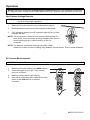
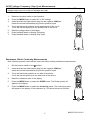
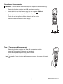
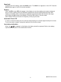
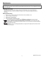
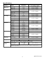
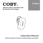
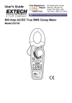
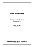
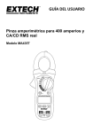
User's Guide
200Amp AC Clamp Meter + NCV
Model MA250
Introduction
Congratulations on your purchase of this Extech MA250 Clamp Meter. This meter measures AC
Current, AC/DC Voltage, Resistance, Capacitance, Frequency, Diode Test, Duty Cycle and Continuity.
Special features include Thermocouple Temperature and Non-Contact Voltage detection. The double
molded case is designed for heavy duty use. This meter is shipped fully tested and calibrated and, with
proper use, will provide years of reliable service.
Safety
International Safety Symbols
This symbol, adjacent to another symbol or terminal, indicates the user must refer
to the manual for further information.
This symbol, adjacent to a terminal, indicates that, under normal use, hazardous
voltages may be present
Double insulation
WARNING
This WARNING symbol indicates a potentially hazardous situation, which if not
avoided, could result in death or serious injury.
CAUTION
This CAUTION symbol indicates a potentially hazardous situation, which if not
avoided, may result damage to the product.
PER IEC1010 OVERVOLTAGE INSTALLATION CATEGORY
OVERVOLTAGE CATEGORY I
Equipment of OVERVOLTAGE CATEGORY I is equipment for connection to circuits in which
measures are taken to limit the transient overvoltages to an appropriate low level.
Note – Examples include protected electronic circuits.
OVERVOLTAGE CATEGORY II
Equipment of OVERVOLTAGE CATEGORY II is energy-consuming equipment to be supplied from
the fixed installation.
Note – Examples include household, office, and laboratory appliances.
OVERVOLTAGE CATEGORY III
Equipment of OVERVOLTAGE CATEGORY III is equipment in fixed installations.
Note – Examples include switches in the fixed installation and some equipment for industrial use with
permanent connection to the fixed installation.
OVERVOLTAGE CATEGORY IV
Equipment of OVERVOLTAGE CATEGORY IV is for use at the origin of the installation.
Note – Examples include electricity meters and primary over-current protection equipment
2
MA250-EU-EN-V3.2-6/11
SAFETY NOTES
•
•
•
•
Do not exceed the maximum allowable input range of any function.
Do not apply voltage to meter when resistance function is selected.
Set the function switch OFF when the meter is not in use.
Remove the battery if meter is to be stored for longer than 60 days.
WARNINGS
•
•
•
•
Set function switch to the appropriate position before measuring.
When measuring volts do not switch to current/resistance modes.
Do not measure current on a circuit whose voltage exceeds 600V.
When changing ranges always disconnect the test leads from the circuit under test.
CAUTIONS
•
•
•
•
•
•
•
Improper use of this meter can cause damage, shock, injury or death. Read and understand
this user manual before operating the meter.
Always remove the test leads before replacing the battery or fuses.
Inspect the condition of the test leads and the meter itself for any damage before operating the
meter. Repair or replace any damage before use.
Use great care when making measurements if the voltages are greater than 25VAC rms or
35VDC. These voltages are considered a shock hazard.
Always discharge capacitors and remove power from the device under test before performing
Diode, Resistance or Continuity tests.
Voltage checks on electrical outlets can be difficult and misleading because of the uncertainty
of connection to the recessed electrical contacts. Other means should be used to ensure that
the terminals are not "live".
If the equipment is used in a manner not specified by the manufacturer, the protection provided
by the equipment may be impaired.
Function
Maximum Input
A AC,
200A
V DC, V AC
600V DC/AC
Resistance, Capacitance, Frequency, Diode
Test, Continuity, Temperature
250V DC/AC
3
MA250-EU-EN-V3.2-6/11
Description
Meter Description
1.
Current clamp
2.
NCV LED indicator
3.
Clamp opening trigger
4.
MODE button
5.
HZ/% button
6.
LCD Display
7.
Negative input jack
8.
Non-Contact Voltage Detector
9.
HOLD button
1
8
2
3
4
10. Function Switch
11. Relative Button
12. Battery compartment (rear)
9
10
11
5
6
12
7
13
13. Positive input jack
Display icons Description
HOLD
AUTO
DC
AC
REL
V
Ω
A
F
Hz
%
o
o
F and C
n, m, μ, M, k
•)))
Data Hold
Autoranging
Direct Current
Alternating Current
Low battery
Relative
Volts (Voltage)
Ohms (Resistance)
Amperes (Current)
Farad (Capacitance)
Hertz (Frequency)
Duty Ratio
Fahrenheit and Celsius units (Temperature)
Unit of measure prefixes: nano, milli, micro, mega, and kilo
Continuity test
Diode test
4
MA250-EU-EN-V3.2-6/11
Operation
NOTES: Read and understand all Warning and Caution statements in this operation manual prior
to using this meter. Set the function select switch to the OFF position when the meter is not in use.
Non-Contact Voltage Detector
WARNING: Risk of Electrocution. Before use, always test the Voltage Detector on a known live
circuit to verify proper operation.
1.
Rotate the Function switch to any measurement position.
2.
Place the detector probe tip on the conductor to be tested.
3.
If AC voltage is present, the NCV detector light will turn on with
a steady red light.
NOTE: The conductors in electrical cord sets are often twisted. For
best results, move the probe tip along a length of the cord to
assure placing the tip in close proximity to the live
conductor.
NOTE: The detector is designed with high sensitivity. Static
electricity or other sources of energy may randomly trip the sensor. This is normal operation.
AC Current Measurements
WARNING: Disconnect the test leads before making clamp measurements.
1.
Rotate the Function switch to the 200A position
2.
Press the trigger to open jaw. Fully enclose
only one conductor.
3.
Read the current value in the display.
4.
If the value is less than 40A, rotate the function
switch to the 20A position to improve
resolution.
5
MA250-EU-EN-V3.2-6/11
AC/DC Voltage, Frequency, Duty Cycle Measurements
CAUTION: Do not measure voltages if a motor on the circuit is being switched ON or OFF. Large
voltage surges may occur that can damage the meter.
1.
Rotate the function switch to the V position.
2.
Press the MODE button to select AC or DC Voltage.
3.
Insert the black test lead banana plug into the negative COM jack.
Insert the red test lead banana plug into the positive V jack.
Touch the black test probe tip to the negative side of the circuit.
Touch the red test probe tip to the positive side of the circuit.
Read the voltage value in the display.
Press the Hz % button to display Frequency
Press the Hz % button to display Duty Cycle
4.
5.
6.
7.
Resistance, Diode, Continuity Measurements
Note: Remove power from the device under test before making resistance measurements
1.
Set the function switch to the Ω position.
2.
Insert the black test lead banana plug into the negative COM jack.
Insert the red test lead banana plug into the positive V jack.
3.
Touch the black test probe tip to one side of the device.
Touch the red test probe tip to the other side of the device.
4.
Read the resistance value in the display.
5.
Press the MODE button to select the DIODE mode. The Diode symbol will
appear in the display.
6.
Press the MODE button to select the Continuity mode. The continuity symbol
will appear in the display. If the resistance is <150 ohms the tone will sound.
6
MA250-EU-EN-V3.2-6/11
Capacitance Measurements
WARNING: To avoid electric shock, discharge the capacitor before measuring.
1.
Rotate the function switch to the CAP capacitance position.
2.
Insert the black test lead banana plug into the negative COM jack.
jack.
Insert the red test lead banana plug into the positive
3.
Touch the black test probe tip to one side of the device.
Touch the red test probe tip to the other side of the device.
4.
Read the capacitance value in the display.
Type K Temperature Measurements
1.
Rotate the function switch to the °F or °C temperature position.
2.
Insert the Temperature Probe into the input jacks.
3.
Place the temperature probe tip(s) where needed.
4. Read the temperature on the display.
Note: In case of an open input or a temperature overrange, the meter will display
“OL” .
7
MA250-EU-EN-V3.2-6/11
Data Hold
To freeze the LCD reading, press the HOLD button. The HOLD icon appears on the LCD. Press the
HOLD button again to return to normal operation.
Relative
Press the REL button (REL will appear in the display) to zero the reading and create a reference
point. All future reading will be the difference between the actual reading and the stored “REL”
reading. In the REL mode, autoranging is disabled and measurements are limited to the range
active when the REL button was pressed. Press the REL button to exit the mode.
Note: Relative does not function in Frequency or Duty Cycle mode.
Automatic Power Off
In order to conserve battery life, the meter will automatically turn off after approximately 30 minutes.
To turn the meter on again, change the position of the function switch.
Low battery indication
When the
icon appears in the display, the battery should be replaced. Refer to the battery
replacement procedure in the maintenance section.
8
MA250-EU-EN-V3.2-6/11
Maintenance
WARNING: To avoid electrical shock, disconnect the meter from any circuit, remove the test leads
from the input terminals, and turn OFF the meter before opening the case. Do not operate the meter
with an open case.
Cleaning and Storage
Periodically wipe the case with a damp cloth and mild detergent; do not use abrasives or
solvents. If the meter is not to be used for 60 days or more, remove the battery and store it
separately.
Battery Replacement
1.
Remove the 2 Phillips head screws that secures the rear battery cover
2.
Open the battery compartment
3.
Replace the 2 AAA batteries.
4.
Secure the battery compartment door
You, as the end user, are legally bound (EU Battery ordinance) to return all used
batteries, disposal in the household garbage is prohibited! You can hand over your
used batteries / accumulators at collection points in your community or wherever batteries
accumulators are sold!
Disposal: Follow the valid legal stipulations in respect of the disposal of the device at the
end of its lifecycle
9
MA250-EU-EN-V3.2-6/11
Specifications
0.01A
Accuracy
(% of reading + digits)
±(2.5% + 8 digits)
200.0 AAC
0.1A
±(2.8% + 8 digits)
4.000 VAC
0.001V
40.00 VAC
0.01V
400.0 VAC
0.1V
Function
Range
AC Current
20.00 AAC
50/60Hz
AC Voltage
50 to 400Hz
Resolution
600 VAC
DC Voltage
1V
±(2.5% + 8 digits)
400.0 mVDC
0.1mV
±(0.8% + 2 digits)
4.000 VDC
0.001V
40.00 VDC
0.01V
400.0 VDC
0.1V
600 VDC
Resistance
Capacitance
Frequency
±(1.8% + 8 digits)
±(1.5% + 2 digits)
1V
±(2.0% + 2 digits)
400.0Ω
0.1Ω
±(1.0% + 4 digits)
4.000kΩ
0.001kΩ
40.00kΩ
0.01kΩ
±(1.5% + 2 digits)
400.0kΩ
0.1kΩ
4.000MΩ
0.001MΩ
±(2.5% + 3 digits)
40.00MΩ
0.01MΩ
±(3.5% + 5 digits)
40.00nF
0.01nF
±(4.0% + 20 digits)
400.0nF
0.1nF
40.00µF
0.01µF
100.0µF
0.1µF
10 to 10kHz
0.01Hz
±(1.5% + 2 digits)
0.1%
±(1.2% + 2 digits)
±(3.0% + 5 digits)
Sensitivity: 15V rms
Duty Cycle
0.5% to 99.0%
Pulse width: 100μs to 100ms, Frequency: 10Hz to 10kHz
Temperature
Type K
-4.0 to 1400°F
-20 to 760°C
0.1° <400°
1° >400°
±(3% + 9°F/5°C)
Specification does not include probe accuracy. Range of supplied probe is -22
to 572°F (-30 to 300°C).
10
MA250-EU-EN-V3.2-6/11
General Specifications
Clamp jaw opening
Display
Continuity check
Diode test
Low Battery indication
Over-range indication
Measurement rate
Thermocouple sensor
Input Impedance
AC bandwidth
AC response
Operating Temperature
Storage Temperature
Operating Humidity
Storage Humidity
Operating Altitude
Battery
Auto power OFF
Dimensions & Weight
Safety
Approvals
30mm (1.18") approx.
4,000 count LCD
Threshold <150Ω; Test current < 0.5mA
Test current of 0.3mA typical;
Open circuit voltage [ 1.5VDC typical
Battery symbol is displayed
‘OL’ display
2 readings per second, nominal
Type K thermocouple required
10MΩ (VDC and VAC)
50 to 400Hz (VAC)
Average responding
5°C to 40°C (41°F to 104°F)
-20°C to 60°C (-4°F to 140°F)
Max 80% up to 31°C (87°F) decreasing linearly to 50% at 40°C
(104°F)
<80%
2000meters (7000ft) maximum.
Two “AAA” 1.5V batteries
After approx. 30 minutes
200x66x37mm (7.9x2.6x1.5”); 205g (7.23oz)
For indoor use and in accordance with the requirements for double
insulation to IEC1010-1 (2001): EN61010-1 (2001) Overvoltage
Category III 600V, Pollution Degree 2.
CE,
Copyright © 2011 Extech Instruments Corporation (a FLIR company)
All rights reserved including the right of reproduction in whole or in part in any form.
www.extech.com
11
MA250-EU-EN-V3.2-6/11