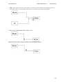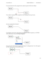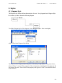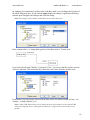
1
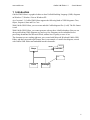
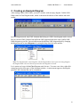
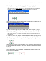
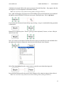
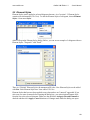
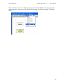
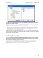
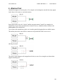
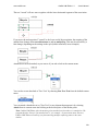
Cadifra UML Editor 1.3
Fast and Lightweight UML Diagram Editor
User's Manual
www.cadifra.com
[email protected]
Copyright © 2012 Adrian & Frank Buehlmann. All rights reserved.
Cadifra is a trademark of Adrian & Frank Buehlmann.
Microsoft, Windows 7, Windows Vista, Windows XP, Windows, Microsoft Word are trademarks or
registered trademarks of Microsoft Corporation.
UML and Unified Modeling Language are trademarks or registered trademarks of Object Management
Group Inc.
Last modified: 2012-04-12
www.cadifra.com
Cadifra UML Editor 1.3
User's Manual
1 Introduction
Cadifra UML Editor is a graphical editor to draw Unified Modeling Language (UML) diagrams
on Windows 7, Windows Vista or Windows XP.
As of version 1.3, Cadifra UML Editor supports the following kinds of UML diagrams: Class,
Object, Sequence, State and Use Case.
With Cadifra UML Editor, you can create and edit Cadifra diagram files (*.cdd). The file format
is xml.
With Cadifra UML Editor, you cannot generate code nor does it build a database. But you can
draw good looking UML diagrams easy and very fast. Diagrams can be embedded in text
processing documents like Microsoft Word, without loss of quality or ease of use.
The document you are reading right now, was created with Microsoft Word and Cadifra UML
Editor, and then converted to pdf format. Here is an example of a small class diagram, created
with Cadifra UML Editor and embedded into this document:
<Shape>
*
owner
Shape
Collection
note
Circle
Rectangle
1
www.cadifra.com
Cadifra UML Editor 1.3
User's Manual
2 Creating an Example Diagram
After starting Cadifra UML Editor, you have a window with an empty diagram. Cadifra UML
Editor starts in Class Diagram mode, which is shown on the title bar of the window and in the
toolbar.
In Class Diagram mode, only UML elements that belong to a UML class diagram can be created,
but you can mix UML elements from different UML diagram kinds in the same Cadifra UML
Editor diagram as you like. Just switch between the different UML diagram kinds by changing
the diagram mode in menu Diagram or by using the drop down list in the toolbar.
Note: The diagram mode is saved together with the diagram data. If you open an existing diagram,
the diagram mode is the one that was present when the diagram was saved.
Let’s assume we keep with the Class Diagram mode for now. To create a new class, right-click
somewhere in the white space of the document window. A context menu appears, showing the
possible UML elements that can be created here:
2
www.cadifra.com
Cadifra UML Editor 1.3
User's Manual
Select New Class from the menu. The class is placed nearby to the point where the context menu
was opened. Now you should have your first UML element in Cadifra UML Editor:
Note: Bold text marks the default command. Every context menu saves the chosen command as the
new default. As an easy shortcut, you can call the default command with ctrl+right-click.
Note the star appearing after the name of the diagram (“Diagram1.cdd”) in the title bar. The star
appears whenever the diagram needs to be saved.
If you undo the creation of the class (ctrl+z or Edit > Undo), the star disappears. If you redo
(ctrl+y), it reappears again. By the way: you can always undo/redo any number of steps. There is
no limit in the number of steps that can be undone. Undo/redo is also available in the toolbar.
Note: The undo stack is not saved with the diagram. The undo stack is always discarded when you
close a diagram.
So, we still have our new class. The newly created (or undone and redone) class is selected. If a
single element with a text is selected, you can start typing its name on the keyboard. The name is
replaced by the text you enter. No need to double click. No ugly dialog box to fight with. So, let’s
say we enter “Bicycle” as the new name of the class:
Note the dashed red box inside the class box and the flashing text insertion cursor. You can leave
the text editing mode of the class name by left-clicking somewhere in the white space or hitting
the ESC key.
Note: You can also switch to text edit mode by double-clicking on a text.
Now let’s drag the newly created class around. Just hold down the left mouse button over the
Bicycle class and move the mouse.
3
www.cadifra.com
Cadifra UML Editor 1.3
User's Manual
A dashed red rectangle follows the mouse movement. Note the faint lines – they appear when the
moving box is in exact alignment with another element).
Note: You can always escape from the moving mode by hitting the ESC key.
Now, while still dragging (moving mouse while holding left mouse button down) press and hold
the ctrl key on the keyboard. The mouse cursor gets a small plus sign – this is copy move.
If you release the left mouse button during copy moving, a copy is created and the drag operation
is terminated.
Rename the second Bicycle to “Person” (just type on the keyboard). So now, we have a Bicycle
and a Person class.
Now, let's create an association. Position the mouse cursor over the Bicycle class and hold down
the right mouse button to display the context menu of the Bicycle class element.
Select New Association from the context menu to enter the association drawing mode.
In association drawing mode, the mouse cursor changes to the connector sign (as shown above).
Note: You can always escape from the association drawing mode by hitting the ESC key.
4
www.cadifra.com
Cadifra UML Editor 1.3
User's Manual
Move the mouse and see how a dashed red line follows your mouse movement from the box of
the Bicycle class. Now, position the mouse cursor over the Person class. Note how the mouse
curser gets bold when it's over the Person class. This is a hint that the association can snap to the
Person class.
While the mouse cursor looks bold, click the left mouse button to finish the creation of the
association. Now, you should have a new association as shown below.
Note that the newly created association is selected with small green squares at its ends.
Now, let's add a role to the Bicycle side of the association. To do this, position the mouse cursor
over the Bicycle end of the association
and click the right mouse button to display the context menu of the association end.
Select New Role from the context menu
and enter the text "vehicle".
You can move the vehicle text around by dragging it. While doing this, a dashed red line is drawn
to the end of the association, to show where it belongs to.
5
www.cadifra.com
Cadifra UML Editor 1.3
User's Manual
This was a first little tour on using Cadifra UML Editor. We recommend experimenting yourself
with Cadifra UML Editor to explore other features or read on in the following chapters.
6
www.cadifra.com
Cadifra UML Editor 1.3
User's Manual
3 Resizing
3.1 Single Element Resizing
UML elements can be resized by dragging one of their resize controls (they appear when the
element it is selected). Position the mouse cursor over one of the controls and press down the left
mouse button while moving the mouse
Note: You can always escape from the resizing mode by hitting the ESC key.
Release the mouse button when the red dashed line has the requested size of the element.
3.2 Multi Element Resizing
Cadifra UML Editor supports multi-element resizing. Select the elements that you wish to resize
and do the resize on one of the elements.
All other selected elements of the same type follow that resizing.
7
www.cadifra.com
Cadifra UML Editor 1.3
User's Manual
4 Connectors
4.1 Creating Connectors with Multiple Segments
Let's assume we wanted to draw the following class diagram with an association consisting of
three segments:
Bicycle
Person
We will use the term join to denote the point where two segment ends of a connector coincide.
The above association has two joins.
The start situation is this:
Bicycle
Person
To create the association, select New Association from the context menu of the bicycle class.
You are then in connector drawing mode, where a dashed red line follows the position of the
mouse cursor.
Note: You can always escape from the connector drawing mode by hitting the ESC key.
Move the mouse to the right and click with the left mouse button at the position of the upper join
and move the mouse a bit downwards.
The position of the start of the association at the Bicycle class is now fixed and you have one
join. The horizontal position of the newly created join is not yet fixed. See how the vertical
segment of the dashed red line and the new join follow your horizontal mouse movements.
8
www.cadifra.com
Cadifra UML Editor 1.3
User's Manual
To fix the horizontal position of the new upper join, click again with the left mouse button and
move the mouse a bit to the right.
The vertical position of the new lower join is not yet fixed – the lower horizontal segment still
follows your vertical mouse movements.
Finally, position the mouse cursor over the Person class, until the mouse cursor gets bold.
Now, click the left mouse button to fix the end of the association. This ends the connector
drawing mode and you should have completed the new association.
9
www.cadifra.com
Cadifra UML Editor 1.3
User's Manual
4.2 Creating Connectors with Oblique Segments
Let's assume we wanted to draw the following class diagram with an association consisting of
two segments, one of them being oblique:
Bicycle
Person
To draw this kind of association, use the instructions from the previous chapter up until you are
in the following state (New Association starting from class Bicycle, and two mouse clicks):
When you are in the situation shown above, hold down the ctrl key on the keyboard. The last two
orthogonal segments will then be replaced by an oblique segment that follows your mouse
movements.
Note: ctrl toggles between orthogonal and oblique connector drawing mode.
While still holding down the ctrl key, move the mouse cursor over the person class,
and then click the left mouse button to complete the association.
The default mode for drawing associations in class diagrams is orthogonal (oblique with ctrl key
down).
For note connectors and use case associations, the default is oblique (orthogonal with ctrl key
down).
10
www.cadifra.com
Cadifra UML Editor 1.3
User's Manual
4.3 Moving and Shaping Connectors
Orthogonal segments can be moved by dragging them with the mouse.
Position the mouse cursor over a segment (make sure nothing is selected):
and then hold down the left mouse button while moving the mouse.
Additional segments are automatically added as needed.
If you move the Bicycle class, its directly attached segment follows the movement of the class.
11
www.cadifra.com
Cadifra UML Editor 1.3
User's Manual
Select the terminals at all ends of a connector to move all segments of the connector together with
the terminals.
In our example, select the Bicycle class and the Person class (hold down a shift key and left-click
the Person class to extend the selection) and then move the Bicycle class:
To move an end, position the mouse cursor over it
and then hold down the left mouse button while moving the mouse.
You can detach connectors or reattach them to other terminals.
Detached ends are marked with a red diamond when their segment is selected. This helps finding
detached ends.
12
www.cadifra.com
Cadifra UML Editor 1.3
User's Manual
Hint: if two ends are too close to each other to catch one of them, make sure the segment of the end
you whish to move is selected. This will increase its sensitivity to get caught by the mouse.
To move a join, position the mouse cursor over it
and then hold down the left mouse button while moving the mouse.
13
www.cadifra.com
Cadifra UML Editor 1.3
User's Manual
If you press down the ctrl key (toggle mode), adjacent segments will become oblique:
If two adjacent segments form a straight line when finishing ctrl-moving of a join,
the join is automatically eliminated:
If you happen to look at the context menu of an orthogonal connector segment, you will find a
check-marked menu entry named Keep Orthogonal.
If you remove the check-mark, the segment will "forget" its orthogonal state. You will recognize
the effect, when you move the attached terminal:
14
www.cadifra.com
Cadifra UML Editor 1.3
User's Manual
4.4 Creating Connectors in Tree Form
To create a connector in tree form,
simply attach a new connector
to an existing one.
Note: Not every kind of connector supports tree form. If the mouse cursor does not get bold when
you try attaching a connector to another one, then that connector kind may not support tree form.
15
www.cadifra.com
Cadifra UML Editor 1.3
User's Manual
5 Styles
5.1 Diagram Style
The Diagram style defines the font characteristics for texts. Every diagram has its Diagram Style.
Let's assume you have drawn the following diagram
To edit the Diagram Style of this diagram, choose Diagram Style... from menu Styles,
which will open the Diagram Style dialog
The left pane of the Diagram Style dialog shows a hierarchy of style nodes. In the picture above,
the node "Base" is selected. The properties of the selected node are displayed in the right pane. In
our example, the node "Base" has the Font property with Typeface "Arial", Size and Bold values
as shown above.
16
www.cadifra.com
Cadifra UML Editor 1.3
User's Manual
By changing for example the Typeface value of the Base node, you can change the Typeface of
the whole diagram at once. If you click the Apply button, the change is applied but the dialog
remains open. Ok applies the changes and closes the dialog.
Note: Style changes can be undone without limits as any other edit action.
In the example above, we changed the typeface of the Base node to "Courier New".
If you select the sub-node "Header" of sub-node "Class", you can see that the typeface and size
values are inherited. This means that they inherit their real values from the ancestor node.
In sub-nodes, you can override values from ancestor nodes. Per default, Header of Class – for
example – overrides Bold to "yes".
Note: Cadifra UML Editor allows you to change the fonts of all instances of each kind of UML
element of a diagram at once. Setting font overrides for a single instance of an element is not
possible.
17
www.cadifra.com
Cadifra UML Editor 1.3
User's Manual
5.2 Element Styles
Element Styles can be applied to selected diagram elements. As of version 1.3, Element Styles
contain color information (Fill Color). To edit the Element Styles of a diagram, choose Element
Styles... from menu Styles
which will open the Element Styles dialog. Below, you can see an example of a diagram with two
Element Styles: "Proposal 1" and "Draft"
There is a "Default" Element Style with transparent fill color. New Element Styles can be added
with New. Each Element Style has a Name and a Fill Color.
Element Styles that have not been applied to any element have an "(unused)" appended. If you
select one ore more elements before opening the dialog box, you can assign an Element Style
from the list to the selected elements. Make sure the checkbox Assign to selected Elements is
checked and then click Apply. Cancel dismisses all changes made while the dialog was open.
18
www.cadifra.com
Cadifra UML Editor 1.3
User's Manual
The first 30 Element Styles of a diagram appear at the end of the Styles menu, from where they
can be applied to a selection (use the Element Styles dialog if you have more than 30 Element
Styles).
19
www.cadifra.com
Cadifra UML Editor 1.3
User's Manual
5.3 Diagrams and Diagram Styles
Each diagram has exactly one Diagram Style. Cadifra UML Editor 1.3 does not support multiple
Diagram Styles in the same diagram. Of course, two diagrams can have differing Diagram Styles.
If you copy diagram parts from one diagram to another (by copy/paste or a drag and drop action),
the Diagram Styles are treated as follows: If the Diagram Style in the destination diagram differs
from Diagram Style in the source diagram, the appearance of the pasted elements is automatically adjusted to use the Diagram Style of the same kinds of elements in the target diagram.
Note: When copying UML elements, the appearance of pasted elements is changed to conform to all
existing nodes in the Diagram Style of the target diagram. If transferred elements use nodes that do
not exist in the Diagram Style of the target diagram, the missing nodes are added to the Diagram
Style of the target diagram.
If you have a diagram, that contains your preferred Diagram Style, you can import the Diagram
Style of this "preferred style diagram" into any other diagram. To do this, open the destination
diagram and select Import... from menu Styles, which will bring up a file open dialog to select
the source file for the transfer.
Note: When importing a Diagram Style, the source Diagram Style will be merged into the target
Diagram Style by replacing existing style nodes in the target diagram with corresponding nodes
from the source diagram. Nodes in the target Diagram Style that do not have corresponding nodes
in the source Diagram Style remain unchanged.
5.4 Used and Unused Style Nodes
Let's assume you have drawn the following diagram
which contains both class and state diagram parts. Then, further assume, you deleted the class
diagram parts, such that the diagram now looks like this:
If you now open the style editor, it looks like this:
20
www.cadifra.com
Cadifra UML Editor 1.3
User's Manual
Now, there are style nodes marked as unused. This happens because style nodes are not deleted
when you delete diagram elements.
To delete the "unused" style nodes, mark Delete unused in the Diagram Style dialog and click
the OO button (Clicking "Apply" does not delete unused nodes).
Note: There may be style nodes that are not marked as "unused" in the Style dialog, even though no
corresponding element exists in the diagram at all ("Free Text" in the example above). This is
intentional. The term "unused" is not used strictly here.
On the other hand, if you start with a blank diagram, style nodes are added as needed when you
create new elements. Note that those automatically added style nodes get default values which are
hard wired into Cadifra UML Editor.
5.5 Creating Template Diagrams
Cadifra UML Editor does not directly support diagram templates. However, you may create one
or more template diagrams by creating normal diagrams containing exemplary UML elements
that you usually use and adjust their style as you like.
If you always copy a template diagram when starting a new diagram, your newly created
elements will use your default style as you defined in your template diagram. Each of your
template diagrams may also be used as the source of a style import.
21
www.cadifra.com
Cadifra UML Editor 1.3
User's Manual
6 Attached Text
Attached text appears at various places. For example, in class diagrams, attached text may appear
in the form of role names or association names.
In the picture above, the role "vehicle" and the association name "owned" are examples for
attached text. If you select an attached text ("owned" above), a dashed red line is drawn to the
anchor point of the attached text.
You can move the attached text relative to its anchor point by dragging the text with the mouse.
The anchor point can be moved like a connector end: position the mouse cursor over it
and drag it around.
The mouse cursor changes to the snapped mode when you are close enough to an element that
supports attaching text.
22
www.cadifra.com
Cadifra UML Editor 1.3
User's Manual
The text "owned" will now move together with the lower horizontal segment of the association.
If you move the anchor point of "owned" to the lower end of the association, the meaning of the
attached text changes from association name to role or multiplicity. This may be reflected by a
font change, depending on the settings in the style (bold to non-bold, in our example).
Attached text can be detached, as you can see if you take a look at the context menu.
You can also create detached or "Free Text" by choosing New Free Text from the default context
menu.
You can attach a detached text (or "Free Text") to any element that supports it by selecting
Attach from its context menu and clicking at the desired place of the anchor point.
Note: Cadifra UML Editor infers the meaning of an attached text from where it is attached to. The
program therefore "knows" if an attached text is – for example – an association name. However,
Cadifra UML Editor will not keep you from attaching multiple conflicting names to the same
element.
23
www.cadifra.com
Cadifra UML Editor 1.3
User's Manual
7 Zoom and Scrolling
7.1 Zoom with the Mouse Wheel (ctrl+wheel)
If you have a mouse with a wheel, you can use the wheel to zoom in and out.
Hold down the ctrl key on the keyboard and turn the mouse wheel forward to zoom in.
Turn the wheel backward to zoom out.
Note: The point on the diagram at the mouse cursor keeps its position on the screen during mousewheel zooming.
7.2 Zoom with Mouse Clicks (ctrl+shift, left/right click)
Hold down ctrl+shift on the keyboard and click with the left mouse button to zoom in.
Click the right mouse button to zoom out.
Note: The point on the diagram at the mouse cursor keeps its position on the screen on mouse-click
zooming.
7.3 Zoom to Area (ctrl+shift, left drag)
To zoom to an area, hold down ctrl+shift on the keyboard, press down the left mouse button and
move the mouse.
A dashed red rectangle follows your mouse movement.
The view will be zoomed to the marked area as soon as you release the mouse button.
7.4 Scrolling with the Mouse Wheel (wheel/shift+wheel)
If you have a mouse with a wheel, turn the wheel to scroll up and down.
Hold down shift on the keyboard and turn the mouse wheel to scroll left and right
Note: If the window (or a split window) does not scroll or the wrong window scrolls, click with the
left mouse button somewhere inside the window you want to scroll.
7.5 Scrolling in any Direction (ctrl+shift, right drag)
Instead of using the horizontal and vertical scroll bars, you can move the visible area of the
diagram in any direction.
Hold down ctrl+shift on the keyboard and hold down the right mouse button. Now, move the
mouse: the mouse cursor changes to a hand symbol and the diagram follows your mouse
movement.
24