1
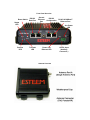
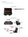
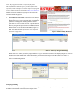
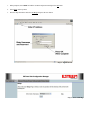
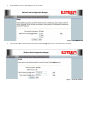
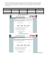
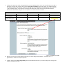
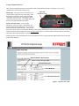
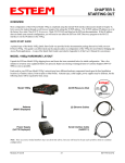
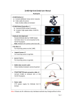
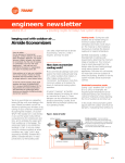
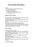
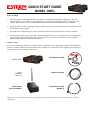
QUICK START GUIDE
MODEL 195Es
Before You Begin
•
The ESTeem Model 195Es wireless Ethernet radio modem is compatible with many different applications. The most
common application is to bridge two or more Ethernet devices. This guide will demonstrate the basic configuration and
testing of a pair of 195Es’s. For more detailed information, please see the ESTeem Model 195Es User’s Manual.
•
This guide assumes you have a working knowledge of Ethernet networking, TCP/IP protocol and how to identify and set the
TCP/IP address on your computer.
•
The 195Es can be configured using any current web browser software such as Internet Explorer, Netscape or Mozilla.
•
The following procedure will provide an initial communication link between two or more Model 195’s for testing purposes.
All the example commands listed in this guide can be adjusted to fit your communication network. Please consult the
ESTeem Model 195Es User’s Manual for more details.
Unpack Contents
Each node in your ESTeem Model 195Es’s network may have different hardware components based upon the final installation
location (i.e Outdoor, Indoor, Point-to-point or Muti-Point). Antenna types, cable lengths, power supplies may be different, but
the following items will be required for basic setup:
Model 195Es
AA109 Resource Disk
Antenna
(AA20DMEs
Displayed)
(2) Ethernet Cables
Power Supply
(AA175 Displayed)
Serial Interface Cable
(AA6021.1)
Note: Your accessory model numbers may vary from the above, but you will need to locate each of above items to continue
configuration.
Front Panel Overview
RS-232
Reset Switch Data Port
Status
LED
Receive
LED
Transmit
LED
Second
Ethernet
Port
RS-232
Configuration
RJ-45 10/100BaseT
Ethernet Port
Aux Power
LED
Power over
Ethernet LED
Antenna Overview
12 VDC Input
(Auxiliary
Connector )
Begin Programming
1.
Assemble the ESTeem Model 195Es using the following:
Antenna Connections
Power and Data Connection
2.
The Model 195Es will link to other Model 195Es’s on the network via the WLAN Media Access Control (MAC) address
found on the bottom of the case. This MAC address is six hexadecimal digits separated by colons and is configured at the
factory. Every MAC address in the world is unique and can not be changed. Complete the following chart to aid in your
configuration:
Name
Example Modem 1
Serial Number
E-14001
IP Address
172.16.8.101
Ethernet MAC
00:04:3f:00:01:01
WLAN MAC
00:04:3f:00:01:02
3.
Configuration of the Model 195Es is completed through the product’s internal web server. To access this configuration page,
you will need to enter the 195Es’s IP address in your web browser. The IP address set at the factory is Class B (i.e.
172.16.x.x) address and is printed on the Quality Assurance sheet sent with each 195Es. If the factory default address
matches your network configuration, please proceed to Using Setup, otherwise continue to step 4.
4.
Install the ESTeem Discovery Utility. The ESTeem Discovery Utility will allow you to configure the IP address on the
Model 195Es to match your network. Install the Discovery Utility on your computer by inserting the Resource Disk in your
CD drive.
Note: The ESTeem Resource Disk is stand-alone copy of the ESTeem Web site (Figure 1). Navigation of the Resource Disk is
as simple as using your web browser. All technical documentation, User’s Manuals and the ESTeem Utility Program is
available on the disk.
Place the ESTeem Utility CD in your CD-ROM drive. The CD will auto load the ESTeem main page
Note: If the page does not auto load, open your web browser and set your address line to D:\index.html (Where D: is the
drive letter for your CD-ROM drive).
From the Main Page select Support>ESTeem Utilities and click on ESTeem Discovery Utility.
Figure 1 –ESTeem Resource Disk Main Page
Note: This program is saved in a compressed file format.
Microsoft Windows XP® will open the file directly, but other
operating systems will require a common compression program
such as WinZip available for download at http://www.winzip.com
Double click on the 195EdiscoverySetup.exe file listed in the
window to install the program.
5.
Set IP Address on the 195Es. Connect the Model 195Es to
your computer either direct to the Ethernet card or through a
HUB/Switch using a CAT-5e Ethernet cable. The Ethernet
port on the 195Es supports Auto-Negotiation so either a
patch cable or crossover cable will work. Open the ESTeem
Discovery Program and press the Discover Modems button.
The Model 195Es will be displayed in the program by the
Ethernet MAC address and Current IP Address (Figure 3).
Note: The SSID and Mode of Operation will be adjusted
later in the configuration.
Figure 2- ESTeem Utility Download
Figure 3 – Discovery Program Main Page
Double-click on the 195Es you wish to program and the Configure IP Address window will be displayed (Figure 4). Enter an
IP address and Subnet Mask for the 195Es that matches your network subnet and press the OK button to save this to the
ESTeem. You will receive notification that the Configuration was Successful and the 195Es will reboot. Proceed to ESTeem
Setup to continue configuration.
Figure 4 – Change IP Address Window
Setup Programming
You should now be ready to configure the Model 195Es through your web browser. Open the web browser program and enter the
IP address of the ESTeem in the address line and press enter.
1.
When prompted, enter admin for both the username and password and press the OK button.
2.
Select Setup on the top menu.
3.
Press the drop-down menu and select AP Bridge and press the Next button.
Step 1 – Sign-In Screen
Step 3 – Select AP Bridge
4.
Set the DHCP services to OFF and press the Next button.
Step 4 – Turn DHCP Off
5.
Verify the IP address and netmask for the 195Es (listed as bridge device) are correct press the Next button.
Step 5 – Verify IP Address
6.
Enter in the Gateway address in the default route IP address block and any DNS information for the server. If this is not
know or on a network without a Gateway, leave these items at factory default.
Step 6 – Enter Gateway Address
7.
All 195Es modems in the network must be have the exact same Service Set Identification (SSID). The default SSID is
ESTeem and we will use this for demonstration. Enter the SSID as listed above and turn off the wireless security features by
selecting the NO radial. Press the Next button to continue.
Step 7 – Enter SSID
Note: It is recommended that security be used in all wireless applications. This procedure will forgo the security configuration
for brevity. Please see the example applications and the security appendix for further information.
8.
The next step is the configuration of the Frequency Hopping Timing Master. In the first modem, set Network Timing Master
to Yes and leave the “Upstream Timing Master” at 00:00:00:00:00:00. In the second modem, set the Network Timing Master
to No and set the “Upstream Timing Master” to the WLANC MAC address of the Timing Master (00:04:3f:00:01:02 in the
following example).
Name
Timing Master
Serial Number
E-14096
Example Addresses
IP Address
172.16.48.189
Ethernet MAC
00:04:3f:00:01:01
WLAN MAC
00:04:3f:00:01:02
Opposite 195Es We Will
Create Wireless Link
E-14034
172.16.38.114
00:04:3F:00:0B:00
00:04:3F:00:11:02
Example E-14096 Configuration
Example E-14034 Configuration
Step 8 – Setting Timing Master
9.
Configure the repeater peer list by selecting Enable the repeater capability radial to YES. Press the Add button to the right of
the repeater peer table and, using the chart created in the Begin Programming section of this guide, enter the Wireless MAC
(WLAN MAC) address of the opposite 195Es (the 195Es this unit you are programming will communicate with) in the Peer 1
– MAC Addr field (right). Leave the Path Cost settings at the default value, select None for encryption and change the
Enable Link radial to Enable and press the Create Repeater Peer button. Press the Next button.
Name
195Es We Are
Programming
Opposite 195Es We Will
Create Wireless Link
Serial Number
E-14096
Example Addresses
IP Address
172.16.48.189
Ethernet MAC
00:04:3f:00:01:01
WLAN MAC
00:04:3f:00:01:02
E-14034
172.16.38.114
00:04:3F:00:0B:00
00:04:3F:00:11:02
Step 9 – Configure Peer Table
10. Press the Commit Changes button and the modem will save all the changes made and reboot. The reboot time is
approximately 1 minute to be ready for operation.
11. Complete all steps in this Setup Programming section for the other Model 195Es’s you will be testing before moving on the
Testing Communication section.
Testing Communication Link
After you have configured at least two of the Model 195Es wireless Ethernet modems for operation, you can verify
communication with each the following steps:
Status Light – The quickest source of link status is to
view the Status Light on the face of the 195Es. If the
Status light is solid on the remote 195Es, the Model
195Es has a connection to the Timing Master Model
195Es listed in the Peer Table. The Timing Master will
have the status light illuminated at all times.
Status LED
Solid Red on Link
Status Screen/Peer Table – To view further
information on the status of the communication link
(signal strength and last update time) you can open the
Status Screen from the Web Interface. After press the
Status tab at the top of the screen the Status: Summary will be displayed showing the status of all ports and memory in the 195Es.
Under the Wireless Status heading click on the View Peer Table (Figure 5). The Peer Table will list all 195Es in client mode
connected to this modem and how it is classified.
Find the opposite 195Es in the Repeater Peers list and information such as signal strength (in dBm) and time/speed of last data
packet will be displayed.
Opposite Modem’s Wireless MAC
Receive Signal Strength (dBm)
Last Packet Received
Peer Modem ID
Other Access Points
Figure 5 – Repeater Peer Table
Ping Testing – The easiest method for testing the efficiency of data flow between the ESTeems is to conduct a Ping test to the
opposite modem’s IP address. This will test all links in the Ethernet bridge.
Technical Support
User’s Manual and Technical Documentation
http://www.esteem.com
E-Mail Support
[email protected]
Phone Support (8AM to 5PM PST Monday-Friday)
509-735-9092