1
Table of Contents
INTRODUCTION
WHAT IS OBD? ....................................................................................
1
YOU CAN DO IT! ...........................................................................................
2
SAFETY PRECAUTIONS
SAFETY FIRST! ...................................................................................
3
ABOUT THE SCAN TOOL
VEHICLES COVERED .........................................................................
BATTERY REPLACEMENT .................................................................
5
6
SCAN TOOL CONTROLS
CONTROLS AND INDICATORS ..........................................................
DISPLAY FUNCTIONS ........................................................................
8
9
ONBOARD DIAGNOSTICS
COMPUTER ENGINE CONTROLS .....................................................
DIAGNOSTIC TROUBLE CODES (DTCs) ............................................
OBD2 MONITORS ...............................................................................
12
17
20
PREPARATION FOR TESTING
PRELIMINARY VEHICLE DIAGNOSTIC WORKSHEET.......................
BEFORE YOU BEGIN ..........................................................................
VEHICLE SERVICE MANUALS ...........................................................
29
32
33
USING THE SCAN TOOL
CODE RETRIEVAL PROCEDURE ......................................................
THE ENHANCED MENU.......................................................................
VIEWING ENHANCED DTCs................................................................
VIEWING ABS DTCs ...........................................................................
ERASING DIAGNOSTIC TROUBLE CODES (DTCs) ..........................
I/M READINESS TESTING ..................................................................
34
41
42
50
54
56
LIVE DATA MODE
VIEWING LIVE DATA............................................................................
CUSTOMIZING LIVE DATA (PIDs) ......................................................
RECORDING (CAPTURING) LIVE DATA ............................................
LIVE DATA PLAYBACK ........................................................................
61
62
63
67
ADDITIONAL TESTS
SPECIAL TEST MENU .........................................................................
VIEWING VEHICLE INFORMATION ....................................................
ADJUSTMENTS AND SETTINGS .......................................................
70
74
77
USING SCAN TOOL MEMORY
VIEWING DATA IN MEMORY ..............................................................
84
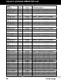
GENERIC (GLOBAL) OBD2 PID LIST ..........................................................
86
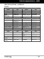
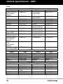
VEHICLE APPLICATIONS - ABS
ABS APPLICATIONS – DOMESTIC ....................................................
ABS APPLICATIONS – IMPORT .........................................................
91
94
GLOSSARY
GLOSSARY OF TERMS AND ABBREVIATIONS.................................
96
WARRANTY AND SERVICING
LIMITED ONE YEAR WARRANTY ...................................................... 101
SERVICE PROCEDURES ............................................................ 101
i
FixAssist™
Introduction
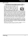
WHAT IS OBD?
WHAT IS OBD?
The FixAssist Scan Tool is designed to work on all OBD2
compliant vehicles. All 1996 and newer vehicles (cars, light trucks
and SUVs) sold in the United States are OBD2 compliant.
One of the most exciting improvements in the
automobile industry was the addition of onboard diagnostics (OBD) on vehicles, or in more
basic terms, the computer that activates the
vehicle’s “CHECK ENGINE” light. OBD1 was
designed to monitor manufacturer-specific
systems on vehicles built from 1981 to 1995.
Then came the development of OBD2, which is
on all 1996 cars and light trucks sold in the U.S. Like its predecessor,
OBD2 was adopted as part of a government mandate to lower vehicle
emissions. But what makes OBD2 unique is its universal application for
all late model cars and trucks - domestic and import. This sophisticated
program in the vehicle’s main computer system is designed to detect
failures in a range of systems, and can be accessed through a universal
OBD2 port, which is usually found under the dashboard. For all OBD
systems, if a problem is found, the computer turns on the “CHECK
ENGINE” light to warn the driver, and sets a Diagnostic Trouble Code
(DTC) to identify where the problem occurred. A special diagnostic tool,
such as the FixAssist Scan Tool, is required to retrieve these codes,
which consumers and professionals use as a starting point for repairs.
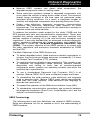
The FixAssist Scan Tool includes a "solutions database" (Fix Assist)
with recommended inspection and repair procedures for most DTCs.
The Scan Tool also provides the additional ability to retrieve enhanced
DTCs from most Chrysler/Jeep, Ford/Mazda, GM/Isuzu, Honda/Acura
and Toyota/Lexus vehicles, as well as Anti-Lock Brake System (ABS)
DTCs and vehicle information. The types of enhanced data available
depends on the vehicle make.
Additionally, the FixAssist Scan Tool includes a database containing
recommended inspection and repair actions for most DTCs.
FixAssist™
1
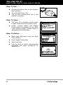
You Can Do It!
EASY TO USE - EASY TO VIEW - EASY TO DEFINE
Easy To Use . . . .
Connect the Scan Tool to the vehicle’s
test connector.
Turn the ignition key "On.”
The tool will automatically link to the
vehicle’s computer.
Easy To View . . . .
The Scan Tool retrieves stored codes,
Freeze Frame data and system status.
Codes, system status and Freeze
Frame data are displayed on the Scan
Tool’s display screen. System status is
indicated by LED indicators.
Easy To Define . . . .
2
Read code definitions from the Scan
Tool’s display.
View Freeze Frame data.
View Live Data.
Use Fix Assist to obtain recommended
inspection and repair procedures for
most DTCs.
FixAssist™
Safety Precautions
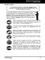
SAFETY FIRST!
SAFETY FIRST!
To avoid personal injury, instrument damage and/or
damage to your vehicle; do not use the OBD2 Scan Tool
before reading this manual.
This manual describes common test procedures used
by experienced service technicians. Many test procedures
require precautions to avoid accidents that can result in
personal injury, and/or damage to your vehicle or test
equipment. Always read your vehicle's service manual and
follow its safety precautions before and during any test or
service procedure. ALWAYS observe the following general
safety precautions:
When an engine is running, it produces carbon monoxide,
a toxic and poisonous gas. To prevent serious injury or
death from carbon monoxide poisoning, operate the
vehicle ONLY in a well-ventilated area.
To protect your eyes from propelled objects as well as hot
or caustic liquids, always wear approved safety eye
protection.
When an engine is running, many parts (such as the
coolant fan, pulleys, fan belt etc.) turn at high speed. To
avoid serious injury, always be aware of moving parts.
Keep a safe distance from these parts as well as other
potentially moving objects.
Engine parts become very hot when the engine is running.
To prevent severe burns, avoid contact with hot engine
parts.
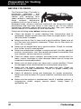
P RND L
Before starting an engine for testing or troubleshooting,
make sure the parking brake is engaged. Put the
transmission in park (for automatic transmission) or
neutral (for manual transmission). Block the drive wheels
with suitable blocks.
Connecting or disconnecting test equipment when the
ignition is ON can damage test equipment and the
vehicle's electronic components. Turn the ignition OFF
before connecting the Scan Tool to or disconnecting the
Scan Tool from the vehicle’s Data Link Connector (DLC).
FixAssist™
3
Safety Precautions
SAFETY FIRST!
To prevent damage to the on-board computer when taking
vehicle electrical measurements, always use a digital
multimeter with at least 10 MegOhms of impedance.
Fuel and battery vapors are highly flammable. To prevent
an explosion, keep all sparks, heated items and open
flames away from the battery and fuel / fuel vapors. DO
NOT SMOKE NEAR THE VEHICLE DURING TESTING.
Don't wear loose clothing or jewelry when working on an
engine. Loose clothing can become caught in the fan,
pulleys, belts, etc. Jewelry is highly conductive, and can
cause a severe burn if it makes contact between a power
source and ground.
4
FixAssist™
About the Scan Tool
VEHICLES COVERED
VEHICLES COVERED
The FixAssist Scan Tool is designed to work on all OBD2 compliant
vehicles. All 1996 and newer vehicles (cars and light trucks) sold in the
United States are OBD2 compliant.
Federal law requires that all 1996 and newer cars and light
trucks sold in the United States must be OBD2 compliant; this
includes all Domestic, Asian and European vehicles.
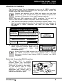
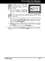
Some 1994 and 1995 vehicles are OBD2 compliant. To find out if a
1994 or 1995 vehicle is OBD2 compliant, check the following:
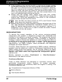
1. The Vehicle Emissions Control Information (VECI) Label. This
label is located under the hood or by the radiator of most vehicles. If
the vehicle is OBD2 compliant, the label will state “OBD II
Certified.”
VEHICLE EMISSION CONTROL INFORMATION
ENGINE FAMILY
DISPLACEMENT
VEHICLE
MANUFACTURER
EFN2.6YBT2BA
2.6L
OBD II
CERTIFIED
THIS VEHICLE CONFORMS TO U.S. EPA AND STATE
OF CALIFORNIA REGULATIONS APPLICABLE TO
1999 MODEL YEAR NEW TLEV PASSENGER CARS.
REFER TO SERVICE MANUAL FOR ADDITIONAL INFORMATION
TUNE-UP CONDITIONS: NORMAL OPERATING ENGINE TEMPERATURE,
ACCESSORIES OFF, COOLING FAN OFF, TRANSMISSION IN NEUTRAL
EXHAUST EMISSIONS STANDARDS
CERTIFICATION
IN-USE
SPARK PLUG
TYPE NGK BPRE-11
GAP: 1.1MM
OBD II
CERTIFIED
STANDARD CATEGORY
TLEV
TLEV INTERMEDIATE
CATALYST
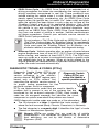
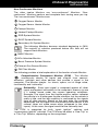
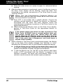
2. Government Regulations require that all
OBD2 compliant vehicles must have a
“common”
sixteen-pin
Data
Link
Connector (DLC).
1 2 3 4 5 6 7 8
9 10111213141516
Some 1994 and 1995 vehicles have 16-pin connectors but are
not OBD2 compliant. Only those vehicles with a Vehicle
Emissions Control Label stating “OBD II Certified” are OBD2
compliant.
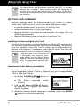
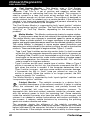
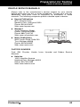
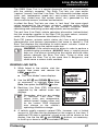
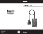
Data Link Connector (DLC) Location
The 16-pin DLC is usually
located under the instrument
panel (dash), within 12 inches
(300 mm) of center of the panel,
on the driver’s side of most
vehicles. It should be easily
accessible and visible from a
kneeling position outside the
vehicle with the door open.
FixAssist™
LEFT CORNER
OF DASH
NEAR
CENTER
OF DASH
BEHIND
ASHTRAY
5
About the Scan Tool
BATTERY REPLACEMENT
On some Asian and European vehicles the DLC is located
behind the “ashtray” (the ashtray must be removed to
access it) or on the far left corner of the dash. If the DLC
cannot be located, consult the vehicle’s service manual for
the location.
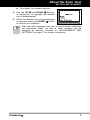
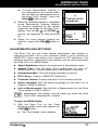
BATTERY REPLACEMENT
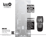
Replace batteries when the battery symbol
is visible on display
and/or the 3 LEDS are all lit and no other data is visible on screen.
1. Locate the battery cover on the back of the Scan Tool.
2. Slide the battery cover off (use your fingers).
3. Replace batteries with three AA-size batteries (for longer life, use
Alkaline-type batteries).
4. Reinstall the battery cover on the back of the Scan Tool.
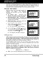
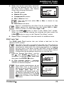
Installing the Secure Digital (SD) Card
The Scan Tool includes a pre-installed Secure Digital (SD) memory card
that contains code definitions and the FixAssist database. The SD card
must be installed in the Scan Tool to make use of all available tool
features and functions. If necessary, insert the SD card in the card slot
before turning the tool on or linking to a vehicle.
If the SD card is not installed, or
is damaged, an advisory message shows on the Scan Tool’s
display. Install or replace the SD
card, as necessary before linking to a vehicle.
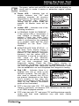
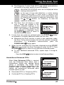
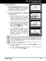
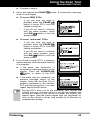
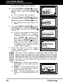
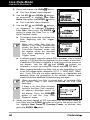
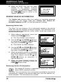
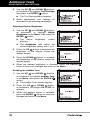
Adjustments After Battery Installation
The first time the Scan Tool is turned on, you must select the desired
display language (English, French or Spanish) and unit of measurement
(USA or Metric) as follows:
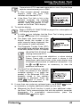
1. Press the POWER/LINK
turn the Scan Tool “ON.”
The Select
displays.
Language
button to
screen
and DOWN
buttons,
2. Use the UP
as necessary, to highlight the desired
display language.
3. When the desired display language is selected, press the ENTER
button to confirm your selection.
6
FixAssist™
About the Scan Tool
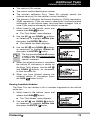
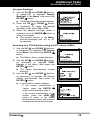
BATTERY REPLACEMENT
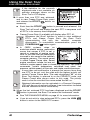
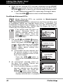
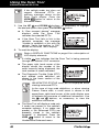
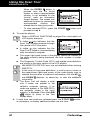
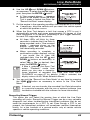
The Select Unit screen displays.
and DOWN
buttons,
4. Use the UP
as necessary, to highlight the desired
unit of measurement.
5. When the desired unit of measurement
button
is selected, press the ENTER
to confirm your selection.
After the initial language and unit of measurement selections
are performed, these, as well as other settings, can be
changed as desired. Proceed to “ADJUSTMENTS AND
SETTINGS” on page 77 for further instructions.
FixAssist™
7
Scan Tool Controls
CONTROLS AND INDICATORS
CONTROLS AND INDICATORS
12
11
8
7
9
10
1
2
4
3
5
6
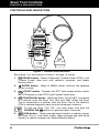
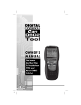
Figure 1. Controls and Indicators
See Figure 1 for the locations of items 1 through 12, below.
1.
ERASE button - Erases Diagnostic Trouble Codes (DTCs), and
“Freeze Frame” data from your vehicle’s computer, and resets
Monitor status.
2.
ENTER button - When in MENU mode, confirms the selected
option or value.
3.
DTC/FF button - Displays the DTC View screen and/or scrolls
the LCD display to view DTCs and Freeze Frame data.
4.
POWER/LINK button - When the Scan Tool IS NOT connected
to a vehicle, turns the Scan Tool “On” and “Off”. When the Scan
Tool is connected to a vehicle, links the Scan Tool to the vehicle’s
PCM to retrieve diagnostic data from the computer’s memory.
To turn the Scan Tool "On", you must press and hold the
POWER/LINK
button for approximately 3 seconds.
5.
8
LD/M button – When pressed while linked to a vehicle, places
the Scan Tool in "Live Data" mode. When pressed and held while
linked to a vehicle, displays the “Mode Selection Menu.”
FixAssist™
Scan Tool Controls
DISPLAY FUNCTIONS
6.
DOWN button - When in MENU mode, scrolls DOWN through
the menu and submenu selection options. When LINKED to a
vehicle, scrolls DOWN through the current display screen to display
any additional data.
7.
UP button - When in MENU mode, scrolls UP through the menu
and submenu selection options. When LINKED to a vehicle, scrolls
UP through the current display screen to display any additional data.
8. GREEN LED - Indicates that all engine systems are running
normally (all Monitors on the vehicle are active and performing their
diagnostic testing, and no DTCs are present).
9. YELLOW LED - Indicates there is a possible problem. A “Pending”
DTC is present and/or some of the vehicle’s emission monitors have
not run their diagnostic testing.
10. RED LED - Indicates there is a problem in one or more of the
vehicle’s systems. The red LED is also used to show that DTC(s)
are present. DTCs are shown on the Scan Tool’s display. In this
case, the Malfunction Indicator (“Check Engine”) lamp on the
vehicle’s instrument panel will light steady on.
11. Display - Displays settings Menu and submenus, test results, Scan
Tool functions and Monitor status information. See DISPLAY
FUNCTIONS, following, for more details.
12. CABLE - Connects the Scan Tool to the vehicle’s Data Link
Connector (DLC).
DISPLAY FUNCTIONS
2
1
11 12
13
3
4
5
6
14
7
10
8
9
Figure 2. Display Functions
See Figure 2 for the locations of items 1 through 14, following.
1. I/M MONITOR STATUS field - Identifies the I/M Monitor status area.
FixAssist™
9
Scan Tool Controls
DISPLAY FUNCTIONS
2. Monitor icons - Indicate which Monitors are supported by the
vehicle under test, and whether or not the associated Monitor has
run its diagnostic testing (Monitor status). When a Monitor icon is
solid, it indicates that the associated Monitor has completed its
diagnostic testing. When a Monitor icon is flashing, it indicates that
the vehicle supports the associated Monitor, but the Monitor has not
yet run its diagnostic testing.
3.
Vehicle icon - Indicates whether or not the Scan Tool is being
properly powered through the vehicle’s Data Link Connector (DLC).
A visible icon indicates that the Scan Tool is being powered through
the vehicle’s DLC connector.
4.
Link icon - Indicates whether or not the Scan Tool is
communicating (linked) with the vehicle’s on-board computer. When
visible, the Scan Tool is communicating with the computer. If the
Link icon is not visible, the Scan Tool is not communicating with the
computer.
5.
Computer icon - When this icon is visible it indicates that the
Scan Tool is linked to a personal computer. Optional software is
available that makes it possible to upload retrieved data to a
personal computer.
6.
Scan Tool Internal Battery icon - When visible, indicates the
Scan Tool batteries are “low” and should be replaced. If the
batteries are not replaced when the battery symbol is "on", all 3
LEDs will light up as a last resort indicator to warn you that the
batteries need replacement. No data will be displayed on screen
when all 3 LEDs are lit.
7. DTC Display Area - Displays the Diagnostic Trouble Code (DTC)
number. Each fault is assigned a code number that is specific to that
fault.
8. Test Data Display Area - Displays DTC definitions, Freeze Frame
data, Live Data and other pertinent test information messages.
9. FREEZE FRAME icon - Indicates that there is Freeze Frame data
from “Priority Code” (Code #1) stored in the vehicle’s computer
memory.
10. PERMANENT icon - Indicates the currently displayed DTC is a
“Permanent” code.
11. PENDING icon - Indicates the currently displayed DTC is a
“Pending” code.
12. MIL icon - Indicates the status of the Malfunction Indicator Lamp
(MIL). The MIL icon is visible only when a DTC has commanded the
MIL on the vehicle’s dashboard to light.
13. Code Number Sequence - The Scan Tool assigns a sequence
number to each DTC that is present in the computer’s memory,
starting with “01.” This number indicates which code is currently
displayed. Code number “01” is always the highest priority code,
and the one for which “Freeze Frame” data has been stored.
10
FixAssist™
Scan Tool Controls
DISPLAY FUNCTIONS
If “01” is a “Pending” code, there may or may not be “Freeze
Frame” data stored in memory.
14. Code Enumerator - Indicates the total number of codes retrieved
from the vehicle’s computer.
FixAssist™
11
Onboard Diagnostics
COMPUTER ENGINE CONTROLS
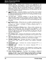
COMPUTER ENGINE CONTROLS
The Introduction of Electronic Engine Controls
Electronic Computer Control Systems make it possible
for vehicle manufacturers to comply with the tougher
emissions and fuel efficiency standards mandated by
State and Federal Governments.
As a result of increased air pollution (smog) in large cities,
such as Los Angeles, the California Air Resources Board
(CARB) and the Environmental Protection Agency (EPA)
set new regulations and air pollution standards to deal with
the problem. To further complicate matters, the energy crisis of
the early 1970s caused a sharp increase in fuel prices over a
short period. As a result, vehicle manufacturers were not only
required to comply with the new emissions standards, they also
had to make their vehicles more fuel-efficient. Most vehicles
were required to meet a miles-per-gallon (MPG) standard set by the U.S.
Federal Government.
Precise fuel delivery and spark timing are needed to reduce vehicle
emissions. Mechanical engine controls in use at the time (such as
ignition points, mechanical spark advance and the carburetor)
responded too slowly to driving conditions to properly control fuel
delivery and spark timing. This made it difficult for vehicle manufacturers
to meet the new standards.
A new Engine Control System had to be designed and integrated with
the engine controls to meet the stricter standards. The new system had
to:
Respond instantly to supply the proper mixture of air and fuel for any
driving condition (idle, cruising, low-speed driving, high-speed
driving, etc.).
Calculate instantly the best time to “ignite” the air/fuel mixture for
maximum engine efficiency.
Perform both these tasks without affecting vehicle performance or
fuel economy.
Vehicle Computer Control Systems can perform millions of calculations
each second. This makes them an ideal substitute for the slower
mechanical engine controls. By switching from mechanical to electronic
engine controls, vehicle manufacturers are able to control fuel delivery
and spark timing more precisely. Some newer Computer Control
Systems also provide control over other vehicle functions, such as
transmission, brakes, charging, body, and suspension systems.
12
FixAssist™
Onboard Diagnostics
COMPUTER ENGINE CONTROLS
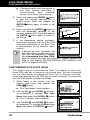
The Basic Engine Computer Control System
The Computer Control System consists of an on-board
computer and several related control devices (sensors,
switches, and actuators).
The on-board computer is the heart of the Computer
Control System. The computer contains several programs
with preset reference values for air/fuel ratio, spark or
ignition timing, injector pulse width, engine speed, etc.
Separate values are provided for various driving conditions,
such as idle, low speed driving, high-speed driving, low load,
or high load. The preset reference values represent the ideal
air/fuel mixture, spark timing, transmission gear selection,
etc., for any driving condition. These values are programmed
by the vehicle manufacturer, and are specific to each vehicle model.
Most on-board computers are located inside the vehicle behind the dashboard,
under the passenger’s or driver’s seat, or behind the right kick panel. However,
some manufacturers may still position it in the engine compartment.
Vehicle sensors, switches, and actuators are located throughout the
engine, and are connected by electrical wiring to the on-board computer.
These devices include oxygen sensors, coolant temperature sensors,
throttle position sensors, fuel injectors, etc. Sensors and switches are
input devices. They provide signals representing current engine
operating conditions to the computer. Actuators are output devices. They
perform actions in response to commands received from the computer.
The on-board computer receives information inputs from sensors and
switches located throughout the engine. These devices monitor critical
engine conditions such as coolant temperature, engine speed, engine
load, throttle position, air/fuel ratio etc.
The computer compares the values received from these sensors with its
preset reference values, and makes corrective actions as needed so
that the sensor values always match the preset reference values for the
current driving condition. The computer makes adjustments by
commanding other devices such as the fuel injectors, idle air control,
EGR valve or Ignition Module to perform these actions.
TYPICAL COMPUTER
CONTROL SYSTEM
OUTPUT DEVICES
Fuel Injectors
Idle Air Control
EGR Valve
Ignition Module
On-Board
Computer
INPUT DEVICES
Coolant Temperature Sensor
Throttle Position Sensor
Fuel Injectors
FixAssist™
INPUT DEVICES
Oxygen Sensors
13
Onboard Diagnostics
COMPUTER ENGINE CONTROLS
Vehicle operating conditions are constantly changing. The computer
continuously makes adjustments or corrections (especially to the air/fuel
mixture and spark timing) to keep all the engine systems operating
within the preset reference values.
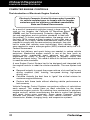
On-Board Diagnostics - First Generation (OBD1)
With the exception of some 1994 and 1995 vehicles,
most vehicles from 1982 to 1995 are equipped with
some type of first generation On-Board Diagnostics.
Beginning in 1988, California’s Air Resources Board
(CARB), and later the Environmental Protection Agency (EPA)
required vehicle manufacturers to include a self-diagnostic
program in their on-board computers. The program would be
capable of identifying emissions-related faults in a system. The
first generation of Onboard Diagnostics came to be known as
OBD1.
OBD1 is a set of self-testing and diagnostic instructions
programmed into the vehicle’s on-board computer. The
programs are specifically designed to detect failures in the sensors,
actuators, switches and wiring of the various vehicle emissions-related
systems. If the computer detects a failure in any of these components or
systems, it lights an indicator on the dashboard to alert the driver. The
indicator lights only when an emissions-related problem is detected.
The computer also assigns a numeric code for each specific problem
that it detects, and stores these codes in its memory for later retrieval.
These codes can be retrieved from the computer’s memory with the use
of a “Code Reader” or a “Scan Tool.”
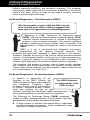
On-Board Diagnostics - Second Generation (OBD2)
In addition to performing all the
functions of the OBD1 System, the
The OBD2 System is
OBD2 System has been enhanced with
an enhancement of the
new Diagnostic Programs. These
OBD1 System.
programs closely monitor the functions
of various emissions-related components and systems (as well as other
systems) and make this information readily available (with
the proper equipment) to the technician for evaluation.
The California Air Resources Board (CARB) conducted
studies on OBD1 equipped vehicles. The information that was
gathered from these studies showed the following:
14
A large number of vehicles had deteriorating or degraded
emissions-related components. These components were
causing an increase in emissions.
FixAssist™
Onboard Diagnostics
COMPUTER ENGINE CONTROLS
Because OBD1 systems only detect failed components, the
degraded components were not setting codes.
Some emissions problems related to degraded components only
occur when the vehicle is being driven under a load. The emission
checks being conducted at the time were not performed under
simulated driving conditions. As a result, a significant number of
vehicles with degraded components were passing Emissions Tests.
Codes, code definitions, diagnostic connectors, communication
protocols and emissions terminology were different for each
manufacturer. This caused confusion for the technicians working on
different make and model vehicles.
To address the problems made evident by this study, CARB and the
EPA passed new laws and standardization requirements. These laws
required that vehicle manufacturers to equip their new vehicles with
devices capable of meeting all of the new emissions standards and
regulations. It was also decided that an enhanced on-board diagnostic
system, capable of addressing all of these problems, was needed. This
new system is known as “On-Board Diagnostics Generation Two
(OBD2).” The primary objective of the OBD2 system is to comply with
the latest regulations and emissions standards established by CARB
and the EPA.
The Main Objectives of the OBD2 System are:
To detect degraded and/or failed emissions-related components or
systems that could cause tailpipe emissions to exceed by 1.5 times
the Federal Test Procedure (FTP) standard.
To expand emissions-related system monitoring. This includes a set
of computer run diagnostics called Monitors. Monitors perform
diagnostics and testing to verify that all emissions-related
components and/or systems are operating correctly and within the
manufacturer’s specifications.
To use a standardized Diagnostic Link Connector (DLC) in all
vehicles. (Before OBD2, DLCs were of different shapes and sizes.)
To standardize the code numbers, code definitions and language
used to describe faults. (Before OBD2, each vehicle manufacturer
used their own code numbers, code definitions and language to
describe the same faults.)
To expand the operation of the Malfunction Indicator Lamp (MIL).
To standardize communication procedures and protocols between
the diagnostic equipment (Scan Tools, Code Readers, etc.) and the
vehicle’s on-board computer.
OBD2 Terminology
The following terms and their definitions are related to OBD2 systems.
Read and reference this list as needed to aid in the understanding of
OBD2 systems.
FixAssist™
15
Onboard Diagnostics
COMPUTER ENGINE CONTROLS
Powertrain Control Module (PCM) - The PCM is the OBD2
accepted term for the vehicle’s “on-board computer.” In addition
to controlling the engine management and emissions systems,
the PCM also participates in controlling the powertrain
(transmission) operation. Most PCMs also have the ability to
communicate with other computers on the vehicle (ABS, ride
control, body, etc.).
Monitor - Monitors are “diagnostic routines” programmed into the
PCM. The PCM utilizes these programs to run diagnostic tests, and
to monitor operation of the vehicle’s emissions-related components
or systems to ensure they are operating correctly and within the
vehicle’s manufacturer specifications. Currently, up to eleven
Monitors are used in OBD2 systems. Additional Monitors will be
added as the OBD2 system is further developed.
Not all vehicles support all fifteen Monitors.
16
Enabling Criteria - Each Monitor is designed to test and monitor
the operation of a specific part of the vehicle’s emissions system
(EGR system, oxygen sensor, catalytic converter, etc.). A specific
set of “conditions” or “driving procedures” must be met before the
computer can command a Monitor to run tests on its related system.
These “conditions” are known as “Enabling Criteria.” The
requirements and procedures vary for each Monitor. Some Monitors
only require the ignition key to be turned “On” for them to run and
complete their diagnostic testing. Others may require a set of
complex procedures, such as, starting the vehicle when cold,
bringing it to operating temperature, and driving the vehicle under
specific conditions before the Monitor can run and complete its
diagnostic testing.
Monitor Has/Has Not Run - The terms “Monitor has run” or
“Monitor has not run” are used throughout this manual. “Monitor
has run,” means the PCM has commanded a particular Monitor to
perform the required diagnostic testing on a system to ensure the
system is operating correctly (within factory specifications). The term
“Monitor has not run” means the PCM has not yet commanded a
particular Monitor to perform diagnostic testing on its associated part
of the emissions system.
Trip - A Trip for a particular Monitor requires that the vehicle is
being driven in such a way that all the required “Enabling Criteria”
for the Monitor to run and complete its diagnostic testing are met.
The “Trip Drive Cycle” for a particular Monitor begins when the
ignition key is turned “On.” It is successfully completed when all the
“Enabling Criteria” for the Monitor to run and complete its diagnostic
testing are met by the time the ignition key is turned “Off.” Since
each of the eleven monitors is designed to run diagnostics and
testing on a different part of the engine or emissions system, the
“Trip Drive Cycle” needed for each individual Monitor to run and
complete varies.
FixAssist™
Onboard Diagnostics
DIAGNOSTIC TROUBLE CODES (DTCs)
OBD2 Drive Cycle - An OBD2 Drive Cycle is an extended set of
driving procedures that takes into consideration the various types of
driving conditions encountered in real life. These conditions may
include starting the vehicle when it is cold, driving the vehicle at a
steady speed (cruising), accelerating, etc. An OBD2 Drive Cycle
begins when the ignition key is turned “On” (when cold) and ends
when the vehicle has been driven in such a way as to have all the
“Enabling Criteria” met for all its applicable Monitors. Only those
trips that provide the Enabling Criteria for all Monitors applicable to
the vehicle to run and complete their individual diagnostic tests
qualify as an OBD2 Drive Cycle. OBD2 Drive Cycle requirements
vary from one model of vehicle to another. Vehicle manufacturers
set these procedures. Consult your vehicle’s service manual for
OBD2 Drive Cycle procedures.
Do not confuse a “Trip” Drive Cycle with an OBD2 Drive Cycle. A
“Trip” Drive Cycle provides the “Enabling Criteria” for one specific
Monitor to run and complete its diagnostic testing. An OBD2 Drive
Cycle must meet the “Enabling Criteria” for all Monitors on a
particular vehicle to run and complete their diagnostic testing.
Warm-up Cycle - Vehicle operation after an engine off period where
engine temperature rises at least 40°F (22°C) from its temperature
before starting, and reaches at least 160°F (70°C). The PCM uses
warm-up cycles as a counter to automatically erase a specific code
and related data from its memory. When no faults related to the
original problem are detected within a specified number of warm-up
cycles, the code is erased automatically.
DIAGNOSTIC TROUBLE CODES (DTCs)
Diagnostic Trouble Codes (DTCs) are
meant to guide you to the proper
service procedure in the vehicle’s
service manual. DO NOT replace parts
based only on DTCs without first
consulting the vehicle’s service manual
for proper testing procedures for that
particular system, circuit or component.
Diagnostic Trouble
Codes (DTCs) are
codes that identify a
specific problem area.
DTCs are alphanumeric codes that are used to identify a
problem that is present in any of the systems that are
monitored by the on-board computer (PCM). Each trouble
code has an assigned message that identifies the circuit,
component or system area where the problem was found.
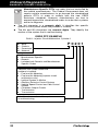
OBD2 diagnostic trouble codes are made up of five characters:
The 1st character is a letter. It identifies the “main system”
where the fault occurred (Body, Chassis, Powertrain, or Network).
The 2nd character is a numeric digit. It identifies the “type” of code
(Generic or Manufacturer-Specific).
Generic DTCs are codes that are used by all vehicle
manufacturers. The standards for generic DTCs, as well as
their definitions, are set by the Society of Automotive
Engineers (SAE).
FixAssist™
17
Onboard Diagnostics
DIAGNOSTIC TROUBLE CODES (DTCs)
Manufacturer-Specific DTCs are codes that are controlled by
the vehicle manufacturers. The Federal Government does not
require vehicle manufacturers to go beyond the standardized
generic DTCs in order to comply with the new OBD2
emissions standards. However, manufacturers are free to
expand beyond the standardized codes to make their systems
easier to diagnose.
The 3rd character is a numeric digit. It identifies the specific
system or sub-system where the problem is located.
The 4th and 5th characters are numeric digits. They identify the
section of the system that is malfunctioning.
OBD2 DTC EXAMPLE
P0201 - Injector Circuit Malfunction, Cylinder 1
B
C
P
U
-
Body
Chassis
Powertrain
Network
0
1
2
3
-
Generic
Manufacturer Specific
Generic
Includes both Generic and Manufacturer
Specific Codes
P0201
Identifies the system where the
problem is located:
1 - Fuel and Air Metering
2 - Fuel and Air Metering (injector circuit
malfunction only)
3 - Ignition System or Misfire
4 - Auxiliary Emission Control System
5 - Vehicle Speed Control and Idle Control
System
6 - Computer Output Circuits
7 - Transmission
8 - Transmission
Identifies what section of the system
is malfunctioning
18
FixAssist™
Onboard Diagnostics
DIAGNOSTIC TROUBLE CODES (DTCs)
DTCs and MIL Status
When the vehicle’s on-board computer detects
a failure in an emissions-related component or
system, the computer’s internal diagnostic
program assigns a diagnostic trouble code
(DTC) that points to the system (and subsystem)
where the fault was found. The diagnostic
program saves the code in the computer’s
memory. It records a “Freeze Frame” of
conditions present when the fault was found, and lights the Malfunction
Indicator Lamp (MIL). Some faults require detection for two trips in a row
before the MIL is turned on.
The “Malfunction Indicator Lamp” (MIL) is the accepted term
used to describe the lamp on the dashboard that lights to warn
the driver that an emissions-related fault has been found.
Some manufacturers may still call this lamp a “Check Engine”
or “Service Engine Soon” light.
There are two types of DTCs used for emissions-related faults: Type “A”
and Type “B.” Type “A” codes are “One-Trip” codes; Type “B” DTCs are
usually Two-Trip DTCs.
When a Type “A” DTC is found on the First Trip, the following events
take place:
The computer commands the MIL “On” when the failure is first found.
If the failure causes a severe misfire that may cause damage to the
catalytic converter, the MIL “flashes” once per second. The MIL
continues to flash as long as the condition exists. If the condition
that caused the MIL to flash is no longer present, the MIL will light
“steady” On.
A DTC is saved in the computer’s memory for later retrieval.
A “Freeze Frame” of the conditions present in the engine or emissions
system when the MIL was ordered “On” is saved in the computer’s
memory for later retrieval. This information shows fuel system status
(closed loop or open loop), engine load, coolant temperature, fuel trim
value, MAP vacuum, engine RPM and DTC priority.
When a Type “B” DTC is found on the First Trip, the following events
take place:
The computer sets a Pending DTC, but the MIL is not ordered “On.”
“Freeze Frame” data may or may not be saved at this time
depending on manufacturer. The Pending DTC is saved in the
computer’s memory for later retrieval.
If the failure is found on the second consecutive trip, the MIL is
ordered “On.” “Freeze Frame” data is saved in the computer’s
memory.
If the failure is not found on the second Trip, the Pending DTC is
erased from the computer’s memory.
The MIL will stay lit for both Type “A” and Type “B” codes until one of
the following conditions occurs:
FixAssist™
19
Onboard Diagnostics
OBD2 MONITORS
If the conditions that caused the MIL to light are no longer present
for the next three trips in a row, the computer automatically turns the
MIL “Off” if no other emissions-related faults are present. However,
the DTCs remain in the computer’s memory as a history code for 40
warm-up cycles (80 warm-up cycles for fuel and misfire faults). The
DTCs are automatically erased if the fault that caused them to be
set is not detected again during that period.
Misfire and fuel system faults require three trips with “similar
conditions” before the MIL is turned “Off.” These are trips where the
engine load, RPM and temperature are similar to the conditions
present when the fault was first found.
After the MIL has been turned off, DTCs and Freeze Frame
data stay in the computer’s memory.
Erasing the DTCs from the computer’s memory can also turn off the
MIL. See ERASING DIAGNOSTIC TROUBLE CODES (DTCs) on
page 54, before erasing codes from the computer’s memory. If a
Diagnostic Tool or Scan Tool is used to erase the codes, Freeze
Frame data will also be erased.
OBD2 MONITORS
To ensure the correct operation of the various emissions-related
components and systems, a diagnostic program was developed and
installed in the vehicle’s on-board computer. The program has several
procedures and diagnostic strategies. Each procedure or diagnostic
strategy is made to monitor the operation of, and run diagnostic tests on,
a specific emissions-related component or system. These tests ensure
the system is running correctly and is within the manufacturer’s
specifications. On OBD2 systems, these procedures and diagnostic
strategies are called “Monitors.”
Currently, fifteen Monitors are supported by OBD2 systems. Additional
monitors may be added as a result of Government regulations as the
OBD2 system grows and matures. Not all vehicles support all fifteen
Monitors. Additionally, some Monitors are supported by “spark ignition”
vehicles only, while others are supported by “compression ignition”
vehicles only.
Monitor operation is either “Continuous” or “Non-Continuous,”
depending on the specific monitor.
Continuous Monitors
Three of these Monitors are designed to constantly monitor their
associated components and/or systems for proper operation.
Continuous Monitors run constantly when the engine is running. The
Continuous Monitors are:
Comprehensive Component Monitor (CCM)
Misfire Monitor
Fuel System Monitor
20
FixAssist™
Onboard Diagnostics
OBD2 MONITORS
Non-Continuous Monitors
The other twelve Monitors are “non-continuous” Monitors. “Noncontinuous” Monitors perform and complete their testing once per trip.
The “non-continuous” Monitors are:
Oxygen Sensor Monitor
Oxygen Sensor Heater Monitor
Catalyst Monitor
Heated Catalyst Monitor
EGR System Monitor
EVAP System Monitor
Secondary Air System Monitor
The following Monitors became standard beginning in 2010.
The majority of vehicles produced before this time will not
support these Monitors
NMHC Monitor
NOx Adsorber Monitor
Boost Pressure System Monitor
Exhaust Gas Sensor Monitor
PM Filter Monitor
The following provides a brief explanation of the function of each Monitor:
Comprehensive Component Monitor (CCM) - This Monitor
continuously checks all inputs and outputs from sensors,
actuators, switches and other devices that provide a signal to the
computer. The Monitor checks for shorts, opens, out of range value,
functionality and “rationality.”
Rationality: Each input signal is compared against all other
inputs and against information in the computer’s memory to see
if it makes sense under the current operating conditions.
Example: The signal from the throttle position sensor indicates
the vehicle is in a wide-open throttle condition, but the vehicle is
really at idle, and the idle condition is confirmed by the signals
from all other sensors. Based on the input data, the computer
determines that the signal from the throttle position sensor is not
rational (does not make sense when compared to the other
inputs). In this case, the signal would fail the rationality test.
The CCM is supported by both “spark ignition” vehicles and
“compression ignition” vehicles. The CCM may be either a “One-Trip” or
a “Two-Trip” Monitor, depending on the component.
FixAssist™
21
Onboard Diagnostics
OBD2 MONITORS
Fuel System Monitor - This Monitor uses a Fuel System
Correction program, called Fuel Trim, inside the on-board
computer. Fuel Trim is a set of positive and negative values that
represent adding or subtracting fuel from the engine. This program is
used to correct for a lean (too much air/not enough fuel) or rich (too
much fuel/not enough air) air-fuel mixture. The program is designed to
add or subtract fuel, as needed, up to a certain percent. If the correction
needed is too large and exceeds the time and percent allowed by the
program, a fault is indicated by the computer.
The Fuel System Monitor is supported by both “spark ignition” vehicles
and “compression ignition” vehicles. The Fuel System Monitor may be a
“One-Trip” or “Two-Trip” Monitor, depending on the severity of the
problem.
Misfire Monitor - This Monitor continuously checks for engine misfires.
A misfire occurs when the air-fuel mixture in the cylinder does not ignite.
The misfire Monitor uses changes in crankshaft speed to sense an engine
misfire. When a cylinder misfires, it no longer contributes to the speed of the
engine, and engine speed decreases each time the affected cylinder(s) misfire.
The misfire Monitor is designed to sense engine speed fluctuations and
determine from which cylinder(s) the misfire is coming, as well as how bad the
misfire is. There are three types of engine misfires, Types 1, 2, and 3.
- Type 1 and Type 3 misfires are two-trip monitor faults. If a fault is sensed
on the first trip, the computer temporarily saves the fault in its memory as
a Pending Code. The MIL is not commanded on at this time. If the fault is
found again on the second trip, under similar conditions of engine speed,
load and temperature, the computer commands the MIL “On,” and the
code is saved in its long term memory.
- Type 2 misfires are the most severe type of misfire. When a Type 2
misfire is sensed on the first trip, the computer commands the MIL to
light when the misfire is sensed. If the computer determines that a
Type 2 misfire is severe , and may cause catalytic converter damage,
it commands the MIL to “flash” once per second as soon as the
misfire is sensed. When the misfire is no longer present, the MIL
reverts to steady “On” condition.
The Misfire Monitor is supported by both “spark ignition” vehicles and
“compression ignition” vehicles.
Catalyst Monitor - The catalytic converter is a device that is
installed downstream of the exhaust manifold. It helps to oxidize
(burn) the unburned fuel (hydrocarbons) and partially burned fuel
(carbon monoxide) left over from the combustion process. To
accomplish this, heat and catalyst materials inside the converter react
with the exhaust gases to burn the remaining fuel. Some materials
inside the catalytic converter also have the ability to store oxygen, and
release it as needed to oxidize hydrocarbons and carbon monoxide. In
the process, it reduces vehicle emissions by converting the polluting
gases into carbon dioxide and water.
The computer checks the efficiency of the catalytic converter by
monitoring the oxygen sensors used by the system. One sensor is located
before (upstream of) the converter; the other is located after (downstream
of) the converter. If the catalytic converter loses its ability to store oxygen,
22
FixAssist™
Onboard Diagnostics
OBD2 MONITORS
the downstream sensor signal voltage becomes almost the same as the
upstream sensor signal. In this case, the monitor fails the test.
The Catalyst Monitor is supported by “spark ignition” vehicles only. The
Catalyst Monitor is a “Two-Trip” Monitor. If a fault is found on the first
trip, the computer temporarily saves the fault in its memory as a
Pending Code. The computer does not command the MIL on at this time.
If the fault is sensed again on the second trip, the computer commands
the MIL “On” and saves the code in its long-term memory.
Heated Catalyst Monitor - Operation of the “heated” catalytic
converter is similar to the catalytic converter. The main difference
is that a heater is added to bring the catalytic converter to its operating
temperature more quickly. This helps reduce emissions by reducing the
converter’s down time when the engine is cold. The Heated Catalyst
Monitor performs the same diagnostic tests as the catalyst Monitor, and
also tests the catalytic converter’s heater for proper operation.
The Heated Catalyst Monitor is supported by “spark ignition” vehicles
only. This Monitor is also a “Two-Trip” Monitor.
Exhaust Gas Recirculation (EGR) Monitor - The Exhaust Gas
Recirculation (EGR) system helps reduce the formation of
Oxides of Nitrogen during combustion. Temperatures above 2500°F
cause nitrogen and oxygen to combine and form Oxides of Nitrogen in
the combustion chamber. To reduce the formation of Oxides of Nitrogen,
combustion temperatures must be kept below 2500°F. The EGR system
recirculates small amounts of exhaust gas back into the intake manifold,
where it is mixed with the incoming air/fuel mixture. This reduces
combustion temperatures by up to 500°F. The computer determines
when, for how long, and how much exhaust gas is recirculated back to
the intake manifold. The EGR Monitor performs EGR system function
tests at preset times during vehicle operation.
The EGR Monitor is supported by both “spark ignition” vehicles and
“compression ignition” vehicles. The EGR Monitor is a “Two-Trip”
Monitor. If a fault is found on the first trip, the computer temporarily
saves the fault in its memory as a Pending Code. The computer does
not command the MIL on at this time. If the fault is sensed again on the
second trip, the computer commands the MIL “On,” and saves the code
in its long-term memory.
Evaporative System (EVAP) Monitor - OBD2 vehicles are
equipped with a fuel Evaporative system (EVAP) that helps
prevent fuel vapors from evaporating into the air. The EVAP system
carries fumes from the fuel tank to the engine where they are burned
during combustion. The EVAP system may consist of a charcoal
canister, fuel tank cap, purge solenoid, vent solenoid, flow monitor, leak
detector and connecting tubes, lines and hoses.
Fumes are carried from the fuel tank to the charcoal canister by hoses
or tubes. The fumes are stored in the charcoal canister. The computer
controls the flow of fuel vapors from the charcoal canister to the engine
via a purge solenoid. The computer energizes or de-energizes the purge
solenoid (depending on solenoid design). The purge solenoid opens a
valve to allow engine vacuum to draw the fuel vapors from the canister
FixAssist™
23
Onboard Diagnostics
OBD2 MONITORS
into the engine where the vapors are burned. The EVAP Monitor checks
for proper fuel vapor flow to the engine, and pressurizes the system to
test for leaks. The computer runs this Monitor once per trip.
The EVAP Monitor is supported by “spark ignition” vehicles only. The
EVAP Monitor is a “Two-Trip” Monitor. If a fault is found on the first trip,
the computer temporarily saves the fault in its memory as a Pending
Code. The computer does not command the MIL on at this time. If the
fault is sensed again on the second trip, the PCM commands the MIL
“On,” and saves the code in its long-term memory.
Oxygen Sensor Heater Monitor - The Oxygen Sensor Heater
Monitor tests the operation of the oxygen sensor’s heater. There
are two modes of operation on a computer-controlled vehicle: “openloop” and “closed-loop.” The vehicle operates in open-loop when the
engine is cold, before it reaches normal operating temperature. The
vehicle also goes to open-loop mode at other times, such as heavy load
and full throttle conditions. When the vehicle is running in open-loop, the
oxygen sensor signal is ignored by the computer for air/fuel mixture
corrections. Engine efficiency during open-loop operation is very low,
and results in the production of more vehicle emissions.
Closed-loop operation is the best condition for both vehicle emissions
and vehicle operation. When the vehicle is operating in closed-loop, the
computer uses the oxygen sensor signal for air/fuel mixture corrections.
In order for the computer to enter closed-loop operation, the oxygen
sensor must reach a temperature of at least 600°F. The oxygen sensor
heater helps the oxygen sensor reach and maintain its minimum
operating temperature (600°F) more quickly, to bring the vehicle into
closed-loop operation as soon as possible.
The Oxygen Sensor Heater Monitor is supported by “spark ignition”
vehicles only. The Oxygen Sensor Heater Monitor is a “Two-Trip”
Monitor. If a fault is found on the first trip, the computer temporarily
saves the fault in its memory as a Pending Code. The computer does
not command the MIL on at this time. If the fault is sensed again on the
second trip, the computer commands the MIL “On,” and saves the code
in its long-term memory.
Oxygen Sensor Monitor - The Oxygen Sensor monitors how
much oxygen is in the vehicle’s exhaust. It generates a varying
voltage of up to one volt, based on how much oxygen is in the exhaust
gas, and sends the signal to the computer. The computer uses this
signal to make corrections to the air/fuel mixture. If the exhaust gas has
a large amount of oxygen (a lean air/fuel mixture), the oxygen sensor
generates a “low” voltage signal. If the exhaust gas has very little
oxygen (a rich mixture condition), the oxygen sensor generates a “high”
voltage signal. A 450mV signal indicates the most efficient, and least
polluting, air/fuel ratio of 14.7 parts of air to one part of fuel.
The oxygen sensor must reach a temperature of at least 600-650°F,
and the engine must reach normal operating temperature, for the
computer to enter into closed-loop operation. The oxygen sensor only
functions when the computer is in closed-loop. A properly operating
oxygen sensor reacts quickly to any change in oxygen content in the
24
FixAssist™
Onboard Diagnostics
OBD2 MONITORS
exhaust stream. A faulty oxygen sensor reacts slowly, or its voltage
signal is weak or missing.
The Oxygen Sensor Monitor is supported by “spark ignition” vehicles
only. The Oxygen Sensor Monitor is a “Two-Trip” monitor. If a fault is
found on the first trip, the computer temporarily saves the fault in its
memory as a Pending Code. The computer does not command the MIL
on at this time. If the fault is sensed again on the second trip, the
computer commands the MIL “On,” and saves the code in its long-term
memory.
Secondary Air System Monitor - When a cold engine is first
started, it runs in open-loop mode. During open-loop operation,
the engine usually runs rich. A vehicle running rich wastes fuel and
creates increased emissions, such as carbon monoxide and some
hydrocarbons. A Secondary Air System injects air into the exhaust
stream to aid catalytic converter operation:
1. It supplies the catalytic converter with the oxygen it needs to oxidize
the carbon monoxide and hydrocarbons left over from the
combustion process during engine warm-up.
2. The extra oxygen injected into the exhaust stream also helps the
catalytic converter reach operating temperature more quickly during
warm-up periods. The catalytic converter must heat to operating
temperature to work properly.
The Secondary Air System Monitor checks for component integrity and
system operation, and tests for faults in the system. The computer runs
this Monitor once per trip.
The Secondary Air System Monitor is a “Two-Trip” monitor. If a fault is
found on the first trip, the computer temporarily saves this fault in its
memory as a Pending Code. The computer does not command the MIL
on at this time. If the fault is sensed again on the second trip, the
computer commands the MIL “On,” and saves the code in its long-term
memory.
Non-Methane Hydrocarbon Catalyst (NMHC) Monitor - The
non-methane hydrocarbon catalyst is a type of catalytic converter.
It helps to remove non-methane hydrocarbons (NMH) left over from the
combustion process from the exhaust stream. To accomplish this, heat
and catalyst materials react with the exhaust gases to convert NMH to
less harmful compounds. The computer checks the efficiency of the
catalyst by monitoring the quantity of NMH in the exhaust stream. The
monitor also verifies that sufficient temperature is present to aid in
particulate matter (PM) filter regeneration.
The NMHC Monitor is supported by “compression ignition” vehicles only.
The NMHC Monitor is a “Two-Trip” Monitor. If a fault is found on the first
trip, the computer temporarily saves the fault in its memory as a
Pending Code. The computer does not command the MIL on at this time.
If the fault is sensed again on the second trip, the computer commands
the MIL “On,” and saves the code in its long-term memory.
FixAssist™
25
Onboard Diagnostics
OBD2 MONITORS
NOx Aftertreatment Monitor - NOx aftertreatment is based on a
catalytic converter support that has been coated with a special
washcoat containing zeolites. NOx Aftertreatment is designed to reduce
oxides of nitrogen emitted in the exhaust stream. The zeolite acts as a
molecular "sponge" to trap the NO and NO2 molecules in the exhaust
stream. In some implementations, injection of a reactant before the
aftertreatment purges it. NO2 in particular is unstable, and will join with
hydrocarbons to produce H2O and N2. The NOx Aftertreatment Monitor
monitors the function of the NOx aftertreatment to ensure that tailpipe
emissions remain within acceptable limits.
The NOx Aftertreatment Monitor is supported by “compression ignition”
vehicles only. The NOx Aftertreatment Monitor is a “Two-Trip” Monitor. If
a fault is found on the first trip, the computer temporarily saves the fault
in its memory as a Pending Code. The computer does not command the
MIL on at this time. If the fault is sensed again on the second trip, the
computer commands the MIL “On,” and saves the code in its long-term
memory.
Boost Pressure System Monitor - The boost pressure system
serves to increase the pressure produced inside the intake
manifold to a level greater than atmospheric pressure. This increase in
pressure helps to ensure compete combustion of the air-fuel mixture.
The Boost Pressure System Monitor checks for component integrity and
system operation, and tests for faults in the system. The computer runs
this Monitor once per trip.
The Boost Pressure System Monitor is supported by “compression
ignition” vehicles only. The Boost Pressure System Monitor is a “TwoTrip” Monitor. If a fault is found on the first trip, the computer temporarily
saves the fault in its memory as a Pending Code. The computer does
not command the MIL on at this time. If the fault is sensed again on the
second trip, the computer commands the MIL “On,” and saves the code
in its long-term memory.
Exhaust Gas Sensor Monitor - The exhaust gas sensor is used
by a number of systems/monitors to determine the content of the
exhaust stream. The computer checks for component integrity, system
operation, and tests for faults in the system, as well as feedback faults
that may affect other emission control systems.
The Exhaust Gas Sensor Monitor is supported by “compression ignition”
vehicles only. The Exhaust Gas Sensor Monitor is a “Two-Trip” Monitor.
If a fault is found on the first trip, the computer temporarily saves the
fault in its memory as a Pending Code. The computer does not
command the MIL on at this time. If the fault is sensed again on the
second trip, the computer commands the MIL “On,” and saves the code
in its long-term memory.
26
FixAssist™
Onboard Diagnostics
OBD2 MONITORS
PM Filter Monitor - The particulate matter (PM) filter removes
particulate matter from the exhaust stream by filtration. The filter
has a honeycomb structure similar to a catalyst substrate, but with the
channels blocked at alternate ends. This forces the exhaust gas to flow
through the walls between the channels, filtering the particulate matter
out. The filters are self-cleaning by periodic modification of the exhaust
gas concentration in order to burn off the trapped particles (oxidizing the
particles to form CO2 and water). The computer monitors the efficiency
of the filter in trapping particulate matter, as well as the ability of the filter
to regenerate (self-clean).
The PM Filter Monitor is supported by “compression ignition” vehicles
only. The PM Filter Monitor is a “Two-Trip” Monitor. If a fault is found on
the first trip, the computer temporarily saves the fault in its memory as a
Pending Code. The computer does not command the MIL on at this time.
If the fault is sensed again on the second trip, the computer commands
the MIL “On,” and saves the code in its long-term memory.
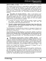
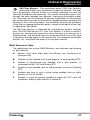
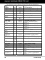
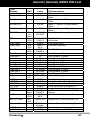
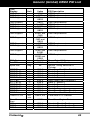
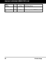
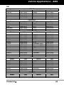
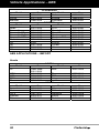
OBD2 Reference Table
The table below lists current OBD2 Monitors, and indicates the following
for each Monitor:
A.
Monitor Type (how often does the Monitor run; Continuous or
Once per trip)
B.
Number of trips needed, with a fault present, to set a pending DTC
C.
Number of consecutive trips needed, with a fault present, to
command the MIL “On” and store a DTC
D.
Number of trips needed, with no faults present, to erase a Pending
DTC
E.
Number and type of trips or drive cycles needed, with no faults
present, to turn off the MIL
F.
Number of warm-up periods needed to erase the DTC from the
computer’s memory after the MIL is turned off
FixAssist™
27
Onboard Diagnostics
OBD2 MONITORS
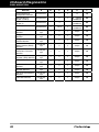
Name of
Monitor
A
B
C
D
E
F
Comprehensive
Component Monitor
Continuous
1
2
1
3
40
Misfire Monitor
(Type 1 and 3)
Continuous
1
2
1
3 - similar
conditions
80
Misfire Monitor
(Type 2)
Continuous
1
3 - similar
conditions
80
80
Fuel System Monitor
28
Continuous
1
1 or 2
1
3 - similar
conditions
Catalytic Converter
Monitor
Once per
trip
1
2
1
3 trips
40
Oxygen Sensor
Monitor
Once per
trip
1
2
1
3 trips
40
Oxygen Sensor
Heater Monitor
Once per
trip
1
2
1
3 trips
40
Exhaust Gas
Recirculation (EGR)
Monitor
Once per
trip
1
2
1
3 trips
40
Evaporative
Emissions Controls
Monitor
Once per
trip
1
2
1
3 trips
40
Secondary Air
System (AIR) Monitor
Once per
trip
1
2
1
3 trips
40
NMHC Monitor
Once per
trip
1
2
1
3 trips
40
NOx Adsorber
Monitor
Once per
trip
1
2
1
3 trips
40
Boost Pressure
System Monitor
Once per
trip
1
2
1
3 trips
40
Exhaust Gas Sensor
Monitor
Once per
trip
1
2
1
3 trips
40
PM Filter Monitor
Once per
trip
1
2
1
3 trips
40
FixAssist™
Preparation for Testing
PRELIMINARY VEHICLE DIAGNOSTIC WORKSHEET
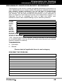
PRELIMINARY VEHICLE DIAGNOSTIC WORKSHEET
The purpose of this form is to help you gather preliminary information on
your vehicle before you retrieve codes. By having a complete account of
your vehicle's current problem(s), you will be able to systematically
pinpoint the problem(s) by comparing your answers to the fault codes
you retrieve. You can also provide this information to your mechanic to
assist in diagnosis and help avoid costly and unnecessary repairs. It is
important for you to complete this form to help you and/or your
mechanic have a clear understanding of your vehicle's problems.
NAME:
DATE:
VIN*:
YEAR:
MAKE:
MODEL:
ENGINE SIZE:
VEHICLE MILEAGE:
*VIN: Vehicle Identification Number, found at the base of the windshield
on a metallic plate, or at the driver door latch area (consult your vehicle
owner's manual for location).
TRANSMISSION:
Automatic
Manual
Please check all applicable items in each category.
DESCRIBE THE PROBLEM:
FixAssist™
29
Preparation for Testing
PRELIMINARY VEHICLE DIAGNOSTIC WORKSHEET
WHEN DID YOU FIRST NOTICE THE PROBLEM:
Just Started
Started Last Week
Started Last Month
Other:
m
LIST ANY REPAIRS DONE IN THE PAST SIX MONTHS:
PROBLEMS STARTING
No symptoms
Cranks, but will not start
Starts, but takes a long
time
Right after vehicle
comes to a stop
Will not crank
ENGINE QUITS OR STALLS
No symptoms
Right after starting
When shifting into gear
While idling
During steady-speed
driving
During acceleration
When parking
IDLING CONDITIONS
No symptoms
Is too slow at all times
Is too fast
Is sometimes too fast or
too slow
Is rough or uneven
Fluctuates up and down
RUNNING CONDITIONS
30
No symptoms
Backfires
Runs rough
Lacks power
Bucks and jerks
Misfires or cuts out
Engine knocks, pings or
rattles
Poor fuel economy
Surges
Hesitates or stumbles on
accelerations
Dieseling or run-on
FixAssist™
Preparation for Testing
PRELIMINARY VEHICLE DIAGNOSTIC WORKSHEET
AUTOMATIC TRANSMISSION PROBLEMS (if applicable)
No symptoms
Shifts too early or too late
Changes gear incorrectly
PROBLEM OCCURS
Morning
Vehicle does not move
when in gear
Jerks or bucks
Afternoon
Anytime
Hot
ENGINE TEMPERATURE WHEN PROBLEM OCCURS
Cold
Warm
DRIVING CONDITIONS WHEN PROBLEM OCCURS
Short - less than 2 miles
2 - 10 miles
Long - more than 10 miles
Stop and go
While turning
While braking
At gear engagement
With A/C operating
With headlights on
During acceleration
Mostly driving downhill
Mostly driving uphill
Mostly driving level
Mostly driving curvy
roads
Mostly driving rough
roads
DRIVING HABITS
Mostly city driving
Highway
Park vehicle inside
Park vehicle outside
Drive less than 10 miles per day
Drive 10 to 50 miles per day
Drive more than 50 miles per
day
GASOLINE USED
87 Octane
89 Octane
91 Octane
More than 91 Octane
WEATHER CONDITIONS WHEN PROBLEM OCCURS
32 - 55° F (0 - 13° C)
Below freezing (32° F / 0° C)
Above 55° F (13° C)
CHECK ENGINE LIGHT / DASH WARNING LIGHT
Sometimes ON
Always ON
Never ON
PECULIAR SMELLS
"Hot"
Sulfur ("rotten egg")
Burning rubber
Gasoline
Burning oil
Electrical
STRANGE NOISES
Rattle
Knock
FixAssist™
Squeak
Other
31
Preparation for Testing
BEFORE YOU BEGIN
BEFORE YOU BEGIN
The FixAssist Scan Tool aids in
monitoring
electronicand
emissions-related faults in your
vehicle and retrieving fault
codes related to malfunctions in
these systems. Mechanical
problems such as low oil level or
damaged hoses, wiring or electrical connectors can cause poor engine
performance and may also cause a fault code to set. Fix any known
mechanical problems before performing any test. See your vehicle’s
service manual or a mechanic for more information.
Check the following areas before starting any test:
32
Check the engine oil, power steering fluid, transmission fluid (if
applicable), engine coolant and other fluids for proper levels. Top off
low fluid levels if needed.
Make sure the air filter is clean and in good condition. Make sure all
air filter ducts are properly connected. Check the air filter ducts for
holes, rips or cracks.
Make sure all engine belts are in good condition. Check for cracked,
torn, brittle, loose or missing belts.
Make sure mechanical linkages to engine sensors (throttle, gearshift
position, transmission, etc.) are secure and properly connected. See
your vehicle’s service manual for locations.
Check all rubber hoses (radiator) and steel hoses (vacuum/fuel) for
leaks, cracks, blockage or other damage. Make sure all hoses are
routed and connected properly.
Make sure all spark plugs are clean and in good condition. Check
for damaged, loose, disconnected or missing spark plug wires.
Make sure the battery terminals are clean and tight. Check for
corrosion or broken connections. Check for proper battery and
charging system voltages.
Check all electrical wiring and harnesses for proper connection.
Make sure wire insulation is in good condition, and there are no bare
wires.
Make sure the engine is mechanically sound. If needed, perform a
compression check, engine vacuum check, timing check (if
applicable), etc.
FixAssist™
Preparation for Testing
VEHICLE SERVICE MANUALS
VEHICLE SERVICE MANUALS
Always refer to the manufacturer’s service manual for your vehicle
before performing any test or repair procedures. Contact your local car
dealership, auto parts store or bookstore for availability of these
manuals. The following companies publish valuable repair manuals:
Haynes Publications
861 Lawrence Drive
Newbury Park, California 91320
Phone: 800-442-9637
Web: www.haynes.com
Mitchell 1
14145 Danielson Street
Poway, California 92064
Phone: 888-724-6742
Web: www.m1products.com
Motor Publications
5600 Crooks Road, Suite 200
Troy, Michigan 48098
Phone: 800-426-6867
Web: www.motor.com
FACTORY SOURCES
Ford, GM, Chrysler, Honda, Isuzu, Hyundai and Subaru Service
Manuals
Helm Inc.
14310 Hamilton Avenue
Highland Park, Michigan 48203
Phone: 800-782-4356
Web: www.helminc.com
FixAssist™
33
Using the Scan Tool
CODE RETRIEVAL PROCEDURE
CODE RETRIEVAL PROCEDURE
Retrieving and using Diagnostic Trouble Codes (DTCs) for
troubleshooting vehicle operation is only one part of an
overall diagnostic strategy.
Never replace a part based only on the DTC definition.
Each DTC has a set of testing procedures, instructions and
flow charts that must be followed to confirm the location of
the problem. This information is found in the vehicle's
service manual. Always refer to the vehicle's service manual
for detailed testing instructions.
Check your vehicle thoroughly before performing
any test. See BEFORE YOU BEGIN on page 32 for
details.
ALWAYS observe safety precautions whenever working on a
vehicle. See SAFETY PRECAUTIONS on page 3 for more
information.
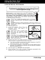
1. Turn the ignition off.
2. Locate the vehicle's 16-pin Data Link
Connector (DLC). See page 5 for
connector location.
Some DLCs have a plastic cover
that must be removed before
connecting the Scan Tool cable
connector.
If the Scan Tool is ON, turn it OFF
by pressing the POWER/LINK
button BEFORE connecting the
Scan Tool to the DLC.
3. Connect the Scan Tool cable connector to the vehicle’s DLC. The
cable connector is keyed and will only fit one way.
If you have problems connecting the cable connector to the DLC,
rotate the connector 180° and try again.
If you still have problems, check the DLC on the vehicle and on
the Scan Tool. Refer to your vehicle’s service manual to properly
check the vehicle’s DLC.
4. Turn the ignition on. DO NOT start the engine.
5. When the Scan Tool’s cable connector is properly connected to the
vehicle’s DLC, the unit automatically turns ON.
34
FixAssist™
Using the Scan Tool
CODE RETRIEVAL PROCEDURE
If the unit does not power on automatically when connected to
the vehicle’s DLC connector, it usually indicates there is no
power present at the vehicle’s DLC connector. Check your fuse
panel and replace any burned-out fuses.
If replacing the fuse(s) does not correct the problem, consult your
vehicle’s repair manual to identify the proper computer (PCM)
fuse/circuit, and perform any necessary repairs before proceeding.
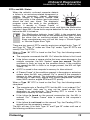
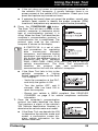
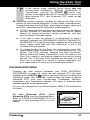
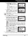
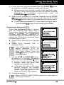
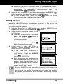
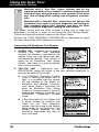
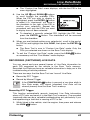
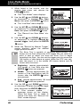
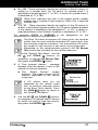
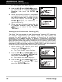
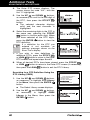
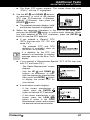
6. Press the POWER/LINK
button.
The Scan Tool will start a check of the
vehicle’s computer to determine which
type of communication protocol it is
using. When the Scan Tool identifies the
computer’s communication protocol, a
communication link is established. The
protocol type used by the vehicle’s
computer is shown on the display.
A PROTOCOL is a set of rules
and procedures for regulating
data
transmission
between
computers, and between testing
equipment and computers. As of
this writing, five different types of
protocols (ISO 9141, Keyword
2000, J1850 PWM, J1850 VPW and CAN) are in use by
vehicle manufacturers. The Scan Tool automatically
identifies
the
protocol
type and
establishes
a
communication link with the vehicle’s computer.
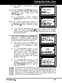
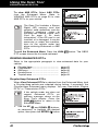
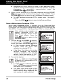
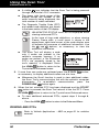
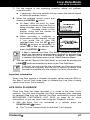
If the Scan Tool fails to link to the
vehicle’s computer a “Linking
Failed” message shows on the Scan
Tool’s display.
- Verify the connection at the DLC,
and verify the ignition is ON.
- Turn the ignition OFF, wait 5
seconds, then turn back ON to
reset the computer.
- Ensure your vehicle is OBD2 compliant. See VEHICLES
COVERED on page 5 for vehicle compliance verification
information.
7. Once the computer’s communication
protocol has been identified’ the Scan
Tool performs a check of the vehicle’s
VIN (Vehicle Identification Number) to
determine the vehicle make and model.
If the Scan Tool can decode the VIN
to determine the vehicle’s make and
model, a confirmation screen displays vehicle information for the
vehicle under test.
FixAssist™
35
Using the Scan Tool
CODE RETRIEVAL PROCEDURE
- If the vehicle information shown is correct for the vehicle
button. Proceed to step 15.
under test, press the ENTER
- If the vehicle information shown is not correct for the vehicle
button to manually select the
under test, press the LD/M
desired vehicle. The Select Vehicle screen displays. Proceed
to step 8.If the Scan Tool cannot decode the VIN to determine
the vehicle’s make and model, the Select Vehicle screen
displays. Proceed to step 8.
8. The Select Vehicle screen lists up to
three vehicles from which codes were
most recently retrieved.
To select a vehicle from the Scan
and
Tool’s memory, use the UP
buttons, as necessary, to
DOWN
highlight the desired stored vehicle,
button.
then press the ENTER
Proceed to step 15.
To retrieve codes from a new
and DOWN
vehicle, use the UP
buttons, as necessary, to
highlight New Vehicle, then press
button. The Select
the ENTER
Year screen displays.
and DOWN
buttons,
9. Use the UP
as necessary, to highlight the desired
vehicle model year, then press the
button.
ENTER
The Select Make screen displays.
and DOWN
buttons,
10. Use the UP
as necessary, to highlight the desired
vehicle make, then press the ENTER
button.
The Select Model screen displays.
and DOWN
buttons,
11. Use the UP
as necessary, to highlight the desired
vehicle model, then press the ENTER
button.
The Select Engine screen displays.
and DOWN
buttons,
12. Use the UP
as necessary, to highlight the desired
engine size, then press the ENTER
button.
36
FixAssist™
Using the Scan Tool
CODE RETRIEVAL PROCEDURE
The Select Transmission screen
displays.
13. Use the UP
and DOWN
buttons,
as necessary, to highlight the desired
transmission type, then press the
button.
ENTER
A confirmation screen displays
vehicle information for the vehicle
under test.
14. If the vehicle information shown is
correct for the vehicle under test, press
the ENTER
button. Proceed to step
15.
If the vehicle information shown is not correct for the vehicle
under test, press the LD/M
button return to the Select
Vehicle screen displays. Repeat steps 8 through 13 to re-select
the desired vehicle.
15. After approximately 10~60 seconds, the
Scan Tool will retrieve and display any
Diagnostic Trouble Codes, Monitor
Status and Freeze Frame Data retrieved
from the vehicle’s computer memory.
The Scan Tool is capable of
retrieving and storing up to 32 codes
in memory, for immediate or later
viewing.
If a recommended solution for the
"priority" DTC is available, the Fix
Assist screen for the DTC displays.
The screen shows recommended
inspection and repair actions to
correct the malfunction that caused
the DTC to be set.
If a recommended solution for the
“priority” DTC is not available, an
advisory message displays. Press
the DTC/FF
button to scroll to
the next DTC.
If more than one malfunction is present that causes more than
one DTC to be set, Fix Assist will be displayed only for the
code with the highest priority. The code designated "01" on the
Scan Tool display (see step 16 for more information) is
referred to as the PRIORITY code. The priority code is also
the one that has commanded the MIL on.
FixAssist™
37
Using the Scan Tool
CODE RETRIEVAL PROCEDURE
To view retrieved DTCs and Freeze Frame data, press the
DTC/FF
button and proceed to step 16.
16. To read the display:
Refer to DISPLAY FUNCTIONS on page 9 for a description of
display elements.
A visible
icon indicates that the Scan Tool is being powered
through the vehicle’s DLC connector.
A visible
icon indicates that the Scan Tool is linked to
(communicating with) the vehicle’s computer.
The I/M Monitor Status icons indicate the type and number of
Monitors the vehicle supports, and provides indications of the
current status of the vehicle’s Monitors. A solid Monitor icon
indicates the associated Monitor has run and completed its
testing. A blinking Monitor icon indicates the associated Monitor
has not run and completed its testing.
The upper right hand corner of the
display shows the number of the
code currently being displayed, the
total number of codes retrieved, and
whether or not the displayed code
commanded the MIL on. If the code
being displayed is a PENDING code,
the PENDING icon is shown. If the
code
being
displayed
is
a
PERMANENT code, the PERMANENT icon is shown.
The Diagnostic Trouble Code (DTC) and related code definition
are shown in the lower section of the display.
In the case of long code definitions, a small arrow is shown in the
upper/lower right-hand corner of the Scan Tool display area to
indicate the presence of additional information. Use the
and
buttons, as necessary, to view the additional information.
If a definition for the currently displayed code is not available,
an advisory message shows on the Scan Tool’s display.
The Scan Tool will display a code
only if codes are present in the
vehicle’s computer memory. If no
codes are present, the message “No
Powertrain DTCs or Freeze Frame
Data presently stored in the
vehicle’s computer. Press the DTC
button to view your Enhanced
DTC’s display. Press the DTC/FF
button to enter the “enhanced”
ENHANCED MENU on page 41).
mode
(see
THE
17. Read and interpret Diagnostic Trouble Codes/system condition
using the display and the green, yellow and red LEDs.
38
FixAssist™
Using the Scan Tool
CODE RETRIEVAL PROCEDURE
The green, yellow and red LEDs are used (with the display) as
visual aids to make it easier to determine engine system
conditions.
Green LED – Indicates that all
engine systems are “OK” and
operating normally. All monitors
supported by the vehicle have run
and performed their diagnostic
testing, and no trouble codes are
present. All Monitor icons will be
solid.
Yellow LED – Indicates one of the
following conditions:
A. A PENDING CODE IS PRESENT –
If the yellow LED is illuminated, it
may indicate a Pending code is
present. Check the Scan Tool’s
display for confirmation. A Pending
code is confirmed by the presence
of a numeric code and the word
PENDING on the Scan Tool’s
display.
B. MONITOR NOT RUN STATUS – If
the Scan Tool’s display shows a
zero (indicating there are no DTC’s
present in the vehicle’s computer
memory), but the yellow LED is
illuminated, it may be an indication
that some of the Monitors
supported by the vehicle have not
yet run and completed their
diagnostic testing. Check the Scan Tool’s display for
confirmation. All Monitor icons that are blinking have not yet
run and completed their diagnostic testing; all Monitor icons
that are solid have run and completed their diagnostic testing.
Red LED – Indicates there is a
problem with one or more of the
vehicle’s systems. The red LED is
also used to indicate that DTC(s)
are present (displayed on the Scan
Tool’s screen). In this case, the
Malfunction Indicator (Check Engine)
lamp on the vehicle’s instrument
panel will be illuminated.
DTC’s that start with “P0”, “P2” and some “P3” are considered
Generic (Universal). All Generic DTC definitions are the same
on all OBD2 equipped vehicles.
DTC’s that start with “P1” and some “P3” are Manufacturer specific
codes and their code definitions vary with each vehicle
manufacturer.
FixAssist™
39
Using the Scan Tool
CODE RETRIEVAL PROCEDURE
If the definition for the currently
displayed code is not available, an
advisory message shows on the
Scan Tool’s LCD display.
18. If more than one DTC was retrieved,
and to view Freeze Frame Data, press
and release the DTC/FF
button, as
necessary.
Each time the DTC/FF
button is pressed and released, the
Scan Tool will scroll and display the next DTC in sequence until
all DTCs in its memory have displayed.
Freeze Frame Data (if available) will display after DTC #1.
Whenever the Scroll function is used to view additional
DTCs and Freeze Frame Data, the Scan Tool's
communication link with the vehicle's computer
disconnects. To re-establish communication, press the
POWER/LINK
button again.
In OBD2 systems, when an
emissions-related engine malfunction
occurs that causes a DTC to set, a
record or snapshot of engine conditions at the time that the malfunction
occurred is also saved in the vehicle’s
computer memory. The record saved
is called Freeze Frame data. Saved
engine conditions include, but are not
limited to: engine speed, open or closed loop operation, fuel system
commands, coolant temperature, calculated load value, fuel
pressure, vehicle speed, air flow rate, and intake manifold pressure.
If more than one malfunction is present that causes more than
one DTC to be set, only the code with the highest priority will
contain Freeze Frame data. The code designated “01” on the
Scan Tool display is referred to as the PRIORITY code, and
Freeze Frame data always refers to this code. The priority
code is also the one that has commanded the MIL on.
Retrieved information can be uploaded to a Personal Computer
(PC) with the use of optional software (see instructions included
with the software for more information).
19. When the last retrieved DTC has been displayed and the DTC/FF
button is pressed, the Scan Tool enters the “enhanced” mode.
40
See THE ENHANCED MENU on page 41 for more information.
If you do not wish to view enhanced DTCs, press the LD/M
button to return to the OBD2 DTC screen.
FixAssist™
Using the Scan Tool
THE ENHANCED MENU
If the vehicle make selected during linking was not
Chrysler/Jeep, Ford/Mazda, GM/Isuzu, Honda/Acura, or
Toyota/Lexus, pressing the DTC/FF
button after
display of the last retrieved DTC returns the screen to the
first retrieved DTC (the Enhanced DTC menu is not
displayed).
20. Determine engine system(s) condition by viewing the Scan Tool’s
display for any retrieved Diagnostic Trouble Codes, code definitions,
Freeze Frame data and Live Data, interpreting the green, yellow and
red LEDs, and reviewing Fix Assist data (when supplied).
If DTC’s were retrieved and you are going to perform the repairs
yourself, proceed by consulting the Vehicle’s Service Repair
Manual for testing instructions, testing procedures, and flow
charts related to retrieved code(s).
If you plan to take the vehicle to a professional to have it
serviced, complete the PRELIMINARY VEHICLE DIAGNOSTIC
WORKSHEET on page 29 and take it together with the retrieved
codes, freeze frame data and LED information to aid in the
troubleshooting procedure.
To prolong battery life, the Scan Tool automatically shuts “Off”
approximately three minutes after it is disconnected from the
vehicle. The DTCs retrieved, captured Live Data Information,
Monitor Status and Freeze Frame data (if any) will remain in the
Scan Tool’s memory, and may be viewed at any time by turning
the unit “On”. If the Scan Tool’s batteries are removed, or if the
Scan Tool is re-linked to a vehicle to retrieve codes/data, any
prior codes/data in its memory are automatically cleared.
THE ENHANCED MENU
Following the code retrieval procedure (see CODE RETRIEVAL
PROCEDURE on page 34), when the last retrieved DTC has been
displayed and the DTC/FF
button is pressed, the Scan Tool enters the
“enhanced” mode. The “enhanced” mode provides the ability to retrieve
enhanced DTCs from most Chrysler/Jeep, Ford/Mazda, GM/Isuzu,
Honda/Acura and Toyota/Lexus vehicles. The types of enhanced data
available depends on the vehicle make.
You can also retrieve Anti-Lock Brake System (ABS) DTCs and access
Fix Assist.
To view Enhanced DTCs: Select
Enhanced DTCs from the Enhanced Menu.
Refer to VIEWING ENHANCED DTCs on
page 42 to view enhanced DTCs for your
vehicle.
FixAssist™
41
Using the Scan Tool
VIEWING ENHANCED DTCs
To view ABS DTCs: Select ABS DTCs
from the Enhanced Menu. Refer to
VIEWING ABS DTCs on page 50 to view
ABS DTCs for your vehicle.
The Scan Tool includes a Secure
Digital (SD) memory card that
contains code definitions and the
FixAssist database (refer to
Installing the Secure Digital (SD)
Card on page 6 for more
information). If the SD card is not
installed, or is damaged, it may be
necessary to select the manufacturer for the vehicle under test
when retrieving Enhanced or ABS
DTCs.
To exit the Enhanced Menu: Press the LD/M
DTC screen shows the first code retrieved.
button. The OBD2
VIEWING ENHANCED DTCs
Refer to the appropriate paragraph to view enhanced data for your
vehicle:
Chrysler/Jeep.........................................
Ford/Mazda............................................
GM/Isuzu................................................
Honda/Acura ..........................................
Toyota/Lexus .........................................
page 42
page 44
page 46
page 47
page 49
Chrysler/Jeep Enhanced DTCs
When View Enhanced DTCs is selected from the Enhanced Menu (and
a Chrysler/Jeep vehicle was selected during linking, if prompted), the
Chrysler/Jeep Enhanced menu displays. You may view either “Engine
DTCs” or “Transmission DTCs.”
If the vehicle under test does
support Enhanced DTCs,
advisory message shows on
Scan Tool’s display. Press
LD/M
button to return to
Enhanced Menu.
not
an
the
the
the
1. Use the UP
and DOWN
buttons,
as necessary, to highlight the desired
button.
option, then press the ENTER
42
FixAssist™
Using the Scan Tool
VIEWING ENHANCED DTCs
Transmission DTCs are not supported on most Chrysler/Jeep
vehicles manufactured prior to 2002.
A “One moment please” message
displays while the Scan Tool
retrieves the selected DTCs.
If the Scan Tool fails to link to the
vehicle’s computer, the message
“Unable to establish a link with the
vehicle. Verify the ignition is ON.”
shows on the Scan Tool’s display.
2. To read the display:
Refer to DISPLAY FUNCTIONS on page 9 for a description of
LCD display elements.
A visible
icon indicates that the Scan Tool is being powered
through the vehicle’s DLC connector.
The upper right hand corner of the
display shows the number of the
code currently being displayed, the
total number of codes retrieved.
The Diagnostic Trouble Code (DTC)
and related code definition are shown
in the lower section of the LCD display.
I/M MONITOR STATUS icons are not displayed when
viewing enhanced DTCs.
In the case of long code definitions, or when viewing
Freeze Frame data, a small arrow is shown in the
upper/lower right-hand corner of the code display area
to indicate the presence of additional information. Use
the
and
buttons, as necessary, to view the
additional information.
The Scan Tool will display a code only
if codes are present in the vehicle’s
computer memory. If no codes are
present, a “No Enhanced DTC’s are
presently stored in the vehicle’s
computer” is displayed. Press the
button to return to the
LD/M
Chrysler/Jeep Enhanced menu.
3. If more than one code was retrieved press the DTC/FF
as necessary, to display additional codes one at a time.
button,
Whenever the Scroll function is used to view additional codes,
the Scan Tool’s communication link with the vehicle’s computer
disconnects. To re-establish communication, press the
button again.
POWER/LINK
FixAssist™
43
Using the Scan Tool
VIEWING ENHANCED DTCs
4. When the last retrieved DTC has been displayed and the DTC/FF
button is pressed, the Scan Tool returns to the first DTC. Press
button to return to the Chrysler/Jeep Enhanced menu.
the LD/M
To view additional enhanced DTCs, repeat steps 1 through 4, above.
- Press the LD/M
button to return to the Enhanced Menu.
Ford/Mazda Enhanced DTCs
Mazda Enhanced DTCs are available for Mazda-branded
Ford vehicles only.
When View Enhanced DTCs is selected from the Enhanced Menu (and
a Ford/Mazda vehicle was selected during linking, if prompted), the
Ford/Mazda Enhanced menu displays. You may view DTCs for either
the “Continuous Memory Test”, “KOEO (Key On Engine Off) Test” or
“KOER (Key On Engine Running) Test.”
If the vehicle under test does
support Enhanced DTCs,
advisory message shows on
Scan Tool’s display. Press
LD/M
button to return to
Enhanced Menu.
not
an
the
the
the
1. Use the UP
and DOWN
buttons,
as necessary, to highlight the desired
button.
option, then press the ENTER
When choosing to view KOER
Test DTCs, start the vehicle’s
engine before making your
selection.
If the KOER Test was selected, and
the vehicle’s engine is not running,
an advisory message shows on the
Scan Tool’s display.
- Press the LD/M
button to
return to the Ford/Mazda Enhanced
menu.
2. An “instructional” message shows on
the Scan Tool’s display. Perform test
procedures as appropriate.
44
If the Continuous Memory or KOEO
test was selected, turn the ignition
OFF, then back ON. Press the
button to start the test.
ENTER
- A “One moment please” message
displays while the test is in progress.
FixAssist™
Using the Scan Tool
VIEWING ENHANCED DTCs
If the KOER test was selected, press
button to continue.
the ENTER
- A “One moment please” message
displays while the test is in
progress.
- Turn the steering wheel to the
right, then release.
- Press and release the brake pedal.
- Cycle the overdrive switch (if
equipped).
If the Scan Tool fails to link to the
vehicle’s computer, the message
“Unable to establish a link with the
vehicle. Verify the ignition is ON.”
shows on the Scan Tool’s display.
3. To read the display:
Refer to DISPLAY FUNCTIONS on page 9 for a description of
LCD display elements.
A visible
icon indicates that the Scan Tool is being powered
through the vehicle’s DLC connector.
The upper right hand corner of the
display shows the number of the
code currently being displayed, the
total number of codes retrieved.
The Diagnostic Trouble Code (DTC)
and related code definition are shown
in the lower section of the LCD display.
I/M MONITOR STATUS icons are not displayed when
viewing enhanced DTCs.
In the case of long code definitions, or when viewing
Freeze Frame data, a small arrow is shown in the
upper/lower right-hand corner of the code display area
to indicate the presence of additional information. Use
the
and
buttons, as necessary, to view the
additional information.
The Scan Tool will display a code
only if codes are present in the
vehicle’s computer memory. If no
codes are present, a “No Enhanced
DTC’s are presently stored in the
tool’s memory” is displayed. Press
button to return to the
the LD/M
Ford/Mazda Enhanced menu.
4. If more than one code was retrieved press the DTC/FF
as necessary, to display additional codes one at a time.
FixAssist™
button,
45
Using the Scan Tool
VIEWING ENHANCED DTCs
Whenever the Scroll function is used to view additional codes,
the Scan Tool’s communication link with the vehicle’s computer
disconnects. To re-establish communication, press the
button again.
POWER/LINK
5. When the last retrieved DTC has been displayed and the DTC/FF
button is pressed, the Scan Tool returns to the first DTC. Press
button to return to the Ford/Mazda Enhanced menu.
the LD/M
To view additional enhanced DTCs, repeat steps 1 through 5,
above.
- Press the LD/M
button to return to the Enhanced Menu.
General Motors/Isuzu Enhanced DTCs
When View Enhanced DTCs is selected from the Enhanced Main
Menu (and a General Motors/Isuzu vehicle was selected during linking,
if prompted), the GM/Isuzu Enhanced menu displays. You may view the
“MIL DTCs”, “Current DTCs”, “Fail Since Clear DTCs” or “History DTCs.”
If the vehicle under test does
support Enhanced DTCs,
advisory message shows on
Scan Tool’s display. Press
LD/M
button to return to
Enhanced Menu.
not
an
the
the
the
1. Use the UP
and DOWN
buttons,
as necessary, to highlight the desired
button.
option, then press the ENTER
A “One moment please” message
displays while the Scan Tool
retrieves the selected DTCs.
If the Scan Tool fails to link to the
vehicle’s computer, the message
“Unable to establish a link with the
vehicle. Verify the ignition is ON.”
shows on the Scan Tool’s display.
2. To read the display:
Refer to DISPLAY FUNCTIONS
on page 9 for a description of LCD
display elements.
46
A visible
icon indicates that the
Scan Tool is being powered through
the vehicle’s DLC connector.
The upper right hand corner of the
display shows the number of the
code currently being displayed, the
total number of codes retrieved.
FixAssist™
Using the Scan Tool
VIEWING ENHANCED DTCs
The Diagnostic Trouble Code (DTC) and related code definition
are shown in the lower section of the LCD display.
I/M MONITOR STATUS icons are not displayed when
viewing enhanced DTCs.
In the case of long code definitions, or when viewing
Freeze Frame data, a small arrow is shown in the
upper/lower right-hand corner of the code display area
to indicate the presence of additional information. Use
the
and
buttons, as necessary, to view the
additional information.
The Scan Tool will display a code
only if codes are present in the
vehicle’s computer memory. If no
codes are present, a “No Enhanced
DTC’s are presently stored in the
tool’s memory” is displayed. Press
button to return to
the DTC/FF
the GM Enhanced menu.
3. If more than one code was retrieved press the DTC/FF
as necessary, to display additional codes one at a time.
button,
Whenever the Scroll function is used to view additional codes,
the Scan Tool’s communication link with the vehicle’s computer
disconnects. To re-establish communication, press the
button again.
POWER/LINK
4. When the last retrieved DTC has been displayed and the DTC/FF
button is pressed, the Scan Tool returns to the first DTC. Press
button to return to the GM/Isuzu Enhanced menu.
the LD/M
To view additional enhanced DTCs, repeat steps 1 through 4,
above.
- Press the LD/M
button to return to the Enhanced Menu.
Honda/Acura Enhanced DTCs
When View Enhanced DTCs is selected
from the Enhanced Main Menu (and a
Honda/Acura vehicle was selected during
linking, if prompted), the Honda Acura
Enhanced menu displays. Depending on the
protocol used to communicate with your
vehicle, the Honda/Acura Enhanced menu
provides options to view:
Permanent DTCs or Temporary DTCs
Confirmed DTCs or Pending DTCs
FixAssist™
47
Using the Scan Tool
VIEWING ENHANCED DTCs
If the vehicle under test does
support Enhanced DTCs,
advisory message shows on
Scan Tool’s display. Press
button to return to
LD/M
Enhanced Menu.
not
an
the
the
the
and DOWN
buttons, as necessary, to highlight
1. Use the UP
button.
the desired option, then press the ENTER
A “One moment please” message
displays while the Scan Tool
retrieves the selected DTCs.
If the Scan Tool fails to link to the
vehicle’s computer, the message
“Unable to establish a link with the
vehicle. Verify the ignition is ON.”
shows on the Scan Tool’s display.
2. To read the display:
Refer to DISPLAY FUNCTIONS on page 9 for a description of
LCD display elements.
A visible
icon indicates that the Scan Tool is being powered
through the vehicle’s DLC connector.
The upper right hand corner of the
display shows the number of the
code currently being displayed, the
total number of codes retrieved.
The Diagnostic Trouble Code (DTC)
and related code definition are
shown in the lower section of the
LCD display.
I/M MONITOR STATUS icons are not displayed when
viewing enhanced DTCs.
In the case of long code definitions, or when viewing
Freeze Frame data, a small arrow is shown in the
upper/lower right-hand corner of the code display area
to indicate the presence of additional information. Use
the
and
buttons, as necessary, to view the
additional information.
48
The Scan Tool will display a code only
if codes are present in the vehicle’s
computer memory. If no codes are
present, a “No Enhanced DTC’s are
presently stored in the vehicle’s
computer” is displayed. Press the
button to return to the
LD/M
Honda/Acura Enhanced menu.
FixAssist™
Using the Scan Tool
VIEWING ENHANCED DTCs
3. If more than one code was retrieved press the DTC/FF
as necessary, to display additional codes one at a time.
button,
Whenever the Scroll function is used to view additional codes,
the Scan Tool’s communication link with the vehicle’s computer
disconnects. To re-establish communication, press the
POWER/LINK
button again.
4. When the last retrieved DTC has been displayed and the DTC/FF
button is pressed, the Scan Tool returns to the first DTC. Press
button to return to the Honda/Acura Enhanced menu.
the LD/M
To view additional enhanced DTCs, repeat steps 1 through 4, above.
- Press the LD/M
button to return to the Enhanced Menu.
Toyota/Lexus Enhanced DTCs
When View Enhanced DTCs is selected
from the Enhanced Main Menu (and a
Toyota/Lexus vehicle was selected during
linking, if prompted), the Toyota/Lexus
Enhanced menu displays. Depending on
the protocol used to communicate with your
vehicle, the Toyota/Lexus Enhanced menu
provides options to view:
Current DTCs, History DTCs or Pending
DTCs
Current DTCs, Historical DTCs or
Readiness DTCs
If the vehicle under test does not
support Enhanced DTCs, an
advisory message shows on the
Scan Tool’s display. Press the
LD/M
button to return to the
Enhanced Menu.
1. Use the UP
and DOWN
buttons,
as necessary, to highlight the desired
option, then press the ENTER
button.
A “One moment please” message
displays, while the Scan Tool
retrieves the selected DTCs.
If the Scan Tool fails to link to the
vehicle’s computer, the message
“Unable to establish a link with the
vehicle. Verify the ignition is ON.”
shows on the Scan Tool’s display.
2. To read the display:
Refer to DISPLAY FUNCTIONS on page 9 for a description of
LCD display elements.
FixAssist™
49
Using the Scan Tool
VIEWING ABS DTCs
A visible
icon indicates that the Scan Tool is being powered
through the vehicle’s DLC connector.
The upper right hand corner of the
display shows the number of the
code currently being displayed, the
total number of codes retrieved.
The Diagnostic Trouble Code (DTC)
and related code definition are shown
in the lower section of the LCD display.
I/M MONITOR STATUS icons are not displayed when
viewing enhanced DTCs.
In the case of long code definitions, or when viewing
Freeze Frame data, a small arrow is shown in the
upper/lower right-hand corner of the code display area
to indicate the presence of additional information. Use
the
and
buttons, as necessary, to view the
additional information.
The Scan Tool will display a code
only if codes are present in the
vehicle’s computer memory. If no
codes are present, a “No Enhanced
DTC’s are presently stored in the
tool’s memory” is displayed. Press
the LD/M
button to return to the
Toyota/Lexus Enhanced menu.
3. If more than one code was retrieved press the DTC/FF
as necessary, to display additional codes one at a time.
button,
Whenever the Scroll function is used to view additional codes,
the Scan Tool’s communication link with the vehicle’s computer
disconnects. To re-establish communication, press the
button again.
POWER/LINK
4. When the last retrieved DTC has been displayed and the DTC/FF
button is pressed, the Scan Tool returns to the first DTC. Press
button to return to the Toyota/Lexus Enhanced menu.
the LD/M
To view additional enhanced DTCs, repeat steps 1 through 4,
above.
- Press the LD/M
button to return to the Enhanced Menu.
VIEWING ABS DTCs
Refer to Vehicle Applications - ABS on page 91 for vehicles
covered.
50
FixAssist™
Using the Scan Tool
VIEWING ABS DTCs
Reading ABS DTCs
1. When View ABS DTCs is selected from
the Enhanced Main Menu, The Scan
Tool starts a check of the vehicle’s
computer to determine which type of
communication protocol it is using.
2. A "One moment please" message
displays while the Scan Tool retrieves
the selected DTCs.
If the Scan Tool fails to link to the
vehicle’s computer, the message
“Unable to establish a link with the
vehicle. Verify the ignition is ON.”
shows on the Scan Tool’s display.
If the vehicle does not support ABS
communication, an advisory message
shows on the Scan Tool’s display.
button to return
Press the LD/M
to the Enhanced Main Menu.
If a recommended solution for the
"priority" DTC is available, the Fix
Assist screen for the DTC displays.
The screen shows recommended
inspection and repair actions to
correct the malfunction that caused
the DTC to be set.
If more than one malfunction is present that causes more than
one DTC to be set ,Fix Assist will be displayed only for the
code with the highest priority. The code designated "01" on the
Scan Tool display (see step 3 for more information) is referred
to as the PRIORITY code.
Fix Assist is available for "current" DTCs only. Fix Assist is not
available for "history" DTCs.
To view retrieved DTCs, press the DTC/FF
proceed to step 3.
To view additional information related to the recommended
button.
solution, press the ENTER
FixAssist™
button and
51
Using the Scan Tool
VIEWING ABS DTCs
-
When the ENTER
button is
pressed from the Fix Assist
screen, or when a recommended
solution is not available for the
"priority" code, an information
screen displays. The screen lists
additional sources for obtaining a
recommended
solution
and
related data for the priority code.
-
To view retrieved DTCs, press the DTC/FF
proceed to step 3.
button and
3. To read the display:
Refer to DISPLAY FUNCTIONS on page 9 for a description of
LCD display elements.
A visible
icon indicates that the
Scan Tool is being powered through
the vehicle’s DLC connector.
A visible
icon indicates that the
Scan Tool is linked to (communicating
with) the vehicle’s computer.
The upper right hand corner of the display shows the number of
the code currently being displayed, the total number of codes
retrieved.
The Diagnostic Trouble Code (DTC) and related code definition
are shown in the lower section of the LCD display.
I/M MONITOR STATUS icons are not displayed when viewing
ABS DTCs.
In the case of long code definitions, a small arrow is shown in
the upper/lower right-hand corner of the code display area to
indicate the presence of additional information. Use the UP
buttons, as necessary, to view the additional
and DOWN
information.
The Scan Tool will display a code
only if codes are present in the
vehicle’s computer memory. If no
codes are present, a "No ABS DTC’s
are presently stored in the tool’s
memory" is displayed. Press the LD/M
button to return to the Test
Modes Menu.
4. If more than one code was retrieved press the DTC/FF
as necessary, to display additional codes one at a time.
52
button,
FixAssist™
Using the Scan Tool
VIEWING ABS DTCs
Whenever the Scroll function is used to view additional codes,
the Scan Tool’s communication link with the vehicle’s computer
disconnects. To re-establish communication, press the
button again.
POWER/LINK
5. When the last retrieved DTC has been displayed and the DTC/FF
button is pressed, the Scan Tool returns to the ABS Menu.
To exit the ABS mode, press the LD/M
Tool returns to the Enhanced Main Menu.
button. The Scan
Erasing ABS DTCs
If you plan to take the vehicle to a Service Center for repair, DO NOT
erase the ABS DTCs from the vehicle’s computer. If the codes are
erased, valuable information that might help the technician troubleshoot
the problem will be erased.
1. With the Scan Tool in ”ABS Mode” (see Reading ABS DTCs on
button.
page 51 for details), press the ERASE
2. A confirmation message shows on the
LCD display.
If you are sure you want to proceed,
press the ERASE
button to
erase the ABS DTCs from the
vehicle’s computer.
If you do not want to continue with the
erase process, press the LD/M
button to exit the erase mode.
3. If you chose to erase ABS DTCs, a
progress screen displays while the
erase function is in progress.
If the erase was successful, a
confirmation message shows on the
LCD display. Press the POWER/
LINK
button to return to view
the current ABS DTCs.
If the erase was not successful, an
advisory message shows on the LCD
display. Verify that the Scan Tool is
properly connected to the vehicle’s
DLC and that the ignition is on, then
repeat steps 2 and 3, above.
Erasing ABS DTCs does not fix the problem(s) that caused the
code(s) to be set. If proper repairs to correct the problem(s)
that caused the code(s) to be set are not made, the code(s)
will appear again as soon as the vehicle is driven long enough
for the problem to recur.
FixAssist™
53
Using the Scan Tool
ERASING DIAGNOSTIC TROUBLE CODES (DTCs)
ERASING DIAGNOSTIC TROUBLE CODES (DTCs)
When the Scan Tool’s ERASE function is used to erase
DTCs from the vehicle's on-board computer, "Freeze
Frame" data and manufacturer-specific enhanced data are
also erased.
If you plan to take the vehicle to a Service Center for repair, DO NOT
erase the codes from the vehicle's computer. If the codes are erased,
valuable information that might help the technician troubleshoot the
problem will also be erased.
Erase DTCs from the computer's memory as follows:
When DTCs are erased from the vehicle's computer memory,
the I/M Readiness Monitor Status program resets the status of
all Monitors to a not run "flashing" condition. To set all of the
Monitors to a DONE status, an OBD2 Drive Cycle must be
performed. Refer to your vehicle's service manual for
information on how to perform an OBD2 Drive Cycle for the
vehicle under test.
The Scan Tool must be connected
to the vehicle’s DLC to erase the
codes from the computer’s memory.
If you press the ERASE
button
when the Scan Tool is not
connected to the vehicle’s DLC, the
erase instruction screen displays.
1. If not connected already, connect the Scan Tool to the vehicle's DLC,
and turn the ignition "On.” (If the Scan Tool is already connected
and linked to the vehicle's computer, proceed directly to step 4. If
not, continue to step 2.)
2. Perform the Code Retrieval procedure
(see CODE RETRIEVAL PROCEDURE
on page 34). Wait until the codes are
displayed on the Scan Tool's display.
To erase OBD2 DTCs, proceed to
step 4.
To
erase
"enhanced"
proceed to step 3.
DTCs,
button, as
3. Press the DTC/FF
necessary, until all OBD2 codes have
been shown and the Enhanced Main
and
Menu displays. Use the UP
buttons, as necessary, to highlight View Enhanced
DOWN
button.
DTCs, then press the ENTER
54
Perform the appropriate Code Retrieval procedure (see
VIEWING ENHANCED DTCs on page 42). Wait until the codes
are displayed on the Scan Tool's display.
FixAssist™
Using the Scan Tool
I/M READINESS TESTING
Proceed to step 4.
4. Press and release the ERASE
shows on the display.
button. A confirmation message
To erase OBD2 DTCs:
-
If you are sure you want to
proceed, press the ERASE
button to erase DTCs from the
vehicle's computer.
-
If you do not want to continue
with the erase process, press
the LD/M
button to exit the
erase mode.
To erase "enhanced" DTCs:
-
If you are sure you want to
proceed, press the ERASE
button to erase DTCs from the
vehicle's computer.
-
If you do not want to continue
with the erase process, press
the LD/M
button to exit the
erase mode.
5. If you chose to erase DTCs, a progress
screen displays while the erase function
is in progress.
If the erase was successful, a
confirmation message shows on the
display. Press the POWER/LINK
button to return to the DTC
screen.
If the erase was not successful, an
advisory message shows on the
display. Verify that the Scan Tool is
properly connected to the vehicle’s
DLC and that the ignition is on, then
repeat steps 2 and 3, above.
Erasing DTCs does not fix the problem(s) that caused the
code(s) to be set. If proper repairs to correct the problem that
caused the code(s) to be set are not made, the code(s) will
appear again (and the check engine light will illuminate) as
soon as the vehicle is driven long enough for its Monitors to
complete their testing.
FixAssist™
55
Using the Scan Tool
I/M READINESS TESTING
I/M READINESS TESTING
I/M is an Inspection and Maintenance program legislated by the
Government to meet federal clean-air standards.
The program requires that a vehicle be taken periodically to an
Emissions Station for an "Emissions Test" or "Smog Check,” where the
emissions-related components and systems are inspected and tested
for proper operation. Emissions Tests are generally performed once a
year, or once every two years.
On OBD2 systems, the I/M program is enhanced by requiring vehicles
to meet stricter test standards. One of the tests instituted by the Federal
Government is called I/M 240. On I/M 240, the vehicle under test is
driven under different speeds and load conditions on a dynamometer for
240 seconds, while the vehicle's emissions are measured.
Emissions tests vary depending on the geographic or regional
area in which the vehicle is registered. If the vehicle is
registered in a highly urbanized area, the I/M 240 is probably
the type of test required. If the vehicle is registered in a rural
area, the stricter “dynamometer type” test may not be required.
I/M Readiness Monitors
I/M Readiness shows whether the various emissions-related systems on
the vehicle are operating properly and are ready for Inspection and
Maintenance testing.
State and Federal Governments enacted Regulations, Procedures and
Emission Standards to ensure that all emissions-related components
and systems are continuously or periodically monitored, tested and
diagnosed whenever the vehicle is in operation. It also requires vehicle
manufacturers to automatically detect and report any problems or faults
that may increase the vehicle's emissions to an unacceptable level.
The vehicle's emissions control system consists of several components
or sub-systems (Oxygen Sensor, Catalytic Converter, EGR, Fuel
System, etc.) that aid in reducing vehicle emissions.
To have an efficient Vehicle Emission Control System, all the emissionsrelated components and systems must work correctly whenever the
vehicle is in operation.
To comply with State and Federal Government regulations, vehicle
manufacturers designed a series of special computer programs called
"Monitors" that are programmed into the vehicle's computer. Each of these
Monitors is specifically designed to run tests and diagnostics on a specific
emissions-related component or system (Oxygen Sensor, Catalytic
Converter, EGR Valve, Fuel System, etc.) to ensure their proper operation.
Currently, there are a maximum of eleven Monitors available for use.
Each Monitor has a specific function to test and diagnose only
its designated emissions-related component or system. The
names of the Monitors (Oxygen Sensor Monitor, Catalyst
Monitor, EGR Monitor, Misfire Monitor, etc.) describe which
component or system each Monitor is designed to test and
diagnose.
56
FixAssist™
Using the Scan Tool
I/M READINESS TESTING
Emissions Inspection and Maintenance (I/M) Readiness
Monitor Status Information
I/M Readiness Monitor Status shows which of the vehicle's Monitors
have run and completed their diagnosis and testing, and which ones
have not yet run and completed testing and diagnosis of their
designated sections of the vehicle's emissions system.
If a Monitor was able to meet all the conditions required to enable it
to perform the self-diagnosis and testing of its assigned engine
system, it means the monitor "HAS RUN.”
If a Monitor has not yet met all the conditions required for it to
perform the self-diagnosis and testing of its assigned engine system;
it means the Monitor "HAS NOT RUN.”
The Monitor Run/Not Run status does not show whether
or not a problem exists in a system. Monitor status only
indicates whether a particular Monitor has or has not run
and performed the self-diagnosis and testing of its
associated system.
Performing I/M Readiness Quick Check
When a vehicle first comes from the factory, all Monitors
indicate a “HAVE RUN” status. This indicates that all Monitors
have run and completed their diagnostic testing. The “HAVE
RUN” status remains in the computer's memory, unless the
Diagnostic Trouble Codes are erased or the vehicle's
computer memory is cleared.
The Scan Tool allows you to retrieve Monitor/System Status Information
to help you determine if the vehicle is ready for an Emissions Test
(Smog Check). In addition to retrieving Diagnostic Trouble Codes, the
Scan Tool also retrieves Monitor Run/Not Run status. This information is
very important since different areas of the state/country have different
emissions laws and regulations concerning Monitor Run/Not Run status.
Before an Emissions Test (Smog Check) can be performed, your
vehicle must meet certain rules, requirements and procedures legislated
by the Federal and state (country) governments where you live.
1. In most areas, one of the requirements that must be met before a
vehicle is allowed to be Emissions Tested (Smog Checked) is that
the vehicle does not have any Diagnostic Trouble Codes present
(with the exception of PENDING Diagnostic Trouble Codes).
2. In addition to the requirement that no Diagnostic Trouble Codes be
present, some areas also require that all the Monitors that a
particular vehicle supports indicate a "Has Run" status condition
before an Emissions Check may be performed.
3. Other areas may only require that some (but not all) Monitors
indicate a "Has Run" status before an Emissions Test (Smog Check)
may be performed.
FixAssist™
57
Using the Scan Tool
I/M READINESS TESTING
Monitors with a "Has Run" status indicate that all the
required conditions they needed to perform diagnosis and
testing of their assigned engine area (system) have been
met, and all diagnostic testing has completed successfully.
Monitors with a "Has Not Run" status have not yet met the
conditions they need to perform diagnosis and testing of
their assigned engine area (system), and have not been
able to perform diagnostic testing on that system.
The green, yellow and red LEDs provide a quick way to help you
determine if a vehicle is ready for an Emissions Test (Smog Check).
Follow the instructions below to perform the Quick Check.
Perform the CODE RETRIEVAL PROCEDURE as described on page
34, then interpret the LED indications as follows:
Interpreting I/M Readiness Test Results
1. GREEN LED - Indicates that all engine
systems are "OK" and operating
normally (all Monitors supported by the
vehicle have run and performed their
self-diagnostic testing). The vehicle is
ready for an Emissions Test (Smog
Check), and there is a good possibility
that it can be certified.
2. YELLOW LED - Determine from the CODE RETRIEVAL
PROCEDURE (page 34) which of the two possible conditions is
causing the yellow LED to light.
58
If a "PENDING" Diagnostic Trouble
Code is causing the yellow LED to
light, it is possible that the vehicle
will be allowed to be tested for
emissions and certified. Currently,
most areas (states / countries) will
allow an Emissions Test (Smog
Check) to be performed if the only
code in the vehicle's computer is a
"PENDING" Diagnostic Trouble
Code.
If the illumination of the Yellow LED
is being caused by monitors that
“have not run” their diagnostic
testing, then the issue of the vehicle
being ready for an Emissions Test
(Smog Check) depends on the
emissions regulations and laws of
your local area.
FixAssist™
Using the Scan Tool
I/M READINESS TESTING
- Some areas require that all Monitors indicate a "Has Run"
status before they allow an Emissions Test (Smog Check) to
be performed. Other areas only require that some, but not all,
Monitors have run their self-diagnostic testing before an
Emissions Test (Smog Check) may be performed.
- From the code retrieval procedure, determine the status of
each Monitor (a solid Monitor icon shows Monitor "Has Run"
status, a flashing Monitor icon indicates "Has Not Run" status).
Take this information to an emissions professional to
determine (based on your test results) if your vehicle is ready
for an Emissions Test (Smog Check).
3. RED LED - Indicates there is a problem
with one or more of the vehicle's
systems. A vehicle displaying a red LED
is definitely not ready for an Emissions
Test (Smog Check). The red LED is
also an indication that there are
Diagnostic Trouble Code(s) present
(displayed on the Scan Tool's screen).
The Malfunction Indicator (Check
Engine) Lamp on the vehicle's
instrument panel will light steady. The problem that is causing the
red LED to light must be repaired before an Emissions Test (Smog
Check) can be performed. It is also suggested that the vehicle be
inspected/repaired before driving the vehicle further.
If the Red LED was obtained, there is a definite problem present in
the system(s). In these cases, you have the following options.
Repair the vehicle yourself. If you are going to perform the
repairs yourself, proceed by reading the vehicle service manual
and following all its procedures and recommendations.
Take the vehicle to a professional to have it serviced. The
problem(s) causing the red LED to light must be repaired before
the vehicle is ready for an Emissions Test (Smog Check).
Using the I/M Readiness Monitor Status to Confirm a Repair
The I/M Readiness Monitor Status function can be used (after repair of a
fault has been performed) to confirm that the repair has been performed
correctly, and/or to check for Monitor Run Status. Use the following
procedure to determine I/M Readiness Monitor Status:
1. Using retrieved Diagnostic Trouble Codes (DTCs) and code
definitions as a guide, and following manufacturer's repair
procedures, repair the fault or faults as instructed.
2. After the fault or faults have been repaired, connect the Scan Tool to
the vehicle's DLC and erase the code or codes from the vehicle's
computer memory.
See page 54 for procedures for ERASING DIAGNOSTIC
TROUBLE CODES (DTCs) from the vehicle's on-board
computer.
FixAssist™
59
Using the Scan Tool
I/M READINESS TESTING
Write the codes down on a piece of paper for reference before
erasing.
3. After the erase procedure is performed, most of the Monitor icons on
the Scan Tool’s display will be flashing. Leave the Scan Tool
connected to the vehicle, and perform a Trip Drive Cycle for each
"flashing" Monitor:
Misfire, Fuel and Comprehensive Component Monitors run
continuously and their icons will always be on solid, even after
the erase function is performed.
Each DTC is associated with a specific Monitor. Consult the
vehicle's service manual to identify the Monitor (or Monitors)
associated with the faults that were repaired. Follow the
manufacturer's procedures to perform a Trip Drive Cycle for the
appropriate Monitors.
While observing the Monitor icons on the Scan Tool’s display,
perform a Trip Drive Cycle for the appropriate Monitor or
Monitors.
If the vehicle needs to be driven in order to perform a Trip
Drive Cycle, ALWAYS have a second person help you.
One person should drive the vehicle while the other
person observes the Monitor icons on the Scan Tool for
Monitor RUN status. Trying to drive and observe the Scan
Tool at the same time is dangerous, and could cause a
serious traffic accident.
4. When a Monitor's Trip Drive Cycle is performed properly, the Monitor
icon on the Scan Tool’s display changes from "flashing" to "solid,”
indicating that the Monitor has run and finished its diagnostic testing.
60
If, after the Monitor has run, the MIL on the vehicle's dash is not lit, and
no stored or pending codes associated with that particular Monitor are
present in the vehicle's computer, the repair was successful.
If, after the Monitor has run, the MIL on the vehicle's dash lights
and/or a DTC associated with that Monitor is present in the
vehicle's computer, the repair was unsuccessful. Refer to the
vehicle's service manual and recheck repair procedures.
FixAssist™
Live Data Mode
VIEWING LIVE DATA
The OBD2 Scan Tool is a special diagnostic tool that communicates
with the vehicle's computer. The Scan Tool lets you view and/or
"capture" (record) "real-time" Live Data. This information includes values
(volts, rpm, temperature, speed etc.) and system status information
(open loop, closed loop, fuel system status, etc.) generated by the
various vehicle sensors, switches and actuators.
In effect the Scan Tool lets you view, in "real time", the same signal
values generated by the sensors, actuators, switches and/or vehicle
system status information used by the vehicle's computer when
calculating and conducting system adjustments and corrections.
The real time (Live Data) vehicle operating information (values/status)
that the computer supplies to the Scan Tool for each sensor, actuator,
switch, etc. is called Parameter Identification (PID) Data.
Each PID (sensor, actuator switch, status, etc.) has a set of operating
characteristics and features (parameters) that serve to identify it. The
Scan Tool displays this information for each sensor, actuator, switch or
status that is supported by the vehicle under test.
WARNING: If the vehicle must be driven in order to perform a
troubleshooting procedure, ALWAYS have a second person
help you. One person should drive the vehicle while the other
person observes the Scan Tool data. Trying to drive and
operate the Scan Tool at the same time is dangerous, and
could cause a serious traffic accident.
VIEWING LIVE DATA
1. While linked to the vehicle, start the
engine, then press and release the
button.
LD/M
The “Test Modes” menu displays.
and DOWN
buttons,
2. Use the UP
as necessary, to highlight View Live
button.
Data, then press the ENTER
3. Real-time Live Data (PID) information
supported by the vehicle under test
displays.
Remember, what you are viewing
is "real-time" Live Data. The
values (volts, rpm, temperature,
vehicle speed, system status etc)
for the various PIDS displayed
may change as the vehicle's
operating conditions change.
4. A vehicle usually supports several PIDs, however, only a limited
amount of PID data can be displayed on the screen at one time. If
additional PID data is available, a small arrow will be shown on the
display. Use the the UP
and DOWN
buttons, as necessary,
to scroll up or down to view all available PID data.
FixAssist™
61
Live Data Mode
CUSTOMIZING LIVE DATA (PIDs)
If communication with the vehicle is
lost while viewing Live Data, a
Communication Lost" message
shows on the Scan Tool's display.
5. Press and release the ENTER
button
to view the currently selected PID in
“graph” mode. Press and release the
button again to return to the
ENTER
PID list.
6. Press and hold the ENTER
button to
view the “expanded” definition for the
currently selected PID. Press and release
button again to return to
the ENTER
the PID list.
7. If you experience vehicle problems,
view and/or compare the Live Data (PID)
information displayed on the Scan Tool
to specifications in the vehicle's repair
manual.
If desired, you can "customize" the
Live Data display to show only those
PIDs you are interested in viewing.
See Customizing Live Data (PIDs)
below for details. You may also choose to "capture" (record) Live
Data for later viewing. See RECORDING (CAPTURING) LIVE
DATA on page 63 for details.
CUSTOMIZING LIVE DATA (PIDs)
This feature lets you customize the Scan Tool display to show only
those PIDs that are of interest at the current time. You can customize
the Live Data display by placing the Scan Tool in "Custom Live Data"
mode and selecting only the PIDs that you wish to display. To customize
the Live Data display, proceed as follows:
1. While linked to the vehicle, start the
engine, then press and release the
LD/M
button.
The “Test Modes” menu displays.
and DOWN
buttons,
2. Use the UP
as necessary, to highlight Live Data
button.
Menu, then press the ENTER
The “Live Data” menu displays.
and DOWN
buttons,
3. Use the UP
as necessary, to highlight Custom Live
button.
Data, then press the ENTER
62
FixAssist™
Live Data Mode
RECORDING (CAPTURING) LIVE DATA
The "Custom Live Data" menu displays, with the first PID in the
menu highlighted.
4. Use the UP
and DOWN
buttons
to scroll through the available PIDs.
When the PID you wish to display is
button
highlighted, press the ENTER
to select it (a "checkmark" will show in
the checkbox to the right of the PID to
confirm your selection). Repeat the
procedure until only the PIDs you want
to display have all been selected.
To deselect a currently selected PID, highlight the PID, then
button. The checkmark will be removed
press the ENTER
from the checkbox.
5. When you are finished making your selection(s), scroll to the end of
the PID list and highlight the word DONE, then press the ENTER
button.
The Scan Tool is now in "Custom Live Data" mode. Only the
PIDs you selected are shown on the Scan Tools display.
6. To exit the "Custom Live Data" mode, press the LD/M
as necessary until the “Test Modes” menu displays.
button
RECORDING (CAPTURING) LIVE DATA
You can record and save several frames of Live Data information for
each PID supported by the vehicle in the Scan Tool's memory.
Recorded Live Data can serve as valuable information to help you in the
troubleshooting of vehicle problems.
There are two ways that the Scan Tool can "record" Live Data:
Record by DTC Trigger
Record by Manual Trigger
button is pressed at any time while in
If the POWER/LINK
Live Data mode, any stored (recorded) Live Data will be
cleared (erased) from the Scan Tool’s memory.
Record by DTC Trigger
This function automatically records (captures) Live Data information
when a DTC sets and saves it in the Scan Tool’s memory. The recorded
(captured) data can be a valuable troubleshooting aid, particularly if you
are experiencing a fault that is causing a DTC to set.
1. While linked to the vehicle, start the engine, then press and release
the LD/M
button.
FixAssist™
63
Live Data Mode
RECORDING (CAPTURING) LIVE DATA
The “Test Modes” menu displays.
and DOWN
buttons,
2. Use the UP
as necessary, to highlight Live Data
Menu, then press the ENTER
button.
The “Live Data” menu displays.
and DOWN
buttons,
3. Use the UP
as necessary, to highlight Record Live
button.
Data, then press the ENTER
The "Record Live Data Menu" displays.
4. Use the UP
and DOWN
buttons,
as necessary, to highlight Record by
DTC trigger, then press the ENTER
button.
If DTCs are presently stored in the
vehicle’s computer, an advisory
message displays. Use the UP
buttons, as
and DOWN
necessary, to highlight Erase DTCs,
button to
then press the ENTER
erase DTCs from the vehicle’s
computer. When the Erase process
is complete, the “Record by DTC
Trigger” screen displays.
5. When the "Record by DTC Trigger"
screen displays, select the desired
trigger point as follows:
The Scan Tool is capable of recording approximately 100
frames of Live Data. Record by DTC trigger lets you select the
point in time at which you wish the Scan Tool to begin
recording Live Data. You can set the trigger point to record the
100 frames of data before an event (when the DTC sets), after
the event, or in the middle (50 frames before and 50 frames
after the event.
64
Beginning - records approximately
100 frames of Live Data after the
DTC sets.
Middle - records approximately 50
frames of Live Data before and 50
frames after the DTC sets.
End - records approximately 100
frames of Live Data before the DTC
sets.
FixAssist™
Live Data Mode
RECORDING (CAPTURING) LIVE DATA
6. Use the UP
and DOWN
buttons,
as necessary, to select the desired trigger
button.
point, then press the ENTER
A "One moment please. . ." message
shows on the display. When the Scan
Tool is ready to record Live Data, the
"Record Live Data" screen displays.
7. Put the engine in the operating condition that causes the DTC to set.
If necessary, drive the vehicle until you reach the vehicle speed
at which the problem occurs.
8. When the Scan Tool detects a fault that causes a DTC to set, it
automatically records and saves approximately 20 frames of Live
Data information in its memory (according to your trigger selection)
for each PID supported by the vehicle.
All three LEDs will blink for three
seconds to indicate that Live Data is
being recorded, and a "One moment
please..." message shows on the
display, along with the number of
the frame being recorded.
When recording is complete, a
confirmation screen displays, asking
if you would like to view the
and
recorded data. Use the UP
buttons, as necessary, to
DOWN
select Yes or No, as desired, then
button.
press the ENTER
If Yes is selected, the Scan Tool
enters "Playback" mode from
which you can view a frame-byframe playback of recorded Live Data (see LIVE DATA
PLAYBACK on page 67 for details). If No is selected, the
display returns to the "Mode Selection Menu".
9. You can exit the "Record Live Data Mode" at any time by pressing
the LD/M
button as necessary to return to the “Live Data
Menu.”
If desired, you can transfer the recorded Live Data information
to a personal computer with the use of optional software (see
instructions included with the software for more information).
Record by Manual Trigger
This option lets you select the precise time at which the Live Data
recording will occur. Record by Manual Trigger can be a very valuable
diagnostic tool when troubleshooting intermittent problems that do not
meet the requirements for a DTC to set. Even though a DTC is not
present, the intermittent problems will sometimes manifest themselves
briefly, for a few fractions of a second and/or only at certain vehicle
speeds or vehicle operating conditions.
FixAssist™
65
Live Data Mode
RECORDING (CAPTURING) LIVE DATA
1. While linked to the vehicle, start the
engine, then press and release the
button.
LD/M
The “Test Modes” menu displays.
and DOWN
buttons,
2. Use the UP
as necessary, to highlight Live Data
button.
Menu, then press the ENTER
The “Live Data” menu displays.
and DOWN
buttons,
3. Use the UP
as necessary, to highlight Record Live
button.
Data, then press the ENTER
The "Record Live Data Menu" displays.
4. Use the UP
and DOWN
buttons,
as necessary, to highlight Record by
manual trigger, then press the ENTER
button.
5. When the "Record by Manual Trigger"
screen displays, select the desired
trigger point as follows:
The Scan Tool is capable of recording approximately 100
frames of Live Data. Record by DTC trigger lets you select the
point in time at which you wish the Scan Tool to begin
recording Live Data. You can set the trigger point to record the
100 frames of data before an event (when the DTC was set),
after the event, or in the middle (50 frames before and 50
frames after the event.
Beginning - records approximately
100 frames of Live Data after the
button was pressed.
ENTER
Middle - records approximately 50
frames of Live Data before and 50
button
frames after the ENTER
was pressed.
End - records approximately 100 frames of Live Data before the
button was pressed.
ENTER
6. Use the UP
and DOWN
buttons,
as necessary, to select the desired trigger
button.
point, then press the ENTER
A "One moment please. . ."
message shows on the display.
When the Scan Tool is ready to
record Live Data, the "Record Live
Data" screen displays.
66
FixAssist™
Live Data Mode
LIVE DATA PLAYBACK
7. Put the engine in the operating condition where the problem
manifests itself.
If necessary, drive the vehicle until you reach the vehicle speed
at which the problem occurs.
8. When the problem occurs, press and
button.
release the ENTER
All three LEDs will blink for three
seconds to indicate that Live Data is
being recorded, and a "One moment
please. . ." message shows on the
display, along with the number of
the frame being recorded.
When recording is complete, a
confirmation screen displays, asking
if you would like to view the
recorded data. Use the UP
and
buttons, as necessary, to
DOWN
select Yes or No, as desired, then
button.
press the ENTER
If Yes is selected, the Scan Tool enters "Playback" mode from
which you can view a frame-by-frame playback of recorded Live
Data (see LIVE DATA PLAYBACK on page 67 for details). If No
is selected, the display returns to the "Mode Selection Menu".
9. You can exit the "Record Live Data Mode" at any time by pressing the
LD/M
button as necessary to return to the “Live Data Menu.”
If desired, you can transfer the recorded Live Data information
to a personal computer with the use of optional software (see
instructions included with the software for more information).
Important Information
When Live Data capture is initiated, the green, yellow and red LEDs on
the Scan Tool will flash three times to indicate that Live Data is being
saved to the Scan Tool's memory.
LIVE DATA PLAYBACK
Once Live Data has been recorded, it is saved in the Scan Tool's
memory. You can view recorded Live Data immediately after recording
by selecting Yes from the Record Live Data confirmation screen (see
RECORDING (CAPTURING) LIVE DATA on page 63 for more
information), or you can view it later using the "Playback" function.
1. With the Scan Tool not connected to a vehicle, press the
POWER/LINK
button.
The "To Link" screen shows on the Scan Tool's display.
FixAssist™
67
Live Data Mode
LIVE DATA PLAYBACK
2. Press and release the LD/M
button.
The “Test Modes” menu displays.
and DOWN
buttons,
3. Use the UP
as necessary, to highlight Live Data
button.
Menu, then press the ENTER
The “Live Data” menu displays.
and DOWN
buttons,
4. Use the UP
as necessary, to highlight Playback
Live Data, then press the ENTER
button to place the Scan Tool in “Live
Data Playback” mode.
The display shows the recorded Live
Data, beginning with the “trigger”
frame.
When you select Yes from the
Record Live Data confirmation
screen, the Scan Tool enters the
"Live Data Playback" mode, and
the display shows the recorded
Live Data, beginning with the
"trigger" frame.
A vehicle usually supports several PIDs, however, only a limited
amount of PID data can be displayed on the screen at one time.
If additional PID data is available, a small arrow will be shown on
and DOWN
buttons, as
the display. Use the UP
necessary, to scroll up or down to view all available PID data.
When viewing recorded Live Data, look for any irregularities in any
of the PID values/signal information (LTFT %, RPM, MAP, TEMP,
etc.). If any PIDs are not within specification, or irregularities are
detected, follow the procedures in the vehicle's service repair
manual to perform additional troubleshooting and repair.
When recorded Live Data is played back, all available PIDs
are shown, even if you have customized the Live Data
selections.
If there is no Live Data currently
stored in the Scan Tool's memory,
an advisory message shows on
the display. Press the LD/M
button to exit the "Live Data
Playback" mode.
5. When you have viewed all PID information for the current frame of
Live Data, use the DOWN
button to scroll to the end of the PID
list. Highlight Next Frame or Previous Frame, as desired, then
button.
press the ENTER
68
FixAssist™
Live Data Mode
LIVE DATA PLAYBACK
6. When you have finished viewing the recorded Live Data, exit the
“Live Data Playback” mode using the appropriate procedure shown
below:
If the Scan Tool is connected to a vehicle, use the DOWN
button to scroll to the end of the PID list, highlight Exit Playback,
button.
then press the ENTER
If the Scan Tool is not connected to a vehicle, press the DTC/FF
button.
FixAssist™
69
Additional Tests
SPECIAL TEST MENU
In addition to retrieving Diagnostic Trouble Codes (DTCs) and viewing Live
Data, you can use the Scan Tool to perform additional diagnostic tests, to
view diagnostic and vehicle information stored in your vehicle's on-board
computer, and to configure the Scan Tool for your particular needs.
SPECIAL TEST MENU
Additional tests are accessed through the
“Special Test Menu.” The following
functions are available from the "Special
Test Menu:"
O2 Sensor Test - Retrieves and
displays O2 sensor monitor test results
from your vehicle's on-board computer.
Non-Continuous Test - Retrieves and displays test results for
emission-related powertrain components and systems that are not
continuously monitored.
EVAP Leak Test - Performs a leak test
for the vehicle's EVAP system.
1. While linked to the vehicle, press and
release the LD/M
button.
The “Test Modes” menu displays.
and DOWN
buttons,
2. Use the UP
as necessary, to highlight Special Test,
then press the ENTER
button.
The “Special Test Menu” displays.
O2 Sensor Test
OBD2 regulations require that applicable vehicles monitor and test operation
of the oxygen (O2) sensors to identify problems that can affect fuel
efficiency and vehicle emissions. These tests are performed automatically
when engine operating conditions are within predefined limits. Results of
these tests are stored in the on-board computer's memory.
The O2 Sensor Test function lets you retrieve and view O2 sensor
monitor test results for the most recently completed tests from your
vehicle's on-board computer.
Vehicles are equipped with multiple O2 sensors. O2 sensors are
installed both upstream of (before) and downstream of (after) the
exhaust system Catalytic Converters. The name of an O2 sensor
identifies its location in the exhaust system. The name of each O2
sensor is made up of three parts:
O2S XX YY -or- O2S X Y
70
O2S - this is the basic designation for all O2 sensors.
FixAssist™
Additional Tests
SPECIAL TEST MENU
X or XX - These characters identify the location of the O2 sensor in
relation to a cylinder bank. An O2 sensor for cylinder bank 1 is
identified by the designation “1” or "B1"; a sensor for cylinder bank 2
is identified as “2” or "B2."
”Bank One” indicates the side of the engine where cylinder
number one is located (V-type engines). Bank Two is opposite
of Bank One.
Y or YY - These characters identity the location of the O2 sensor in
relation to the exhaust system catalyst. An O2 sensor located upstream
of the catalyst is identified by the designation”1” or "S1", a sensor located downstream of the Catalytic Converter is identified as “2” or "S2."
For example, O2S12 or O2SB1S2 is the designation for the
downstream O2 sensor for cylinder bank 1.
The Scan Tool does not perform O2 sensor tests, but retrieves
results from the most recently performed O2 sensor tests from
the on-board computer's memory. You may retrieve O2 sensor
test results for only one test of one sensor at any given time.
Depending on the communication protocol, the O2 Sensor
Test may not be available for the vehicle under test.
1. From the "Special Test Menu", use the
UP
and DOWN
buttons, as
necessary, to highlight O2 Sensor Test,
button.
then press the ENTER
2. A "One moment please..." message
displays while the request is sent to the
vehicle's on-board computer.
The
"Select
Sensor"
screen
displays. The screen shows all O2
sensors applicable to the vehicle
under test.
If O2 sensor tests are not
supported by the vehicle under
test, an advisory message shows
on the Scan Tool's display. Press
the LD/M
button to return to
the “System Test Menu.”
and DOWN
buttons,
3. Use the UP
as necessary, to highlight the O2 sensor
for which you wish to view test results,
button.
then press the ENTER
FixAssist™
71
Additional Tests
SPECIAL TEST MENU
4. When test results have been retrieved,
data for the selected sensor test will
show on the Scan Tool's display.
5. When you have finished viewing the
retrieved test data, press the LD/M
button to return to the "Select sensor"
screen.
6. Repeat steps 1 through 5 to view test results for additional sensors.
When you have finished viewing the retrieved test data, press the
button to return to the “Special Test Menu” screen.
LD/M
Non-Continuous Test
The Non-Continuous Test function retrieves and displays test results
for emission-related powertrain components and systems that are not
continuously monitored. The tests available are determined by the
vehicle manufacturer.
The Scan Tool does not perform non-continuous test, but
retrieves results from the most recently performed tests from
the on-board computer’s memory. You may retrieve noncontinuous test results for only one test at any given time.
1. From the "Special Test Menu", use the
UP
and DOWN
buttons, as
necessary,
to
highlight
NonContinuous Test, then press the
button.
ENTER
2. A “One moment please. . .” message
displays while the request is sent to the
vehicle’s on-board computer.
The “Select Test” screen displays.
The screen shows all tests
applicable to the vehicle under test.
Refer to the vehicle’s service repair
manual for information related to
non-continuous tests.
If non-continuous tests are not
supported by the vehicle under test,
an advisory message shows on the
Scan Tool's display. Press the
LD/M
button to return to the
Mode Selection menu.
3. Use the UP
and DOWN
buttons,
as necessary, to highlight the desired
test, then press the ENTER
button.
72
FixAssist™
Additional Tests
SPECIAL TEST MENU
4. When test results have been retrieved,
data for the selected test will show on
the Scan Tool’s display. The display
shows the following information:
Test ID number
Module ID number
Component ID number
Min or Max test limit
Only one test limit, either Min or Max, is shown for any
given test.
Test Value and status
Status is calculated by the Scan Tool by comparing the Test
Value against the displayed test limit (either Min or Max).
Status is shown as either Low, High or OK.
5. Press the LD/M
button to return to the “Select Test” screen.
When you have finished viewing the retrieved test data, press the
button to return to the “Special Test Menu” screen.
LD/M
6. Repeat steps 1 through 5 to view test results for additional tests.
EVAP Leak Test
The EVAP Leak Test function lets you initiate a leak test for the
vehicle's EVAP system.
The Scan Tool does not perform the leak test, but signals to
vehicle's on-board computer to initiate the test. The vehicle
manufacturer determines the criteria and method for stopping
the test once it has been started. BEFORE using the EVAP
Leak Test function, refer to the vehicle's service repair manual
to determine the procedures necessary to stop the test.
1. From the "Special Test Menu", use the
UP
and DOWN
buttons as
necessary, to highlight EVAP Leak Test,
button.
then press the ENTER
2. A "One moment please..." message
displays while the request is sent to the
vehicle's on-board computer.
Some vehicle manufacturers do not
allow Scan Tools or other external
devices to control vehicle systems. If
the EVAP Leak Test is not
supported by the vehicle under test,
an advisory message shows on the
Scan Tool's display. Press the LD/M
button to return to the System
Test menu.
FixAssist™
73
Additional Tests
VIEWING VEHICLE INFORMATION
3. When the EVAP leak test has been
initiated by the vehicle's on-board
computer, a confirmation message
shows on the Scan Tool's display. Press
button to return to the
the LD/M
“Special Test Menu.”
VIEWING VEHICLE INFORMATION
The Vehicle Info function offers four options for retrieving reference
information for the vehicle under test; Vehicle Info, Vehicle ID,
Available Modules and IPT (In-Use Performance Tracking).
Retrieving Vehicle Info
The Scan Tool can retrieve a list of information related to the vehicle
under test from the vehicle's on-board computer. This information may
include the vehicle manufacturer, make, model, model year, engine size
and transmission type.
1. While linked to the vehicle, press and
release the LD/M
button.
The “Test Modes” menu displays.
and DOWN
buttons,
2. Use the UP
as necessary, to highlight Vehicle Info,
button.
then press the ENTER
The Vehicle Info Menu displays.
and DOWN
buttons,
3. Use the UP
as necessary, to highlight Vehicle Info,
button.
then press the ENTER
4. When the retrieval process is completed,
the vehicle information is shown on the
and
Scan Tool's display. Use the UP
buttons, as necessary, to
DOWN
view the entire list.
5. When you have finished viewing the
retrieved vehicle information, press the
LD/M
button to exit.
Retrieving Vehicle ID Information
The Vehicle ID function is applicable to model year 2000 and
newer OBD2-compliant vehicles.
The Scan Tool can retrieve a list of information (provided by the vehicle
manufacturer), unique to the vehicle under test, from the vehicle's onboard computer. This information may include:
74
FixAssist™
Additional Tests
VIEWING VEHICLE INFORMATION
The vehicle's VIN number
The control module identification number
The vehicle's calibration ID(s). These IDs uniquely identify the
software version(s) for the vehicle's control module(s).
The Vehicle's Calibration Verification Number(s) (CVNs) required by
ODB2 regulations. CVNs are used to determine if emission-related
calibrations for the vehicle under test have been changed. One or
more CVNs may be returned by the vehicle's computer.
1. While linked to the vehicle, press and
release the LD/M
button.
The “Test Modes” menu displays.
2. Use the UP
and DOWN
buttons,
as necessary, to highlight Vehicle Info,
then press the ENTER
button.
The Vehicle Info Menu displays.
3. Use the UP
and DOWN
buttons,
as necessary, to highlight Vehicle ID,
then press the ENTER
button.
The first time the Vehicle ID function
is used, it may take several minutes
to retrieve the information from the
vehicle's computer.
4. When the retrieval process is completed,
the vehicle ID information is shown on
the Scan Tool's display. Use the UP
buttons, as necessary,
and DOWN
to view the entire list.
5. When you have finished viewing the
retrieved vehicle ID information, press
button to exit.
the LD/M
Viewing Available Modules
The Scan Tool can retrieve a list of modules supported by the vehicle
under test.
1. While linked to the vehicle, press and
release the LD/M
button.
The “Test Modes” menu displays.
2. Use the UP
and DOWN
buttons,
as necessary, to highlight Vehicle Info,
then press the ENTER
button.
FixAssist™
75
Additional Tests
VIEWING VEHICLE INFORMATION
The Vehicle Info Menu displays.
3. Use the UP
and DOWN
buttons,
as necessary, to highlight Available
Modules, then press the ENTER
button.
4. When the retrieval process is completed,
a complete list of modules supported by
the vehicle under test is shown on the
and
Scan Tool's display. Use the UP
buttons, as necessary, to
DOWN
view the entire list.
5. When you have finished viewing the list
of available modules, press the LD/M
button to return to the “System
Test Menu.”
Viewing In-use Performance Tracking (IPT)
The Scan Tool can retrieve In-use Performance Tracking (IPT) statistics
for monitors supported by the vehicle under test. Two values are
returned for each monitor; the number of times that all conditions
necessary for a specific monitor to detect a malfunction have been
encountered (XXXCOND), and the number of times that the vehicle has
been operated under the specific conditions for the monitor (XXXCOMP).
Statistics are also provided for the number of times the vehicle has been
operated in OBD monitoring conditions (OBDCOND), and the number of
times the vehicle’s engine has been started (IGNCNTR).
1. While linked to the vehicle, press and
release the LD/M
button.
The “Test Modes” menu displays.
2. Use the UP
and DOWN
buttons,
as necessary, to highlight Vehicle Info,
then press the ENTER
button.
The Vehicle Info Menu displays.
3. Use the UP
and DOWN
buttons,
as necessary, to highlight IPT, then
press the ENTER
button.
76
FixAssist™
Additional Tests
ADJUSTMENTS AND SETTINGS
If In-use Performance Tracking is
not supported by the vehicle under
test, an advisory message shows on
the Scan Tool’s display. Press the
button to exit.
LD/M
4. When the retrieved process is completed,
In-use Performance Tracking statistics
for monitors supported by the vehicle
under test are shown on the Scan Tool’s
and DOWN
display. Use the UP
buttons, as necessary, to view the entire
list.
5. When you have finished viewing the
statistics, press the LD/M
button to
exit.
ADJUSTMENTS AND SETTINGS
The Scan Tool lets you make several adjustments and settings to
configure the Scan Tool to your particular needs. It also contains an
OBD2 DTC Library that allows you to search for DTC definitions. The
following functions, adjustments and settings can be performed when
the Scan Tool is in “MENU Mode”:
Adjust Brightness: Adjusts the brightness of the display screen.
Audible Tone: Turns the Scan Tool’s audible tone “on” and “off.”
When turned “on,” a tone sounds each time a button is pressed.
Display Backlight: Turns the display backlight on and off.
DTC Library - Library of OBD2 DTC definitions.
Firmware Version: Displays the Scan Tool’s firmware version.
Select Language: Sets the display language for the Scan Tool to
English, French or Spanish.
Unit of Measurement: Sets the Unit of Measurement for the Scan
Tool’s display to USA or Metric.
Adjustments and settings can be made only when the Scan
Tool is NOT connected to a vehicle.
To enter the MENU Mode:
1. With the Scan Tool on the Code
Retrieval screen, press and release the
button.
LD/M
The “Test Modes” menu displays.
FixAssist™
77
Additional Tests
ADJUSTMENTS AND SETTINGS
2. Use the UP
and DOWN
buttons,
as necessary, to highlight Tool Settings,
button.
then press the ENTER
The Tool Settings Menu displays.
3. Make adjustments and settings as
described in the following paragraphs.
Adjusting Display Brightness
and DOWN
buttons,
1. Use the UP
as necessary, to highlight Adjust
Brightness in the Menu, then press the
button.
ENTER
The Adjust
displays.
The Brightness field shows the
current brightness setting, from 1 to 4.
Brightness
screen
2. Press the UP
button to decrease the
brightness of the display (make the
display darker).
3. Press the DOWN
button to increase
the brightness of the display (make the
display lighter).
4. When the desired brightness is obtained, press the ENTER
button to save your changes and return to the Menu.
Enabling the Audible Tone
and DOWN
buttons,
1. Use the UP
as necessary, to highlight Audible Tone
in the Menu, then press the ENTER
button.
The Audible Tone screen displays.
2. Press the UP
or DOWN
button,
as necessary, to highlight ON or OFF as
desired.
3. When the desired option is selected,
button to save your
press the ENTER
changes and return to the Menu.
78
FixAssist™
Additional Tests
ADJUSTMENTS AND SETTINGS
Using the Backlight
1. Use the UP
and DOWN
buttons,
as necessary, to highlight Display
Backlight in the Menu, then press the
button.
ENTER
The Display Backlight screen displays.
2. Press the UP
or DOWN
button,
as necessary, to select the desired
backlight mode, either ON or OFF.
3. When the desired backlight mode is
button to
selected, press the ENTER
save your changes.
The display returns to the Menu,
and the backlight turns “on” or “off”
as selected.
Searching for a DTC Definition Using the DTC Library (OBD1)
1. Use the UP
and DOWN
buttons,
as necessary, to highlight DTC Library
in the Menu, then press the ENTER
button.
The Select Library screen displays.
and DOWN
buttons,
2. Use the UP
as necessary, to highlight OBD1
Library in the Menu, then press the
button.
ENTER
The Select Manufacturer screen
displays.
and DOWN
buttons,
3. Use the UP
as necessary, to highlight the desired
vehicle manufacturer, then press the
button.
ENTER
A confirmation screen displays.
- If the correct manufacturer is
shown, press the ENTER
button and proceed to step 4.
- If the correct manufacturer is not
shown, press the LD/M
button to return to the Select
Manufacturer screen and re-select
the desired vehicle manufacturer.
FixAssist™
79
Additional Tests
ADJUSTMENTS AND SETTINGS
4. The Enter DTC screen displays. The
screen shows the code "001", with the
first "0" highlighted.
5. Use the UP
and DOWN
buttons,
as necessary, to scroll to the first digit of
the DTC, then press the DTC/FF
button.
The selected character displays
solid, and the next character is
highlighted.
6. Select the remaining digits in the DTC in
the same way, pressing the DTC/FF
button to confirm each digit. When
you have selected all the DTC digits,
button to view the
press the ENTER
DTC definition.
If a definition for the DTC you
entered is not available, an
advisory message shows on the
Scan Tool’s display.
7. If you wish to view definitions for
additional DTCs, press the DTC/FF
button to return to the Enter
or LD/M
DTC screen, and repeat steps 4 and 5.
8. When all desired DTCs have been viewed, press the DTC/FF
button to return to the Enter DTC screen (if necessary),
or LD/M
then press the LD/M
button to exit the DTC Library.
Searching for a DTC Definition Using the
DTC Library (OBD2)
1. Use the UP
and DOWN
buttons,
as necessary, to highlight DTC Library
in the Menu, then press the ENTER
button.
*
*
*
*
*
Tool Settings Menu:
Adjust Brightness
Audible Tone
Display Backlight
DTC Library
Firmware Version
The Select Library screen displays.
and DOWN
buttons,
2. Use the UP
as necessary, to highlight OBD2
Library in the Menu, then press the
button.
ENTER
80
FixAssist™
Additional Tests
ADJUSTMENTS AND SETTINGS
The Enter DTC screen displays. The screen shows the code
“P0001”, with the “P” highlighted.
3. Use the UP
and DOWN
buttons,
as necessary, to scroll to the desired
DTC type (P=Powertrain, U=Network,
B=Body, C=Chassis), then press the
button.
DTC/FF
The selected character displays “solid”,
and the next character is highlighted.
4. Select the remaining characters in the DTC in the same way,
button to confirm each character. When
pressing the DTC/FF
you have selected all the DTC characters, press the ENTER
button to view the DTC definition.
If you entered a “Generic” DTC
(DTCs that start with “P0”, “P2” and
some “P3”):
- The selected DTC and DTC
definition (if available) show on
the Scan Tool’s display.
If a definition for the DTC you
entered is not available, an advisory
message shows on the Scan Tool’s
display.
If you entered a “Manufacturer-Specific” DTC (DTCs that start
with “P1” and some “P3”):
- The “Select Manufacturer” screen
displays.
- Use the UP
and DOWN
buttons, as necessary, to highlight the appropriate manufacturer,
button
then press the ENTER
to display the correct DTC for
your vehicle.
A confirmation screen displays.
- If the correct manufacturer is
shown, press the ENTER
button to view the DTC definition.
- If the correct manufacturer is not
shown, press the LD/M
button to return to the Select
Manufacturer screen and re-select
the desired vehicle manufacturer.
FixAssist™
81
Additional Tests
ADJUSTMENTS AND SETTINGS
If a definition for the DTC you
entered is not available, an
advisory message shows on the
Scan Tool’s display.
5. If you wish to view definitions for
additional DTCs, press the ENTER
button to return to the Enter DTC screen,
and repeat steps 3 and 4.
6. When all desired DTCs have been viewed, press the LD/M
button to return to the Enter DTC screen (if necessary), then press
the LD/M
button to exit the DTC Library.
Viewing the Firmware Version
1. Use the UP
and DOWN
buttons,
as necessary, to highlight Firmware
Version in the Menu, then press the
button.
ENTER
The Firmware Version screen displays.
The screen shows the Scan Tool’s
current firmware version.
2. Press the LD/M
the Menu.
button to return to
Selecting the Display Language
and DOWN
buttons,
1. Use the UP
as necessary, to highlight Select
Language in the Menu, then press the
button.
ENTER
The Select Language screen displays.
The currently selected
Language is highlighted.
display
2. Press the UP
or DOWN
button,
as necessary, to highlight the desired
display language.
3. When the desired display language is
button
highlighted, press the ENTER
to save your changes and return to the
Menu (shown in the selected display
language).
82
FixAssist™
Additional Tests
ADJUSTMENTS AND SETTINGS
Setting the Unit of Measurement
and DOWN
buttons,
1. Use the UP
as necessary, to highlight Unit of
Measurement in the Menu, then press
button.
the ENTER
2. Press the UP
or DOWN
button,
as necessary, to highlight the desired
Unit of Measurement.
3. When the desired Unit of Measurement
value is selected, press the ENTER
button to save your changes and return to
the Menu.
Exiting the MENU Mode
1. To exit the Enhanced Menu: Press the LD/M
DTC screen shows the first code retrieved.
button. The OBD2
The LCD display returns to the DTC screen (if data is currently
stored in the Scan Tool’s memory) or the “To Link” screen (if no
data is stored).
FixAssist™
83
Using Scan Tool Memory
VIEWING DATA IN MEMORY
When you retrieve DTCs and/or record Live Data from a vehicle, the
data is saved to the Scan Tool’s memory.
Each time you retrieve DTCs or record Live Data, existing data
in the Scan Tool's memory is overwritten with the new data.
VIEWING DATA IN MEMORY
When you turn the Scan Tool on while NOT connected to a vehicle, and
data is currently saved in the Scan Tool's memory, the Scan Tool enters
Memory mode. You can view DTCs and Live Data stored in the Scan
Tool's memory.
1. With the Scan Tool NOT connected to a
vehicle. press and release the
POWER/LINK
button to turn the
Scan Tool on.
2. To view DTCs in the Scan Tool's
button.
memory, press the DTC/FF
The Scan Tool displays the "priority"
DTC.
If there are no DTCs currently
stored in the Scan Tool's
memory, an advisory message
shows on the display.
Press the DTC/FF
button to
scroll through all stored DTCs.
- If a recommended solution for the
"priority" DTC is available, the Fix
Assist screen for the DTC is
displayed immediately following
the "priority" DTC. The screen
shows recommended inspection
and repair actions to correct the
malfunction that caused the DTC
to be set.
- Freeze Frame data (if available)
will display following the "priority"
DTC and Fix Assist screen.
When all DTCs have been displayed
and the DTC/FF
button is
pressed, the display returns to the
"priority" DTC.
3. To view Live Data in the Scan Tool's
memory, press the LD/M
button.
84
The display shows the recorded
Live Data, beginning with the
“trigger” frame.
FixAssist™
Using Scan Tool Memory
VIEWING DATA IN MEMORY
If there is no Live Data
currently stored in the Scan
Tool's memory, an advisory
message shows on the
display.
Use the UP
or DOWN
buttons, as necessary, to scroll up
or down to view all available PID
data.
When stored Live Data is played back, all available PIDs
are shown, even if you have customized the Live Data
selections.
When you have viewed all PID information for the current frame
of Live Data, use the DOWN
button to scroll to the end of the
PID list. Highlight Next Frame or Previous Frame, as desired,
button.
then press the ENTER
When you have finished viewing the recorded Live Data, use the
DOWN
button to scroll to the end of the PID list, highlight
button.
Exit Playback, then press the ENTER
4. When you have finished viewing data in the Scan Tool's memory,
button to turn the Scan
press and release the POWER/LINK
Tool off.
FixAssist™
85
Generic (Global) OBD2 PID List
The following is a list of Generic (Global) PIDs and their descriptions.
Tool
Display
ACC Pedal D
ACC Pedal E
ACC Pedal F
Air Status
Ambient
Aux Input
Status
BARO
Unit
%
%
%
*C /
*F
-
Value
XXX.X
XXX.X
XXX.X
UPS, DNS,
OFF
XXX
PID Description
Accelerator Pedal Position D
Accelerator Pedal Position E
Accelerator Pedal Position F
Commanded Secondary Air Status
Ambient Air Temperature
On / Off
Auxiliary Input Status
kPa
/inHg
%
*C /
*F
*C /
*F
*C /
*F
*C /
*F
%
XXX /
XX.X
XXX.X
XXXX.X
Barometric Pressure
XXX.X
Calculated LOAD Value
Catalyst Temperature Bank 1Sensor 1
Catalyst Temperature Bank 1Sensor 2
Catalyst Temperature Bank 2Sensor 1
Catalyst Temperature Bank 2Sensor 2
Commanded EGR
%
XXX.X
Commanded Evaporative Purge
%
XXX.X
Commanded Throttle Actuator
XXXXX
Distance since DTC Cleared
XXXXX
Distance Traveled while MIL ON
ECU Volts
EGR Error
Eng RPM
EQ Ratio
EQ Ratio 11
km
/mile
km
/mile
s
*C /
*F
V
%
min
-
EQ Ratio 12
-
X.XXX
EQ Ratio 13
-
X.XXX
EQ Ratio 14
-
X.XXX
Calc LOAD
CAT Temp 11
CAT Temp 12
CAT Temp 21
CAT Temp 22
Command
EGR
Command
EVAP
Command
TAC
Dist DTC Clr
Dist MIL ON
ECT
86
XXXX.X
XXXX.X
XXXX.X
XXX / XXX
XX.XXX
XXX.X
XXXXX
X.XXX
X.XXX
Engine Coolant Temp
Control Module Voltage
EGR Error
Engine RPM
Commanded Equivalence Ratio
Bank 1 - Sensor 1 Equivalence
Ratio
Bank 1 - Sensor 2 Equivalence
Ratio
Bank 1 - Sensor 3 Equivalence
Ratio
Bank 1 - Sensor 4 Equivalence
FixAssist™
Generic (Global) OBD2 PID List
Tool
Display
Unit
Value
EQ Ratio 21
-
X.XXX
EQ Ratio 22
-
X.XXX
EQ Ratio 23
-
X.XXX
EQ Ratio 24
-
X.XXX
EVAP Press
Pa
/in
H2O
kPa
/PSI
%
kPa
/PSI
kPa
/PSI
*C /
*F
%
%
%
%
%
g/s ;l
b/min
kPa
/PSI
hrs,
min
-
XXXX.XX
/XX.XXX
FP / Vac
Fuel Level
Fuel Press
Fuel Press
Fuel Sys 1
Fuel Sys 1
Fuel Sys 1
Fuel Sys 1
Fuel Sys 1
Fuel Sys 2
Fuel Sys 2
Fuel Sys 2
Fuel Sys 2
Fuel Sys 2
IAT
LOAD Value
LTFT B1
LTFT B2
LTFT B3
LTFT B4
MAF
MAP
MIL On Time
Monitor Status
O2S B1 S1
O2S B1 S1
FixAssist™
V
mA
XXXX.XXX
/XXX.X
XXX.X
XXX /
XX.X
XXXXX
/XXXX.X
OL
CL
OL-Drive
OL-Fault
CL-Fault
OL
CL
OL-Drive
OL-Fault
CL-Fault
XXX / XXX
PID Description
Ratio
Bank 2 - Sensor 1 Equivalence
Ratio
Bank 2 - Sensor 2 Equivalence
Ratio
Bank 2 - Sensor 3 Equivalence
Ratio
Bank 2 - Sensor 4 Equivalence
Ratio
Evap System Vapor Pressure
Fuel Rail Pressure relative
toVacuum
Fuel Level Input
Fuel Rail Pressure
Fuel Rail Pressure
Fuel System 1 Status
Fuel System 1 Status
Fuel System 1 Status
Fuel System 1 Status
Fuel System 1 Status
Fuel System 2 Status
Fuel System 2 Status
Fuel System 2 Status
Fuel System 2 Status
Fuel System 2 Status
Intake Air Temperature
XXX.X
XXX.X
XXX.X
XXX.X
XXX.X
XXX.XX
/XXXX.X
XXX /
XX.X
XXXX, XX
Absolute Load Value
Long Term Fuel Trim-Bank 1
Long Term Fuel Trim-Bank 2
Long Term Fuel Trim-Bank 3
Long Term Fuel Trim-Bank 4
Air Flow Rate from Mass Air Flow
Sensor
Intake Manifold Absolute Pressure
ICONS on
Display
X.XXX
X.XXX
Monitor Status this Driving Cycle
Engine Run Time while MIL ON
Bank 1 - Sensor 1
Bank 1 - Sensor 1 O2S Current
87
Generic (Global) OBD2 PID List
Tool
Display
mA
O2S B1 S1 V
O2S B1 S2
O2S B1 S2
mA
O2S B1 S2 V
O2S B1 S3
O2S B1 S3
mA
O2S B1 S3 V
O2S B1 S4
O2S B1 S4
mA
O2S B1 S4 V
O2S B2 S1
O2S B2 S1
mA
O2S B2 S1 V
O2S B2 S2
O2S B2 S2
mA
O2S B2 S2 V
O2S B2 S3
O2S B2 S3
mA
O2S B2 S3 V
O2S B2 S4
O2S B2 S4
mA
O2S B2 S4 V
O2S Location
O2S Location
O2S Location
O2S Location
O2S Location
O2S Location
O2S Location
O2S Location
O2S Location
O2S Location
O2S Location
O2S Location
O2S Location
O2S Location
O2S Location
O2S Location
88
Unit
Value
PID Description
V
V
mA
X.XXX
X.XXX
X.XXX
Bank 1 - Sensor 1 O2S Voltage
Bank 1 - Sensor 2
Bank 1 - Sensor 2 O2S Current
V
V
mA
X.XXX
X.XXX
X.XXX
Bank 1 - Sensor 2 O2S Voltage
Bank 1 - Sensor 3
Bank 1 - Sensor 3 O2S Current
V
V
mA
X.XXX
X.XXX
X.XXX
Bank 1 - Sensor 3 O2S Voltage
Bank 1 - Sensor 4
Bank 1 - Sensor 4 O2S Current
V
V
mA
X.XXX
X.XXX
X.XXX
Bank 1 - Sensor 4 O2S Voltage
Bank 2 - Sensor 1
Bank 2 - Sensor 1 O2S Current
V
V
mA
X.XXX
X.XXX
X.XXX
Bank 2 - Sensor 1 O2S Voltage
Bank 2 - Sensor 2
Bank 2 - Sensor 2 O2S Current
V
V
mA
X.XXX
X.XXX
X.XXX
Bank 2 - Sensor 2 O2S Voltage
Bank 2 - Sensor 3
Bank 2 - Sensor 3 O2S Current
V
V
mA
X.XXX
X.XXX
X.XXX
Bank 2 - Sensor 3 O2S Voltage
Bank 2 - Sensor 4
Bank 2 - Sensor 4 O2S Current
V
-
X.XXX
O2S11
O2S12
O2S13
O2S14
O2S21
O2S22
O2S23
O2S24
O2S11
O2S12
O2S21
O2S22
O2S31
O2S32
O2S41
O2S42
Bank 2 - Sensor 4 O2S Voltage
Oxygen Sensor, Bank 1, Sensor 1
Oxygen Sensor, Bank 1, Sensor 2
Oxygen Sensor, Bank 1, Sensor 3
Oxygen Sensor, Bank 1, Sensor 4
Oxygen Sensor, Bank 2, Sensor 1
Oxygen Sensor, Bank 2, Sensor 1
Oxygen Sensor, Bank 2, Sensor 3
Oxygen Sensor, Bank 2, Sensor 4
Oxygen Sensor, Bank 1, Sensor 1
Oxygen Sensor, Bank 1, Sensor 2
Oxygen Sensor, Bank 2, Sensor 1
Oxygen Sensor, Bank 2, Sensor 2
Oxygen Sensor, Bank 3, Sensor 1
Oxygen Sensor, Bank 3, Sensor 2
Oxygen Sensor, Bank 4, Sensor 1
Oxygen Sensor, Bank 4, Sensor 2
FixAssist™
Generic (Global) OBD2 PID List
Tool
Display
OBD Support
OBD Support
OBD Support
Unit
-
OBD Support
OBD Support
OBD Support
OBD Support
-
OBD Support
-
OBD Support
-
OBD Support
OBD Support
-
OBD Support
-
OBD Support
-
Value
OBD2
OBD
OBD and
OBD2
OBD1
No OBD
EOBD
EOBD and
OBD2
EOBD and
OBD
EOBD,
OBD and
OBD2
JOBD
JOBD and
OBD2
JOBD and
EOBD
JOBD,
EOBD and
OBD2
On / Off
XXX.X
XX
PID Description
OBD Requirements
OBD Requirements
OBD Requirements
OBD Requirements
OBD Requirements
OBD Requirements
OBD Requirements
OBD Requirements
OBD Requirements
OBD Requirements
OBD Requirements
OBD Requirements
OBD Requirements
PTO Status
Rel TPS
Spark Adv
%
deg
STFT B1
STFT B1 S1
STFT B1 S2
STFT B1 S3
STFT B1 S4
STFT B2
STFT B2 S1
STFT B2 S2
STFT B2 S3
STFT B2 S4
STFT B3
STFT B4
Time DTC Clr
%
%
%
%
%
%
%
%
%
%
%
%
hrs,
min
sec
XXX.X
XXX.X
XXX.X
XXX.X
XXX.X
XXX.X
XXX.X
XXX.X
XXX.X
XXX.X
XXX.X
XXX.X
XXXX, XX
XXXX
Time Since Engine Start
%
%
%
XXX.X
XXX.X
XXX.X
Absolute Throttle Position
Absolute Throttle Position B
Absolute Throttle Position C
Time Since
Start
TPS
TPS B
TPS C
FixAssist™
Power Take Off Status
Relative Throttle Position
Ignition Timing Advance #1
Cylinder
Short Term Fuel Trim-Bank 1
Bank 1 - Sensor 1
Bank 1 - Sensor 2
Bank 1 - Sensor 3
Bank 1 - Sensor 4
Short Term Fuel Trim-Bank 2
Bank 2 - Sensor 1
Bank 2 - Sensor 2
Bank 2 - Sensor 3
Bank 2 - Sensor 4
Short Term Fuel Trim-Bank 3
Short Term Fuel Trim-Bank 4
Time since DTC Cleared
89
Generic (Global) OBD2 PID List
Tool
Display
Veh Speed
Warm-up DTC
Clr
90
Unit
km/h
/
mph
-
Value
XXX / XXX
XXX
PID Description
Vehicle Speed Sensor
# Warm-ups since DTC Cleared
FixAssist™
Vehicle Applications - ABS
ABS APPLICATIONS – DOMESTIC
Chrysler
CHRYSLER
Model
300C
300 LX
300C SRT8
300M
Aspen
2WD/4WD
Concorde
Year
2005-2011
2005-2011
2005-2011
1999-2004
2006-2009
Model
Avenger
Caravan
Charger
Dakota
Durango
Grand Caravan
Intrepid
Magnum
Year
1996-2000,
2008-2011
2001-2007
2006-2011
2001-2011
2001-2009
2001-2011
1998-2004
2005-2008
Model
Commander
Year
2006-2010
Compass
2007-2010
Grand Cherokee
Grand Cherokee
Laredo
Grand Cherokee
Limited
1999-2011
1999-2008
FixAssist™
1998-2004
1999-2008
Model
LHS
PT Cruiser
Sebring
SRT-4
Town & Country
Voyager
DODGE
Model
Neon
Nitro
Ram 1500
Ram 2500
Ram 3500
Ram SRT-10
SRT-4
Stratus Coupe
JEEP
Model
Grand Cherokee
SE
Grand Cherokee
Sport
Liberty
Patriot
Wrangler
Year
1998-2001
2001-2010
2001-2010
2004-2008
2001-2011
2001-2011
Year
2000-2005
2007-2011
2002-2011
2002-2011
2002-2011
2004-2007
2003-2005
2001-2006
Year
1999-2008
1999-2008
2002-2011
2007-2011
1997-2011
91
Vehicle Applications - ABS
Ford
FORD
Model
Crown Victoria
(w/o traction
control)
E-150
Year
1996-2011
Model
F-250 (w/4wheel ABS)
Year
1997-2011
1997-2011
1997-2011
E-250
E-350
Edge
Escape
Escort
1997-2011
2000-2007
2007-2011
2001-2011
1997-2003
Excursion
2000-2005
Expedition (w/4wheel ABS)
Explorer (w/o
traction control)
Explorer Sport
(w/o traction
control)
Explorer Sport
Trac
(w/o traction
control)
F-150
(w/4-wheel ABS)
1997-2011
1996-2011
F-350 (w/4wheel ABS)
Five Hundred
Focus
Freestar
Fusion
Mustang (w/o
traction control)
Ranger (w/o
traction control)
Taurus (w/o
traction control)
Taurus X (w/o
traction control)
Thunderbird
1996-2011
Windstar
Model
Aviator
Blackwood
Continental
LS
Mark LT
Mark VIII
Year
2003-2005
2002
1996-2002
2002-2006
2006-2008
1997-1998
Model
Cougar
Grand Marquis
Marauder
Year
1999-2002
1996-2011
2003-2004,
2008
2005-2011
2006-2011
1996-2011
2005-2007
2000-2011
2004-2007
2006-2011
1996-2011
1996-2011
1996-2011
1996-2011
2002-2005
1996-2003
1997-2011
LINCOLN
Model
MKX
MKZ
Navigator
Town Car
Zephyr
Year
2007-2011
2007-2011
1998-2011
1996-2011
2006
MERCURY
Mariner
Milan
92
Model
Montego
Mountaineer
Mystique
Year
2005-2007
1997-2011
1996-2000
Sable
Tracer
1996-2009
1996-1999
FixAssist™
Vehicle Applications - ABS
GM
BUICK
Model
Century
LaCrosse
LeSabre
Park Avenue
Rainier
Year
1997-2005
2005-2009
2000-2005
1997-2005
2004-2007
Model
CTS
DeVille
DTS
Eldorado
Escalade
Year
2003-2010
1997-2005
2006-2011
1997-2002
1999-2008
Model
Astro
Avalanche
Aveo
Blazer
C1500
C2500
C3500
Camaro
Cavalier
Cobalt
Colorado
Corvette
Classic
Equinox
Express
Year
1999-2005
2002-2011
2004-2011
1996-2005
1999-2003
1999-2003
1999-2003
1999-2002
2000-2005
2005-2010
2004-2011
1997-2011
2004-2005
2005-2011
1999-2011
Model
Acadia
C1500
C2500
C2500
Canyon
Envoy
Jimmy
K1500
Year
2006-2011
1999-2003
1999-2003
1999-2003
2004-2011
1999-2009
1996-2002
1999-2003
Model
Regal
Rendezvous
Terraza
Enclave
Lucerne
CADILLAC
Model
Seville
SRX
STS
XLR
CHEVROLET
Model
Impala
K1500
K2500
K3500
Malibu
S-10
Silverado 1500
Silverado 2500
Silverado 3500
SSR
Tracker
Trailblazer
Uplander
Venture
Year
1997-2004
2002-2007
2005-2007
2008-2011
2006-2011
Year
1997-2004
2004-2011
2005-2011
2004-2009
Year
2000-2005
1999-2003
2000-2003
2000-2003
1997-2011
1996-2004
2000-2011
2000-2011
2000-2011
2003-2006
1999-2004
2002-2009
2005-2008
2000-2005
GMC
Model
H2
FixAssist™
Model
K2500
K3500
Safari
Savana
Sierra
Sonoma
Yukon
Terrain
HUMMER
Year
Model
2003-2009
H3
Year
2000-2003
2000-2003
1999-2005
2003-2011
2003-2011
1996-2004
1996-2011
2010-2011
Year
2006-2010
93
Vehicle Applications - ABS
Model
Alero
Aurora
Bravada
Model
Aztek
Bonneville
Bonneville SE
Bonneville SLE
Bonneville SSEi
Firebird
G3
G5
G6
G8
OLDSMOBILE
Year
Model
1999-2004
Cutlass
2001-2003
Intrigue
1996-2004
Silhouette
PONTIAC
Year
Model
2001-2005
GTO
2000-2005
Grand Am
2000-2005
Grand Prix
2000-2005
Montana
2000-2005
Montana SV6
1999-2002
Solstice
2009
Sunfire
2007-2009
Torrent
2005-2009
Vibe
2008-2009
Year
1997-1999
1998-2002
2000-2004
Year
2004-2006
1999-2005
2004-2008
2000-2005
2005-2007
2006-2009
2000-2005
2006-2009
2003-2010
ABS APPLICATIONS – IMPORT
Honda
ACURA
Model
MDX
NSX
RDX
RL
Year
1998-1999,
2001-2003
2001-2011
2000-2005
2007-2011
1998-2011
Model
Accord
Civic
CR-V
Element
Fit
Year
1998-2011
1996-2011
1997-2011
2003-2011
2007-2011
CL
RSX
Model
Year
2002-2006
TL
TSX
Integra
1997-2011
2004-2011
1998-2011
HONDA
94
Model
Odyssey
Pilot
Ridgeline
S2000
Prelude
Year
1999-2011
2003-2011
2006-2008
2000-2009
1997-2001
FixAssist™
Vehicle Applications - ABS
Toyota
LEXUS
Model
ES 300
ES 330
ES 350
GS 300
GS 350
GS 400
GS 430
GS 450h
GS 460
GX 470
IS 250
IS 300
IS 350
Year
2000-2003
2004-2006
2007-2010
1998-2006
2007-2010
1998-2000
2001-2007
2007-2011
2008
2003-2009
2006-2010
2001-2005
2006-2009
Model
TC
xA
Year
2005-2011
2004-2006
Model
4-Runner
Avalon
Camry
Camry Solara
Celica
Corolla
FJ Cruiser
Highlander
Land Cruiser
Year
2001-2010
2002-2010
2000-2010
2004-2008
2001-2005
2000-2008
2007-2010
2001-2007
2000-2010
Model
IS F
LS 430
LS 460
LS 600h
LX 470
LX 570
SC 430
RX 300
RX 330
RX 350
SC 430
RX400h
Year
2008-2009
2001-2006
2007-2010
2008-2010
1998-2007
2008-2010
2002-2005
2001-2003
2004-2006
2007-2009
2002-2010
2006-2008
SCION
FixAssist™
Model
xB
xD
TOYOTA
Model
Matrix
Prius
MR2 Spyder
Rav4
Sequoia
Sienna
Tacoma
Tundra
Year
2004-2011
2008-2011
Year
2003-2008
2001-2009
2001-2005
2003-2005
2001-2010
2002-2010
2003-2010
2000-2010
95
Glossary
GLOSSARY OF TERMS AND ABBREVIATIONS
GLOSSARY OF TERMS AND ABBREVIATIONS
ABS – Anti-Lock Brake System
CARB – California Air Resources Board
CCM – Central Control Module
Computer Control System – An electronic control system, consisting
of an on-board computer and related sensors, switches and actuators,
used to ensure peak performance and fuel efficiency while reducing
pollutants in the vehicle’s emissions.
DIY – Do-It-Yourself
DLC – Data Link Connector
Drive Cycle – An extended set of driving procedures that takes into
consideration the various types of driving conditions encountered in real
life.
Driving Condition – A specific environmental or operation condition
under which a vehicle is operated; such as starting the vehicle when
cold, driving at steady speed (cruising), accelerating, etc.
DTC(s) – Diagnostic Trouble Code(s)
EGR – Exhaust Gas Recirculation
EPA – Environmental Protection Agency
EVAP – Evaporative Emissions System
Fault Code – See DTCs
Freeze Frame – A digital representation of engine and/or emissions
system conditions present when a fault code was recorded.
FTP – Fuel Tank Pressure
Generic Code – A DTC that applies to all OBD2 compliant vehicles.
I/M Test / Emissions Test / Smog Check – A functional test of a
vehicle to determine if tailpipe emissions are within Federal/State/Local
requirements.
LCD – Liquid Crystal Display
LED – Light Emitting Diode
LTFT – Long Term Fuel Trim, is a program in the vehicle’s computer
designed to add or subtract fuel from the vehicle to compensate for
operating conditions that vary from the ideal A/F ratio (long term).
Manufacturer Specific Code – A DTC that applies only to OBD2
compliant vehicles made by a specific manufacturer.
MIL – Malfunction Indicator Lamp (also referred to as “Check Engine”
light
OBD1 – On-Board Diagnostics Version 1 (also referred to as “OBD I”)
OBD2 – On-Board Diagnostics Version 2 (also referred to as “OBD II”)
96
FixAssist™
Glossary
GLOSSARY OF TERMS AND ABBREVIATIONS
On-Board Computer – The central processing unit in the vehicle’s
computer control system.
PCM – Powertrain Control Module
Pending Code – A code recorded on the “first trip” for a “two-trip” code.
If the fault that caused the code to be set is not detected on the second
trip, the code is automatically erased.
PID – Parameter Identification
SRS – Supplemental Restraint System
STFT – Short Term Fuel Trim, is a program in the vehicle’s computer
designed to add or subtract fuel from the vehicle to compensate for
operating conditions that vary from the ideal A/F ratio. The vehicle uses
this program to make minor fuel adjustments (fine tune) on a short-term
basis.
System Status – An indication of whether or not a vehicle’s emissionsrelated system are operating properly and are ready for Inspection and
Maintenance testing.
Trip Drive Cycle – Vehicle operation that provides the necessary
driving condition to enable a vehicle Monitor to run and complete its
diagnostic testing.
VECI – Vehicle Emission Control Information Decal
FixAssist™
97
Notes
98
FixAssist™
Notes
FixAssist™
99
Notes
100
FixAssist™
Warranty and Servicing
LIMITED ONE YEAR WARRANTY
The Manufacturer warrants to the original purchaser that this unit is free
of defects in materials and workmanship under normal use and
maintenance for a period of one (1) year from the date of original
purchase.
If the unit fails within the one (1) year period, it will be repaired or
replaced, at the Manufacturer’s option, at no charge, when returned
prepaid to the Service Center with Proof of Purchase. The sales receipt
may be used for this purpose. Installation labor is not covered under this
warranty. All replacement parts, whether new or remanufactured,
assume as their warranty period only the remaining time of this warranty.
This warranty does not apply to damage caused by improper use,
accident, abuse, improper voltage, service, fire, flood, lightning, or other
acts of God, or if the product was altered or repaired by anyone other
than the Manufacturer’s Service Center.
The Manufacturer, under no circumstances shall be liable for any
consequential damages for breach of any written warranty of this unit.
This warranty gives you specific legal rights, and you may also have
rights, which vary from state to state. This manual is copyrighted with all
rights reserved. No portion of this document may be copied or
reproduced by any means without the express written permission of the
Manufacturer. THIS WARRANTY IS NOT TRANSFERABLE. For
service, send via U.P.S. (if possible) prepaid to Manufacturer. Allow 3-4
weeks for service/repair.
SERVICE PROCEDURES
If you have any questions, require technical support or information on
UPDATES and OPTIONAL ACCESSORIES, please contact your local
store, distributor or the Service Center.
USA & Canada:
(800) 544-4124 (6:00 AM-6:00 PM, 7 days a week PST)
All others: (714) 241-6802 (6:00 AM-6:00 PM, 7 days a week PST)
FAX: (714) 432-3979 (24 hr.)
Web: www.innova.com
FixAssist™
101