1
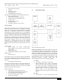
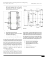
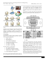
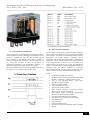
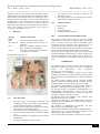
International Journal For Technological Research In Engineering Vol. 1, Issue. 1, Sep – 2013 ISSN (Online): 2347 - 4718 REMOTE DATA ACQUISITION USING WIRELESS SCADA SYSTEMS Md Mazharuddin Harsoori1, Mursal Ayub Hamdani2, Prashant Kadi3 1, 2, 3 Department of Instrumentation Tech, Dayananda Sagar College, VTU,Belgaum, Bangalore,India 1 [email protected] 2 [email protected] 3 [email protected] Abstract: The present trend of tariff collection suffers from inefficient system of billing and collection in the way of waiting of valuable manpower. So our aim is to overcome these problems with the introduction of automatic power reading and sending those readings to electricity board for automatic E billing through the SMS using GSM phone. It will also send if power theft is going on in any building with the GSM MODEM sending an SMS to the electricity board automatically .This is a new approach to tariff collection. The development of a GSM automatic power meter reading system [GAPMRS] is presented in this paper. The GAPMR system consists of GSM digital power meters installed in every consumer units and an electricity ebilling system at energy provider side. A GSM digital power meter is a single phase IEC61036 standard compliance digital kwh power meter with embedded GSM modem which utilize the GSM network to send its power usage reading using short messaging system [SMS] back to the energy provider wirelessly. At the power provider side an e billing system is used to manage all received SMS meter reading, compute the billing cost, update the database and to publish billing notification to its respective consumer through SMS, email, web portal, and printed postage mailing. A working prototype of the GAPMR system was built to demonstrate the effectiveness and efficiency of automatic meter reading, billing and notification through the use of GSM network. Keywords: SCADA, operational block-diagram, microcontroller, software tools, results. I. INTRODUCTION The purpose of this material is to remote monitoring and control of the domestic energy meter. This system enables the electricity department to read the meter readings regularly without the person visiting each house. This can be achieved by the use of microcontroller unit that continuously monitors and records the energy meter readings in its permanent (nonvolatile) memory location. This system also makes use of a GSM modem for remote monitoring and control of energy meter. The microcontroller based system continuously records the readings and the live meter reading can be sent to the electricity department on request. This system also can be used to disconnect the power supply to the house in case of non-payment of electricity bills .A dedicated GSM modem with SIM card is required for each energy meter. This material investigates on creating an extremely low cost device which can be adapted to many different SCADA applications via some very basic programming and plugging in the relevant peripherals. Much of the price in some expensive SCADA applications is a result of using specialized communication infrastructure. The application of infrastructure in the proposed scheme makes the cost to come down. Additionally the generic nature of the device will be assured. SCADA refers to a system that collects data from various sensors at a factory, plant or in other remote locations and them sends this data to a central computer which then manages and controls the data. SCADA is a term that is used broadly to portray control and management solutions in a wide range of industries. Some of the industries where SCADA is used are water management systems, electric power, traffic signals, mass transit systems, environmental control systems and manufacturing systems. SCADA system consist of the following subsystems: A human machine interface [HMI] is the apparatus which presents process data to a human operator and through which the human operator monitors and controls the process. A supervisory system, gathering data on the process and sending commands to the process Remote Terminal Units (RTUs) connecting to sensors in the process, converting sensor signals to digital data and sending digital data to the supervisory system Communication infrastructure connecting the supervisory system to the remote terminal unit. Functions A SCADA system is used to monitor or control a chemical, physical and transport process [1]. Integrated with power system management application functions, it provides an integrated distribution management system to improve the reliability of power supplies, manage the load effectively, reduce restoration times and increases the utilization efficiency of the network equipment. The functions of SCADA are: Real time data exchange 37 International Journal For Technological Research In Engineering Vol. 1, Issue. 1, Sep – 2013 Real time data processing Tagging Supervisory control Switching orders Load shedding and restoration The distribution management system [DMS] functions are: Operational monitoring Fault isolation and system restoration Variable reactive power(VAR) control Voltage control Distribution power flow Load forecasting Calculation of quality service indices II. ISSN (Online): 2347 - 4718 BLOCK DIAGRAM System concepts The term SCADA usually refers to centralized systems which monitor and control entire sites or complexes of systems spread out over large areas (anything between an industrial plant and a country).Most control actions are performed automatically by remote terminal units or by programmable logic controllers. Host control functions are usually restricted to basic overriding or supervisory level capability [2]. For example, a PLC may control the flow of cooling water through part of an industrial process but the SCADA system may allow operators to change the set points for the flow and enable alarm conditions such as loss of flow and high temperature, to be displayed and recorded. The feedback control loop passes through the RTU or PLC while the SCADA system monitors [3] the overall performance of the loop Hardware used GSM modem for remote communication Electromagnetic relay and relay driver for power supply control Digital energy meter LCD display to display the meter readings Software used Keil u-vision 3.0 keil software is used to provide the software development tools for 8051 based microcontrollers. With the keil tools, we can generate embedded applications for virtually every 8051 derivative. Proload Programmer Software Proload is a software working as user friendly interface for programmer boards from sunrom technologies. Proload gets its name from “Program Loader” term as it takes in compiled HEX file and loads it to the hardware. Features of Proload : Supports major Atmel 89 series devices Auto identify connected hardware and devices Error checking and verification in-built 20 and 40 pin ZIF socket on-board Works on 57600 speed Fig. 1. Operational block diagram of remote data acquisition using wireless SCADA system Theory of operation: In this material, 89S52 microcontroller is interfaced with SIM 300T GSM modem to decode the received message and do the required action. The protocol used for the communication between the two is AT command The microcontroller pulls the SMS received by phone, decode it, recognizes the mobile number and then switches on the relays attached to its port to control the appliances. After successful operation, controller sends back the acknowledgement to the user’s mobile through SMS. A) Sensor A thermistor is used here as a heat sensor When temperature in the vicinity of thermistor increases, the value of the resistance is decreased in case of fire. The voltage is compared with other input and produce voltage at relay and the relay gets activated. When the relay is activated it sends negative voltage to the microcontroller. The microcontroller sends the SMS to the concerned people B) ADC A/D converters convert an analog voltage to the 38 International Journal For Technological Research In Engineering Vol. 1, Issue. 1, Sep – 2013 digital output that best represents an input. Analog converters are also specified as 8, 10, 12 or 16 bit. This section discusses only the successive approximation type, which uses a comparator, an SAR, output latches and D/A converter. ISSN (Online): 2347 - 4718 to the circuit. Fig. 3. Circuit diagram of full wave regulated power supply using IC’s Fig. 2. Pin diagram of ADC0809 Features of ADC0809: Easy interface to all microprocessor Operates ratio metrically or with 5V dc or analog span adjusted voltage reference No zero or full scale adjust required 8-channel multiplexer with address logic 0V to 5V input range with single 5V power supply Outputs meet TTL voltage level specifications The output of the various parameters is fed to A/D converter .The channel selection depends upon the address selection sent by the microcontroller. The channel selection depends upon the address selection sent by the micro controller. For ADC to start converting the data after selecting the channel by sending the address inputs, the start conversion signal is to be sent by microcontroller. Then ADC starts converting the analog signal voltage into corresponding digital data. After conversion, the ADC generates EOC (End of Conversion).This indicates to microcontroller that the conversion is completed and takes the digital data corresponding to analog input. D) GSM modem (900/1800 MHz) A GSM modem is a wireless modem that works with a GSM wireless network. A wireless modem behaves like a dial-up modem .The main difference between them is that a dial-up modem sends and receives data through a fixed telephone line while a wireless modem sends and receives data through radio waves. A GSM modem can be an external device or a PC card/PCMCIA card. Typically an external GSM modem is connected to a computer through a serial cable or a USB cable. Like a GSM mobile phone, a GSM modem requires a SIM card from a wireless carrier in order to operate. A SIM card contains the following information: Subscriber telephone number(MSISDN) International subscriber number(IMSI, International Mobile Subscriber Identity) State of the SIM card Service code Authentication key PIN(Personal Identification Code) PUK(Personal Unlock Code) C) Regulated Power Supply The circuit needs two different voltages, +5V and +12V to work. These dual voltages are supplied by this specially designed power supply. The main object of this power supply is to deliver the required amount of stabilized and pure power 39 International Journal For Technological Research In Engineering Vol. 1, Issue. 1, Sep – 2013 ISSN (Online): 2347 - 4718 9 pins. Since RS232 is not compatible with microcontrollers we need a voltage converter to convert the RS232’s signals to TTL voltage levels. These are acceptable to the microcontroller’s TxD and RxD pins. The MAX 232 converts the RS232 voltage levels to TTL voltage levels and vice versa. The chip uses +5v power source which is the same as the power source for the microcontroller. It provides 2-channel RS232C [7] port and requires external 10uF capacitors. Fig. 4. An overview of GSM based automatic meter reading system Computers use AT commands to control modems. Both GSM modems and dial up modems support a common set of standard AT commands. In addition to the standard AT commands, GSM modems support an extended set of AT commands. These extended AT commands are defined in the GSM standards. AT Commands: AT Commands are used to control a modem. AT means Attention. Every command line starts with “AT”. These are of two types: Basic and Extended. ATEO – Echo off ATE1- Echo on ATD –Call a dial no. ATDL- Redial last telephone no. ATA- Answer an incoming call ATH-Disconnect existing connection AT+CMGS-To send SMS AT+CMGR – To read SMS AT+CMGD – To delete SMS LED Status Indicator in GSM Modem: OFF - Modem Switched off On - Modem is connecting the network Flashing Slowly - Modem is in idle mode Flashing rapidly - Modem is in transmission E) Serial communication using RS232 RS 232 stands for Recommend Standard number .Most new PC’s are equipped with male D type connectors having only Fig. 5. RS232 DB9 along with pin details. F) Relay A relay is an electromechanical switch. More importantly, relays are used in virtually every type of electronic device to switch voltages and electronic signals. Relays are very powerful devices in the fact they can be used in virtually every industry: automobile, telephone systems, medical devices, and car stereo systems. Basically a relay is an electrical switch that uses an electromagnet to move the switch from the off to on position instead of a person moving the switch. It takes a relatively small amount of power to turn on a relay but the relay can control something that draws much more power. Example: A relay is used to control the air conditioner in home. The AC unit probably runs off of 220VAC at around 30A. That's 6600 Watts! The coil that controls the relay may only need a few watts to pull the contacts together. 40 International Journal For Technological Research In Engineering Vol. 1, Issue. 1, Sep – 2013 ISSN (Online): 2347 - 4718 Fig 8.Pin details of 44780 based LCD Fig. 6. Practical Relay driver used on PCB H) Microcontroller(AT89S52) G) LCD (Liquid Crystal Display ) LCDs can add a lot to any application in terms of providing a useful interface for the user, debugging an application or just giving it a “professional” look. The most common type of LCD controller is the Hitachi 44780 which provides a relatively simple interface between a processor and an LCD [6]. Using this interface is often not attempted by inexperienced designers and programmers because it is difficult to find good documentation on the interface. The most common connector used for the 44780 based LCDs is 14 pins in a row with pin centres 0.100’’ apart. Fig .7. LCD Data Write Waveform The AT89S52 is a low-power, high-performance CMOS 8bit microcontroller with 8K bytes of in-system programmable Flash memory. The device is manufactured using Atmel’s high-density non-volatile memory technology and is compatible with the Industry standard 80C51 instruction set and pin out. The on-chip Flash allows the program memory to be reprogrammed in-system or by a conventional nonvolatile memory programmer [4] [5] [8]. By combining a versatile 8-bit CPU with in-system programmable Flash on a monolithic chip, the Atmel’s AT89S52 is a powerful microcontroller which provides a highly-flexible and costeffective solution to many embedded control application. Features: Compatible with MCS-51 Products 8K Bytes of In-System Programmable (ISP) Flash Memory – Endurance: 1000write/Erase Cycles 4.0V to 5.5V Operating Range , Fully Static Operation: 0 Hz to 33 MHz 256 x 8-bit Internal RAM 32 Programmable I/O Lines Three 16-bit Timer/Counters Eight Interrupt Sources ,Three-level Program Memory Lock ASCET.ECE.dept16 Full Duplex UART (Universal Asynchronous Receiver Transmitter) Serial Channel Low-power Idle and Power-down Modes Interrupt Recovery from Power-down Mode Dual Data Pointer Power-off Flag Fast Programming Time Flexible In System Programming (Byte and Page Mode) 41 International Journal For Technological Research In Engineering Vol. 1, Issue. 1, Sep – 2013 ISSN (Online): 2347 - 4718 addressing, so the upper 128 bytes of data RAM are available as stack space. III. CIRCUIT DIAGRAM Fig .9. Pin Diagram of AT89S52 Memory Organization: AT89S52 have a separate address space for Program and Data Memory [9] [10] Up to 64K bytes each of external Program and Data Memory can be addressed [8]. Program Memory: If the EA pin is connected to GND, all program fetches are directed to external memory. On the AT89S52, if EA is connected to VCC, program fetches to addresses 0000H through 1FFFH are directed to internal memory and fetches to addresses 2000H through FFFFH are to external memory. Data Memory: The AT89S52 implements 256 bytes of onchip RAM. The upper 128 bytes occupy a parallel address space to the Special Function Registers. This means that the upper 128 bytes have the same addresses as the SFR space but are physically separate from SFR space. When an instruction accesses an internal location above address 7FH, the address mode used in the instruction specifies whether the CPU accesses the upper 128 bytes of RAM or the SFR space. Instructions which use direct addressing access the SFR space. For example, the following direct addressing instruction accesses the SFR at location 0A0H (which is P2). MOV 0A0H, #data Instructions that use indirect addressing access the upper 128 bytes of RAM. For example, the following indirect addressing instruction, where R0 contains 0A0H, accesses the data byte at address 0A0H, rather than P2 (whose address is 0A0H). MOV @R0, #data Note that stack operations are examples of indirect Fig .10. Circuit flow of the entire process IV. OPERATION At each blink of LED of meter reading, a signal is passed to the microcontroller to count the pulses of meter reading. Then microcontroller updates the reading and displays it over LCD and also saves it to the memory. The LCD and memory are connected to port 0 of microcontroller. For transferring the data a GSM modem is used, which sends SMS to the particular mobile number defined. The MAX232 is used to interface GSM modem,. The home unit consists of a LCD display unit and a GSM modem connected to microcontroller with MAX232 using serial communication port RS232.The major component of the home interface is the microcontroller ATMEL AT89S52 which has a 256 bytes of RAM memory. The unique id which is assigned to each home unit is stored in this memory. The microcontroller checks the message which reaches from the central EB office, if the destination id matches its id then the work is done else the message is discarded. The home unit is connected to the EB office via GSM which transmit data to the EB office. The microcontroller automatically sends the number of units consumed by the customer to the EB office after a particular 42 International Journal For Technological Research In Engineering Vol. 1, Issue. 1, Sep – 2013 duration of time say two months. This message is used to update the back end database and the computation is done. The EB office sends the bill back to the home unit which is displayed on the LCD display. The user is also intimated by an SMS which is sent to his/her mobile phone. Power theft identification is done by means of an alarm, which is connected to the 39th pin of IC AT89S52. Once the alarm is set on, the resetting of the controller can be done by connecting a push button to pin 9. V. 7. 8. VII. VIII. Message Code AP6 AP1,AP2,AP3 RD *Amt# The number of cards released by electricity can predetermine load The supply authorities can maintain good relation and gain good will from consumer APPLICATIONS 1. 2. 3. 4. RESULTS ISSN (Online): 2347 - 4718 Home purpose Industrial School and college Commercial shops and office. CONCLUSION AND FUTURE SCOPE Operation Performed Switches ON/OFF the main supply Switches ON/OFF respective relays for appliances Sends the message containing current meter reading to the EB number This code is used to send the total amount to be paid by the customer Working demo of the process: The present situation smart house is all using manual communication. To reduce the manual efforts and human errors, we need to have some kind of automated system monitoring all the parameters and functioning of the connections between the pilot and the airport personnel. We are trying to implement prototype model of a smart house system within the limited available source and economy The system can be subjected to further development using advanced techniques. It may become a success if this process can be implemented in the modern airports. However a machine is equivalent to 1000 humans input. The same works here. REFERENCES: Fig .11. Depiction of the entire process on a board VI. ADVANTAGES 1. 2. 3. 4. 5. 6. The man power is decreased considerably and recording of energy meter reading and preparation of bills for other consumers is simplified Accurate meter reading and billing and no problems due to faulty and non-reading meters The customer is free from maintaining past records No meter reading problem due to the door locked cases The main advantage is avoiding the problem of tariff collection[11] Detection of tampering and power theft [1] Sungmo Jung,Jae-gu Song, Seoksoo Kim,” Design on SCADA Test-bed and Security Device”, International Journal of Multimedia and Ubiquitous Engg,Vol.3,No.4,October,2008 [2] Alexander, R.L., Intelligent electronic device (IED) technology SCADA and 3-phase metering, Rural Electric Power Conference, 2002.2002 IEEE, 5-7 May 2002 Pages: C6-C6-3. [3] Sandip C.Patel, Pritimoy Sanyal “Securing SCADA System “Information Management & Computer Security Journal Volume: 16 .Issue:4 Page: 398-414 year: 2008 [4] Motorola Semiconductor Technical Data, Technical Summary: 16-Bit Microcontrollers, Motorola Inc, .1997 [5]. Ricardo B.Uribe,” Experiment #10:Introduction to a Programmable Microcontroller,” Class notes for ECE 249,Department of Electrical and Computer Engineering, University of Illinois, Urbana, Fall 1999. [6] BPI-216 Serial LCD Modules, User’s Manual, Scott Edwards Electronics Inc, Jul.2000. [7] Serial Port (RS-232),”9 Pin D-Shell (DB-9) Connector PinLayout,”October2000,http://servicepac.de.ibm.com/eprm .html/eprm/254.htm. [8] Textbook of Muhammed Ali Mazidi, the 8051 Microcontroller and embedded systems [9].Textbook of Kenneth J Ayala,The 8051 Microcontroller [10].Textbook of I Scott Mackenzie, Raphael C.-W. Phan,The 8051 Microcontroller,4th Edition [11]. Principles and Applications of GSM by Vijay K Garg 43