1
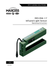
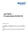
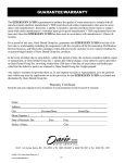
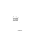
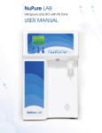
USER MANUAL
Advantage™ Nitrogen Generator Models:
ANS20F ANS34F
ANS America Corporation
1112 North Collier Boulevard
Marco Island, FL 34145
Tel: 239-394-6099 Fax: 239-394-5388
www.ans-america.com
Copyright© 2007 ANS America Corporation
-1-
Table of Contents
1. INTRODUCTION
3
1.1 GENERAL ............................................................................................................................................... 3
1.2 PICTOGRAMS IN THIS MANUAL .............................................................................................................. 3
1.3 IDENTIFICATION AND SERVICE ............................................................................................................... 4
1.4 USE IN ACCORDANCE WITH PURPOSE ..................................................................................................... 4
1.5 USER INSTRUCTIONS .............................................................................................................................. 4
1.6 LIABILITY .............................................................................................................................................. 4
2 HEALTH, SAFETY AND ENVIRONMENTAL ASPECTS
5
2.1 GENERAL ............................................................................................................................................... 5
2.2 COMPRESSED AIR .................................................................................................................................. 5
2.3 NITROGEN AND OXYGEN ....................................................................................................................... 5
2.4 SAFETY PRECAUTIONS ........................................................................................................................... 6
2.5 ENVIRONMENTAL ASPECTS .................................................................................................................... 6
3 DESCRIPTION OF THE APPLIANCE
7
3.1 GENERAL ............................................................................................................................................... 7
3.2 SEPARATION PRINCIPLE ......................................................................................................................... 7
3.3 PROCESS PARAMETERS .......................................................................................................................... 8
3.4 PROCESS SCHEMES ................................................................................................................................ 9
4 TECHNICAL SPECIFICATIONS
10
4.1 GENERAL ............................................................................................................................................. 10
4.2 REPLACEMENT PARTS ......................................................................................................................... 10
5. INSTALLATION
11
5.1 TRANSPORT ......................................................................................................................................... 11
5.2 DEFINE LOCATION ............................................................................................................................... 11
5.3 UNPACK AND CHECK EQUIPMENT (REFER TO SECTION 5.3.1) ............................................................. 11
5.3.1 PARTS CHECKLIST ............................................................................................................................ 11
5.3.2 ITEMS REQUIRED BY CUSTOMER FOR PROPER INSTALLATION: .......................................................... 12
5.4 CONNECT PREFILTRATION PACKAGE TO ADVANTAGE NITROGEN SYSTEM ......................................... 12
5.5 CONNECTION TO COMPRESSED AIR FEED AND NITROGEN CONSUMER .................................................. 13
5.6 COMMISSIONING OF AN ADVANTAGE NITROGEN SYSTEM .................................................................. 14
5.7 ADJUSTING THE PURITY ....................................................................................................................... 14
5.8 ADJUSTING THE PNEUMATIC PRESSURE SWITCH (OPTIONAL) .............................................................. 14
6 OPERATION
16
6.1 START-UP OF ADVANTAGE NITROGEN SYSTEM ................................................................................... 16
6.2 STOP OPERATION OF ADVANTAGE NITROGEN SYSTEM........................................................................ 16
6.3 TROUBLESHOOTING ............................................................................................................................ 16
7 MAINTENANCE
17
7.1 MAINTENANCE SCHEME ...................................................................................................................... 17
7.2 REPLACE FILTER ELEMENT .................................................................................................................. 17
7.3 CLEAN AUTOMATIC DRAIN .................................................................................................................. 18
7.4 REPLACE CARBON ............................................................................................................................... 18
-2-
1. Introduction
1.1 General
The Advantage Nitrogen System is a product of ANS America Corporation. This manual forms
an integral part of the product. The manual describes the daily operation, maintenance required
and troubleshooting techniques, if necessary.
Content
Read the manual carefully before you start with the Advantage Nitrogen System. Familiarize
yourself with the content.
Condition of change
Only execute changes to the Advantage Nitrogen System after explicit prior written permission
by ANS America. Non-conformance to this rule, as well as any consequential damage, loss and
costs are the responsibility of the owner and the user.
Information
All information in this manual, including additional drawings and technical descriptions, remains
the property of ANS America Corporation and may not be used (other than for the use of this
product), copied, multiplied or published to or for a third party without explicit prior written
permission by ANS America Corporation.
1.2 Pictograms in this manual
In this manual the following pictograms are used:
Warning
A warning shows a hazard that can cause death or serious injury. Follow
the instructions.
Caution
A caution shows a danger that can cause damage to the equipment.
Follow the instructions.
Warning
Risk of death due to suffocation.
Risk of fire
Oxygen-enriched air leads to an increased risk of fire in the event of
contact with inflammable products.
High pressure risk
Follow the instructions with respect to compressed gasses.
Instructions with respect to the environment.
-3-
1.3 Identification and service
The identification plate is located on
the left side of the Advantage Nitrogen System and
shows its characteristics.
For service and technical
assistance, please contact:
ANS America Corporation
1112 North Collier Boulevard
Marco Island, FL 34145
Tel: 239-394-6099 Fax: 239-394-5388
www.ans-america.com
1.4 Use in accordance with purpose
The Advantage Nitrogen System nitrogen generator is intended to make nitrogen out of normal
ambient air. The system is based on gas separation membrane technology. Each different or
further use will not be in conformity with this purpose. ANS America will not accept any liability for
improper use. The Advantage Nitrogen System nitrogen generator is in compliance with the
prevailing directives and standards. Only use this Advantage Nitrogen System in a technically
perfect condition, in conformity with the purpose as described above.
1.5 User instructions
Only properly trained personnel are allowed to work on the Advantage Nitrogen System nitrogen
generator. The user must be aware of hazards related to operating the Advantage Nitrogen
System and processes connected to it. The user is responsible for the safety of personnel
nearby. All personnel working on the Advantage Nitrogen System must have free access to the
applicable manuals.
1.6 Liability
ANS America Corporation will not accept any liability if:
o The instructions in this manual are ignored.
o Replacement parts are used which are not approved by the manufacturer.
o The system is operated incorrectly.
o The system is fed with gasses other than air.
o The system is modified without notification and authorization of the manufacturer.
o Maintenance and repair are not carried out according to the instructions.
-4-
2 Health, safety and environmental aspects
2.1 General
Correct use of the Advantage Nitrogen System nitrogen generator is important for your
personal safety and for trouble-free functioning of the Advantage Nitrogen System. Incorrect
use can cause damage to the Advantage Nitrogen System or can lead to incorrect gas supply
to the customer’s process.
Warning
o Read this manual before you start the installation and begin operation of
the Advantage Nitrogen System. Prevent accidents and damage to the
Advantage Nitrogen System.
o Contact your supplier if you detect a problem that you cannot solve with
this manual.
o Use the Advantage Nitrogen System in accordance with its purpose. Refer
to section 1.4.
o Only service-engineers that are qualified to work on pneumatic equipment
are allowed to do the installation, maintenance and repairs. Refer to section
1.5.
o Do not tamper or experiment with the equipment. Do not exceed the
technical specifications for the Advantage Nitrogen System. Refer to
section 4.1.
2.2 Compressed air
Warning
o Ensure that the feed air pressure can not exceed 190 psig.
o Ensure that the equipment and the attendant piping is connected correctly
for the pressures required.
o Depressurise the Advantage Nitrogen System and the connected systems
before you disconnect parts of the system. The sudden escape of
compressed air can cause serious injury or damage. Refer to section 6.2.
2.3 Nitrogen and oxygen
The Advantage Nitrogen System generates nitrogen as a product. Oxygen enriched air is
released as waste.
Warning
o
o
o
Nitrogen can cause suffocation!
Oxygen-enriched air leads to increased risk of fire in the event of contact
with flammable products. Make sure that there is adequate ventilation at
all times!
Do not install the Advantage Nitrogen System in an area where explosive
substances may be present.
-5-
2.4 Safety precautions
Warning
o
o
o
o
o
o
o
Ensure there is sufficient ventilation.
Only feed the Advantage Nitrogen System with air.
Keep the air feed to the Advantage Nitrogen System clean and free of vapors of
organic solvents and other contaminants. Do not place the Advantage Nitrogen
System in a room where organic solvent vapors may be present.
Keep the ambient temperature between 40 and 110 °F. Do not connect hot
compressed air directly from a compressor to the inlet of the Advantage Nitrogen
System.
Install the peripheral equipment and piping according to all applicable local
regulations. ANS America Corporation is not responsible for customer installed
piping.
Regular maintenance should be performed on the Advantage Nitrogen System to
ensure proper and safe operation. Refer to chapter 7.
Ensure that instructions concerning health and safety are compliant with local
regulations.
2.5 Environmental aspects
The use and maintenance of the Advantage Nitrogen System do not include environmental
dangers. Most parts are made of metal and can be disposed of in a manner consistent with local
regulations. The packaging of the Advantage Nitrogen System is 100% recyclable.
o
Make sure that instructions concerning health, safety and environment
are compliant with all local regulations.
-6-
3 Description of the appliance
3.1 General
The Advantage Nitrogen System separates compressed air into nitrogen and an oxygen enriched
air stream. The separation system is based on membrane technology. The compressed air
comes from a central system or from a dedicated compressor.
The nitrogen produced is usually stored in a nitrogen storage vessel. The Advantage Nitrogen
System then switches on and off, depending on the nitrogen demand.
3.2 Separation principle
Separation layer
Support layer
B
Pressurised air
Nitrogen
C
A
H2 O, H2
O2
N2
S
F
Fig. 3-1: Separation principle
A
B
C
Pressurized air inlet
Hollow fibre membrane
Nitrogen outlet
F
S
Fast
Slow
Ambient air contains nitrogen (78.1%), oxygen (20.9%), argon (1%), carbon dioxide, water vapor
and traces of other inert gasses. Pressurised air (A) is fed through the hollow fibre membrane (B).
The various air components diffuse through the wall of the membrane.
The diffusion rate differs for the various gasses:
• Oxygen and water vapor have a high diffusion rate and permeate rapidly through the
membrane wall.
• Nitrogen has a low diffusion rate and permeates slowly through the membrane wall.
At the exit of the membrane (C), pressurized nitrogen is released.
-7-
3.3 Process parameters
The nitrogen production depends on these parameters:
Flow rate
The lower the flow rate of compressed air through the hollow fibre membrane, the more
oxygen can permeate through the membrane wall. As a result, the nitrogen produced at
the outlet will have a higher purity. Nitrogen purity can be adjusted with the flow control
valve.
Temperature
The Advantage Nitrogen System operates optimally at a temperature between 68-80°F. If
the temperature increases, the pressurized air consumption will also increase. Do not
place the system in a room where the temperature may rise unnecessarily high.
Allow enough piping between the compressor exit and the Advantage Nitrogen System
inlet so that the hot compressed gas has time to cool within the specifications listed in
this manual.
Membrane pressure
A higher membrane pressure will increase the capacity (i.e. nitrogen output) of the
Advantage Nitrogen System. Pressure also enables operation of the pneumatic shut-off
switch.
External pressure
There must be atmospheric pressure at the vent or permeate outlet. The capacity and the
purity of the nitrogen gas decreases strongly if the vent or permeate pressure exceeds
the atmospheric pressure.
-8-
3.4 Process Schemes
3.4.1 Models ANS-20F, ANS-34F
Permeate
Outlet
PRV
PSH
Inlet
F-01
F-02
DX
BX
F-02
C
Product
BX
V-2
V-1
FCV
V-3
M-1, M-2 ...
PI-1
F-01, F-02
Coalescing filter
V-1
Ball valve
M-1, M-2, ...
Gas separation membrane
FCV
Flow control valve
V-2
Valve
C
Activated carbon bed
PI-1
Pressure gauge
PSH
Pressure switch
ST
Storage tank
PRV
Pressure relief valve
V-3
Non-return valve
ST
-9-
4 Technical specifications
4.1 General
Delivery pressure
Maximum delivery pressure
Compressed air
Maximum feed pressure
Minimum feed pressure
Compressed air temperature
range
Residual oil content
Atmospheric dew point
Air Consumption
ANS-20F
ANS-34F
Inlet pressure minus 15 psi
145 psi(g) / 13 bar(g)
145 psig
50 to 104 °F (10°C to 40°C)
< 0.01 mg/m3
-50 °F(-45.6°C)
45.5 SCFM
88.4 SCFM
Ambient conditions
Temperature
Noise level
Dimensions and connections
Dimensions
Net weight
Connections
inlet
Outlet (tank)
Storage Tank Dimensions
Storage Tank Weight
Output
Capacity at nominal conditions(2)
Purity at specified capacity
[% by volume]
33 to 110 °F
Less than 45 dB(A)
33”H x 22”W x 6”D
69”H x 24”W x 20”D
88 lbs.
210 lbs.
½” NPT
3/4” NPT
½” NPT
½” NPT
40”H x 18”D (30 gal. tank)
125 lbs. (30 gal. Tank)
20 SCFM
34 SCFM
95
1 Nominal conditions are 145 psig supply air pressure, 68°F ambient air temperature.
Table 4-1: General data
4.2 Replacement Parts
Part
• ANS-20F Maintenance Kit
P/N
MK-ANS-
•
MK-TS24F
ANS-34F Maintenance Kit
- 10 -
5. Installation
Follow the sections in this chapter to install the Advantage Nitrogen System.
5.1 Transport
Warning
o
o
Put the Advantage Nitrogen System in the original box to transport it over longer
distances.
For qualifications of installation personnel, refer to section 2.1.
5.2 Define location
1. Install the Advantage Nitrogen System in a fixed location. The location must meet following
requirements:
• Indoors.
• Dry.
• Vibration free.
• No continuous, direct sunlight.
• Away from heat sources.
• Properly ventilated room. Refer to section 2.4.
• Easy accessibility for operation and service.
Perform the complete installation procedure again if you move the Advantage Nitrogen System to
a new location.
5.3 Unpack and check equipment (refer to section 5.3.1)
1. Open the packaging.
2. Ensure that all components are delivered.
3. Ensure that the available compressed air meets specification:
• Oil content of the compressed air is below 0.01mg/m3.
• If the Advantage Nitrogen System is connected to a house air system: ensure that the
compressed air pressure and quality is always as prescribed. The capacity must be
sufficient.
• If the Advantage Nitrogen System is connected to a stand-alone compressor: ensure that
the compressor works properly. Refer to the instructions of the compressor manufacturer.
Ensure that the after cooler and the water separator of the compressor work correctly.
• If installed, ensure that the pressurised air dryer is of proper size and that it is in working
order.
5.3.1 Parts Checklist
Items included in the package:
1. Advantage Nitrogen System Nitrogen Generator.
2. Installation and operation manual.
3. [ANS-34F] Prefiltration package consisting of two coalescing filters and a carbon adsorption
tower. Hose is included for connecting systems together.
4. [Optional] Nitrogen Storage Tank. Tank has pressure relief valve located on top – DO NOT
REMOVE or ADJUST. A green hose is included to connect outlet of the generator to the
storage tank.
5. [Optional] Point of sale materials.
- 11 -
5.3.2 Items required by customer for proper installation:
1. Suitable way to attach process air from plant to the inlet of the prefiltration package
[ANS-34F] or to the Advantage Nitrogen System generator directly [ANS-20F]. The
inlet connection for the ANS-20F is ½” FNPT (see section 4.1). The ANS-34F inlet
connection is ¾” FNPT.
2. Suitable connection from nitrogen storage tank to customer’s tire filling hoses or
manifold. The tank exit connection is ½” FNPT. For multiple nitrogen hose drops,
considering installing a pipe Tee or some sort of manifold if one does not already
exist.
3. Use PTFE pipe seal tape or other suitable thread sealant for the NPT thread
connections. Note: the hose connections for the included ½” green hose seal with
special flare fittings – do not use any sort of thread sealant on these connections. It
is sufficient to ensure that they are tight for a leak-free connection.
4. It is recommended to install a drip leg on the inlet side of the system to catch loose
particles in the piping system. Consult a local plumber for assistance if needed.
5. Mounting dimensions or system footprint:
Figure 5.1: Mounting Dimensions ANS-20F, ANS-34F (Top View)
5.4 Connect Prefiltration Package to Advantage Nitrogen System
The Carbon Absorber for the Advantage Nitrogen System includes two stages of
coalescing prefiltration and an activated carbon adsorption bed. Use the supplied rubber
hose to connect the outlet of the carbon bed to the inlet of the Advantage Nitrogen System
(see Figure 5.3). The prefiltration package for the ANS-20F is located inside the cabinet;
for the ANS-34F it is a stand-alone tower. See Figure 5.3.
- 12 -
5.5 Connection to compressed air feed and nitrogen consumer
Warning
o
Make sure that the inlet and outlet hose and pipe are free of dust, particles, metal parts
and curls, liquids and grease before you connect the Advantage Nitrogen System.
1. Connect the product outlet to the application or storage vessel.
2. [ANS-20F] Connect the compressed air supply to the compressed air inlet (see Figure 5.2).
3. [ANS-34F] Connect the compressed air source to the inlet of the first filter (see Figure 5.3).
Figure 5.2: Installation Schematic ANS-20F
Figure 5.3: Installation Schematic ANS-34F
(ANS-20F: Carbon tower/prefiltration interval)
- 13 -
5.6 Commissioning of An Advantage Nitrogen System
1.
2.
3.
4.
5.
Ensure that the connections are correct and tightened.
Open the compressed air supply slowly.
Ensure that the compressed air pressure is as high as expected.
Ensure that the installation has no leaks which may have arisen due to transport.
Ensure that the system starts to consume pressurised air when the nitrogen outlet is opened
and that air consumption stops when the nitrogen outlet is blocked again.
6. The system is ready for use now.
5.7 Adjusting the purity
The purity is factory pre-set at 97%, which means that there is 5% residual oxygen. The
purity has been set by adjusting the flow control valve. Normally the setting is stable and
does not need to be checked.
If it becomes necessary to adjust the purity, this can be done by adjusting the flow control
valve until the purity, as measured with an oxygen analyzer taking a sample from the
outlet, has the desired purity.
5.8 Adjusting the pneumatic pressure switch (Optional)
The pressure switch (PSH or “Pilot Valve”) is factory pre-set to 130 psig such that the Advantage
Nitrogen System switches off when there is no consumption and that it switches back on when
there is consumption of nitrogen. Note that the pressure switch will always leak a small amount
of air.
Important
Adjusting the pressure switch set point is required for successful
installation of the Advantage Nitrogen System system, if operated at
Inlet condition lower than the factory set point as described above.
o
o
If the switch set point is set too high, the supply will never turn off, and
the compressor will run constantly.
If it is set too low, the Advantage Nitrogen System will not take advantage
of all of the pressure available from your compressed air supply. The
system will operate reliably, just not at maximum capacity and pressure.
Upon commissioning the system, allow the system to run so that the storage tank fills.
After a period of time, the nitrogen storage pressure should stop rising, the system turns
off, and there is no more demand for air from your compressor.
If the compressor/system does not shut off, the pressure switch is set too high and the
set point on the pressure switch needs to be reduced so the system turns off.
If the compressor shuts off as expected, there may be an opportunity to increase the
performance of your system. If your compressor is capable of high PSI/CFM you may
want to try to increase the set point on the pressure switch set. This will increase the
pressure of nitrogen in the storage tank that is available for filling tires.
- 14 -
Warning
Never set the pressure switch so that the technical specifications of the
Advantage Nitrogen System are exceeded; this can cause serious injury and/or
damage (see Chapter 4.1 for specifications). The maximum pressure setpoint in
the tank is 145 psig. DO NOT EXCEED THIS PRESSURE.
The pressure switch is as shown:
To Adjust:
1. Loosen lock-nut 1.
2. The set point for the pressure switch can be increased by turning the pressure rod at
the finger grip clockwise and decreased by turning it counter-clockwise. Be careful
with turning the pressure rod counter-clockwise. If you loosen too much the pressure
rod could back all the way out. When decreasing the pressure set point, turn the
pressure rod counter clock-wise until the system turns off, then turn counter clockwise another ¼ of a turn to ensure the compressor will shut off.
3. The differential screw does not need adjustment. Erroneous setting causes the
pressure switch to pop repeatedly. Should its setting be changed erroneously, reset it
as follows.
A. Loosen lock-nut 2.
B. Turn the differential screw clockwise until it can go no further and turn it counterclockwise ¼ turn.
4. Retighten all locknuts, being careful not to twist pressure rod.
Once the set point is adjusted, it is important to test the system as follows.
Allow some nitrogen to vent from the storage vessel (e.g. open a valve slowly) until the
compressor/system turns back on. Close the vent source, and see if system turns off. If
so, the set point is adjusted correctly, retighten lock nut on adjustment screw. If the
compressor/system does not shut off, you will need to lower the set point slightly until the
compressor/system shuts off.
It is recommended to repeat this test 3 times to ensure that the set point on the pressure
switch is set correctly.
- 15 -
6 Operation
6.1 Start-up of Advantage Nitrogen System
1. Open the compressed air supply.
2. The system will start to produce nitrogen as soon as the nitrogen outlet is opened. The
specified purity will be available instantaneously.
6.2 Stop operation of Advantage Nitrogen System
1. Shut off the pressurised air supply before you perform maintenance.
2. Depressurise the system by venting the nitrogen outlet.
3. Ensure that the system is fully depressurised by checking the pressure gauge.
TIP: should the filters not be fully depressurized it is possible to depressurize them manually by slowly
unscrewing the bleed screw on the bottom of the filter bowl on one of the filters. Prior to reinstalling
the bleed screw after venting, ensure the o-ring is seated properly. It may be necessary to vent the
filters all the way down to atmospheric pressure so that the o-ring will seat.
6.3 Troubleshooting
Error
Delivery of
nitrogen too
low or absent
Possible cause
Compressed air supply too low
Ambient temperature is too high
Compressed air temperature is too high
Air filters are polluted
Leak in piping
Automatic drain is continuously open
Nitrogen outlet line is blocked.
Blockage
Advantage
Nitrogen
System
does not
automatically
switch off
Feed pressure too low
Ambient temperature is too high
Compressed air temperature is too high
Air filters are polluted
Leak in piping
Nitrogen outlet is open
Automatic drain is continuously open
Possible solution
Check/increase the air supply.
Lower the temperature, if possible.
Lower the temperature, if possible.
Change the air filters.
Check for leaks in piping; repair.
Check the automatic drain. (chapter 7)
Check/open the outlet line.
Check the compressed air delivery to the
compressor.
Increase feed pressure; adjust setpoint of
pressure switch. (chapter 5.8)
Lower the temperature, if possible.
Lower the temperature, if possible.
Change or clean the air filters.
Check for leaks in the piping; repair.
Close outlet.
Check the automatic drain. (chapter 7)
- 16 -
7 Maintenance
7.1 Maintenance scheme
Part
Filter
Action
Replace filter element. Refer to section 7.2
Automatic drain
Carbon Absorber
Clean automatic drain. Refer to section 7.3
Replace carbon. Refer to section 7.4
Frequency
1x per year, or when indicator on
the filter head reaches the end of
the indicator bar
When required
Together with the filter elements,
1x per year
Table 7-1: Maintenance scheme
7.2 Replace filter element
1. Turn off the air supply.
2. Let the system depressurize until the pressure
gauge at (see Figure 3.4.1) reads 0 psi.
3. Unscrew the bleed screw (F) slowly to ensure
that the filter is depressurized.
4. Turn the filter bowl (E) counter- clockwise and
pull the bowl from the filter housing (A).
5. Unscrew the blue knob (D).
6. Remove the old filter element (C).
7. Clean the sieve (B) and the filter house, if
necessary.
8. Install a new filter element (C).
9. Assemble the parts in the reverse order.
Fig. 7-2: Replace filter element
- 17 -
7.3 Clean automatic drain
1. Open the filter by untwisting the bowl
¼ turn counter-clockwise.
2. Unscrew the nut (F).
3. Remove the drain unit (B-E) from the
filter bowl (A).
4. Remove the O-ring (E).
5. Carefully pull the floating house (B)
from the seat (D). Do not bend the
needle (C).
6. Clean the parts with soap and water.
Make sure that the needle bore is
open and clean.
7. Assemble the parts in the opposite
direction. Make sure that the parts are
dry before reassembly.
Fig. 7-3: Clean drain filter
7.4 Replace carbon
Model ANS-20F, ANS-34F:
Follow steps as in section 7.2 to replace the carbon
element.
Models ANS-20F:
Open front access panel. Replace the carbon tube on
bracket by removing hoses and unscrewing the tube
from the bracket. Replace with new tube.
Model ANS-34F:
See installation and operation manual which comes
with the stand alone carbon absorber.
- 18 -