1
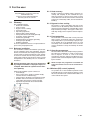
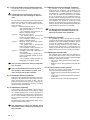
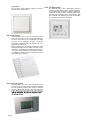
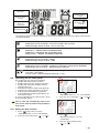
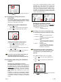
ComfoAir 550 Luxe User Manual All rights reserved. This manual has been compiled with the utmost care. The publisher cannot be held liable for any damage caused as a result of missing or incorrect information in this manual. In case of disputes the Dutch version of these instructions will be binding. EN - II Table of Contents Preface ............................................................................................................................................................ 1 1 2 INTrodUCTIoN ............................................................................................................................................. 1 1.1 Guarantee and liability ........................................................................................................................ 1 1.1.1 General ...................................................................................................................................... 1 1.1.2 Guarantee conditions ............................................................................................................... 1 1.1.3 Liability ...................................................................................................................................... 1 1.2 Safety .................................................................................................................................................. 2 1.2.1 Safety regulations ..................................................................................................................... 2 1.2.2 Safety provisions and measures .............................................................................................. 2 1.2.3 Pictograms used....................................................................................................................... 2 For ThE USEr ............................................................................................................................................... 3 2.1 Glossary ............................................................................................................................................... 3 2.1.1 Balanced ventilation ................................................................................................................. 3 2.1.2 Heat recovery............................................................................................................................ 3 2.1.3 Bypass for free cooling ............................................................................................................ 3 2.1.4 Frost protection ........................................................................................................................ 3 2.1.5 Open fire programme ............................................................................................................... 3 2.1.6 Wireless (RF) control (optional) ................................................................................................ 3 2.1.7 Non-powered extractor hood (optional) .................................................................................. 4 2.1.8 Preheater element (optional) .................................................................................................... 4 2.1.9 Afterheater (optional) ................................................................................................................ 4 2.1.10 Geothermal heat exchanger (optional) .................................................................................... 4 2.1.11 Enthalpy (optional) .................................................................................................................... 4 2.1.12 Analogue input (0-10V) ............................................................................................................. 4 2.1.13 Luxury versions extra options.................................................................................................. 4 2.2 Available operating devices ............................................................................................................... 5 2.2.1 3-position switch ...................................................................................................................... 5 2.2.2 Bathroom switch ...................................................................................................................... 5 2.2.3 CO2 sensor ................................................................................................................................ 5 2.2.4 CC Luxe panel .......................................................................................................................... 6 2.2.5 CC Ease panel .......................................................................................................................... 6 2.3 operating the CC Ease panel............................................................................................................. 7 2.3.1 Setting the date and time ......................................................................................................... 7 2.3.2 Reading and setting the comfort temperature ........................................................................ 8 2.3.3 Reading and setting the ventilation volume ............................................................................ 8 2.3.4 Switching Boost on .................................................................................................................. 9 2.3.5 Switching the extractor hood on/off (optional) ....................................................................... 9 2.3.6 Switching the supply and exhaust fan on/off.......................................................................... 9 2.3.7 Setting a personal ventilation programme ............................................................................ 10 2.3.8 Setting additional ventilation programmes/ options in the P menus ................................... 10 2.3.9 P menus for the user .............................................................................................................. 12 III - EN 3. 2.4 Maintenance by the user .................................................................................................................. 14 2.4.1 Cleaning or replacing the filters ............................................................................................. 14 2.4.2 Cleaning the valves (in your dwelling) ................................................................................... 14 2.5 Malfunctions ...................................................................................................................................... 15 2.5.1 Malfunction alerts on digital operating devices .................................................................... 15 2.5.2 3-position switches with malfunction indicator .................................................................... 15 2.5.3 What to do in the event of a malfunction .............................................................................. 15 2.6 End of useful life................................................................................................................................ 15 EEC declaration of conformity ................................................................................................................... 16 EN - IV Preface 1.1 Carefully read this manual before use. This manual provides all the information required for safe and optimal, operation of the ComfoAir 550 Luxe. It is also intended as a reference for servicing, so that this can be carried out in a responsible manner. The device is subject to continuous development and improvement. As a result, the ComfoAir 550 Luxe may slightly differ from the descriptions. NOTE This manual has been compiled with the utmost care. However, no rights can be derived from it. In addition, we at all times reserve the right to change the contents of this manual, without prior notice. 1 Introduction The device's name is ComfoAir 550 Luxe. In the following it will be referred to as ComfoAir. The ComfoAir is a balanced ventilation system with heat recovery in order to create healthy, balanced and energy-efficient ventilation in houses. The ComfoAir has a CE marking on the identification plate. The identification plate can be found on top of the ComfoAir. Warranty and liability 1.1.1 General The sales and warranty conditions for companies in the metal, plastic and technology industries, which apply to the ComfoAir, have been deposited with the Clerk of the District Courts of the Hague on 19th October 1998, under number 119/1998. 1.1.2 Guarantee conditions The ComfoAir is covered by a manufacturer’s warranty for a period of 24 months after fitting up to a maximum of 30 months after the date of manufacture. Warranty claims may only be submitted for material faults and/or construction faults arising during the warranty period. In the case of a warranty claim, the ComfoAir must not be dismantled without written permission from the manufacturer. Spare parts are only covered by guarantee, if they were supplied by the manufacturer and have been installed by an approved installer. The warranty becomes invalid if: • The guarantee period has elapsed; • The device is used without filters; • Parts are used that have not been supplied by the manufacturer; • Non-authorised changes or modifications have been made to the unit. 1.1.3 Liability The ComfoAir has been designed and manufactured for use in “balanced ventilation systems”. Any other use is deemed unintended use and can lead to damage to the ComfoAir or personal injury, for which the manufacturer cannot be held liable. The manufacturer is not liable for any damage originating from: • Non-compliance with the safety, operating and maintenance instructions in this manual; • The use of components not supplied or recommended by the manufacturer. Responsibility for the use of such components lies entirely with the installer; • Normal wear and tear. 1 - EN 1.2 Safety 1.2.1 Safety regulations Always comply with safety regulations in this manual. Non-compliance with the safety regulations, warnings, notes and instructions in this manual can cause personal injury or damage to the ComfoAir. • The ComfoAir may only be installed, connected, rendered operational and maintained by an appropriately approved installer, unless otherwise indicated in this manual; • Installation of the ComfoAir must be carried out in accordance with the general and locally applicable construction, safety and installation instructions of the local council, electricity and water boards or other agencies; • Observe the safety regulations, warnings, comments and instructions as prescribed in this manual at all times; • Keep this manual with the ComfoAir throughout its life; • Instructions with regard to cleaning or replacing the filters of the intake and exhaust valves must be carefully observed; • The specifications stated in this document may not be changed; • Modifying the ComfoAir is not allowed; • The ComfoAir is only suitable for connetion to 230V 50Hz mains; • It is recommended to take out a maintenance contract so that the device is checked on a regular Basic. The supplier can provide a list of registered installers nearby. EN - 2 1.2.2 Safety provisions and measures • • The ComfoAir cannot be opened without using tools; It should not be possible to touch the fans, therefore ducting must be connected to the ComfoAir at a minimum duct length of 900mm. 1.2.3 Pictograms used The following pictograms are used in this manual: Point of attention. Risk of: - damage to the device; - performance of the device is compromised if instructions are not observed carefully. Risk of personal injury to the user or installer. 2 For the user 2.1.2 heat recovery Congratulations, you are the owner of a ComfoAir 550 Luxe, an heat recovery unit from Zehnder. We wish you lots of comfort. 2.1 Glossary The ComfoAir features: • Balanced ventilation; • Heat recovery; • Bypass for free cooling; • Frost protection; • Open fire programme; • Wireless (RF) control (optional) • Non-powered extractor hood (optional) • Preheater element (optional); • Afterheater (optional); • Geothermal heat exchanger (optional); • Analogue input (0-10V); • Enthalpy (optional). A concise explanation of these concepts/features is given in the paragraphs below. 2.1.1 Balanced ventilation The ComfoAir is a balanced ventilation system. Balanced ventilation means that pollutants from the kitchen, the bathroom, the toilet(s) and possibly the storage room are extracted, while the same amount of fresh air is blown into the living room and bedrooms. Gaps under or near the doors ensure a good through-flow in the dwelling. The air circulation is in balance. Ensure that these gaps are never obstructed by draught excluders or deep-pile carpet, for example. Otherwise the system will not function optimally. A balanced ventilation system consists of: • ComfoAir (A); • Duct system for the supply of outdoor air (B) and the exhaust of indoor air (C); • Supply valves in the living room and bedrooms (D); • Exhaust valves in the kitchen, bathroom, the toilet and (if present) the storage room (E); • Optional non-powered extractor hood with 3-position switch (F). B Besides ensuring a healthy balance between incoming and outgoing air, the ComfoAir also provides the benefits of heat recovery. Heat recovery means that heat from the extracted air is transferred to the fresh, and usually colder, air from outside the building. 2.1.3 Bypass for free cooling The bypass is often used during hot days in the summer season. By allowing colder outside air in at night, the indoor temperature of the dwelling can be kept low during hot days. The bypass works automatically: simply set the required comfort temperature. 2.1.4 Frost protection The ComfoAir is also fitted with a frost protection device. This is an automatic protective system that temporarily reduces (or even briefly stops) the supply of outdoor air to the ComfoAir if there is a risk of freezing in the ComfoAir. This can occur in the event of moderate to sharp frost during the winter months. 2.1.5 Openfireprogramme The ComfoAir is fitted with an Open fire programme. The Open fire programme is used in houses that have a fireplace, as there is a risk of air being sucked back from the chimney. The Open fire programme works automatically but requires activation by the installer. While the Open fire programme is activated the supplyandexhaustfancannotbeturnedoffmanually. 2.1.6 Wireless (rF) control (optional) It is possible to set the ventilation positions of the ComfoAir with one or more wireless switches. To do this the ComfoAir needs a build in RF module or a connected CC Ease panel. C A D D E D E D E F 3 - EN 2.1.7 Non-powered extractor hood (optional) It is possible to fit the ventilation system with a nonpowered extractor hood. A powered extractor hood may nevery be connected to the same ducting as the ComfoAir. The non-powered extractor hood is mounted above the hob and removes undesirable cooking smells. There are four types of non-powered extractor hoods available: • Type 1 g Mechanical on/off switch. - The exhaust valve is operated by turning the on/off switch. - The ventilation setting must be set with the ComfoAir switch; • Type 2 g Electrical on/off switch. - The exhaust valve is operated by pushing the on/off switch. - The ventilation setting must be set with the ComfoAir switch; • Type 3 g Electrical on/off switch with connection to the ComfoAir. - The exhaust valve is operated by pushing the on/off switch. - The ventilation setting switches automatically to an "High" setting; • Type 4 g 3-position switch with connection to the ComfoAir. - The exhaust valve is operated by selecting a ventilation setting on the extractor hood. - The ventilation setting switches automatically to an "High" setting. The 3-position switch can also be integrated in a CC-Luxe. The non-powered extractor hood is part of the ducting of the ventilation system, and does not form part of the ComfoAir. 2.1.8 Preheater element (optional) Fitting the optional Preheater element in the ComfoAir gives the added bonus that balanced ventilation remains intact for longer. In that case, the supply of cold outside air no longer needs to be reduced (so soon). The Preheater element is activated and deactivated automatically. 2.1.9 Afterheater (optional) It is possible to fit the ventilation system with an Afterheater. The Afterheater ensures that the supply air is heated further before it enters any living areas. The advantage of a Afterheater is that the supply air can be instantly released into the house at the set comfort temperature. That offers additional comfort. The Afterheater works automatically: simply set the required comfort temperature. The Afterheater is part of the ducting of the ventilation system, and does not form part of the ComfoAir. EN - 4 2.1.10 Geothermal heat exchanger (optional) It is possible to fit the ventilation system with a geothermal heat exchanger. The geothermal heat exchanger ensures that outside air is supplied to the dwelling at a constant temperature. Therefore, in the event of subzero temperatures, the outside air can be heated up by the geothermal heat exchanger, prior to releasing it into the house through the ComfoAir. Alternatively, in the event of hot summer conditions, the outside air can also be cooled down by the geothermal heat exchanger, prior to releasing it into the house through the ComfoAir. The geothermal heat exchanger is automated. TheGeothermalheatexchangerispartof theductingoftheventilationsystem,and doesnotformpartoftheComfoAir. 2.1.11 Enthalpy (optional) It is possible to fit the ComfoAir with an enthalpy exchanger. An enthalpy exchanger helps to regulate humidity levels in the dwelling. In addition to heat recovery, the enthalpy exchanger also ensures moisture recovery. Moisture recovery means that moisture from extracted air is transferred to the supply air sourced from outside the dwelling. An enthalpy exchanger is also less sensitive to freezing. 2.1.12 Analogue input (0-10V) The ComfoAir Luxe is fitted with four analogue inputs (0-10V). These inputs can be used to connect various sensors or control systems to the ComfoAir. Examples of the options include: • CO2 sensor; flow regulation using carbon dioxide levels; • Moisture sensor; flow regulation using moisture levels; 2.1.13 Luxury version extra options Besides the options stated earlier, the ComfoAir Luxe also offers the following options: • Connection for remote (fixed-line) malfunction alerts; • Connection for remote (fixed-line) deactivation of the fans; • Connection for filter alert for external filters. 2.2 Available operating elements The ComfoAir is fitted with the following operating elements: • 3-position switch; • 3-position switch with malfunction indicator; • Wireless 3-position switch; • Wireless 3-position switch with malfunction indicator; • 3-position switch on the non-powered extractor hood; • Bathroom switch to temporarily select the highest ventilation position; • CO2 sensor; • CC Luxe panel; • CC Ease panel. A concise explanation of these operating elements is given in the paragraphs below. 2.2.1 3-position switch A 3-position switch can be used to set the ventilation positions of the ComfoAir. One or multiple 3-position switches can be fitted in the house (e.g. in the kitchen). The following types of switches can be used: • Type 1 g Standard 3-position switch; • Type 2 g 3-position switch with malfunction and filter alerts indicator; • Type 3 g Wireless 3-position switch (RF) • Type 4 g Wireless 3-position switch (RF) with malfunction and filter alerts indicator; • Type 5 g 3-position switch integrated on a motor free extractor hood. Awireless3-positionswitchneedtoberetunedtotheComfoAirifaGeneralResetis given. 1 2 3 Type 1 Type 2 Setting the ventilation using 3-position switch(es) Type 4 A 3-position switch can be used to set 3 different ventilation positions. • Position 1 g Low. - Use for low ventilation levels. • Position 2 Normal. - Use when present and no extra ventilation is needed. • Position 3 High. - Use during cooking, showering and when additional ventilation is needed. • Timer Temporary High - Use during cooking, showering and when additional ventilation is needed for a short time. The wireless 3-position switches have an seperated button for the Timer. After the timer delay the ComfoAir will return to the ventilation setting which was active before the timer function was activated. To use the Timer function with a wired 3-position switch choose setting 3 and immediately return to the setting you want after the timer delay. The CC Ease panel and CC Luxe panel have an integrated type 2 3-position switch. Next to the standard 3 ventilation settings the CC Ease panel and CC Luxe panel also have an additional ventilation setting: • Position A Absent - Use when absent. At setting A, the house is ventilated using the minimum prescribed ventilation volume. If multiple position switches are available in the house, the ComfoAir will switch to the highest ventilation setting unless overruled by an automated software programme. 2.2.2 Bathroom switch A bathroom switch can be used to temporarily set the ComfoAir in the highest ventilation level. This switch is mostly fitted in the bathroom to extract any excess moisture after showering, as soon as possible. The bathroom switches vary widely in model and are therefore not illustrated here. If required, the bathroom switch can be turned on and off using a time delay entered via a digital operating device. delay timer This ensures that the ComfoAir does not switch on at the highest setting when activated, but first waits for the delay timer to run its course. If the bathroom switch is deactivated during the delay timer period, then the ComfoAir will remain at its current ventilation setting and not switch to the highest setting. The delay timer does not work with all types of bathroom switches (e.g. pulse switches). In that case, leave the delay timer at 0. overrun timer This ensures that the ComfoAir does not switch back to the normal (or previous) setting when deactivated, but first waits for the overrun timer to run its course. Once the programmed overrun timer is complete, the ComfoAir returns to the normal (or previous) ventilation setting. If the bathroom switch is turned off within the programmed delay timer period, then the overrun function will be terminated. 5 - EN Light switch The functions of the bathroom switch can also be integrated into a light switch. 2.2.3 Co2 sensor The ComfoAir Luxe can also be operated using a CO2 sensor. A CO2 sensor measures the CO2 levels in the room where it is placed. When the CO2 sensor is set on 'automatic' the CO2 sensor will control the ventilation setting according to the ventilation need in the room. When the CO2 levels are high the ventilation setting will automatically increase. When the CO2 levels are low the ventilation setting will automatically decrease. It is also possible to use the CO2 sensor as a standard 3-position switch. The CO2 levels in the room will then by ignored. 2.2.4 CC Luxe panel The ComfoAir Luxe can be operated by means of a CC Luxe panel, which can be ordered separately. The CC (Comfort Control) Luxe panel is a digital operating device which can be mounted on the wall in the living room and from there communicates with the ComfoAir. The CC Luxe panel is operated via a touch screen. EN - 6 2.2.5 CC Ease panel The ComfoAir Luxe can be operated by means of a CC Ease panel, which can be ordered separately. The CC (Comfort Control) Ease panel is a digital operating device which can be mounted on the wall in the living room and from there communicates with the ComfoAir. The following overview summarizes the information that will be displayed. Day and time Supply air and/or exhaust air OPEN or CLOSED Automatic or manual ventilation Geothermal heat exchanger (EWT), afterheater [ ]and/ or bypass open [ ] or closed. Signal to replace internal (I) or external (E) filter Actual ventilation setting (Activated extractor hood Actual temperature, selection or setting ) The CC Ease panel has a number of buttons to operate the ComfoAir and to enter the settings. These buttons are illustrated below. This button allows you to switch to the highest ventilation setting. - Press for less than 2 seconds¨Extractor hood ON or OFF (optional). - Press for longer than 2 seconds¨ Boost setting ON. This button allows you to switch between supply/exhaust. - Press once¨SUPPLY OFF (and EXHAUST ON). - Press twice¨EXHAUST OFF (and SUPPLY ON). - Press 3 times¨SUPPLY and EXHAUST both ON. With this button you can read or set the comfort temperature. - Press for less than 2 seconds¨READ. - Press for longer than 2 seconds¨SET. This button allows you to programme two settings. - Press for less than 2 seconds¨Programme ventilation setting (AUTO / MANUAL). - Press longer than 2 seconds¨Programme date and time. This button allows you to programme different settings: - In P menu¨Set values. - In main screen¨Enter ventilation setting (A, 1, 2, 3). 2.3 operating the CC Ease panel The CC Ease panel is used for the following: • Reading and setting the day and time; • Reading and setting the comfort temperature; • Reading and setting the ventilation volume; • Switching Boost on; • Switching the extractor hood on/off (optional); • Switching the supply and exhaust fan on/off; • Setting a personal ventilation programme; • Setting additional ventilation programmes/ options in the P menus. A concise explanation of the above listing is given in the paragraphs below. 3. Press " ". - Wait until the hour, e.g. “ 12 ”, starts blinking. 4. Select the correct hour using " " or " The CC ease will automatically return to the main screen when no buttons are pressed for 30 seconds. 2.3.1 Setting the date and time 1. Press " " longer than 2 seconds. - Wait until the day, e.g. “Sa”, starts blinking. 2. Select the correct day using " " or " ". 5. Press " ". - Wait until the minutes, e.g. " 00 ", start blinking. 6. Select the correct minutes using " " or " ". 7 - EN ". In the event a required ventilation setting is being overridden by a time delay function (such as the bathroom switch overrun timer). a 't' is displayed in the bottom right-hand corner of the CC Ease panel. In the event a required ventilation setting is being overridden by a signal from a sensor (such as a CO2 sensor), an 'A' is displayed in the bottom right-hand corner of the CC Ease panel. 7. Press " " to store the settings and return to the main screen. 2.3.2 reading and setting the comfort temperature The comfort temperature can be read, but also set to the desired indoor temperature. By this temperature the ComfoAir will determined if free cooling with the use of the bypass is desired. Reading the comfort temperature 1. Press " " briefly. - Wait until the comfort temperature appears. 2. Press " " to return to the main screen. Setting the ventilation volume The ventilation volume can also be set manually by increasing or decreasing it. A total of 4 ventilation volumes/levels can be set. They are: • Setting A ¨ Absent. - Use when absent. At setting A, the house is ventilated using the minimum prescribed ventilation volume. • • • Setting the comfort temperature 1. Press " " longer than 2 seconds. - Wait until the comfort temperature, e.g. “ 20.0 ” starts blinking. 2. Select the desired comfort temperature using " " or " ". 3. Press and briefly hold " " to store the set- tings and return to the main screen. It is best to set the comfort temperature at the same temperature as the room thermostat (of the Central Heating system) • Setting 1 ¨ Low. - Use for low ventilation levels. Setting 2 ¨ Normal. - Use when present and no extra ventilation is needed. Setting 3¨High. - Use during cooking, showering and when additional ventilation is needed. Boost ¨ Temporary High - Use during cooking, showering and when additional ventilation is needed for a short time. The ComfoAir will switch to the highest ventilation position set in the house unless overruled by an automated software programme. The ventilation volume can be set as follows: 1. Press " " to increase the ventilation vol- ume. 2.3.3 reading and setting the ventilation volume 2. Press " " to decrease the ventilation vol- ume. reading the ventilation volume The current ventilation volume, e.g. “2 ”, will always be displayed on the CC Ease panel. Normally the ComfoAir regulates the required ventilation volume automatically according to a preset personal ventilation programme. During automatic ventilation mode “AUTo” will be displayed on the CC Ease panel. In addition to showing the programmed ventilation setting, the CC Ease panel also displays whether a temporary control system (such as a CO2 sensor or a bathroom switch) is overriding the ventilation setting. EN - 8 During manual ventilation, the CC Ease panel will not display “AUTo”, but “MANUAL”. 8 - EN 3. Press " " to return to automatic ventilation. While the overrun timer for the extractor hood is activated '3t' will be displayed and the ventilation setting will not tune down. The overrun timer can be deactivated by pressing " ", " " or " ". 2.3.4 Switching Boost on 1. Press“ ” longer than 2 seconds. - Wait until '3t' appears. 2.3.6 Switching the supply and exhaust fan on/off While the Open fire programme is activated the supply and exhaust fan can not be turned off manually. Once the programmed time delay is complete, the ComfoAir automatically switches back to the previous ventilation setting. 1. Press " " once (first time) to switch off the supply fan. The Boost timer can be deactivated by pressing " ", " " or " ". 2.3.5 Switching the extractor hood on/off (optional) 1. Press " ". - Wait until the ventilation setting switches to setting 3 and the symbol for the extractor hood appears. This mode can be used when the windows are open during the summer. In that case, fresh air is not supplied through the supply fan, but through the open windows. 2. Press " " again (second time) to switch the exhaust fan off (and simultaneously switching the supply fan on). 2. Press " " to switch the extractor hood off. - After switching off the extractor hood, the symbol for the extractor hood will disappear from the CC Ease panel. 3. Press " " again (third time) to switch the supply and exhaust fans on again. 9 - EN Bear in mind that switching off the supply or exhaust fan will temporarily immobilize your balanced ventilation system. 2.3.7 Setting a personal ventilation programme 8. Press " ". – Wait until the minutes , e.g. " 00 ", starts blinking. 9. Select the desired start time in minutes using " " or " ". The ComfoAir has a factory default ventilation setting (setting 2). If wanted, you can change the default ventilation setting to suit your individual situation. For example a weekday and weekend programm. The ventilation volume can be changed/set as follows: 1. Press " " and " " for two seconds si- multaneously. - Wait until the ventilation programme appears. 2. Programme the desired day or series of days. " or " ". - Select the desired option using " You can choose from: – Weekend: “SaSu”; – Working week: “MoTuWeThFr”; – Week: “SaSuMoTuWeThFri”; – Separate days: “Sa”, “Su”, “Mo”, “Tu”, “We”, “Th” and “Fri”. 10. Press " ". – Wait until the ventilation setting e.g. " 3 ", starts blinking. 11. Select the desired ventilation level using " or " " ". When "d" is selected the selected programme position will be deleted. 12. Press " " to save the settings and return to the main screen. 13. Programme the next ventilation programme if required. Up to 8 program positions can be programmed. - Repeat steps 1 to 12. 4. Press ” “. - Wait until the programme position, e.g. "1", starts blinking. 5. Select the desired programme position using " " or " ". The default ventilation setting (setting 2) will be loaded again if a General Reset is given. 2.3.8 Setting additional ventilation programmes/ options in the P menus. Some P menus in the CC Ease panel can be used to: • Read the status of various ventilation programmes; • Set ventilationsettings for the extractor hood; • Set time delays for various ventilation programmes. 6. Press " ". - Wait until the hour, e.g. “ 7 ”, starts blinking. 7. Select the desired start time in hours using " " or " ". The user can only access P menus P1, P2 and P9 to set additional programmes. The remaining P menus (P3 to P8) are for use by the installer only. Accessing the P menus 1. Press " " and " " for two seconds simultaneously. - Wait until "P 2" appears on the display. 2. Select the desired P sub-menu using " " or " EN - 10 ", e.g., P menu “2 ". 3. Press " ". 4. Select the desired P sub-menu using " " ", e.g., P sub-menu " 23 ". 5. Press " ". " or EnteringsettingsinPmenus The minimum and maximum values for the available parameters are preset in the software. 6. Select a new value for the programme using " " or " ". 7. Press " " to store the settings. 8. Repeat steps 4 to 7 to set multiple parameters in succession. Or Press " " to return to the P menu so steps 2 to 7 can be repeated. 9. Press " " twice to return to the main screen. Only in the P2 menus settings can be altered. The other P-menus (P1 and P9) can only be read. LeavingReadingmenu • Press " " (instead of " ") ad step 7. 11 - EN 2.3.9 P menus for the user Menu P1 ¨ Status of programmes Status Submenu P10 P11 P12 P13 P14 P15 P16 P19 description Activated Is menu 20 currently active? Is menu 21 currently active? Is menu 22 currently active? Is menu 23 currently active? Is menu 24 currently active? Is menu 25 currently active? Is menu 26 currently active? Is menu 29 currently active? Yes (1) / No (0) Yes (1) / No (0) Yes (1) / No (0) Yes (1) / No (0) Yes (1) / No (0) Yes (1) / No (0) Yes (1) / No (0) Yes (1) / No (0) Menu P2 ¨ Setting time delays Time delay values Sub-menu P20 (Optional) description Overrun timer for the extractor hood programme. • ’x’ minutes after operating the extractor hood switch the ComfoAir reverts back to the normal setting. P21 Delay timer for the bathroom switch (to (Optional) switch to high position). • 'x' minutes after operating the bathroom Note: switch, the ComfoAir switches to the high setting. only applies to systems fittedwithacordedswitch - Low voltage input and a second switch in the bathroom. P22 Overrun timer for the bathroom switch (to (Optional) switch to normal position). • 'x' minutes after operating the bathroom switch, the ComfoAir switches back to the Note: normal setting. only applies to systems fittedwithacordedswitch - Low voltage input and a second switch in the bathroom. P23 Overrun timer for ventilation position 3 (us(Optional) ing a wired 3-position switch). • If ventilation setting 3 (high) is switched Note: on briefly (< 3 sec), the ComfoAir will only applies to systems switch to the high setting for 'x' minutes and then automatically returns to the norfittedwithahardwired mal setting. 3-position switch. P24 EN - 12 Minimum 0 Min. MaxiGeneral mum reset 180 Min. 0 Min. 0 Min. 15 Min. 0 Min. 0 Min. 120 Min. 30 Min. 0 Min. 120 Min. 0 Min. If any 3-position switch is operated during this lagging time the ComfoAir will instantly revert to the ventilation position as set at that time. 10 weeks 26 weeks Filter warning • 'x' weeks after cleaning the filters the "filter dirty" alert will reappear. 16 weeks Time delay values Sub-menu description P25 Overrun timer for ventilation setting 3 (using "). " Note: • After pressing " " briefly (< 2 sec.), the OnlyappliestosystemsfitComfoAir will switch to the high setting for ted with an rF switch. ‘x’ minutes and then automatically returns to the normal setting. If any 3-position switch is operated during this lagging time the ComfoAir will instantly revert to the ventilation position as set at that time. P26 Overrun timer for ventilation setting 3 " using ". Note: • After pressing " " continuously (> 2 Onlyappliestosystemsfitsec.), the ComfoAir will switch to the high ted with an rF switch. setting for ‘x’ minutes and then automatically returns to the normal setting. If any 3-position switch is operated during this lagging time the ComfoAir will instantly revert to the ventilation position as set at that time. P27 Time for the Boost setting. ]" on the CC Luxe • After pressing "[ Note: panel or after pressing “ ” continuosly Onlyappliestosystemsfit(>2 sec.) on the CC Ease panel, the Comted with a CC Ease panel or foAir will switch to the high setting for 'x' CC Luxe panel. minutes and then automatically returns tot the NORMAL setting P29 (Optional) If any 3-position switch is operated during this lagging time the ComfoAir will instantly revert to the ventilation position as set at that time. Setting the extractor hood ventilation levels. • When the extractor hood is switched on the extractor hood ventilation settings can be set x-% higher than the corresponding 'normal' ventilation levels. Minimum 1 Min. Maximum 20 Min. General reset 10 Min. 1 Min. 120 Min. 30 Min. 0 Min. 120 Min. 30 Min. 1% 99% 10% Menu P9 ¨ Status of programmes (from menu P5 and P6 additional programmes) Status Sub-menu P90 P91 P92 P93 P94 P95 P96 P97 description Open fire programme active? Bypass Open? Geothermal heat exchanger valve Open? Afterheater on? Analogue input (0-10V) active? Frost protection or Preheater active? Extractor hood on? Enthalpy programme active? Activated Yes (1) / No (0) Yes (1) / No (0) Yes (1) / No (0) Yes (1) / No (0) Yes (1) / No (0) Yes (1) / No (0) Yes (1) / No (0) Yes (1) / No (0) 13 - EN $ 2.4 Maintenance by the user The following maintenance must be carry out by the user: • Cleaning or replacing the filters; • Cleaning the valves (in the dwelling). A concise explanation of these maintenance activities is given in the paragraphs below. % Failure to carry out (periodic) maintenance on the ComfoAir ultimately compromises the performance of the ventilation system. 5. Slide the new filters back into the ComfoAir. 6. Refit the handles (A) to the ComfoAir. 7. Reconnect the power to the ComfoAir. To clean... 2.4.1 Cleaningorreplacingthefilters Vacuum the filters (B) with a vacuum cleaner in$ of replacing them with new filters. stead $ If so indicated on the digital operating device, you must clean or replace the filters. Replace the filters (at least) every six months and clean the filters every 2 or 3 months. When using the ComfoAir for the first time, it is recommended to clean the filters (and valves) first. During the construction phase the ventilation system could have become dirty with building dust. • “ filter I ” ¨ The internal filters must be cleaned or replaced. • “ filter E ” ¨ The external filters must be cleaned or replaced. The CC Ease panel will display one of the above filter warnings. 2.4.2 Cleaning the valves (in your dwelling) The ventilation system may be fitted with the following valves: Exhaust valve (STB) Exhaust valve (STB) ( Exhaust valve (STC) Exhaust valve (STC) ) The internal filters are included in the standExhaustof valve valve (STC) ard configuration the(STB) ComfoAir. Exhaust The external filters (optional) is part of the ducting of the ventilation system, and does not form part of the ComfoAir. Exhaust valve (STV) Exhaust valve (STV) Exhaust valve (STK) Exhaust valve (STK) To replace ... 1. Press “ ” on the CC Ease panel for at least Exhaust valve (STV) Exhaust valve (STK) 4 seconds until the filter warning disappears. 2. Disconnect the power from the ComfoAir. 3. Remove the handles (A) from the ComfoAir A A 4. Remove the old filters (B) from the ComfoAir EN - 14 Supply valve (STH) You must clean the valves (at least) twice a year: 1. Mark the setting of the valve; 2. Remove the valve from the wall or ceiling; 3. Clean the valve in a solution of soap and warm water; 4. Rinse the valve thoroughly and wipe dry; 5. Place the valve back WITH EXACTLY THE SAME SETTING (and IN THE SAME HOLE); 6. Repeat this procedure for the other valves. About the valve settings... The ventilation air is supplied and discharged by means of valves. Gaps near doors in the dwelling ensure that the air flows in the right direction. In order to ensure that the correct ventilation volumes are maintained in the rooms, the following must be observed: • do not seal the gaps; • do not change the settings of the valves; • do not replace the valves with one another. The installer will have set all the valves to ensure the optimum performance of the ventilation system. Therefore, do not change the setting of the valves. Supply valve (STH) Supply valve (STH) After cleaning, make sure that all valves are placed back with the same setting (and in exactly the same ventilation hole in the wall or ceiling) AT ALL TIMES. Otherwise, system performance will be compromised. 2.5 2.5.3 What to do in the event of a malfunction In the event of a malfunction, contact the installer. Note down the malfunction code that appears on the digital operating device. Make a note of your ComfoAir type. This is given on the identification plate on the top of the ComfoAir. The system should not be disconnected from the power supply, unless the ComfoAir must be taken out of service due to a serious malfunction, or for filter cleaning/replacement or any other compelling reasons. Malfunctions Malfunctions in the ComfoAir are reported as follows: • The malfunction alert appears on the CC Ease panel; • The malfunction alert appears on the CC Luxe panel; • The malfunction indicator on the 3-position switch lights up; A concise explanation of methods of reporting malfunctions is given in the paragraphs below. If the ComfoAir is disconnected from the power supply, mechanical ventilation of the dwelling will cease. This can lead to a buildup of moisture and results in problems with mould. Long-term deactivation of the ComfoAir must therefore be prevented. 2.5.1 Malfunction alerts on the digital operating device IftheComfoAirisinstalledinanareawitha higher average humidity (such as bathroom or toilet) the probability of condensation on theoutsideoftheComfoAirishigh.Thisisa normalphenomenon,similartocondensation onawindow,onwhichnoactionisneeded. In the event of a malfunction, the corresponding malfunction code will be displayed on the digital operating device of the ComfoAir. Please refer to the malfunction overview to find out the meaning of the relevant malfunction alert. 2.6 2.5.2 3-position switch with malfunction indicators End of useful life Consult with the supplier about what should be done with the ComfoAir at the end of its useful life. If the ComfoAir cannot be returned to the supplier, avoid disposing of it with the domestic waste, and ask your local council about the options for recycling the components or processing the materials in an environmentally friendly manner. Furthermore, do not dispose of batteries from the wireless (RF) switches with the normal waste, but bring them to the specially designated disposal locations. The 3-position switches that are fitted with a malfunction indicator show when a malfunction or filter dirty alert has occurred. Depending on the type of the 3-position switch, this is done in one of the following two ways: • 3-position switch with malfunction indicator. In the event of a malfunction or filter dirty alert the indicator lights up; • Wireless 3-position switch with malfunction indicator. The malfunction indicators will light up once this 3-position switch is used. One indicator will light up green to indicate communication has been established. Subsequently, in the event of a malfunctionor filter dirty alert both indicators will flash red 3 times. After that, both indicators will light up green once more. 15 - EN 3 EEC declaration of conformity Zehnder Group Nederland B.V. Lingenstraat 2 8028 PM Zwolle-NL Tel.: +31 (0)38-4296911 Fax: +31 (0)38-4225694 Company register Zwolle 05022293 EEC declaration of conformity Machine description : heat recovery units: ComfoAir 550 series Complies with the following directives : Machinery Directive Low Voltage Directive EMC Directive Zwolle, 19 March 2010 Zehnder Group Nederland B.V. E. van Heuveln, Managing Director EN - 16 (2006/42/EEC) (2006/95/EEC) (2004/108/EEC) © Zehnder Group Nederland B.V. 849050675-0711 latoren B.V. 849050582-0408 Zehnder Group Nederland B.V. Lingenstraat 2 8028 PM Zwolle Nederland Tel.: (038) 429 69 11 Fax.: (038) 422 56 94 Internet: www.jestorkair.nl E-mail: [email protected]