1
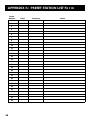
USER'S
GUIDE
RV-9900
RV-9950
AUDIO/VIDEO RECEIVER
Safety Information
WARNING
RISK OF ELECTRIC SHOCK
DO NOT OPEN
TO REDUCE THE RISK OF ELECTRIC SHOCK,
DO NOT REMOVE COVER (OR BACK). NO
USER SERVICEABLE PARTS INSIDE. REFER
SERVICING TO QUALIFIED SERVICE PERSONNEL.
This symbol indicates
"dangerous voltage" inside
the product that presents a
risk of electric shock or
personal injury.
This symbol
indicates important
instructions accompanying
the product.
Caution: To reduce the risk of electric shock, match
wide blade of plug to wide slot, fully insert.
Attention: Pour éviter les chocs électriques, introduire
la lame la plus large de la fiche dans la borne
correspondante de la prise et pousser jusqú au fond.
Operate audio/video receiver only on 120 volts, 60 Hz AC power (normal
house power).
FCC Regulations state that unauthorized changes or modifications to
this equipment may void the user’s authority to operate it.
WARNING
To reduce fire or shock
hazard, do not expose this
product to rain or moisture.
Table of Contents
First Things First ........................................................ 3
Operating the Receiver ........................................... 9
Tuning the Receiver ....................................................................... 10
Storing Stations in Memory ........................................................... 10
Preset Scanning .............................................................................. 11
Balancing the Speaker System ....................................................... 12
Using Swap Audio .......................................................................... 13
TOUR OF THE RECEIVER ................................................ 15
Front Panel ..................................................................................... 16
Front Panel Displays ....................................................................... 18
Remote Control .............................................................................. 19
Back Panel ...................................................................................... 24
Programming the Remote ................................... 25
Programming the Remote ............................................................. 26
Programming the Remote to Control a TV................................... 26
Programming the Remote to Control a VCR ................................ 28
Programming the Remote to Control An Audio Component .....30
Programming the Remote to Control a Cable Box ..................... 32
Programming the Remote to Control a Laserdisc Player ............ 34
Programming the Remote to Control A Satellite ........................ 35
Programming the AUX button on the Remote ............................ 35
Appendix A: Connecting Your Receiver ......... 37
Connecting a TV and a VCR ........................................................... 39
Connecting a Satellite Receiver ..................................................... 40
Connecting a Laserdisc Player ....................................................... 41
Connecting a Second VCR.............................................................. 42
Connecting a Camcorder or Video Camera .................................. 43
Connecting a Compact Disc Player ................................................ 44
Connecting a Tape Deck or Minidisc Player .................................. 45
Connecting Antennas .................................................................... 46
Connecting Speakers ..................................................................... 47
Appendix B: Speaker Placement ......................... 50
Appendix C: Troubleshooting Guide ............... 51
Appendix D: Care and Cleaning .......................... 52
Appendix E: FCC Information .............................. 53
Appendix F: Limited Warranty .......................... 54
Appendix G: Equipment Specifications ............ 55
Appendix H: Preset Station List Form .............. 56
Index .............................................................................. 57
1
2
First Things First
Hi, my name is kim …
The first section of this owner’s manual shows you how to
use your audio receiver for the first time. The next three
sections tell you about using the receiver’s controls and
programming the remote. Use the last sections of the
manual to connect your receiver to other components
and as a general reference. If you have a specific question,
refer to the table of contents or the index. Call RCA
Consumer Relations for further questions. (see back cover)
First Things First
2
Operating the Receiver
3
3
Tour of the receiver
4
Programming the Remote
➣
read the first four chapters
1
➣
...and I wrote this user manual along with the help of the
engineers, designers and product managers. We worked
hard to make sure that you have a rewarding experience
using this RCA A/V receiver.
PLEASE READ THE NOTES IN THE TEXT
The engineers and designers gave me some great tips
about this audio/video receiver. When a tip applies to the
information on a page, I included it in a note box at the
bottom of the page.
READ ME…
Note boxes like this one
contain helpful and interesting
information about using your
audio receiver.
3
First Things First
Step 1: Unpack the Receiver
Unpack the receiver and the accessories. The
accessories packed with the receiver include the
RCA Remote (CRK67A1), 4 AAA cell batteries, an
AM loop antenna, an FM “T” antenna, one paired
(red/white) stereo cable, one single (yellow) video
cable and Important Safeguards.
Step 2: Connect the Receiver
Before you plug in and turn on your audio/video
receiver, connect the receiver to the components
in your system and connect the speakers.
The next two sections show how to connect the
receiver to a TV and a VCR . If you are going to
connect the receiver to a laserdisc player or other
component, see Appendix A: Connecting the
Receiver.
For information on connecting your speakers, see
Appendix A: Connecting the Receiver. For two
suggestions on placing your speakers for the best
sound, see Appendix B: Speaker Placement.
4
First Things First
TV and VCR connection
(TV without Audio output Jacks)
This connection provides
• stereo or surround sound from TV
programs broadcast in stereo
If your TV has more than one video
input, make sure the VCR and VIDEO
buttons tune the TV to the same
channel that the receiver monitor
out is plugged into.
• stereo, surround sound or mono sound
from a VCR
• viewing one channel on TV while
recording another channel
Refer to the TV’s user’s guide for
more information.
To use this connection, you must
have
For additional video device
connections, refer to Appendix A.
• (1) paired (red/white) stereo cable
• (2) coaxial cables
CABLE
BOX
IN
OUT
OR
ANTENNA
To Connect
1. Connect the cables as shown in the
diagram to the right.
VCR
IN FROM ANT
IN
CH3
CH4
OUT
VIDEO
R
OUT TO TV
L
Using This Connection
To watch TV programs
TV
1. Turn off the VCR.
2. Press TV and tune to a channel.
CABLE /
ANTENNA
To watch or play a tape on the VCR
1. Press VCR1 on your remote
2. Press PLAY.
To record one program and watch another
1. Press VCR1 on your remote and tune to
a channel.
AUDIO
RECEIVER
VIDEO
VCR
IN
OUT
VIDEO
MONITOR
IN
OUT
2. Begin recording.
3. Make sure TV/VCR switch on the
VCR is set to TV.
TAPE
CD
IN
TV
VCR
OUT
IN
VIDEO
OUT
SUB
WOOFER
4. Press TV and tune to a channel.
AUDIO
5
First Things First
TV and VCR
(TV with Audio output Jacks)
This connection provides
• stereo or surround sound from TV
programs broadcast in stereo
If your TV has more than one video
input, make sure the VCR and VIDEO
buttons tune the TV to the same
channel that the receiver monitor
out is plugged into.
• stereo, surround sound or mono
sound from a VCR
• viewing one channel on TV while
recording another channel
Refer to the TV’s user’s guide for
more information.
To use this connection, you
must have
For additional video device
connections, refer to Appendix A.
• (1) paired (red/white) stereo cable
• (2) coaxial cables
CABLE
BOX
IN
OUT
OR
To Connect
1. Connect the cables as shown in the
diagram to the right.
VCR
ANTENNA
IN FROM ANT
IN
CH3
CH4
OUT
VIDEO
R
OUT TO TV
L
Using This Connection
To watch TV programs
TV
1. Turn off the VCR.
VIDEO
INPUT
2. Press TV and tune to a channel.
RIGHT
OUT AUDIO
S-VIDEO
To watch or play a tape on the VCR
IN
CABLE /
ANTENNA
L/
MONO
1. Press VCR1 on your remote
2. Press PLAY.
To record one program and watch
another
1. Press VCR1 on your remote and
tune to a channel.
AUDIO
RECEIVER
VIDEO
VCR
IN
TAPE
CD
IN
TV
VCR
OUT
IN
2. Begin recording.
3. Make sure TV/VCR switch on the
VCR is set to TV.
4. Press TV and tune to a channel.
6
VIDEO
AUDIO
MONITOR
OUT
VIDEO
OUT
SUB
WOOFER
First Things First
Step 3: Put Batteries in the Remote
1. Slide the battery compartment cover off the back of
the remote.
2. Insert the 4 AAA batteries, matching the + and - ends of
each battery with the symbols in the compartment.
3. Replace the cover.
Step 4: Plug in the receiver
Before you plug in the receiver, connect the other
components and speakers.
Plug the power cord in the wall outlet, matching the wide
blade of the plug with the wide slot in the outlet. Be sure to
insert the plug completely.
Step 5: Turn on the receiver
Press the POWER button on the receiver, the POWER button
on the remote or any device button on the remote.
Read on…
The next section tells you how to
operate the receiver. Then, read
the section that takes you on a
tour of the receiver and
remote control.
7
8
Operating the Receiver
If you have questions …
1 First Things First
➣
…about the front panel or remote control buttons as you
go through this section, refer to Chapter 3, Tour of the
Receiver.
2 Operating
the Receiver
➣
3 Tour of the receiver
➣
4 Programming the Remote
Important:
In order to safeguard your
hearing, turn the volume down
before turning on your receiver.
Also, unless otherwise specified,
the buttons mentioned in this
chapter are on the remote control.
9
Operating the Receiver
Tuning the Receiver
1. Push the FM/AM button on the receiver (or the AM•FM
button on the remote) to activate the tuner.
2. Press the FM/AM button on the receiver (or the AM•FM
button on the remote) again to select the FM or AM band.
Tuning
Press the FF on your remote button to move up the AM or FM
band.
Press the REW button on your remote to move down the AM
or FM band.
Auto Tuning
Use the AUTO feature to automatically search for stations of
sufficient strength.
Press AUTO on your receiver (or the INPUT•SEEK button on
your remote) to put the receiver into AUTO mode. “AUTO”
appears in the display. Press TUNING up or down button on
the receiver to search. The tuner finds and stops on the next
station whose frequency is strong enough to be received. To
continue the search, press TUNING up or down button again.
Storing Stations in Memory
You can store up to 30 AM and FM stations. These stations can
be stored in random order.
To Store a Station
1. Press the FM/AM button on the receiver (or the AM•FM
button on the remote) to turn on the receiver.
2. Select the band—FM or AM.
3. Select the station you want to store in memory using the
methods described above.
4. Press the PROGRAM button on the remote. “MEMORY”
blinks in the display. While “MEMORY” is blinking, press
number buttons on the remote for the station.
For stations 1, 2 or 3 press 0, then press 1, 2, or 3. For
stations 4 through 30, press the numbers directly.
10
If the Memory indicator on the
display turns off before you
preset your station selection,
press PROGRAM again.
If the receiver is disconnected
from its power source, the preset
stations are maintained in
memory for up to 7 days.
OPERATING the Receiver
To Play a Preset Station
Press the appropriate Preset Stations number. For stations 1,
2 or 3 press 0, then press 1, 2, or 3. For stations 4 through 30,
press the numbers directly.
Or, press CHAN UP on your remote to tune to the next preset
station or CHAN DOWN to tune to the previous preset
station.
Preset Scanning
Use the PRESET SCAN button on the receiver’s front panel to
review the preset stations stored in the tuner’s memory.
“PRESET” and the station’s location in memory appear in the
display. The tuner automatically scans all preset stations in
order, pausing at each one for approximately
5 seconds.
When the tuner reaches the station you want, press PRESET
SCAN to stop the scanning. If the scan is not interrupted, the
tuner reviews all preset stations in order, stopping at the
point where the scan began.
11
OPERATING the Receiver
Balancing the Speaker System
To reproduce sound effects as they were intended, the
speakers must be correctly balanced.
To balance the speakers using the test tone, all speakers must
be connected to your receiver. Your receiver must be in the
Dolby Pro Logic Surround or Dolby 3 Stereo Mode.
To balance the speakers
1. Press the TEST TONE button on the receiver front panel. The
front panel displays show the current settings as the receiver
generates “pink noise” and applies it automatically at
2-second intervals to the left main channel, center channel,
right main channel, and left and right rear channels
(simultaneously), in that order.
2. As the pink noise is generated, go to the spot in the room
where you are most likely to be when listening to your
system. The rear Surround sound and center speaker should
be adjusted to equal the level of output from the left and
right main speakers.
3. Make adjustments by pressing the REAR•CENTER button,
and then the + or -button on your remote control. The
output from the selected speaker(s) is adjusted accordingly.
The adjustments will be indicated on the receiver’s display as
they are made.
Each time you press the + or - button on your remote
control to adjust a channel, the receiver provides you with
2 more seconds of pink noise to that channel before moving
on to the next. Also, the front panel displays reflect your
adjustments.
4. Press the TEST TONE button again to end the test.
You may not need to check or adjust these levels again unless
you move your system, rearrange the speakers, or change your
preferred seating location in the room.
*Manufactured under license from Dolby Laboratories
Licensing Corporation.
“Dolby,” the double-D symbol
, and “Pro Logic” are
trademarks of Dolby Laboratories Licensing Corporation.
12
Fine tuning is best performed
with the remote control so that
adjustments can be made from
the viewing or listening area.
OPERATING the Receiver
Using Swap Audio
Swap audio lets you change the sound from the large picture
to the small picture when you are watching TV and using
picture-in-picture (PIP) with an external video source.
To Use Swap Audio
When you are watching TV and turn on PIP, you can turn on
another video source and swap the sound from the large
picture coming from the TV to the small picture coming from
the other video source.
1. Press TV on the remote to turn on the TV and put the
receiver in TV mode.
2. Press the PIP button. The empty PIP appears on the screen.
3. Activate a video source for the PIP. The picture from the
video source appears in the PIP.
4. Press TV.
5. Change to the TV channel you want to watch on the
large screen.
6. Press SWAP AUDIO to swap the sound between the large
picture and the small picture.
7. To swap the video between the large picture and the small
picture, use the SWAP PIP button on the remote.
If you swap the TV picture to the PIP and the other video
source to the large picture, you may not be able to swap
the audio.
To Change the Video Source and swap
the audio
If you want to change the video source for the PIP and want
to be able to use SWAP AUDIO:
1. Turn off PIP.
2. Change the video source to another video component
connected to the receiver.
3. Press TV to watch the TV.
4. Press PIP. The video source appears in the PIP. The video
from the TV appears in the large picture.
5. Press SWAP AUDIO to swap the audio as you want.
The Swap Audio feature may not
work with all TV brands with the
PIP feature.
If your TV has a PIP feature, see
the TV’s user’s guide for
instructions for using it.
13
14
Tour of the Receiver
Buttons and connections
1 First Things First
➣
This section describes the receiver’s controls
and connections, including:
• The front panel
• The front panel display
• The remote control
the Receiver
➣
• The back panel
2 Operating
3 Tour of the Receiver
➣
4 Programming the Remote
As you operate the receiver, use
the displays on the receiver’s
front panel and the on-screen
displays as references when you
select options and adjust the
sound to your satisfaction.
15
Tour of the Receiver
MASTER VOLUME
16
14
12
18
10
REMOTE
SENSOR
20
22
8
POWER
24
6
26
4
STANDBY/ON
PRESET SCAN
TUNING
AU TO
28
2
1
0
2
3
4
5
6
7
8
30
0
9
BALANCE
TREBLE
BASS
PHONES
CD
TAPE
FM/AM
TV
VCR
VIDEO
L
PRO LOGIC
SPEAKERS
3 STEREO
CENTER MODE
HALL
TEST TONE
Front Panel
AUTO Selects auto tuning mode or manual tuning mode.
BALANCE Adjusts the sound from the left and right speakers.
BASS Adjusts the bass listening level.
BYPASS Turns off the Surround circuitry. Sound is generated
without effects—conventional stereo.
CD Selects the CD player input.
CENTER MODE Lets you select a center mode when using
Dolby Pro Logic or Dolby 3 Stereo:
Normal Select if you are using a small center speaker. This
is the recommended mode.
Wide Select if the center speaker is large or the same as
the left and right speakers. The full range of Center
Channel is routed to the center speaker.
Phantom Select when there is no center speaker. The
signal intended for the center speaker is divided equally
between the left and right main speakers. Phantom mode
is not available in 3 Stereo mode.
3 STEREO Turns on Dolby Pro Logic surround sound
without Surround sound speakers and is suggested for video,
home theater, TV and some music. Recommended mode if not
using surround speakers.
PRO LOGIC Turns on Dolby Pro Logic surround sound with
Surround sound speakers and is suggested for video, home
theater, TV and some music. This is the recommended mode if
you have all speakers.
16
BY PASS
R
MIN
MAX
MIN
MAX
Tour of the Receiver
FM/AM Activates the tuner and selects the band.
HALL Turns on Sound system without a center speaker and is
suggested for classical music, jazz and other music.
MASTER VOLUME Increases or decreases the volume.
PHONES Provides a connection for headphones.
POWER Turns the receiver on or off.
PRESET SCAN Lets you review the preset stations.
SPEAKERS Turns the speakers on and off.
TAPE Selects the tape player as input.
TEST TONE Turns on “pink” noise so that you can balance
the speakers. Press again to turn off.
TREBLE Adjusts the treble listening level.
TUNING DOWN Moves down the selected FM/AM band.
TUNING UP Moves up the selected FM/AM band.
TV Selects the TV as input.
VCR Selects VCR as input.
VIDEO Selects the video equipment input (satellite,
camcorder, etc.)
17
Tour of the Receiver
REC
DOLBY SURROUND
PRO•LOGIC
DOLBY 3 STEREO
CENTER MODE
TUNED
STEREO
MUTE
FM
AM
NORMAL WIDE PHANTOM
HALL
BYPASS
Front Panel Displays
The receiver’s display panel shows the current status of the
receiver and choices for some commands.
Status Indicators
AUTO Searches for AM or FM stations of sufficient signal
strength.
DOLBY 3 STEREO Dolby 3 Stereo mode is turned on.
DOLBY PRO LOGIC SURROUND Dolby Pro Logic
Surround mode is turned on.
CENTER LEVEL
DELAY TIME
HALL Hall mode is turned on.
KHz An AM station is selected.
MEMORY The receiver is memorizing the frequency of the
selected station.
MHz An FM station is selected.
MUTE The sound is muted. The MUTE symbol turns on in the
front panel display when the sound is muted.
NORMAL Normal mode is turned on.
PHANTOM Phantom mode is turned on.
PRESET A preset channel is channel selected.
REAR LEVEL
SPEAKERS OFF The speakers are turned off.
STEREO An FM stereo signal is being received.
TUNED The tuner had found a strong frequency in a search.
WIDE Wide mode is turned on.
18
MEMORY
MHz
kHz
AUTO
DELAY
TIME
REAR
CENTER
PRESET
mS
dB
ch
SPEAKERS OFF
Tour of the Receiver
Remote Control
Your RCA Remote Control is capable of operating most RCA
audio and video equipment. To use the remote control
effectively, always aim it directly at your receiver.
The remote control operates on 4 AAA batteries, included
with your system. Install them before attempting to operate
the remote. Be sure to match the + and - ends of each battery
to the symbols shown in the remote’s battery compartment.
•
VCR1 DSS CABLE TV
POWER
•
VCR2 LD
CD
AM FM
•
TAPE
AUX
REW
PLAY
FF
REC
STOP
Basic Controls
MUTE Turns off the receiver’s sound. Press again to restore
the sound.
PAUSE
CHAN
SKIP
CHAN
PREV CH DISC
1
2
3
Receiver Controls
4
5
6
AM•FM Activates the tuner and toggles between the AM
band and the FM band.
7
8
9
•
GUIDE RDM
DISPLAY
ANTENNA
0
•
CLEAR RESET REP DELAY
CH CTRL
MENU
TV MENU
MOVE
PROGRAM
PIP
–
+
SWAP PIP
•CTR
CTR MODE
BY-PASS
SWAP
AUDIO
LEVEL
SU
SURROUND Lets you select a Surround Mode: Dolby
Pro Logic Surround, Dolby 3-Stereo or Hall. Press once and the
current mode appears. Press again to change the mode.
•
INPUT SEEK
•
ND
DELAY/CH CTRL Selects the amount of Surround Sound delay
between the main and rear speakers. When using Dolby Pro
Logic Surround mode, choose from 15, 20 or 30 milliseconds.
Press once and the current setting appears. Press again to
change the setting.
MUTE
RE
AR
CTR MODE Changes the Center mode when using Dolby
Pro-Logic Surround or Dolby 3 Stereo surround modes. Press
once and the current mode appears. Press again to change
the mode.
VOL
VOL UP and DOWN Increases or decreases the volume.
VOL
POWER Turns the AM/FM receiver off with two presses. If
you have multiple components turned on and not the AM/FM
receiver, pressing POWER once turns off the last component
turned on. Pressing POWER again turns off all components.
RROU
19
Tour of the Receiver
SWAP AUDIO Swaps the audio only from the large picture to
the small picture when you are watching TV and using
picture-in-picture (PIP).
Surround Sound Level Controls
+ Increases the volume in rear and center speakers.
- Decreases the volume in rear and center speaker.
BY-PASS Turns on ByPass mode, which cancels all Surround
sound modes. Sound is generated without effects.
REAR•CTR LEVEL Adjusts the balance level of the rear and
center speakers. Press once for Center. Press again for Rear.
Receiver/Tuner Controls
CHAN UP and DOWN Tunes the receiver to the next or
previous preset station stored in the receiver’s memory.
FF Lets you manually move up the AM/FM band.
INPUT•SEEK Selects auto tuning or manual tuning mode.
MENU/PROGRAM Stores the selected station in the
receiver’s memory.
Number Buttons Let you enter numbers when needed.
REW Lets you manually move down the AM/FM band.
TV Controls
+ On some RCA TV models, used to adjust menu controls.
- On some RCA TV models, used to adjust menu controls.
ANTENNA Changes the antenna input.
DELAY/CH CTRL In some RCA TV models, lets you control the
channel that appears in the PIP window.
CHAN UP and DOWN Tunes the TV channel up and down.
CLEAR Removes any menu from the screen.
DISPLAY Displays channel information.
GUIDE•RDM For some models, brings up 12 small pictures
(previews of the next 12 channels in the channel list). Press
again to turn off channel guide.
INPUT•SEEK For some TV models, toggles through the
available input sources.
20
You can program the remote to
operate many other brands of
audio and video components. See
Chapter 4, Programming the
Remote for details.
Tour of the Receiver
MENU/PROGRAM For some models, stores channels in the
TV’s memory.
MOVE arrows In some models, when using PIP, moves the
small picture to another corner of the screen. Also, used for
menu navigation in some TV models.
Number Buttons Let you enter channel numbers and time
settings when needed.
PIP Turns on and off picture-in-picture on most RCA TV
models with PIP.
POWER Turns the TV off.
PREV CH•DISC Returns to the previous channel.
RESET•REP Returns picture quality controls to their
original settings.
SKIP Press once before changing channels and the TV waits
30 seconds before returning to the original channel. Press
repeatedly to increase the time.
SWAP PIP Swaps the main picture in the PIP window.
TV Turns on the TV and puts the remote in TV mode.
TV MENU Displays the TV’s on-screen menus.
VCR Controls
CHAN up and down Tunes to the next or previous channel
when watching TV through the VCR.
CLEAR Resets the tape counter and corrects entries when
programming the menus.
DISPLAY Displays channel, time and counter information on
the screen.
FF Fast forwards a tape. Also, searches forward while a tape
is playing.
INPUT•SEEK For some VCR models, selects line input
or tuner.
MENU/PROGRAM Displays the on-screen
programming menus.
Number Buttons Let you enter numbers when needed.
PAUSE Pauses a tape.
PLAY Plays a tape.
POWER Turns the VCR off.
PREV CH•DISC Returns to the previous channel.
REC Records a tape.
If you have questions about the
use of the remote buttons with
another component, refer to the
component’s user’s guide.
21
Tour of the Receiver
REW Rewinds a tape. Also, searches backward while a tape
is playing.
SKIP Press once before changing channels and the TV waits
30 seconds before returning to the original channel. Press
repeatedly to increase the time.
STOP Stops a tape.
VCR1 Turns on the VCR and puts the remote in VCR1 mode.
VCR2•LD For some VCR models, if programmed, turns on a
second VCR and puts the remote in VCR2 mode.
LaserDisc Player Controls
AUX If programmed, turns on another laserdisc player brand
and puts the remote in laserdisc mode.
CHAN up and down Changes to the next higher or lower
track on the laserdisc.
FF Scans forward on the laserdisc.
Number Buttons Let you change to a specific track.
PAUSE Pauses the laserdisc.
PLAY Plays a laserdisc.
POWER Turns the laserdisc player off.
REW Scans backward on the laserdisc.
STOP Stops the laserdisc.
VCR2•LD For some laserdisc models, if programmed, turns on
the laserdisc player and puts the remote in laserdisc mode.
CD Player Controls
AUX If programmed, turns on another CD player brand and
puts the remote in CD mode.
CD Turns on the CD player and puts the remote in CD mode.
CLEAR Clears an entry when programming the CD player.
DISPLAY In some CD models, lets you switch between the
number track information and time information.
GUIDE•RDM Activates the Random function, which plays a
random selection of tracks from one or all CDs.
FF Moves forward through the CD one track at a time.
MENU/PROGRAM Programs the CD Changer to play up to 32
tracks in any order you choose.
22
Tour of the Receiver
Number Buttons Let you enter numbers when needed.
PAUSE Pauses the CD.
PLAY Plays the CD.
PREV CH•DISC Selects a disc to be played. Press PREV
CH•DISC and then the CD number using the number buttons.
RESET•REP Repeats a track, a CD or an entire program. Press
once to repeat the currently playing track, twice for the CD or
program, and three times to turn the function off.
REW Moves backward through the CD one track at a time.
STOP Stops the CD from playing.
Tape Deck Controls
AUX If programmed, turns on another tape deck brand and
puts the remote in tape deck mode.
FF Fast forwards the tape.
Number Buttons Let you enter numbers when needed.
PAUSE Pauses the tape.
PLAY Plays the tape.
POWER Turns the tape player off.
REW Rewinds the tape.
Satellite Receiver Controls
AUX If programmed, turns on another satellite receiver
brand and puts the remote in satellite receiver mode.
CHAN up and down Tunes to the next or previous channel
when watching TV through the satellite receiver.
Number Buttons Let you enter numbers when needed.
POWER Turns the satellite receiver off.
Troubleshooting Guide
Before referring to the checklist below, make sure you have
correctly followed the connecting and operating procedures.
If you have any questions that this booklet cannot answer,
please call your nearest RCA dealer.
23
Tour of the Receiver
ANTENNA
VIDEO
FM
VCR
IN
OUT
VIDEO
MONITOR
IN
OUT
AM
LOOP
TAPE
CD
IN
TV
VCR
OUT
IN
VIDEO
OUT
SUB
WOOFER
L
R
AUDIO
SPEAKERS (8Ω)
R
L
R
L
REAR SPEAKERS (8 Ω)
Back Panel
AUDIO Connections Provides audio connections for
components such as a VCR, TV, CD player, laserdisc player or
tape player.
IN Provides audio input from another component.
OUT Sends audio output to another component, such as
a minidisc, tape player or VCR. Sends a signal to
the subwoofer.
VIDEO Connections Provides video connections for the
video portion of another component such as a VCR, TV or
satellite receiver.
IN Provides video input from another video component.
OUT Sends video output to another video component
such as a VCR.
Monitor Out Sends video output to the TV.
REAR SPEAKERS Provides connection for the rear Surround
Sound speakers.
CENTER SPEAKER Provides connection to the center
speaker.
FM Provides connection for an FM antenna.
AM LOOP Provides connection for an AM antenna.
24
CENTER SPEAKER (8Ω)
Programming the Remote
If you want to use the remote
with your TV or other
component…
➣
2 Operating
the Receiver
➣
The remote already works with most other RCA, GE and
ProScan TVs and VCRs. However, you can program the
remote to control most brands of remote controllable TVs,
VCRs, cable boxes, satellite receivers, and audio
equipment.
1 First Things First
3
Tour of the Receiver
➣
4 Programming the Remote
25
Programming the Remote
Programming the Remote
You can program the remote to control most brands of
remote controllable TVs, VCRs and cable boxes. If you
have an RCA, GE or ProScan VCR, you may not need to
program the remote at all. Other manufacturer’s brands
need to be programmed.
Programming the Remote to Control
a TV
To determine whether you need to program the
remote, turn on the TV, point the remote at the TV’s
remote sensor and press TV. Then, press the POWER, or
CHAN UP or DOWN button to see if the TV responds to
the remote commands. If not, you need to program the
remote.
Follow these steps to program your remote to control
your TV:
1. Turn on the TV.
2. Look up your TV brand and code number(s) in
the code list on the next page or on the code
sheet packed with your remote.
3. Press and hold the TV button on the remote.
4. Enter the three-digit code from the code list.
5. Release the TV button, then press POWER to
see if the TV responds to the remote
commands. If not, try pressing TV
then POWER.
6. Repeat steps 3 through 5 using the next code
listed for your TV brand until the TV responds
to the remote commands.
This remote may not operate all
models of the brands shown.
If a battery is removed from the
battery compartment of the
remote control, all control key
functions will return to the
original mode.
26
Programming the Remote
Remote TV Codes
Amtron ......................................... 064
JC Penney ........... 000, 008, 011, 019,
027, 040, 068, 077, 086, 088
Radio Shack ....... 000, 021, 025, 036,
037, 059, 064, 078
Akai ...................................... 002, 103
Jensen .................................. 011, 027
A-Mark ......................................... 102
JVC ...................... 012, 024, 036, 037,
040, 048, 051, 074
RCA ..................... 000, 006, 011, 019,
027, 034, 038, 044, 046, 088,
100, 101, 109
Kawasho ..................... 002, 011, 027
Realistic ........................................ 021
Kenwood ............ 006, 011, 014, 027
Sampo .................................. 011, 027
Kloss Novabeam ................. 035, 043
Samsung ............. 006, 011, 014, 015,
019, 027, 036, 037, 077, 110
Admiral ........................................ 005
Anam .................................... 104, 105
Anam National .................... 038, 106
AOC .................... 011, 019, 027, 088,
107
Bell & Howell .............................. 005
KTV ............................................... 078
Candle ......................... 011, 027, 033
Loewe ........................................... 013
Citizen ................. 011, 027, 033, 064
Luxman ................................ 011, 027
Colortyme ................... 011, 027, 084
LXI ....................... 000, 013, 018, 021,
023, 054
Sears ................... 000, 006, 011, 014,
017, 018, 021, 023, 027, 039,
040, 041, 051, 071, 083, 095
Contec/Cony ...... 036, 037, 040, 042,
064
Magnavox .......... 006, 007, 010, 011,
013, 016, 027, 033, 035, 043,
049, 066, 087, 089
Sharp .................. 011, 020, 025, 027,
037, 052, 053, 059, 060, 108
Craig ............................................. 064
Marants ........................................ 013
Curtis Mathes ............ 000, 011, 015,
027, 037
Marantz .............. 011, 013, 027, 069
Concerto .............................. 011, 027
CXC ............................................... 064
Daewoo ............... 011, 019, 027, 112
Daytron ................................ 011, 027
Dimensia ...................................... 000
Memorex ...................................... 005
Sanyo .. 017, 021, 039, 056, 057, 058
Scott ............................ 028, 037, 064
Signature ............................. 005, 094
Sony .............................................. 002
Soundesign ................. 011, 027, 033
MGA ................... 006, 011, 014, 019,
022, 027, 041, 056, 061, 068
Sylvania .............. 006, 007, 010, 011,
013, 016, 027, 033, 035, 043,
049, 066, 087, 089
Mitsubishi .......... 006, 011, 014, 019,
022, 027, 041, 055, 056, 061, 068
Symphonic ........................... 064, 076
Tatung .......................................... 038
Electrohome ...... 006, 011, 014, 027,
038, 061, 068
MTC ............................. 011, 019, 027
Emerson ............. 011, 026, 027, 028,
029, 030, 031, 032, 037, 042,
053, 064, 065, 067, 075, 076,
078, 079, 094, 095, 096
NAD ...................................... 018, 023
Envision ................................ 011, 027
Panasonic ... 012, 013, 038, 086, 111
Fisher ................... 017, 021, 039, 041
Philco .................. 006, 007, 010, 011,
013, 016, 019, 027, 033, 035,
037, 038, 043, 087, 089
Toshiba ............... 018, 021, 023, 040,
071, 077, 085, 090
Philips ................. 002, 006, 007, 010,
011, 013, 016, 033, 035, 037,
038, 043, 066, 073
Victor ............................................ 051
Funai ............................................. 064
GE ....................... 000, 008, 009, 011,
012, 027, 038, 068, 086, 089, 091
Goldstar ............. 003, 004, 006, 011,
019, 027, 037, 050
Hallmark .............................. 011, 027
Hitachi ................ 009, 011, 027, 036,
037, 040, 047, 048, 063, 080,
094, 097, 098
Infinity ......................................... 013
JBL ................................................. 013
Multivision ................................... 081
NEC ..................... 011, 014, 019, 027,
038, 084
Pioneer ............... 011, 027, 045, 062,
093
Technics ........................................ 012
Techwood ............................ 011, 027
Teknika ............... 011, 019, 027, 033,
036, 037, 040, 066
Telecaption .................................. 090
TMK ...................................... 011, 027
............................................... 008, 009
Vidtech ................................. 019, 027
ProScan ........................................ 000
Wards ................. 000, 005, 006, 007,
008, 009, 010, 011, 013, 019,
025, 027, 028, 035, 043, 059,
066, 076, 082, 089
Proton ................. 011, 027, 037, 072
Yamaha ............... 006, 014, 019, 027
Quasar ......................... 012, 038, 092
Zenith ................................... 001, 099
Portland .............. 011, 019, 027, 037
27
Programming the Remote
Programming the Remote to Control
a VCR
To determine whether you need to program the
remote, turn on the VCR, point the remote at the VCR’s
remote sensor, and press VCR1. Then, press the POWER
or CHAN UP or DOWN button to see if the VCR responds
to the remote commands. If not, you need to program
the remote.
Follow these steps to program your remote to control
your VCR:
1. Turn on the VCR.
2. Look up your VCR brand and code number(s)
in the code list on the next page or on the
code sheet packed with your remote.
3. Press and hold the VCR1 button on
the remote.
4. Enter the three-digit code from the code list.
5. Release the VCR1 button, then press POWER
to see if the VCR responds to the remote
commands. If not, try pressing VCR1
then POWER.
6. Repeat steps 3 through 5 using the next code
listed for your VCR brand until the VCR
responds to the remote commands.
This remote may not operate all
models of the brands shown.
To program the VCR2•LD button
to control a second VCR, follow
these steps but use the
VCR2•LD button instead of the
VCR1 button.
28
Programming the Remote
Remote VCR Codes
Admiral ....................................... 006
Aiwa ............................................ 015
Akai .................. 003, 017, 022, 023,
063, 066
Audio Dynamics ................. 014, 016
Bell & Howell ............................. 002
Broksonic .................................... 010
Candle .............. 007, 009, 013, 044,
045, 046, 052
Canon .................................. 008, 053
Capehart ..................................... 001
Citizen .............. 007, 009, 013, 044,
045, 046, 052
Colortyme ................................... 014
Craig .................................... 007, 012
Curtis Mathes .. 000, 007, 008, 014,
015, 044, 046, 053, 064, 067
Daewoo .............. 013, 045, 052, 076
dbx ....................................... 014, 016
Dimensia ..................................... 000
Dynatech ..................................... 015
Electrohome ............................... 027
Emerson ........... 008, 009, 010, 013,
015, 020, 023, 027, 034, 041,
042, 047, 049, 057, 062, 065,
067, 068, 070
Fisher ................ 002, 012, 018, 019,
043, 048, 058
Funai ............................................ 015
GE ..................... 000, 007, 008, 032,
037, 053
Goldstar ............. 009, 014, 046, 060
Harman Kardon ......................... 014
Hitachi ................ 005, 015, 035, 036
Instant Replay ............................ 008
JCL ................................................ 008
JC Penney ......... 002, 005, 007, 008,
014, 016, 030, 035, 051, 053
JVC .................... 002, 014, 016, 030,
046, 074
Kenwood ......... 002, 014, 016, 030, Sanyo ................................... 002, 012
044, 046
Scott ................. 004, 013, 041, 049,
KLH .............................................. 073
068
Lloyd’s ......................................... 015 Sears ................. 002, 005, 009, 012,
018, 019, 035, 043, 048
Logik ............................................ 031
Magnavox .......... 008, 029, 053, 056 Sharp ................ 006, 024, 027, 039,
045
Marantz ........... 002, 008, 014, 016,
Shintom .............. 017, 026, 031, 055
029, 030, 044, 046, 061
Marta ........................................... 009 Signature .................................... 015
MEI ............................................... 008 Sony ............................ 017, 026, 038
Memorex ............ 008, 009, 012, 015 Sylvania ............ 008, 015, 029, 053,
056
MGA .................................... 004, 027
Symphonic .................................. 015
Midland ....................................... 032
Tandy ................................... 002, 015
Minolta ............................... 005, 035
Tashiko ........................................ 009
Mitsubishi ........ 004, 005, 027, 035,
Tatung ......................................... 030
040
Montgomery Ward .................... 006 Teac ............................ 015, 030, 069
MTC ..................................... 007, 015 Technics ....................................... 008
Multitech ........... 007, 015, 031, 032 Teknika ............... 008, 009, 015, 021
NEC ................... 002, 014, 016, 030, TMK ............................................. 067
044, 046, 059, 061, 064
Toshiba ............. 005, 013, 019, 048,
049
Panasonic ........... 008, 053, 075, 077
Pentax ........................ 005, 035, 044 Totevision ........................... 007, 009
Pentex Research + ..................... 046 Unitech ........................................ 007
Philco .................. 008, 029, 053, 056 Vector Research ........ 014, 016, 044
Philips .................................. 008, 029 Victor ........................................... 016
Pioneer ....................... 005, 016, 050 Video Concepts ......... 014, 016, 044
Portland ..................... 044, 045, 052 Videosonic .................................. 007
ProScan ....................................... 000 Wards ............... 005, 006, 007, 008,
009, 012, 013, 015, 025, 027, 031,
Quartz ......................................... 002
035
Quasar ................................. 008, 053 Yamaha ............ 002, 014, 016, 030,
046
RCA ................... 000, 005, 007, 008,
028, 035, 037, 054, 069
Zenith ................. 011, 017, 026, 072
Radio Shack/Realistic ...... 002, 006,
008, 009, 012, 015, 019, 027,
043, 053
Samsung ........... 007, 013, 022, 032,
042
Sansui .................................. 016, 071
29
Programming the Remote
Programming the Remote to Control An
Audio Component
To program the remote for a remote-controllable audio
component, point the remote at the component and press
the correct component button: CD for a CD player, TAPE for a
tape player, etc. Then, press POWER or CHAN UP or DOWN. If
the component doesn’t respond, the remote needs to be
programmed. Use the codes in the code list on the next page
or on the sheet packed with your remote.
Follow these steps to program your remote to control your
audio component:
1. Turn on the component to be programmed.
2. Look up the brand and corresponding code number
in the code list on the next page or on the code
sheet packed with your remote.
3. Press and hold the component button on
the remote.
4. Enter the three-digit code from the code list.
5. Release the component button, then press POWER
to see if the component responds to the remote
commands. If it doesn’t, try pressing the
component button, then POWER again.
6. Repeat steps 3 through 5 using the next code listed
for the brand of your component until the
component responds to the remote commands.
This remote may not operate all
models of the brands shown.
30
Programming the Remote
AUDIO Codes
ads:
AMP .................... 001
Aiwa:
CD ....................... 060
Akai:
AMP ............ 002, 008
Denon:
CD ....................... 057
Dynamic Bass: AM/FM ................ 029
CD ....................... 025
TAPE ........... 026, 027
PHONO ............... 028
Emerson:
CD ....................... 066
Fisher
AMP .................... 023
CD ....................... 067
Hitachi:
CD ....................... 063
JVC:
AMP ............ 016, 058
AM/FM ........ 030, 035
CD ....................... 032
TAPE ........... 033, 034
AUX .................... 031
Kenwood:
Kyocera:
AMP ............ 017, 074
AM/FM ................ 074
CD ....... 067, 070, 077
TAPE ........... 071, 072
PHONO ............... 073
RCA:
AMP .................... 024
AM/FM ................ 003
CD ....... 007, 043, 044
TAPE ................... 006
PHONO ............... 005
AUX ............ 004, 054
Realistic:
CD ............... 063, 066
Sansui:
CD ....................... 045
Scott:
CD ....................... 066
TAPE ........... 055, 056
Sherwood:
AMP ............. 011,013
Sony:
AMP .................... 021
AM/FM ................ 049
CD ....................... 046
TAPE ........... 048, 053
PHONO ............... 047
Teac:
AMP .................... 010
CD ....................... 069
Technics:
AM/FM ................ 052
CD ....................... 050
TAPE ................... 051
Yamaha:
AMP ............ 018, 019
AMP .................... 009
Lotte (NEC):
CD ....................... 075
Magnavox:
AMP .................... 065
AM/FM ................ 065
CD ....................... 061
Marantz:
AMP ............ 022, 076
AM/FM ................ 076
CD ....................... 068
Mitsubishi:
AMP ............ 015, 059
AM/FM ................ 059
Nakamichi:
AMP .................... 020
Onkyo:
AM/FM ................ 082
CD ....................... 078
TAPE ........... 080, 081
PHONO ............... 079
Panasonic:
AMP .................... 012
AM/FM ................ 038
CD ............... 036, 083
TAPE ................... 037
Philips:
AMP .................... 062
AM/FM ................ 062
CD ....................... 061
Pioneer:
AMP .................... 014
AM/FM ................ 042
CD ....................... 039
TAPE ........... 040, 041
31
Programming the Remote
Programming the Remote to Control a
Cable Box
Refer to the cable box connection page or contact your cable
company to hook up your cable box. You may be able to
program the remote for your remote controllable cable box.
Use the codes in the code list on the right or on the sheet
packed with your remote.
1. Turn on the cable box.
2. Look up the cable box brand and its code
number(s) in the code list on the next page or on
the code sheet packed with the remote.
3. Press and hold the DSS•CABLE button on
the remote.
4. Enter the three-digit code from the code list.
5. Release the DSS•CABLE button, then press POWER
or CHAN UP or DOWN to see if the cable box
responds to the remote commands. If not, try
pressing DSS•CABLE, then POWER again to see if
the cable box responds.
6. Repeat steps 3 through 5 using the next code listed
for the brand of your cable box until the cable box
responds to the remote commands.
This remote may not operate all
models of the brands shown.
32
Programming the Remote
Remote Controllable
Cable Box Codes
ABC ...................... 022, 046, 053, 054
Tocom ......... 017, 021, 049, 050, 055
Anvision ............................... 007, 008
Unika ........................... 031, 032, 041
Cablestar .............................. 007, 008
...................................... 051, 052, 060
Diamond ...................................... 056
Viewstar ............. 007, 008, 019, 021,
026, 028, 029, 032, 033, 040, 041
Eagle ..................................... 007, 008
Eastern International ................. 002
General Instrument .................... 046
Warner Amex .............................. 044
Zenith .................. 014, 042, 057, 061
GI 400 ................. 004, 005, 015, 023,
024, 025, 030, 036
Hamlin ........ 003, 012, 013, 034, 048
Hitachi ......................... 037, 043, 046
Jerrold ................ 004, 005, 015, 023,
024, 025, 030, 036, 045, 046, 047,
062, 065
Macom ................................. 037, 043
Magnavox .......... 007, 008, 019, 021,
026, 028, 029, 032, 033, 040, 041
NSC ............................................... 009
Oak .............................. 001, 016, 038
Oak Sigma ................................... 016
Panasonic ............ 003, 027, 039, 061
Philips ................. 007, 008, 019, 021,
026, 028, 029, 032, 033, 040, 041
Pioneer ........................ 018, 020, 044
Randtek ................................ 007, 008
RCA ....................................... 000, 027
Regal ........................... 003, 012, 013
Regency ................................ 002, 033
Samsung ....................................... 044
Scientific Atlanta ...... 003, 022, 035,
063, 064
Signature ..................................... 046
Sprucer ......................................... 027
Starcom ........................................ 046
Stargate 2000 .............................. 058
Sylvania ................................ 011, 059
Teknika ......................................... 006
Texscan ........................ 010, 011, 059
33
Programming the Remote
Programming the Remote to Control a
Laserdisc Player
You may be able to program your remote to control a
laserdisc player. Use the codes shown to the right or on the
sheet packed with your remote.
Laserdisc Player Codes
Pioneer ................................. 033, 037
ProScan ................................ 033, 037
RCA ....................................... 033, 037
Follow these steps to program your remote to control your
laserdisc player:
1. Turn on the laserdisc player.
2. Look up the brand and its code number(s) in the
code list.
3. Press and hold the VCR2•LD button on the remote.
4. Enter the three-digit code from the code list.
5. Release the VCR2•LD button, then press POWER to
see if the laserdisc player responds to the remote
commands. If it doesn’t, try pressing VCR2•LD, then
POWER again.
6. Repeat steps 3 through 5 using the next code listed
for your brand until the laserdisc player responds
to the remote commands.
This remote may not operate all
models of the brands shown.
34
Programming the Remote
Programming the Remote to Control A
Satellite RECEIVER
SATELLITE Receiver Codes
Chaparral ............................. 080, 081
1. Turn on the satellite receiver.
Cheyenne ..................................... 081
2. Look up the satellite receiver brand and
corresponding code number(s) in the code list on
the right.
Drake .................................... 082, 083
3. Press and hold the DSS•CABLE button on
the remote.
4. Enter the three-digit code from the code list.
5. Release the DSS•CABLE button, then press POWER
or CHAN UP or DOWN to see if the receiver
responds to the remote’s commands. If it doesn’t,
try pressing DSS•CABLE, then POWER again.
6. Repeat steps 3 through 5 using the next code listed
for the brand of your receiver until the receiver
responds to the remote commands.
RCA DSS ® System ........................ 000
General Instruments . 092, 093, 094
RCA ............................................... 000
Realistic ........................................ 084
Sierra I,II,III .................................. 081
STS1 .............................................. 085
STS2 .............................................. 086
STS3 .............................................. 087
STS4 .............................................. 088
Toshiba ......................................... 089
Uniden ......................................... 090
Video Cipher II ............................ 091
Programming the AUX button on the
Remote
You can program the AUX button on the remote to control
another component. The AUX button can be used to control
other brands of audio components, TVs, cable boxes, satellite
receivers, and VCRs.
To program the AUX button, follow these steps:
1. Turn on the component you want to program.
2. Look up the brand and corresponding code
number(s) in one of the code lists on the
previous pages.
3. Press and hold the AUX button on the remote.
Then, press the other component button—AM/FM,
TAPE, CD, DSS•CABLE, etc.
4. Release the component button, but not the
AUX button.
5. Enter the three-digit code from the code list.
6. Release the AUX button, then press POWER or
CHAN UP or DOWN to see if the component
responds to the remote commands. If it doesn’t,
press AUX, then POWER again.
7. Repeat steps 3 through 6 using the next code listed
for the brand of your component until it responds
to the remote commands.
This remote may not operate all
models of the brands shown.
35
36
Appendix A: Connecting the Receiver
Things to know before
connecting the components
1
First Things First
2
Operating the Receiver
➣
• Protect components from power surges.
• Connect all components before plugging any power
cords into the wall outlet.
•
Always turn off the receiver and/or components before
you connect or disconnect any cables.
RCA Phono Type Terminals Red for the right (R)
channel. White for the left (L) channel. Yellow for the
video (V). Black for the subwoofer. (Not Included)
3 Tour of the receiver
3
➣
Speaker Terminals Red for positive (+) terminals.
Black for negative (-) terminals.
➣
• Always make sure the color-coded plugs match the
color of the terminals in which they are inserted. The
connection cable plugs and jacks are color-coded
as follows:
4 Programming the Remote
• Some units may be supplied with connection plugs that
are color coded red and black instead of red and white.
In this case, the black plug takes the place of the
white plug.
• Contact Consumer Relations if you have questions
concerning the connections of components.
37
Appendix A: Connecting the Receiver
Position cables correctly to avoid
audio hum or interference
• Insert all cable plugs firmly into their jacks.
• Place audio/video cables to the sides of the
receiver’s back panel instead of straight down the
middle after you connect the components.
• Try not to coil any power cables and keep them
away from the audio/video cables as much as
possible.
• Make sure all antennas and cables are properly
grounded. Refer to the Safety Tips sheet packed
with your receiver.
Protect your components |
from overheating
• Do not block ventilation holes in any component.
Arrange the components so that air can circulate
freely.
• Do not stack components directly on top of each
other.
• Allow adequate ventilation when placing your
components in a stand.
• Place an amplifier near the top shelf of the stand so
heating air rising from it will not flow around other
components. If you have a satellite receiver, you
should place it on the top shelf.
38
Appendix A: Connecting the Receiver
TV and VCR
This connection provides
• stereo or surround sound from TV programs
broadcast in stereo
• stereo, surround sound or mono sound from a VCR
• viewing one channel on TV while recording
another channel
If your TV has more than one video
input, make sure the VCR1 and VIDEO
buttons tune the TV to the same
channel that the receiver monitor
out is plugged into.
To use this connection, you
MUST HAVE
Refer to the TV’s user’s guide for
more information.
• (1) paired (red/white) stereo cables
• (3) single (yellow) video cables
• (2) coaxial cables
CABLE
BOX
IN
OUT
To Connect
1. Connect the cables as shown in the
diagram below.
OR
VCR
ANTENNA
IN FROM ANT
IN
CH3
CH4
OUT
VIDEO
R
OUT TO TV
L
Using This Connection
To watch TV programs
1. Turn off the VCR.
VIDEO
INPUT
TV
2. Press TV and tune to a channel.
RIGHT
OUT AUDIO
S-VIDEO
To watch or play a tape on the VCR
IN
CABLE /
ANTENNA
L/
MONO
1. Press VCR1.
2. Press PLAY.
To record one program and watch another
1. Press VCR1 and tune to a channel.
VIDEO
AUDIO
RECEIVER
VCR
IN
OUT
VIDEO
MONITOR
IN
OUT
2. Begin recording.
3. Make sure TV/VCR switch on the
VCR is set to TV.
TAPE
CD
IN
TV
VCR
OUT
IN
VIDEO
OUT
SUB
WOOFER
L
4. Press TV and tune to a channel.
R
AUDIO
39
Appendix A: Connecting the Receiver
Satellite Receiver
This connection provides
• stereo or surround sound from programs broadcast
in stereo
• stereo sound from the satellite receiver
To use this connection, you
must have
• (1) paired (red/white) stereo cable
• (1) single (yellow) video cable
• (2) coaxial cables
To Connect
1. Connect the cables as shown in the
diagram below.
Do not stack electronic components or other
objects on top of the satellite receiver. The
slots on top of the receiver must be left
uncovered to allow proper airflow to the unit.
Blocking the airflow to the unit could impair
performance or damage your receiver and
other components. Also, do not stack the
satellite receiver on top of a “hot component”
such as an audio power amplifier.
Using This Connection
To watch TV programs in stereo
1. Press TV and tune to a channel.
SATELLITE DISH
TO TV S-VIDEO
To watch DSS programming
1. Press DSS•CABLE.
2. Tune to a channel.
RCA DSS
RECEIVER
3. Follow the instructions in the
satellite receiver User’s Guide.
IN FROM ANT
CH3
CH4
S-VIDEO
OUT TO TV
L
R VIDEO
AUDIO
SATELLITE
IN
VIDEO
VCR
AUDIO
RECEIVER
IN
TAPE
CD
IN
L
R
40
OUT
VCR
OUT
VIDEO
MONITOR
IN
OUT
VIDEO
OUT
SUB
WOOFER
Appendix A: Connecting the Receiver
Laserdisc Player
You can connect a laserdisc or a second VCR to the VIDEO
connection. Using this connection, you can play a laserdisc in
stereo, surround sound.
This connection provides
• stereo or surround sound from the laserdisc
To use this connection, you
MUST HAVE
• (1) paired (red/white) stereo cable
• (1) single (yellow) video cables
To Connect
1. Connect the cables as shown in the
diagram below.
Using This Connection
To play the laserdisc
1. Press VCR2•LD.
2. Press PLAY.
LASERDISC
PLAYER
L
R VIDEO
MONO
AUDIO
RECEIVER
VIDEO
VCR
IN
TAPE
CD
IN
OUT
TV
VCR
OUT
IN
L
VIDEO
IN
VIDEO
OUT
MONITOR
OUT
SUB
WOOFER
L
R
R
L
AUDIO
41
Appendix A: Connecting the Receiver
Second VCR
Using this connection enables you to play a video tape but
not record a tape.
This connection provides
• stereo, surround sound, or mono on the VCR
• VCR playback only
To use this connection, you
MUST HAVE
• (1) paired (red/white) stereo cable
• (2) single (yellow) video cable
To Connect
1. Connect the cables as shown in the
diagram below.
Using This Connection
To play a tape on the second VCR
IN FROM ANT
SECOND
VCR
1. Press VCR2•LD.
CH3
CH4
S-VIDEO
L
2. Press PLAY.
TV
OUT TO TV
R VIDEO
AUDIO
VIDEO
INPUT
RIGHT
OUT AUDIO
S-VIDEO
IN
CABLE /
ANTENNA
L/
MONO
AUDIO
RECEIVER
VIDEO
VCR
IN
TAPE
CD
IN
TV
VCR
OUT
IN
L
L
R
R
L
AUDIO
42
OUT
VIDEO
IN
VIDEO
OUT
MONITOR
OUT
SUB
WOOFER
Appendix A: Connecting the Receiver
Camcorder or Video Camera
If your camcorder or video camera does not have an RCA type
terminal for audio/video, you can purchase an adapter from
an RCA dealer or electronics parts store.
This connection provides
• stereo sound if the camcorder records or plays
in stereo
To use this connection, you
MUST HAVE
• (1) paired (red/white) stereo cable
• (2) single (yellow) video cable
To Connect
1. Connect the cables as shown in the
diagram below.
VIDEO
If the VIDEO connection is being used,
connect the camcorder or video camera
to any other available video input.
AUDIO
L
R
Using This Connection
To play the camcorder
AUDIO
RECEIVER
VIDEO
VCR
IN
1. Turn on the camcorder or video camera.
VIDEO
IN
MONITOR
OUT
R
2. Press VCR2•LD.
TAPE
CD
IN
3. Press PLAY on the camcorder or
video camera.
OUT
L
TV
OUT
IN
VCR
OUT
VIDEO
SUB
WOOFER
R
R
AUDIO
TV
VIDEO
INPUT
RIGHT
OUT AUDIO
S-VIDEO
L/
MONO
IN
CABLE /
ANTENNA
43
Appendix A: Connecting the Receiver
Compact Disc Player
This connection provides
• Stereo or surround sound, if available
To use this connection, you
MUST HAVE
• (1) paired (red/white) stereo cable
To Connect
1. Connect the cables as shown in the
diagram below.
Using This Connection
To play a CD
1. Turn on the CD player, if the remote is not
programmed to control the CD player.
2. Press CD to put the receiver in CD mode.
3. Press PLAY.
The AUDIO SOURCE connection
can be used as input for any
stereo audio signal.
CD
PLAYER
L
R
AUDIO
RECEIVER
VIDEO
VCR
IN
TAPE
CD
IN
TV
VCR
OUT
IN
L
R
R
AUDIO
44
OUT
VIDEO
MONITOR
IN
OUT
VIDEO
OUT
SUB
WOOFER
Appendix A: Connecting the Receiver
Tape deck or Minidisc player
This connection provides
• Stereo or surround sound, if available
To use this connection, you
Must have
• (2) paired (red/white) stereo cables
To Connect
1. Connect the cables as shown in the
diagram below.
Using This Connection
To play a tape
1. Press TAPE.
2. Press PLAY.
To record a tape
1. Turn on the audio source you want to record.
2. Press RECORD on the tape player.
TAPE
DECK
To play a minidisc
IN
OUT
L
L
R
R
1. Press TAPE.
2. Press PLAY.
AUDIO
RECEIVER
VIDEO
VCR
IN
TAPE
CD
IN
TV
VIDEO
OUT
VCR
OUT
IN
IN
VIDEO
OUT
MONITOR
OUT
SUB
WOOFER
L
R
AUDIO
45
Appendix A: Connecting the Receiver
Antennas
Extend the FM antenna to its full length and adjust it for the
best reception.
After you adjust the AM antenna, place it on a
level surface or attach it to a wall using the holes in the
antenna’s base.
This connection provides
• stereo sound from FM stations
• mono sound from AM stations
To use this connection, you
MUST HAVE
• (1) FM “T” antenna
• (1) AM loop antenna
To Connect
1. Connect the cables as shown in the
diagram below.
Using This Connection
To listen to the radio
1. Turn on the receiver.
FM “T” Antenna
2. Select a band (AM/FM).
3. Turn to the desired frequency.
ANTENNA
4. Adjust the position of the antenna as needed.
FM
AM
LOOP
AM Loop Antenna
46
Appendix A: Connecting the Receiver
CENTER AND SURROUND Speakers
Connecting Speakers to the Receiver
1. If necessary, remove the vinyl covering from the ends of
the speaker wire and twist the wire.
2. Press down and hold the lever on the
speaker terminal.
3. Insert the wire in the hole. Be sure to connect the (+) to
(+) and the (-) to (-). Otherwise, the speakers will not be
“in phase”, causing reduction in bass frequencies.
4. Release the lever. Pull gently on the wire to make sure
it is secure.
TO CONNECT
1. Connect the cables as shown in the diagram below.
SURROUND SOUND
SPEAKER
SURROUND SOUND
SPEAKER
CENTER CHANNEL
SPEAKER
AUDIO
RECEIVER
SPEAKERS (8Ω)
R
L
R
L
CENTER SPEAKER (8Ω)
REAR SPEAKERS (8 Ω)
47
Appendix A: Connecting the Receiver
PASSIVE SUBWOOFER
Connecting Speakers to the Receiver
1. If necessary, remove the vinyl covering from the ends
of the speaker wire and twist the wire.
2. Press down and hold the lever on the
speaker terminal.
3. Insert the wire in the hole. Be sure to connect the (+)
to (+) and the (-) to (-). Otherwise, the speakers will not
be “in phase”, causing reduction in bass frequencies.
4. Release the lever. Pull gently on the wire to make sure
it is secure.
TO CONNECT
1. Connect the cables as shown in the diagram below.
A/V Receiver
or Television
+ _
+ _
Speaker
+
R
L
+R_
+L _
Speaker
_
+
+R_
+L _
Subwoofer
48
_
Appendix A: Connecting the Receiver
POWERED SUBWOOFER
Connecting Speakers to the Receiver
1. If necessary, remove the vinyl covering from the ends of
the speaker wire and twist the wire.
2. Press down and hold the lever on the
speaker terminal.
3. Insert the wire in the hole. Be sure to connect the (+) to
(+) and the (-) to (-). Otherwise, the speakers will not be
“in phase”, causing reduction in bass frequencies.
4. Release the lever. Pull gently on the wire to make sure
it is secure.
TO use this connection, you must have
• (1) paired (red/white) stereo cable
• (4) speaker wires (Only if your receiver does not have a
subwoofer output jack)
TO CONNECT
1. If your receiver has a subwoofer output jack, you will need to
connect your receiver as shown in the diagram below.
SUBWOOFER
RECEIVER
SUBWOOFER
INPUT
L/
MONO
SUBWOOFER
OUT
R
49
Appendix b: Speaker placement
Speaker Placement
These diagrams offer suggested speaker placements that can
enhance your home theater experience.
Place the subwoofer anywhere you want.
Example 1
Main
Left
Main
Right
TV
Center
Opt.
Subwoofer
This five-speaker configuration is an effective option for
recreating in any room the full cinema experience. It can be
adapted to suit your taste and listening space. This fivespeaker configuration is an effective option for Dolby Pro
Logic Surround sound applications.
Rear
Right
Example 2
This configuration is recommended for four speakers. It
provides Dolby Pro Logic Surround sound without a center
speaker. Choose Phantom for the Center mode.
Opt.
Subwoofer
Rear
Left
Main
Left
Rear
Left
50
TV
Main
Right
Rear
Right
Appendix c: Troubleshooting
Receiver/Tuner Operation
STEREO indicator is off.
• Adjust the antenna.
• The signal is too weak. Connect an external antenna.
• The signal is Mono.
Severe hum or noise.
• The signal is too weak. Connect an external antenna.
• Adjust the antenna.
Remote Control Operation
The remote control does not operate the unit.
• Another function is selected on the remote. Press the
correct function button.
• The batteries are exhausted. Replace all batteries.
• The remote is not pointed at the remote control sensor on
the main unit or there is an obstacle between the remote
and the main unit.
• The remote control is too far from the main unit.
Move closer.
General
No audio.
• Make sure the MUTE indicator on the front panel is off.
• Make sure the speakers are turned on.
• Check the connections.
• Check the power cord connection.
No audio from one channel.
• Adjust the balance control.
• Check the speaker wire connection or connecting cable.
Noise when the TV is turned on.
• The TV is too close to the audio system.
Specific instruments sound displaced.
51
Appendix d: Care and Cleaning
Care and Cleaning
Unplug AC power cord before cleaning. Use a polishing cloth
or other clean, dry cloth to wipe off dust and dirt. When the
surface is very dirty, wipe with a soft cloth dipped in a mild
soap solution. Do not use furniture wax or cleaners.
Never use alcohol, paint thinner, benzene, or a chemically
treated cloth to clean your system. Chemicals may damage the
finish on the unit.
When using a damp cloth, make
sure you squeeze out as much of
the water as possible.
52
Appendix e: FCC Information
FCC Information
In accordance with FCC requirements, changes or modifications
not expressly approved by Thomson Consumer Electronics could
void the user’s authority to operate this product.
Important Information Required by Federal Communications
Commission Concerning Radio Frequency Interference:
This device complies with Part 15 of the FCC Rules. Operation is
subject to the following two conditions: (1) This device may not
cause harmful interference, and (2) This device must accept any
interference received, including interference that may cause
undesired operation.
If this equipment does cause interference to radios or televisions
not connected to your system, try to correct the interference
with one or more of the following measures:
• Reorient the receiving antenna (that is , the antenna for the
radio or television that is, “receiving” the interference).
• Change the position of the unit with respect to the radio or
television equipment that is receiving the interference.
• Move the unit away from the equipment that is receiving the
interference.
• Plug the unit into a different wall outlet so that the unit and
the equipment receiving the interference are on different
branch circuits.
If these measures do not eliminate the interference, please
consult with your dealer or an experienced radio/television
technician for additional suggestions. Also, the Federal
Communications Commission has prepared a helpful booklet,
“How to Identify and Resolve Radio and TV Interference
Problems.” This booklet is available from the U.S. Government
Printing Office, Washington, D.C. 20402. Please specify stock
number 004-000-00345-4 when ordering copies.
53
Appendix F: Limited Warranty
Limited Warranty
What your warranty covers:
• Any defect in materials or workmanship.
For how long after your purchase:
• Two years.
(The warranty period for rental units begins with the first rental
or 45 days from date of shipment to the customer, whichever
comes first.)
What we will do:
• Provide you with a new, or at our option, a refurbished unit.
•
The exchange unit is under warranty for the remainder of the
original product’s warranty period.
How to make a warranty claim:
• Properly pack your unit. Include any cables, etc., which were
originally provided with the product. We recommend using the
original carton and packing materials.
• Include in the package evidence of purchase date such as the
bill of sale. Also print your name and address and a description
of the defect. Send standard UPS or its equivalent to:
Thomson Consumer Electronics, Inc.
Product Exchange Center
32 Spur Drive
El Paso, Texas 79906
• Pay any charges billed to you by the Exchange Center for
service not covered by the warranty.
• A new or refurbished unit will be shipped to you prepaid
freight.
What your warranty does not cover:
• Customer instruction. (Your Owner’s Manual provides information regarding operating instructions and user controls. For
additional information, ask your dealer.)
• Installation and set-up service adjustments.
• Batteries.
• Damage from misuse or neglect.
• Products which have been modified or incorporated into other
products.
• Products purchased or serviced outside the USA.
• Acts of God, such as but not limited to lightning damage.
Product Registration:
• Please complete and mail the Product Registration Card packed
with your unit. It will make it easier to contact you should it
ever be necessary. The return of the card is not required for
warranty coverage.
How state law relates to this warranty:
• This warranty gives you specific legal rights, and you may have
other rights which vary from state to state.
If you purchased your product outside the USA:
• This warranty does not apply. Contact your dealer for warranty
information.
54
Appendix g: Equipment Specifications
Equipment Specifications
Amplifier Section
Left/Center/Right (at 8 Ω):
Rear Surround (at 8 Ω):
RV-9900
RV-9950
30 watts/30 watts/30 watts
50 watts/50 watts/50 watts
1% THD @ 1 KHz
RV-9900
RV-9950
15 watts/15 watts
20 watts/20 watts
1% THD @ 1 KHz
50dB
40-20 kHz +/– 3 dB
Muting Attenuation:
Frequency Response
Video Section
Input (Sensitivity/Impedance):
Output (Level/Impedance):
Frequency Response for
Signal to Noise Ratio:
Crosstalk @ 3.58 MHz:
1 Vp-p/75 Ω
1 Vp-p/75 Ω
10 Hz to 6MHz at +/- 3 dB
40 dB
40 dB
AM Tuner Section
Frequency Response:
Usable Sensitivity:
Signal to Noise :
Image Ratio:
IF Rejection:
80 Hz -2 kHz +/– 6 dB
55 dBm
38 dB
27 dB @ 1000 kHz
35 dB
FM Tuner Section
Frequency Response:
50 dB Quieting
Signal to Noise:
Image Ratio:
IF Rejection:
50 Hz-15 kHz +/– 6 dB
24 dBu
60 dB
40 dB @ 1000 kHz
50 dB
Specifications are based on nominal measurements.
Manufactured under license from Dolby Laboratories Licensing Corporation.
“Dolby,” the double-D symbol
, and “Pro Logic” are trademarks of Dolby
Laboratories Licensing Corporation.
55
APPENDIX h: PRESET STATION LIST Form
Preset
Number
1
2
3
4
5
6
7
8
9
10
11
12
13
14
15
16
17
18
19
20
21
22
23
24
25
26
27
28
29
30
56
Band
Frequency
Notes
Index
Symbols
+ button 19
- button 19
A
AC outlets 38
Accessories
included 4
AM•FM button 19
AM/FM antennas, connecting 46
AM/FM button 10, 16
ANTENNA button 19, 22
Antennas, connecting 46
Audio codes for programming the remote
31
Audio hum, reducing 38
AUDIO SWAP button 13, 19
AUTO button 16
Auto Indicator 18
B
Back panel 24
BALANCE control 16
Balancing speakers 12
BAND button 10, 16
Basic controls on the remote 19
BASS control 16
Batteries, inserting in the remote 7
BYPASS button 19
Bypass mode, selecting 16
C
Cable box codes for programming the
remote 32
Camcorder, connecting 43
Care and Cleaning 52
CD button 16, 22
CD player
connecting 44
controls on the remote 22
CENTER button 16
CENTER MODE button 16
Center modes
Normal 16
Phantom 16
Wide 16
CH CTRL/DELAY button 19
CHAN up and down buttons 19, 21, 22
CLEAR button 19, 21, 22
Components 38
Connecting components 37
things to know before connecting 37
Connections
Antennas 46
Camcorder 43
CD player 44
Laserdisc 41, 42
Minidisc player 45
RCA DSS® Receiver 40, 46
Second VCR 41, 42
Tape deck player 45
TV and VCR 6, 39
Video Recorder 43
CTR MODE button 19
D
DELAY button 16
DISPLAY button 19, 21, 22
Dolby 3 Stereo, selecting 16
Dolby Pro Logic Surround, selecting 16
Dolby Pro Logic Surround,
turning off and on 16
DSS button 16
DSS•CABLE button 22
E
Equipment specifications 55
F
FF button 19, 21, 22, 23
Front panel buttons 16
Front panel displays 18
Status indicators 18
G
GUIDE•RDM button 22, 23
H
Hall mode, selecting 16
headphones
connecting 30, 32, 34, 35, 40
using without the main speakers
30, 32, 34, 35, 40
57
Index
I
R
INPUT•SEEK button 19, 21
Normal, Center Mode 16
Number buttons 19, 21, 22, 23
RCA DSS® Receiver
connecting 40
controls on the remote 22
REAR•CTR Level button 19
REC button 21
Receiver controls on the remote 19
Remote 20, 21, 22
Basic Controls 19
CD player controls 22
inserting batteries 7
Laserdisc controls 22
programming 27, 32
RCA DSS® Receiver controls 22
Receiver Controls 19
Receiver/Tuner controls 20, 21, 22
surround sound level controls 19
tape deck controls 23
TV Controls 20
VCR Controls 21, 22
Remote control buttons 19
RESET•REP button 21, 23
REW button 19, 21, 22, 23
P
S
P. SCAN button 10, 16
PAUSE button 21, 22, 23
Phantom, Center Mode 16
PHONES connection for headphones 17
PIP
audio swap 13
button 19, 21
PLAY button 19, 21, 22, 23
POWER button 16, 19, 21, 22, 23
PRESET indicator 18
Preset stations
list 56
playing 10
setting 11
PREV CH•DISC button 19, 21, 22, 23
PROGRAM button 10
Programming the remote to control a
cable box 32
Laserdisc 34
TV 26, 28
VCR 28
SKIP button 21
SPEAKER button 16
Speaker terminals, matching 37
Speakers 12
balancing 12
placing 50
turning off when using headphones
30, 32, 34, 35, 40
turning on and off 30, 32, 34, 35, 40
SPEAKERS OFF indicator 18
Specifications, equipment 55
Stations
preset 10
storing in memory 10, 11
Status indicators on the front panel 18
STEREO indicator 18
STOP button 21, 22, 23
Storing stations in memory 11
Subwoofer, connecting 37
SURROUND button 19, 21
SURROUND SOUND button 16
Surround sound level controls on the remote
19
SWAP PIP button 21
L
Laserdisc
codes for programming a remote 34
connecting 41, 42
controls on the remote 22
LEVEL button 16
M
MEMORY indicator 18
MENU•PROGRAM button 21
MENU/PROGRAM button 19, 23
Minidisc player, connecting 45
MOVE arrows 20, 22
MUTE button 19, 20
MUTE indicator 18
N
58
Index
Switched AC outlet 38
T
Tape deck
connecting 45
controls on the remote 23
TAPE/MD button 16
TEST TONE button 16
TREBLE control 16
TUNING knob 16
Tuning the receiver 10
Turning off Dolby Pro Logic 16
TV
codes for programming the remote 27
connecting 6, 39
controls on the remote 20
TV button 16, 21
TV MENU button 21
V
VCR
codes for programming the remote 29
connecting 6, 39, 41, 42
controls on the remote 21, 22
VCR1 button 16, 21, 23
VCR2•LD button 21, 22, 23
VOL up and down buttons 19, 21, 23
W
Wide, Center Mode 16
59
NOTES
60
NOTES
61
For your nearest RCA Home Entertainment Dealer or Authorized
Servicenter, all toll-free in the USA.
1-800-336-1900
If your product needs service, please contact your dealer or the
nearest Servicenter from the yellow pages. Please do not send
any products to the Indianapolis address listed in this manual or
on the carton. This will only add delays in service for your
product.
10330 North Meridian Street
Indianapolis, IN 46290-1024
©1996 Thomson Consumer Electronics, Inc.
Trademark(s)® Registered
Marca(s) Registrada(s)
Printed in Korea
Model Number RV-9900/RV-9950
Part Number 347A8239-0001 (Rev. 01)