1
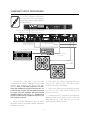
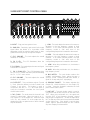
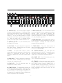
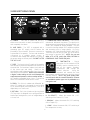
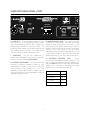
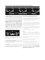
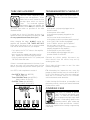
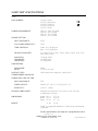
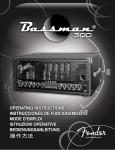
The
sunn
Legacy...
In early 1963, a band from Oregon called “The Kingsmen” hit the charts
with a catchy little tune called Louie Louie. The Kingsmen quickly became
household names and Louie Louie the rock anthem of the decade.
With a hit single under their belt, The Kingsmen soon found
themselves embarking on a 50 state national tour. One of the first
things bassist Norm Sundholm discovered was that his bass amp,
while fine for hops and school dances, did not have the power
necessary for the larger concert halls to which the band had ascended.
To solve this dilemma, Norm enlisted the help of his brother Conrad
and by 1964 the brothers Sundholm had designed the world’s first high
powered concert bass amplifier.
1965 saw the demand for the Sundholms’ amplifiers increase to the point
that the family garage would no longer serve as a suitable manufacturing
facility. Thus, the SUNN Musical Equipment Company was born.
As the years passed, countless pioneers of rock would rely on SUNN
amplifiers to carry the weight.
The Who, Moody Blues, Cream,
Steppenwolf, Kiss, Rush, Queen and a little music festival in up-state New
York all endorsed SUNN equipment.
Today, your new SUNN amplifier embodies this rich tradition and
combines it with a vision for the future that this American institution known
for big sound was built upon.
SUNN® STAGE GEAR... Attitude, Power and Performance for Professionals
SUNN 300T BASS AMPLIFIER
VACUUM TUBE DESIGN IN BOTH THE Congratulations on your purchase of a Sunn® 300T
Bass Amplifier. Built with care and special attention
PREAMP AND POWER AMPLIFIER
to detail, your new Sunn 300T Bass Amplifier offers
much more than meets the eye. Each 300T bass
amplifier is crafted from the finest components
available and assembled at the Sunn amplifier factory
in Corona, California, USA.
CONSTRUCTED IN AN ALL STEEL
CHASSIS FOR ENDURING RELIABILITY
300 WATTS OF POWER
The Sunn® 300T Bass Amplifier includes among its
many features: 300 Watts of power (into 2, 4, or 8Ω);
active compression circuitry and a 10-band graphic
equalizer and high and low frequency controls for fullbodied tonal shaping. The two channels are voiced
for both clean and distortion outputs offering the
versatility of differing playing styles. The footswitch
circuitry allows for remote selection of the front panel
graphic equalizer, compressor and the channel
selection. Moreover, the rear panel features an effects
loop for the addition of external signal processing
devices or outboard gear, an impedance switch for
different speaker cabinet loads, a tuner out jack for
accessing your tuner and both XLR and 1/4 inch line
out jacks and a pass through jack for routing your
bass signal to another amplifier or mixing console.
TWO CHANNELS WITH CLEAN AND
DISTORTION MODES
TRANSFORMER-BALANCED LINE OUT
WITH SPEAKER EMULATION
FOOTSWITCH JACK FOR REMOTE ONOFF SWITCHING OF THE GRAPHIC
EQUALIZER,
COMPRESSOR
AND
CHANNEL SELECTION
LOW-NOISE DIFFERENTIAL EFFECTS
LOOP FOR SIGNAL PROCESSING
In order to thoroughly understand the operation,
DEVICES
features and functions of your new Sunn 300T Bass
Amplifier, please read and refer as needed to this
operation manual. By doing so, your amplifier is sure
to provide you with years of trouble-free music
making and maximum playing enjoyment.
SPLIT BAND COMPRESSOR
Take the time to get to know each other... Tune-up,
Plug-in and ... Play On!
WARNING:
-TO PREVENT DAMAGE, FIRE OR SHOCK
HAZARD, DO NOT EXPOSE THIS UNIT TO RAIN
OR MOISTURE.
-NO USER SERVICEABLE PARTS INSIDE,
REFER SERVICING TO QUALIFIED PERSONNEL
ONLY.
-ALLOW AT LEAST 3 INCHES (7.6 CM) IN THE
FRONT AND REAR OF THE UNIT FOR PROPER
VENTILATION. DO NOT BLOCK VENTS.
-THIS UNIT MUST BE EARTH GROUNDED.
3
SUNN 300T SETUP PROCEDURES
To ensure optimum performance
from your Sunn 300T Bass Amplifier,
please follow these setup guidelines
and procedures.
From Effects Loop Send to
Effects Processor In
From Effects Processor to
Effects Loop Return
effects
loop
power amp
pass through
line out
tuner
out
speaker
impedance
on
off
power
send
return
footswitch
From Power Amp Pass
Through to Effects Loop
Return on another amp
8Ω
4Ω
2Ω
main
speaker
external
speaker
From Line Out to External
Power Amp or Mixer
From Footswitch Out Jack to Footswitch
From Tuner Out to
Tuning Device
From Speaker
Jacks to
Speaker Cabinets
1. Connect your Sunn 410H / Sunn 215 Bass
Loudspeaker Enclosure or equivalent to the parallel
speaker jacks located on the rear of the 300T
amplifier. Note: For improved performance, DO NOT
daisy chain multiple enclosures off the same jack. As
a rule of thumb, connect only one speaker enclosure
per output jack and remember the total minimum
impedance load for the 300T is 2Ω. Remember to
connect or disconnect any speaker enclosure to your
300T with the power off.
3. Next, attach the 3-button footswitch and your
tuner to the TUNER OUT and FOOTSWITCH jacks
located on the rear of the amplifier.
4. Connect any effects processing devices through
the EFFECTS LOOP SEND and RETURN jacks on
the rear of the unit.
5. If sending your 300T’s signal to an external power
amplifier or main house mixer, connect a cord from
either the 1/4 inch or XLR LINE OUT jack to your
external power amplifier or mixer.
2. Set the SPEAKER IMPEDANCE switch to match
the power amp to the proper speaker impedance
load (item M, page 9).
4
6. Make sure the HIGH and LOW tone controls are
in their center notched positions, the Graphic EQ is
“flat”, the compressors are OFF and the LOW, HIGH
and MID NOTCH buttons are out.
13. To use the compression circuitry, simply press
the COMP ON / OFF button located between the
COMP EQ BAL and COMP GAIN TRIM buttons.
14. Be sure to check the signal level led during your
tone setup to ensure you are not overdriving or
clipping the preamp. If the SIGNAL LEVEL LED
flashes red after all tone adjustments have been
made, simply turn down the CH.1 VOLUME until the
distorted sound diminishes.
7. Turn your amplifier ON and then the STANDBY
switch on.
8. Begin playing your Bass as vigorously as you
would during any regular performance; if necessary
engage the -6dB PAD button. In order to obtain the
optimum signal from the preamp, it is important to
play with your maximum performance intensity when
setting up the 300T.
15. If at any time during your performance the 300T
begins to distort without the CH. SELECT switch
engaged, simply turn down the CH.1 VOLUME until
the distorted sound diminishes.
9. Turn the channel 1 volume control up until the
INPUT LEVEL LED flashes red. Next, turn down the
CH. 1 VOLUME level until the LED flashes red
occasionally; this will ensure maximum output
without clipping the preamp.
10. Turn the MASTER VOLUME to your desired
playing level.
11. Next, set your 300T to your desired tone settings
using the compressors and graphic EQ if so desired.
12. To use the graphic eq, simply press the graphic
ON / OFF button located next to the EQ watching for
the LED to illuminate. You may use the EQ TRIM to
match gain levels which may be affected when
switching the graphic equalizer in and out.
5
SUNN 300T FRONT CONTROL PANEL
L
O
N
M
P
post
pre
B
-6dB
pad
high
low
ch
select
mix
graphic
mid
notch
+12dB
OdB
-12dB
gain
volume
volume
mix
low
high
I
J
K
31.5
63
125
250
500
1k
2k
4k
8k
input
A
C
D
E
F
G
H
A. INPUT - Plug your bass guitar in here.
Q
J. LOW - This knob adjusts the amount of increase or
decrease in the low frequency content of both
channels. In its center notched position, the low
frequency control is “flat” with none of the
corresponding frequencies increased or decreased.
B. -6 dB PAD - Sensitivity / gain switch for the input
signal. When this button is in, it provides a 6dB
attenuation useful for reducing input levels on bass
guitars with active pickups or high level outputs.
K. HIGH - This knob adjusts the amount of increase or
decrease in the high frequency content of both
channels. In its center notched position, the high
frequency control is “flat” with none of the
corresponding frequencies increased or decreased.
C. CH 1 VOLUME - This knob adjusts the overall
loudness of channel 1.
D. CH 1 LED - This LED illuminates when the
channel 1 is active.
L. LOW - When this push button is in, it activates a
low frequency boost.
E. CH 2 GAIN - This knob adjusts the amount of gain
or distortion in Channel 2.
M. HIGH - When this push button is in, it activates a
high frequency boost.
F. CH 1 / 2 MIX LED - This LED illuminates when
the CH SELECT button has been pressed indicating
the Ch. 1 / Ch. 2 mix is active.
N. MID NOTCH - This push button reduces the
“muddy” mid-frequency tones, giving the amp a
“punchy” sound. Utilizing the mid notch button, is
good for “thump and pluck” style playing.
G. CH 2 VOLUME - This knob adjusts the overall
loudness of channel 2.
H. CH SELECT - This push button selects Channel
1 / 2 mix. When this button is in, both Channel 1 and
Channel 2 are active. This button is used in
conjunction with the CH. 1 / 2 MIX knob (item I).
Using the footswitch overrides the front panel
channel select switch.
O. GRAPHIC ON/OFF - This button activates the
Graphic EQ. When the button is in, the Graphic EQ
is active. Using the footswitch overrides the front
panel channel select switch.
P. LINE OUT - This push button switch is used in
conjunction with the line out jacks on the rear of the
300T. When this push button is in, the signal sent
from the 300T is post frequency shaping, channel
switching and compression. The line out signal does
NOT include any effects which may have been added
via the effects loop. If the button is out, the bass
guitar’s signal is passed through the 300T without
any tone shaping or enhancement.
I. CH 1 / 2 MIX - This knob mixes the channel 1 and
channel 2 output levels. When the knob is at “1”,
only channel 1 is in the output mix. When the knob
is at “10”, only channel 2 is in the output mix. By
rotating the knob, an optimum mix of both channels
may be obtained.
6
O
N
M
P
post
pre
high
line out
graphic
mid
notch
comp
input
level
comp
on
off
+12dB
power
tuner
only
OdB
5
250
500
1k
2k
4k
8k
16k
eq
trim
-12dB
low
comp
master
volume
comp
gain trim
comp
eq bal
high
comp
standby
Q
R
S
T
U
W
V
Q. GRAPHIC EQ - This 10 band graphic equalizer
consists of active band pass / band reject filters
spaced at octave intervals. Moving the sliders up or
down boosts or cuts the gain at the indicated
frequency. The EQ Trim slider provides an increase
or decrease of the bass’ signal through the graphic
EQ. When the slider is at its centered notched
position, the input signal is neither boosted or cut.
X
Y
Z
AA
BB
CC
X. INPUT LEVEL LED - This LED illuminates GREEN
once the threshold of the compressor has been
reached. When a RED light is displayed, this
indicates clipping and your 300T is being overdriven.
When the compression circuitry is not engaged, the
LED will still indicate signal level.
R. GRAPHIC EQ LED - This LED illuminates when
the Graphic EQ is active.
Y. COMP GAIN TRIM - This knob adds gain to make up
for any level lost once the compression circuitry has
been engaged. Rotating the knob clockwise
increases the amount of gain.
S. LOW COMP - This knob adjusts the compression
ratio below 400Hz. Rotating the knob clockwise
increases the compression ratio.
Z. TUNER ONLY - This push button mutes all
outputs and sends your bass guitar's signal to your
tuning device (not included).
T. COMP - This push button switch is used to
activate the on-board compressors. When this push
button is in, compressors are active. Using the
footswitch overrides the front panel channel select
switch.
AA. MASTER VOLUME - This knob adjusts the
overall volume level of the 300T. Rotating the knob
clockwise increases volume with “1” producing no
volume and “10” producing maximum volume.
BB. POWER LED - This LED illuminates when the
300T is ON and receiving power.
U. HIGH COMP - This knob adjusts the compression
ratio above 400Hz. Rotating the knob clockwise
increases the compression ratio.
CC. STANDBY - When the power switch and this
switch are ON, your Model T is ready to perform. In
the STANDBY position, power is supplied ONLY to
the tube filaments and sound will NOT come out of
the amp. Using the STANDBY SWITCH during short
breaks eliminates tube warm-up time and will
increase tube life.
V. COMP LED - This LED illuminates when the
compression circuitry is active.
W. COMP EQ BAL - This detented knob mixes the
low and high compressor outputs. When the knob is
at “1”, only the low compressor is in the output mix.
When the knob is at “10”, the high compressor is in
the output mix. By rotating the knob, an optimum mix
of both compressors can be obtained.
7
SUNN 300T REAR PANEL
effects
loop
on
A
B
power amp
pass through
D
C
E
F
off
send
power
return
F. POWER AMP PASS THROUGH - This 1/4 inch,
unbalanced, differential, tip-sleeve (TS) output jack is
designed to send a preamp line level signal from your
“Main” 300T amplifier to another amplifier. This jack
is used for chaining multiple 300T amplifiers together
and increasing your on stage volume. Do so by
inserting a 1/4” cable from this POWER AMP PASS
THROUGH jack into the RETURN jack in the effects
loop section of another 300T. NOTE: You can use
either a TS or TRS cord in the SEND, RETURN or
POWER AMP PASS THROUGH jacks.
A. POWER - Turns the AC power ON and OFF.
When the rocker switch is down, the amplifier is OFF
and completely shut down.
B. LINE CORD - The 300T is equipped with a
grounding type IEC supply cord to reduce the
possibility of shock hazard. Be sure to connect it to
a grounded AC receptacle. The line cord should be
connected to a suitable power source in
accordance with voltage and frequency as shown in
the power rating on the rear panel. DO NOT ALTER
THE AC PLUG.
G. FOOTSWITCH - Plug-in
connection for the footswitch (P/N
053895) used to remotely turn on
and off the graphic equalizer,
compressors and change the
Using the
footswitch channel selection.
footswitch will override the front
panel graphic equalizer, compressor and the channel
selection buttons. NOTE: Any good quality patch
cord will work with the remote footswitch, however
an unshielded speaker type cord is preferable to a
coax guitar cord.
G
C. FUSE - The fuse is in the AC supply of the amplifier
and will help to protect the amplifier in the event of an
electrical fault. If a fuse blows, replace it only with one
of the same type and rating.
(Refer to the
specification page to determine the correct fuse type
and rating for your amplifier). NEVER use a fuse with
a higher current rating as this could damage the
equipment and present a serious safety hazard. If
the amplifier repeatedly blows fuses, it should be
taken to an authorized Fender service center.
D. SEND - This 1/4 inch, unbalanced, differential, tipsleeve (TS) output jack is designed to send a signal
to an external signal processing device, such as a
digital delay or a chorus unit.
H
E. RETURN - This 1/4 inch, balanced, tip-ring-sleeve
(TRS) input jack is designed to accept signal from an
external processing device, such as a digital delay or
a chorus unit.
I
J
H. CH SELECT - Allows the remote ON / OFF
switching of the Channel 1 / 2 mix.
I. GRAPHIC - Allows the remote ON / OFF switching
of the Graphic EQ.
J. COMP - Allows the remote ON / OFF switching of
the compression circuitry.
8
SUNN 300T REAR PANEL, CONT.
line out
K
tuner
out
L
M
speaker
impedance
8Ω
4Ω
2Ω
N
O
main
speaker
external
speaker
N. MAIN SPEAKER JACK - This is the main plug-in
connection for your speaker enclosure and should
always be used as the primary connection. If your
300T’s power and standby switches are in their on
positions, make sure a load of at least 2Ω is present.
Failure to do so may result in your 300T being
damaged by using an improper impedance load. As
a rule of thumb, ALWAYS connect or disconnect any
speaker enclosure to your 300T with the power off.
K. LINE OUT - These transformer balanced, XLR
male and 1/4 inch, tip-ring-sleeve, line level output
jacks are designed to feed the 300T’s signal to an
external power amplifier or main house mixer. The
signal from these output jacks include all effects and
tone shaping done by the 300T. The output of this
jack also includes a speaker emulation circuit.
L. TUNER OUT - This 1/4 inch, unbalanced, TS
output jack is designed to send your bass guitar's
signal to your tuning device (not included).
O. EXTERNAL SPEAKER JACK - Plug-in
connection for an additional speaker enclosure. This
jack is wired in parallel with the main speaker jack
and must ONLY be used in conjunction with the main
speaker jack. If this jack is used without the main
speaker jack, no sound will be produced.
M. SPEAKER IMPEDANCE - This switch allows the
selection of different impedance loads for your
loudspeaker enclosure(s). Make sure to match the
total speaker’s load impedance to the load
impedance selector switch setting. Failure to do so
may result in your 300T being damaged by using an
improper impedance load.
Speaker Cabinets
9
LoadΩ
1 8Ω Cabinet
8Ω
2 8Ω Cabinets
4Ω
1 4Ω Cabinet
4Ω
2 4Ω Cabinets
2Ω
300T OUTPUT TUBE BIAS INDICATORS AND CONTROLS
6550C
P
6550C
6550C
P
replace with
T100mA fuse only
6550C
6550C
6550 C
P
replace with
T100mA fuse only
P. TUBE TROUBLE - This LED indicates tube failure
or trouble at the tube’s respective location. When the
LED glows green, the tubes are operating properly.
When the LED glows red, this indicates a tube failure
which has blown the fuse at the respective fuse
location on the top surface of the chassis. NOTE: It is
normal for the LEDs to glow RED when the amp is in
STANDBY mode. If a fuse blows, replace it only with
one of the same type and rating. NEVER use a fuse
with a higher current rating as this could damage
the equipment and present a serious safety
hazard. Next, replace the tubes in their respective
locations, check and adjust the bias and balance. If
the amplifier repeatedly blows fuses, it should be taken
to an authorized Fender service center.
Output Tube Bias Adjustment Instructions
1. Turn on your 300T and let it warm up for at least two
minutes with the STANDBY switch in the ON position. Make
sure the amplifier is properly connected to a speaker.
2. Remove the bias controls cover box.
3. With a digital voltmeter set to its most sensitive DC
voltage scale, measure the voltage between the BIAS
100mV test points (test points 1&2) and adjust the BIAS
control for a reading of .1 VDC (100 mVDC).
4. Next, connect the digital voltmeter to the BALANCE 0V
test points (test points 2&3) and adjust the BALANCE control
for a reading of 0 VDC.
5. Replace the bias controls cover box.
Q
1
R
3
2
Notes
1. Make bias and balance adjustments ONLY when
necessary. If you are unsure about setting bias and
balance, take your amp to the nearest authorized Fender
Service Center.
S
h
Q. BIAS - This trim adjustment is used in conjunction
with the BALANCE and the bias test points to set the
output tube bias.
2. For optimum sonic performance, set bias to 100mVDC
then set balance.
3. If the output tubes can not be biased to at least
80mVDC, replace the 6550C output tubes.
R. BIAS 100mV & BALANCE 0V - These are bias
test points used to measure output tube bias and
balance with a digital voltmeter.
4. If the output tubes can not be balanced, check the bias
setting and/or replace the 6550C output tubes.
5. The power tube trouble LEDs are NOT indicators of worn
tubes. If your tubes are worn and sound weak the LEDs
may still glow green. The trouble LEDs turn RED only after
tube failure has already occurred. DO NOT WAIT FOR
TUBE FAILURE TO REPLACE TUBES.
(See Tube
Replacement Section, page 11).
S. BALANCE - This trim adjustment is used in
conjunction with the bias test points and the BIAS
adjustment to set the bias balance between the
power amp tube sections of your 300T.
10
TUBE REPLACEMENT
TROUBLESHOOTER’S CHECKLIST
Tube life varies depending upon
playing style and application. Power
tubes have a much shorter life than
pre-amp tubes which can last for
years.
For continued optimum
performance from your amplifier, the
tubes should ONLY be replaced with
the same type tubes as specified on the tube
illustration below.
If the amp is set up but does not
function, check the following items:
• Is the power cord properly plugged into an
electrical outlet?
• Is there power at the outlet?
• Is the instrument properly plugged into the
amplifier?
• Are the control knobs turned above 1?
• Is the volume control on your bass guitar turned up?
• Is the TUNER ONLY button disengaged?
• Is the STANDBY switch in the ON position?
• Are any cords cut or frayed?
• If using the effects loop, is the effects unit(s) is
properly plugged into the amplifier?
• Is there power to your effects unit(s)?
• Is the amplifier properly plugged into your
speaker cabinet or enclosure?
A simple way to check if the tubes are worn is to
replace the set in your amp with your spare set. (You
do carry spare tubes and fuses, don't you?)
When changing the tubes, ALWAYS unplug the
amplifier and remember THE TUBES ARE HOT!
Either wait for the tubes to cool or use an insulated
oven mitt to remove them from your amplifier.
• First, replace the OUTPUT tubes in the amplifier,
re-bias and listen.
• Next, re-insert the original output tubes and rebias. Replace the PRE-AMP tubes and listen.
• Finally, try replacing both the OUTPUT (re-bias) and
PRE-AMP tubes and listen.
Eliminate any effects pedals, disconnect any
effect devices from the effects loop and try
another guitar cord.
If there is a marked improvement in the tone of your
amp at any point in this procedure, leave the new
tubes in your amp and purchase another spare set.
Check under all tube covers to see if the tube
filaments are glowing.
Your 300T's tube compliment consists of:
FYI: Attenuating low frequencies may cause the
preamp to distort and this may not cause the INPUT
LEVEL LED to flash red. if this is the case, simply turn
down the CH.1 VOLUME and / or CH.2 VOLUME
until the distorted sound diminishes.
• One 12AT7A Tube (part #023531),
(tube location V4)
• Three 12AX7WA Tubes (part #013341)
(tube locations V1 thru V3).
• Six 6550C Tubes (part #048489),
(tube locations V5 thru V10).
If, after checking all of the above, your amplifier is not
performing correctly, consult your nearest authorized
Fender service center.
COVERING CARE
Your 300T is covered in genuine
Tolex® for long life and lasting good
looks. To clean the Tolex covering,
use a sponge and a light soapy water
solution. Avoid spilling liquids on the
operating surfaces, grille, volume and
tone controls and switches. ALWAYS
unplug your amplifier before cleaning or approaching
it with fluids.
11
SUNN® 300T SPECIFICATIONS
TYPE:
PR 347
PART NUMBER:
21-3302
21-3332
21-3342
21-3362
21-3372
(120V)
(240V) Aust
(230V) UK
(230V) Eur
(100V)
POWER REQUIREMENTS:
100V
120V
230V
240V
50/60 Hz 900W
60 Hz, 900W
50 Hz, 900W
50 Hz, 900W
AC,
AC,
AC,
AC,
PREAMP SECTION
INPUT IMPEDANCE:
470kΩ
FULL POWER SENSITIVITY :
12mV
TONE CONTROLS:
Treble: +/-15 dB @ 6kHz
Bass: +/-15 dB @ 40Hz
GRAPHIC EQUALIZER:
+/-12 dB @ 31.5Hz, 63Hz, 125Hz, 250Hz, 500Hz, 1kHz, 2kHz,
4kHz, 8kHz, 16kHz.
MID NOTCH:
LOW BOOST:
HIGH BOOST:
-20 dB @ 700Hz
+10 dB @ 40Hz
+10 dB @ 6kHz
COMPRESSOR
CROSSOVER:
RATIO:
LINE OUT LEVEL:
(TRANSFORMER BALANCED)
400Hz
1:1 Min to 4:1 Max
+6dB referenced to input (pre), 0dBV (post).
POWER AMPLIFIER SECTION
INPUT IMPEDANCE:
20kΩ
POWER OUTPUT:
300W R.M.S. into 2, 4, or 8Ω @ <3% T.H.D.
SENSITIVITY :
1V R.M.S. (0dBv)
SPEAKER COMPLIMENT:
Designed for use with the Sunn 410H or Sunn 215 Bass
Loudspeaker Enclosures
DIMENSIONS:
Height: 10.1 in
Width: 25.5 in
Depth: 15.6 in
WEIGHT:
75 lbs
25.7 cm
64.8 cm
40 cm
34 kg
SUNN® is a registered trademark of Fender Musical Instruments
Corporation.
Product specifications are subject to change without notice.
A PRODUCT OF:
FENDER MUSICAL INSTRUMENTS CORP.
CORONA, CA 91720 USA
P/N 053937
REV A