1
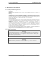
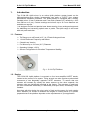
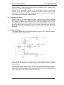
T e c h n i c a l
D o c u m e n t a t i o n
User Manual PZ 125E
S-334
Tip/Tilt Mirror
Release 1.10
Product Description
and
Operating Notes
This Document is valid for the following Products:
S-334.2SL
Piezo Tip/Tilt Mirror, ±25 mrad, Closed-Loop
Release:
Release Date:
1.10
2003-06-05
© Physik Instrumente() GmbH & Co. KG
76228 Karlsruhe, Germany
FAX: (+49)721-4846-299
E-Mail: [email protected]
Internet: www.pi.ws
S-334 XY Tip/Tilt Mirror
User Manual PZ 125E
Table of Contents :
0.
Manufacturer Declarations ................................................................. 2
0.1. Quality and Warranty Clauses................................................................. 2
0.2. Safety Precautions .................................................................................. 2
1.
Introduction.......................................................................................... 3
1.1. Features .................................................................................................. 3
1.2. Design ..................................................................................................... 3
2.
Quick Start ........................................................................................... 4
3.
Working Principle ................................................................................ 4
3.1. Position Sensors...................................................................................... 4
3.2. Operating Voltages.................................................................................. 5
3.3. Motion Polarities ...................................................................................... 5
4.
Drive Electronics ................................................................................. 6
5.
Dynamic Behavior ............................................................................... 7
6.
S-334.2SL Technical Data ................................................................... 8
6.1. Specifications .......................................................................................... 8
6.2. Connectors .............................................................................................. 8
6.3. Dimensions.............................................................................................. 9
© Copyright 2003 by Physik Instrumente (PI) GmbH & Co. KG
Release: 1.10
File:S-334UserPZ125E110.doc, 145920 Bytes
Release 1.10
www.pi.ws
Page 1
S-334 XY Tip/Tilt Mirror
User Manual PZ 125E
0. Manufacturer Declarations
0.1. Quality and Warranty Clauses
Certification
Physik Instrumente (PI) certifies that this product met its published specifications at the time of
shipment.
Warranty
This PI product is warranted against defects in materials and workmanship for a period of one year
from date of shipment. Duration and conditions of warranty for this product may be superseded when
the product is integrated into (becomes a part of) other PI products. During the warranty period, PI
will, at its option, either repair or replace products which prove to be defective.
Limitation of Warranty
The foregoing warranty shall not apply to defects resulting from improper or inadequate maintenance
by the Buyer, Buyer supplied products or interfacing, unauthorised modification or misuse, operation
outside of the environmental specifications for the product, or improper site preparation or
maintenance.
The design and connection of any circuitry to this product is the sole responsibility of the Buyer. PI
does not warrant the Buyer's circuitry or malfunctions of PI products that result from the Buyer's
circuitry. In addition, PI does not warrant any damage that occurs as a result of the Buyer's circuit or
any defects that result from Buyer-supplied products.
No other warranty is expressed or implied. Physik Instrumente specifically disclaims the
implied warranties of merchantability and fitness for a particular purpose.
0.2. Safety Precautions
Warning
To avoid irreparable damage, S-334 Tip/Tilt Mirrors should never be operated in
open-loop (servo OFF) mode or be subjected to frequencies above 200 Hz (300
Hz for small-signal frequencies).
Warning
Handle the factory installed mirror with care. Never try to remove the mirror.
Release 1.10
www.pi.ws
Page 2
S-334 XY Tip/Tilt Mirror
1.
User Manual PZ 125E
Introduction
The S-334.2SL tip/tilt mirror is an active tip/tilt platform system based on the
differential-piezo-drive design incorporating two pairs of LVPZT (low voltage
piezoelectric translator) actuators. The tip/tilt platform is equipped with a factory
installed mirror 10 mm in diameter and 2 mm thick (flatness λ/5, reflectivity > 98%
from 500 nm to 2 µm). Custom coatings and mirrors up to 12.5 mm diameter are
available on request.
It is designed for fast and precise laser beam steering in two orthogonal axes and
for stabilizing and correcting optical axes or paths. The tip/tilt range is ±25 mrad
with sub-µrad resolution.
1.1. Features
¾ Tilt Range up to ±25 mrad (±1.5°) in 2 Fixed Orthogonal Axes
¾ 1.0 kHz Resonant Frequency with Mirror
¾ Closed-Loop Version
¾ For Mirrors up to 12.5 mm (0.5 ”) Diameter
¾ Operating Voltage ≤100 V
¾ Sensor Configuration for Excellent Temperature Stability
Fig. 1. S-334 Tip/Tilt Mirror
1.2. Design
The S-334.2SL tip/tilt platform is mounted on four lever-amplified LVPZT stacks,
located at the corners of a square. Tilting around one axis requires synchronized
movement of two diagonally opposite LVPZT actuators. To ensure that one
actuator will contract by exactly the same amount as the other expands, the
actuator pairs are individually matched at the factory. The actuators in each pair
are then connected electrically in differential push-pull mode, eliminating Z-axis
freedom.
Note that with this design the pivot point is fixed and the same for both rotation
axes. Whether you choose to measure the angles in vertical planes or in planes
perpendicular to the platform depends on the requirements of your application.
Release 1.10
www.pi.ws
Page 3
S-334 XY Tip/Tilt Mirror
User Manual PZ 125E
2. Quick Start
The following instructions describe starting the S-334.2SL tip/tilt platform using PI’s
E-500-series control electronics (E-500 or E-501 chassis including E-503.00S
amplifier module and E-509.S3 servo-control module). If you use other modules
from the E-500 series the steps are the same, but the connections details may
differ. In this case please consult “Drive Electronics” Section on p. 6 for further
information.
1. Make sure that the control electronics is set up to start in closed-loop mode
(with the mirror not connected).
See the E-500 and the E-509 User Manuals for details. If you have an E-516.i3
interface module installed, please see also the User Manual for that unit. If necessary
switch on the control electronics using the power switch on the rear of the chassis
without the tip/tilt mirror connected, verify that servo is ON and then switch it off again.
2. Connect the S-334.2SL tip/tilt mirror to the E-509.S3 servo-control module.
The sensor cables of the S-334, which are labeled “AXIS 1” and “AXIS 2”, must be
plugged into the corresponding sockets of the servo-control module (labeled “SERVO
1” and “SERVO 2”).
3. Connect the S-334.2SL tip/tilt mirror to the E-503.00S amplifier module.
The supply voltage cables of the S-334.2SL are labeled “PZT CH1”, “PZT CH2” and
“PZT 100V”. They must be plugged into the corresponding output sockets of the
amplifier module.
Note: Do not mix up the cables while connecting, since the amplifier channels are
connected internally so as to supply mirror channels 1 and 2 with variable drive signals,
while its third PZT channel is supplied with a constant and very stable voltage of +100
volts.
Warning: Resonance Can Cause Permanent Damage
The system must never be operated close to the resonant frequency or
permanent damage can result. Keep large-signal values below 200 Hz and
small-signal values below 300 Hz. If you hear or see resonant behavior, switch
off the unit immediately.
Never operate with servo-control OFF (open-loop) or with the sensors
disconnected.
4. Switch on the control electronics.
Consult the E-500 User Manual, and, if you have an E-516 interface module installed,
the E-516 E-User Manual for information on commanding the S-334 tip/tilt platform.
3. Working Principle
The PZT actuators of the S-334 tip/tilt platform in each pair are connected in
differential push-pull mode: any change in the operating voltage causes one
actuator of the pair to see a voltage increase, the other to see a decrease of the
exact same magnitude.
3.1. Position Sensors
As a closed-loop system, the S-334.2SL is equipped with two pairs of strain gauge
position feedback sensors operated in a bridge circuit for ultra-high resolution and
Release 1.10
www.pi.ws
Page 4
S-334 XY Tip/Tilt Mirror
User Manual PZ 125E
angular stability. These sensors permit angular movements to be executed with
sub-µrad resolution and repeatability.
Because of the symmetrical design of the tip/tilt platform system, temperature
changes will not effect the angular orientation but only the Z-axis position (axial
thermal drift). Most applications are much less sensitive to this kind of instability as
long as the angular orientation remains stable.
3.2. Operating Voltages
Each tilt axis of the tip/tilt platform system requires one controlled operating
voltage in the range of 0 to +100 volts and one constant voltage of +100 V. At the
zero position (tilt angle zero) both actuators of a pair are expanded to 50% of their
maximum expansion. Control voltages below 50 volts cause tilting in one direction,
above 50 volts, tilting in the other. A 0 to 10 V control input thus covers the full tilt
range. Operation over an extended range of -20 to +120 V is possible with certain
limitations.
3.3. Motion Polarities
The diagram below shows the relative positions of the four PZT stacks and makes
the relative rotation polarities clear.
Fig. 2. S-334 viewed from above with axis 2 running left and right. PZT stacks
connected to the fixed 100 V supply contract with increasing input, grounded
stacks expand.
In other words, after a positive axis-1 tilt (CH 1), looking uphill across the platform,
a subsequent positive axis-2 (CH 2) tilt would go up to the left and down to the
right. Conversely, facing uphill after a positive axis-2 (ch. 2) tilt, a positive axis-1
(ch. 1) tilt would go down to the left and up to the right.
Release 1.10
www.pi.ws
Page 5
S-334 XY Tip/Tilt Mirror
4.
User Manual PZ 125E
Drive Electronics
The S-334 tip/tilt platform can be controlled by electronics of the E-500 series.
Amplifier and servo-control modules are always required, other modules are
required as noted below:
Amplifier (choice of the following, always required):
E-503.00S
Amplifier module special connected for differential-drive
LVPZT tip/tilt platforms; 2 channels with variable drive signals
(output sockets “CH1” and “CH2”) plus 100 V fixed output
(output socket “CH3”)
E-505.00
Single Channel amplifier module, 3 modules required, “PZT
CH1” must be connected to the leftmost module, “PZT CH2” to
the center module and “PZT 100V” to the rightmost E-505
Note: On amplifiers for tip/tilt mirrors, the DC-offset potentiometer for channel 3, if
present at all, is disabled and the output is clamped internally to +100 volts. The
analog input of this channel is also disabled. External control voltages thus must
be supplied to the CONTROL INPUT sockets of CH1 and CH2.
Controller (always required):
E-509.S3
Position servo-control module for SGS sensors; channel 1 and
2 (labeled “SERVO 1” and “SERVO 2”) shall be used with the
appropriate sensor cables, third channel (input socket
“SERVO 3”) is not used.
Display Module (displays position or voltage of axes, not required):
E-515.03
3½-digit LED position or voltage display for each of 3 channels
(channel 3 not used)
E-515.01
3½-digit LED position or voltage display, 1 channel (2 modules
needed for 2-axis display)
Computer Interface and Display Module (replaces display above, required for
computer-controlled operation):
E-516.i3*
Computer Interface and Display Module, 3 channels, (channel
3 not used)
*The discontinued E-515.i3 can also be used.
Release 1.10
www.pi.ws
Page 6
S-334 XY Tip/Tilt Mirror
5.
User Manual PZ 125E
Dynamic Behavior
In addition to the amplifier, servo controller and sensor bandwidths, the maximum
operating frequency of a tilt mirror depends on its mechanical resonant frequency.
See “S-334.2SL Technical Data” on p. 8 for the resonant frequency of the tip/tilt
platform equipped with the factory installed standard mirror (10 mm in diameter
and 2 mm thick).
Warning
The system must never be operated close to the resonant frequency since permanent
damage can result. Keep large-signal values below 200 Hz and small-signal values
below 300 Hz. Never operate with servo-control OFF (open-loop) or with the sensors
disconnected.
Increasing the effective mass of the loaded platform reduces the resonant
frequency of the system. If you use the S-334 tip/tilt platform with a custom mirror,
call your local PI representative for the resulting resonant frequency.
Release 1.10
www.pi.ws
Page 7
S-334 XY Tip/Tilt Mirror
User Manual PZ 125E
6. S-334.2SL Technical Data
6.1. Specifications
Models
Active axes
Design
Tip/tilt range 0 to 100 V1
Closed-loop tilt angle ≥
Integrated feedback sensor
Open-loop / closed-loop resolution2 ≤
Closed-loop linearity (typ.)
Electrical capacitance3
Dynamic operating current coefficient (DOCC) 4
Resonant frequency w/ Ø 10 x 2 mm glass mirror5
Distance, pivot point to platform surface
Operating temperature range6
Voltage connection
Sensor connection
Weight (w/o cables)
Material
S-334.2SL
Units
2 fixed orthogonal tilt axes
Differential-piezo drive (4
LVPZT stacks)
±25
mrad ±20%
±25
mrad
2 x strain gauge full bridge
5
µrad
± 0,25
%
3.6 / axis
µF ±20%
0.22 / axis
µA/(Hz x µrad)
1
kHz ±20%
approx. 2
mm
0 to 60
°C
3 x Lemo fem. 2 m cable
2 x Lemo, 2 m cable
65
g ±5%
Titanium
Notes:
1
Range: Operation over a -20 to +120 V range is possible if excursions to the limits are of short
duration. See “Lifetime of PZTs” in the PI Catalog for more information. Special open-loop
version with ± 2.5 mrad for 0-100 V is available on request.
2
Resolution of PZT tip/tilt platforms is not limited by friction or stiction. Value is typical (RMS,
1σ) noise-equivalent motion with E-503 amplifier module.
3
Full-Range Repeatability: Typical values, closed-loop mode. Since repeatability is a
percentage of angle traveled, repeatability is significantly better for small ranges.
4
Dynamic Operating Current Coefficient in µA per hertz and µrad. Example: Sinusoidal scan of
100 µrad at 10 Hz requires approximately 0.22 mA drive current.
5
Resonant Frequency with Mirror: This value is valid for the tip/tilt stage with factory installed
standard mirror (10 mm in diameter and 2 mm thick). If you use a custom mirror (with up to
12.5 mm diameter), call your local PI representative for the resulting resonant frequency.
6
Standard range, other temperature ranges on request. Closed-loop systems are calibrated for
optimum performance at room temperature. Recalibration is recommended if operation is at a
significantly higher or lower temperature.
6.2. Connectors
The S-334 tip/tilt platform is equipped with cables for supply voltage and sensor
signals and LEMO connectors to match the amplifier and servo controller modules.
The supply voltage cables of the S-334.2SL are labeled “PZT CH1”, “PZT CH2”
and “PZT 100V”.
The sensor cables of the S-334.2SL are labeled “AXIS 1” and “AXIS 2”.
Release 1.10
www.pi.ws
Page 8
S-334 XY Tip/Tilt Mirror
User Manual PZ 125E
6.3. Dimensions
Fig. 3. S-334.2SL shown without mirror; dimensions in mm, decimal places separated by a
commas in drawings
Release 1.10
www.pi.ws
Page 9