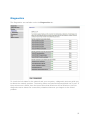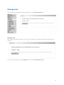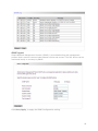
1
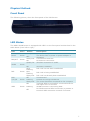
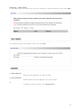
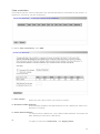
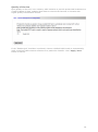
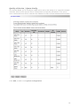
Innoband 8520-B1 User Manual Version 1.0 User Manual Innoband 8520-B1 Information in this document is subject to change without notice and does not represent a commitment on the part of Innoband Technologies, Inc. The software described in this document is furnished under a license agreement and may be used or copied only in accordance with the terms of the license agreement. It is against the law to copy the software on any other medium except as specifically allowed in the license agreement. The licensee may make one copy of the software for backup purposes. No part of this manual may be reproduced or transmitted in any form or by any means, electronic or mechanical, including photocopying and recording, for any purpose without the written permission of Innoband Technologies, Inc. All contents are Copyright © 2012 Innoband, Inc. All rights reserved. Manual Version 1.0 June 2012 Innoband is a trademark of Innoband Technologies, Inc. The trademarks, logos and service marks (“Marks”) displayed on this manual are the property of Innoband or other third parties. Users are not permitted to use these Marks without the prior written consent of Innoband or such third party that may own the Mark. IBM is a registered trademark of International Business Machines Corporation. Intel and Pentium are registered trademarks of Intel Corporation. Microsoft, MS-DOS, Windows, and the Windows logo are registered trademarks of Microsoft Corporation. All other products are trademarks or registered trademarks of their respective owners. Version 1.0 Table Content Getting started ...................................................................................................... 5 Unpacking.......................................................................................................... 5 Choosing right place for your Device ..................................................................... 5 Subscription of Internet Service ............................................................................ 6 Overview ........................................................................................................... 6 Physical Outlook ................................................................................................. 7 Front Panel ........................................................................................................ 7 LED Status ......................................................................................................... 7 Rear Panel ......................................................................................................... 8 System Requirement ........................................................................................... 8 Install your new device .......................................................................................... 9 Connect your Router ........................................................................................... 9 Configure the PC (TCP/IP settings) Introduction.....................................................10 Configure the PC (TCP/IP settings) for Windows 2000 ............................................10 Configure the PC (TCP/IP settings) for Windows XP ................................................11 Configure the PC (TCP/IP settings) for Windows Vista.............................................12 Configure the PC (TCP/IP settings) for Windows 7 ..................................................13 Configure the PC (TCP/IP settings) for Mac OS 9.x .................................................14 Configure the PC (TCP/IP settings) for Mac OS X ...................................................14 Web configuration ................................................................................................16 Router access ....................................................................................................16 Quick start ........................................................................................................16 Access to the Router advanced configuration .........................................................18 Info .................................................................................................................19 Device Info ....................................................................................................19 WAN..............................................................................................................20 Traffic Statistics ..............................................................................................20 Route ............................................................................................................20 ARP Table ......................................................................................................21 Advanced Configuration ......................................................................................22 Connection Mode ............................................................................................22 WAN Service ..................................................................................................23 LAN ...............................................................................................................24 DHCP Settings / Server....................................................................................24 DHCP Settings / Client .....................................................................................26 NAT / Virtual Server ........................................................................................26 NAT / Port Triggering.......................................................................................28 NAT / DMZ Host ..............................................................................................29 Security / IP Filtering Outgoing .........................................................................30 Security / IP Filtering Incoming ........................................................................31 Security / URL Filter ........................................................................................32 Time restriction ..............................................................................................33 Quality of Service............................................................................................34 Quality of Service / Queue Config .....................................................................35 Routing / Default Gateway ...............................................................................36 Routing / Static Route .....................................................................................37 DNS / DNS Server ...........................................................................................38 Dynamic DNS .................................................................................................39 DSL ...............................................................................................................41 UPnP .............................................................................................................41 Interface Grouping ..........................................................................................42 Multicast / IGMP Configuration..........................................................................44 Wireless ...........................................................................................................45 Basic .............................................................................................................45 Security .........................................................................................................46 MAC Filter ......................................................................................................49 Wireless Bridge ...............................................................................................50 Station Info ....................................................................................................50 Diagnostics .......................................................................................................52 Management .....................................................................................................53 System Log ....................................................................................................53 SNMP Agent ...................................................................................................54 TR-069 Client .................................................................................................55 Internet Time .................................................................................................56 Access Control / Passwords ..............................................................................57 Backup ..........................................................................................................58 Update Software .............................................................................................59 Reboot ..........................................................................................................60 Exit ..................................................................................................................61 Back to Wizard ..................................................................................................61 Troubleshooting ...................................................................................................62 Problems with LAN access ...................................................................................62 Problems with WAN access ..................................................................................62 Product specification .............................................................................................63 Product specification ..........................................................................................63 Safety Notes .....................................................................................................64 For Installation ...............................................................................................64 For Using .......................................................................................................64 For Service.....................................................................................................64 Warning .........................................................................................................64 Caution..........................................................................................................65 Glossary ..............................................................................................................66 Certifications........................................................................................................73 FCC..................................................................................................................73 Warranty .............................................................................................................75 Contact information ..............................................................................................77 Getting started Unpacking Check the contents of the package against the pack contents checklist below. If any of the items is missing, then contact the dealer from whom the equipment was purchased. Device Power Adapter and Cord RJ-11 DSL Line Cable (Grey) RJ-45 Ethernet Cable (Yellow) Quick Start Guide CD Verify that the following items came with your INNOBAND 8520-B1 kit: INNOBAND 8520-B1 CD-ROM Quick Start Guide ADSL cable (gray) Ethernet cable (yellow) Power supply Choosing right place for your Device 1. Place the Device close to the wall outlet and power outlet for the cable to reach it easily. 2. Avoid placing the device in places where people may walk on the cables. Also keep it away from direct sunlight or heat sources. 3. Place the device on a flat and stable stand. 4. Connect Cables and Splitter as described below to avoid interferences with your regular telephone service. 5 Subscription of Internet Service To use this Device, you have to subscribe for a service from your broadband service provider. According to the service type you subscribe, you will get various IP addresses: Dynamic IP: If you Apply for dial-up connection, you will be given an Internet account with username and password. You will get a dynamic IP by dialling up to your ISP. Static IP address: If you Apply for full-time connectivity, you may get either one static IP address or a range of IP addresses from your ISP. The number of IP addresses varies according to different service provider. Overview Thank you for choosing the Innoband 8520-B1. The Router lets you access the Internet via a wireless connection or through one of its four switched ports. You can also use the Router to share resources such as computers, printers and files. A variety of security features help to protect your data and your privacy while online. Configuring the Router is easy using the provided browser-based utility. This chapter provides you the description for the LED and connector for front and rear view of the router. Before you use/install this router, please take a look at this information first. 6 Physical Outlook Front Panel The following picture, show the front panel of the DSL Router: LED Status The ADSL WLAN Router is equipped with LED’s on the front panel as described in the table below (from left to right): LED Color Power Green PPP/ACT Green WLAN Green Status Always On DSL LAN 1/2/3/4 Green Green OFF Always On Off Steady On Flashing Off Slow Flashing Fast Flashing Always On Off Flashing Always On ON WPS Green Flashing Off Description The device has power The device has no power or power adapter is damaged Connected to Internet No Internet Connection Wireless connection is made Packets are being transferred Wireless is disabled DSL Link has not been established DSL Link is being established DSL Link has already been established Unconnected Packets are being transferred The router has been connected to the computer Terminal WPS is successfully connected and the LED lights off in 5 minutes WLAN terminal is connecting WPS No WLAN terminal WPS connection is present or terminal WPS connection exceeds 5 minutes 7 Rear Panel The ADSL WLAN Router is equipped with Connectors/Switches on the rear panel as shown in the picture below: 6 1 2 3 4 5 6 The ADSL WLAN Router is equipped with Connectors on the rear panel as described in the table below (from left to right): 1 2 3 4 5 6 Connector DSL Ethernet 1-4 Power WPS Reset Switch Antenna Desription RJ-11 connector for DSL Ethernet RJ-45 connector (LAN 1-4) 9VAC Power connector Hold and press it for 1 seconds to connect WPS Hold and press it 7 seconds to reset to factory defaults. Power switch Two Antenna connectors System Requirement To access the ADSL Router via Ethernet, the host computer must meet the following requirements: With Ethernet network interface Must have TCP/IP installed Set client PC with obtain an IP address automatically or set fix IP address With a web browser installed: (for example: Internet Explorer, FireFox, Opera, Chrome, etc). The ADSL Router is configured with the default IP address of 192.168.1.1 and subnet mask of 255.255.255.0. As the DHCP server is Enable by default, The DHCP clients should be able to access the ADSL Router. Or you could assign an IP address to the host PC first for initial configuration. You also can manage the ADSL Router through a web browser-based manager: ADSL ROUTER CONTROL PANEL. The ADSL Router manager uses the HTTP protocol via a web browser to allow you to set up and manage the device. 8 Install your new device Connect your Router This chapter is to help you accessing into Internet with a quick and convenient way. If you need more detailed information for web configuration, please get into the next chapter for the advanced configuration. NOTE: To configure the device via web browser, at least one properly-configured PC must be connected to the network (either connected directly or through an external hub/switch to the LAN port of the device). 1. With your computer off, plug the end of the ADSL cable (gray) into the DSL port of your ADSL WLAN Router. 2. Connect the Ethernet cable (yellow) to the LAN port of your ADSL WLAN Router. 3. Connect the other end of the Ethernet cable to the LAN port of your computer. 4. Connect the power supply to your ADSL WLAN Router 5. Plug the power plug into a power outlet. 6. Turn your computer on and wait until your operating system (OS) is started up. 7. Proceed with installation (Read first the introduction and continue then with the paragraph related to your operating system). 6 1 2 4 5 3 9 Configure the PC (TCP/IP settings) Introduction You will learn how to configure your computer to communicate with the Innoband ADSL Router. To do this, you will need to configure your PC’s network settings to obtain an IP address automatically. Computers use IP addresses to communicate with each other across a network or the Internet. Find out which operating system your computer is running, such as Windows 98, Windows ME, Windows NT4, Windows 2000, Windows XP, Windows Vista, Windows 7 or Macintosh OS 9.x, 10.x. You will need to know which operating system your computer is running. You can find out by clicking on Start -> Settings. (If your Start menu doesn’t have a Settings option, you are running Windows XP or Windows Vista. In this case you can select the Control Panel directly from the Start menu.) Then, click on Control Panel and double-click on the System icon. Click the Cancel button when done. Once you know which operating system you are running, follow the directions in this step for your computer’s operating system. The next few pages tell you, step by step, how to configure your TCP/IP settings based on the type of Windows or Macintosh operating system you are using Configure the PC (TCP/IP settings) for Windows 2000 1. Click on Start -> Settings -> Control Panel. Double-click on the Network and Dial-up Connections icon. The Network screen will appear. 2. Select the Local Area Connection icon for the applicable Ethernet adapter (usually it is the first Local Area Connection listed). Double-click on Local Area Connection and click on Properties. 3. Select Internet Protocol (TCP/IP) and click on Properties. 10 4. Select Obtain an IP address automatically and click OK on the subsequent screens to complete the PC’s configuration. 5. Restart your computer. Configure the PC (TCP/IP settings) for Windows XP The following instructions assume you are running Windows XP’s default interface. If you are using the Classical interface (where the icons and menus look like previous Windows versions), please follow the instructions for Windows 2000. 1. Click on Start -> Control Panel. Click on the Network and Internet Connections icon. Click on the Network Connections icon. The Network screen will appear. 2. Select the Local Area Connection icon for the applicable Ethernet adapter (usually it is the first Local Area Connection listed). Double-click on Local Area Connection and click on Properties. 3. Select Internet Protocol (TCP/IP) and click on Properties. 11 4. Select Obtain an IP address automatically and click OK on the subsequent screens to complete the PC’s configuration. 5. Restart your computer. Configure the PC (TCP/IP settings) for Windows Vista 1. Click on Start -> Control Panel. Click on the Network and Sharing Centre icon. Click on Broadband Connections Properties. 2. The “Local Area Connection Status” screen will appear. Click on the Properties button. 3. Select Internet Protocol Version 4 (TCP/IPv4) and click on Properties. 12 4. Select Obtain an IP address automatically and click on OK on the subsequent screens to complete the PC’s configuration. 5. Restart your computer. Configure the PC (TCP/IP settings) for Windows 7 1. Click on Start -> Control Panel. Click on the Network and Sharing Centre icon. Click on Broadband Connections Properties. 2. The “Local Area Connection Status” screen will appear. Click on the Properties button. 3. Select Internet Protocol Version 4 (TCP/IPv4) and click on Properties. 13 4. Select Obtain an IP address automatically and click on OK on the subsequent screens to complete the PC’s configuration. 5. Restart your computer. Configure the PC (TCP/IP settings) for Mac OS 9.x 1. From the Apple Menu, point to Control Panels and then click TCP/IP. 2. From the Connect via pull-down menu select Ethernet built-in. Select Using DHCP Server from the Configure pull-down menu. 3. Close the TCP/IP windows and click on Save. Configure the PC (TCP/IP settings) for Mac OS X 1. From the Apple Menu, select System Preferences. 14 2. Click on the Network icon in the Internet & Network area. 3. From the Show pull-down select Built-in Ethernet. On the TCP/IP tab, select Using DHCP from the Configure pull-down menu. 4. On the PPPoE tab, make sure that the Connect using PPPoE check box is NOT activated. Click Apply Now. 5. Close the Network window. 15 Web configuration After setting up the Router with the Setup Wizard (located on the CD-ROM), the Router will be ready for use. However, if you’d like to change its advanced settings, use the Router’s web-based utility. This chapter describes each web page of the utility and each page’s key functions. You can access the utility via a web browser on a computer connected to the Router. Router access To access the web-based utility, launch the web browser on your computer and please proceed as follows: 1. Start your web browser and type the private IP address of the DSL Router in the URL field: 192.168.1.1. Quick start In chapter Router access we have explained how to log on to the router and in the following; we are going to illustrate how to configure the router quickly to let your PC access Internet. The pages for the Quick start provide user a quick way to set up the router. If you do not know more about the router, you can use the Back to wizard pages to adjust basic settings to make your router activating. This is a quick way to connect to Internet by using PPPoE interface, click OK at the end to start. 16 Status: Shows you the current status of your ADSL router VPI (Virtual Path Identifier): Identifies the virtual path between endpoints in an ATM network. The valid range is from 0 to 255. To enter the setting, please refer to the setting that the ISP gave you. VCI (Virtual Channel Identifier): Identifies the virtual channel endpoints in an ATM network. The valid range is from 32 to 65535 (1 to 31 is reserved for well-known protocols). To enter the setting, please refer to the setting that the ISP gave you. PPPOE User name: The user name provided by your ISP; used together with password to authenticate the user. PPPOE Password: The password provided by your ISP; used together with user name to authenticate the user. Key: Your security Key for the wireless access This is a quick way to connect to Internet by using PPPoE interface, click OK at the end to start. 17 Access to the Router advanced configuration If you want to go deeper into the configuration of you Router, please enter the setup wizard screen below (as explained above) and then click “Advanced Settings” on the upper right corner as shown in the figure below: A login screen will appear. The first time you open the Web-based utility, use the default username: admin and password: admin. (You can set a new password from the Management tab’s Access Control screen.) Click OK to continue. 18 Info The first screen that appears is the Info screen under the Info tab. This displays information about the Router and its current settings. Under the main tab Info you have the following additional tabs: Device Information, DSL Line, Internet Connection, Traffic Statistics, DHCP Table, Wireless Clients, Routing Table and ARP Table. To get the information you need, choose between the tabs. If you need more information for the additional tabs, please get into the next chapters. Device Info This screen (main page) displays the current status of your DSL router. 19 WAN This page displays the connection information for your router, such as PVC Name, Category, Protocol, invoking NAT and QoS or not, WAN IP address and the connection Status Traffic Statistics This table shows the records of data going through the LAN and WAN interface. Route The Routing Table screen displays all of the current routing rules in your router. 20 ARP Table The ARP Table screen displays all of the IP-to-physical address translation entries recorded in your router. 21 Advanced Configuration The Advanced Configurations are available under the Advanced Setup tab. Connection Mode This router supports two connection modes: DSL mode and Ethernet mode. Select DSL mode, if you access Internet through telephone line and Ethernet mode through network cable. By default, system is in DSL mode. To enter the connection mode interface, click “Advanced Setup”---“Connection Mode”. Select a proper connection mode and then click the “Apply” button. 22 WAN Service In DSL mode, you are required to configure parameters for ATM interface. To enter the ATM Interface page, click “Advanced Setup”---“Connection Mode” (Select DSL mode and click “Apply”)--- “WAN Service”---ATM Interface. And then click “Add” to configure the relevant parameters. On this page, you can configure VPI and VCI values (consult your local ISP if you are not clear). For other options, keep the defaults and click the “Apply/Save” button. Below you find details on the parameters. Field VPI/VCI DSL Link Type Connection Mode Encapsulation Mode Service Category Description Enter the PVC identifier (VPI and VCI) provided by your ISP. Select the DSL link type for the connection. Your ISP should inform you which type to use. Select the connection mode according to your application. Select the encapsulation mode for the connection. Your ISP should inform you which mode to use. Select the encapsulation mode for the connection. If you are not sure which type to select, just use the default type. UBR without PCR: This service mode does not provide assurance about the cell latency, the bit loss rate, etc. it is a best-effort service. UBR with PCR/ CBR: This service mode provides constant rate 23 service. It is the idea service for timely and fixed bandwidth. Non Realtime VBR/ Realtime VBR: This service mode provides assurance such as latency and bit loss rate and is often associated with video and time sensitive service. None Realtime VBR allows more time delay than Realtime VBR. Select the schedule algorithm for IP QoS. Strict Priority: Always sends the packets with the highest priority. The default value 8 is the lowest precedence. Weighted Fair Queuing: It is an automatically bandwidth adjusting method, sharing the available bandwidth when congestion happens. The bandwidth is assigned according to the priority and the weight value. You can set the weight value from 1 to 63, and 63 is the highest weight value. The precedence identification range is from 1 to 8, and the highest precedence is 1. Please refer to Quality of Service -> Queue Config section for more information. IP QoS Scheduler Algorithm LAN The LAN section changes the settings on the network connected to the Router’s Ethernet ports. Enable IGMP Snooping: Check/uncheck to enable/disable the IGMP Snooping DHCP Settings / Server This router enables DHCP server function by default. DHCP refers to Dynamic Host Control Protocol. With an internal DHCP server, the Router can automatically configure the IP addresses, subnet mask, gateway and DNS server, etc for the computers that connect to the router’s LAN ports and are configured to obtain an IP address automatically. Therefore it reduces the inconvenience and trouble in manually configuring IP address and other network parameters for multiple computers in LAN. 24 Enter the desired settings and click Apply/Save to activate the new IP settings. Note: I you have changed the settings of your LAN you need to adapt the connected devices with the new LAN Settings to access the Internet. 25 DHCP Settings / Client This page displays DHCP client’s information such as host name, MAC address, IP address, and lease time. NAT / Virtual Server Virtual Server allows you to direct incoming traffic from WAN side (identified by Protocol and External port) to the Internal server with private IP address on the LAN side. The Internal port is required only if the external port needs to be converted to a different port number used by the server on the LAN side. A maximum 32 entries can be configured. 26 To allow a virtual server, click Add. After that, the following screen will appear: 1. Use Interface: Select the wan interface you want the service to traffic from. 2. Service Name: Select a service from service list or enter a service name in Custom Service field. 3. Server IP address: For each application, enter the IP address of the PC running the specific application. 4. External Port: Enter the Start and End number or range of port(s) which want to use the application from wan side. 5. Internal Port: Enter the Start and End number or range of port(s) used by the server or Internet applications. 6. To Apply or save the changes, click Apply/Save. 27 NAT / Port Triggering Some applications such as games, video conferencing, remote access applications and others require that specific ports in the Router's firewall be opened for access by the applications. You can configure the port settings from this screen by selecting an existing application or creating your own (Custom application) and click "Apply/Save" to add it. Click Add, to add a port triggering. After that the following screen will appear: 1. Use Interface: Select the wan interface you want the service to traffic from. 2. Application Name: Select an application from application list or enter an application name in Custom application field. 28 3. Triggered Port: For each application, enter the starting and ending port numbers of the triggered port number range. Check with the Internet application documentation for the port number(s) needed. 4. Triggered Protocol: Select the triggered protocol, TCP or TCP/UDP. 5. Open Port: For each application, enter the starting and ending port numbers of the forwarded port number range. 6. Open Protocol: Select the forwarded protocol, TCP or TCP/UDP. 7. To Apply or save the changes, click Apply/Save. NAT / DMZ Host The DMZ feature allows one network computer to be exposed to the Internet for use of a special-purpose service such as Internet gaming or video conferencing. DMZ hosting forwards all the ports at the same time to one PC. The Port Range Forwarding feature is more secure because it only opens the ports you want to have opened, while DMZ hosting opens all the ports of one computer, exposing the computer to the Internet. Enter the computer's IP address and click Apply/Save to activate the DMZ host. 29 Security / IP Filtering Outgoing By default, all outgoing IP traffic from LAN is allowed, but some IP traffic can be BLOCKED by setting up filters. To add outgoing IP filters, click Add: The feature allows you to create a filter rule to identify outgoing IP traffic by specifying a new filter name and at least one condition below. All of the specified conditions in this filter rule must be satisfied for the rule to take effect. 30 Security / IP Filtering Incoming When the firewall is enabled on a WAN or LAN interface, all incoming IP traffic is BLOCKED. However, some IP traffic can be ACCEPTED by setting up filters. By default, the firewall on wan interface is enabled, the Router allows the following incoming IP filters on Interface ppp0: ICMP, http, telnet, snmp. To add incoming IP filters, click Add: The screen allows you to create a filter rule to identify incoming IP traffic by specifying a new filter name and at least one condition below. All of the specified conditions in this filter rule must be satisfied for the rule to take effect. Click 'Apply/Save' to save and activate the filter. 31 Security / URL Filter To use URL filter, first select URL List Type: Exclude or Include URL filter, then click Add. The following screen will appear, after you click Add. 1. URL Address: Enter the URL Address you want to filter 2. Port Number: Default Port 80 will be applied if you leave blank. 3. To Apply or save the filter, click Apply/Save. 32 Time restriction This feature can do a time restriction to a special LAN device connected to the Router. A maximum 16 entries can be configured. To add a time restriction, click Add. 1. User Name: Enter the user name which you want to restrict. 2. Browsers MAC Address: Automatically displays the MAC address of the LAN device where the browser is running. 3. Other MAC Address: To restrict other LAN device, click “Other MAC Address” and enter the MAC address of the other LAN device. 4. To Apply or save the restriction, click Apply/Save. 33 Quality of Service QoS (Quality of Service) is an industry-wide initiative to provide preferential treatment to certain subsets of data, enabling that data to traverse the Internet or intranet with higher quality transmission service. If the “Enable QoS” checkbox is selected, choose a default DSCP mark to automatically mark incoming traffic without reference to a particular classifier. Click 'Apply/Save' button to save it. 34 Quality of Service / Queue Config The screen allows you to configure a QoS queue entry and assign it to a specific network interface. Each of the queues can be configured for a specific precedence. The queue entry configured here will be used by the classifier to place ingress packets appropriately. Click Add, to add a new Queue configuration 35 1. Name: The name of the configured rule. 2. Interface: Enable/Disable the rule. 3. Precedence: The interface that needs to configure priority. Precedence: Set a priority for the selected interface. 4. To Apply or save the queue, click Apply/Save. Routing / Default Gateway Gateway is the path for sending packets when your computer is communicating with computers on other networks. When there are multiple WAN connections, the gateway must be specified, otherwise, your computer may not be able to communicate with computers on other networks. When there’s only one WAN connection, just keep the default 36 settings. Routing / Static Route A static route is a pre-determined pathway that network information must travel to reach a specific host or network. A maximum 32 static route entries can be configured. To add a Static Route, click Add. 37 1. Destination IP Address: The address of the remote network or host to which you want to assign a static route. 2. Use Interface: This interface tells you whether the Destination IP Address is on the LAN &Wireless (Ethernet and wireless networks) or the WAN (Internet). 3. Gateway IP address: Is the IP address of the router or host the data packets are sending to. 4. Metric: the number of the routers that the data packets go through (optional). 5. To Apply or save the Static Route, click Apply/Save. DNS / DNS Server DNS server is used to map the domain name and it can be automatically obtained when you connect to the ISP or it can also be manually configured. 38 After entering the DNS server IP address, click “Apply/Save” to save the settings. Note: After saving the settings, you need to reboot the router to bring the new configuration into effect. Please keep the default settings if there’s no special requirement for incorrect DNS settings will cause the LAN computer to be unable to access the Internet via the domain name. Dynamic DNS DDNS lets you assign a fixed host and domain name to a dynamic Internet IP address, allowing your DSL router to be more easily accessed from various locations on the Internet. If your server is set up on the router’s LAN side, and the router’s WAN IP address is changeable. When users on the Internet want to visit the server via the domain name, but the domain name can not be translated as the router’s WAN IP, which will cause visit failure. However, DDNS will request the corresponding ISP to update the domain name and IP address when WAN IP is changed. When the WAN IP address is updated, users on the Internet can still successfully visit the server. Before you can use this feature, you need to sign up for DDNS service with a DDNS service provider. If you have a DDNS Account, click Add. 39 1. DDNS provider: Select the DDNS service provider you use, DDNS screen will vary depending on which DDSN service provider you use. 2. Hostname: This is the DDNS URL assigned by the DDNS service. 3. Interface: Select the interface 4. Username / Password: Enter the Username/Password for your DDNS account. 5. To Apply or save the Dynamic DNS, click Apply/Save. 40 DSL The screen configures the DSL settings. These settings should only be adjusted by an expert administrator. Click the checkbox to enable corresponding modulation modes, and then click “Apply/Save” to complete the settings. UPnP Universal Plug and Play (UPnP) allows Microsoft Windows to automatically configure the Router for various Internet applications, such as gaming and video conferencing. 41 Interface Grouping Interface Grouping supports multiple ports to PVC and bridging groups. Each group will perform as an independent network. Click Add to create new interface group. To support Interface Grouping feature, you must create mapping groups with appropriate LAN and WAN interfaces. Then click Save/Apply. Only the default group has IP interface. 42 Field Group Name WAN Interface used in the grouping Grouped LAN Interfaces Available LAN interfaces Automatically Add Clients with the following DHCP Vendor IDs Description Enter a name for this group. Select a WAN interface used in this grouping fro the drop-down list. Select interfaces from the Available LAN Interfaces list and use the arrow buttons to map them to the Grouped LAN Interfaces list. These are the available LAN interfaces on 8520-B1. Configure a DHCP vendor ID. Any DHCP client requests with the specified vendor ID will be denied an IP address from the local DHCP server. 43 Multicast / IGMP Configuration You can configure IGMP parameters on this screen, if you are not clear about the IGMP, we recommend using the default configuration. If you want to modify the configured parameters, please make sure whether the router’s IGMP feature is enabled. 44 Wireless The Wireless Configurations are available under the Wireless tab. Basic To set the basic configuration for the wireless features, please open Basic item from the Wireless menu. To enable the Wireless Network, select Enable Wireless and click Apply/Save. You will get the screen below. 1. Enable Wireless: Click this check box to enable the wireless network function. 2. Hide SSID: Checking this box can hide the SSID of this access point. Then other people in the network cannot find the SSID of this device. 3. Clients Isolation: To make the communication between the clients, please choose Off. To cut the communication between the clients, please choose On. 4. Disable WMM Advertise: Wi-Fi Multimedia (WMM) is a Wi-Fi Alliance interoperability certification, based on the IEEE 802.11e standard. It provides basic Quality of Service (QoS) features to IEEE 802.11 networks. WMM prioritizes traffic according to four Access Categories (AC) – voice, video, best effort and background. 5. SSID: The SSID is the identification character of a router. It is the network name shared among all points in a wireless network. Please be noted that if you want to communicate, all wireless clients should use the same SSID with the router or access point. 6. To Apply or save the Wireless Basic settings, click Apply/Save. 45 Security This page allows you to configure security features of the wireless LAN interface. You can set up configuration manually or through WPS (Wi-Fi protected Setup). WPS uses a pushbutton or a PIN to simplify the secure network setup. With WPS, 8520-B1 can automatically set the SSID or network name as part of the setup process and provide strong encryption keys to client devices. You do not need to configure SSID, wireless security setting, etc., in the client software. In order to use WPS, the wireless client software must also support WPS. WPS Setup AP 1. WPS Setup: Wi-Fi protected setting (WPS) can create encrypted connection between wireless network clients and the router simply and quickly. Without selecting an encryption mode and configuring a key, you only need to enter the correct PIN code or select the “Push Button”(press the WPS button on the router’s back panel) to easily configure WPS.Instructions for operation are described below: 2. Push Button: Press the WPS button for about 1 second and the WPS LED will keep flashing for about 2 minutes, which indicates the function is enabled. During this time, wireless client can enable WPS/PBC for authentication negotiation; if negotiation succeeds, then the WPS LED keeps “always on”. A wireless client is 46 successfully connected. 3. PIN: To use PIN, you must know wireless client’s PIN code and input it in its text box, then save this configuraton. Meanwhile, use the same PIN code in the client for connection. Note: The WPS feature only functions with wireless network available. Network Authentication: To secure your wireless network, system provides several authentication modes: Open: you can select “no encryption” or WEP(64 bits/128 bits)as encryption algorithm. Shared: you can select WEP 64 bits/ WEP 128 bits as encryption algorithm. WPA-PSK: you can select AES, TKIP or TKIP+AES as encryption algorithm. WPA2-PSK: you can select AES, TKIP or TKIP+AES as encryption algorithm. Mixed WPA/ WPA2-PSK: you can select AES, TKIP or TKIP+AES as encryption algorithm. Manual Setup AP: 1. Network Authentication: There are eight wireless authentication modes supported by the Router. If you do not want to use wireless security, select the typo of Network Authentication Open, and select the type of WEP Encryption, Disabled. 1. WEP: WEP is a basic encryption method, which is not as secure as WPA. Open and Shared authentications all use WEP. Encryption Strength: 64bits (10 hex digits) or 128bits (26 hex digits) Current Network key: Select which TX Key to use. The default is 1. Network Key 1-4: Enter the WEP keys manually. 2. 802.1x: This option feature WEP used in coordination with a Radius Server. 3. WPA: WPA is used in coordination with a Radius Server. (This should only be used when a Radius Server is connected to the Router.) Radius Server IP: Enter the IP address of the Radius Server. Radius Port: Enter the Port number (default 1812) of the Server. Radius Key: Enter the key shared between Router and Server. WPA Encryption: WPA supports 2 methods TKIP (default), AES and with dynamic encryption keys. 4. WPA-PSK: WPA Pre-Shared Key: Enter a Passphrase of 8-63 characters. 47 WPA Group Rekey Interval: Enter a Key Renewal period. WPA Encryption: WPA supports 3 methods TKIP (default), AES and TKIP+AES with dynamic encryption keys. 5. WPA2: WPA Encryption: The default is AES. 6. WPA2-PSK: WPA Encryption: The default is AES. 7. Mixed WPA2/WPA: WPA Encryption: The default is TKIP+AES. 8. Mixed WPA2/WPA-PSK: WPA Encryption: The default is TKIP+AES. 48 MAC Filter Wireless access can be filtered by using the MAC addresses of the wireless devices transmitting within your network’s radius. To filter wireless users by MAC Address, select Allow or Deny according to your demand. If you do not wish to filter users by MAC Address, keep the default setting, Disabled. If you want to add a MAC Filter, click Add. 1. MAC Address: Enter the MAC address, to add the MAC address to the wireless MAC address filters. 2. To Apply or save the MAC Filter, click Apply/Save. 49 Wireless Bridge This page allows you to configure wireless bridge features of the wireless LAN interface. You can select Wireless Bridge (also known as Wireless Distribution System) to disable access point functionality. Selecting Access Point enables access point functionality. Wireless bridge functionality will still be available and wireless stations will be able to associate to the AP. Select Disabled in Bridge Restrict which disables wireless bridge restriction. Any wireless bridge will be granted access. Selecting Enabled or Enabled (Scan) enables wireless bridge restriction. Only those bridges selected in Remote Bridges will be granted access. Click "Refresh" to update the remote bridges. Wait for few seconds to update. Click "Apply/Save" to configure the wireless bridge options. Station Info This page shows authenticated wireless stations and their status. 50 Click Refresh, to refresh the Authenticated Stations list. 51 Diagnostics The Diagnostics are available under the Diagnostics tab. To check the link status for the network and your computer, a diagnostic test can guide you to detect the network problem. The testing items are listed and accomplished one by one. If the previous one is failed, than the items below that failed one will be failed too. Use this diagnostic test to detect the connectivity mistakes whenever you happen to the linked problem. 52 Management The Management Settings are available under the Management tab. System Log The System Log dialog allows you to view the System Log and configure the System Log options. To view the System Log, click Enable, then click View System Log. 53 SNMP Agent Simple Network Management Protocol (SNMP) is a troubleshooting and management protocol that is used to communicate between clients and servers. The DSL device can be monitored locally or remotely by SNMP Click Save/Apply, to apply the SNMP Configuration setting. 54 TR-069 Client WAN Management Protocol (TR-069) allows a Auto-Configuration Server (ACS) to perform auto-configuration, provision, collection, and diagnostics to this device. 1. ACS URL: Enter the URL of the ACS (Auto Config Server) you used. 2. ACS User Name/Password: Enter the user name and password of your ACS account. 3. Connection Request Authentication: If the ACS you used does a request authentication to received requests, click the field and enter the request user name and password. 4. To Apply or save the TR-069 Client Configuration, click Apply/Save. 55 Internet Time The router’s clock must synchronize with global Internet’s time. The time you set in the screen will be adapted to system log. 1. Automatically synchronize with Internet time servers: If you want the router to Automatically synchronize with Internet time servers, select this item to enable it. 2. First NTP time server: Select available NTP time server. 3. Time zone offset: Choose the time zone of your country where you are going to use the router. 4. To Apply or save the Internet Time Configuration, click Apply/Save. 56 Access Control / Passwords Access to your DSL router is controlled through three kinds of user rights: admin, support, and user. Currently only one is available. 1. Username: Admin: The admin has unrestricted access to change and view configuration of your DSL Router. Only available in customized version: Support: Is used to allow an ISP technician to access your DSL Router for maintenance and to run diagnostics. User: Can access the DSL Router, view configuration settings and statistics, as well as, update the routers software. To change the password choose the user you want to change the password and write the Old Password in the box and then the new password twice (New Password and Confirm password), after that click Apply/Save to save the new password. User admin support user Default Password admin support user 57 Backup To backup your configuration for the router to your computer, you can use Management Settings Backup web page to save the settings. To save the Backup Settings, click Backup Settings and save the file on your PC. Update To restore the DSL router settings, you may restore your router settings using your saved files. 58 1. Settings File Name: Browse the saved Config file on your PC and click OK. 2. To restore the browsed Backup Settings, click Update Settings. Settings / Restore Default Restore DSL router settings to the factory defaults. Note: Do not restore the factory defaults unless you are having difficulties with the Router and have exhausted all other troubleshooting measures. Once the Router is reset, you will have to re-enter all of your configuration settings. To restore the Default Settings to the factory defaults, click Restore Default Settings. Update Software This screen allows you to upgrade the Router’s firmware. Do not upgrade the firmware unless you are experiencing problems with the Router or the new firmware has a feature you want to use. 59 NOTE: The Router may lose the settings you have customized. Before your upgrade the firmware, write down all of your custom settings. After you upgrade the firmware, you will have to re-enter all of your configuration settings. 1. Step 1: Obtain an updated software image file form your ISP. 2. Step 2: Enter the path to the image file location in the box or click the Browse button to locate the image file. 3. Step 3: Click the Update Software button once to upload the new image file. NOTE: The update process takes about 2 minutes to complete and your DSL Router will reboot. Reboot To make effect the settings that you set for this router, please open the Management Reboot web page and click the Reboot button reboot the Router and to invoke all settings. 60 Exit Select the Exit menu and click Ok on the appearing dialog to log out from the router’s webbased utility. Back to Wizard Click Back to Wizard menu, you will come back to the router’s Quick setup 61 Troubleshooting If the suggested solutions in this section do not resolve your issue, contact your system administrator or Internet service provider. Problems with LAN access PCs on the LAN cannot get IP addresses from the Router . The chances are that the interface used as DHCP server is modified and the client PCs do not renew IP addresses. If your DHCP server is enabled on Private IP Address previously and you modify the interface to Public IP Address, the client PCs should renew IP addresses. The PC on the LAN cannot access the Web page of the Router. Check that your PC is on the same subnet with the Router. The virtual server can’t be access after setting virtual server. Check the filter rule of the port that virtual server service setting for example, the virtual server service set FTP 21 you need update the filter rule of the ftp 21 Direction setting: Choose filter the packets that incoming action (In Bound) are Allow on the interface. Problems with WAN access You cannot access the Internet. Check the physical connection between the Router and the LAN.If the LAN LED on the front panel is off or keeps blinking, there may be problem on the cable connecting to the Router. At the DOS prompt, ping the IP address of the Router, e.g, ping 192.168.1.1. If the following response occurs: Relay from 192.168.1.1 bytes=32 time=100ms TTL=253 Then the connection between the Router and the network is OK. If you get a failed ping with the response of: Request time out Then the connection is fail. Check the cable between the Router and the network. Check the DNS setting of the Router. At the DOS prompt, ping the IP address of the DNS provided by your ISP. For example, if your DNS IP is 168.95.1.1, then ping 168.95.1.1. If the following response occurs: Relay from 168.95.1.1 bytes=32 time=100ms TTL=253 Then the connection to the DNS is OK. If you get a failed ping with the response of: Request time out Then the DNS is not reachable. Check your DNS setting on the Router. 62 Product specification Product specification NOTE: Please Refer to the Datasheet_Innoband_8520-B1.pdf on your CD-ROM 63 Safety Notes For Installation Use only the type of power source indicated on the marking labels. Use only power adapter supplied with the product. Do not overload wall outlet or extension cords as this may increase the risk of electric shock or fire. If the power cord is frayed, replace it with a new one. Proper ventilation is necessary to prevent the product overheating. Do not block or cover the slots and openings on the device, which are intended for ventilation and proper operation. It is recommended to mount the product with a stack. Do not place the product near any source of heat or expose it to direct sunlight. Do not expose the product to moisture. Never spill any liquid on the product. Do not attempt to connect with any computer accessory or electronic product without instructions from qualified service personnel. This may result in risk of electronic shock or fire. Do not place this product on unstable stand or table. For Using Power off and unplug this product from the wall outlet when it is not in use or before cleaning. Pay attention to the temperature of the power adapter. The temperature might be high. After powering off the product, power on the product at least 15 seconds later. Do not block the ventilating openings of this product. When the product is expected to be not in use for a period of time, unplug the power cord of the product to prevent it from the damage of storm or sudden increases in rating. For Service Do not attempt to disassemble or open covers of this unit by yourself. Contact qualified service personnel under the following conditions: If the power cord or plug is damaged or frayed. If liquid has been spilled into the product. If the product has been exposed to rain or water. If the product does not operate normally when the operating instructions are followed. If the product has been dropped or the cabinet has been damaged. If the product exhibits a distinct change in performance. Warning This equipment must be installed and operated in accordance with provided instructions and a minimum 20 cm spacing must be provided between computer mounted antenna and person’s body (excluding extremities of hands, wrist and feet) during wireless modes of operation. This device complies with Part 15 of the FCC Rules. Operation is subject to the following two conditions: (1) this device may not cause harmful interference, and (2) 64 this device must accept any interference received, including interference that may cause undesired operation. Caution Any changes or modifications not expressly approved by the party responsible for compliance could void the authority to operate equipment. 65 Glossary 3G - Third Generation network 3G refers to the third generation of mobile telephony technology. The evolution of 3G technology is as follows: 802.11 (b, g, n) A set of WLAN communication standards in the 2.4, 3.6 and 5 GHz frequency bands Access Point A device that allows wireless communication devices to connect to a wireless Network using a standard such as Wi-Fi APN Access Point Name. The APN is an alphanumeric string that identifies the particular network service that is being accessed. These are used by GPRS and UMTS networks. ARP - Address Resolution Protocol ARP is a TCP/IP protocol for mapping an IP address to a physical machine address that is recognized in the local network, such as an Ethernet address. A host wishing to obtain a physical address broadcasts an ARP request onto the TCP/IP network. The host on the network that has the IP address in the request then replies with its physical hardware address. Inverse ARP (In-ARP), on the other hand, is used by a host to discover its IP address. In this case, the host broadcasts its physical address and a RARP server replies with the host's IP address. BPS - Bits Per Second The rate of data flow. Broadband High-capacity high-speed, transmission channel with a wider bandwidth than conventional modem lines. Broadband channels can carry video, voice, and data simultaneously. CDMA - Code Division Multiple Access It is the underlying channel access method used by some mobile phone standards. CDMA technologies 1xRTT offered speeds up to 144 Kbps (2002) EV-DO increased downlink speeds up to 2.4 Mbps (2004) EV-DO Rev A boosted downlink speeds to 3.1 Mbps (2006) EV-DO Rev B can use 2 to 15 channels with each downlink peaking at 4.9 Mbps. Ultra Mobile Broadband was slated to reach 288 Mbps but operators may switch to LTE instead. CDMA EV-DO A is a leading-edge wireless technology with higher data rates and higher system capacity. It is a fully backward compatible standard and remains interoperable with deployed EV-DO networks and devices around the world. The increased data rates on Rev. A’s physical layer enable richer applications and services. For more information, visit www.cdg.org. DHCP (Dynamic Host Configuration Protocol) When operates as a DHCP server, the Router assign IP addresses to the client PCs on the LAN. The client PCs “leases” these Private IP addresses for a user-defined amount of time. After the lease time expires, the private IP address is made available for assigning to other network devices. The DHCP IP address can be a single, fixed public IP address, an ISP assigned public IP address, or a private IP address. 66 If you enable DHCP server on a private IP address, a public IP address will have to be assigned to the NAT IP address, and NAT has to be enabled so that the DHCP IP address can be translated into a public IP address. By this, the client PCs are able to access the Internet. DHCP Server A server or service with a server that assigns IP addresses. DNS - Domain Name System A system for converting host names and domain names into IP addresses on the Internet or on local networks that use the TCP/IP protocol. EDGE - Enhanced Data for GSM Environment or Enhanced Data rates for Global Evolution A faster version of GSM wireless service, it allows data to be delivered at rates of 384 Kbps and enable the deliver of multimedia and other broadband applications. EDGE became available in 2001. ESN - Electronic Serial Number A unique 32-bit number embedded in the microchip of a wireless device that identifies the device. Firewall A hardware or software boundary that protects a network or single computer from unwanted outside traffic. Firmware A computer program embedded in an electronic device Firmware usually contains operating code for the device. FTP - File Transfer Protocol A network protocol for exchanging files over a TCP network. Gateway — A network point that acts as an entrance to another network that uses a different protocol. GPRS - General Packet Radio Services A system used by GSM mobile phones for transmitting IP packets. It also provides support for WCDMA based 3G networks. GSM - Global System for Mobile communication A digital mobile telephony system widely used in Europe and other parts of the world. GSM was first launched in 1991 and is the most widely used of the three digital wireless telephony technologies (TDMA, GSM, and CDMA). GSM uses a variation of TDMA. GSM technologies GPRS offered speeds up to 114 Kbps (began in 2000). EDGE reached up to 384 Kbps (2003). WCDMA offered downlink speeds up to 1.02 Mbps. HSDPA boosted downlink to 14 Mbps (in 75 countries 2007) LTE Evolved UMTS Terrestrial Radio Access is aiming for 100 Mbps (specifications completed 2008). Host Name The unique name by which a network-attached device is known on a network. Hotspot A Wi-Fi (802.11) access point or the area covered by an access point. Hot-Swappable The ability to remove and replace the MicroSD Card from a device while it is still connected to the computer and online without damaging the device. HSDPA - High Speed Downlink Packet Access HSDPA is an enhanced version of WCDMA that supports broadband connections with download speeds up to 7.2 Mbps. This enhanced 3G technology enables the download of high-bandwidth multimedia files, high resolution graphics, and other complex files, and viewing email attachments at broadband-like speeds. 67 HSPA - High Speed Packet Access A family of 3G services that is available to GSM carriers. It is a major enhancement from WCDMA. HSUPA - High Speed Uplink Packet Access A 3G mobile telephony protocol with up-link speeds up to 5.76 Mbps. HTTP - Hypertext Transfer Protocol An application-level protocol for accessing the World Wide Web over the Internet. IMAP - Internet Message Access Protocol An Internet standard protocol for email retrieval. IMSI - International Mobile Subscriber Identity Used in GSM networks to identify the subscriber Usually embedded in the SIM. IP - Internet Protocol The mechanism by which packets are routed between computers on a network. IP Type The type of service provided over a network. IP address - Internet Protocol address The address of a device attached to an IP network (TCP/IP network) ISP - Internet Service Provider Also referred to as the service carrier, an ISP provides Internet connection service. Kbps - Kilobits per second The rate of data flow. LAN - Local Area Network & WAN - Wide Area Network A LAN is a computer network limited to the immediate area, usually the same building or floor of a building. A WAN, on the other hand, is an outside connection to another network or the Internet. The Ethernet side of a Router is called the LAN port. It is a twisted-pair Ethernet 10Base-T interface. A hub can be connected to the LAN port. More than one computer, such as server or printer, can be connected through this hub to the Router and composes a LAN. LTE - Long Term Evolution A set of enhancements to UMTS (moving toward 4G) that will provide high throughput, low latency, plug and play and seamless connection to existing networks such as GSM, cdmaOne, etc. MAC Address - Media Access Control A number that uniquely identifies each network hardware device. MAC addresses are 12digit hexadecimal numbers. MEID - Mobile Equipment Identifier A globally unique number for a physical piece of mobile station equipment. Mbps - Megabits per second The rate of data flow. MicroSD / MicroSDHC A small, removable flash memory card available in various storage sizes.Some products have a slot that allows them to utilize this external memory. MSID - Mobile Station Identifier A number for a mobile phone that identifies that phone to the network. These numbers are carrier specific. MSL - Master Subsidy Lock A numeric code for accessing certain phone settings. NAI - Network Access Identifier A standard way of identifying users who request access to a network. 68 NAT - Network Address Translation - IP Address NAT is an Internet standard that translates a private IP within one network to a public IP address, either a static or dynamic one. NAT provides a type of firewall by hiding internal IP addresses. It also enables a company to use more internal IP addresses. If the IP addresses given by your ISP are not enough for each PC on the LAN and the Router, you need to use NAT. With NAT, you make up a private IP network for the LAN and assign an IP address from that network to each PC. One of some public addresses is configured and mapped to a private workstation address when accesses are made through the gateway to a public network. For example, the Router is assigned with the public IP address of 168.111.2.1. With NAT enabled, it creates a Virtual LAN. Each PC on the Virtual LAN is assigned with a private IP address with default value of 192.168.1.2 to 192.168.2.254. These PCs are not accessible by the outside world but they can communicate with the outside world through the public IP 168.111.2.1. Network Mask A number that allows IP networks to be subdivided for security and performance. Network Provider The vendor who provides your access to the Internet. Known by different names in different regions, some examples are: wireless provider, network operator, and service provider. Network Technology The technology on which a particular network provider’s system is built; such as, xDSL, PON, GPON, GSM, HSPA, CDMA, EDGE, and EVDO. NNTP - Network News Transfer Protocol An Internet application protocol for reading and posting Usenet (newsgroup) articles. PDA - Personal Digital Assistant A handheld device used for organization, notes, address books, etc. POP - Post Office Protocol An Internet protocol for retrieving email from a remote server over a TCP/IP connection. Port. A virtual data connection used by programs to exchange data. It is the endpoint in a logical connection. The port is specified by the port number. Port Forwarding A process that allows remote devices to connect to a specific computer within a private LAN. Port Number A 16-bit number used by the TCP and UDP protocols to direct traffic on a TCP/IP host. Certain port numbers are standard for common applications. Private IP Address Private IP addresses are also LAN IP addresses, but are considered “illegal” IP addresses to the Internet. They are private to an enterprise while still permitting full network layer connectivity between all hosts inside an enterprise as well as all public hosts of different enterprises. The Router uses private IP addresses by assigning them to the LAN that cannot be directly accessed by the Internet or remote server. To access the Internet, private network should have an agent to translate the private IP address to public IP address. Protocol A standard that enables connection, communication, and data transfer between computing endpoints. PPP - Point to Point Protocol A method of connecting a computer to the Internet. PPTP - Point-to-point Tunnelling Protocol A method for implementing virtual private networks that does not provide confidentiality or encryption but relies on the tunnelling process for security. 69 PRL - Preferred Roaming List A list that your wireless phone or device uses to determine which networks to connect with when you are roaming. (Network operator specific) Protocol A standard that enables connection, communication, and data transfer between computing endpoints. Proxy A firewall mechanism that replaces the IP address of a host on the internal (protected) network with its own IP address for all traffic passing through it. Public IP Address Public IP addresses are LAN IP addresses that can be considered “legal” for the Internet, because they can be recognized and accessed by any device on the other side of the DSL connection. In most cases they are allocated by your ISP. If you are given a range of fixed IP addresses, then one can be assigned to the router and the others to network devices on the LAN, such as computer workstations, ftp servers, and web servers. PVC - Permanent Virtual Circuit A PVC is a logical point-to-point circuit between customer sites. PVC’s are low-delay circuits because routing decisions do not need to be made along the way. Permanent means that the circuit is pre-programmed by the carrier as a path through the network. It does not need to be set up or turned down for each session. RIP - Routing Information Protocol RIP is a routing protocol that uses the distance-vector routing algorithms to calculate leasthops routes to a destination. It is used on the Internet and is common in the NetWare environment. It exchanges routing information with other routers. It includes V1, V2 and V1&V2, which controls the sending and receiving of RIP packets over Ethernet. RFB - Remote Frame Buffer A protocol for remote access to graphical user interfaces. Router A device that directs traffic from one network to another. RTP - Real-time Transport Protocol A packet format for streaming multimedia over the Internet. SIM - Subscriber Identification Module Found in GSM network technology, the SIM is a card containing identification information for the subscriber and their account. The SIM card can be moved to different devices. SMS -Short Message Service A service for sending short messages of up to 160 (224 in 5-bit mode) characters to mobile devices. SMS is also known as text messaging. SMTP - Simple Mail Transfer Protocol An Internet standard for email transmission across IP networks. SSID - Service Set Identifier The name assigned to a Wi-Fi network. TCP - Transmission Control Protocol A core protocol for transmitting and receiving information over the Internet. TCP/IP - Transmission Control Protocol / Internet Protocol A communications protocol developed under contract from the U.S. Department of Defence to internetwork dissimilar systems. Telnet - Telecommunication Network A network protocol used on the Internet or on local area networks. TFTP - Trivial File Transfer Protocol A file transfer protocol with a subset of FTP functionality. 70 UA - User Agent Any device or software used to access a web page. A user agent might be a web browser, a smart phone, or a screen reader. UDP - User Datagram Protocol UDP is a connectionless transport service that dispenses with the reliability services provided by TCP. UDP gives applications a direct interface with IP and the ability to address a particular application process running on a host via a port number without setting up a connection session. UI - User Interface The part of a software application or hardware device that a user sees and interacts with. UMTS - Universal Mobile Telecommunications Service A GSM-based, third-generation broadband, packet-based transmission of text, digitized voice, video and multimedia at data rates up to 2Mbps. UMTS offers a consistent set of services to mobile users all over the world. Until UMTS is fully implemented, users can use multi-mode devices that switch to currently available technology. USB - Universal Serial Bus A connection type for computing device peripherals such as a printer, mobile modem, etc. USB Port Types The USB ports on computers and hubs have a rectangular Type A socket, and peripheral devices have a cable with a Type A plug. Peripherals that do not have an attached cable have a square Type B socket on the device and a separate cable with a Type A and Type B plug. VPI - Virtual Path Identifier & VCI - Virtual Channel Identifier A VPI is a 8-bit field while VCI is a 16-bit field in the ATM cell header. A VPI identifies a link formed by a virtual path and a VCI identifies a channel within a virtual path. In this way, the cells belonging to the same connection can be distinguished. A unique and separate VPI/VCI identifier is assigned in advance to indicate which type of cell is following, unassigned cells, physical layer OAM cells, meta-signalling channel or a generic broadcast signalling channel. Your ISP should supply you with the values. Virtual Server You can designate virtual servers, e.g., a FTP, web, telnet or mail server, on your local network and make them accessible to the outside world. A virtual server means that it is not a dedicated server -- that is, the entire computer is not dedicated to running on the public network but in the private network. VNC - Virtual Network Computing A graphical desktop sharing system that uses the RFB protocol to remotely control another computer. VPN - Virtual Private Network A secure private network that runs over the public Internet. Commonly used to connect to an office network from elsewhere. VPN Pass through A feature that allows a client to connect to a VPN server. WAN - Wide Area Network A public network that extends beyond architectural, geographical, or political boundaries (unlike a LAN, which is usually a private network located within a room, building, or other limited area). WCDMA - Wideband Code-Division Multiple Access A 3G mobile wireless technology that promises much higher data speeds to mobile and portable wireless devices. Another name for UMTS. WEP - Wired Equivalent Privacy An IEEE standard security protocol for 802.11 networks. Superseded by WPA and WPA2. 71 Wi-Fi - Wireless Fidelity Any system that uses the 802.11 standard developed and released in 1997 by the IEEE (Institute of Electrical and Electronics Engineers) Wi-Fi Client A wireless device that connects to the Internet via Wi-Fi. WLAN - Wi-Fi LAN A typically low-power network that transmits a wireless signal over a span of a few hundred feet and usually only to stationary devices. WPA/WPA2 — Wi-Fi Protected Access A security protocol for wireless 802.11 networks from the Wi-Fi Alliance. WWAN — Wireless Wide Area Network Wireless network technologies deployed over a large geographical area to a large number of users (see WLAN). This service is usually provided through cellular providers. WWAN connectivity allows a user with a laptop and a WWAN device to surf the Internet, check email, or connect to a virtual private network (VPN) from anywhere within the regional boundaries of the cellular service. 72 Certifications FCC FCC Part 15 Notice Warning: This equipment has been tested and found to comply with the limits for a Class B digital device, pursuant to Part 15 to the FCC rules. These limits are designed to provide reasonable protection against harmful interference when the equipment is operated in a residential environment. This equipment generates, used, and can radiate radio frequency energy, and, if not installed and used in accordance with the instruction manual, may cause harmful interference to radio communications. Operation of this equipment in a residential area is unlikely to cause harmful interference. But if it does, the user will be required to correct the interference at his or her own expense. The authority to operate this equipment is conditioned by the requirement that no modifications will be made to the equipment unless Innoband expressly approves the changes or modifications. Warning: Operation is subject to the following two conditions: 1) This device may not cause harmful interference. 2) This device must accept any interference received including interference that may cause undesired operation. 73 FCC Part 68 Notice This equipment complies with Part 68 of FCC Rules. On the base unit of this equipment is a label that contains, among other information, the FCC Registration Number and Ringer Equivalence Number (REN) for this equipment. IF REQUESTED, THIS INFORMATION MUST BE GIVEN TO THE TELEPHONE COMPANY. The REN is useful to determine the quantity of devices you may connect to your telephone line and still have all of those devices ring when your telephone number is called. In most, but not all areas, the sum of the REN of all devices connected to one line should not exceed five (5.0). To be certain of the number of devices you may connect to you line, as determined by the REN, you should contact your local telephone company to determine the maximum REN for your calling area. If your equipment causes harm to the telephone network, the telephone company may discontinue your service temporarily. If possible, they will notify you in advance. But if advance notice is not practical, you will be notified as soon as possible. You will be informed of your right to file a complaint with the FCC. Your telephone company may make changes in it is facilities, equipment, operations or procedures that could affect the proper functioning of your equipment. If they do, you will be notified in advance to give you an opportunity to maintain uninterrupted telephone service. If you experience trouble with this telephone equipment, Please contact the following address and phone number for information on obtaining service or repairs. The telephone company may ask that you disconnect this equipment from the network until the problem has been corrected or until you are sure that the equipment is not malfunctioning. This equipment may not be used on coin service provided by the telephone company. Connection to party lines is subject to state tariffs. NOTICE: The Telephone Consumer Protection Act of 1991 makes it unlawful for any person to use a computer or an electronic device to send any message via a telephone fax machine, unless such a message clearly contains in a margin at the top or bottom of each transmitted page or on the first page of the transmission the following information: The date and time of transmission Identification of either business, business entity or individual sending message Telephone number of either the sending machine, business entity or individual Warning: Users should not attempt to make such connections themselves, but should contact appropriate electric inspection authority, or electrician, as appropriate. Do not use any other power adapter except the one that accompanies the unit. Use of other adapter could result in damage to the unit. To prevent electronic shock, please do not open the cover. 74 Warranty Innoband warrants that equipment furnished will be free from defects in material and workmanship for a period of one year from the confirmed date of purchase of the product new from the retail location. Upon written notice of any such defect, the manufacturer will, at its option, repair or replace the defective item under the terms of this warranty, subject to the provisions and specific exclusions listed herein. This warranty shall not apply to equipment that has been previously repaired or altered outside our facilities in any way, nor will it apply if the equipment has been used in a manner exceeding its specifications or if the serial number has been removed. We do not assume liability for consequential damages as a result from our product use, and in any event our liability shall not exceed the original selling price of the equipment. The equipment warranty of Innoband Technologies, Inc. shall constitute the sole and exclusive remedy of any Buyer of the manufacturer’s equipment and the sole and exclusive liability of the manufacturer, its successors or assigns, in connection with equipment purchase and in lieu of all other warranties expressed, implied or statutory, including, but not limited to, any implied warranty of merchantability or fitness and all other obligations or liabilities of the manufacturer, its successors, or assigns. Fill out the next page and mail or fax to Innoband Technologies, Inc. for product registration. 75 Registration Card Innoband 8520-B1 Product Registration Name: Company: Address: City/State/Zip: Phone: E-mail: Serial Number: Purchased from: Date of Purchase: Please cut out the above Product Registration Card and send in with a self-addressed stamped envelope to: Innoband Technologies, Inc. 2526 Qume Dr. Ste 21 San Jose, CA 95131 ATTN: Customer Service 76 Contact information We would more than love to help if you have further technical questions, please visit our Website at http://www.innoband.com or send E-mail to [email protected] Company Address Innoband Technologies, Inc 2526 Qume Dr. Ste 21 San Jose, CA 95131 77