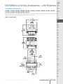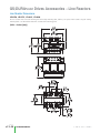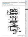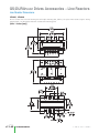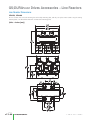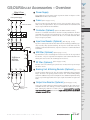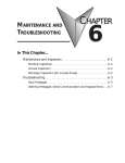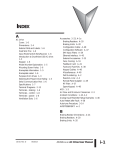
1
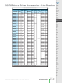
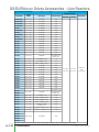
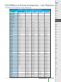
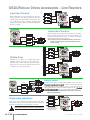
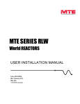
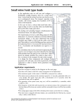
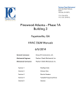
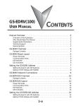
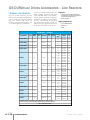
GS/DURAPULSE Drives Accessories – Line Reactors
LR Series Line Reactors
Input line reactors protect the AC drive
from transient overvoltage conditions typically caused by utility capacitor switching.
Input line reactors also reduce the
harmonics associated with AC drives, and
are recommended for all installations.
Output line (load) reactors protect the
motor insulation against AC drive short
circuits and IGBT reflective wave damage,
and also allow the motor to run cooler by
“smoothing” the motor current waveform.
They are recommended for operating
“non-inverter-duty” motors, and for any
motors where the length of wiring between
the AC drive and motor exceeds 75 feet.
Features:
• Universal mounting feet with multiple
mounting slots; can replace most reactors
using existing mounting holes.
• 10-year warranty
Agency Approvals:
• CULUS listed (E197592)
• CE marked
• RoHS
Line Reactors – LR Series
Part Number
Imped
Watt System Phase
Price Rated
Amps -ance Inductance Loss Voltage – Use (1)
1 – In
1 – In
GS1-10P2
GS2-10P2
0.25
0.25
1 – In
1 – In
GS1-10P5
GS2-10P5
0.5
0.5
17.4
1 – In
GS2-11P0
1
11.2
240
1 – In
1 – In
1 – In
GS1-20P2
GS1-20P5
GS2-20P5
0.25
0.5
0.5
GS1-10P2
GS1-10P5
GS2-10P2
GS2-10P5
GS1-20P2
GS1-20P5
GS2-20P5
0.25
0.5
0.25
0.5
0.25
0.5
0.5
LR-10P2-1PH (2)
<--->
5.8
1.58 mH
8.0
LR-10P5-1PH (2)
<--->
9.8
0.93 mH
11.7
LR-11P0-1PH (2)
<--->
16
0.57 mH
LR-20P5-1PH (2)
<--->
4.9
3.74 mH
GS Drive Drive
Model
hp
120
LR-20P5
<--->
2.4
4.2 mH
7
208/240
3 – Out
3 – Out
3 – Out
3 – Out
3 – I/O
3 – I/O
3 – I/O
LR-21P0-1PH (2)
<--->
8
2.29 mH
15.9
240
1 – In
1 – In
1 – In
GS1-21P0
GS2-21P0
GS3-21P0
1
1
1
GS1-21P0
GS2-21P0
GS3-21P0
GS2-11P0
1
1
1
1
3%
LR-21P0
<--->
4.6
2.46 mH
11
208/240
3 – I/O
3 – I/O
3 – I/O
3 – Out
LR-22P0-1PH (2)
<--->
12
1.53 mH
24.3
240
1 – In
1 – In
1 – In
GS1-22P0
GS2-22P0
GS3-22P0
2
2
2
LR-22P0
<--->
7.5
1.35 mH
21
208/240
3 – I/O
3 – I/O
3 – I/O
GS1-22P0
GS2-22P0
GS3-22P0
2
2
2
LR-23P0-1PH (2)
<--->
17
1.08 mH
27.3
240
1 – In
1 – In
GS2-23P0
GS3-23P0
3
3
LR-23P0
<--->
10.6
0.97 mH
38
3 – I/O
3 – I/O
GS2-23P0
GS3-23P0
3
3
LR-25P0
<--->
16.7
0.626 mH
48
3 – I/O
3 – I/O
GS3-25P0
GS2-25P0
5
5
LR-27P5
<--->
24.2
0.434 mH
65
3 – I/O
3 – I/O
GS2-27P5
GS3-27P5
7.5
7.5
208/240
1) Use (side of drive): In = input only; Out = output only; I/O = input or output.
2) Single-phase line reactors should NOT be installed on the output side of AC drives.
*** TABLE CONTINUED NEXT PAGE ***
Volume 13
e13–50
Drives/Motors/Motion
1 - 80 0 - 633 - 0405
GS/DURAPULSE Drives Accessories – Line Reactors
*** TABLE CONTINUED FROM PREVIOUS PAGE ***
Systems
Overview
Line Reactors – LR Series
Part Number
Company
Information
Imped
Watt System Phase
Price Rated
Amps -ance Inductance Loss Voltage – Use (1)
LR-2010
LR-2015
LR-2020
LR-2025
LR-2030
LR-2040
LR-2050
<--->
30.8
0.342 mH
96
GS3-2010
10
<--->
30.8
0.22 mH
64
GS3-2015
15
<--->
59.4
0.172 mH
85
GS3-2020
20
<--->
74.8
0.138 mH
94
GS3-2025
25
208/240
Programmable
Controllers
GS Drive Drive
Model
hp
Field I/O
Software
C-more &
other HMI
<--->
88
0.116 mH
135
GS3-2030
30
<--->
114
0.0886 mH
149
GS3-2040
40
Drives
<--->
143
0.0699 mH
154
GS3-2050
50
Soft
Starters
LR-41P0
<--->
2.1
8.927 mH
10.4
GS2-41P0
GS3-41P0
1
1
LR-42P0
<--->
3.4
5.79 mH
19
GS2-42P0
GS3-42P0
2
2
LR-43P0
<--->
4.8
4.27 mH
23
GS2-43P0
GS3-43P0
3
3
LR-45P0
<--->
7.6
2.77 mH
49
GS2-45P0
GS3-45P0
5
5
LR-47P5
<--->
11
1.68 mH
40
GS2-47P5
GS3-47P5
7.5
7.5
LR-4010
<--->
14
1.29 mH
64
GS2-4010
GS3-4010
10
10
LR-4015
LR-4020
LR-4025
LR-4030
LR-4040
LR-4050
LR-4060
LR-4075
LR-4100
LR-4125
LR-4150
LR-4200
LR-4250
LR-4300
LR-51P0
LR-52P0
LR-53P0
LR-55P0
LR-5010
<--->
21
0.912 mH
65
GS3-4015
15
<--->
27
0.694 mH
79
GS3-4020
20
Encoders
<--->
34
0.569 mH
96
GS3-4025
25
<--->
40
0.469 mH
105
GS3-4030
30
Current
Sensors
<--->
52
0.387 mH
114
GS3-4040
40
<--->
65
0.295 mH
114
GS3-4050
50
<--->
77
0.227 mH
169
GS3-4060
60
<--->
96
0.196 mH
193
GS3-4075
75
<--->
124
0.152 mH
225
GS3-4100
100
<--->
156
0.117 mH
254
<--->
180
0.103 mH
299
<--->
240
0.0839 mH
280
<--->
302
0.0654 mH
<--->
361
0.0565 mH
<--->
1.7
15.9 mH
12
<--->
2.7
9.29 mH
22
<--->
3.9
6.74 mH
23.3
<--->
6.1
4.51 mH
<--->
11
2.47 mH
3%
3 – I/O
480
Motors &
Gearbox
Steppers/
Servos
Motor
Controls
Proximity
Sensors
Photo
Sensors
Limit
Switches
Pressure
Sensors
Temperature
Sensors
Pushbuttons/
Lights
125
Process
150
200
Relays/
Timers
337
250
Comm.
381
300
–
GS2-51P0
1
GS2-52P0
2
GS2-53P0
3
34.7
GS2-55P0
5
43.8
GS2-57P5
7.5
575/600
Terminal
Blocks &
Wiring
Power
Circuit
Protection
Enclosures
1) Use (side of drive): In = input only; Out = output only; I/O = input or output.
Tools
Pneumatics
Appendix
Product
Index
Part #
Index
Volume 13
w w w. a u to m at i o n d i re c t . c o m / d r i ves
Drives/Motors/Motion
e13–51
GS/DURAPULSE Drives Accessories – Line Reactors
Line Reactors – LR Series – Additional Specifications
Part Number
LR-10P2-1PH
LR-10P5-1PH
LR-11P0-1PH
LR-20P5-1PH
LR-20P5
LR-21P0-1PH
LR-21P0
LR-22P0-1PH
LR-22P0
LR-23P0-1PH
LR-23P0
LR-25P0
LR-27P5
LR-2010
LR-2015
LR-2020
Product
Weight
Wire Range
Terminal Torque
2.6 lb [1.2 kg]
#12–#18 AWG
10 lb·in
2.7 lb [1.2 kg]
#12–#18 AWG
10 lb·in
4.2 lb [1.9 kg]
#12–#18 AWG
20 lb·in
2.8 lb [1.3 kg]
#12–#18 AWG
10 lb·in
4.0 lb [1.8 kg]
#12–#18 AWG
10 lb·in
2.8 lb [1.3 kg]
#12–#18 AWG
10 lb·in
4.0 lb [1.8 kg]
#12–#18 AWG
10 lb·in
4.3 lb [2.0 kg]
#12–#18 AWG
20 lb·in
4.0 lb [1.8 kg]
#12–#18 AWG
10 lb·in
4.3 lb [2.0 kg]
#12–#18 AWG
20 lb·in
4.0 lb [1.8 kg]
#12–#18 AWG
10 lb·in
8.0 lb [3.6 kg]
#18–#4 AWG
20 lb·in
8.0 lb [3.6 kg]
#18–#4 AWG
20 lb·in
12 lb [5.4 kg]
#18–#4 AWG
20 lb·in
12 lb [5.4 kg]
#18–#4 AWG
20 lb·in
12 lb [5.4 kg]
#18–#4 AWG
20 lb·in
LR-2025
15 lb [6.8 kg]
#18–#4 AWG
#18–#16 AWG: 25 lb·in
#14–#6 AWG: 30 lb·in
#4 AWG: 35 lb·in
LR-2030
LR-2040
LR-2050
LR-41P0
LR-42P0
LR-43P0
LR-45P0
LR-47P5
LR-4010
LR-4015
LR-4020
LR-4025
LR-4030
LR-4040
33 lb [15 kg]
2/0 – #6AWG (AL or CU)
120
33 lb [15 kg]
2/0 – #6AWG (AL or CU)
120
36 lb [16 kg]
250kcmil – #6AWG (AL or CU)
275
4.0 lb [1.8 kg]
#12–#18 AWG
10 lb·in
4.0 lb [1.8 kg]
#12–#18 AWG
10 lb·in
4.0 lb [1.8 kg]
#12–#18 AWG
10 lb·in
4.0 lb [1.8 kg]
#12–#18 AWG
10 lb·in
4.0 lb [1.8 kg]
#12–#18 AWG
10 lb·in
4.0 lb [1.8 kg]
#12–#18 AWG
10 lb·in
8.0 lb [3.6 kg]
#18–#4 AWG
20 lb·in
8.0 lb [3.6 kg]
#18–#4 AWG
20 lb·in
10 lb [4.5 kg]
#18–#4 AWG
20 lb·in
10 lb [4.5 kg]
#18–#4 AWG
20 lb·in
15 lb [6.8 kg]
#18–#4 AWG
20 lb·in
#22–#4 AWG
#22–#16 AWG: 25 lb·in
#14–#6 AWG: 30 lb·in
#4 AWG: 35 lb·in
33 lb [15 kg]
2/0 – #6AWG (AL or CU)
120 lb·in
46 lb [21 kg]
250kcmil – #6AWG (AL or CU)
275 lb·in
46 lb [21 kg]
250kcmil – #6AWG (AL or CU)
275 lb·in
46 lb [21 kg]
250kcmil – #6AWG (AL or CU)
275 lb·in
LR-4200
74 lb [34 kg]
(1) 600kcmil – #4 AWG
(2) 250kcmil – 1/0
500 lb·in
LR-4250
LR-4300
LR-51P0
LR-52P0
LR-53P0
LR-55P0
LR-5010
74 lb [34 kg]
(2)* 350kcmil – #4 AWG (AL or CU)
275 lb·in
74 lb [34 kg]
(2)* 350kcmil – #4 AWG (AL or CU)
275 lb·in
4.0 lb [1.8 kg]
#12–#18 AWG
10 lb·in
LR-4050
LR-4060
LR-4075
LR-4100
LR-4125
LR-4150
25 lb [11 kg]
Temperature Range
Operating
Storage
Environment
-40 – 104 °F
[-40 – 40 °C]
NEMA: open
IP00
no corrosive gases
-40 – 149 °F
[-40 – 65 °C]
* LR-4250 & LR-4300 have dual-connector lugs, and will require multiple conductors per phase of the appropriate size to fit the lugs.
Volume 13
e13–52
Drives/Motors/Motion
1 - 80 0 - 633 - 0405
GS/DURAPULSE Drives Accessories – Line Reactors
Line Reactor Part Number Cross Reference
Company
Information
Systems
Overview
Line Reactors – LR Series – Part Number Cross Reference
AutomationDirect
LR Series
LR-10P2-1PH
LR-10P5-1PH
LR-11P0-1PH
LR-20P5-1PH
LR-20P5
LR-21P0-1PH
LR-21P0
LR-22P0-1PH
LR-22P0
LR-23P0-1PH
LR-23P0
LR-25P0
LR-27P5
LR-2010
LR-2015
LR-2020
LR-2025
LR-2030
LR-2040
LR-2050
LR-41P0
LR-42P0
LR-43P0
LR-45P0
LR-47P5
LR-4010
LR-4015
LR-4020
LR-4025
LR-4030
LR-4040
LR-4050
LR-4060
LR-4075
LR-4100
LR-51P0
LR-52P0
LR-53P0
LR-55P0
LR-5010
LR-4125
LR-4150
LR-4200
LR-4250
LR-4300
AutomationDirect
GS Series (legacy)
AB-1321
Hammond
MTE-RL
Programmable
Controllers
MTE-RLW
GS-10P2-LR
NA
NA
NA
NA
GS-10P5-LR
NA
NA
NA
NA
GS-11P0-LR
NA
NA
NA
NA
GS-20P5-LR-1PH
NA
NA
NA
NA
GS-20P5-LR-3PH
NA
NA
NA
NA
GS-21P0-LR-1PH
NA
NA
NA
NA
GS-21P0-LR-3PH
1321-3R4-A
RM0004N30
RL-00401
RLW-04P801
GS-22P0-LR-1PH
NA
NA
NA
NA
GS-22P0-LR-3PH
1321-3R8-A
RM0008N15
RL-00801
RLW-07P601
GS-23P0-LR-1PH
NA
NA
NA
NA
GS-23P0-LR-3PH
1321-3R12-A
RM0012N13
RL-01201
RLW-001101
GS-25P0-LR
1321-3R18-A
RM0018P80
RL-01801
RLW-001401
GS-27P5-LR
1321-3R25-A
RM0025P50
RL-02501
RLW-002101
GS-2010-LR
1321-3R35-A
RM0035P40
RL-03501
RLW-003501
GS-2015-LR
1321-3R45-A
RM0045P30
RL-04501
RLW-004601
GS-2020-LR
1321-3R55-A
RM0055P25
RL-05501
RLW-005501
GS-2025-LR
1321-3R80-A
RM0080P20
RL-08001
RLW-008301
GS-2030-LR
1321-3R100-A
RM0080P20
RL-10001
RLW-010401
GS-2040-LR
1321-3R130-A
RM0130P10
RL-13001
RLW-013001
GS-2050-LR
1321-3R130-A
RM0130P10
RL-13001
RLW-013001
GS-41P0-LR
1321-3R1-B
RM0002M12
RL-00201
RLW-02P103
GS-42P0-LR
1321-3R4-B
RM0004N65
RL-00402
RLW-04P805
GS-43P0-LR
1321-3R4-B
RM0008N50
RL-00402
RLW-04P805
GS-45P0-LR
1321-3R8-B
RM0008N30
RL-00802
RLW-07P603
GS-47P5-LR
1321-3R12-B
RM0012N25
RL-01202
RLW-001103
GS-4010-LR
1321-3R18-B
RM0018N15
RL-01802
RLW-001403
Pushbuttons/
Lights
GS-4015-LR
1321-3R25-B
RM0025N12
RL-02502
RLW-002103
Process
GS-4020-LR
1321-3R35-B
RM0035P80
RL-03502
RLW-003503
GS-4025-LR
1321-3R35-B
RM0035P80
RL-03502
RLW-003503
Relays/
Timers
GS-4030-LR
1321-3R45-B
RM0045P70
RL-04502
RLW-004603
Comm.
GS-4040-LR
1321-3R55-B
RM0055P50
RL-05502
RLW-005503
GS-4050-LR
1321-3R80-B
RM0080P40
RL-08002
RLW-008305
GS-4060-LR
1321-3R80-B
RM0080P40
RL-08002
RLW-008305
GS-4075-LR
1321-3R100-B
RM0110P30
RL-10002
RLW-010403
Power
GS-4100-LR
1321-3R130-B
RM0130P20
RL-13002
RLW-013003
Circuit
Protection
GS-51P0-LR
1321-3R2-B
RM0002M20
RL-00202
RLW-02P105
GS-52P0-LR
1321-3R4-C
RM0004M12
RL-00403
RLW-04P806
Enclosures
N/A
1321-3R4-C
RM0004N91
RL-00403
RLW-04P806
Tools
N/A
1321-3R8-C
RM0008N50
RL-00803
RLW-07P605
N/A
1321-3R12-B
RM0012N25
RL-01202
RLW-001103
N/A
1321-3R160-B
RM0160P15
RL-16002
RLW-016003
N/A
1321-3R200-B
RM0200P11
RL-20002B14
RLW-020003
N/A
1321-3RB250-B
RM0250U90
RL-25002B14
RLW-025003
N/A
1321-3RB320-B
RM0320U75
RL-32002B14
RLW-032203
N/A
1321-3RB400-B
RM0400U61
RL-40002B14
RLW-041403
Field I/O
Software
C-more &
other HMI
Drives
Soft
Starters
Motors &
Gearbox
Steppers/
Servos
Motor
Controls
Proximity
Sensors
Photo
Sensors
Limit
Switches
Encoders
Current
Sensors
Pressure
Sensors
Temperature
Sensors
Terminal
Blocks &
Wiring
Pneumatics
Appendix
Product
Index
Part #
Index
Volume 13
w w w. a u to m at i o n d i re c t . c o m / d r i ves
Drives/Motors/Motion
e13–53
GS/DURAPULSE Drives Accessories – Line Reactors
Input side of the drive
When installed on the input side of the AC drive, line
reactors will reduce line notching, and limit current and
voltage spikes and surges from the incoming line. The
line reactor will also reduce harmonic distortion from
the drive onto the line. Units are installed in front of the
AC drive as shown.
C1
C2
L3
B1
B2
L2
A1
A2
L1
T3
T2
T1
Output side of the drive
T3
C1
C2
T2
B1
B2
T1
A1
A2
When installed on the output side of the drive, line reactors
protect the drive from short circuits at the load. Voltage and
current waveforms from the drive are enhanced, reducing
motor overheating and noise emissions.
Note: Single phase line reactors should NOT be installed on the output of the
AC drive. Use only three-phase reactors on drive outputs, and only for
three-phase motors.
C1
C2
L3
B1
B2
L2
A1
A2
L1
C1
C2
L3
B1
B2
L2
A1
A2
L1
T3
T2
T1
Multiple drives
Individual line reactors are recommended when
installing multiple drives on the same power line.
Individual line reactors eliminate crosstalk between
multiple drives and provide isolated protection for
each drive for its own specific load.
T3
T2
T1
OL1
Multiple motors
OL2
A single reactor can be used for multiple motors on the same drive,
if the motors operate simultaneously. Size the reactor based upon the
total horsepower of all the motors. Select a reactor with a current
rating greater than the sum of the motor full-load currents. Overload
relays are recommended for use in multi-motor applications.
Reactor
T3 C1
C2
T2 B1
B2
T1 A1
A2
Single phase applications
Some of the line reactors are listed for use with single-phase
input power. Make sure that terminals B1 and B2, if present, are
properly insulated before any connections are made.
WARNING: Please ensure that terminals B1 and B2 are properly
insulated before making any connections to single-phase power.
Note: A single reactor should be used with multiple motors only when the motors will
always operate simultaneously.
C1
C2
B1*
B2*
L2
T3
T2
A1
A2
L1
T1
*GS series legacy 1-phase reactors
include a B-phase winding.
*LR series 1-phase reactors do not
include a B-phase winding.
Volume 13
e13–54
Drives/Motors/Motion
1 - 80 0 - 633 - 0405
GS/DURAPULSE Drives Accessories – Line Reactors
Company
Information
Line Reactor Dimensions
Systems
Overview
LR-10P2-1PH, LR-10P5-1PH, LR-20P5-1PH, LR-21P0-1PH
Programmable
Controllers
LR series reactors have universal mounting feet with multiple mounting slots, and they can replace most reactors using the existing
mounting holes. Use four bolts to mount the reactors to the mounting panel.
(Units = inches [mm])
Field I/O
Software
4.18
[106.2]
C-more &
other HMI
3.75
[95.3]
Drives
Soft
Starters
Motors &
Gearbox
3.75
[95.3]
Steppers/
Servos
Motor
Controls
Proximity
Sensors
Photo
Sensors
Limit
Switches
A1
B1
Encoders
4.00
[101.6]
Current
Sensors
A2
B2
Pressure
Sensors
Temperature
Sensors
3.05
[77.5]
1.44
[36.6]
Pushbuttons/
Lights
2.00
[50.8]
MOUNTING
Process
Relays/
Timers
1.44
[36.6]
Comm.
Terminal
Blocks &
Wiring
Power
2.00
[50.8]
MOUNTING
1.64
[41.7]
Circuit
Protection
Enclosures
Tools
4X Ø0.25
[Ø6.4]
0.88
[22.4]
Pneumatics
0.31
[7.9]
Appendix
Product
Index
Part #
Index
Volume 13
w w w. a u to m at i o n d i re c t . c o m / d r i ves
Drives/Motors/Motion
e13–55
GS/DURAPULSE Drives Accessories – Line Reactors
Line Reactor Dimensions
LR-11P0-1, LR-22P0-1PH, LR-23P0-1PH
LR series reactors have universal mounting feet with multiple mounting slots, and they can replace most reactors using the existing
mounting holes. Use four bolts to mount the reactors to the mounting panel.
(Units = inches [mm])
6.00
[152.4]
4.81
[122.2]
4.00
[101.6]
A1
B1
A2
B2
5.00
[127.0]
2.50
[63.5]
12X 0.31
[7.9]
2.50
[63.5]
2.50
[63.5]
MOUNTING
3.19
[81.0]
2.00
[50.8]
MOUNTING
4X Ø0.25
[Ø6.4]
3.20
[81.3]
Volume 13
e13–56
Drives/Motors/Motion
1 - 80 0 - 633 - 0405
GS/DURAPULSE Drives Accessories – Line Reactors
Company
Information
Line Reactor Dimensions
Systems
Overview
LR-20P5, LR-21P0, LR-22P0, LR-23P0, LR-41P0, LR-42P0, LR-43P0, LR-45P0, LR-47P5, LR-4010,
LR-51P0, LR-52P0, LR-53P0, LR-55P0, LR-5010
Programmable
Controllers
LR series reactors have universal mounting feet with multiple mounting slots, and they can replace most reactors using the existing
mounting holes. Use four bolts to mount the reactors to the mounting panel.
Field I/O
Software
(Units = inches [mm])
C-more &
other HMI
Drives
Soft
Starters
Motors &
Gearbox
Steppers/
Servos
Motor
Controls
Proximity
Sensors
Photo
Sensors
Limit
Switches
Encoders
Current
Sensors
Pressure
Sensors
Temperature
Sensors
Pushbuttons/
Lights
Process
Relays/
Timers
Comm.
Terminal
Blocks &
Wiring
Power
Circuit
Protection
Enclosures
Tools
Pneumatics
Appendix
Product
Index
Part #
Index
Volume 13
w w w. a u to m at i o n d i re c t . c o m / d r i ves
Drives/Motors/Motion
e13–57
GS/DURAPULSE Drives Accessories – Line Reactors
Line Reactor Dimensions
LR-25P0, LR-27P5, LR-4015, LR-4020
LR series reactors have universal mounting feet with multiple mounting slots, and they can replace most reactors using the existing
mounting holes. Use four bolts to mount the reactors to the mounting panel.
(Units = inches [mm])
Volume 13
e13–58
Drives/Motors/Motion
1 - 80 0 - 633 - 0405
GS/DURAPULSE Drives Accessories – Line Reactors
Company
Information
Line Reactor Dimensions
Systems
Overview
LR-2010, LR-2015, LR-2020, LR-4025, LR-4030
Programmable
Controllers
LR series reactors have universal mounting feet with multiple mounting slots, and they can replace most reactors using the existing
mounting holes. Use four bolts to mount the reactors to the mounting panel.
(Units = inches [mm])
Field I/O
Software
C-more &
other HMI
Drives
Soft
Starters
Motors &
Gearbox
Steppers/
Servos
Motor
Controls
Proximity
Sensors
Photo
Sensors
Limit
Switches
Encoders
Current
Sensors
Pressure
Sensors
Temperature
Sensors
Pushbuttons/
Lights
Process
Relays/
Timers
Comm.
Terminal
Blocks &
Wiring
Power
Circuit
Protection
Enclosures
Tools
Pneumatics
Appendix
Product
Index
Part #
Index
Volume 13
w w w. a u to m at i o n d i re c t . c o m / d r i ves
Drives/Motors/Motion
e13–59
GS/DURAPULSE Drives Accessories – Line Reactors
Line Reactor Dimensions
LR-2025, LR-4040
LR series reactors have universal mounting feet with multiple mounting slots, and they can replace most reactors using the existing
mounting holes. Use four bolts to mount the reactors to the mounting panel.
(Units = inches [mm])
Volume 13
e13–60
Drives/Motors/Motion
1 - 80 0 - 633 - 0405
GS/DURAPULSE Drives Accessories – Line Reactors
Company
Information
Line Reactor Dimensions
Systems
Overview
LR-2030, LR-2040, LR-4075
Programmable
Controllers
LR series reactors have universal mounting feet with multiple mounting slots, and they can replace most reactors using the existing
mounting holes. Use four bolts to mount the reactors to the mounting panel.
(Units = inches [mm])
Field I/O
Software
C-more &
other HMI
Drives
Soft
Starters
Motors &
Gearbox
Steppers/
Servos
Motor
Controls
Proximity
Sensors
Photo
Sensors
Limit
Switches
Encoders
Current
Sensors
Pressure
Sensors
Temperature
Sensors
Pushbuttons/
Lights
Process
Relays/
Timers
Comm.
Terminal
Blocks &
Wiring
Power
Circuit
Protection
Enclosures
Tools
Pneumatics
Appendix
Product
Index
Part #
Index
Volume 13
w w w. a u to m at i o n d i re c t . c o m / d r i ves
Drives/Motors/Motion
e13–61
GS/DURAPULSE Drives Accessories – Line Reactors
Line Reactor Dimensions
LR-2050
LR series reactors have universal mounting feet with multiple mounting slots, and they can replace most reactors using the existing
mounting holes. Use four bolts to mount the reactors to the mounting panel.
(Units = inches [mm])
Volume 13
e13–62
Drives/Motors/Motion
1 - 80 0 - 633 - 0405
GS/DURAPULSE Drives Accessories – Line Reactors
Company
Information
Line Reactor Dimensions
Systems
Overview
LR-4050, LR-4060
Programmable
Controllers
LR series reactors have universal mounting feet with multiple mounting slots, and they can replace most reactors using the existing
mounting holes. Use four bolts to mount the reactors to the mounting panel.
(Units = inches [mm])
Field I/O
Software
C-more &
other HMI
Drives
Soft
Starters
Motors &
Gearbox
Steppers/
Servos
Motor
Controls
Proximity
Sensors
Photo
Sensors
Limit
Switches
Encoders
Current
Sensors
Pressure
Sensors
Temperature
Sensors
Pushbuttons/
Lights
Process
Relays/
Timers
Comm.
Terminal
Blocks &
Wiring
Power
Circuit
Protection
Enclosures
Tools
Pneumatics
Appendix
Product
Index
Part #
Index
Volume 13
w w w. a u to m at i o n d i re c t . c o m / d r i ves
Drives/Motors/Motion
e13–63
GS/DURAPULSE Drives Accessories – Line Reactors
Line Reactor Dimensions
LR-4100, LR-4125, LR-4150
LR series reactors have universal mounting feet with multiple mounting slots, and they can replace most reactors using the existing
mounting holes. Use four bolts to mount the reactors to the mounting panel.
(Units = inches [mm])
Volume 13
e13–64
Drives/Motors/Motion
1 - 80 0 - 633 - 0405
GS/DURAPULSE Drives Accessories – Line Reactors
Company
Information
Line Reactor Dimensions
Systems
Overview
LR-4200
Programmable
Controllers
LR series reactors have universal mounting feet with multiple mounting slots, and they can replace most reactors using the existing
mounting holes. Use four bolts to mount the reactors to the mounting panel.
(Units = inches [mm])
Field I/O
Software
10.12
[257.1]
C-more &
other HMI
Drives
Soft
Starters
Motors &
Gearbox
6.76
[171.7]
9.00
[228.6]
Steppers/
Servos
Motor
Controls
Proximity
Sensors
Photo
Sensors
Limit
Switches
Encoders
Current
Sensors
Pressure
Sensors
9.00
[228.6]
Temperature
Sensors
5.75
[146.2]
Pushbuttons/
Lights
1.76
[44.7]
Process
Relays/
Timers
3.52
[89.5]
3.52
[89.5]
Comm.
0.50
[12.7]
Terminal
Blocks &
Wiring
Power
5.64
[143.3]
4.20
[106.6]
MOUNTING
Circuit
Protection
4.25
[108.0]
Enclosures
Tools
Pneumatics
2.33
[59.2]
Appendix
3.60
[91.4]
MOUNTING
4.75
[120.6]
Product
Index
Part #
Index
Volume 13
w w w. a u to m at i o n d i re c t . c o m / d r i ves
Drives/Motors/Motion
e13–65
GS/DURAPULSE Drives Accessories – Line Reactors
Line Reactor Dimensions
LR-4250, LR-4300
LR series reactors have universal mounting feet with multiple mounting slots, and they can replace most reactors using the existing
mounting holes. Use four bolts to mount the reactors to the mounting panel.
(Units = inches [mm])
Volume 13
e13–66
Drives/Motors/Motion
1 - 80 0 - 633 - 0405
GS/DURAPULSE Accessories – Overview
Accessories – Part
numbering system
GS - 22P0 - LR - 3PH
Description Code (optional)
1PH: Single phase 3PH: Three phase
ENC: Enclosure
Blank: For reactor, blank = 3-phase
Accessory Code
BR: Braking resistor BZL: Bezel CBL: Cable DBU: Dynamic Brake Unit
EDRV: Ethernet board FB: Feedback board FKIT: Fuse Kit FUSE: Replacement fuses for FKIT
KPD: Keypad LR: Line reactor (legacy) RS: Recommended Standard
Note: With the exception of the EMI filters,
RF filters, and LR series line reactors,
each accessory part number begins with
GS, followed by the AC Drive rating, and
then the relevant accessory code.
Following the accessory code, you will
find a description code when applicable.
The diagram at right shows the accessory
part numbering system.
Horsepower Rating
Example: 2P0 = 2.0 hp
7P5 = 7.5 hp
010 = 10 hp
Voltage Rating
1: 115V
2: 230V
4: 460V
5: 575V
Series
GS: All GS and DURApulse Series Drives
GS1: GS1 Series GS2: GS2 Series GS3: DURApulse Series
Under 20hp
LR: Newer line reactor series
Power Supply
Please follow the specific power supply requirements shown in Chapter 1 and the
Warning section of the applicable GS or DURAPULSE AC Drives User Manual.
From power supply
1
(Refer to page 13–81.)
Input fuses protect the AC drive from excessive input current due to line surges, short
circuits, and ground faults. They are recommended for all installations and may be
required for UL-listed installations. (AutomationDirect fuses are not available for GS1
drives.)
Disconnect switch
2
3
Fuses
Contactor (Optional)
(Refer to the Motor Controls section.)
Do not use a contactor or disconnect switch for run/stop control of the AC drive and
motor. This will reduce the operating life cycle of the AC drive. Cycling a power circuit
switching device while the AC drive is in run mode should be done only in emergency
situations.
4
6
5
L1
L2
+
(–)
T2
7
(Refer to page 13–74.)
RF filter (Optional)
(Refer to page 13–80.)
RF filters reduce the radio frequency interference or noise on the input or output side of
the inverter.
T3
6
EMI filter (Optional)
Input EMI filters reduce electromagnetic interference or noise on the input side of the AC
drive. They are required for CE compliance and recommended for installations prone
to or sensitive to electromagnetic interference. (Separate EMI filters are not neccessary
for GS1 drives.)
B1
B2
T1
(Refer to page 13–50.)
Input line reactors protect the AC drive from transient overvoltage conditions, typically
caused by utility capacitor switching. The input line reactor also reduces the harmonics
associated with AC drives. Input line reactors are recommended for all installations.
L3
GS and
DURAPULSE
AC Drive
GSx-xxxx
Input Line Reactor (Optional)
Braking Resistor (Optional)
(Refer to page 13–69.)
Dynamic braking allows the AC drive to produce additional braking (stopping) torque.
AC drives can typically produce between 15% & 20% braking torque without the addition of any external components. The addition of optional braking may be required for
applications that require rapid deceleration or high inertia loads. (Braking resistors are
not available for GS1 drives.)
8
Motor
Motor grounding
terminal
Output Line Reactor (Optional)
(Refer to page 13–50.)
Output line reactors protect the motor insulation against AC drive short circuits and
IGBT reflective wave damage, and also “smooth” the motor current waveform, allowing
the motor to run cooler. They are recommended for operating “non-inverter-duty”
motors and when the length of wiring between the AC drive and motor exceeds 75 feet.
Volume 13
e13–46
Drives/Motors/Motion
1 - 80 0 - 633 - 0405
GS/DURAPULSE Accessories – Overview
20hp & Over
(DURAPULSE only)
Company
Information
Systems
Overview
Power Supply
Please follow the specific power supply requirements shown in Chapter 1 of the
DURAPULSE AC Drives User Manual.
From power supply
1
Field I/O
(Refer to page 13–81.)
Input fuses protect the AC drive from excessive input current due to line surges,
short circuits, and ground faults. They are recommended for all installations and
may be required for UL-listed installations.
Disconnect switch
2
Fuses
Contactor (Optional) (Refer to the Motor Controls section.)
Do not use a contactor or disconnect switch for run/stop control of the AC drive
and motor. This will reduce the operating life cycle of the AC drive. Cycling a
power circuit switching device while the AC drive is in run mode should be done
only in emergency situations.
3
4
6
Input Line Reactor (Optional) (Refer to page 13–50.)
Input line reactors protect the AC drive from transient overvoltage conditions, typically caused by utility capacitor switching. The input line reactor also reduces the
harmonics associated with AC drives. Input line reactors are recommended for all
installations.
5
L1
L2
+
DURAPULSE
AC Drive
GS3-xxxx
7
T2
T3
8
Drives
Soft
Starters
Motors &
Gearbox
Steppers/
Servos
Motor
Controls
Proximity
Sensors
RF filter (Optional)
Limit
Switches
Encoders
Current
Sensors
Braking Unit & Braking Resistor (Optional) (pg 13–67)
Dynamic braking allows the AC drive to produce additional braking (stopping)
torque. AC drives can typically produce between 15% & 20% braking torque
without the addition of any external components. The addition of optional braking
may be required for applications that require rapid deceleration or high inertia
loads.
6
C-more &
other HMI
(Refer to page 13–80.)
RF filters reduce the radio frequency interference or noise on the input or output
side of the inverter.
–
T1
EMI filter (Optional) (Refer to page 13–74.)
Input EMI filters reduce electromagnetic interference or noise on the input side of
the AC drive. They are required for CE compliance and recommended for installations prone to or sensitive to electromagnetic interference.
+2
Software
Photo
Sensors
L3
Programmable
Controllers
Pressure
Sensors
Temperature
Sensors
Pushbuttons/
Lights
Process
Relays/
Timers
Comm.
Motor
Motor grounding
terminal
Output Line Reactor (Optional)
(Refer to page 13–50.)
Output line reactors protect the motor insulation against AC drive short circuits
and IGBT reflective wave damage, and also “smooth” the motor current waveform, allowing the motor to run cooler. They are recommended for operating
“non-inverter-duty” motors and when the length of wiring between the AC drive
and motor exceeds 75 feet.
Terminal
Blocks &
Wiring
Power
Circuit
Protection
Enclosures
Tools
Pneumatics
Appendix
Product
Index
Part #
Index
Volume 13
w w w. a u to m at i o n d i re c t . c o m / d r i ves
Drives/Motors/Motion
e13–47