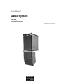
1
User Manual
Galeo System
Galeo Cylindric Wave Unit
Galeo Sub
Galeo Flying Frame
Galeo Sub Flying Frame
Last updated: 09/2008
Contents
Foreword ................................................................................ 3
Part 1 – General Information
Components........................................................................... 4
Safety instructions .................................................................. 5
Coverage................................................................................ 6
Possible combinations, groundstack Galeo ............................. 7
Combination with Galeo XT .................................................... 9
Part 2 – Assembly and Rigging
Transportation ...................................................................... 10
EASE Focus......................................................................... 11
Assembly and disassembly, flown operation ......................... 12
Assembly and disassembly, groundstack operation .............. 15
Part 3 – System Start-up
System rack.......................................................................... 16
Controller setups .................................................................. 17
Cabling................................................................................. 18
Sound optimisation ............................................................... 19
2
SEEBURG acoustic line
Foreword
The GALEO Line Array System is suitable for a wide range of sound
applications for which a fast set-up, high sound quality, long throw and
predictable directivity are crucial. It is particularly suitable for high-end
permanent installations.
The Galeo Sub with integrated flying hardware for flown array applications and
groundstack operation serves as a bass extension. Thanks to hornloaded
bandpass technology in conjunction with the 18“ ND long excursion chassis
with exceptionally powerful drive conceived exclusively for this unit, the Galeo
Sub offers a high level of bass, lowest distortion and a long throw.
Please read this user manual carefully and follow the instructions provided. It
should be within reach at all time when setting up the Galeo system in order to
be able to find a solution to any queries.
With the purchase of a Galeo system you will have also received a structural
analysis certificate that will provide information on the materials used and their
maximum resilience.
Should you require additional information or have any helpful suggestions
regarding this user manual, please contact
SEEBURG acoustic line Produktions- und Vertriebsgesellschaft mbH
Auweg 32
89250 Senden-Freudenegg
Germany
07307 / 9700 – 0
www.seeburg.net
[email protected]
3
SEEBURG acoustic line
Part 1 – General Information
Components
The Galeo system comprises the Galeo Cylindric Wave Units and a compatible
Galeo Sub bass extension of the same width and includes appropriate flying
hardware.
Die Galeo Cylindric Wave unit is to be understood as an individual element
within a line array sound system. In combination with several different units, a
cylindrical sound wave is emitted, especially within the mid and high ranges,
which has a longer throw than comparable omni-directional systems. The 3point flying hardware with ball lock pins allows simple and fast assembly,
facilitating curving angles between 0° and 7° in 1° stages.
The exclusive use of high-grade European-made components guarantees a
high maximum sound pressure level with even horizontal directivity and
excellent sound quality.
A Galeo unit is fitted with two 8“ low-mid drivers and one 1.4“ HF driver. The
acoustic crossover frequency is approximately 900 Hz.
The two-way active operation is effected via system amping.
The chassis, which is made of an aluminium and multilayered birch multiplex
composite is polyurea-coated, providing it with adequate protection against
rain. Likewise, all diaphragms have a special coating.
The flying fittings are made of powder-coated steel, which also renders them
weather resistant. However, after many years of use the coating of the fittings
can become damaged and a light rust film may form on the steel parts if
exposed to dampness for longer periods. Therefore, keep your Galeo system
dry at all times and treat all critical areas regularly with suitable care products.
The Galeo Sub features two 18“ cone drivers and covers a frequency range
from 35 Hz to 80 Hz.
4
SEEBURG acoustic line
Safety instructions
PA systems the size of the Galeo pose different types of risk:
- aurally
Even at a low power input the Galeo unit can produce a hazardous sound
pressure level that may cause acute and permanent damage to the ear.
Never sit or stand in the immediate vicinity of the loudspeaker during
operation and always wear ear protection.
Observe the respective German trade association regulation BGV B3
pertaining to noise
- mechanical
During assembly and disassembly, moveable devices and falling parts may
cause serious physical injury.
Observe the respective German trade association regulation BGV D8
pertaining to winches and hoisting gear (basic principles of prevention) as well
as those regarding event and production facilities for the performing arts.
- magnetic and electrical
Even if not connected to a power source, loudspeakers produce a static
magnetic field that can damage cards with a magnetic strip or delete sound
recordings and the like. Amplifiers can emit dangerous voltage. This voltage is
also present on free loudspeaker connectors. It is vital that these connectors
are covered when not used or in wet conditions.
Observe the safety instructions of the amplifier manufacturer and the
respective German trade association regulation BGV A2 pertaining to electrical
equipment and utilities.
Assembly and disassembly of a Galeo PA system must be carried out only by
qualified personnel who are familiar with the corresponding regulations and
adhere to and act in accordance with them. Please note that all quoted
regulations are predominantly applicable in Germany. Work in compliance with
the regulations applicable in the country you are in.
5
SEEBURG acoustic line
Coverage
In the case of large format PA systems, coverage is of the utmost importance.
Very few listeners stand or sit directly within the axis of a line array system.
Consequently, when developing the Galeo our engineers attached great
importance to achieving totally symmetrical coverage that is evenly and
horizontally distributed across the entire frequency range.
The midrange drivers feature cover panels according to the AMR™ (Air Mass
Reflection) principle, which serve at the same time as sound guidance for the
HF drivers.
Due to the specific arrangement, depth and quantity of boreholes, an ideal ratio
between sound passage for the low-mid range and horn guidance for the high
range is obtained.
The Galeo comes as standard with cover panels with which even coverage of
around 120° is achieved within the mid-high range (Art. Nr. 00400). By
exchanging the 120° panels for panels with an 80° horn function, the nominal
coverage angle can be modified accordingly (Art. Nr. 0400/80). This
modification is particularly useful in the case of the upper units of a line array
system, when a broad coverage angle is not required but throw is to be
increased. The front guard is held in place by 4 small neodymium magnets and
secured via a steel cable (safety).
Vertical coverage is adjusted by curving and the angle of inclination (see EASE
FOCUS).
Normally, the Galeo Sub has almost omni-directional sound distribution with a
attenuation of –6 dB on the back side.
When using several Galeo Sub dps, the active version of the Galeo Sub
featuring integrated power amps, it is possible to achieve kidney-shaped
coverage. Behind the loudspeakers there is a broadband cancellation of
approximately 20dB. This mode of operation is to be selected when the sound
level produced by the subwoofer behind the loudspeaker box is considered
unpleasant. For further information refer to the Galeo Sub dp user manual.
Likewise, the coverage angle of subwoofers can also be influenced by specific
positioning and corresponding delays.
6
SEEBURG acoustic line
Possible combinations, groundstack Galeo
The lower cut-off frequency of the Galeo Cylindric Wave Unit is approximately
80Hz. Therefore, trouble-free speech or general corporate applications are
possible without using an additional subwoofer.
However, in the case of disco or live events, the Galeo Sub will be required as
an additional sub-bass extension. Fundamentally, there are three possibilities
of combining the Galeo with the Galeo Sub.
1. Galeo Sub and Galeo flown applications
Use the Galeo Sub flying frame Art. No. 01389 and hang the required number
of woofers below it. A further Galeo Sub flying frame, to which Galeo units are
attached, is mounted below the lowermost Galeo Sub. It is essential that you
observe the permitted total load stipulated in the structural analysis certificate
and the warning notices provided by EASE Focus.
The best acoustic results are obtained if both Galeo Sub and Galeo are flown
within the immediate vicinity of each other (one below the other). Within the
crossover frequency all sound emitting sources are close together in relation to
the wavelength, resulting in an optimum addition. However, flown operation of
basses does not facilitate ground-coupling. Therefore, the maximum level is
lower in comparison to groundstack operation.
Never hang a Galeo Sub on the stacking device below a Galeo line array.
2. Galeo Sub stacked, Galeo flown
In practice, this arrangement is the most frequently used. Through curving and
the angle of inclination of the flown Galeo, it is possible to achieve an ideal
alignment of the mid-high range, whilst the directivity of the Galeo Sub can be
influenced by differing line-up and delays. In addition, due to the comparably
low crossover frequency of 80Hz, the subwoofers are normally not locatable.
Thanks to the steep crossover of 24dB/oct, interference between the Galeo
and the Galeo Sub is kept to a minimum.
7
SEEBURG acoustic line
3. Galeo Sub und Galeo stacked
For groundstack operation of Galeo on top of Galeo Sub no frame is required.
The Galeo units are mounted directly onto the stacking device of the Galeo
Sub and the front spacer. This device offers a wide angular adjustment range
so that the lowermost unit can also be inclined downwards on high
groundstacks.
Observe the maximum stacking height for open-air events (danger in strong
winds) and secure the entire stack in such a way as to exclude the possibility of
toppling or movement.
For inclination angles ranging from 3.5° to – 3.5° the stacking device rests on
the upper steel plate and is secured using the ball lock pin.
In the case of larger inclination angles ranging from -6° bis -12° the spacer of
the Galeo is inserted into the stacking device and secured using the ball lock
pin.
Alternatively, the Galeo flying frame can be extended into a stacking frame, so
that it is also possible to stack the Galeo without the Galeo Sub. This set-up
can then be mounted on TSE infra bass extensions placed horizontally on the
floor.
For smaller sound applications a speaker pole can be screwed into the M20
thread of the Galeo Sub. The flying shackle Art. Nr. 01385 can be used for
assembling up to two Galeo units.
8
SEEBURG acoustic line
The Galeo combined with the Galeo XT
Using a transition cradle Art. No. 01392, Galeo units can also be flown below a
Galeo XT line array. Due to the specific geometry of the transition cradle, the
cylindrical sound source within the mid-high range is continued; it can therefore
be employed for virtually gapless down-fill operation with strong curving.
Featuring the same high frequency drivers and the same midrange driver
arrangement, the Galeo can be regarded as the the Galeo XT’s “little brother”.
Therefore, the Galeo can by all means be additionally employed when the
given maximum level requirements within the mid-high range cannot be
achieved using the Galeo XT on its own, or if strong curving is desired at the
lower end of the line array. A maximum of 6 Galeo units may be attached to the
transition cradle and the permitted maximum load for the Galeo XT flying frame
must not be exceeded.
The transition cradle is secured in the upper borehole in the Galeo XT spacer
of the lowermost unit using a ball lock pin. Galeo units are then attached as
described later (Part 2 – and Rigging).
Remember that when setting up the Galeo and Galeo XT, the delay times for
the mid and high ranges must have the same setting. A separate Galeo
controller setting is necessary to ensure the ideal addition over the complete
length of the array.
9
SEEBURG acoustic line
Part 2 – Assembly and Rigging
Transportation
For transportation of the Galeo, four units are packed in a flightcase (Art. No.
16002). For assembly, either just the cover or the complete hood is removed
from the case. The angle of the units stacked below each other must always be
0° in the flightcase, and the two ball lock pins for assembly on the flying frame
should be located in the rear fitting of the topmost Galeo element. The short
Speakon connector cables NL4 can remain on the elements. When replacing
the hood on the case or lowering the Galeo line array into the case, ensure that
the viewing windows are on the rear side of the Galeo. This will enable you to
check completeness and serial numbers at a glance.
For transportation purposes the wheelboard Art. No. 01270 can be attached to
the front of the Galeo Sub. Place both hooks (catches) in the upper and lower
mounting eyes and then tighten the butterflies. Using the handle located on top
the Galeo Sub can now be tilted forward onto the wheels.
For transportation in a truck or on inclined surfaces it is essential to engage the
wheel brakes of the Galeo flightcase. The Galeo Sub is placed upright on the
floor space to prevent rolling.
For transporting two Galeo flying frames a separate accessory flightcase Art.
No. 16003 is available in which replacement ball lock pins can also be stored.
The Galeo Sub flying frame can remain attached to the Galeo Sub during
transportation.
10
SEEBURG acoustic line
EASE Focus
Make use of the Galeo system’s acoustic and mechanical simulation software
EASE focus. It is available for download in the respective download area of our
website www.seeburg.net. This software facilitates simple simulation of how
the inclination and angle of the Galeo should be adjusted for obtaining the ideal
sound for the audience area. When using the programme, observe any warning
instructions and check the provided data for plausibility.
Normally, the best results are achieved if the line arrays are pointing just above
the heads of the audience and not hanging too high. As a rule you should try to
be content with small curving angles and use the auto-splay function.
The lowermost unit should be hung just above the heads of the persons on
stage. The entire line array can then be operated one below the other with the
boxes set at a slight angle to make full use of the advantages of acoustic
coupling (cylindrical wave). In addition, the amount of rigging required is
reduced due to the fact that the system is flown only from one single point. If
greater overall inclination angles than those obtainable with pinpoint 10 are
required (explicit entry of inclination angle and not the pinpoint), the array must
be raised to slightly below the centre of gravity via one or more additional
straps.
Print out at least the mechanical data provided by the EASE Focus simulation
software in order to be able to adjust the degree of inclination and the angle
exactly according to the instructions. Slight deviations can bring about
significantly modified acoustics.
General information on the use of the EASE Focus Aiming Software is
available on the internet at www.easefocus.de.
For more accurate simulation incorporating room characteristics, system data
for EASE 4.0 is also available in the download area of our website
www.seeburg.net.
11
SEEBURG acoustic line
Assembly and disassembly – Flown operation
Assembly and disassembly of the Galeo system must be carried out by
qualified personnel only. Every technician or staff member working with the
system must have access to this user manual and the structural analysis
certificate and be familiar with the most essential contents.
Only use chain hoists permitted in accordance with BGV C1 or BGV D8+
respectively if there are any persons sitting or standing under the loudspeaker
system. Ensure that chains do not become entangled with ball lock pins or
cables. Bypass the motor with a steel cable (dead hung) or ensure that a
second, independent and sufficiently dimensioned securing device is available.
Only use accessories that conform to BGV C1 requirements and carry out all
other work in compliance with BGV A1 or BGV C1 regulations respectively.
These
trade
regulations
can
be
viewed
on
the
internet
at
www.arbeitssicherheit.de
Do not assemble an array of Galeo loudspeakers that is not covered by the
structural analysis certificate or has not been separately certified by a qualified
person.
The structural analysis certificate contains the following cases for flown
operation using the Galeo flying frame.
•
up to 8 Galeo on pinpoint 6…10 (freely suspended)
•
up to 12 Galeo on pinpoint 1 with up to 20° overall inclination angle
/curving via an additional vertical bracing at the centre of gravity.
•
Up to 16 Galeo on pinpoint and use of the 0°, 2°,4°, and 6° insertion
points.
The structural analysis certificate contains the following cases for flown
operation using the Galeo Sub flying frame:
•
up to 2 Galeo Sub on pinpoint 6
•
up to 6 Galeo Sub or 2 Galeo Sub and 8 Galeo on pinpoint 1 and 12
respectively, with a double-strand suspension system set at a 60°
bridle angle.
Using the system at wind force 8 and above is not permitted. From wind force 6
operation is to be discontinued and the complete array placed on the ground
and firmly secured.
12
SEEBURG acoustic line
Attach a Galeo line array only to flying points which have sufficient carrying
capacity and are adequately dimensioned to bear heavier loads. If there are
even the slightest concerns regarding correct dimensioning, either do not
attach the system or arrange for the provision of the respective structural
analysis certificate.
The flying hardware of the Galeo system must be in impeccable condition.
Lifting and load-bearing accessories must not show any signs of damage that
may affect their function. Do not climb up the Galeo line array in order to
change the inclination angle and the like.
Danger of crushing to hands and fingers during adjustment of curving!
Assembly and disassembly can be carried out by just two persons. The fully
equipped Galeo case is rolled under the flying point, after which the lid of the
flightcase (not the entire hood) is removed. Now assemble the flying frame and
attach the shackle in the pinpoint according to the EASE Focus simulation to
the chain hoist using an approved and adequately dimensioned shackle (BGV
C1). Use the chain hoist to remove the line array from the flightcase and then
set the degree of angulation:
Whilst one person relieves the strain, the other person removes the rear ball
lock pin from the unit of which the curving angle is to be adjusted. The ball lock
pin is then reinserted into the respective borehole.
When flying the Galeo Sub, adhere to the following procedure: Hoist up a bass
speaker first, place the second one below it and place the upper one on top of
it. Connect the speaker boxes via all four spacers using ball lock pins.
After setting the degree of angulation, the already suspended array is hoisted
up and lifted to working height. Further units can now be attached. In the case
of longer arrays this procedure can be disadvantageous, particularly when the
lowermost units are strongly angulated. These units are then individually raised
up to working height and attached to the existing array.
This also applies of course if there is no possible ground-level access to the
flying frame.
13
SEEBURG acoustic line
Always first connect the units using the front ball lock pins and do not adjust the
degree of angulation before the units have been securely connected. Ensure
that the ball clearly protrudes from the other side of the fitting and that the pin
cannot be withdrawn.
Never under any circumstances should you attempt to withdraw a ball lock pin
that cannot be easily moved by hand. In this case force is still in effect at the
connecting point and releasing the pin can result in an abrupt jolting of the
entire speaker array. Do not use tools. Never loosen the front connection only
on one side and avoid any tilting of the housing in order not to damage the
flying hardware.
Never attempt to withdraw a ball lock pin without first pressing the fastener in
the centre.
Twisting of the line array can be avoided by the use of additional, usually
unencumbered bracings. These can also prevent swaying in windy conditions.
For this purpose use boreholes in the rear flying fitting or screw eye bolts DIN
580 into the respective M10 points on the rear side.
M10 DIN 580 eye bolt
Disassembly is carried out in reverse order. Always loosen the rear
connections first, then the ball lock pins on the front side. Then place the array
on the ground and set all elements to 0° before replacing into the case.
14
SEEBURG acoustic line
Assembly and disassembly – groundstack operation
Using the stacking frame (reversed flying frame with extenders), a stacked
Galeo array of up to 6 elements is possible without further ballasting. Insert the
extenders into the holes in the flying frame and secure these using ball lock
pins according to the assembly instructions.
The floor space must be skid-proof, clean, even and sufficiently sustainable.
Due to possible wind force, the top edge of the array must not be higher than
5m above ground level. Observe the structural analysis certificate.
Larger arrays are possible of course, but these must then be braced and
secured accordingly in order to prevent toppling in windy conditions (separate
certificate is required!).
Galeo groundstack, short extenders at front,
long extenders at rear
Do not assemble groundstacks in areas that are accessible to the public or
where they can possibly even be knocked over in a panic situation.
Using the stacking device on the top of the Galeo Sub, the Galeo can be
mounted directly onto the Galeo Sub without the need for further stacking
frames or similar devices. Stack the woofers first and connect them via the
fittings. Then stack the Galeo units on top of the woofers.
The structural analysis certificate contains the following cases for stacked
operation at open-air events and up to wind force 8:
•
up to 6 Galeo on 1 Galeo Sub
•
up to 6 Galeo on the groundstack frame with extenders
15
SEEBURG acoustic line
Part 3 – Startup
System racks
System racks for Galeo applications are available ex factory. They consist of:
•
4-channel amplifier lab.gruppen FP 10000 Q for the mid-high range
(4x2500W/2 ohms)
•
2-channel amplifier lab.gruppen FP 7000Q for the low range drivers
(2x3500W/2 ohms)
•
2 in 6 system controller BSS OmniDRIVE compact plus FDS 366 T
•
Connection panel with XLR inputs/loop thru and 4xNL4 Speakon out
for connecting Galeo und Galeo Sub
•
6HE DD System rack
Power supply 32A CEE with loop thru for up to 2 system racks
connected to a 32A CEE socket
These configured system racks offer maximum possible reliability. Other
configurations are optionally available if desired.
The wheelboard is connected to the rack with two standard M8 screws and is
centred above the rubber feet. Therefore, it is possible to easily remove the
wheelboard in order to stack the system racks on top of one another if only
limited space is available.
Use the system racks in accordance with the instructions provided by the
manufacturer of the installed components. This comprises in particular
protection against dampness and rain, the operating temperature range and
the securing of an adequately dimensioned power supply.
16
SEEBURG acoustic line
Controller settings
In addition to inclination angle and curving, correct configuration of the system
controller has a decisive effect on the Galeo Line Array’s sound characteristics.
As sound perception and use of the system differ greatly, only basic settings
are proposed, the equalising of which must be effected on location. Here
mainly the crossover frequency with slew rate and filter type are predefined and
the frequency response settings of the individual paths required for the
functioning of the system. The limiter and delay values are optimally set at the
factory and should not be changed.
Frequency response Galeo
The system controllers are supplied with settings for 4, 6 and 8 elements. The
longer the speaker array, the more the low and mid ranges are amplified by
acoustic coupling, meaning that these must be lowered in the controller .
However, experience shows that longer arrays are usually also used to achieve
higher sound intensity. The corresponding increase in the low and mid ranges
accommodates the listener’s natural perception of sound volume and should
not be entirely compensated.
Adapting to taste and room application should always be effected on the
master equaliser or the input equalizer of the system controller in order not to
affect the phasing of the single paths in relation to each other at the crossover
frequency.
17
SEEBURG acoustic line
Cabling
The Galeo units are connected to each other and to the system rack by means
of 4-core NL4 Speakon cables. Use only high-quality 1:1 configured, flexible
speaker cables with Neutrik plugs. The impedance of both paths is 16 ohms
per loudspeaker box. Therefore, four units can be used simultaneously with a 4
ohm amplifier using 30cm loop thru cable, and up to eight Galeo on a 2 ohm
amplifier.
The Galeo Sub also has NL4 connectors, impedance is 4 ohms. Two Galeo
Subs can be used simultaneously (loop thru) with 2 ohm amplifiers.
For events necessitating permanent and extremely high demands on the power
amplifier’s performance, 2 ohm operation is not recommended, even if the
amplifier manufacturer has specified this mode of operation. Therefore, to
achieve optimum operational safety, combine a maximum of six Galeo units
per amplifier channel (2.7 ohm operation).
The pin configuration of the speakon sockets is printed on the connection
panels of the system rack and speaker cabinets.
Galeo
1+/1- 1.4“ Hi
2+/2- 8“ Low-mid
Galeo Sub
1+/1- not connected
2+/2- Low
In order to relieve strain on the Speakon connectors when using long speaker
cables during flying operation, use a cord grip, which can be attached to the
lower boreholes in the rear flying fitting or directly onto the flying frame.
Avoid using long cables, but if long distances are unavoidable, use 4 x 4mm²
cable instead of the normal 4 x 2.5mm² cable to keep voltage drop to a
minimum.
18
SEEBURG acoustic line
Sound optimisation
In order to be able to fully utilise the performance capability of the Galeo
system, you should adapt the sound system to the prevailing conditions and
the respective setup at each location.
The actual size of the sound application area should have already been
predetermined during the EASE Focus simulation. The absolute throw is often
less important than the production of superb sound between the stage and
FOH position.
When optimising, use music you are totally familiar with as well as tried and
tested computerised measuring technology, incorporating a sufficiently linear
measuring microphone. For frequencies below 1kHz we recommend boundary
surface measurement for the purpose of which the microphone is laid on the
floor. Ensure that the floor is reverberant in the vicinity of the microphone. For
optimisation of frequencies above 1kHz the microphone is placed on a normal
microphone stand. Never effect optimisation based on one single microphone
position, but on the average of several measurements over the entire audience
area. This is the only way to ensure that the majority of listeners will benefit
from optimum results. As a rule slight dips in the frequency response curve will
be less irritating than narrowband peaks, this being the result of psychoacoustic spectral occlusion.
In the case of loud music reproduction do not attempt to equalise to a linear
frequency response but, as a first approximation, towards an off-peak curve
from low to high frequencies with slightly raised bass.
It may become necessary to lower frequencies within the 2….4kHz region, as
the ear is relatively sensitive within this range.
Potential optimisation target curve
19
SEEBURG acoustic line
Appendix
20
SEEBURG acoustic line