1
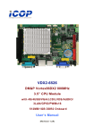
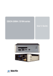
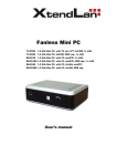
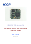
User’s Manual PPC-090T DMP Vortex86 DX2 Processor Compact Panel PC with 9” Touchscreen PPC-090T-D2N3N PPC-090T-D2N4N PPC-090T-D2N3N-GE PPC-090T-D2N4N-GE PPC-090T-D2W4N PPC-090T-D2W4N-GE (Revision 1.2A) PPC-090T User’s Manual IUMPPC090T-01 Ver.1.2A Sep, 2015 i REVISION DATE VERSION DESCRIPTION 2014/1/22 Version 1.0A New Release 2014/3/11 Version 1.1A Add 4.3 Serial Ports Setting (RS232/422/485) 2015/9/15 Version 1.2A Change the SPEC of Section 3.1 PPC-090T User’s Manual IUMPPC090T-01 Ver.1.2A Sep, 2015 ii COPYRIGHT The information in this manual is subject to change without notice for continuous improvement in the product. All rights are reserved. The manufacturer assumes no responsibility for any inaccuracies that may be contained in this document, and makes no commitment to update or to keep current the information contained in this manual. No part of this manual may be reproduced, copied, translated or transmitted, in whole or in part, in any form or by any means without the prior written permission of the ICOP Technology Inc. Copyright 2015 ICOP Technology Inc. Manual # IUMPPC090T-01 Ver.1.2A Sep, 2015 TRADEMARKS ACKNOWLEDGMENT Vortex86DX2 is the registered trademark of DMP Electronics Inc. Other brand names or product names appearing in this document are the properties and registered trademarks of their respective owners. All names mentioned herewith are served for identification purpose only. For more detailed information or if you are interested in other ICOP products, please visit our official websites at: Global: www.icop.com.tw USA: www.icoptech.com Japan: www.icop.co.jp BV: www.icoptech.eu China: www.icop.com.cn For technical support or demo images of operating systems download, please visit our websites at: ICOP Technical Resource: http://tech.icop.com.tw/ Software Support: http://www.icoptech.net/ This Manual is for the PPC-090T. PPC-090T User’s Manual IUMPPC090T-01 Ver.1.2A Sep, 2015 i SAFETY INFORMATION Read these Safety instructions carefully. Please carry the unit with both hands, handle carefully. Make sure the voltage of the power source is correct before connecting the equipment to the power outlet. Do not expose your Panel PC to rain or moisture in order to prevent shock and fire hazard. Input voltage rated +12 ~ 24 VDC Operating temperature between 0~+50°C (+32~+122°F). Keep PPC-090T away from humidity. When a Compact Flash Card or a SATA Slim is the main operating system storage, please turn off power before inserting or removing. Do not open the cabinet to avoid electrical shock. Refer to your nearest dealer for qualified personnel servicing. Never touch un-insulated terminals or wire unless your power adaptor is disconnected. Locate your Panel PC as close as possible to the socket outline for easy access and to avoid force caused by entangling of your arms with surrounding cables from the Panel PC. USB connectors are not supplied with Limited Power Sources. If the equipment is not used for a long time, disconnect it from the power source to avoid damage by transient overvoltage. WARNING! DONOTATTEMPTTOOPENORTODISASSEMBLETHECHASSIS (ENCASING)OFTHISPRODUCT.PLEASECONTACTYOURDEALER FORSERVICINGFROMQUALIFIEDTECHNICIAN. PPC-090T User’s Manual IUMPPC090T-01 Ver.1.2A Sep, 2015 ii Content Content ....................................................................................................... iii Ch. 1 General Information ............................................................................1 1.1 Product Description ............................................................................2 1.2 Product Specifications.........................................................................3 1.3 Inspection standard for TFT-LCD Panel..............................................5 1.4 Product Dimensions............................................................................8 1.5 Panel Mounting Instruction ...............................................................10 1.6 Ordering Information .........................................................................12 Ch. 2 System Installation............................................................................13 2.1 CPU Board Outline ...........................................................................14 2.2 Connector Summary .........................................................................15 2.3 Connector Pin Assignments..............................................................16 2.4 External I/O Overview .......................................................................18 2.5 External I/O Pin Assignment .............................................................19 2.6 Watchdog Timer................................................................................20 Ch. 3 Hardware Installation ........................................................................21 3.1 Installing the SATA Slim ....................................................................22 3.2 Installing the Compact Flash.............................................................24 Ch. 4 Driver Installation ..............................................................................25 4.1 PPC-090T Development Note ..........................................................27 4.2 BIOS Default Setting.........................................................................28 4.3 Serial Ports Setting (RS232/422/485) ...............................................29 Warranty.....................................................................................................32 PPC-090T User’s Manual IUMPPC090T-01 Ver.1.2A Sep, 2015 iii Ch. 1 General Information 1.1 Product Description 1.2 Product Specifications 1.3 Inspection standard for TFT-LCD Panel 1.4 Product Dimensions 1.5 Mounting Instruction 1.6 Ordering Information PPC-090T User’s Manual IUMPPC090T-01 Ver.1.2A Sep, 2015 1 1.1 Product Description ICOP Technology Inc. is proudly going to release a brand new Panel PC, which offers fanless design, low power consumption, and IP65 front panel. The PPC-090T is powered by DMP’s latest Vortex86DX2 SoC, the 3rd generation SoC of Vortex86 family, and dual-channel 1GB DDRII chipset that handles processing more efficiently and provides faster performance. The resistive touch panel with LED backlight TFT LCD increases operation convenience and visibility in outdoor environments. The ultra-compact and thin exterior design is perfect for the present demanding embedded and productive applications. The new PPC-090T inherited PDX/PMX-series’ smooth appearance and ultra-texture aluminum exterior design to make your industrial applications look more stylish. The versatile I/O ports, IP65 front panel, 10/100Mps Ethernet, GIGA high-speed Ethernet, WiFi, etc. can fulfill fundamental functions. Our consistent advantages feature stable performance, extended working temperature support, low power consumption and fanless design. The expandable customize I/O ports can be accommodated connectivity requirements to industrial machine platforms and industrial automation equipment’s needs. The PPC-090T supports Windows Embedded CE, Windows Embedded Standard 2009, Windows Embedded Compact 7, and Linux to meet ready-to-market demand and provide competitive advantages for customers. PPC-090T User’s Manual IUMPPC090T-01 Ver.1.2A Sep, 2015 2 1.2 Product Specifications CPU BOARD SPECIFICATIONS CPU DM&P Vortex86DX2 933MHz Cache L1:16KB I-Cache, 16KB D-Cache L2: 256KB Cache BIOS AMI BIOS Memory 512MB / 1GB DDR2 onboard Watchdog Timer Software Programmable from 30.5u to 512 seconds x 2 sets LAN Integrated 10/100M Ethernet X1 Giga Ethernet (Optional) X1 Audio HD Audio-Realtek ALC262 CODEC Compact Flash Type I / II Slot, Internal Drives SATA SLIM SD Slot (Optional) I/O RS-232/422/485 x 2 USB Ports (Ver2.0) x 3 PS/2 KB Audio-Out RJ-45 Port x 1 GIGA Ethernet Port X 1 (Optional) MECHANICAL & ENVIRONMENT Power Requirement +12 ~ 24VDC Power Consumption +24VDC@ 1A Operating Temperature 0~+50°C (+32~+122°F) / -20~+60°C (-4~+140°F) PPC-090T User’s Manual IUMPPC090T-01 Ver.1.2A Sep, 2015 3 Storage Temperature -30~+70°C (-22~ +158°F) Operating Humidity 0% ~ 90% Relative Humidity, Non-Condensing Dimensions 242x156.5x44mm (9.68"x6.26"x1.76") Weight 3.0 Kg Protection IP65 Front Panel Certification CE / FCC / VCCI / Vibration LCD SPECIFICATIONS Display Type 9” WSVGA TFT LCD Backlight Unit LED Display Resolution 1024(W) x 600(H) Brightness (cd/m2) 300 nits Contrast Ratio 500 : 1 Display Color 262,144 Pixel Pitch (mm) 190.5 (H) x 189 (V) Viewing Angle Vertical 140o, Horizontal 160o Backlight Lifetime 25,000 hrs TOUCHSCREEN Type Analog Resistive Resolution Continuous Transmittance 80% Controller PS/2 interface Software Driver Linux / WinCE / Windows XP Durability 1 million PPC-090T User’s Manual IUMPPC090T-01 Ver.1.2A Sep, 2015 4 1.3 Inspection standard for TFT-LCD Panel DEFECT TYPE Not LIMIT SPOT e φ<0.15mm Ignore 0.15mm≦φ≦0.5mm N≦4 Note 1 0.5mm<φ N=0 0.03mm<W≦0.1mm, L≦5mm N≦3 Note 1.0mm<W, 1.5mm<L N=0 1 φ<0.15mm Ignore 0.15mm≦φ≦0.5mm N≦2 FIBER VISUAL INTERNAL DEFECT POLARIZER Note BUBBLE 1 0.5mm<φ Mura N=0 It’ OK if mura is slight visible through 6%ND filter A Grade B Grade Note C Area O Area Total C Area O Area Total BRIGHT DOT 3 Note N≦0 N≦2 N≦2 N≦2 N≦3 N≦5 2 ELECTRI DARK DOT N≦2 N≦3 N≦3 N≦3 N≦5 N≦8 N≦5 N≦6 N≦8 CAL DEFECT Note TOTAL DOT N≦4 2 TWO ADJACENT DOT N≦1 N≦1 N≦1 N≦1 N≦1 Note pair pair pair pair pair 4 N≦0 THREE OR MORE NOT ALLOWED ADJACENT DOT LINE DEFECT NOT ALLOWED (1) One pixel consists of 3 sub-pixels, including R, G, and B dot. (Sub-pixel = Dot) (2) Little bright Dot acceptitable under 6% ND-Filter. (3) If require G0 grand (Total dot N≦0), please contact region sales. PPC-090T User’s Manual IUMPPC090T-01 Ver.1.2A Sep, 2015 5 [ Note 1 ] W: Width[mm]; L: Length[mm]; N: Number; φ: Average Diameter. (a) White / Black Spot (b) Polarizer Bubble [ Note 2 ] Bright dot is defined through 6% transmission ND Filter as following. [ Note 3 ] Display area C Area: Center of display area O Area: Outer of display area [ Note 4 ] Judge the defect dot and the adjacent dot as following. Allow below (as A, B, C and D status) adjacent defect dots, including bright and dark adjacent dot. And they will be counted 2 defect dots in total quantity. PPC-090T User’s Manual IUMPPC090T-01 Ver.1.2A Sep, 2015 6 The defects that are not defined above and considered to be problem shall be reviewed and discussed by both parties. Defects on the Black Matrix, out of Display area, are not considered as a defect or counted. PPC-090T User’s Manual IUMPPC090T-01 Ver.1.2A Sep, 2015 7 1.4 Product Dimensions PPC-090T User’s Manual IUMPPC090T-01 Ver.1.2A Sep, 2015 8 PPC-090T User’s Manual IUMPPC090T-01 Ver.1.2A Sep, 2015 9 1.5 Panel Mounting Instruction 1. Cut a mounting hole in the panel. (Refer to PPC090T Dimensions on page 11~12.) (Note 1) 2. Check and remove the twelve M3 screws in a diagonal pattern as image below if necessary. 3. Place PPC090T facedown on a clean, flat surface. 4. Slide the panel cutout around the back of PPC090T, until the panel rests directly on the gasket. Make sure the screw holes align with the screw holes on PPC090T. 5. The screw size is M3*L (L=wall thickness + 6.0mm) (Note 2) 6. Insert all twelve M3 screws into the screw holes. (Note 2) 7. Finger-tighten the M3 screws. Finish tightening the M3 screws in a diagonal pattern using an M3 screw driver (see the image as below); maximum torque 1.18Nm (12 kgfcm). PPC-090T User’s Manual IUMPPC090T-01 Ver.1.2A Sep, 2015 10 Note 1: It is strongly recommended that a professional machine shop cut the mounting hole in the panel. Note 2: The length for all twelve M3 screws will be according to the thickness of mounting panel. For example: The length of standard M3 screws for PPC-090T is 6mm. If the thickness of your mounting panel is 3mm and washer thickness is 1mm, you have to use 10mm M3 screw. PPC-090T User’s Manual IUMPPC090T-01 Ver.1.2A Sep, 2015 11 1.6 Ordering Information PART NUMBER DESCRIPTION PPC-090T-D2N 9” Panel PC w/1GB Mem ory 3USB/AUDIO/LAN/2COM/DC12~24V PPC-090T-D2N-GE 9” Panel PC w/1GB Memory 3USB/AUDIO/LAN/GIGA LAN/2COM/ DC12~24V PPC-090T-D2W 9” Panel PC w/1GB Memory 3USB/AUDIO/LAN/2COM/DC12~24V/ Wide Temp PPC-090T-D2W-GE 9” Panel PC w/1GB Memory 3USB/AUDIO/LAN/GIGA LAN/2COM/ DC12~24V/Wide Temp PACKING LIST PART NUMBER PACKAGE PPC-090T-D2N PPC-090T-D2N *1 M4 L8 Screw *4 PPC-090T-D2N-GE PPC-090T-D2N-GE *1 M4 L8 Screw *4 PPC-090T-D2W PPC-090T-D2W *1 M4 L8 Screw *4 PPC-090T-D2W-GE PPC-090T-D2W-GE *1 M4 L8 Screw *4 PPC-090T User’s Manual IUMPPC090T-01 Ver.1.2A Sep, 2015 12 Ch. 2 System Installation 2.1 CPU Board Outline 2.2 Connector Summary 2.3 Connector Pin Assignments 2.4 External I/O Overview 2.5 External I/O Pin Assignment 2.6 Watchdog Timer PPC-090T User’s Manual IUMPPC090T-01 Ver.1.2A Sep, 2015 13 2.1 CPU Board Outline PPC CPU Board PPC-090T User’s Manual IUMPPC090T-01 Ver.1.2A Sep, 2015 14 2.2 Connector Summary No. Description Type of Connections Pin # J1 Power Terminal Connector External Power Plug 3-pin J3 COM (RS232/422/485) External D-Sub Male Connector 9-pin J4 USB External USB Connector 6-pin J5 USB External USB Connector 6-pin J6 PS/2Keyboard External Mini DIN Socket 6-pin J7 USB External USB Connector 6-pin J8 USB (Wi-Fi Optional) Internal USB Connector 5-pin J11 Ethernet External RJ45 Connector 8-pin J12 GIGA Ethernet External RJ45 Connector 8-pin J14 RS-232-422-485 2.0mm 10-pin box header 10-pin J16 SD Card Slot (Optional) Internal SD Card Socket J19 RS-232-422-485 (VGA) 2.0mm 10-pin box header J25 SATA Slim Slot Internal SATA Slim Socket J30 Audio Line-Out 1.25mm Phone Jack 2-pin J33 GPIO-X3 PH2*25F(2.0)-7.5mm/P2N71-2XX 50-pin J34 GPIO-X1 PH2*25F(2.0)-7.5mm/P2N71-2XX 50-pin J35 GPIO-X4 PH2*15F(2.0)-7.5mm/P2N71-2XX 30-pin J36 GPIO-X2 PH2*25F(2.0)-7.5mm/P2N71-2XX 50-pin CF1 CF Card Socket CF Type I/II Socket PPC-090T User’s Manual IUMPPC090T-01 Ver.1.2A Sep, 2015 10-pin 15 2.3 Connector Pin Assignments J7: USB J1: Power Terminal Connector Pin # Signal Name 1 +12~24V 2 GND 3 FG Pin # Signal Name Pin # Signal Name 1 VCC 2 USBD4- 3 USBD4+ 4 GND 5 GND 6 GND J8: USB (Wi-Fi Optional) J3: COM (RS232/422/485) Pin # 1 Signal Name DCD1/422TX-/ RS485- Pin # 2 Signal Name RXD1/422TX+ /RS485+ 3 TXD1/422RX+ 4 DTR1/422RX- 5 GND 6 DSR1 7 RTS1 8 CTS1 9 RI1 J4: USB Pin # Signal Name Pin # Signal Name 1 VCC 2 USBD2- 3 USBD2+ 4 GND 5 GND 6 GND J5: USB Pin # Signal Name Pin # Signal Name 1 VCC 2 USBD3- 3 USBD3+ 4 GND 5 GND 6 GND PPC-090T User’s Manual Pin # Signal Name Pin # Signal Name 1 VCC 2 USBD1- 3 USBD1+ 4 GND 5 GND J6 : PS/2Keyboard Pin # Signal Name Pin # Signal Name 1 KBCLK 2 MSCLK 3 GND 4 KBDATA 5 MSDATA 6 VCC 7 GND 8 GND 9 GND J19: RS-232-422-485 Pin # Signal Name Pin # Signal Name 1 R OUT 2 GND 3 G OUT 4 GND 5 B OUT 6 GND 7 HSYNC 8 GND 9 VSYNCD 10 GND IUMPPC090T-01 Ver.1.2A Sep, 2015 16 J33/J34/J35/J36: GPIO 180-pin J33 J34 Signal Pin# Signal Pin# Name J35 Signal Pin# Name Signal Pin# Name J36 Signal Pin# Name Signal Pin# Name Signal Pin# Name Signal Pin# Name Name 1 GND 2 GND 1 GND 2 SBHE 1 VCC 2 VCC 1 SA7 2 SA6 3 GP34 4 GP35 3 RSTDRV 4 SD7 3 GND 4 GND 3 IRQ3 4 SA5 5 GP36 6 GP37 5 VCC 6 SD6 5 GP90 6 GP91 5 IRQ10 6 SA4 7 GP40 8 GP41 7 SD8 8 SD5 7 GP92 8 GP93 7 IRQ11 8 SA3 9 GP42 10 GP43 9 SD9 10 SD4 9 GP94 10 GP95 9 IRQ12 10 SA2 11 GP44 12 GP45 11 SD10 12 SD3 11 GP96 12 GP97 11 BALE 12 SA1 13 GP46 14 GP47 13 SD11 14 SD2 13 GPCS0 14 GPCS1 13 OSC 14 SA0 15 GP50 16 GP51 15 SD12 16 SD1 15 GP00 16 GP01 15 GND 16 IQ14 17 GP52 18 GP53 17 SD13 18 SD0 17 GP02 18 GP03 17 GP10 18 GND 19 GP54 20 GP55 19 GND 20 GND 19 GP04 20 GP05 19 GP12 20 GP11 21 GP56 22 GP57 21 SMEMW 22 IOCHRDY 21 GP06 22 GP07 21 GP14 22 GP13 23 GND 24 GND 23 SMEMR 24 AEN 23 RS485+1 24 RS485-1 23 GP16 24 GP15 25 GP60 26 GP61 25 IOW 26 SA19 25 VBATT 26 FGND 25 GP20 26 GP17 27 GP62 28 GP63 27 IOR 28 SA18 27 VIN 28 VIN- 27 GP22 28 GP21 29 GP34 30 GP65 29 SD14 30 SA17 29 VIN 30 VIN- 29 GP24 30 GP23 31 GP66 32 GP57 31 SD15 32 SA16 31 GP26 32 GP25 33 GP70 34 GP71 33 MEMCS16 34 SA15 33 GP30 34 GP27 35 GP72 36 GP73 35 IOCS16 36 SA14 35 GP32 36 GP31 37 GP74 38 GP75 37 REFRESH 38 SA13 37 XPCIRST- 38 GP33 39 GP76 40 GP77 39 40 SA12 39 GND 41 GP80 42 GP81 41 SYSCLK 42 SA11 41 XPE0_RX- 42 XPE0_TX- 43 GP82 44 GP83 43 IRQ7 44 SA10 43 XPE0_RX+ 44 XPE0_TX+ 45 GP84 46 GP85 45 IRQ6 46 SA9 45 47 GP86 48 GP87 47 IRQ5 48 SA8 47 XYPE0_CLK- 48 XUSBD3- 49 GND 50 GND 49 IRQ4 50 GND 49 XYPE0_CLK+ 50 XUSBD3+ PPC-090T User’s Manual GND IUMPPC090T-01 Ver.1.2A Sep, 2015 GND GND 40 46 GND 17 2.4 External I/O Overview Power Switch PS/2 KB +12 ~ 24VDC RS-232/422/485 USB 2.0 PORT Audio-Out 10/100Mbps GIGA Ethernet Ethernet (Optional) NOTE 1. GIGA LAN, Wireless are optional 2. RS232/422/485 is selected by BIOS setting PPC-090T User’s Manual IUMPPC090T-01 Ver.1.2A Sep, 2015 18 2.5 External I/O Pin Assignment Power Switch J4/J5/J7: USB Pin # Status | ON Pin # Signal Name O OFF 1 VCC 2 USB0- 3 USB0+ Power Connector DC-IN 24V Pin # Signal Name 4 GND 1 +12~24V 5 GGND 2 GND 6 GGND 3 FG RJ45 PS/2 Keyboard Pin Signal Pin Signal Pin # Signal Name # Name # Name 1 KBCLK 1 FTXD+ 2 FTXD- 2 PMCLK 3 FRXIN+ 4 NC 3 GND 5 NC 6 FRXIN- 4 KBDAT 7 NC 8 NC 5 PMDAT 6 SB5V GIGA Ethernet (Optional) Pin Signal Pin Signal J3: COM-RS232/422/485 # Name # Name (Change setting by BIOS) 1 FTXD+ 2 FTXD- 3 FRXIN+ 4 NC 5 NC 6 FRXIN- 7 NC 8 NC Pi n # Signal Name Pi n # DCD1/422 1 TX-/RS48 TXD1 / 422RX+ Name RXD1/422 2 53 Signal 4 TX+/RS48 Audio Line-Out 5+ Pin # Signal Name DTR1 / 1 GND 422RX- 2 LOUTL 5 GND 6 DSR1 3 Open Touch 7 RTS1 8 CTS1 4 Open Touch 9 RI1 5 VREFOUT PPC-090T User’s Manual IUMPPC090T-01 Ver.1.2A Sep, 2015 19 2.6 Watchdog Timer There are two watchdog timers in PPC-090T, we also provide DOS, Linux and WinCE example for your reference. For more technical support, please visit: http://tech.icop.com.tw or download the PDF file: dmp.com.tw/tech PPC-090T User’s Manual IUMPPC090T-01 Ver.1.2A Sep, 2015 20 Ch. 3 Hardware Installation PPC-090T supports various kinds of storages for industrial application, divided into SATA Slim, CompactFlash or SD card (optional). 3.1 Installing the SATA Slim 3.2 Installing the Compact Flash PPC-090T User’s Manual IUMPPC090T-01 Ver.1.2A Sep, 2015 21 3.1 Installing the SATA Slim [SPEC] JEDEC SFF-8156 standard form factor 53 x 32 x 4.0 mm SDM-SST-SLIM(M)4G SDM-SST-SLIM(M)8G SDM-SST-SLIM(M)16G SDM-SST-SLIM(M)32G [STEP] 1. Remove the nine screws in a diagonal pattern as the image below. 2. Place the SATA slim horizontally aligned and gently put into the socket until you feel a click. PPC-090T User’s Manual IUMPPC090T-01 Ver.1.2A Sep, 2015 22 3. Insert all nine screws into the screw holes. PPC-090T User’s Manual IUMPPC090T-01 Ver.1.2A Sep, 2015 23 3.2 Installing the Compact Flash [STEP] 1. Remove the nine screws in a diagonal pattern as the image below. 2. Gently insert the CF card along the track. Caution: Please watch out for the direction which the CF card has to be face up. 3. Insert all nine screws into the screw holes. PPC-090T User’s Manual IUMPPC090T-01 Ver.1.2A Sep, 2015 24 Ch. 4 Driver Installation 4.1 PPC-090T Development Note 4.2 BIOS Default Setting 4.3 Serial Ports Setting (RS232/RS422/RS485) PPC-090T User’s Manual IUMPPC090T-01 Ver.1.2A Sep, 2015 25 VGA The Vortex86DX2 processor is integrated RDC Display chip which is an ultra-low powered graphics chipset with total power consumption at around 1-1.5 W. LAN The Vortex86DX2 processor is integrated 10/100Mbps Ethernet controller that supports both 10/100BASE-T and allows direct connection to your 10/100Mbps Ethernet based Local Area Network for full interaction with local servers, wide area networks such as the Internet. I/O and IRQ settings can be done by software with the supplied utility software, or it can be set for Plug and Play compatibility. The controller supports: Half / Full-Duplex Ethernet function to double channel bandwidth, auto media detection. AUDIO The ALC262 series are 4-Channel High Definition Audio Codecs with UAA (Universal Audio Architecture) featuring two 24-bit stereo DACs and three 20-bit stereo ADCs, they are designed for high performance multimedia desktop and laptop systems. The ALC262 series incorporates proprietary converter technology to achieve over 100dB Signal-to-Noise ratio playback quality; easily meeting PC2001 requirements and also bringing PC sound quality closer to consumer electronic devices. OPERATING SYSTEM SUPPORT The PPC-090T provides the VGA and LAN drivers for Linux, Windows CE, Windows XP Professional, and Windows Embedded standard (XPE). (Linux can use with Compact Flash card only.) Please get the drivers from ICOP technical support URL: tech.icop.com.tw PPC-090T also supports most of the popular Linux distributions, for more detail information, please visit DMP official website: vortex86dx2 PPC-090T User’s Manual IUMPPC090T-01 Ver.1.2A Sep, 2015 26 4.1 PPC-090T Development Note < WINDOWS DEVELOPMENT GUIDE > Windows Embedded CE 6.0 BSP, Windows Embedded Compact 7 BSP, and Windows Embedded Standard 2009 trial image with development notes, please visit technical website to get more information at http://tech.icop.com.tw/. < LINUX INSTALLATION NOTE> Please visit Linux technical website to get more information at ftp://ftp.dmp.com.tw/Linux_DEMO/Vortex86_Linux_Support_List_revised. htm. PPC-090T User’s Manual IUMPPC090T-01 Ver.1.2A Sep, 2015 27 4.2 BIOS Default Setting If the system cannot be booted after BIOS changes are made, Please follow below procedures in order to restore the CMOS as default setting. Press < End > Key, when the power on Press < Del > to enter the AMI BIOS setup Press < F9 > to Load Optimized defaults Press < F10 > to Save configuration changes and exit setup PPC-090T User’s Manual IUMPPC090T-01 Ver.1.2A Sep, 2015 28 4.3 Serial Ports Setting (RS232/422/485) Please press <Del> to get into the BIOS settings after booting the machine, and follow the steps below: [Step 1] Use the arrow key to select the category “Chipset” on the top of the menu, then select SouthBridge Configuration in the sub menu and press <Enter> [Step 2] Use the arrow key to select “TXDEN Serial Port Type Configuration” and press <ENTER> PPC-090T User’s Manual IUMPPC090T-01 Ver.1.2A Sep, 2015 29 [Step 3] Choose the port you would like to change. For example, choose TXDEN1 for COM1 and press <Enter>. You will then see three options; select the desired type and press <Enter> to finish the setting. The Serial Ports setting is finished PPC-090T User’s Manual IUMPPC090T-01 Ver.1.2A Sep, 2015 30 [Step 4] Press <Esc> twice to get back to the Top Menu. Use the arrow key to the category “Exit”, and select the option “Save Changes and Exit”. Press <Enter> and choose [OK] to keep your changes, then the device will reboot automatically. PPC-090T User’s Manual IUMPPC090T-01 Ver.1.2A Sep, 2015 31 Warranty This product is warranted to be in good working order for a period of one year from the date of purchase. Should this product fail to be in good working order at any time during this period, we will, at our option, replace or repair it at no additional charge except as set forth in the following terms. This warranty does not apply to products damaged by misuse, modifications, accident or disaster. Vendor assumes no liability for any damages, lost profits, lost savings or any other incidental or consequential damage resulting from the use, misuse of, originality to use this product. Vendor will not be liable for any claim made by any other related party. Return authorization must be obtained from the vendor before returned merchandise will be accepted. Authorization can be obtained by calling or faxing the vendor and requesting a Return Merchandise Authorization (RMA) number. Returned goods should always be accompanied by a clear problem description. All Trademarks appearing in this manuscript are registered trademark of their respective owners. All Specifications are subject to change without notice. ©ICOP Technology Inc. 2015 PPC-090T User’s Manual IUMPPC090T-01 Ver.1.2A Sep, 2015 32