1
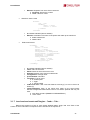
ENERGY MANAGEMENT SOFTWARE
POWERSTUDIO
(Standard, SCADA, Deluxe)
Version 4.0
USER MANUAL 1 / 4
(M98232301-03-13A)
PowerStudio
2
PowerStudio
User Manual
PowerStudio
DISCLAIMER
CIRCUTOR, SA reserves the right to make modifications to the device or the unit
specifications set out in this instruction manual without prior notice.
CIRCUTOR, SA, on its web site, supplies its customers with the latest versions of the
device specifications and the most updated manuals.
www.circutor.com
User Manual
3
PowerStudio
PowerStudio
CONTENTS
DISCLAIMER ....................................................................................................................................................... 3
CONTENTS ........................................................................................................................................................... 4
LOG OF REVISIONS .......................................................................................................................................... 6
1.- GENERAL DESCRIPTION ........................................................................................................................... 7
1.1.- POWERSTUDIO TOPOLOGIES............................................................................................................... 7
1.1.1
All in one ......................................................................................................................................... 7
1.1.2
Engine/editor and clients ................................................................................................................ 7
1.1.3
Engine/editor and clients ................................................................................................................ 8
1.1.4
Engine, editors and clients .............................................................................................................. 8
1.2.- POWERSTUDIO INSTALLATION .......................................................................................................... 9
1.3.- TYPICAL APPLICATION ...................................................................................................................... 14
1.3.1
Configure the communications engine .......................................................................................... 14
1.3.2
Create the application in the editor .............................................................................................. 15
1.3.3
Export the application to the engine ............................................................................................. 16
1.3.4
View the application in the client .................................................................................................. 18
2.- SYSTEM REQUIREMENTS ....................................................................................................................... 21
3.- APPENDICES ................................................................................................................................................ 22
3.1.- XML SERVICES ......................................................................................................................................... 22
3.1.1
services / user / devices.xml .......................................................................................................... 22
3.1.2
services/user/deviceInfo.xml?id=device?... ................................................................................... 22
3.1.3
services/user/varInfo.xml?var=device.variable?...?id=device?... ................................................ 23
3.1.4
services/user/values.xml?var=device.variable?...?id=device?... .................................................. 24
3.1.5
services / user / forceVariables.xml? id = device .......................................................................... 25
3.1.6
services/user/records.xml?begin=…?end=…?var=…?period=900............................................. 25
3.1.7
services/user/events.xml?begin=…?end=…?id=… ...................................................................... 27
3.1.8
services/user/recordsEve.xml?begin=…?end=…?id=… .............................................................. 28
3.2.- F.A.Q ........................................................................................................................................................ 30
3.2.1
Some equipment is not communicating. What could be happening? ............................................ 30
3.2.2
A TCP2RS converter does not communicate. What could be happening? ................................... 30
3.2.3
I cannot see the applet. What could be happening? ...................................................................... 30
3.2.4
The Applet does not display the texts properly. What could be happening? ................................. 30
3.2.5
The values display is not what I expected. What could be happening?......................................... 30
3.2.6
An event is not behaving as expected. What could be happening? ............................................... 31
3.2.7
I can’t paint the graph correctly. What could be happening? ...................................................... 31
3.2.8
The Paint Pot is not working correctly. What could be happening? ............................................. 31
3.2.9
The software is not sending e-mails. What might be happening? ................................................. 32
3.2.10 Can I launch external applications from applet? .......................................................................... 32
3.2.11 How can I see the applet from a machine which is not running Windows? .................................. 32
3.2.12 Can I directly connect with a known IP when I execute the Applet? What happens if there’s
authentication? What parameters can I use to configure the Applet application launch? ........................... 32
3.2.13 I am making my first screen or report and I cannot add a background image or a still picture.
What is happening?....................................................................................................................................... 33
3.2.14 What can be "counted"? ................................................................................................................ 33
3.2.15 I would like to export the report data in order to process it later. How can I do it? .................... 33
3.2.16 I tried to make a table with the client application and I get the Message "Table too Big." What
can I do to see it? .......................................................................................................................................... 35
3.2.17 How can I simulate a control switch? ........................................................................................... 36
3.2.18 How do I add animation to the SCADA? ...................................................................................... 36
3.2.19 How can I simulate a level control?.............................................................................................. 37
3.2.20 How can I change the properties of control in accordance with a condition? ............................. 37
3.2.21 How can I know the status of a device? ........................................................................................ 38
3.2.22 How can I display documents from a SCADA screen? ................................................................. 38
4
User Manual
PowerStudio
3.2.23 How can I obtain an event according to the status of a device? ................................................... 38
3.2.24 How can I produce sounds in response to an event? .................................................................... 38
3.2.25 How do I show documents in response to an event? ..................................................................... 39
3.2.26 How can I communicate with a TCP2RS+ converter by way of a router? ................................... 39
3.2.27 There are screens on which I cannot see the text of the controls properly or they are truncated.
How can I solve this? .................................................................................................................................... 39
3.2.28 When viewing a graph and selecting the tooltip, the graph disappears. How can I solve this? ... 40
3.2.29 I cannot connect with the engine or some TCP/IP devices has errors. On the Java console I see:
java.net.BindException: Address already in use: connect. How can I solve this?........................................ 40
3.2.30 When I run the client as an embedded applet in the webpage within a browser, how can I access
as an anonymous user? ................................................................................................................................. 40
3.2.31 I’m not able to create SCADA screens or reports or define events ¿Where’s the problem?......... 40
4.- MAINTENANCE AND TECHNICAL SERVICE ...................................................................................... 41
5.- GUARANTEE ................................................................................................................................................ 41
User Manual
5
PowerStudio
PowerStudio
LOG OF REVISIONS
Date
11/13
6
Revision
M98232301-03-13A
Description
Original version
User Manual
PowerStudio
1.- GENERAL DESCRIPTION
PowerStudio is an energy management software package and its main features are the
configuration, communication and monitoring of devices and the creation of SCADA screens and
reports. It also has a set of tools such as events, filters, calculated variables, and an images and styles
manager to facilitate the user's interaction.
In its version 4.0, PowerStudio is divided into three main modules, the applications editor, the
communications engine and the client.
The editor is the module that is in charge of applications management and it allows a new
application to be created, to modify an existing application, to import an application from the engine or
to export an application to the engine.
The engine is the module in charge of running the application it receives from the editor, and of
communicating with the different devices, storing downloads and attending to the various requests
made by both the editor and the client.
The client is the module that allows connection with an engine and access to the SCADA
screens, reports and to view the instantaneous values recorded by the devices. Graphs and listings
can also be prepared of the recorded values, events can be viewed, the status of the devices can be
displayed, etc.
1.1.- POWERSTUDIO TOPOLOGIES
PowerStudio's software design as three well-differentiated modules: the editor, the engine and
the client, make it possible to use it through different topologies, which are explained in detail below:
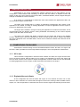
1.1.1 All in one
This is the basic configuration in which the three modules, the editor, the engine and the client,
are on the same machine. With the editor we can create a new application to send to the engine and
from the client connect to the engine to display the application. From the editor we can also download
an existing application from the engine, modify it and then send it back to the engine.
1.1.2 Engine/editor and clients
In this configuration we have the editor and engine on one machine and from one or more
clients on other machines we connect with the engine to access the viewing of data, SCADA screens,
reports, etc. This configuration is useful when we want to view the engine data remotely from the client.
User Manual
7
PowerStudio
PowerStudio
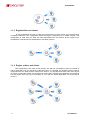
1.1.3 Engine/editor and clients
In this configuration we have an editor, an engine and one or more clients, each of these being
on different machines. This configuration allows the engine configuration to be edited remotely. This
configuration is used when we want the data downloaded from the devices by the engine to be
centralized in a machine that is independent of the editor machine.
1.1.4 Engine, editors and clients
This configuration is the same as the previous one with the only difference that it is possible to
edit an application from two machines at the same time. For example, the SCADA screens could be
configured from one editor and the reports from another. It is important that each editor must import
the engine configuration before new changes are made. When modifying the application and exporting
it to the engine, were any type of incongruity to occur with the engine application, we will be able to
correct it.
8
User Manual
PowerStudio
1.2.- POWERSTUDIO INSTALLATION
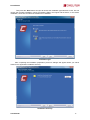
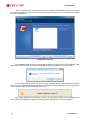
Once it has been ascertained that your machine meets the minimum requirements for the
software insert the PowerStudio CD and select the install software option that will appear on the main
screen. If the main screen does not appear automatically when the CD is inserted in the unit, you must
manually run (from Windows explorer or with the “Run” option on the START menu) the
“AUTORUN.EXE” program which is in the CD's root directory.
Installation language
After selecting the installation language and pressing the “Next” button we will access the
license screen where we must accept the terms to be able to continue.
User Manual
9
PowerStudio
PowerStudio
License terms
Then press the “Next” button where you will be required to register the product and enter the
user name, the company name and software serial number.
Register screen
10
User Manual
PowerStudio
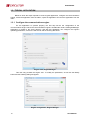
Then press the “Next” button and you will access the installation type selection screen. We can
choose the complete installation, which will install the Editor, the Engine and the Client, or the custom
installation, where we can select the modules to be installed.
Installation type
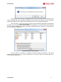
After completing the installation preparation process a dialogue will appear where you will be
asked for the application installation directory.
Installation directory
User Manual
11
PowerStudio
PowerStudio
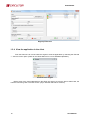
On the next screen we can select the module or modules to be installed. You must only select
the components that are required for the selected topology. (See section 1.1 PowerStudio topologies
for further explanation).
Components selection
If the installation detects that you have already installed a previous version of PowerStudio, it will
allow you to make a backup copy of the configuration before you update to the current version.
If you wish to make a backup copy, the ‘Backup’ directory will be created within the directory
where you are installing PowerStudio and the old configuration will be backed up. If you do not wish to
make a backup copy, the old configuration will be lost.
After having updated the configuration, if there is an old version installed and the installation has
been completed, a dialogue will appear reporting that the installation was correctly completed.
12
User Manual
PowerStudio
Installation complete
When the client is installed a default application will be created, called ‘Local’, which will be the
active installation the first time the client is run. If the PowerStudio installation is done on top of a
previous version, the entire configuration will become a part of the ‘Local’ application.
User Manual
13
PowerStudio
PowerStudio
1.3.- TYPICAL APPLICATION
Below we show the steps required to create a typical application, configure the communications
engine, create the application from the editor, export the application and view the application from the
client.
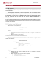
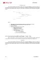
1.3.1 Configure the communications engine
For the application to operate properly, the first step will be the configuration of the
communications engine. When the communications engine is installed the runtime ‘PSEngineManager’
application is copied to the same directory, and with this application can configure the engine's
operating parameters, such as the web server and the working directories.
Engine view, Engine Manager
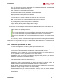
This view only provides the engine view. To modify the parameters, we will use the Modify
button and the following dialog will appear:
Engine configuration, Engine Manager
14
User Manual
PowerStudio
-
Port: We indicate the port that the engine will use to initialize the web server. The editor and
client requests will be attended to on this port.
-
User: User used if we desire edition authentication.
-
Password: We indicate the user password for edition authentication.
-
Repeat password: Re-enter password to validate it.
-
Timezone: Allows you to enter a different time zone from that of the system.
-
Data: Working directory for storing the data downloaded from the machines.
-
Cfg: Working directory to store the application's configuration.
-
Images: Working directory to store the application's images.
On the upper right-hand part of the screen, we will see an image indicating the engine status. The
possible statuses are the following:
-
The engine is not operating or not found.
The engine is active; there are no events or problems with the communications.
The engine is active; there are no events but there are problems with the communications.
The engine is active; there are problems with the communications and active events.
The engine is active; there are no problems with the communications but there are active
events.
It is necessary to start the communications engine so that the ‘Engine Manager’ can configure
the web server parameters. By default the communications engine attempts to start the web server on
port 80 and if it is busy, it seeks a free port, as we have seen, these parameters can subsequently be
changed with the ‘Engine Manager’.
1.3.2 Create the application in the editor
To create a new application, the following main steps must be performed:
-
Add and configure devices: Add first and second level devices and configure the
communications parameters. (Refer to the ‘Devices’ section in the ‘Editor manual’).
-
Create device groups: Organize the devices into groups according to the structure defined by
the user. (Refer to the ‘Device groups section in the ‘Editor manual’).
-
Create filters: Create one or more energy filters to apply to the data gathered by the devices.
(Refer to the ‘filters' section in the ‘Editor manual’).
-
Create calculated variables: Define new variables with values of different devices. (Refer to the
‘Calculated variables’ section in the ‘Editor manual’).
-
Create styles: Define styles configurations to apply to the fonts of the various controls of
SCADA screens and reports. (Refer to the ‘Styles’ section in the ‘Editor manual’).
-
Manage images: Add the images required for subsequent use in SCADA screens and reports.
(Refer to the ‘Images manager’ section in the ‘Editor manual’).
-
Create SCADA screens (only in SCADA and Deluxe versions): Create one or more SCADA
screens, which allow for visually displaying the application. (Refer to the ‘SCADA’ section in the
‘Editor manual’).
User Manual
15
PowerStudio
PowerStudio
-
Create reports (only in SCADA and Deluxe versions): Create one or more templates for
displaying reports. (Refer to the ‘Reports’ section in the ‘Editor manual’).
-
Create events (only in SCADA and Deluxe versions): Define application events, disabled
schedules, filters and their configuration. (Refer to the ‘Events’ section in the ‘Editor manual’).
-
Define user rights and authentication: Configure one or more profiles relating to the application
resources and assign to the users. (Refer to the ‘User authentication’ section in the ‘Editor
manual’).
-
Create device zones: Define the application zones, grouping the devices that we want to
display together in a screen. (Refer to ‘Zones’ section in the ‘Editor Manual’).
If we wish to modify the application in the communications engine, we first have to import it,
then modify it and export it to the engine so that the new changes are included.
1.3.3 Export the application to the engine
When we have completed an application or an existing one has been modified, we must export
it to the communications engine so that the latter takes all the changes made into account. While we
are editing an application, the communications engine continues to run the last application configured
in it and it is not until we export it from the client that these changes are implemented in the engine.
(Refer to the ‘Editor Manual’ for a more detailed explanation).
From the editor shortcut toolbar if we select the
application's export dialogue.
option, we will access the
Export application
In the export dialogue we must select the IP address and port of the engine to which we are
going to send the configuration, we will also mark the
option and enter the user and password if user authentication is enabled.
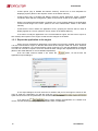
option, before sending the application it is verified to be
If we select the
correct, and the following message will be displayed if there is invalid data.
16
User Manual
PowerStudio
If we select the ‘No’ option the configuration will be sent to the engine with the detected errors
and it is possible that it will not operate as desired. If we select the ‘Yes’ option a screen will appear
reporting the detected errors. (Refer to the ‘Editor Manual’ for a more detailed explanation).
option, before sending the application an attempt will
If we select the
be made to communicate with the devices added in the application. If communication cannot be made
with any of them, a dialogue will appear reporting the detected incidents. (Refer to the ‘Editor Manual’
for a more detailed explanation).
Communication incidents report
From the editor it is possible to configure the default options that appear on the export
dialogue, we must go to the ‘File -> Engine preferences’ menu option. (Refer to the ‘Editor Manual’ for
a more detailed explanation).
User Manual
17
PowerStudio
PowerStudio
Engine preferences
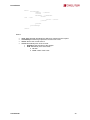
1.3.4 View the application in the client
From the Client we can connect with the engine to view the application by selecting the 'General
--> Connect' menu option. (Refer to the ‘Client Manual’ for a more detailed explanation).
Connect to the engine
Below some of the views obtained from the Client are shown, such as the device status view, the
machine monitoring view or SCADA screen (only in SCADA and Deluxe versions).
18
User Manual
PowerStudio
View device status by connection
User Manual
19
PowerStudio
PowerStudio
Device monitoring screen
Client application with a SCADA screen as an active view
20
User Manual
PowerStudio
2.- SYSTEM REQUIREMENTS
•
Microsoft Windows:
o 2003, 2008 and 2012 Server, XP Home, XP Profesional (Service Pack 1), Vista, Windows
7 and 8, 32 bits versions.
o 2003, 2008 and 2012 Server, XP Profesional (Service Pack 1), Vista, Windows 7 and 8, 64
bits versions.
•
Client over any operating system with Java Virtual Machine JRE 1.7.0 (Linux, Windows, etc.)
•
Host with i86 architecture (Intel, AMD, ...) for Engine and Editor, 1 GHz or more.
•
At least 1 GB of RAM.
•
1 GB free in HD (depending on the number and type of equipment connected space should be
increased at a rate of approximately 30 MB per device and year of data we want to save).
•
CD-ROM.
•
SVGA monitor with al least 1024x768 (1280x1024 or better recommended).
•
Windows compatible Mouse and keyboard.
For the software to work properly it will be necessary to install it as the Administrator, or
as a user with Administrator privileges.
User Manual
21
PowerStudio
PowerStudio
3.- APPENDICES
3.1.- XML Services
PowerStudio provides a range of XML services to enable, in some respects, communication
with other applications.
In requests where it is necessary to express a date and time, both in service request and the
data from the response, these will be represented in UTC (Universal Coordinated Time) with the format
DDMMYYYYHHMMSS (two digits for the day, two for the month, four for the year and two for the hour,
minutes and seconds. It is also possible to represent only a date as DDMMYYYY assuming that the
time is 00:00:00, or represent an hour as HHMMSS. Finally in cases where milliseconds are required
these are represented with three digits after the seconds, DDMMYYYYHHMMSSUUU or
HHMMSSUUU.
The requests must follow the URI standard (RFC 2396), so the user of these requests must
take into account this detail when making such calls (especially in cases where the name of any device
contains non-ASCII characters).It should also be taken into account that the length of the request may
not exceed 4000 characters.
3.1.1 / services / user / devices.xml
Returns the list of configured devices.
<devices>
<id> … </id>
…
</devices>
Where:
•
•
devices: Main field which will identify the main XML as a response to the device list
request.
id: Name of each one of the devices.
3.1.2 /services/user/deviceInfo.xml?id=device?...
Returns information on devices. Each of the devices on which information is required must be
included in the request as:
?id=device2?id=device2
<devices>
<device>
<id> … </id>
<description>… </ description>
<type>… </ type>
<typeDescription>… </ typeDescription>
<var>… </ var>
…
</device>
…
</devices>
Where:
•
•
22
devices: Main Field which will identify the XML as a response to the device
information request.
device: Information from each of the devices requested:
id: Name of the device.
description: Description of device
User Manual
PowerStudio
type: Type of device (for example CVM144)
typeDescription: A description of the type of device (for example: CVM-144)
var: Name of each of the variables of the device. The name will be expressed
as device.variable (Refer to the variable appendix in the ‘Devices Manual’).
3.1.3 /services/user/varInfo.xml?var=device.variable?...?id=device?...
Returns variable information when carrying out the XML request. Each of the variables from
which a value is desired should be included in the request as:
?var=device.variable
And if you want to get information from all the variables of a device this must be indicated as
?id=device
With it being possible to request information from one or more variables and one or more
devices in the same request.
<varInfo>
<var>
<id> … </id>
<title>… </ title>
<hasValue> T </ hasValue>
<hasLogger> T </ hasLogger>
<sampleMode>… </ sampleMode>
<measureUnits>… </ measureUnits>
<unitsFactor>… </ unitsFactor>
<decimals>… </ decimals>
</ var>
…
<varInfo>
Where:
•
•
User Manual
varInfo: Main field which identifies the XML as a response to the request for
information about variables
var: Information from each of the variables requested:
id: Name of the variable in device.variable format (Refer to the variable
appendix in the ‘Devices Manual’).
title: Brief description of the variable.
hasValue: Indicates if it is possible to ask the instantaneous value of the
variable (T) or not (F).
hasLogger: Indicates whether it is possible to ask the log value of the variable
(T) or not (F).
sampleMode: Variable type, mode used to group together the values of a
variable:
♦ none: Without type
♦ average: Average value:
♦ max: Maximum value.
♦ min: Maximum value.
♦ pfAverage: Power factor, average value
♦ pfMax: Power factor, maximum value
♦ pfMin: Power factor, minimum value
♦ last: Last value:
♦ differential current: Differential current value between the current
value and the previous one.
♦ samples. samples: The value cannot be grouped
♦ discrete: Discreet values. The value cannot be grouped
measureUnits: Variable units:
♦ #NONE Without units
23
PowerStudio
PowerStudio
♦ #V Voltage
♦ #A Current
♦ #VA Apparent power
♦ #W Active power
♦ #VARL Inductive power
♦ #VARC Capacitive power
♦ #PF Power factor
♦ #HZ Frequency
♦ #PERCENT Percentage
♦ #WH Active energy
♦ #VARLH Inductive energy
♦ #VARCH Capacitive energy
♦ #DATETIME Date and time
♦ If not preceded by # it is a user defined unit
unitsFactor: Power of 10 that indicates the value the variable is multiplied by
in the log file.
decimals: Decimals with this variable.
3.1.4 /services/user/values.xml?var=device.variable?...?id=device?...
Returns the instantaneous value of the variable when the XML request is carried out. Each of
the variables that the value is required from should be included in the request as:
?var=device.variable
If you want to ascertain the value of all the variables of a device it should be indicated as:
?id=device
With it being possible in a single request to request the value of one or more variables and
values of one or more devices
<values>
<variable>
<id> … </id>
<value>… </ value>
</ variable>
…
</values>
Where:
•
•
24
values: Main field which will identify the XML as a response to the request for variable
values
variable: List of variables:
id: Identifier of the variable in device.variable format (Refer to the variable
appendix in the ‘Devices Manual’).
value: Value of variable at the time of the request.
User Manual
PowerStudio
3.1.5 / services / user / forceVariables.xml? id = device
With this request we may send the order to force variables to PowerStudio. The request must
include the name of the device we want to force so that, if necessary, authentication can be checked
(see ¡Error! No se encuentra el origen de la referencia. ¡Error! No se encuentra el origen de la
referencia.). Only variables belonging to the device indicated in the request will be forced.
<forceVariables>
<forceVar>
<forceName>… </ forceName>
<forceValue>… </ forceValue>
</ forceVar>
…
</forceVariables>
Where:
•
•
forceVariables: Main field that will identify the XML as a request to force variables.
forceVar: Information on each of the variables to be forced:
forceName: Name of the variable in device.variable format (Refer to the
variable appendix in the ‘Devices Manual’).Only variables that can be forced,
for example digital output variables.
forceValue: Value to which we wish to force the variable.
3.1.6 /services/user/records.xml?begin=…?end=…?var=…?period=900
Returns information on one or more variables between the dates “begin” and “end”. Each of
the variables that the information is required from should be included in the request as:
?var=device.variable
?var = device.variable The format of ”begin” and ”end” will be DDMMYYYY when you wish only
to indicate the date (in this case the hour will 00:00:00) or DDMMYYYYHHMMSS when both the date
and the hour are specified. Both "begin" as "end" must be expressed in UTC (Universal Coordinated
Time).
Finally, we may specify the period of data grouping using the “period” parameter. This value may be:
FILE data not grouped, returning the register as they have saved in the log.
AUTO Grouping will take place automatically depending on the specified dates ”begin” and
”end”
ALL Data is grouped into a single value
> 0 Value in seconds in which the data is grouped.
If the “period” parameter does not appear on the request it shall be considered as value 0 and the data
will not be grouped.
<recordGroup>
<period>… </ period>
<record>
<dateTime> … </dateTime>
<field>… </ field>
<fieldComplex>… </ fieldComplex>
<fieldARM>… </ fieldARM>
<fieldFO> … </fieldFO>
<fieldEVQ>… </ fieldEVQ>
…
</record>
…
</recordGroup>
Where:
User Manual
25
PowerStudio
•
•
•
PowerStudio
recordGroup: Main field which will identify the XML as a response to the variable
register request.
period: Register period. Will report on time elapsed between records.
record: Will Identify each of the records:
dateTime: Date and time of the sample.
field: Standard value register.
fieldComplex: Complex value register
fieldARM: Harmonic value register
fieldFO: Waveform value record
fieldEVQ: EVQ event register
Here are the different types of values that can be returned by this request:
•
Standard value registers (voltages, currents, power, energy, etc.).
<field>
<id> … </id>
<value>… </ value>
</ Field>
•
id: Variable identifier (device.variable)
value: Value
Complex value register (PLT, etc.).
<fieldComplex>
<id> … </id>
<value>… </ value>
<flags>… </ flags>
</ fieldComplex>
•
id: Variable identifier (device.variable)
value: Value
flags: Additional information from the variable formed by the union of one or
more of the following values
♦ 0x0000 The PLT is correct
♦ 0x0001 The PLT calculation has been done with fewer samples
than expected
♦ 0x0002 The PLT calculation has been done with more samples
than expected
♦ 0x0004 The samples used in the PLT calculation do not have an
equidistant separation in the sampling window
♦ 0x0008 Some PST used in the calculation of the PLT contain
events in phase 1
♦ 0x0010 Some PST used in the calculation of the PLT contain
events in phase 2
♦ 0x0020 Some PST used in the calculation of the PLT contain
events in phase 3
♦ 0x0040 Some PST used in the calculation of the PLT are not
complete
Harmonic value record
<fieldARM>
<id> … </id>
<element>
<harmonic>… </ harmonic>
<value>… </ value>
</ element>
…
</fieldARM>
26
id: Variable identifier (device.variable)
User Manual
PowerStudio
•
Element: Registers from each of the harmonics
♦ harmonic: Harmonics number
♦ value: Harmonic value.
Waveform value record
<fieldFO>
<id> … </id>
<element>
<msec>… </ msec>
<value>… </ value>
</ element>
…
</fieldFO>
•
id: Variable identifier (device.variable)
Element: Information from each of the points that make up the waveform
♦ msec: millisecond
♦ value: value
EVQ event Record.
<fieldEVQ>
<id> … </id>
<value>… </ value>
<phase>… </ phase>
<duration>… </ duration>
<averageValue>… </ averageValue>
<previousValue>… </ previousValue>
<eventType>… </ eventType>
<endForced>… </ endForced>
<semicycleVoltage>
<date>… </ date>
<value>… </ value>
</ semicycleVoltage>
…
</fieldEVQ>
id: Variable identifier (device.variable)
value: Value of the event:
Phase: Phase in which the event occurs
duration:Duration of the event in milliseconds
averageValue: Average value:
previousValue: Old value
eventType: Type of event
♦ 0 Interruption
♦ 1 gap
♦ 3 Overvoltage
endForced: Mark if the event has finished correctly (F) or has be forced to
finalise (T)
semicycleVoltage: Each of the points that make up the semi-circular
effective voltage associated with the event. This field is optional and may not
exist.
♦ date: Date and time (DDMMYYYYHHMMSSUUU)
♦ value: Value
3.1.7 /services/user/events.xml?begin=…?end=…?id=…
Returns the events log of one or more events between dates “begin” and “end”. Each of the
events on which information is required must be included in the request as:
User Manual
27
PowerStudio
PowerStudio
?id=name_event
?var = device.variable The format of ”begin” and ”end” will be DDMMYYYY when you wish only
to indicate the date (in this case the hour will 00:00:00) or DDMMYYYYHHMMSS when both the date
and the hour are specified. Both "begin" as "end" must be expressed in UTC (Universal Coordinated
Time).
<main>
<recordGroup>
<id> … </id>
<record>
<date>… </ date>
<eventId> … </eventId>
<annotation> … </annotation>
<value>… </ value>
</record>
…
</recordGroup>
…
</main>
Where:
•
•
•
•
main: Main field that will identify the XML as a response to the request.
recordGroup: Field that groups all the records of an event.
id: Event identifier.
record: Will Identify each of the records:
date: Event date and hour
eventId: Event identifier.
annotation: Event annotation.
value: Event value.
♦ ON Event enabled
♦ OFF Event disabled
♦ ACK Event acknowledged
3.1.8 /services/user/recordsEve.xml?begin=…?end=…?id=…
Returns information on events recorded by one or more devices between the dates “begin” and
“end”. Each of the devices on which information is required must be included in the request as:
?id=device
?var = device.variable The format of ”begin” and ”end” will be DDMMYYYY when you wish only
to indicate the date (in this case the hour will 00:00:00) or DDMMYYYYHHMMSS when both the date
and the hour are specified. Both "begin" as "end" must be expressed in UTC (Universal Coordinated
Time).
28
User Manual
PowerStudio
<main>
<recordGroup>
<device> … </device>
<record>
<dateTime> … </dateTime>
<field>
<id> … </id>
<value>… </value>
</field>
…
</record>
…
</recordGroup>
…
</main>
Where:
•
•
•
•
User Manual
main: Main field that will identify the XML as a response to the request.
recordGroup: Field that groups all the records of an event.
device: Device the records refer to.
record: Will Identify each of the records:
dateTime: Date and time of the sample.
field: Will identify each of the fields.
♦ id: Iden
♦ value: Value of the event.
29
PowerStudio
PowerStudio
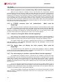
3.2.- F.A.Q
3.2.1 Some equipment is not communicating. What could be happening?
Make sure your computer is switched on and in a mode which can communicate, ensuring
particularly that it is not in the set up or starting up mode. Make sure your computer is connected to a
PC or a compatible converter and that the wiring is correct. Make sure there is no possibility of any
interference in the cable run from the device to the PC or between the device and the converter. If you
are connected to a converter, check that the latter is properly connected to the PC. Verify that the grid
is not overloaded with an excessive amount of devices. If your computer is connected by way of a 232485 converter make sure that the switches are in the correct position. Make sure that the equipment
bus does not have devices that communicate at different speeds or have the same device number.
Check that the PC port is working properly.
3.2.2
A TCP2RS converter does not communicate.
happening?
What could be
Make sure your computer is switched on and connected to the communications network. Make
sure there is no possibility of any interference in the cable run from the converter to the PC. Make sure
your PC is correctly connected to the communications network and can communicate with other
equipment connected to the network (for example with another PC). If you are using a router, make
sure the communication port is redirected in the router, to the converter address.
3.2.3 I cannot see the applet. What could be happening?
Check that the local computer has the Microsoft Internet Explorer, Netscape (Mozilla) or
Firefox browser installed. Ensure that the Java Virtual Machine JRE 1.6 (6.0) or later is installed. If they
are not installed the browser will provide information and guide us through the installation process.
If the applet appears but a message is displayed warning that there is “no communication
with the server” or “the required information could not be recovered” ensure that the
communications engine is running.
3.2.4 The Applet does not display the texts properly. What could be
happening?
It is possible that some fonts applied to the controls when designing a report or a SCADA
screen do not exist on the machine on which the applet is downloaded and, as a consequence, the
font chosen may be markedly different from the original.
3.2.5 The values display is not what I expected. What could be happening?
It is possible that a conditional control or a formula refers to a variable of a device which does
not communicate or that has not yet been interrogated for the first time. In a SCADA screen, if we are
dealing with a condition nothing will appear and if we are dealing with a formula a dash ("-") appears
until the value can start. In a report, if there is no data in this period and we cannot assess the
condition of a conditional control, nothing will be displayed and if we cannot assess the definition the
same will occur.
It may occur that when assessing the formula we come across an invalid operation, such as
the square root of a negative number or a zero division, in this case a question mark ("?") appears on
the SCADA screen and the report will show the definition of the formula. If we are unable to assess the
condition of a conditional control, nothing will be displayed.
It may not be possible to represent the assessment of the formula of an expression, because
either its control or assessment configuration returned an out of range value. In this case the “#”
character will appear.
30
User Manual
PowerStudio
3.2.6 An event is not behaving as expected. What could be happening?
When an event does not occur when you think it should, or vice versa, check that this condition
can be fulfilled and make sure the event is enabled at some time by the calendar and that the condition
can be fulfilled during that interval. Verify that the devices involved in assessing the condition of the
event communicate properly and ensure that the communication engine is running. Make sure you
have permission to see this type of event and you have checked the notify and/or register box.
If the incident appears not to have carried out actions that have been defined, check what has
actually occurred in the list of events. If the event has still not produced the programd action or actions,
check that the equipment upon which it should have acted is on and communicating correctly. Should
the action involve the running of an external application, check that the application is properly installed
and that the command and parameters are correct (you can put this action in a run control in a SCADA
screen test to see if it behaves as expected)
3.2.7 I can’t paint the graph correctly. What could be happening?
If the graph appears to have dots missing, verify that this is not because the variables are
being represented with different periods.
If the bar charts has widths that are not correct, ensure that the values are separated by the
distance marked by the driver period. For example, if a device saves data every 5 minutes and we
change the period to 15 minutes, the bars will be superimposed when displaying the bar graphs for the
values prior to the change of period (every 5 minutes). If we change the period to a lower value, the
bars prior to the change will appear narrower than necessary. In any case, the bar graphs of values
separated by the distance shown in the Driver registration period will always appear correctly.
If you do not see any values when you think there should be, ensure that you have not zoomed
in an area without values or that the Y-axis is not forcing levels for values which do not exist.
3.2.8 The Paint Pot is not working correctly. What could be happening?
If when placing the paint pot control on a SCADA screen, it does not behave in the manner
expected, ensure that:
1.- The condition or conditions defined are right for each color.
2.- The area in which the control is positioned has a uniform color. It is possible that the area
where the paint pot is positioned has different colored dots but with very similar tones, which at first
sight appear the same. The paint pot control only spreads through identical colors.
3.- The area to be filled with the colors defined in control is not part of another control. The
paint pot control only interacts with the screen background and does not take into account any of the
other controls. Do not attempt to use the paint pot to fill, for example, an image by way of the image
type control.
User Manual
31
PowerStudio
PowerStudio
3.2.9 The software is not sending e-mails. What might be happening?
Check that your anti-virus is not blocking the software.
For security purposes, the software does not send e-mails if the mail server does not have the
Transport Layer Security (TSL) option activated and the mail server only supports Plain, Login or
NTLM authentication protocols, since these are not very secure for sending information.
If this is the case:
To increase the security of your mail server and in order to allow the software to send e-mails,
TLS/SSL encryption should be enabled. If you want, you can add another authentication
method such cram-md5, digest-md5, gssapi or an external one.
If TLS has not been activated, one of the previously suggested authentication proposals
should be added; the protocols already functioning in the mail server can be retained, since
they will not be used by the software. The authentication method for the smtp server CANNOT
be any of the following: plain, login or ntlm.
If the system still does not send mails check that your e-mail server has a user with the same
name as the configured address. The software will use the configured e-mail address for the
user.
3.2.10 Can I launch external applications from applet?
For security reasons, Java Applets have some fairly significant limitations with regards
accessing the resources of the local machine on which they are running. One of these restrictions is
being able to run applications on the local machine. Nevertheless, this restriction may be disabled by
adding the following line to the java.policy permissions file situated in the installation of the JRE virtual
machine:
permission java.io.FilePermission "<<ALL FILES>>", "execute";
It must be noted, however, that the Applet cannot directly display files from the run control, in
the way SCADA can. So, if we wanted to show an image in applet it is not enough to enter the name of
the image in the run control, but rather we should enter the application we want to use to show the
image and, as a parameter, the image to show.
N.B: The option to launch external applications very much depends on the system in which
applet is running, and it is highly probable that it will only work in the system for which the application
has been developed.
3.2.11 How can I see the applet from a machine which is not running Windows?
The applet can be viewed without carrying out any other special action from all operating
systems that have Java Virtual Machine 1.5 (5.0) or later and an HTML browser. Among others, the
following operating systems would satisfy these requirements: Windows, Linux, Solaris SPARC,
Solaris x86, Solaris AMD64, Linux AMD64, etc.
3.2.12 Can I directly connect with a known IP when I execute the Applet? What
happens if there’s authentication? What parameters can I use to
configure the Applet application launch?
When launching the Applet, you have the option to add parameters to modify its behaviour.
The available parameters are as follows:
•
32
undecorated Launches the client without borders (nor captions, nor margins for resizing).
This feature is used to run the applet on embedded screens (Multipunto, CHAdeMO, etc.).
Example: java -jar AppletScada.jar undecorated
User Manual
PowerStudio
•
classic Launches the client with the classic look and feel instead of the substance option.
Example: java -jar AppletScada.jar classic
•
multipleinstance Launches the client with permission to run if there is another client open.
For safety purposes, the last version would check to ensure that there were no other clients
open when running, and would not run if there were. We can override this restriction with this
parameter. Example: java -jar AppletScada.jar multipleinstance
•
user:user password:password Automatically logs in with the specified user and
password. Example: java -jar AppletScada.jar user:john password:xh234
•
sleep:x Establishes the refresh time of SCADA screens for monitoring devices and for
checking active and reported events. It is set in milliseconds, with a minimum of 20
ms. Example: java -jar AppletScada.jar sleep:200
•
address[:port] Indicates the http address (IP or name) to which the client will attempt to
connect. If necessary (the engine is not in port 80), the port may also be indicated.
Example: java -jar AppletScada.jar powerstudio.circutor.com:8080
3.2.13 I am making my first screen or report and I cannot add a background
image or a still picture. What is happening?
You should remember that the images that can be included on the SCADA screens and the
reports must have been added previously through the image manager. Therefore it is necessary before
starting to design a screen or report to add the images you will need through the image manager.
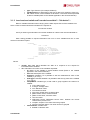
3.2.14 What can be "counted"?
Any event added to the system contains a variable that indicates how many times it has been
enabled, how many times it has been recognized, how many times it has been deactivated, how long
has it been active, if it is active at the moment and how much time has elapsed since it was last
enabled.
One can also count how many times something has occurred in the current hour, day, etc. For
this purpose a forced calculated variable will be created and initialized to 0 and an event, which when a
condition is fulfilled performs the action of forcing that variable to its same value plus one unit.
[R$CAL_FORCED.COUNTER1]=[R$CAL_FORCED.COUNTER1]+1
We then just need to add an event that would reset this counter to 0 when the date was
outside XX / XX / XX 00:00:00 (00:00:00 hours each day) with which the counter would have the
number activations of the day in course. The counter reset could be carried out with a variable forced
control on the SCADA screen, in this case manual instead of automatic.
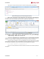
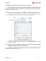
3.2.15 I would like to export the report data in order to process it later. How can
I do it?
The data displayed in a report is log data grouped together for the period of the report,
therefore we have a value per period (if it is an expression where several variables are involved the
value of each variable is recovered for the period of the report and the expression assessed).
For practical purposes, the values of the variables that are used in the reports can be
consulted by requesting / services / user / records.xml (which is documented in the XML user
requests section).
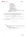
Imagine then we have a report with the following appearance:
User Manual
33
PowerStudio
PowerStudio
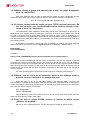
Report generated
The report is grouped by day, in particular, we are viewing November 22th. It shows that there
are a number of values in red, inside boxes, the first value on the top left corner corresponds to the
variable “01_CVM144.AE”.
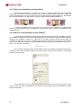
To see that value through a HTTP / XML request to the server we can do the following:
http://192.168.3.3:8083/services/user/records.xml?begin=21112013230000?end=221120132300
00?period=ALL?var=01_CVM144.AE
34
User Manual
PowerStudio
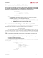
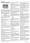
This request, if carried out with the browser, will return something similar to the following:
Result of the request from the Internet Explorer browser
Where, in the "value" field we have the desired value. This request can be done directly from,
for example, the Excel spreadsheet, by simply writing this request in the dialogue "Open" (instead of
the name of a file). Excel will interpret the previous XML and generate a table with data:
"Open" request with Excel 2010. In D1 we have the data.
3.2.16 I tried to make a table with the client application and I get the Message
"Table too Big." What can I do to see it?
The client is a Java application. As a Java application it runs on a virtual machine with a limited
memory for it to run assigned by default. Normally this amount of memory allocated by default is
sufficient for running the program. But perhaps for very large tables this memory is insufficient.
For these cases it is possible to run the client application forcing the virtual machine to assign
more memory to the program. This is accomplished by running the program from the command line
with a parameter indicating the maximum and minimum memory available for the program.
java -Xm256m -Xmx1024m –jar AppletScada.jar
As you can see the parameters Xm-and-Xmx allocate a minimum and a maximum quantity to
the program.
User Manual
35
PowerStudio
PowerStudio
3.2.17 How can I simulate a control switch?
To simulate the behaviour of a switch (e.g. to act on a digital output) we need a conditional
control and two controls to force the variable. The conditional control would contain two images, one
with the representation of an open switch, with the condition that the digital variable is 1, and another
with the representation of a closed switch, with the condition that the digital variable is 0.
A control is positioned on the left part of the control to force a variable with a digital output
value at 1, while another control is positioned on the right-hand section to force a variable with the
output value at 0.
3.2.18 How do I add animation to the SCADA?
To add a small animated image the conditional control combined with the "second" function in
the condition is added. First, save the images that make up the animation using the image manager.
Suppose your animation consists of a sequence of 3 images. Assume further that we want our
animation to change every second. Therefore we will have to create a list of formulae on the SCADA
screen which will return module 3 of the "second" function (which will vary between the values, 0, 1
and 2). The function is as follows:
mod(second,3)
Let us suppose that this function is called MOD. Now we can define a conditional control with 3
conditions, where each condition displays one of the images that form the animation. The following
shows control properties:
The result is that one of the images that make up the animation is shown every second. As can
be seen, there are many combinations to be carried out and a large variety of opportunities to exploit
using this technique.
36
User Manual
PowerStudio
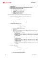
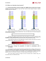
3.2.19 How can I simulate a level control?
There are two ways to do a level control on a SCADA screen. The first one is to use a
conditional control, where each control is an image with a different level and where every condition
indicates what should be fulfilled to reach this level. Here are some images showing us specific
examples with their conditions:
[CVM K 1.VI1] == 215
[CVM K 1.VI1] == 221
[CVM K 1.VI1] == 224
Another option would be to draw the level control at the bottom of the SCADA screen and use
various paint pot controls to paint the desired zone. Thus, we could draw on the screen background
something like the following:
The inner part, although it seems all the same color (white), it is not and is divided into grids
with different whites indistinguishable one from the other and by the human eye (for example, it is
impossible to distinguish between white RGB 255.255.255 and white RGB 254.255.255).
Then we place the paint pot on each table with the desired condition and tolerance 0 to prevent
painting adjacent tables, which are very similar in color.
With this, the result is a progress bar (or control level) which can be configured as desired.
3.2.20 How can I change the properties of control in accordance with a
condition?
The properties of control cannot be changed in accordance with a condition. However, we can
simulate the change of these properties, using a conditional control. Thus, for example, if we wish to
change the color of a text in accordance with a condition we add a conditional control with two text type
controls which are exactly the same but of a different color, and specify which conditions need to be
fulfilled for each one to be shown. Likewise, we can also change the orientation, font, size, etc.
We can also make a control be an image or a text in accordance with a condition using, as in
the previous case, the conditional control.
User Manual
37
PowerStudio
PowerStudio
3.2.21 How can I know the status of a device?
All devices have a variable called STATUS that shows the status of the device using a
numerical value (for example, [CVM144.STATUS]). The meaning of this variable is the same for all
devices and can be used in the conditional expressions (see the appendix to check the types of
variables and their possible values)
3.2.22 How can I display documents from a SCADA screen?
To show documents previously stored on the PC the run control can be used. If we wish to
show a PDF file, we can enter its name directly (including the complete path) in the program field, so
that the file will open in the related, defined program when running the screen and clicking on the
control. Likewise, we can do this with any file type which has an associated program to open it. (DOC,
TXT, HTML, WAV, MP3, MPG, AVI, etc.)
N.B: This option will not work on systems which do not run Windows, nor when using the
applet.
3.2.23 How can I obtain an event according to the status of a device?
To produce an event according to the status of one or more devices, use the STATUS variable
of the device in the event activation status. The possible values of the STATUS variable can be seen in
the variable type appendix.
Since the events generate a number of variables associated to them, we can even see how
many times an event was enabled, how many times it was deactivated, how many it was recognized
and how long it was enabled.
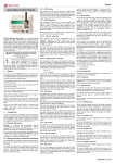
3.2.24 How can I produce sounds in response to an event?
To produce a sound in response to an event, we should add an action to run an external
program and enter the corresponding (WAV, MP3, etc.) with its full path in the program field. For the
action to take effect, you will need to have a program installed that can play back this type of file (for
example, Windows Media Player, Sonique, Winamp, etc.).
If what is needed is simply reproducing a bleep on the client application, an action associated
with this event can be added to carry it out. Likewise this action can occur during activation, upon
acknowledgement, on deactivation or while active.
Support for the audible alarm action on the client in response to an event
38
User Manual
PowerStudio
3.2.25 How do I show documents in response to an event?
In a similar manner to the previous point, adding an action to run an external program and
entering the file to be shown (PDF, TXT, DOC, etc.) and its corresponding path. For the action to take
effect, you will need to have a program installed that can read this type of file (for example, Microsoft
Word, Adobe Acrobat Reader, etc.).
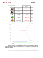
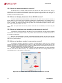
3.2.26 How can I communicate with a TCP2RS+ converter by way of a router?
To communicate with a TCP2RS+ converter located in a sub-network different to the network
in which the software is located, we can use a router as shown in the following image
The TCP2RS+ converter should be added as follows
1- Enter the router address (192.168.120.201)–In the “Converter Address” field.
2- Redirect ports ‘10001 ’and ‘30718’ in the router to the converter address (192.168.15.205)
(see router manual)
3.2.27 There are screens on which I cannot see the text of the controls properly
or they are truncated. How can I solve this?
The screens are designed to be properly viewed with a minimum size of 1024x768. You must
increase the size of the window to the recommended minimum size, if your screen is configured at
1024x768 you must maximise the screen.
User Manual
39
PowerStudio
PowerStudio
3.2.28 When viewing a graph and selecting the tooltip, the graph disappears.
How can I solve this?
With some platforms when a graph is made and the tooltip is viewed it disappears and the
background turns black. If this occurs you must start the client with the following command line:
java –jar –Dsun.java2d.d3d=false AppletScada.jar
3.2.29 I cannot connect with the engine or some TCP/IP devices has errors. On
the Java console I see: java.net.BindException: Address already in use:
connect. How can I solve this?
The PowerStudio client application continuously makes many connections to the server. In
Windows the open sockets (ports) for making the connection are limited, and in addition they cannot
be used for a specific amount of time after having been freed up (WAIT). Thus, in Windows XP, for
example, by default the user applications are allowed to use ports 1024 to 5000 and also by default, a
port will remain in the TIME_WAIT state for 4 minutes after it is closed, before finally being freed up by
the operating system.
In Windows it is possible to change this policy by modifying or creating two registry keys that
define this behavior (you need to execute regedit application for Windows). These keys are:
MaxUserPort
TcpTimedWaitDelay
Located in:
HKEY_LOCAL_MACHINE\System\CurrentControlSet\Services\Tcpip\Parameters
Both keys are DWORD type and you have to create them if they are not available. In the first
we assign the maximum port number, which is set at 5000 by default and we can set it at 20000 (in
decimal format). In the second we define the time in seconds that we want a port to remain reserved
after having closed it (for example, we can set it at 30 in decimal format). These parameters must be
verified in both the server and the client computers. Remember to reboot the PC for the changes to
become effective.
For other operating systems consult the specific method for configuring this behaviour.
3.2.30 When I run the client as an embedded applet in the webpage within a
browser, how can I access as an anonymous user?
When the client is run as an embedded applet in the webpage within a browser, the
authentication is managed by the browser itself. The authentication screen displayed by the browser,
usually only allows the user name and password to be entered. If you wish to access as an anonymous
user you must use the following access data:
User: anonymous
Password:anonymous
This will provide access to the system as an anonymous user as long as this profile has been
defined in the engine (by means of the editor).
3.2.31 I’m not able to create SCADA screens or reports or define events
¿Where’s the problem?
May be you have a standard version. You should acquire a SCADA or Deluxe version.
40
User Manual
PowerStudio
4.- MAINTENANCE AND TECHNICAL SERVICE
In the case of any query in relation to unit operation or malfunction, please contact
the CIRCUTOR, SA Technical Support Service.
Technical Assistance Service
Vial Sant Jordi, s/n 08232 - Viladecavalls (Barcelona)
Tel.: 902 449 459 (Spain) / +34 937 452 900 (outside of Spain)
email: [email protected]
5.- GUARANTEE
CIRCUTOR guarantees its products against any manufacturing defect for two years after the delivery
of the units.
CIRCUTOR will repair or replace any defective factory product returned during the guarantee period.
•
No returns will be accepted and no unit will be repaired or replaced if it is
not accompanied by a report indicating the defect detected or the
reason for the return.
•
•
User Manual
The guarantee will be void if the units has been improperly used or the
storage, installation and maintenance instructions listed in this manual
have not been followed. "Improper usage" is defined as any operating or
storage condition contrary to the national electrical code or that
surpasses the limits indicated in the technical and environmental
features of this manual.
CIRCUTOR accepts no liability due to the possible damage to the unit or
other parts of the installation, nor will it cover any possible sanctions
derived from a possible failure, improper installation or "improper usage"
of the unit. Consequently, this guarantee does not apply to failures
occurring in the following cases:
- Overvoltages and/or electrical disturbances in the supply;
- Water, if the product does not have the appropriate IP classification;
- Poor ventilation and/or excessive temperatures;
- Improper installation and/or lack of maintenance;
- Buyer repairs or modifications without the manufacturer's authorisation.
41
CIRCUTOR, SA
Vial Sant Jordi, s/n
08232 - Viladecavalls (Barcelona)
Tel: (+34) 93 745 29 00 - Fax: (+34) 93 745 29 14
www.circutor.es [email protected]