1
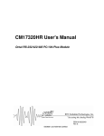
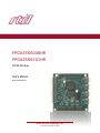
FPGA35S6046HR FPGA35S6101HR FPGA Module User’s Manual BDM-610010048 Rev. A RTD Embedded Technologies, Inc. AS9100 and ISO 9001 Certified RTD Embedded Technologies, Inc. 103 Innovation Boulevard State College, PA 16803 USA Telephone: 814-234-8087 Fax: 814-234-5218 www.rtd.com [email protected] [email protected] Revision History Rev A Initial Release Advanced Analog I/O, Advanced Digital I/O, aAIO, aDIO, a2DIO, Autonomous SmartCal, “Catch the Express”, cpuModule, dspFramework, dspModule, expressMate, ExpressPlatform, HiDANplus, “MIL Value for COTS prices”, multiPort, PlatformBus, and PC/104EZ are trademarks, and “Accessing the Analog World”, dataModule, IDAN, HiDAN, RTD, and the RTD logo are registered trademarks of RTD Embedded Technologies, Inc (formerly Real Time Devices, Inc.). PS/2 is a trademark of International Business Machines Inc. PCI, PCI Express, and PCIe are trademarks of PCI-SIG. PC/104, PC/104-Plus, PCI-104, PCIe/104, PCI/104-Express and 104 are trademarks of the PC/104 Embedded Consortium. All other trademarks appearing in this document are the property of their respective owners. Failure to follow the instructions found in this manual may result in damage to the product described in this manual, or other components of the system. The procedure set forth in this manual shall only be performed by persons qualified to service electronic equipment. Contents and specifications within this manual are given without warranty, and are subject to change without notice. RTD Embedded Technologies, Inc. shall not be liable for errors or omissions in this manual, or for any loss, damage, or injury in connection with the use of this manual. Copyright © 2013 by RTD Embedded Technologies, Inc. All rights reserved. RTD Embedded Technologies, Inc. | www.rtd.com iii FPGA35S6046/FPGA35S6101 User’s Manual Table of Contents 1 2 3 4 5 Introduction 7 1.1 Product Overview........................................................................................................................................................................ 7 1.2 Board Features ........................................................................................................................................................................... 7 1.3 Ordering Information ................................................................................................................................................................... 9 1.4 Contact Information .................................................................................................................................................................... 9 1.4.1 Sales Support 9 1.4.2 Technical Support 9 Specifications 10 2.1 Operating Conditions ................................................................................................................................................................ 10 2.2 Electrical Characteristics .......................................................................................................................................................... 10 Board Connection 11 3.1 Board Handling Precautions ..................................................................................................................................................... 11 3.2 Physical Characteristics ............................................................................................................................................................ 11 3.3 Connectors and Jumpers .......................................................................................................................................................... 12 3.3.1 External I/O Connectors 12 CN3: Xilinx JTAG Programming Header 12 CN8: High Speed Digital I/O Connector 13 CN9: Digital I/O Connector 14 CN10, CN11, CN12, CN13: RS-232/422/485 Transceiver Connectors 14 3.3.2 Bus Connectors 15 CN1(Top) & CN2(Bottom): PCIe Connector 15 3.3.3 Jumpers 15 JP4, JP5, JP6: Pull up/Pull down Jumper 15 JP1: Embedded Programmer Enable 15 3.3.1 Solder Jumper 15 B1: Pull up Voltage 15 3.4 Steps for Installing .................................................................................................................................................................... 16 IDAN Connections 17 4.1 Module Handling Precautions ................................................................................................................................................... 17 4.2 Physical Characteristics ............................................................................................................................................................ 17 4.3 Connectors and Jumpers .......................................................................................................................................................... 18 P2: RS-232/422/485 Transceiver Connector 18 P3: Digital I/O Connector 18 P4: High Speed Digital I/O Connector 20 4.3.1 Bus Connectors 22 CN1(Top) & CN2(Bottom): PCIe Connector 22 4.3.2 Jumpers 22 JP4, JP5, JP6: Pull up/Pull down Jumper 22 JP1: Embedded Programmer Enable 22 4.3.3 Solder Jumper 22 B1: Pull up Voltage 22 4.4 Steps for Installing .................................................................................................................................................................... 23 Functional Description 24 5.2 Oscillator ................................................................................................................................................................................... 24 5.3 EEPROM .................................................................................................................................................................................. 24 5.4 DDR2 SRAM ............................................................................................................................................................................. 24 5.5 Digital I/O .................................................................................................................................................................................. 25 5.7 Embedded Digilent® USB JTAG Programmer ......................................................................................................................... 26 RTD Embedded Technologies, Inc. | www.rtd.com iv FPGA35S6046/FPGA35S6101 User’s Manual 6 Register Address Space 6.1 27 BAR0 – FPGA Example Register Map ..................................................................................................................................... 27 6.1.1 R_ID (Read) 27 6.1.2 R_STATUS (Read) 27 6.1.3 R_EEPROM (Read/Write) 27 6.1.4 R_PORT1_IN (Read) 28 6.1.5 R_PORT1_OUT (Write) 28 6.1.6 R_PORT1_DIR (Read/Write) 28 6.1.7 R_PORT2L_IN (Read) 28 6.1.8 R_PORT2L_OUT (Write) 28 6.1.9 R_PORT2L_DIR (Read/Write) 28 6.1.10 R_PORT2H_IN (Read) 28 6.1.11 R_PORT2H_OUT (Write) 28 6.1.12 R_PORT2H_DIR (Read/Write) 28 6.1.13 R_DDR_RD_DATA (Read) 28 6.1.14 R_DDR_WR_DATA (Read/Write) 28 6.1.15 R_DDR_ADDR (Read/Write) 28 6.1.16 R_DDR_STATUS (Read) 29 6.1.17 R_COM1_OUT (Read/Write) 29 6.1.18 R_COM1_IN (Read) 30 6.1.19 R_COM2_OUT (Read/Write) 30 6.1.20 R_COM2_IN (Read) 30 6.1.21 R_COM3_OUT (Read/Write) 31 6.1.22 R_COM3_IN (Read) 31 6.1.23 R_COM4_OUT (Read/Write) 32 6.1.24 R_COM4_IN (Read) 32 7 Troubleshooting 33 8 Additional Information 34 9 8.1 PC/104 Specifications ............................................................................................................................................................... 34 8.2 PCI and PCI Express Specification .......................................................................................................................................... 34 8.3 Serial Port Transceivers ........................................................................................................................................................... 34 Limited Warranty RTD Embedded Technologies, Inc. | www.rtd.com 35 v FPGA35S6046/FPGA35S6101 User’s Manual Table of Figures Figure 1: Board Dimensions ................................................................................................................................................................................... 11 Figure 2: Board Connections .................................................................................................................................................................................. 12 Figure 3: Example 104™Stack ............................................................................................................................................................................... 16 Figure 4: IDAN Dimensions .................................................................................................................................................................................... 17 Figure 5: Example IDAN System ............................................................................................................................................................................ 23 Figure 6: FPGA35S6 Block Diagram ...................................................................................................................................................................... 24 Figure 7: CN9 Digital I/O Circuitry .......................................................................................................................................................................... 25 Table of Tables Table 1: Ordering Options ........................................................................................................................................................................................ 9 Table 2: Operating Conditions ................................................................................................................................................................................ 10 Table 3: Electrical Characteristics .......................................................................................................................................................................... 10 Table 4: CN3 Programming Header ....................................................................................................................................................................... 12 Table 5: CN8 I/O Pin Assignments ......................................................................................................................................................................... 13 Table 6: CN9 I/O Pin Assignments ......................................................................................................................................................................... 14 Table 7: CN10, CN11, CN12, CN13 I/O Pin Assignments ..................................................................................................................................... 14 Table 8: Pull up/Pull down Jumper options ............................................................................................................................................................ 15 Table 9: B1 Pull up Voltage .................................................................................................................................................................................... 15 Table 10: P2 Pin Assignments ................................................................................................................................................................................ 18 Table 11: P3 Pin Assignments ................................................................................................................................................................................ 19 Table 12: P4 Pin Assignments ................................................................................................................................................................................ 20 Table 13: Pull up/Pull down Jumper options .......................................................................................................................................................... 22 Table 14: B1 Pull up Voltage .................................................................................................................................................................................. 22 Table 15: Transceiver Configuration....................................................................................................................................................................... 25 Table 16: FPGA Example Register Map................................................................................................................................................................. 27 RTD Embedded Technologies, Inc. | www.rtd.com vi FPGA35S6046/FPGA35S6101 User’s Manual 1 Introduction 1.1 Product Overview The FPGA35S6 series of FPGA boards are designed to provide a platform to create any digital I/O that is required for your application. It interfaces with the PCIe bus and features a Xilinx Spartan 6 FPGA with a 27 Mhz oscillator and 1Gb of DDR2 SDRAM. The FPGA35S6046 and FPGA35S6101 provide 32 RS-232/422/485 I/O, 24 5V tolerant I/O and 40 3.3V tolerant high speed I/O. 1.2 Board Features Xilinx Spartan 6 System level features o XC6SLX45T (FPGA35S6046HR) 43,661 Logic Cells 2,489 kb of internal RAM 116 18Kb (2088 Kb Max) Block RAM 401 kB Distributed RAM o XC6SLX100T (FPGA35S6101HR) 101,261 Logic Cells 5,800 kb of internal RAM 268 18Kb (4,824 Kb Max) Block RAM 976 kB Distributed RAM o RAM hierarchical memory: Each block RAM has two independent ports Programmable Data Width o Integrated Endpoint block for PCI Express o Integrated Memory Controller 1 Gb of DDR2 SDRAM Supports access rates of up to 800Mb/s o Dedicated carry logic for high-speed arithmetic o Abundant logic resources with increased logic capacity Optional shift register or distributed RAM support Efficient 6-input LUTs LUT with dual flip-flops o Four dedicated DLLs for advanced clock control Phase shift input clock by 0, 90, 180, 270 Multiply input clock by 2 to 32 Divide input clock by 1 to 32 Digital I/O Connectors o 32 RS-232/422/485 I/O Four connectors Each connector can support a single full RS-232 port or two TX/RX only ports Up to 1 Mbps in RS-232 mode Up to 20 Mbps in RS-422/485 mode ESD Protected o 24 5V tolerant Digital I/O Selectable pull-up/pull-down per byte Pull-up can be 3.3V or 5V ESD Protected Can be used as LVDS Input/Output or LVTTL Input/Output o 40 3.3V tolerant High-Speed I/O ESD Protected Can be used as LVDS Input or LVTTL Input/Output Fully supported by Xlinx development system o ISE WebPACK (free download from http://www.xilinx.com) o ISE Design Suite Embedded Digilent® USB JTAG Programmer o Allows programming from the host computer o Compatible with Xilinx tools, including iMpact and ChipScope RTD Embedded Technologies, Inc. | www.rtd.com 7 FPGA35S6046/FPGA35S6101 User’s Manual PCI Express Bus: o PCIe/104 Universal Board Interfaces with Type 1 or Type 2 bus No re-population o Provides 2.5 Gbps in each direction o In-band interrupts and messages o Message Signaled Interrupt (MSI) support RTD Embedded Technologies, Inc. | www.rtd.com 8 FPGA35S6046/FPGA35S6101 User’s Manual 1.3 Ordering Information The FPGA35S6 series of FPGA boards is available in the following options: Table 1: Ordering Options Part Number FPGA35S6046HR FPGA35S6101HR IDAN-FPGA35S6046HR IDAN-FPGA35S6101HR Description PCIe/104 Spartan-6 XC6SLX45T User Programmable FPGA Module PCIe/104 Spartan-6 XC6SLX100T User Programmable FPGA Module PCIe/104 Spartan-6 XC6SLX45T User Programmable FPGA Module in IDAN enclosure PCIe/104 Spartan-6 XC6SLX100T User Programmable FPGA Module in IDAN enclosure A Starter Kit is available for any of the options, which includes the appropriate programming cable. Contact RTD Sales for more information. The FPGA35S6 is a general use FPGA module, allowing you to design your own FPGA. It has support for custom oscillator and larger Xilinx Spartan 6 FPGAs. Please contact RTD Embedded Technologies for more information on custom FPGA35S6 products and custom FPGA designs. The Intelligent Data Acquisition Node (IDAN™) building block can be used in just about any combination with other IDAN building blocks to create a simple but rugged 104™ stack. This module can also be incorporated in a custom-built RTD HiDAN™ or HiDANplus High Reliability Intelligent Data Acquisition Node. Contact RTD sales for more information on our high reliability systems. 1.4 Contact Information 1.4.1 SALES SUPPORT For sales inquiries, you can contact RTD Embedded Technologies sales via the following methods: Phone: E-Mail: 1.4.2 1-814-234-8087 [email protected] Monday through Friday, 8:00am to 5:00pm (EST). TECHNICAL SUPPORT If you are having problems with you system, please try the steps in the Troubleshooting section of this manual. For help with this product, or any other product made by RTD, you can contact RTD Embedded Technologies technical support via the following methods: Phone: E-Mail: 1-814-234-8087 Monday through Friday, 8:00am to 5:00pm (EST). [email protected] RTD Embedded Technologies, Inc. | www.rtd.com 9 FPGA35S6046/FPGA35S6101 User’s Manual 2 Specifications 2.1 Operating Conditions Table 2: Operating Conditions Symbol Vcc5 Vcc3 Vcc12 Ta Ts RH Parameter 5V Supply Voltage 3.3V Supply Voltage 12V Supply Voltage Operating Temperature Storage Temperature Relative Humidity MTBF Mean Time Before Failure Test Condition Min 4.75 n/a n/a -40 -40 0 Non-Condensing Telcordia Issue 2 30°C, Ground benign, controlled Max 5.25 n/a n/a +85 +85 90% Unit V V V C C % TBD Hours 2.2 Electrical Characteristics Table 3: Electrical Characteristics Symbol P Icc Parameter Power Consumption(1) 5V Input Supply Current(1) Test Condition Vcc5 = 5.0V Active PCIe/104 Bus Differential Output Voltage DC Differential TX Impedance Differential Input Voltage DC Differential RX Impedance Electrical Idle Detect Threshold VIH VIL VOH VOL VTH RIN RTERM VOD VCM VIH VIH VIL VOH VOL Note: Min Typ 2.5 500 0.8 80 0.175 80 65 Serial Transceivers RS-232 mode RS-232 mode RS-232 mode RS-232 mode RS-422/485 mode RS-422/485 mode TERM = 0 -7V ≤ VIN ≤ 12V Termination Resistance RS-422/485 mode TERM = 1 -7V ≤ VIN ≤ 12V Output Differential Voltage RS-422/485 mode RL=100Ω (RS-422) RL=54Ω (RS-485) Driver Common Mode Output Voltage RS-422/485 mode Digital I/O Input High Voltage CN9 Input High Voltage CN8 Input Low Voltage CN8,CN9 Output High Voltage IO = -12mA CN8,CN9 Output Low Voltage IO = 12mA CN8,CN9 5V Output CN8,CN9 DDR2 Interface Access Rate(2) Input High Voltage Input Low Voltage Output High Voltage Output Low Voltage Input Differential Threshold Input Resistance Max Unit W mA 1.2 120 1.2 120 175 V Ω V Ω mV 2.0 -15 5.0 -7.0 -200 96 1.5 1.2 5.5 -5.5 -125 +15 0.6 7.0 -5.0 -50 V V V V mV kΩ 100 120 155 Ω V 2.0 1.5 3.0 V 2.0 2.0 -0.5 2.6 0 5.5 3.6 0.8 3.3 0.4 200 V V V V V mA 250 800 Mb/s (1): Typical power consumption based on RTD’s FPGA example. (2): Proving by design, not production tested. For additionally electrical characteristic of the Spartan 6 I/O refer to http://www.xilinx.com RTD Embedded Technologies, Inc. | www.rtd.com 10 FPGA35S6046/FPGA35S6101 User’s Manual 3 Board Connection 3.1 Board Handling Precautions To prevent damage due to Electrostatic Discharge (ESD), keep your board in its antistatic bag until you are ready to install it into your system. When removing it from the bag, hold the board at the edges, and do not touch the components or connectors. Handle the board in an antistatic environment, and use a grounded workbench for testing and handling of your hardware. 3.2 Physical Characteristics Weight: Approximately 63.5 g (0.14 lbs.) Dimensions: 90.17 mm L x 95.89 mm W (3.550 in L x 3.775 in W) Figure 1: Board Dimensions RTD Embedded Technologies, Inc. | www.rtd.com 11 FPGA35S6046/FPGA35S6101 User’s Manual 3.3 Connectors and Jumpers CN8: High Speed Digital I/O CN10: RS-232/422/485 CN9: Digital I/O CN11: RS-232/422/485 JP4, JP5 & JP6: Pull up/Pull down Jumper CN12: RS-232/422/485 CN13: RS-232/422/485 CN3: Programming Header B2 on bottom side CN1 & CN2: PCIe Connector JP1: Embedded Programmer Enable Figure 2: Board Connections 3.3.1 EXTERNAL I/O CONNECTORS CN3: Xilinx JTAG Programming Header Connector CN3 provides a connection to the Xilinx JTAG programming header. The pin assignment for CN3 is shown below. This connector header mates with the Xilinx OEM programming cable. Table 4: CN3 Programming Header 3.3V VRef TMS TCK TDO TDI N/C N/C RTD Embedded Technologies, Inc. | www.rtd.com 2 4 6 8 10 12 14 12 1 3 5 7 9 11 13 GND GND GND GND GND GND GND FPGA35S6046/FPGA35S6101 User’s Manual CN8: High Speed Digital I/O Connector Connector CN8 provides 40 digital I/O lines, along with a +5V pin and ground pins. These signals are 3.3V tolerant. The signal names reflect the signal names I n the Xilinx UCF file with the device pin out. CN8 is attached to Bank 1, and supports any of the Spartan 6 I/O Standards that use a 3.3V VCCO and no reference voltage. This includes LVTTL, LVCMOS33 input and output, and LVDS_33 input. LVDS output is not supported in Bank 1. Table 5: CN8 I/O Pin Assignments Port2_n[0] Port2_n[1] Port2_n[2] Port2_n[3] GND Port2_n[4] Port2_n[5] Port2_n[6] Port2_n[7] GND Port2_n[8] Port2_n[9] Port2_n[10] Port2_n[11] GND Port2_n[12] Port2_n[13] Port2_n[14] Port2_n[15] GND Port2_n[16] Port2_n[17] Port2_n[18] Port2_n[19] GND RTD Embedded Technologies, Inc. | www.rtd.com 2 4 6 8 10 12 14 16 18 20 22 24 26 28 30 32 34 36 38 40 42 44 46 48 50 1 3 5 7 9 11 13 15 17 19 21 23 25 27 29 31 33 35 37 39 41 43 45 47 49 13 Port2_p[0] Port2_p[1] Port2_p[2] Port2_p[3] GND Port2_p[4] Port2_p[5] Port2_p[6] Port2_p[7] GND Port2_p[8] Port2_p[9] Port2_p[10] Port2_p[11] GND Port2_p[12] Port2_p[13] Port2_p[14] Port2_p[15] GND Port2_p[16] Port2_p[17] Port2_p[18] Port2_p[19] +5V FPGA35S6046/FPGA35S6101 User’s Manual CN9: Digital I/O Connector Connector CN9 provides 24 digital I/O lines, along with a +5V pin and ground pins. All I/O have pull up/pull down resistors that are controlled by jumper options, also shown in the table. These signals are 5V tolerant. The signal names reflect the signal names in the Xilinx UCF file with the device pin out. CN9 is attached to Bank 0, and supports any of the Spartan 6 I/O Standards that use a 3.3V VCCO and no reference voltage. This includes LVTTL, LVCMOS33, and LVDS_33 input and output. Table 6: CN9 I/O Pin Assignments GND GND GND GND GND GND GND GND GND GND GND GND GND GND GND GND GND GND GND GND GND GND GND GND GND 2 4 6 8 10 12 14 16 18 20 22 24 26 28 30 32 34 36 38 40 42 44 46 48 50 1 3 5 7 9 11 13 15 17 19 21 23 25 27 29 31 33 35 37 39 41 43 45 47 49 port1_p[0] port1_n[0] port1_p[1] port1_n[1] port1_p[2] port1_n[2] port1_p[3] port1_n[3] port1_p[4] port1_n[4] port1_p[5] port1_n[5] port1_p[6] port1_n[6] port1_p[7] port1_n[7] port1_p[8] port1_n[8] port1_p[9] port1_n[9] port1_p[10] port1_n[10] port1_p[11] port1_n[11] +5V JP4 JP5 JP6 CN10, CN11, CN12, CN13: RS-232/422/485 Transceiver Connectors These connectors each provide configurable RS-232/422/485 transceivers. The pin configuration and associated FPGA signals are shown in the Table below. For other modes, and information on how to configure the port, see Section 5.6 on page 25. The signal names reflect the signal names in the Xilinx UCF file with the device pin out. CN10 is associated with the “com1” signals, CN11 with the “com2” signals, CN12 with the “com3” signals, and CN13 with the “com4” signals. These signals are attached to Bank 2 of the FPGA, and should be configured as LVCMOS33. Table 7: CN10, CN11, CN12, CN13 I/O Pin Assignments com?_dsr (RX) com?_rtd (TX) com?_cts (RX) com?_ri (RX) GND RTD Embedded Technologies, Inc. | www.rtd.com 2 4 6 8 10 1 3 5 7 9 14 com?_dcd (RX) com?_rxd (RX) com?_txd (TX) com?_dtr (TX) GND FPGA35S6046/FPGA35S6101 User’s Manual 3.3.2 BUS CONNECTORS CN1(Top) & CN2(Bottom): PCIe Connector The PCIe connector is the connection to the system CPU. The position and pin assignments are compliant with the PCI/104-Express Specification. (See PC/104 Specifications on page 34) The FPGA35S6 is a “Universal” board, and can connect to either a Type 1 or Type 2 PCIe/104 connector. 3.3.3 JUMPERS JP4, JP5, JP6: Pull up/Pull down Jumper JP4, JP5, and JP6 are 3-pin two position jumpers that are used to set pull up or pull downs options on the I/O signal lines of CN9. Refer to Table 6 to determine which I/O pins are effected by each jumper. Table 8: Pull up/Pull down Jumper options Setting 1-2 2-3 No Jumper Description I/O is pulled up to 3.3V or 5V (Set by B1 and B2) I/O is pulled down to GND I/O has no pull up/pull down JP1: Embedded Programmer Enable Installing JP1 will attach the embedded programmer to the JTAG chain. See Section 5.7 on page 26 for more details. 3.3.1 SOLDER JUMPER B1: Pull up Voltage Solder jumper B1 is used to set the pull up voltage for JP4, JP5 and JP6. Table 9: B1 Pull up Voltage Setting 1-2 2-3 RTD Embedded Technologies, Inc. | www.rtd.com Description Sets Pull up voltage to 3.3V Sets Pull up voltage to 5V 15 FPGA35S6046/FPGA35S6101 User’s Manual 3.4 Steps for Installing 1. 2. 3. 4. 5. 6. 7. 8. 9. 10. 11. 12. Always work at an ESD protected workstation, and wear a grounded wrist-strap. Turn off power to the PC/104 system or stack. Select and install stand-offs to properly position the module on the stack. Remove the module from its anti-static bag. Check that pins of the bus connector are properly positioned. Check the stacking order; make sure all of the busses used by the peripheral cards are connected to the cpuModule. Hold the module by its edges and orient it so the bus connector pins line up with the matching connector on the stack. Gently and evenly press the module onto the PC/104 stack. If any boards are to be stacked above this module, install them. Attach any necessary cables to the PC/104 stack. Re-connect the power cord and apply power to the stack. Boot the system and verify that all of the hardware is working properly. Figure 3: Example 104™Stack RTD Embedded Technologies, Inc. | www.rtd.com 16 FPGA35S6046/FPGA35S6101 User’s Manual 4 IDAN Connections 4.1 Module Handling Precautions To prevent damage due to Electrostatic Discharge (ESD), keep your module in its antistatic bag until you are ready to install it into your system. When removing it from the bag, hold the module by the aluminum enclosure, and do not touch the components or connectors. Handle the module in an antistatic environment, and use a grounded workbench for testing and handling of your hardware. 4.2 Physical Characteristics Weight: Approximately 0.42 Kg (0.92 lbs.) Dimensions: 152mm L x 130mm W x 34mm H (5.983" L x 5.117" W x 1.339" H) 1.339” [34mm] Front 5.983” [152mm] 5.117” [130mm] Back Figure 4: IDAN Dimensions RTD Embedded Technologies, Inc. | www.rtd.com 17 FPGA35S6046/FPGA35S6101 User’s Manual 4.3 Connectors and Jumpers P2: RS-232/422/485 Transceiver Connector Connector Part #: Adam Tech DE37SD Mating Connector: Adam Tech DE37PD Connector P2 provides configurable RS-232/422/485 transceivers. The pin configuration and associated FPGA signals are shown in the Table below. The signal names reflect the signal names in the Xilinx UCF file with the device pin out. For other modes, and information on how to configure the port, see Section 5.6 on page 25. These signals are attached to Bank 2 of the FPGA, and should be configured as LVCMOS33. Table 10: P2 Pin Assignments IDAN P2 Pin Row 1 Row 2 1 20 2 21 3 22 4 23 5 24 6 25 7 26 8 27 9 28 10 29 11 30 12 31 13 32 14 33 15 34 16 35 17 36 18 37 19 RS-232 Signal com1_dcd com1_dsr com1_rxd com1_rtd com1_txd com1_cts com1_dtr com1_ri GND com2_dcd com2_dsr com2_rxd com2_rtd com2_txd com2_cts com2_dtr com2_ri GND com3_dcd com3_dsr com3_rxd com3_rtd com3_txd com3_cts com3_dtr com3_ri GND com4_dcd com4_dsr com4_rxd com4_rtd com4_txd com4_cts com4_dtr Com4_ri GND n.c. Board Pin CN10.1 CN10.2 CN10.3 CN10.4 CN10.5 CN10.6 CN10.7 CN10.8 CN10.9 CN11.1 CN11.2 CN11.3 CN11.4 CN11.5 CN11.6 CN11.7 CN11.8 CN11.9 CN12.1 CN12.2 CN12.3 CN12.4 CN12.5 CN12.6 CN12.7 CN12.8 CN12.9 CN13.1 CN13.2 CN13.3 CN13.4 CN13.5 CN13.6 CN13.7 CN13.8 CN13.9 n.c. P3: Digital I/O Connector Connector Part #: VALCONN HDB-62S Mating Connector: VALCONN HDB-62P Connector P3 provides 24 digital I/O lines, along with a +5V pin and ground pins. All I/O have pull up/pull down resistors that are controlled by jumper options, also shown in the table. These signals are 5V tolerant. The signal names reflect the signal names I n the Xilinx UCF file with the device pin out. RTD Embedded Technologies, Inc. | www.rtd.com 18 FPGA35S6046/FPGA35S6101 User’s Manual P3 is attached to Bank 0, and support any of the Spartan 6 I/O Standards that use a 3.3V VCCO and no reference voltage. This includes LVTTL, LVCMOS33, and LVDS_33 input and output. Connector P3 also provides a connection to the Xilinx JTAG programming header. This connector header mates with the Xilinx OEM programming cable through an adapter cable. The adapter cable is provided when purchasing the Starter Kit. Table 11: P3 Pin Assignments Row 1 1 IDAN P3 Pin Row 2 Row 3 22 43 2 23 44 3 24 45 4 25 46 5 26 47 6 27 48 7 28 49 8 29 50 9 30 51 10 31 52 11 32 53 12 33 54 13 34 55 14 35 56 15 36 57 16 37 58 17 38 59 18 39 RTD Embedded Technologies, Inc. | www.rtd.com Signal port1_p[0] GND port1_n[0] GND port1_p[1] GND port1_n[1] GND port1_p[2] GND port1_n[2] GND port1_p[3] GND port1_n[3] GND port1_p[4] GND port1_n[4] GND port1_p[5] GND port1_n[5] GND port1_p[6] GND port1_n[6] GND port1_p[7] GND port1_n[7] GND port1_p[8] GND port1_n[8] GND port1_p[9] GND port1_n[9] GND port1_p[10] GND port1_n[10] GND port1_p[11] GND port1_n[11] GND +5V GND Reserved jtag_vref GND 19 Pull Jmpr JP4 JP5 JP6 C9 Pin 1 2 3 4 5 6 7 8 9 10 11 12 13 14 15 16 17 18 19 20 21 22 23 24 25 26 27 28 29 30 31 32 33 34 35 36 37 38 39 40 41 42 43 44 45 46 47 48 49 50 CN3.2 CN3.3 FPGA35S6046/FPGA35S6101 User’s Manual Table 11: P3 Pin Assignments Row 1 IDAN P3 Pin Row 2 Row 3 60 19 40 61 20 41 62 21 42 Signal jtag_tms GND_TCK jtag_tck GND jtag_tdo GND jtag_tdi Reserved Reserved Pull Jmpr C9 Pin CN3.4 CN3.5 CN3.6 CN3.7 CN3.8 CN3.9 CN3.10 P4: High Speed Digital I/O Connector Connector Part #: VALCONN HDB-62S Mating Connector: VALCONN HDB-62P Connector P4 provides 40 digital I/O lines, along with a +5V pin and ground pins. These signals are 3.3V tolerant. The signal names reflect the signal names I n the Xilinx UCF file with the device pin out. P4 is attached to Bank 1, and supports any of the Spartan 6 I/O Standards that use a 3.3V VCCO and no reference voltage. This includes LVTTL, LVCMOS33 input and output, and LVDS_33 input. LVDS output is not supported in Bank 1. Table 12: P4 Pin Assignments Row 1 1 IDAN P4 Pin Row 2 Row 3 22 43 2 23 44 3 24 45 4 25 46 5 26 47 6 27 48 7 28 49 8 29 50 9 30 51 10 31 52 11 32 53 12 RTD Embedded Technologies, Inc. | www.rtd.com Signal Port2_p[0] Port2_n[0] Port2_p[1] Port2_n[1] Port2_p[2] Port2_n[2] Port2_p[3] Port2_n[3] GND GND Port2_p[4] Port2_n[4] Port2_p[5] Port2_n[5] Port2_p[6] Port2_n[6] Port2_p[7] Port2_n[7] GND GND Port2_p[8] Port2_n[8] Port2_p[9] Port2_n[9] Port2_p[10] Port2_n[10] Port2_p[11] Port2_n[11] GND GND Port2_p[12] Port2_n[12] Port2_p[13] Port2_n[13] 20 C8 Pin 1 2 3 4 5 6 7 8 9 10 11 12 13 14 15 16 17 18 19 20 21 22 23 24 25 26 27 28 29 30 31 32 33 34 FPGA35S6046/FPGA35S6101 User’s Manual Table 12: P4 Pin Assignments Row 1 IDAN P4 Pin Row 2 Row 3 33 54 13 34 55 14 35 56 15 36 57 16 37 58 17 38 59 18 39 60 19 40 61 20 41 62 21 42 RTD Embedded Technologies, Inc. | www.rtd.com Signal Port2_p[14] Port2_n[14] Port2_p[15] Port2_n[15] GND GND Port2_p[16] Port2_n[16] Port2_p[17] Port2_n[17] Port2_p[18] Port2_n[18] Port2_p[19] Port2_n[19] +5V GND Reserved Reserved Reserved Reserved Reserved Reserved Reserved Reserved Reserved Reserved Reserved Reserved 21 C8 Pin 35 36 37 38 39 40 41 42 43 44 45 46 47 48 49 50 FPGA35S6046/FPGA35S6101 User’s Manual 4.3.1 BUS CONNECTORS CN1(Top) & CN2(Bottom): PCIe Connector The PCIe connector is the connection to the system CPU. The position and pin assignments are compliant with the PCI/104-Express Specification. (See PC/104 Specifications on page 34) The FPGA35S6 is a “Universal” board, and can connect to either a Type 1 or Type 2 PCIe/104 connector. 4.3.2 JUMPERS JP4, JP5, JP6: Pull up/Pull down Jumper JP4, JP5, and JP6 are 3-pin two position jumpers that are used to set pull up or pull downs options on the I/O signal lines of CN9. Refer to Table 11 to determine which I/O pins are effected by each jumper. Table 13: Pull up/Pull down Jumper options Setting 1-2 2-3 No Jumper Description I/O is pulled up to 3.3V or 5V (Set by B1 and B2) I/O is pulled down to GND I/O has no pull up/pull down JP1: Embedded Programmer Enable Installing JP1 will attach the embedded programmer to the JTAG chain. See Section 5.7 on page 26 for more details. 4.3.3 SOLDER JUMPER B1: Pull up Voltage Solder jumper B1 is used to set the pull up voltage for JP4, JP5 and JP6. Table 14: B1 Pull up Voltage Setting 1-2 2-3 RTD Embedded Technologies, Inc. | www.rtd.com Description Sets Pull up voltage to 3.3V Sets Pull up voltage to 5V 22 FPGA35S6046/FPGA35S6101 User’s Manual 4.4 Steps for Installing 1. 2. 3. 4. 5. 6. 7. 8. 9. 10. 11. 12. Always work at an ESD protected workstation, and wear a grounded wrist-strap. Turn off power to the IDAN system. Remove the module from its anti-static bag. Check that pins of the bus connector are properly positioned. Check the stacking order; make sure all of the busses used by the peripheral cards are connected to the cpuModule. Hold the module by its edges and orient it so the bus connector pins line up with the matching connector on the stack. Gently and evenly press the module onto the IDAN system. If any boards are to be stacked above this module, install them. Finish assembling the IDAN stack by installing screws of an appropriate length. Attach any necessary cables to the IDAN system. Re-connect the power cord and apply power to the stack. Boot the system and verify that all of the hardware is working properly. Figure 5: Example IDAN System RTD Embedded Technologies, Inc. | www.rtd.com 23 FPGA35S6046/FPGA35S6101 User’s Manual 5 Functional Description 5.1 Block Diagram PCIe x1 Link Level Shifter Xilinx Spartan 6 EEPROM Oscillator Digital I/O CN9 PCIe Bus DDR2 SRAM High Speed Digital I/O CN8 RS-232/422/485 Transceivers CN10, CN11, CN12, CN13 The Figure below shows the functional block diagram of the FPGA35S6. The various parts of the block diagram are discussed in the following sections. Figure 6: FPGA35S6 Block Diagram 5.2 Oscillator The FPGA35S6 features a 27Mhz oscillator for clock based operations in the FPGA. 5.3 EEPROM The FPGA35S6 features a 256 x 16 SPI EEPROM, ATMEL AT93C66A. For information on the AT93C66A refer to http://www.atmel.com/ 5.4 DDR2 SRAM The FPGA35S6 features a 1Gb DDR2 SRAM, MT47H64M16HR 25E. This is interface to the Spartan 6 FPGA using Xilinx Memory Interface Generators (MIG) core. The example FPGA code has demonstrated how to use this core in a FPGA design. RTD Embedded Technologies, Inc. | www.rtd.com 24 FPGA35S6046/FPGA35S6101 User’s Manual 5.5 Digital I/O The FPGA35S6 digital I/O on connector CN9 uses the circuitry shown below to level shift the input voltage from 5V to 3.3V allowing the I/O to be 5V tolerant. CN4/CN9 Digital I/O 33Ω Xilinx Spartan 6 Level Shifter 10KΩ +5V/3.3V Figure 7: CN9 Digital I/O Circuitry 5.6 RS-232/422/485 Transceivers The RS-232/422/485 transceivers on this board all it to interface with a variety of serial port standards, incremental encoders, and other devices. The transceivers are highly configurable from the FPGA fabric. The various modes are show in Table 15 below. The modes are selected using the com?_mode[2:0] signals in the FPGA. The Table then shows the FPGA signal associated with each pin of the connector. Table 15: Transceiver Configuration CN Pin 1 2 3 RS-232 com?_mode[2:0] = 001 FPGA Signal Use com?_dcd (RX) DCD com?_dsr (RX) DSR com?_rxd (RX) RXD 4 com?_rtd (TX) RTS 5 6 7 8 com?_txd (TX) com?_cts (RX) com?_dtr (TX) com?_ri (RX) TXD CTS DTR RI com?_dir1 RS-485 com?_mode[2:0] = 010 FPGA Signal Use * D- RS-422 com?_mode[2:0] = 011 FPGA Signal Use * TXD- com?_dcd (RX) com?_txd (TX) com?_txd (TX) D+ TXD+ Dual RS-422 com?_mode[2:0] = 100 FPGA Signal Use * TXD1* TXD2com?_txd (TX) TXD1+ com?_dtr (TX) ‘1’ = D Transmitting ‘0’ = D Receiving com?_dcd (RX) RXD+ * RXD- ‘1’ = TXD enabled ‘0’ = TXD disabled com?_dir2 TXD2+ com?_dcd (RX) RXD1+ com?_rxd (RX) RXD2+ * RXD1* RXD2‘1’ = TXD1 enabled ‘0’ = TXD1 disabled ‘1’ = TXD2 enabled ‘0’ = TXD2 disabled Dual RS-485 com?_mode[2:0] = 111 FPGA Signal Use * D1* D2com?_dcd (RX) D1+ com?_txd (TX) com?_cts (RX) D2+ com?_dtr (TX) com?_dsr (RX) RXD4+ com?_ri (RX) RXD3+ * RXD4* RXD3‘1’ = D1 Transmitting ‘0’ = D1 Receiving ‘1’ = D2 Transmitting ‘0’ = D2 Receiving The other signals that are used to configure the transceivers are below: com?_enable: ‘1’ for normal operation, ‘0’ for shutdown mode com?_slew: ‘1’ for 250 kbps slew limiting, ‘0’ for full speed operation com?_term: ‘1’ to enable receiver termination (RS-422/485 modes only), ‘0’ to disable termination RTD Embedded Technologies, Inc. | www.rtd.com 25 FPGA35S6046/FPGA35S6101 User’s Manual 5.7 Embedded Digilent® USB JTAG Programmer This FPGA board includes an embedded Digilent ® JTAG programming module. It connects to the host through the USB connections on the PCIe Bus connectors. A USB hub is also provided for lane repopulation. The programming module is compatible with all Xilinx tools, including iMpact and ChipScope (www.xilinx.com). It is also supported by Digilent’s Adept software package (www.digilentinc.com). In order to use the embedded programmer, JP1 must be installed. This attaches the programmer to the JTAG chain. CN3 can always be used regardless of whether or not JP1 is installed. The embedded programmer has a user string of “RTD” followed by the serial number of the board. This can be used to differentiate the programmers if there are multiple boards in the system. RTD Embedded Technologies, Inc. | www.rtd.com 26 FPGA35S6046/FPGA35S6101 User’s Manual 6 Register Address Space This is the register address space for the example FPGA that is given with the FPGA35S6. 6.1 BAR0 – FPGA Example Register Map Table 16: FPGA Example Register Map Offset 0x00 0x04 0x08 0x20 0x24 0x28 0x30 0x34 0x38 0x40 0x44 0x48 0x50 0x54 0x58 0x5C 0x60 0x64 0x70 0x74 0x78 0x7C 0x80 0x84 0x88 0x8C 6.1.1 0x03 0x02 R_ID R_STATUS R_EEPROM R_PORT1_IN R_PORT1_OUT R_PORT1_DIR R_PORT2L_IN R_PORT2L_OUT R_PORT2L_DIR R_PORT2H_IN R_PORT2H_OUT R_PORT2H_DIR R_DDR_RD_DATA R_DDR_WR_DATA R_DDR_ADDR R_DDR_STATUS R_CLK_27_1 R_CLK_27_2 R_COM1_OUT R_COM1_IN R_COM2_OUT R_COM2_IN R_COM3_OUT R_COM3_IN R_COM4_OUT R_COM4_IN 0x01 0x00 R_ID (READ) This is a register that identifies the board. 0x12345678 is the identification of the example code 6.1.2 R_STATUS (READ) This is a status register for power good (pgood) for the power supplies and serial out from the EEPROM B0: EEPROM Serial out B4: 1.2V pgood B5: 1.8V pgood B6: 3.3V pgood 6.1.3 R_EEPROM (READ/WRITE) This register has the outputs to the EEPROM. B0: EEPROM Serial Clock RTD Embedded Technologies, Inc. | www.rtd.com 27 FPGA35S6046/FPGA35S6101 User’s Manual B1: EEPROM Serial Input B2: EEPROM Chip Select 6.1.4 R_PORT1_IN (READ) This is the input register for the port1. This reads the current value the I/O. 6.1.5 R_PORT1_OUT (WRITE) This is the output register for the port1. The value to be output, direction must be set to output. 6.1.6 R_PORT1_DIR (READ/WRITE) This is the direction register for port1. Indicates the direction of each pin ‘0’ = input ‘1’ = output 6.1.7 R_PORT2L_IN (READ) This is the input register for the port2 low, port2_[0]…port2_[15] . This reads the current value the I/O. 6.1.8 R_PORT2L_OUT (WRITE) This is the output register for the port2 low, port2_[0]…port2_[15]. The value to be output, direction must be set to output. 6.1.9 R_PORT2L_DIR (READ/WRITE) This is the direction register for port2 low, port2_[0]…port2_[15]. Indicates the direction of each pin ‘0’ = input ‘1’ = output 6.1.10 R_PORT2H_IN (READ) This is the input register for the port2 high, port2_[16]…port2_[19]. This reads the current value the I/O. 6.1.11 R_PORT2H_OUT (WRITE) This is the output register for the port2 high, port2_[16]…port2_[19]. The value to be output, direction must be set to output. 6.1.12 R_PORT2H_DIR (READ/WRITE) This is the direction register for port2 high, port2_[16]…port2_[19]. Indicates the direction of each pin ‘0’ = input ‘1’ = output 6.1.13 R_DDR_RD_DATA (READ) Reads the data of the DDR2 SRAM at R_DDR_ADDR location A read is performed by writing address to R_DDR_ADDR. 6.1.14 R_DDR_WR_DATA (READ/WRITE) Writes data in registry to location R_DDR_ADDR of the DDR2 SRAM 6.1.15 R_DDR_ADDR (READ/WRITE) Address pointer of the DDR2 SRAM. RTD Embedded Technologies, Inc. | www.rtd.com 28 FPGA35S6046/FPGA35S6101 User’s Manual 6.1.16 R_DDR_STATUS (READ) This is a status register for the DDR2 memory interface. B0: Read error B1: Read overflow B2: Read empty B3: Read full B4: Write error B5: Write underrun B6: Write empty B7: Write full B[14:8]: Read count B[22:16]: Write count B[24]: Command full B[25]: Command empty B[31]: Calibration done 6.1.17 R_COM1_OUT (READ/WRITE) This register sets the configuration and outputs of CN10 RS-232/422/485 transceivers. B0: com1_txd B1: com1_rts B2: com1_dtr B8: com1_enable B9: com1_mode0 B10: com1_mode1 B11: com1_mode2 B12: com1_dir1 B13: com1_dir2 B14: com1_slew B15: com1_term RTD Embedded Technologies, Inc. | www.rtd.com 29 FPGA35S6046/FPGA35S6101 User’s Manual 6.1.18 R_COM1_IN (READ) This register reads the inputs of CN10 RS-232/422/485 transceivers. B0: com1_rxd B1: com1_cts B2: com1_dsr B3: com1_dcd B7: com1_ri 6.1.19 R_COM2_OUT (READ/WRITE) This register sets the configuration and outputs of CN11 RS-232/422/485 transceivers. B0: com2_txd B1: com2_rts B2: com2_dtr B8: com2_enable B9: com2_mode0 B10: com2_mode1 B11: com2_mode2 B12: com2_dir1 B13: com2_dir2 B14: com2_slew B15: com2_term 6.1.20 R_COM2_IN (READ) This register reads the inputs of CN11 RS-232/422/485 transceivers. B0: com2_rxd B1: com2_cts B2: com2_dsr B3: com2_dcd B7: com2_ri RTD Embedded Technologies, Inc. | www.rtd.com 30 FPGA35S6046/FPGA35S6101 User’s Manual 6.1.21 R_COM3_OUT (READ/WRITE) This register sets the configuration and outputs of CN12 RS-232/422/485 transceivers. B0: com3_txd B1: com3_rts B2: com3_dtr B8: com3_enable B9: com3_mode0 B10: com3_mode1 B11: com3_mode2 B12: com3_dir1 B13: com3_dir2 B14: com3_slew B15: com3_term 6.1.22 R_COM3_IN (READ) This register reads the inputs of CN12 RS-232/422/485 transceivers. B0: com3_rxd B1: com3_cts B2: com3_dsr B3: com3_dcd B7: com3_ri RTD Embedded Technologies, Inc. | www.rtd.com 31 FPGA35S6046/FPGA35S6101 User’s Manual 6.1.23 R_COM4_OUT (READ/WRITE) This register sets the configuration and outputs of CN13 RS-232/422/485 transceivers. B0: com4_txd B1: com4_rts B2: com4_dtr B8: com4_enable B9: com4_mode0 B10: com4_mode1 B11: com4_mode2 B12: com4_dir1 B13: com4_dir2 B14: com4_slew B15: com4_term 6.1.24 R_COM4_IN (READ) This register reads the inputs of CN13 RS-232/422/485 transceivers. B0: com4_rxd B1: com4_cts B2: com4_dsr B3: com4_dcd B7: com4_ri RTD Embedded Technologies, Inc. | www.rtd.com 32 FPGA35S6046/FPGA35S6101 User’s Manual 7 Troubleshooting If you are having problems with your system, please try the following initial steps: Simplify the System – Remove modules one at a time from your system to see if there is a specific module that is causing a problem. Perform you troubleshooting with the least number of modules in the system possible. Swap Components – Try replacing parts in the system one at a time with similar parts to determine if a part is faulty or if a type of part is configured incorrectly. If problems persist, or you have questions about configuring this product, contact RTD Embedded Technologies via the following methods: Phone: E-Mail: +1-814-234-8087 [email protected] Be sure to check the RTD web site (http://www.rtd.com) frequently for product updates, including newer versions of the board manual and application software. RTD Embedded Technologies, Inc. | www.rtd.com 33 FPGA35S6046/FPGA35S6101 User’s Manual 8 Additional Information 8.1 PC/104 Specifications A copy of the latest PC/104 specifications can be found on the webpage for the PC/104 Embedded Consortium: www.pc104.org 8.2 PCI and PCI Express Specification A copy of the latest PCI and PCI Express specifications can be found on the webpage for the PCI Special Interest Group: www.pcisig.com 8.3 Serial Port Transceivers Detailed information on the Exar SP338 serial port transceivers is available on the Exar website: www.exar.com/connectivity/transceiver/multiprotocol/sp338 RTD Embedded Technologies, Inc. | www.rtd.com 34 FPGA35S6046/FPGA35S6101 User’s Manual 9 Limited Warranty RTD Embedded Technologies, Inc. warrants the hardware and software products it manufactures and produces to be free from defects in materials and workmanship for one year following the date of shipment from RTD Embedded Technologies, Inc. This warranty is limited to the original purchaser of product and is not transferable. During the one year warranty period, RTD Embedded Technologies will repair or replace, at its option, any defective products or parts at no additional charge, provided that the product is returned, shipping prepaid, to RTD Embedded Technologies. All replaced parts and products become the property of RTD Embedded Technologies. Before returning any product for repair, customers are required to contact the factory for a Return Material Authorization (RMA) number. This limited warranty does not extend to any products which have been damaged as a result of accident, misuse, abuse (such as: use of incorrect input voltages, improper or insufficient ventilation, failure to follow the operating instructions that are provided by RTD Embedded Technologies, “acts of God” or other contingencies beyond the control of RTD Embedded Technologies), or as a result of service or modification by anyone other than RTD Embedded Technologies. Except as expressly set forth above, no other warranties are expressed or implied, including, but not limited to, any implied warranties of merchantability and fitness for a particular purpose, and RTD Embedded Technologies expressly disclaims all warranties not stated herein. All implied warranties, including implied warranties for merchantability and fitness for a particular purpose, are limited to the duration of this warranty. In the event the product is not free from defects as warranted above, the purchaser's sole remedy shall be repair or replacement as provided above. Under no circumstances will RTD Embedded Technologies be liable to the purchaser or any user for any damages, including any incidental or consequential damages, expenses, lost profits, lost savings, or other damages arising out of the use or inability to use the product. Some states do not allow the exclusion or limitation of incidental or consequential damages for consumer products, and some states do not allow limitations on how long an implied warranty lasts, so the above limitations or exclusions may not apply to you. This warranty gives you specific legal rights, and you may also have other rights which vary from state to state. RTD Embedded Technologies, Inc. | www.rtd.com 35 FPGA35S6046/FPGA35S6101 User’s Manual RTD Embedded Technologies, Inc. 103 Innovation Boulevard State College, PA 16803 USA Telephone: 814-234-8087 Fax: 814-234-5218 www.rtd.com [email protected] [email protected] Copyright 2013 by RTD Embedded Technologies, Inc. All rights reserved.