1
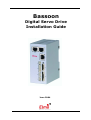
Bassoon Digital Servo Drive Installation Guide June 2004 Notice This guide is delivered subject to the following conditions and restrictions: This guide contains proprietary information belonging to Elmo Motion Control Ltd. Such information is supplied solely for the purpose of assisting users of the Bassoon servo drive in its installation. The text and graphics included in this manual are for the purpose of illustration and reference only. The specifications on which they are based are subject to change without notice. Elmo Motion Control and the Elmo Motion Control logo are trademarks of Elmo Motion Control Ltd. Information in this document is subject to change without notice. Document No. MAN-BASIG Copyright 2004 Elmo Motion Control Ltd. All rights reserved. Bassoon Catalog Number: BAS-AX/230I Version: Blank = Standard A = Advanced Continuous Current (Amps) Nominal AC Operating Voltage Feedback: Blank = Incremental Encoder and/or Halls R = Resolver I = Interpolated Analog Encoder Cable Kit Catalog Number HAR-CABLEKIT (kit available upon request) Related Document MAN-CABLEKIT (available on our website) Revision History: Ver. 1.0 June 2004 Elmo Motion Control Inc. 1 Park Drive, Suite 12 Westford, MA 01886 USA Tel: +1 (978) 399-0034 Fax: +1 (978) 399-0035 (MAN-BASIG.pdf) Initial Release Elmo Motion Control GmbH Steinbeisstrasse 41 D-78056, Villingen-Schwenningen Germany Tel: +49 (07720) 8577-60 Fax: +49 (07720) 8577-70 www.elmomc.com Bassoon Installation Guide MAN-BASIG (Ver 1.0) Contents Chapter 1: Safety Information............................................................................................... 1-1 1.1 1.2 1.3 1.4 1.5 Warnings .............................................................................................................. 1-2 Cautions................................................................................................................ 1-2 Directives and Standards .................................................................................... 1-3 CE Mark Conformance........................................................................................ 1-3 Warranty Information ......................................................................................... 1-3 Chapter 2: Introduction .......................................................................................................... 2-1 2.1 Drive Description ................................................................................................ 2-1 2.2 Product Features.................................................................................................. 2-1 2.2.1 Current Control..............................................................................................2-1 2.2.2 Velocity Control .............................................................................................2-1 2.2.3 Position Control .............................................................................................2-2 2.2.4 Advanced Position Control (in Advanced model only) ...............................2-2 2.2.5 Communication Options ..............................................................................2-2 2.2.6 Feedback Options ..........................................................................................2-2 2.2.7 Fault Protection..............................................................................................2-3 2.3 System Architecture ............................................................................................ 2-3 2.4 How to Use this Guide........................................................................................ 2-4 Chapter 3: Installation ............................................................................................................ 3-1 3.1 Before You Begin ................................................................................................. 3-1 3.1.1 Site Requirements ..........................................................................................3-1 3.1.2 Hardware Requirements ..............................................................................3-1 3.1.3 AC Power Requirements ..............................................................................3-3 3.2 Unpacking the Drive Components .................................................................... 3-3 3.3 Assembling the Heatsink .................................................................................... 3-4 3.4 Mounting the Bassoon......................................................................................... 3-4 3.4.1 Mounting on a DIN Rail ...............................................................................3-4 3.4.2 Mounting Directly onto a Wall ....................................................................3-5 3.5 Connecting the Cables......................................................................................... 3-5 3.5.1 Wiring the Bassoon........................................................................................3-5 3.5.2 Connecting the Power Cables ......................................................................3-8 3.5.2.1 Connecting the Motor Cable..................................................... 3-8 3.5.2.2 Connecting the Main Power Cable........................................... 3-9 3.5.3 Connecting the Auxiliary Power Cable (J4) .............................................3-10 3.5.4 Feedback and Control Cable Assemblies .................................................3-11 3.5.5 Main Feedback Cable (Port J3)...................................................................3-12 3.5.6 Main and Auxiliary Feedback Combinations..........................................3-15 3.5.6.1 Auxiliary Feedback - Buffered or Emulated Output............ 3-16 3.5.6.2 Auxiliary Feedback - Differential Encoder Input Option .... 3-17 3.5.6.3 Auxiliary Feedback - Single-Ended Encoder Input.............. 3-18 3.5.6.4 Auxiliary Feedback – Pulse & Direction Input ..................... 3-19 3.5.7 I/O Cables ....................................................................................................3-20 3.5.7.1 Digital Input (Port J5) .............................................................. 3-20 3.5.7.2 Digital Output (Port J6) ........................................................... 3-22 3.5.7.3 Analog Input (Port J7) ............................................................. 3-23 Bassoon Installation Guide Contents MAN-BASIG (Ver 1.0) 3.5.8 Communication Cable (Port J1, J8, J9) ......................................................3-24 3.5.8.1 RS-232 Communication ........................................................... 3-24 3.5.8.2 CANopen Communication ..................................................... 3-25 3.6 Powering Up ...................................................................................................... 3-27 3.7 Initializing the System....................................................................................... 3-27 Appendix: Technical Specifications.................................................................................... A-1 A.1 Features................................................................................................................ A-1 A.1.1 Motion Control Modes................................................................................ A-1 A.1.2 Advanced Positioning Motion Control Modes ....................................... A-1 A.1.3 Advanced Filters and Gain Scheduling.................................................... A-1 A.1.4 Fully Programmable.................................................................................... A-1 A.1.5 Feedback Options ........................................................................................ A-1 A.1.6 Input/Output ............................................................................................... A-2 A.1.7 Built-In Protection........................................................................................ A-2 A.2 Bassoon Dimensions........................................................................................... A-3 A.3 General Specifications ........................................................................................ A-4 A.4 Environmental Conditions ................................................................................ A-4 A.5 Bassoon Connectors............................................................................................ A-5 A.5.1 Connector Types .......................................................................................... A-5 A.5.2 Control and Feedback Connector Specifications..................................... A-5 A.6 Auxiliary Power Supply (J4).............................................................................. A-6 A.7 Control Specifications ........................................................................................ A-6 A.7.1 Current Loop ................................................................................................ A-6 A.7.2 Velocity Loop ............................................................................................... A-7 A.7.3 Position Loop ............................................................................................... A-7 A.8 Feedback .............................................................................................................. A-8 A.8.1 Feedback Supply Voltage ........................................................................... A-8 A.8.2 Incremental Encoder ................................................................................... A-8 A.8.3 Digital Halls.................................................................................................. A-9 A.8.4 Interpolated Analog Encoder (Sine/Cosine) ........................................... A-9 A.8.5 Resolver....................................................................................................... A-10 A.8.6 Encoder Outputs........................................................................................ A-10 A.9 I/O’s ................................................................................................................. A-11 A.9.1 Digital Input Interfaces ............................................................................. A-11 A.9.2 Digital Output Interface............................................................................ A-12 A.9.3 Analog Input (J7) ....................................................................................... A-13 A.10 Communications.............................................................................................. A-13 A.11 Pulse Width Modulation (PWM) ................................................................... A-14 A.12 Heatsink Specifications ................................................................................... A-14 A.13 Standards Compliance .................................................................................... A-15 A.13.1 Quality Assurance ................................................................................. A-15 A.13.2 Design...................................................................................................... A-15 A.13.3 Safety ....................................................................................................... A-16 A.13.4 EMC ......................................................................................................... A-16 A.13.5 Workmanship......................................................................................... A-16 A.13.6 PCB .......................................................................................................... A-16 A.13.7 Packing .................................................................................................... A-16 Index...........................................................................................................................................I-1 ii Bassoon Installation Guide MAN-BASIG (Ver 1.0) Chapter 1: Safety Information In order to achieve the optimum, safe operation of the Bassoon servo drive, it is imperative that you implement the safety procedures included in this installation guide. This information is provided to protect you and to keep your work area safe when operating the Bassoon and accompanying equipment. Please read this chapter carefully before you begin the installation process. Before you start, ensure that all system components are connected to earth ground. Electrical safety is provided through a low-resistance earth connection. Only qualified personnel may install, adjust, maintain and repair the servo drive. A “qualified person” has the knowledge and authorization to perform tasks such as transporting, assembling, installing, commissioning and operating motors. The Bassoon servo drive contains electrostatic-sensitive components that can be damaged if handled incorrectly. To prevent any electrostatic damage, avoid contact with highly insulating materials, such as plastic film and synthetic fabrics. Place the product on a conductive surface and ground yourself in order to discharge any possible static electricity build-up. To avoid any potential hazards that may cause severe personal injury or damage to the product during operation, keep all covers and cabinet doors shut. The following safety symbols are used in this manual: Warning: This information is needed to avoid a safety hazard, which might cause bodily injury. Caution: This information is necessary for preventing damage to the product or to other equipment. Note: This is auxiliary information that ensures the correct operation of the equipment. 1-1 Bassoon Installation Guide Safety Information MAN-BASIG (Ver 1.0) 1.1 Warnings To avoid electric arcing and hazards to personnel and electrical contacts, never connect/disconnect the servo drive while the power source is on. Power cables can carry a high voltage, even when the motor is not in motion. Disconnect the Bassoon from all voltage sources before it is opened for servicing. The Bassoon servo drive contains grounding conduits for electric current protection. Any disruption to these conduits may cause the device to become “hot” (live) and dangerous. After shutting off the power and removing the power source from your equipment, wait at least 1 minute before touching or disconnecting parts of the equipment that are normally loaded with electrical charges (such as capacitors or contacts). Measuring the electrical contact points with a meter before touching the equipment is recommended. 1.2 Cautions The Bassoon servo drive contains hot surfaces and electrically-charged components during operation. The maximum AC power supply connected to the instrument must comply with the parameters outlined in this guide. The Bassoon drive must be connected to an approved 24VDC auxiliary power supply through a line that is separated from hazardous line voltages using reinforced or double insulation in accordance with approved safety standards. The Bassoon X/230 series is designed to gets its power from a 30 ~ 255 VAC single phase power source. It can be connected directly to the line voltage. An isolation transformer is not needed. Before switching on the Bassoon, verify that all safety precautions have been observed and that the installation procedures in this manual have been followed. 1-2 Bassoon Installation Guide Safety Information MAN-BASIG (Ver 1.0) 1.3 1-3 Directives and Standards The Bassoon conforms to the following industry safety standards: Safety Standard Item In compliance with UL508c and UL840 Conformance to the following safety standards: Power Conversion Equipment Insulation Coordination, Including Clearance and Creepage Distances of Electrical Equipment In compliance with UL60950 (formerly UL1950) Safety of Information Technology Equipment, Including Electrical Business Equipment In compliance with EN60204-1 Low Voltage Directive, 73/23/EEC The Bassoon servo drive has been developed, produced, tested and documented in accordance with the relevant standards. Elmo Motion Control is not responsible for any deviation from the configuration and installation described in this documentation. Furthermore, Elmo is not responsible for the performance of new measurements or ensuring that regulatory requirements are met. 1.4 CE Mark Conformance The Bassoon servo drive is intended for incorporation in a machine or end product. The actual end product must comply with all safety aspects of the relevant requirements of the European Safety of Machinery Directive 98/37/EC as amended, and with those of the most recent versions of standards EN60204-1 and EN292-2 at the least. According to Annex III of Article 13 of Council Directive 93/68/EEC, amending Council Directive 73/23/EEC concerning electrical equipment designed for use within certain voltage limits, the Bassoon meets the provisions outlined in Council Directive 73/23/EEC. The party responsible for ensuring that the equipment meet the limits required by EMC regulations is the manufacturer of the end product. 1.5 Warranty Information The products covered in this manual are warranted to be free of defects in material and workmanship and conform to the specifications stated either within this document or in the product catalog description. All Elmo drives are warranted for a period of 12 months from the time of installation, or 18 months from time of shipment, whichever comes first. No other warranties, expressed or implied — and including a warranty of merchantability and fitness for a particular purpose — extend beyond this warranty. Bassoon Installation Guide MAN-BASIG (Ver 1.0) Chapter 2: Introduction This installation guide describes the Bassoon servo drive and the steps for its wiring, installation and powering up. Following these guidelines ensures maximum functionality of the drive and the system to which it is connected. 2.1 Drive Description The Bassoon is a powerful servo drive that operates in digital current, velocity, position and advanced position modes, in conjunction with a permanent-magnet synchronous brushless motor or DC brush motor. The Bassoon features flexible sinusoidal and trapezoidal commutation, with vector control. The Bassoon can operate as a stand-alone device or as part of a multi-axis network in a distributed configuration. The Bassoon drive is set up and tuned using Elmo’s Composer software. This Windowsbased application enables users to quickly and simply configure the servo drive for optimal use with their motor. The Bassoon connects directly to 110/230 VAC single-phase power source. A separate 24 VDC power supply serves as both the auxiliary supply and the backup supply. This allows a safe and economical "power backup" feature that is essential for positioning systems. Two variations of the Bassoon are available: the Standard version and the Advanced version, which features advanced positioning capabilities. Both versions operate with RS-232 and/or CANopen communications. 2.2 Product Features 2.2.1 Current Control Fully digital Sinusoidal commutation with vector control or trapezoidal commutation with resolver, encoder and/or digital Hall sensors 12-bit current loop resolution Automatic gain scheduling, to compensate for variations in the DC bus power supply 2.2.2 Velocity Control Fully digital Programmable PI and FFW (feed forward) control filters Sample rate two times current loop sample time “On-the-fly” gain scheduling Automatic, manual and advanced manual tuning and determination of optimal gain and phase margins 2-1 Bassoon Installation Guide Introduction MAN-BASIG (Ver 1.0) 2.2.3 Position Control Programmable PIP control filter Programmable notch and low-pass filters Position follower mode for monitoring the motion of the slave axis relative to a master axis, via an auxiliary encoder input Pulse-and-direction inputs Sample rate four times current loop sample time Fast event capturing inputs 2.2.4 Advanced Position Control (in Advanced model only) Position-based and time-based ECAM mode that supports a non-linear follower mode, in which the motor tracks the master motion using an ECAM table stored in flash memory PT and PVT motion modes Dual (position/velocity) loop Fast output compare (OC) 2.2.5 Communication Options Depending on the application, Bassoon users can select from two communication options: RS-232 serial communication CANopen for fast communication in a multi-axis distributed environment 2.2.6 Feedback Options Incremental Encoder – up to 20 Mega-Counts (5 Mega-Pulse) per second Digital Halls – up to 2 KHz Incremental Encoder with Digital Halls for commutation – up to 20 Mega-Counts per second for encoder Absolute Encoder Interpolated Analog Sine/Cosine Encoder – up to 250 KHz (analog signal) • Internal Interpolation – programmable up to X4096 • Automatic Correction of: ♦ amplitude mismatch ♦ phase mismatch ♦ signals offset • Encoder outputs, buffered, differential Resolver • Programmable 10~15 bit resolution • Up to 512 Revolution Per Second (RPS) • Encoder outputs, buffered, differential Elmo drives provide supply voltage for all the feedback options 2-2 Bassoon Installation Guide Introduction MAN-BASIG (Ver 1.0) 2.2.7 Fault Protection The Bassoon includes built-in protection against possible fault conditions, including: Software error handling Status reporting for a large number of possible fault conditions Protection against conditions such as excessive temperature, under/over voltage, loss of commutation signal, short circuits between the motor power outputs and between each output and power input return Recovery from loss of commutation signals and from communication errors 2.3 System Architecture Communication RS 232 and CANopen Analog Encoder or Resolver or Main Encoder I/Os Controller SMPS Auxiliary Encoder Protection PWM Current Feedback Power Stage Figure 2-1 Bassoon System Block Diagram Emulated Output 24 VDC 2-3 Bassoon Installation Guide Introduction MAN-BASIG (Ver 1.0) 2.4 How to Use this Guide In order to install and operate your Elmo Bassoon servo drive, you will use this manual in conjunction with a set of Elmo documentation. Installation is your first step; after carefully reading the safety instructions in the first chapter, the following chapters provide you with installation instructions as follows: Chapter 3, Installation, provides step-by-step instructions for unpacking, mounting, connecting and powering up the Bassoon. The Appendix, Technical Specifications, lists all the drive ratings and specifications. Upon completing the instructions in this guide, your Bassoon servo drive should be successfully mounted and installed. From this stage, you need to consult higher-level Elmo documentation in order to set up and fine-tune the system for optimal operation. The following figure describes the accompanying documentation that you will require. CANopen Implementation Guide SimplIQ Software Manual SimplIQ Command Reference Manual Programming Composer User Manual Setup Installation Digital Servo Drive Cable Kit Bassoon Installation Guide Figure 2-2: Elmo Documentation Hierarchy As depicted in the previous figure, this installation guide is an integral part of the Bassoon documentation set, comprising: The Composer Software Manual, which includes explanations of all the software tools that are part of Elmo’s Composer software environment. The SimplIQ Command Reference Manual, which describes, in detail, each software command used to manipulate the Bassoon motion controller. The SimplIQ Software Manual, which describes the comprehensive software used with the Bassoon. 2-4 Bassoon Installation Guide 3-1 MAN-BASIG (Ver 1.0) Chapter 3: Installation 3.1 Before You Begin 3.1.1 Site Requirements You can guarantee the safe operation of the Bassoon by ensuring that it is installed in an appropriate environment. Feature Value Ambient operating temperature 0° to 40°C (32° to 113°F) Maximum operating altitude 10,000 m (30,000 ft) Maximum relative humidity 90% non-condensing Operating area atmosphere No flammable gases or vapors permitted in area Models for extended environmental conditions are available. The Bassoon dissipates its heat by natural convection. The maximum operating ambient temperature of 0 to 40° C (32 to 104° F) must not be exceeded. 3.1.2 Hardware Requirements The components that you will need to install your Bassoon are: Described in Section Component Connector Main Power Cable Power Connector 3.5.2.2 Motor Cable Power Connector 3.5.2.2 J4 3.5.3 Auxiliary Power Cable Diagram Bassoon Installation Guide Installation MAN-BASIG (Ver 1.0) Connector Described in Section Main Feedback Cable J3 3.5.5 Auxiliary Feedback (if needed) J2 3.5.6 Digital Input Cable (if needed) J5 3.5.6 Digital Output Cable (if needed) J6 3.5.6 J1, J8, J9 3.5.8 Component Communication Cables (RS-232 and/or CANopen) Diagram 1 PC for drive setup and tuning Motor data sheet or manual 3-2 Bassoon Installation Guide Installation MAN-BASIG (Ver 1.0) 3.1.3 3-3 AC Power Requirements Below are the Bassoon’s AC power requirements: Component Single-Phase Supply Voltage Circuit breaker current rating 200% ~ 300% of drive current Circuit breaker voltage rating 230 VAC Contactor Up to 200% of drive current 3.2 Unpacking the Drive Components Before you begin working with the Bassoon system, verify that you have all of its components, as follows: The Bassoon servo drive The Composer software and software manual The Bassoon cable kit (if ordered separately) The Bassoon is shipped in a cardboard box with styrofoam protection. To unpack the Bassoon: 1. Carefully remove the servo drive from the box and the Styrofoam. 2. Check the drive to ensure that there is no visible damage to the instrument. If any damage has occurred, report it immediately to the carrier that delivered your drive. 3. To ensure that the Bassoon you have unpacked is the appropriate type for your requirements, locate the part number sticker on the side of the Bassoon. It looks like this: The P/N number at the top gives the type designation as follows: BAS-A1/230I Version: Blank = Standard A = Advanced Continuous Current (Amps) Nominal AC Operating Voltage Feedback: Blank = Incremental Encoder and/or Halls R = Resolver I = Interpolated Analog Encoder 4. Verify that the Bassoon type is the one that you ordered. Bassoon Installation Guide Installation MAN-BASIG (Ver 1.0) 3.3 3-4 Assembling the Heatsink When an external heatsink device is required, attach it with four screws to the left side of the Bassoon, as depicted in the following diagrams. BAS0033A BAS0041A-DWG Figure 3-1: Attaching the Heatsink To mount the finned heatsink use M4 screws and spring washers. To mount the L-shaped heatsink use conical head M4 screws. 3.4 Mounting the Bassoon The Bassoon has been designed for two standard mounting options: Mounting on a DIN rail Attaching directly to the wall with screws 3.4.1 Mounting on a DIN Rail At the top rear of the Bassoon, a horizontal groove lets you quickly and easily snap the drive onto a DIN rail in your work area. To mount the Bassoon on a DIN rail: 1. If the mounting tab is attached to the top of the Bassoon, remove it by pushing it down and slipping it out of the slot (see the figure below). 2. Mount the upper slit on the back of the Bassoon on the upper edge of the DIN rail. 3. Tilt the bottom of the Bassoon towards the bottom of the DIN rail until you hear a click. Figure 3-2: Mounting the Bassoon on a on DIN Rail Bassoon Installation Guide Installation MAN-BASIG (Ver 1.0) 3.4.2 3-5 Mounting Directly onto a Wall The mounting strips at the back of the Bassoon enables it to be screwed directly into a wall. If it is not already assembled in the upper slot in the back of the Bassoon, assemble the upper mounting tab now. To mount the Bassoon onto a wall: 1. On the back of the drive, fully extend the top mounting strip so that the end with the holes are exposed. (The bottom strip is delivered already extended.) 2. Mount the Bassoon vertically onto the wall with two M4 round head screws and washers, one through the top hole of the mounting strip and one at the bottom. Figure 3-3: Extending the Mounting Strips and Attaching the Screws 3.5 Connecting the Cables 3.5.1 Wiring the Bassoon Once the Bassoon is mounted, you are ready to wire the device. Proper wiring, grounding and shielding are essential for ensuring safe, immune and optimal servo performance of the Bassoon. Follow these instructions to ensure safe and proper wiring: Use twisted-pair shielded wires for control, feedback and communication ports. For best results, use an aluminum foil shield covered by copper braid with a drain wire. The drain wire is a non-insulated wire that is in contact with parts of the cable, usually the shield. It is used to terminate the shield and as a grounding connection. The impedance of the wire must be as low as possible. The size of the wire must be thicker than actually required by the carrying current. 24 or 26 AWG wire for control and feedback cables is satisfactory. Bassoon Installation Guide Installation MAN-BASIG (Ver 1.0) 3-6 Use shielded wires for motor connections as well. If the wires are long, ensure that the capacitance between the wires is not too high: C < 30 nF is satisfactory for most applications. Keep all wires and cables as short as possible. Keep the motor wires as far away as possible from the feedback, control and communication cables. Ensure that in normal operating conditions, the shielded wires and drain carry no current. The only time these conductors carry current is under abnormal conditions, when electrical equipment has become a potential shock or fire hazard while conducting external EMI interferences directly to ground, in order to prevent them from affecting the drive. Failing to meet this requirement can result in drive/controller/host failure. After completing the wiring, carefully inspect all wires to ensure that the crimp terminals are firmly attached to the wire ends and that the wires are firmly connected to their connectors. The following connectors are used for wiring the Bassoon. Type Function Port Connector Location 8-pin RJ-45 CANopen J8 8-pin RJ-45 CANopen J9 8-pin RJ-45 RS-232 J1 8-pin Molex Auxiliary Feedback J2 12-pin Molex Main Feedback J3 Auxiliary Power Supply 2-pin Molex Auxiliary power supply J4 Digital Input Auxiliary Feedback 8-pin Molex Digital input J5 Digital Output Main Feedback 4-pin Molex Digital output J6 Analog Input 3-pin Molex Analog input J7 Main Power 7-pin Phoenix Main power Power CANopen CANopen RS232 Table 3-1: Bassoon Connectors Bassoon Installation Guide Installation MAN-BASIG (Ver 1.0) Bassoon PC RS232 RS-232 J1 CANopen J8 CAN_H CAN Controller Tx CAN_L Drain wire / Shield 3-7 Rx CAN_GND COMRET CAN_SHLD Drain Wire / Shield CAN_H Bassoon CAN_L Drain wire / Shield CAN_GND CAN_SHLD CANopen J9 Feedback B J2 Controller Feedback A Main Feedback J3 J5 IN1 IN2 4 Drain Wire / Shield IN3 IN4 M3 M Power Connector IN5 M2 IN6 M1 INRET PE INRET J6 PE OUT1 AC2 OUTRET1 AC1 OUT2 OUTRET2 AUX. SUPPLY 24VDC J4 +24v J7 ANALIN1 + ANALIN1 + ANALIN1 - ANALIN1 - ANLRET Isolated Transformer ANLRET BAS0010A Figure 3-4: Bassoon Detailed Connection Diagram Bassoon Installation Guide Installation MAN-BASIG (Ver 1.0) 3.5.2 3-8 Connecting the Power Cables The main power connector located at the bottom of the Bassoon, as follows: Pin Function Cable AC1 Main Voltage Phase 1 Power AC2 Main Voltage Phase 2 Power Pin Positons PE M1 PE PE Protective earth Power AC Motor Cable DC Motor Cable PE Protective earth Motor Motor M1 Motor phase Motor N/C M2 Motor phase Motor Motor M3 Motor phase Motor Motor M2 M3 AC2 AC1 When connecting several motors, all must be wired in an identical manner. Table 3-2: Connector for Main Power and Motor Cables 3.5.2.1 Connecting the Motor Cable Connect the motor power cable to the M1, M2, M3 and PE terminals of the main power connector. The phase connection order is arbitrary because the Composer will establish the proper commutation automatically during setup. However, if you plan to copy the set-up to other drives, then the phase order on all copy drives must be the same. Notes for connecting the motor cables: For best immunity, it is highly recommended to use a shielded (not twisted) cable for the motor connection. A 4-wire shielded cable should be used. The gauge is determined by the actual current consumption of the motor. Connect the shield of the cable to the closest ground connection at the motor end. The forth wire should be used for the ground connection between the motor and the second PE terminal of the Bassoon. Be sure that the motor chassis is properly grounded. Figure 3-5: AC Motor Power Connection Diagram Bassoon Installation Guide Installation MAN-BASIG (Ver 1.0) 3.5.2.2 3-9 Connecting the Main Power Cable Connect the main power supply cable to the AC1, AC2 and PE terminals of the main power connector. Notes for connecting the AC power cable: For best immunity, a shielded (not twisted) cable is recommended (not mandatory) for the AC power supply cable. A 3-wire shielded cable should be used. The gauge is determined by the actual current consumption of the motor. Connect the two power wires (Neutral and Phase) to the AC power leads of the source. For safety requirements, the third wire must be used for the protective earth connection (connected to the PE terminal). Figure 3-6: Main Power Supply Connection Diagram Bassoon Installation Guide Installation MAN-BASIG (Ver 1.0) 3.5.3 3-10 Connecting the Auxiliary Power Cable (J4) Connect the auxiliary power supply to the J4 port on the front of the Bassoon, using a 2-pin Molex plug. Remember, you are working with DC power; be sure to exercise caution. The required voltage is 24 VDC. Notes for 24 VDC auxiliary power supply connections: Use a 24 or 26 AWG twisted pair shielded cable. The 24 VDC auxiliary power supply must meet all safety requirements and must be separated from hazardous live voltages using reinforced or double insulation in accordance with approved safety standards. For safety reasons, connect the return (common) of the 24 VDC source to the closest ground. Connect the cable shield to the closest ground near the 24 VDC source. Before applying power, first verify the polarity of the connection. Pin Signal Function 1 +24VDC +24 VDC auxiliary power supply 2 RET24VDC Return (common) of the 24 VDC auxiliary power supply Pin Position Table 3-3: Auxiliary Power Cable Plug Figure 3-7: Auxiliary Power Supply (J4) Connection Diagram Bassoon Installation Guide Installation MAN-BASIG (Ver 1.0) 3.5.4 3-11 Feedback and Control Cable Assemblies The Auxiliary Power Cable (J4), the Feedback cables (J2 and J3) and the I/O cables (J5, J6 and J7) all use 2 mm pitch Molex “Sherlock” connectors. These connectors snap together quite easily, but require a small standard screwdriver for disassembly. To disassemble the Molex connector simply (1) slip the screwdriver into the lock (this will cause the lock to disengage) and (2) twist the screwdriver downward with light pressure on the handle (see the figure below). Figure 3-8 Disconnecting Molex Connectors Notes for assembling Feedback and Control cable assemblies: Use 24 or 26 AWG twisted-pair shielded cables. On the motor side connections, ground the shield to the motor chassis. On controller side connections, follow the controller manufacturer’s recommendations concerning shield and/or drain wire connections. Bassoon Installation Guide Installation MAN-BASIG (Ver 1.0) 3.5.5 3-12 Main Feedback Cable (Port J3) The main feedback cable is used to transfer feedback data from the motor to the drive. The Bassoon accepts the following as a main feedback mechanism: Incremental encoder only Incremental encoder with digital Hall sensors Digital Hall sensors only Incremental Analog (Sine/Cosine) encoder (option) Resolver (option) Connect the main feedback cable from the motor to the J3 port on the front of the Bassoon, using a 12-pin, Molex plug. Connect the drain wire to pin 4. If the cable has no drain wire, connect the shield to pin 4. Ground the shield to the motor chasis. Drain Wire or Shield Figure 3-9: The Main Feedback (J3) Cable The wiring of the Main Feedback cable depends on the type of device used. Incremental Encoder wiring, Interpolated Analog Encoder wiring and Resolver wiring are shown in the table below. Bassoon Installation Guide Installation MAN-BASIG (Ver 1.0) Incremental Encoder Interpolated Analog (Sine/Cosine) Encoder Resolver BAS X/230_ BAS X/230I BAS XX/230R Pin Signal Function Signal Function Signal 3-13 Function 1 HC Hall sensor C input NC - NC - 2 HB Hall sensor B input NC - NC - 3 HA Hall sensor A input NC - NC - 4 SUPRET Supply return SUPRET Supply return SUPRET Supply return 5 SUPRET Supply return SUPRET Supply return SUPRET Supply return 6 +5V Encoder/Hall +5 V supply +5V Encoder/Hall +5 V supply NC - 7 INDEX- Index complement R- Reference complement R2 Vref complement f= 1/TS, 50mA Maximum 8 INDEX Index R+ Reference R1 Vref f=1/TS, 50mA Max. 9 CHB- Channel B cmplmnt B- Cosine B complement S4 Cosine B complement 10 CHB Channel B B+ Cosine B S2 Cosine B 11 CHA- Channel A cmplmnt A- Sine A complement S3 Sine A complement 12 CHA Channel A A+ Sine A S1 Sine A Table 3-4: Main Feedback Cable Pin Assignments Feedback A - J3 1 HC HB CHA CHA- Hall C 2 Hall B 12 CHA 11 CHA- 10 CHB CHB Bassoon 9 CHB- CHBINDEX 8 INDEX 7 INDEX- INDEXHA Incremental Encoder with Hall Sensor 3 Hall A 6 +5v Encoder / Hall +5v Supply SUPRET 5 SUPRET 4 Hall / Encoder Supply / Voltage Return Drain Wire / Shield BAS0015A Figure 3-10: Main Feedback- Incremental Encoder Connection Diagram Bassoon Installation Guide Installation MAN-BASIG (Ver 1.0) Bassoon Feedback A - J3 3-14 Sine / Cosine Encoder 12 A+ A+ 11 A- A- 10 B+ B+ 9 B- B8 R+ R+ 7 R- R6 Encoder +5v Supply +5v SUPRET 5 SUPRET 4 Encoder Supply Return Drain Wire / Shield BAS0016A Figure 3-11: Main Feedback – Interpolated Analog Encoder Connection Diagram Bassoon Feedback A - J3 Resolver 12 S1 S3 S1 11 S3 10 S2 S2 9 S4 S4 8 R1 R1 7 R2 R2 SUPRET 5 SUPRET 4 Drain Wire / Shield BAS0017A Figure 3-12: Main Feedback – Resolver Connection Diagram Bassoon Installation Guide Installation MAN-BASIG (Ver 1.0) 3.5.6 3-15 Main and Auxiliary Feedback Combinations The Main Feedback is always used in motion control devices whereas Auxiliary Feedback is often, but not always used. The Auxiliary Feedback port “FEEDBACK B” (J2) can be used in combination with the Main Feedback port, “FEEDBACK A” (J3). Feedback B can be set by software as follows: FEEDBACK A (J3) FEEDBACK B (J2) YA[4] = 4 YA[4] = 2 YA[4] = 0 B - output Incremental Encoder Input Differential and Buffered Main Encoder Signal A - input Incremental Encoder B - output Interpolated Analog (Sin/Cos) Encoder Input Analog Encoder Position Data Emulated in Incremental Encoder Format A - input Analog Encoder (signals are quadrature, differential & buffered) A - input Incremental Encoder or Analog Encoder or Resolver B - input Differential or Singleended Auxiliary Incremental Encoder A - input Incremental Encoder or Analog Encoder or Resolver B - input Differential or Singleended Pulse & Direction Commands B - output Resolver Position Data Emulated in Incremental Encoder Format Resolver Input A - input Resolver Typical Applications (signals are quadrature, differential & buffered) Any application where the main encoder is used, not only for the drive, but also for other purposes such as position controllers and/or other drives. Analog Encoder applications where position data is required in the Encoder’s quadrature format. Resolver applications where position data is required in the Encoder’s quadrature format. Any application where two feedbacks are used by the drive. Port B serves as an input for the auxiliary incremental encoder (differential or singleended). For applications such as Follower, ECAM, or Dual Loop. Port B serves as an input for Pulse & Direction commands (differential or single-ended). Table 3-5: Main Feedback –Auxiliary Feedback Combinations Bassoon Installation Guide Installation MAN-BASIG (Ver 1.0) 3.5.6.1 3-16 Main Encoder Buffered Outputs or Emulated Encoder Outputs Option on FEEDBACK B (J2) (YA[4]=4) Through FEEDBACK B the Bassoon can provide buffered main, or emulated, encoder signals to another controller or drive. This option can be used when: The Bassoon is used as a current amplifier to provide position data to the position controller. The Bassoon is used in velocity mode, to provide position data to the position controller. The Bassoon is used as a master in Follower or ECAM mode. Below are the signals on the Auxiliary Feedback ports when set up to run as a buffered outputs or emulated outputs of the main encoder (on FEEDBACK A): Pin Signal Function Pin Position 1 SUPRET Supply return 2 +5 V NA 3 INDEXO- Index complement output 4 INDEXO Index output 5 CHBO- Channel B complement output 6 CHBO Channel B output 7 CHAO- Channel A complement output 8 CHAO Channel A output Table 3-6: Main Encoder Buffered Output or Emulated Encoder Output Pin Assignments on J2 Feedback B - J2 SUPRET +5v Controller 1 2 3 INDEX- INDEXO- Bassoon 4 INDEX INDEXO 5 CHB- CHBO6 CHB CHBO 7 CHA- CHAO8 CHAO CHA BAS0023A Figure 3-13: Main Encoder Buffered Output or Emulated Encoder Output on J2 - Connection Diagram Bassoon Installation Guide Installation MAN-BASIG (Ver 1.0) 3.5.6.2 3-17 Differential Auxiliary Encoder Input Option on FEEDBACK B (J2) (YA[4]=2) The Bassoon can be used as a slave by receiving the position (on Port B) of the master encoder data in Follower or ECAM mode Below are the signals on the Auxiliary Feedback port when set up to run as a differential auxiliary encoder input: Pin Signal Function 1 SUPRET Supply return 2 +5 V Encoder + 5 V supply voltage, 5 V @ 200 mA 3 INDEX- Auxiliary index low input 4 INDEX Auxiliary index high input 5 CHB- Auxiliary channel B low input 6 CHB Auxiliary channel B high input 7 CHA- Auxiliary channel A low input 8 CHA Auxiliary channel A high input Pin Position Table 3-7: Differential Auxiliary Encoder Input Pin Assignments on J2 Feedback B - J2 SUPRET +5v Encoder 1 Encoder supply voltage return 2 2 Encoder +5v Supply 3 INDEX- Bassoon INDEX4 INDEX INDEX 5 CHB- CHB6 CHB CHB 7 CHA- CHA8 CHA CHA BAS0024A Figure 3-14: Differential Auxiliary Encoder Inputs on J2 - Connection Diagram Bassoon Installation Guide Installation MAN-BASIG (Ver 1.0) 3.5.6.3 Single-ended Auxiliary Input Option on FEEDBACK B (J2) (YA[4]=2) The Bassoon can be used as a slave by receiving the position data (on Port B) of the master encoder in Follower or ECAM mode. Below are the signals on the Auxiliary Feedback port when set up to run as a single-ended auxiliary input: Signal Function 1 SUPRET Supply return 2 +5 V Encoder/Hall +5 V supply voltage, 5 V @ 200 mA 3 — — 4 INDEX Index 5 — — 6 CHB Channel B 7 — — 8 CHA Channel A Pin Position Table 3-8: Single-ended Auxiliary Encoder Input Pin Assignments on J2 Encoder Feedback B - J2 SUPRET +5v 1 1 2 2 2 Supply Voltage Return +5v 3 Bassoon Pin 4 4 INDEX INDEX 5 6 6 CHB CHB 7 8 CHA 8 CHA BAS0025A Figure 3-15: Single-ended Auxiliary Encoder inputs on J2 - Connection Diagram 3-18 Bassoon Installation Guide Installation MAN-BASIG (Ver 1.0) 3.5.6.4 3-19 Pulse-and-Direction Input Option on FEEDBACK B (J2) (YA[4]=0) This mode is used for input of differential or single-ended pulse-and-direction position commands. Below are the signals on the Auxiliary Feedback ports when set up to run as a single-ended pulse-and-direction input: Pin Signal Function 1 SUPRET Supply return 2 +5 V NA 3 — — 4 — — 5 — — 6 DIR/CHB Direction input (push/pull 5 V or open collector) 7 — — 8 PULS/CHA Pulse input (push/pull 5 V or open collector) Pin Position Table 3-9: Pulse-and-Direction Auxiliary Encoder Pin Assignments on J2 Controller Feedback B - J2 SUPRET 1 1 Supply Voltage Return 2 3 Bassoon 4 5 6 DIR / CHB DIRECTION 7 8 PULS / CHA PULSE BAS0026A Figure 3-16: Pulse-and-Direction Auxiliary Encoder Pins on J2 - Connection Diagram Bassoon Installation Guide Installation MAN-BASIG (Ver 1.0) 3.5.7 3-20 I/O Cables The following table lists the I/O cables that you should connect according to your specific requirements: 3.5.7.1 I/O Description Total Port Digital input 6 J5 Digital output 2 J6 Analog input 1 J7 Digital Input (Port J5) Notes for connecting the digital input cable: Use 24 or 26 AWG twisted pair shielded cable. Connect the cable shield to the ground near the signal source (controller) according to the manufacturer’s recommendations. Pin Signal Function 1 IN1 Programmable input 1 (general purpose, RLS, FLS, INH) 2 IN2 Programmable input 2 (general purpose, RLS, FLS, INH) 3 IN3 Programmable input 3 (general purpose, RLS, FLS, INH) 4 IN4 Programmable input 4 (general purpose, RLS, FLS, INH) 5 IN5 Programmable input 5 (event capture, Main Home, general purpose, RLS, FLS, INH) 6 IN6 Programmable input 6 (event capture, Auxiliary Home, general purpose, RLS, FLS, INH) 7 INRET Programmable input return 8 INRET Programmable input return Pin Position Table 3-10: Digital Input Cable Pin Assignments Bassoon Installation Guide Installation MAN-BASIG (Ver 1.0) Figure 3-17: Digital Input Connection Diagram 3-21 Bassoon Installation Guide Installation MAN-BASIG (Ver 1.0) 3.5.7.2 Digital Output (Port J6) Notes for connecting the digital output cable: Use 24 or 26 AWG twisted pair shielded cable. Connect the cable shield to the ground near the controller according to the manufacturer’s recommendations. Pin Signal Function 1 OUT1 Programmable output 1 2 OUTRET1 Programmable output return 1 3 OUT2 Programmable output 2 4 OUTRET2 Programmable output return 2 Pin Position Table 3-11: Digital Output Cable Pin Assignment Figure 3-18: Digital Output Connection Diagram 3-22 Bassoon Installation Guide Installation MAN-BASIG (Ver 1.0) 3.5.7.3 3-23 Analog Input (Port J7) Notes for connecting the analog input cable: Use 24, 26 or 28 AWG twisted pair shielded cable. Connect the cable shield to the ground near the signal source (controller) according to the manufacturer’s recommendations. Pin Signal Function Pin Position 1 ANLIN1+ Analog input 1+ 2 ANLIN1- Analog input 1- 3 ANLRET Analog ground Table 3-12: Analog Input Cable Pin Assignments Bassoon Analog Inputs - J7 Single-Ended Source ANLIN1+ 1 ANLIN1- 2 ANLRET 3 BAS0022A Figure 3-19: Analog Input with Single-ended Source Bassoon Installation Guide Installation MAN-BASIG (Ver 1.0) 3.5.8 3-24 Communication Cable (Port J1, J8, J9) The communication cables use an 8-pin RJ-45 plug that connects to the J1 port (RS-232), the J8 port (CANopen) and/or J9 (CANopen) on the front of the Bassoon. The communication interface may differ according to the user’s hardware. The Bassoon can communicate using the following options: a) RS-232, full duplex b) CANopen c) RS-232 and CANopen can be used simultaneously RS-232 communication requires a standard, commercial 3-core null-modem cable connected from the Bassoon to a serial interface on the PC. The interface is selected and set up in the Composer software. In order to benefit from CANopen communication, the user must have an understanding of the basic programming and timing issues of a CANopen network. The interface is electrically isolated by opto-couplers and isolated power is supplied by the Bassoon. For ease of setup and diagnostics of CAN communication, RS-232 and CANopen can be used simultaneously. 3.5.8.1 RS-232 Communication Notes for connecting the RS-232 communication cable (J1 port): Use a 26 or 28 AWG twisted pair shielded cable. The cable should have an aluminum foil shield covered by copper braid with a drain wire. Connect the shield to the ground of the host (PC). Usually, this connection is soldered internally inside the connector at the PC end. You can use the drain wire or shield to facilitate connection. The male RJ plug must have a shield cover. Ensure that the shield of the cable is connected to the shield of the RJ plug. The drain wire can be used to facilitate the connection. Pin Signal Function 1 — — 2 — — 3 Tx RS-232 transmit 4 — — 5 COMRET Communication return 6 Rx RS-232 receive 7 — — 8 — — Table 3-13: RS-232 (J1) Cable Pin Assignments Pin Location 1 Bassoon Installation Guide Installation MAN-BASIG (Ver 1.0) 3-25 Figure 3-20: RS-232 Connection Diagram 3.5.8.2 CANopen Communication Notes for connecting the CANopen communication cable (J8 and/or J9 port): Use a 26 or 28 AWG twisted pair shielded cable. The cable should have an aluminum foil shield covered by copper braid with a drain wire. Connect the shield to the ground of the host (PC). Usually, this connection is soldered internally inside the connector at the PC end. You can use the drain wire or shield to facilitate connection. The male RJ plug must have a shield cover. Ensure that the shield of the cable is connected to the shield of the RJ plug. The drain wire can be used to facilitate the connection. Connect a termination 120-ohm resistor at each of the two ends of the network cable. Pin Signal Function 1 CAN_H CAN_H busline (dominant high) 2 CAN_L CAN_L busline (dominant low) 3 CAN_GND CAN ground 4 — — 5 — — 6 CAN_SHLD Shield, connected to the RJ plug cover 7 CAN_GND CAN ground 8 — — Pin Position Table 3-14: CANopen (J8, J9) Cable Pin Assignments 1 Bassoon Installation Guide Installation MAN-BASIG (Ver 1.0) Caution: When installing CANopen communication, ensure that each servo drive is allocated a unique ID. Otherwise, the CANopen network may hang. Figure 3-21: CANopen Connection Diagram 3-26 Bassoon Installation Guide Installation MAN-BASIG (Ver 1.0) 3.6 3-27 Powering Up After the Bassoon has been mounted, check that the cables are intact. The Bassoon servo drive is then ready to be powered up. Caution: Before applying power, ensure that the AC power is within the range specified for the Bassoon. To power up the system, first switch on the auxiliary power and then the main power supply. (Note that this order is recommended but not critical; if a problem occurs, the system is well protected.) The two-color LED turns green to indicate proper functioning. 3.7 Initializing the System After the Bassoon has been connected and mounted, the system must be set up and initialized. This is accomplished using the Composer, Elmo’s Windows-based software application. Install the application and then perform setup and initialization according to the directions in the Composer Software Manual. Bassoon Installation Guide A-1 MAN-BASIG (Ver 1.0) Appendix: Technical Specifications A.1 Features A.1.1 Motion Control Modes • Current/Torque - up to 14 KHz sampling rate • Velocity - up to 7 KHz sampling rate • Position - up to 3.5 KHz sampling rate A.1.2 Advanced Positioning Motion Control Modes • PTP, PT, PVT, ECAM, Follower, Pulse and Direction, Dual Loop • Fast event capturing inputs • Fast output compare (OC) A.1.3 Advanced Filters and Gain Scheduling • “On-the-Fly” gain scheduling of current and velocity • Velocity and position with “1-2-4” PIP controllers. • Automatic commutation alignment • Automatic motor phase sequencing A.1.4 Fully Programmable • Third generation programming structure with motion commands • Event capturing interrupts • Event triggered programming A.1.5 Feedback Options • Incremental Encoder – up to 20 Mega-Counts (5 Mega-Pulse) per second • Digital Halls – up to 2 KHz • Incremental Encoder with Digital Halls for commutation – up to 20 Mega-Counts per second for encoder • Absolute Encoder • Interpolated Analog Sine/Cosine Encoder – up to 250 KHz (analog signal) Internal Interpolation - up to X4096 Automatic Correction of amplitude mismatch, phases mismatch, signals offset Encoder outputs, buffered, differential. • Resolver Programmable 10~15 bit resolution Up to 512 Revolution Per Second (RPS) Encoder outputs, buffered, differential • Elmo drives provide supply voltage for all the feedback options Bassoon Installation Guide Technical Specifications MAN-BASIG (Ver 1.0) A.1.6 Input/Output • Analog Inputs with up to 14-bit resolution • Programmable digital inputs, optically isolated Inhibit \ Enable motion Software and analog reference stop Motion limit switches Begin on input Abort motion General-purpose Homing • Fast event capture inputs, optically isolated • Programmable digital outputs Brake Control Amplifier fault indication General-purpose Servo enable indication • Buffered and differential outputs of the main encoder with up to 5 MHz pulses • Emulated output of the resolver or interpolated analog encoder • Fast output compare (OC), optically isolated A.1.7 Built-In Protection • Software error handling • Abort (hard stops and soft stops) • Status reporting • Protection against Shorts between motor power outputs Shorts between motor power output and power input return Failure of internal power supplies Overheating Over/Under voltage Loss of feedback Following error Current limits A-2 Bassoon Installation Guide Technical Specifications MAN-BASIG (Ver 1.0) A.2 Bassoon Dimensions 44(1.7) 4(0.16) J8 J9 J4 J2 120(4.7) 129(5.1) 105(4.1) J1 J5 J6 J3 J7 4(0.16) 76mm(3in) AC1 AC2 PE BAS0003A PE M1 M2 M3 A-3 Bassoon Installation Guide Technical Specifications MAN-BASIG (Ver 1.0) A-4 A.3 General Specifications Feature Unit Minimum Supply Voltage VAC 30 Nominal Supply Voltage VAC 230 Maximum Supply Voltage VAC 255 Maximum Output Power from the Drive W Efficiency at Rated Power % DC (trapezoidal Commutation) Continuous RMS Current limit (Ic) A Sinusoidal Commutation Continuous RMS Current limit (Ic) A Peak current limit (RMS) A RMS output power without heatsink % PWM Switching Frequency KHz 1/230 240 1190 1 3 5 0.7 2.1 3.5 2 x Ic 80 40 20 22 +/-5% default on the motor Advanced Unipolar PWM Weight Mounting Method 710 5/230 > 97 Switching Method Dimensions 3/230 350 grams (12.3 ounces) 105 x 44 X 76 mm (4.1” x1.7” x 3.0”) Wall Mount (“Bookshelf”) or DIN Rail Digital In / Digital Out / Analog In 6/2/1 A.4 Environmental Conditions Feature Details Operating ambient temperature 0° ~ 40° C (32° ~ 104° F) Storage temperature -20° ~ +85° C ( -4° ~ +185° F) Humidity 90% maximum non-condensing Maximum Operating Altitude 10,000m (30,000 feet) Protection level IP20 Bassoon Installation Guide Technical Specifications MAN-BASIG (Ver 1.0) A-5 A.5 Bassoon Connectors A.5.1 Connector Types The table below shows the connector panel of the Bassoon. Connector Maker & No. / Mating Plug (on Cable) Port RJ-45 RJ-45 jack mates with RJ-45 plug J1, J8, J9 8 2 mm Pitch Molex 35363-0800 mates with 35507-0800 J2, J5 12 2 mm Pitch Molex 35363-1200 mates with 35507-1200 J3 2 2 mm Pitch Molex 35363-0200 mates with 35507-0200 J4 2 mm Pitch Molex 35363-0400 mates with 35507-0400 J6 J7 Pins Type 8 4 3 2 mm Pitch Molex 35363-0300 mates with 35507-0300 7 5.08 mm Pitch Terminal Block Phoenix MSTBA 2.5/7-G-5.08 power with MSTB 2.5/7-ST-5.08 A.5.2 Connector Location CANopen CANopen RS232 Auxiliary Power Supply Auxiliary Feedback Digital Input Digital Output Main Feedback Analog Input Main Power Control and Feedback Connector Specifications Feature Details Product name Sherlock Manufacturer Molex Wire size 24, 26, 28, 30 AWG Maximum current 2A Temperature range -40° to 105° C (-40° to 221° F) Plating contact Tin/Lead (Sn/Pb) Maximum voltage 125 V Contact resistance < 20 mΩ Withstanding voltage 500 VAC Insulation resistance > 1000 MΩ Terminal contact Phosphor bronze UL files E29179, UL 94 V-0 Cable connector Molex 35507-XX00, where XX is the number of leads Hand crimper Molex 63811-1200 Crimp terminal Molex 50212 Connector Location Auxiliary Power supply Digital Input Digital Output Analog Input Auxiliary Feedback Main Feedback Bassoon Installation Guide Technical Specifications MAN-BASIG (Ver 1.0) A-6 A.6 Auxiliary Power Supply (J4) Feature Details Auxiliary power supply DC source only Auxiliary supply input voltage 24 V +20% Auxiliary supply input power 8 VA (maximum) Connector Location Auxiliary Power supply A.7 Control Specifications A.7.1 Current Loop Feature Details Controller type Vector, digital Compensation for bus voltage variations On-the-fly automatic gain scheduling Motor types AC brushless (sinusoidal) DC brushless (trapezoidal) DC brush Linear Motors Moving coils Current control Fully digital Sinusoidal with vector control Programmable PI control filter based on a pair of PI controls of AC current signals and constant power at high speed Current loop bandwidth > 2.5 KHz Current sampling time Programmable 70 ~ 100 µsec Current sampling rate up to 16 KHz Bassoon Installation Guide Technical Specifications MAN-BASIG (Ver 1.0) A.7.2 Velocity Loop Feature Details Controller type PI Velocity control Fully digital Programmable PI and FFW control filters On-the-fly gain scheduling Automatic, manual and advanced manual tuning Velocity and position feedback options Incremental Encoder Digital Halls Interpolated Analog (sin/cos) Encoder (optional) Resolver (optional) Note: With all feedback options, 1/T with automatic mode switching is activated (gap, frequency and derivative). Velocity command options Analog Internally calculated by either jogging or step Note: All software-calculated profiles support on-the-fly changes. Velocity sampling time 140 - 200 µsec (x2 current loop sample time) Velocity sampling Rate up to 8 KHz A.7.3 Position Loop Feature Details Controller type “1-2-4” PIP Position command options Software Pulse and Direction Position sampling time 280 - 400 µsec ( x 4 current loop sample time) Position sampling rate up to 4 KHz A-7 Bassoon Installation Guide Technical Specifications MAN-BASIG (Ver 1.0) A.8 Feedback A.8.1 Feedback Supply Voltage Feature Details J3 (main encoder) supply voltage 5 V +5% @ 200 mA maximum J2 (auxiliary encoder) supply voltage 5 V +5% @ 200 mA maximum A.8.2 Incremental Encoder Feature Details Encoder format A, B and Index Differential Quadrature Interface: RS-422 Input resistance: Differential: 120 Ω Maximum incremental encoder frequency: Maximum absolute: 5 MHz pulses Minimum quadrature input period (PIN) 112 nsec Minimum quadrature input high/low period (PHL) 56 nsec Minimum quadrature phase period (PPH) 28 ns Maximum encoder input voltage range Common mode: ±7V Differential mode: ±7V Figure A-1: Encoder Phase Diagram A-8 Bassoon Installation Guide Technical Specifications MAN-BASIG (Ver 1.0) A.8.3 Digital Halls Feature Details Halls inputs H A , H B, H C . Single ended inputs Built in hysteresis for noise immunity. Input voltage Nominal operating range: 0V < VIn_Hall < 5V Maximum absolute: -1V < VIn_Hall < 15V High level input voltage: V InHigh > 2.5V Low level input voltage: V InLow < 1V Input current Sink current (when input pulled to the common): 3ma Source current: 1.5 ma (designed to also support open collector Halls) Maximum frequency A.8.4 fMAX : 2 KHz Interpolated Analog Encoder (Sine/Cosine) Feature Details Analog encoder format Sine and Cosine signals Analog input signal level Offset voltage: 2.2 V – 2.8 V Differential, 1V peak to peak Input resistance Differential 120 Ω Maximum analog signal frequency fMAX : 250 kHz Interpolation multipliers Programmable: x4 to x4096 Maximum “counts” frequency 20 mega-counts/sec Automatic errors correction Signals amplitude mismatch Signals phase shift Signals offset A-9 Bassoon Installation Guide Technical Specifications MAN-BASIG (Ver 1.0) A.8.5 Resolver Feature Details Resolver format Sine/Cosine Differential Input resistance Differential 2.49 KΩ Resolution Programmable: 10 ~ 15 bits Maximum electrical frequency (RPS) 512 revolutions/sec Resolver transfer ratio 0.5 Reference frequency 1/Ts (Ts = sample time in seconds) Reference voltage Supplied by the Bassoon Reference current up to ±50 mA A.8.6 Encoder Outputs Feature Encoder output format: Details A, B, Index Differential outputs Quadrature Interface RS-422 Output current capability Driving differential loads of 200 Ω Available at options Buffered outputs of main-input incremental encoder Emulated encoder outputs of analog encoder Emulated encoder outputs of the resolver Maximum frequency fMAX : 5 MHz pulses/output Edge separation between A & B Programmable number of clocks to allow adequate noise filtering at remote receiver of emulated encoder signals Index (marker): Length of pulse is one quadrature (one quarter of an encoder cycle) and synchronized to A&B A-10 Bassoon Installation Guide Technical Specifications MAN-BASIG (Ver 1.0) A-11 A.9 I/O’s The Bassoon has: A.9.1 6 Digital Inputs 2 Digital Outputs 1 Analog Input Digital Input Interfaces Feature Type of input Input current Details Connector Location Optically isolated Single ended PLC level Iin = Vin − 6.5V 2500Ω * Iin = 2.2 mA @ Vin = 12 V Input current for high speed inputs Iin = Vin − 6.5V 1250Ω * Iin = 4.4 mA @ Vin = 12 V High-level input voltage 12 V < Vin < 30 V, 24 V typical Low-level input voltage 0V < Vin < 6.5 V Minimum pulse width > 4 x TS, where TS is sampling time Digital Input Execution time (all inputs): the time from application of voltage on input until execution is complete If input is set to one of the built-in functions — Home, Inhibit, Hard Stop, Soft Stop, Hard and Soft Stop, Forward Limit, Reverse Limit or Begin — execution is immediate upon detection: 0 < T < 4 x TS High-speed inputs minimum pulse width, in highspeed mode T < 5 µsec Notes: If input is set to General input, execution depends on program. Typical execution time: ≅ 0.5 msec. Rin = 2.5K Vz = 5.1V Input (I) General input return Home mode is high-speed mode and can be used for fast capture and precise homing. High speed input has a digital filter set to same value as digital filter (EF) of main encoder. Highest speed is achieved when turning on optocouplers. Figure A-2: Digital Input Schematic Bassoon Installation Guide Technical Specifications MAN-BASIG (Ver 1.0) A.9.2 Digital Output Interface Feature Details Connector Location Optically isolated Open collector and open emitter Type of output Maximum supply output (Vcc) 30 V Maximum output current Io (max) (Vout = Low) Iout (max) ≤ 10 mA VOL @ maximum output voltage (low level) Vout (on) ≤ 0.3 V + 0.02 * Iout (10mA) RL External resistor RL must be selected to limit output current to no more than 10 mA. Digital Output RL = Executable time Vcc − VOL Io(max) If output is set to one of the built-in functions — Home flag, Brake or AOK — execution is immediate upon detection: 0 < T < 4 x TS If output is set to General output and is executed from a program, the typical time is approximately 0.5 msec. Rout = 20Ω OUTput (i) 33v OUTput Ret(i) HAR0061A Figure A-3: Digital Output Schematic A-12 Bassoon Installation Guide Technical Specifications MAN-BASIG (Ver 1.0) A.9.3 A-13 Analog Input (J7) Feature Details Maximum operating differential mode voltage +10 V Maximum absolute differential input voltage +16 V Differential input resistance 3 KΩ Analog input command resolution Connector Location 14-bit inputs Analog Input A.10 Communications Specification Details RS-232 Signals: RxD , TxD , Gnd Full duplex, serial communication for setup and control. Baud Rate of 9,600 ~ 115,200 bits/sec. Connector Location CAN CAN RS-232 CANopen CANbus Signals: CAN_H, CAN_L, CAN_GND Maximum Baud Rate of 1 Mbits/sec. Version: DS 301 V4.01 Device Profile (drive and motion control): DSP 402 Bassoon Installation Guide Technical Specifications MAN-BASIG (Ver 1.0) A-14 A.11 Pulse Width Modulation (PWM) Feature Details PWM resolution 12-bit PWM switching frequency on the load 2/ Ts (factory default 22 kHz on the motor) A.12 Heatsink Specifications The following table indicates the RMS output power when operating the Bassoon at nominal DC bus voltage: Bassoon RMS output power without heatsink (%) 1/230 3/230 5/230 80 40 20 If the input voltage is lower, the RMS output current without a heatsink is higher. Two types of heatsinks are recommended for ensuring maximum continuous output power of the drive: Finned Heatsink L-Shaped Heatsink BAS_FIN_HS Figure A-4: Fin-Type Heatsink Dimensions Bassoon Installation Guide Technical Specifications MAN-BASIG (Ver 1.0) A-15 BAS_L_Shape Figure A-5: L-Shaped Heatsink Dimensions A.13 Standards Compliance A.13.1 Quality Assurance Specification Details ISO 9001:2000 Quality Management A.13.2 Design Specification Details MIL-HDBK- 217F Reliability prediction of electronic equipment (rating, de-rating, stress, etc.) IPC-D-275 IPC-SM-782 IPC-CM-770 Printed wiring for electronic equipment (clearance, creepage, spacing, conductors sizing, etc.) UL508c UL840 In compliance with IEC68 Type testing Bassoon Installation Guide Technical Specifications MAN-BASIG (Ver 1.0) A.13.3 A-16 Safety Specification Details In compliance with UL508c Power conversion equipment In compliance with UL840 Insulation coordination, including clearance and creepage distances of electrical equipment In compliance with UL60950 Safety of information technology equipment, including electrical business equipment In compliance with EN60204-1 Low voltage directive, 73/23/EEC A.13.4 EMC Specification In compliance with Details Electromagnetic compatibility (EMC) EN55011 Class A with EN61000-6-2: Immunity for industrial environment, according to: IEC61000-4-2 / criteria B IEC61000-4-3 / criteria A IEC61000-4-4 / criteria B IEC61000-4-5 / criteria B IEC61000-4-6 / criteria A IEC61000-4-8 / criteria A IEC61000-4-11 / criteria B/C A.13.5 Workmanship Specification Details In compliance with IPC-A-610, level 2 Acceptability of electronic assemblies A.13.6 PCB Specification Details In compliance with IPC-A-600, level 2 Acceptability of printed circuit boards A.13.7 Packing Specification Details In compliance with EN100015 Protection of electrostatic sensitive devices Bassoon Installation Guide I-1 MAN-BASIG (Ver 1.0) Index A Advanced position control · 2-2 Ambient operating temperature · 3-1 Analog input Cable · 3-23 Specifications · A-13 Auxiliary Feedback cable · 3-15 Power cable · 3-10 Power supply · 2-1 B Bassoon Connection diagram · 3-7 Connectors · 3-6 Dimensions · A-3 Initializing · 3-27 Installation · 3-1 Mounting Directly on wall · 3-5 On DIN rail · 3-4 Powering up · 3-27 Technical specifications · A-1 Type designation number · 3-3 Unpacking · 3-3 Wiring · 3-5 C Cables Auxiliary feedback · 3-15 Auxiliary power · 3-10 Communication · 3-24 I/O · 3-20 Main Power · 3-9 Motor · 3-8 CANopen · 3-24, 3-25 Communication · 2-2 Communication cables · 3-24 Compliance standards · 1-3, A-15 Composer · 2-1, 3-27 Conformance · 1-3, A-15 Connecting Auxiliary power cable · 3-10 Main power cable · 3-9 Motor cables · 3-8 Power cables · 3-8 Connection diagram · 3-7 Control connector · A-5 Control specifications · A-6, A-7 Current control · 2-1 D Differential auxiliary input · 3-15 Digital input Cable · 3-20 Digital output Cable · 3-22 Digital output interface · A-12 Dimensions · A-3 DIN rail mounting · 3-4 E Environmental conditions · A-4 F Fault protection · 2-3 Feedback Connector · A-5 Options · 2-2, A-7 Supply voltage · A-8 Feedback options · A-8, A-9, A-10, A-11 G Grounding · 1-1 Analog input cables · 3-23 Auxiliary power cable · 3-10 CANopen cables · 3-25 Digital input cable · 3-20 Digital output cable · 3-22 Main feedback cables · 3-11 Motor cables · 3-8 RS-232 cable · 3-24 Bassoon Installation Guide Index MAN-BASIG (Ver 1.0) H Hardware requirements · 3-1, 3-3 Heatsink Assembling · 3-4 Specifications · A-14 I I/O cables · 3-20 Initializing the Bassoon · 3-27 M Main encoder buffered outputs · 3-16 Main feedback cable · 3-12 Main power cable · 3-9 Maximum Operating altitude · 3-1 Relative humidity · 3-1 Motor cables · 3-8 Mounting the Bassoon · 3-4 Directly on wall · 3-5 On DIN rail · 3-4 S Safety · 1-1 Cautions · 1-2 Compliance standards · A-16 Standards · 1-3 Warnings · 1-2 Single-ended auxiliary input · 3-15, 3-18 Site requirements · 3-1 Specifications Analog input · A-13 Control · A-6, A-7 Digital output interface · A-12 Environment · A-4 Feedback options · A-7, A-8, A-9, A-10, A-11 Feedback supply voltage · A-8 Standards · 1-3 System architecture · 2-3 T Technical specifications · A-1 Temperature · 3-1 Type designation number · 3-3 P Position control · 2-2 Power Backup · 2-1 Power cables · 3-8 Powering up the Bassoon · 3-27 Pulse-and-direction input · 3-19 R Relative humidity · 3-1 RS-232 · 3-24 U Unpacking · 3-3 V Velocity control · 2-1 W Warranty · 1-3 Wiring the Bassoon · 3-5 I-2