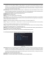
1
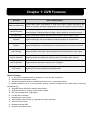
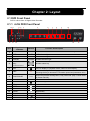
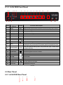
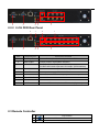
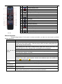
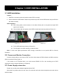
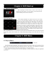
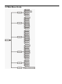
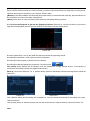
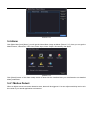
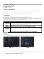
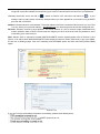
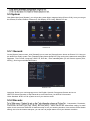
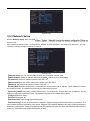
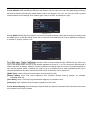
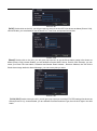
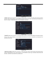
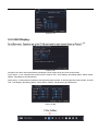
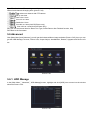
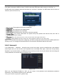
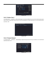
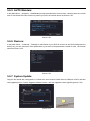
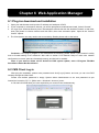
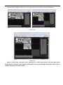
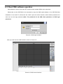
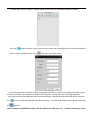
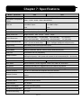
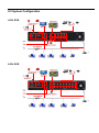
User Manual Contents SAFETY INSTRUCTION ........................................................................................................................................................... 1 CHAPTER 1: DVR FEATURES................................................................................................................................................ 1 CHAPTER 2: LAYOUT .............................................................................................................................................................. 2 2.1 DVR FRONT PANEL .............................................................................................................................................................. 2 2.1.1 4-CH DVR Front Panel ...................................................................................................................................... 2 2.1.2 8-CH DVR Front Panel ...................................................................................................................................... 3 2.2 REAR PANEL ......................................................................................................................................................................... 3 2.2.1 4-CH DVR Rear Panel ............................................................................................................................................. 3 2.2.2 8-CH DVR Rear Panel ...................................................................................................................................... 4 2.3 REMOTE CONTROLLER ......................................................................................................................................................... 4 CHAPTER 3 DVR INSTALLATION ......................................................................................................................................... 6 3.1 HDD INSTALLATION ............................................................................................................................................................. 6 3.2 CAMERA AND MONITOR CONNECTION ................................................................................................................................. 6 3.3 POWER SUPPLY CONNECTION ............................................................................................................................................... 6 CHAPTER 4: DVR START UP ................................................................................................................................................. 7 4.1 SYSTEM INITIALIZATION ....................................................................................................................................................... 7 4.2 LIVE SCREEN ........................................................................................................................................................................ 7 CHAPTER 5: DVR MENU ......................................................................................................................................................... 7 5.1 POP-UP MENU ....................................................................................................................................................................... 7 5.2 MAIN MENU GUIDE .............................................................................................................................................................. 8 5.3 MAIN MENU ......................................................................................................................................................................... 9 5.3.1 Record ........................................................................................................................................................................ 9 5.3.2 Main Menu ............................................................................................................................................................... 13 5.4 ALARM ............................................................................................................................................................................... 14 5.4.1 Motion Detect: ......................................................................................................................................................... 14 5.4.2 Video Blind: .............................................................................................................................................................. 15 5.4.3 Video Loss: .............................................................................................................................................................. 15 5.4.4 Alarm Input:.............................................................................................................................................................. 15 5.4.5 Alarm Output: .......................................................................................................................................................... 15 5.4.6 Abnormality: .......................................................................................................................................................... 16 5.4.7 Net Alarm: ................................................................................................................................................................ 16 5.4.8 Email: ..................................................................................................................................................................... 16 5.5 SYSTEM .............................................................................................................................................................................. 18 5.5.1 General:.................................................................................................................................................................... 18 5.5.2 Encode: .................................................................................................................................................................... 18 5.5.3 Network Setup ......................................................................................................................................................... 19 5.5.4 NetServer: ................................................................................................................................................................ 21 5.5.5 GUI Display:............................................................................................................................................................. 25 5.5.6 PTZ Config: .............................................................................................................................................................. 26 5.6 ADVANCED ......................................................................................................................................................................... 28 User Manual 5.6.1: HDD Manage .......................................................................................................................................................... 28 5.6.2: Account: .................................................................................................................................................................. 29 5.6.3: Online User: ............................................................................................................................................................ 30 5.6.4: Output Adjust: ......................................................................................................................................................... 30 5.6.5: AUTO Maitain: ........................................................................................................................................................ 31 5.6.6: Restore: ................................................................................................................................................................... 31 5.6.7: System Update:...................................................................................................................................................... 31 5.6.8: Device Info.: ............................................................................................................................................................ 32 5.7 INFO ................................................................................................................................................................................. 32 5.7.1 HDD INFO ....................................................................................................................................................................... 32 5.7.2 BPS ................................................................................................................................................................................. 33 5.7.3 LOG SEARCH ................................................................................................................................................................... 33 5.7.4 VERSION INFO ................................................................................................................................................................. 34 5.8 LOGOUT.............................................................................................................................................................................. 34 CHAPTER 6: WEB APPLICATION MANAGER .................................................................................................................. 35 6.1 PLUG-INS DOWNLOAD AND INSTALLATION .......................................................................................................................... 35 6.2 CMS CLIENT LOG-IN .......................................................................................................................................................... 35 6.3 CLIENT CMS SOFTWARE OPERATION .................................................................................................................................. 37 CHAPTER 7: SPECIFICATIONS ........................................................................................................................................... 40 CHAPTER 8: APPENDIX ........................................................................................................................................................ 41 8.1 PREVIEW............................................................................................................................................................................. 41 8.2 SUSTAINABLE RECORD TIME LIST ...................................................................................................................................... 41 8.3 MAIL BOX SERVER LIST ...................................................................................................................................................... 42 8.4 TROUBLESHOOTING ............................................................................................................................................................ 43 8.5 SYSTEM CONFIGURATION ................................................................................................................................................... 44 User Manual Safety Instruction 1. Read Instruction All the safety and operating instruction should be read before the equipment is operated. 2. Power sources This equipment should be operated only from the type of power source indicated on the marking label. If you are not sure of the type of power, please consult your equipment dealer. 3. Objects and Liquid Never push objects of any kind through openings of this equipment and / or spill liquid of any kind on the equipment as they may touch dangerous voltage points or short out parts that could result in a fire or electric shock. 4. Water and / or Moisture Do not use this equipment near water or in contact with water. 5. Heat sources Do not install near any heat sources such as radiators, heat registers, stoves or other apparatus (including amplifier) that produce heat. 6. Cleaning Unplug this equipment from the wall outlet before cleaning it. Do not use liquid aerosol cleaners. Use a damp soft cloth for cleaning. 7. Lightning Unplug this equipment during lightning storm or when unused for long periods of time. 8. Accessories Do not place this equipment on an unstable cart, stand or table. When a cart is used, use caution when moving the cart / apparatus combination to avoid injury from tip-over. 9. Moving Disconnect the power before moving the equipment. And the equipment should be moved with care. 10. Attachment Never add any attachments and/or equipment without the approval of the manufacturer as such additions may result in the risk of fire, electric shock and other personal injury. 11. Correct Batteries Risk of explosion occurs if battery is replaced by an incorrect type. Therefore you must use the same type of battery as the one being used in the product. 12.Ventilation. Do not block any ventilation openings, installation of the equipment in the rack should be such that the amount of airflow required for safe operation of the equipment is not compromised. 13.Overloading Do not overload wall outlets and extension cords to avoid the risk of fire or electric shock. 14.Reliable Earthlings (Grounding) Reliable grounding of rack mounted equipment should be maintained. Particular attention should be given to supply connections other than direct connections to the branch circuit. 1 Chapter 1: DVR Features Function Brief and Description Real-time Monitoring Double video output, with Monitor or VGA virtual output, support Net-viewer and Mobile Live monitor, and also support zoom in/out, auto sequence and PIP display. Record Function H.264 video compression format; record quality adjustable, multiple recording modes (Always, Scheduled, Manual, Alarm, Motion detection and remote record) Record storage Support SATA large capacity HDD and save real-time record image to HDD. Playback Support DVR single CH and multiple CH Search/Playback of recorded files. Backup Support DVR backup via USB flash drive, removable drive, Recorder and network. Alarm Setting Supports HDD & video input alarm management and external alarm signal inputs. Network operation Supports remote surveillance by authority users to increase system security. Mouse Operation Supports Mouse operation for faster menu navigation. PTZ Control Supports PTZ camera operations through RS-485. List 1-1 Other Features: H. 264 video compression format; supports D1, HD1 and CIF resolutions; ADPCM audio compression format; Windows Graphical interface; embedded real-time Linux 2.6 operation system; Multiple operations (Live, record, playback, backup, network surveillance and mobile phone monitoring simultaneously); Supports Double Encode bit network transmission; Supports remote live viewing via 3G mobile network; The video package time is adjustable; Friendly Menu reminder; Multiple alarm record mode Rear USB2.0 ports for back-up, upgrade and mouse operation; With IR remote control; Multiple language OSD; Supports auto maintenance Chapter 2: Layout 2.1 DVR Front Panel DVR is a short form of Digital Video Recorder. 2.1.1 4-CH DVR Front Panel 1511 123 4 5 6 7 8 9 12 13 14 16 Key title or Indicator Item 10 Remark 17 Function & Description 1 HDD HDD When the “Red” indicator flashes it means the hard drive is being read or written to. 2 NET NET NET indicator light 3 REC REC REC indicator light 4 ALARM 5 Number Key: ALARM ALARM indicator light select Number select key One\Two\Three\Four 6 ALL On Live display or Playback mode, switch to Quad display. 7 REC 8 PLAY/PAUSE 9 Enter into Main menu or Exit 10 MENU/ESC IR Receiver 11 UP Up button 12 LEFT Left button 13 14 15 16 17 DOWN RIGHT Enter USB Mouse USB Download Down button Right button Enter into Main menu Can be used on live screen Download recoding file List 2-1 ● Left direction key, Rewind key; Pressing the key to decrease PTZ rotation speed and parameter value. / Enter into [Record Search] Menu; Play record file. play / Pause frame by frame manually Receives IR signal from Remote Controller 2.1.2 8-CH DVR Front Panel 1814 123 4 5 6 7 8 9 10 11 12 13 15 16 17 Item Key title or Indicator 19 Remark 20 Function & Description 1 HDD HDD When the “Red” indicator flashes it means the hard drive is being read or written to. 2 NET NET NET indicator light 3 REC REC REC indicator light 4 ALARM 5 SEARCH 6 FULL 7 CH- Switch to previous channel 8 CH+ Switch to next channel 9 ALL On live mode, clicking the button will switch to Quad display. 10 REC 11 PLAY/PAUSE 12 MENU/ESC Enter into Main menu or Exit 13 IR Receiver Receives IR signal from Remote Controller 14 UP Up button 15 LEFT Left button 16 DOWN Down button 17 RIGHT Right button 18 Enter Enter into Main menu 19 USB Mouse USB Download Can be used on live screen 20 ALARM ALARM indicator light Record search ● Left direction key, Rewind key; Pressing the key to decrease PTZ rotation speed and parameter value. / Enter into [Record Search] Menu; Play record file. play / Pause frame by frame manually Download recoding file List 2-2 2.2 Rear Panel 2.2.1 4-CH DVR Rear Panel 4 7 2 1 8 9 6 5 3 2.2.2 8-CH DVR Rear Panel 4 8 7 9 Item 2 1 6 5 3 Physical port Connection method 1 Video input Connect CH1-8 (Virtual) video input device(BNC interface) 2 Video output Connect monitor output (BNC interface) 3 Audio I/O 4CH DVR: 4CH audio input and 1CH output; 8CH DVR: 8CH audio input and 1CH output. (RCA interface) 4 Ethernet: Port Connect LAN, Ethernet (RJ45 interface) 5 Power Port Connect power supply - DC12V 3A/5A 6 RS-485 RS485/Sensor/Alarm interface (see pin outs below) 7 Power Switch Power switch 8 Alarm Alarm Sensor 9 VGA Port Connect to VGA monitor, such as PC monitor (Optional) List 2-3 2.3 Remote Controller e Key title Search record file 1 2 Key function 1-8 Channel select 1-8; Numeric key 3 9-0 Numeric key 4 Multiple display mode 5 Exit key 6 ▲ 7 ◄/ 8 MENU 9 ▼ Up direction key Left/right direction key Enter into Main menu/Exit Down direction key 10 Pause/ Backward key 11 Slow play 12 Next frame key 13 Fast play key 14 Previous frame key 15 Play/ Pause key 16 Record key 17 ADD 18 FN 19 Add address key List2-4 Function key Many screen key List 2-4 Mouse Operation Except using buttons of front panel or remote controller, you also can use mouse to perform system operation. TYPE Function In menu lock mode, Enter into pop-up menu and clicking any sub menu to pop up Log-in window; on menu unlock mode, enter into pop-up menu, and then clicking left key to enter into any sub menu directly. Click left key of Mouse Click right key of Mouse Double-click Left key of Mouse Moving Mouse Sliding Mouse After entering into main menu, clicking left key could enter into any sub menu; On [Detailed file] menu mode, clicking left key could playback one recording file. Change the status of check box and motion detection area. Clicking combo box to access pull-down menu; Click left key to stop dwell time display when dwell time display is activated. By clicking left key you can adjust Color control bar and volume control bar. Clicking combo box to access pull-down menu By clicking left key you can select values in edit boxes or pull-down menu and supports Chinese word input, special symbol, numeric and character input, use instead of [Enter] or [Backspace ] In live display mode, clicking right key will display pop-up menu (shown as Picture 5-4a). In Main menu or sub menu mode, clicking right key will exit current menu. In live display or playback mode, double-clicking left key will maximize the screen. Select menu item On motion mode, sliding mouse will select motion area; On [Color set] menu mode, sliding mouse will adjust color control bar and volume control bar. List2-5 Chapter 3 DVR INSTALLATION 3.1 HDD Installation Caution: 1. Please do not Install or take out hard drive when DVR is running! 2. Some model has a HDD drawer. Please use provided key to take out the HDD drawer and put HDD into the drawer correctly. HDD Installation: After cutting power, remove screws on two sides of body and on rear panel and open DVR upper cover carefully; Connect data cable and power cord of HDD to main board securely shown as Picture 3-1. Picture 3-1 Fix the HDD back body shown as Picture 3-2; Put the upper cover back carefully, re-attach screws. Picture 3-2 Note: If users need higher performance HDD, strongly recommend to use special HDD for Security Protection. 3.2 Camera and Monitor Connection Connect camera cable to video input of DVR, and from video output of DVR to Monitor via BNC connector (Refer to section2.2-Rear Panel); or If the camera is a PTZ speed dome, you could connect RS485 A & B to the according port of DVR respectively (refer to system figuration on Chapter 8). 3.3 Power Supply connection Please only use the power adapter supplied with the DVR. After power on please make sure the video I/O connection well and select microphone and audio device with RCA cable. Chapter 4: DVR Start up 4.1 System Initialization After connecting the Power cable of DVR to wall outlet and pressing the Power button on the front panel, you will enter into the system initializing screen shown as Picture 4-1. Picture 4-1 4.2 Live screen After finishing initialization the system will enter into Live screen. Picture 4-2 is the 9-split display defaulted by system, which is showing no video input status. Once there are video inputs, the screen will display live images from the cameras. In Live mode, if you use the mouse to double-click the live image of any channel, the image will be maximized to full screen, by double-clicking again, image will be come back to 4-split or 9-split display mode; clicking the right button of the mouse will enter into Pop-up Menu; clicking the left button of the mouse allows you select menu items; and clicking any area outside the menu allows you exit the Pop-up menu. Picture 4-2 Note: When internal HDD is not connected or an error occurs ,the buzzer alarm comes .If you want to close the buzzer alarm, please enter into [Main menu AlarmAbnormality setting] to set No Disk, Disk Error, Disk no Space . Chapter 5: DVR Menu 5.1 Pop-up Menu Picture 5-1 After finishing system initialization, click right key of mouse on live mode to enter into Pop-up Menu On the bottom. Now you could perform parameter setting and operate on Main Menu, PTZ, borderline set, Playback, Soft Power Off. Single Channel, Quad, Nine Channel Window, 16 Channel Window. Note: options of the Pop-up menu will differ depending on different parameter setting and application environment. 5.2 Main Menu Guide 5.3 Main Menu Picture 5-2 After clicking right button of mouse, pop-up menu appears on the screen. You can click [main menu] option on pop-up menu mode to enter into Main menu interface (Shown as Picture 5-2). In Main Menu mode, you can control device management settings, such as Record, Alarm,System,Advanced,Inof and Logout. 5.3.1 Record Click [Main Menu] and [Record], you will get the Record Menu image as below (Picture 5-3), here you can get the Record Configer, Snapshot Storage setup, Playback and Backup. Picture 5-3 5.3.1.1 Press Record Conf. to enter into [Record Conf.] menu (Shown as Picture 5-4). Picture 5-4 [Channel] Choose the corresponding channel number to set the channel. Choose the all option to set the entire channels. All of the setting is based on single Channel, if you want to use the same setting to the other channels, you can simply click on the Advanced button on the bottom, Click Copy, and choose the channel you want to set to the same, back to the Advance Button again, and choose Paste, you will get the Channel same setup, Press OK to save the setting. [Redundancy] Choose the redundancy function option to implement the file double backup function. Double backup is writing the video files in two hard disks. When you do the double backup, make sure that there are two hard disks installed. One is read-write disk and the other is redundant disk. [Length] indicates maximum continuous record time 60 min. [PreRecord] set Pre Record time. [Mode] you can select different Mode of Recording: [Schedule] Once you select Schedule, you are allowed to set the recording time menus below, you can set the day in a week, the time period you want it recorder, you have 4 periods the most in a single day, for each period, Deferent Alarm Style is optional for you: Regular:Perform the regular recording in the set time section. The video file type is “R”. Detect: Trigger the “motion detect”, “camera mask” or “video loss” signal. When above alarm is set as opening recording, the “detection recording” state is on. The video file type is “M”. Alarm:Trigger the external alarm signal in the set time section. When above alarm is set as opening recording, the “detection recording” state is on. The video file type is “A”. [Manual] In the Manual Mode, the Recording wont start unless you start Recorder manually, press the Button on the front panel or select in the Alarm setting menu. [Alarm] Once Alarm is setup, Recording wont start only something Alarming Arouse. 5.3.1.2 Press the Snapshot Storage to get into the Snapshot menu (Picture 5-5) Picture 5-5 [Channel] Choose the corresponding channel number to set the channel. Choose the all option to set the entire channels. All of the setting is based on single Channel, if you want to use the same setting to the other channels, you can simply click on the Advanced button on the bottom, Click Copy, and choose the channel you want to set to the same, back to the Advance Button again, and choose Paste, you will get the Channel same setup, Press OK to save the setting. [PreSnap] set how many PreSnap Pictures you want. [Record] you can select deferent Mode of Recording under thes Snapshot Menu: [Schedule] Once you select Schedule, you are allowed to set the recording time menus below, you can set the day in a week, the time period you want it recorder, you have 4 periods the most in a single day, for each period, Deferent Alarm Style is optional for you: Regular, Detect, Alarm. [Manual] In the Manual Mode, the Recording wont start unless you start Recorder manually, press the Button on the front panel or select in the Alarm setting menu. [Alarm] Once Alarm is setup, Recording wont start only something Alarming Arouse. 5.3.1.3 Press the Playback to get into the Playback software (Picture 5-6), use the functions to get into the right Video and playback or back up from the DVR. Each Button Function list as below: Picture 5-6 5.3.1.3.1 (listed files): Look up the listed files that accord with the searching criteria. 5.3.1.3.2 (file information): Look up the found file information. 5.3.1.3.3 (file backup option): Choose the file to backup . 5.3.1.3.4 (file backup): Backup the chosen file. Click the button File backup (Note: Before the file backup, must be installed an enough storage device; If the backup is terminated, the already backup can playback individually.) Back up: Click on the Picture 5-7 in “4” with the button, enter in to the backup; Choose a storage device shown as Picture 5-8. Picture 5-7 Picture 5-8 Click “Backup” button and the dialog box is popped up. You can choose the backup file according to the type, channel and time. Click the play button to start the backup and click the pause button to stop the backup; shown as Picture 5-8 . Note: 1. Backup file will be saved as H264 format; you can playback the recorded files using the Multimedia Player program that comes with the DVR or through the net-viewer program. 2. Please make sure you have connected backup device, such as USB and DVD, well before backing-up. 5.3.1.3.5 (file searching): Search the file according to the searching parameter.(Picture 5-9) Picture 5-9 First click this button enter in to Search condition Select the playback file type. Select the playback channel,also can choose other channels to simultaneously play back. Search video files to set the starting time. Set the video file to search the end of time. skip Decode; Average Decode; Full Decode Synchronous playback requires all channels in the same time are existing video playback, also can say synchronous playback under the video files search out all channels that time frame are existing video files 5.3.1.3.6 (playback control): After the file is Selected, open the file, click play button to get the Video playback, in the Media choose play, Forwarder, or next file to do all of the control by deferent buttons on the bottom, also you can move the Blue Bar to move fast or Back to the point you want to check easily, and with this button Repeat your playback. Picture 5-10 , Note: Please select the file with *.h.264 format. The record file backed-up by U flash disk or removable disk is with *.h.264 format, and DVD Recorder with *.h.264 format. pic 5-11 The button functions from left to right in turn are as follows: [Play] button: start playing record file; [Pause] button: pause the record file playback. [Backward] button: backward the record file playback. [Stop] button: stop the record file playback. [Slow] button: slow play record file. [Fast Play] button: Fast playing the record file at X 1, X2, X3 and X4 speeds. [Previous frame] button: previous frame the record file playback. [Next frame] button: next frame the record file playback. [Previous file] button: Replay on a file. [Next file] button: Replay next file. [Circulation] button: Circulation playback. 5.3.1.3.7 (operation hint): Display the function of the cursor place. 5.3.2 Main Menu Main Menu—Record---Backup, get into the Backup menu (Picture 5-12), here is a special backup software, only for backup, please kindly note the deference from the Playback software, and also note: Before the file backup, must be installed an enough storage device; If the backup is terminated, the already backup can playback individually.) Use the Detect to find the Files you want to back up, press Backup to start, if you don’t want the files or it is wrong, Erase it or them, Stop gives the right to stop backup when you want a new start. Please kindly refer to the 5.3.2.3.4 for Normal operation on this. Picture 5-12 5.4 Alarm Click [Main Menu] and [Alarm], you will get the Alarm Menu image as below (Picture 5-13), here you can get the Motion Detect, Video blind, Video Loss, Alarm Input, Alarm Output, Abnormality, Net Alarm picture 5-13 Click [Alarm] button of the Alarm setup screen to enter into the interface.Now you are allowed to set detailed alarm parameters. 5.4.1 Motion Detect: When an object moves into motion detection area, alarm will be triggered. You can adjust sensitivity level to suit the needs of your actual application environment. picture 5-14 Detect] to enter into the [Motion Detection] menu shown as Picture 5-14. The [Motion detection] Menu has several sections, including Channel , Sensitivity and Motion area. Channel STATUS: This option allow you enable motion detection on any channel. Choose Enable to arouse the Motion Detection. SENSITIVITY: This option allows you to set sensitivity level of motion detection from highest to lowest with 6 being the most sensitive. Region: The channel is separated into a 22X18 area. When any object moves into the motion detection area, and the area where the object is located is displayed in red recording will be triggered. In the semi-transparent area the motion detection is off.(Picture 5-15) Picture 5-15 Note: As the setting are all based on single channel, if need set other channels same, With the tools in the Advanced Button, Copy the settings, and easier paste to other channels. 5.4.2 Video Blind: Users can accord need to camera Settings occluded area, make others not seeing occluded regional content. 5.4.3 Video Loss: When setting [Buzzer] to ON and when a camera has been disconnected. “Video Loss” icon will also appear on the screen with buzzer sound. Set to OFF, you will only see the “Video Loss” appear but no sound. 5.4.4 Alarm Input: setting of exterior alarm. 5.4.5 Alarm Output: setting of output. 5.4.6 Abnormality: Abnormality parameter setup. 5.4.7 Net Alarm: settings for net alarm parameters. Buzzer time: you can set how long the buzzer will sound when motion is detected (0s, 10s, 20, 40s, 60s); Alarm duration time: you can set how long alarm record will last when alarm ends (0s, 30s, 1minute,2minute, 5minute); Pre-record time: you can set how long record will last before alarm occurs (Off, on). 5.4.8 Email: The option allows you set the alarm images is issued to a specified email or not. You could freely select buzzer alarm or not and alarm output time for all the alarm types, and for the MD alarm and I/O status alarm you could set email and full screen reminder. Alarm Type Video Loss Function Sends alarm when DVR can’t receive video signal (such as camera damage, cable broken or damaged or power supply malfunction). Motion Detection When an object moves into motion detection area, alarm will be triggered. You can adjust sensitivity level to suit the needs of your actual application environment. I/O Status System can convert alarm signal triggered by external sensor into signal identified by system. HDD loss When Hard Drive is not detected (HDD damage, power supply malfunction), or HDD auto-overwrite is off, and free space is not enough, an alarm will be triggered. EMAIL Setup Click[Main Menu→System→NetService]to enter into the interface shown as Picture 5-16 Picture 5-16 Picture 5-17 On the [EMAIL] screen, when Enabling [Email] option, you can set its parameters shown as Picture 5-17 SMTP server: indicates server address you use. Port: indicates sender port of SMTP server. Generally the SMTP port value is 25, but there are exceptions, for example, SMTP port of G-mail server should be 465. Need SSL: is a security link transport protocol. You can encrypt your communication info (including your email) using SSL to prevent hackers from monitoring your email or communication info and even your password. Generally Gmail.com server set SSL to [ ] shown as Picture 5-25, and other mail server to [ ]. If your setting is still not right, please contact the web site where you have applied for your email box to get SMTP port and SSL of mail box. Sender: indicates sender’s email address. The email address should be consistent with the server you use. That is to say, when you use email address – [email protected], the according server should be smtp.gmail.com. Receiver: indicates receiver’s email address. The email address is used to receive image transmitted from motion detection alarm of DVR. Please clear the images you have received as soon as possible to avoid overloading your email account. Note: Sender email is required to enable IMAP/POP3/SMTP function (details please refer to Picture 5-18 & Picture 5-19, which show IMAP/POP3/SMTP Enable setting function for Gmail, SINA mail). Login your GMAIL ID and turn to Settings page. Find out Forwarding and POP/IMAP option and then tick-select [enable IMAP] option. Picture 5-18 Picture 5-19 If you can’t receive email alarm information successfully, please check below points: t SMTP protocols or not; 5.5 System Click [Main Menu] and [System], you will get the system Menu image as below (Picture 5-20), here you can get the General, Encode, Network, Netservice, GUI Display, PTZ Config, RS232,Tour etc. Picture 5-20 5.5.1 General: On the [System] menu screen, click [General] icon to enter into [General] menu shown as Picture 5-21. Now you are allowed to modify system Time, [date/time],Data format [setup DST (day saving time) status and mode] Data Separator, Time Format, Language, HDD Full, DVR No., Video standard[allow you set Camera system (PAL, NTSC).], Auto Logout and Machine Name. Picture 5-21 Language: Select your own language menu, like English, Spanish, Portuguese,Germen and so on HDD Full: Select Overwrite or Stop Recorder to avoid loss when your HDD is full recorded. Video Standard: NTSC or PAL system set to fit your devices need. 5.5.2 Encode: -22 , Compression, Resolution, Frame Rate, Bit Rate Type (Fps), Quality, Bit Rate (Kb/s), I frame Interval and Video/Audio setting, for each option, there are several selection for deferent setup to suit your working situation. Here we have Extra Stream setting, this is for the Internet transport, you can set it to proper statue to suit your Network condition. Picture 5-22 5.5.3 Network Setup 5.5.3.1: Network setup: Enter into [Mai picture 5-23): After selecting network mode - such as DHCP, PPPOE or static allocation- and setting up web ports,you can visit DVR remotely through a network or internet. Picture 5-23 【Network card】You can choose cable network card or wireless network card. 【DHCP Enable】Obtain IP address automatically.Note:DHCP server is preinstalled. 【IP address】Set the IP address. Default: 192.168.1.10. 【Subnet mask】Set the subnet mask code. Default: 255.255.255.0. 【Gateway】Set the default gateway. Default: 192.168.1.1. 【Primary DNS】Domain Name Server. It translates the domain name into IP address. The IP address is offered by network provider. The address must be set and reboot then it works. 【Secondary DNS】Secondary Domain Name Server. It translates the domain name into IP address. The IP address is offered by network provider. The address must be set and reboot then it works. 【TCP port】Default: 34567. 【HTTP port】Default: 80. 【HS Download】Internet High-Speed Download; 【Transfer Policy】There are three policies: Adaption, image quality precedence and fluency precedence. The code stream will adjust according to the setup. Adaption is the tradeoff between the image quality precedence and fluency precedence. Fluency precedence and self-adaption are valid only when the assistant code stream is turned on. Otherwise image quality precedence is valid. DNS: DNS server is generally provided by local ISP. Herein please enter the IP address of your DNS. 5.5.3.2: PPPOE: When selecting PPPoE form the Enable, user can input user name and password provided by ISP and set Media and Web port (details please refer to the Picture 5-24). You can visit your DVR via public network without port forwarding when network type is set to “PPPoE” and web port is right. Picture 5-24 5.5.3.3: DDNS: DDNS (Dynamic DNS) is a service that register a domain name and the floating IP address with the DDNS server so that the domain name can be routed to the IP address even if the IP address is changed in a dynamic IP system.( Picture 5-25) Picture 5-25 to setup the DVR to be accessed through a DDNS service. When you click on the DDNS button it brings up the window displayed as Picture 5-7. You can access the DVR through a static or dynamic IP address; however a dynamic address can change from time to time. How often depends on your service provider When it changes you need to go to a website such as www.myipaddress.com from a computer attached to the same router as the DVR to find out what the new IP address is. [DDNS Type]: select a Dynamic domain name server provided by ISP; [Domain Name]: Input host name registered from Dynamic Domain Naming System, for example: DVR2009.3322.org; [User Name]: Input a user name registered before applying for a domain name; [Password]: Input a password you set when registering a user name. 5.5.3.4: Router Mapping: Port forwarding is required when you want to access the DVR connected to the router from outside of the router’s network. Picture 5-26 1. Input router’s IP address from IE-based browser to open the Router configuration interface; 2. Click [Advanced] option to take you to the port forwarding instructions for your router; 3. Set the corresponding parameters illustrated in Picture 5-26. When server port and web port forwarding the DVR IP address, user can visit the DVR remotely. 4. User can enter below website or domain name as per current PC network environment to visit the remote DVR. 1. http://public IP: Web port(such as 80) 2. http://intranet IP: Web port(such as 34567)(only available at the same LAN) 3.http://superdvr.3322.org: Web port(such as 80) Friendly Reminder: The router’s port forwarding interface may be different, however, when entering into virtual server, user will always need forward port 80 and port 34567 of router to IP address of DVR allocated or automatically captured, and select [All] or [Both] in corresponding protocol column and save the above setting. Above steps may differ from the router device depending on the manufacturer. 5.5.4 NetServer: Go to [Main menu - 27: Picture 5-27 【PPPOE】Double click on the info, you will get a pop-up menu to set the PPPOE infos shows as below (Picture 5-28), choose Enable, you are allowed to set the User Name, Password and IP Address. Picture 5-28. 【NTP】Double click on the info, you will get a pop-up menu to set the NTP infos shows as below (Picture 5-29), choose Enable, you are allowed to set the Server IP, Time Zone and Update Period infos. Picture 5-29 【Email】Double click on the info, you will get a pop-up menu to set the Email Alarm setting infos shows as below (Picture 5-30), choose Enable, you are allowed to set the SMTP Server, Port No, SSL selection, you can name your Email The User Name, Password and Sender Email Address , Receiver Address, the Title Of the Email Alarm image default is Alarm Message, you can set any title you want. Picture 5-30 【IP FILTER】Double click on the info, you will get a pop-up menu to set the IP FILTER setting infos shows as below (Picture 5-31), choose Enable, you are allowed to set the Restricted Type, then fit the IP right in the Add blank. Picture 5-31 【FTP】Double click on the info, you will get a pop-up menu to set the FTP setting infos shows as below (Picture 5-32), choose Enable, you are allowed to set the Server IP, the Port, User Name and Password, the Max File Length is 128M (Selectable), Fill your DirName in the blank. Picture 5-32 【ARSP】Double click on the info, you will get a pop-up menu to set the ARSP setting infos shows as below (Picture 5-33), choose Enable, you are allowed to set the Server IP, the Port, User Name and Password, The Update Period setting. Picture 5-33 【Wireless Config】Double click on the info, you will get a pop-up menu to the Wireless Config setting image shows as below (Picture 5-34), choose Enable, you are allowed to set the Type, Wireless Access Point, Dial Number, User Nmae and Password, Ip Address etc.. Picture 5-34 【Mobile Monitor】Double click on the info, you will get a pop-up menu to the Mobile Monitor setting image shows as below (Picture 5-35), choose Enable, you are allowed to set the Mobile Monitor Port.. Picture 5-35 Note: For more information about how to use a Mobile to view the DVR and other devices via the DVR, please kindly refer to the Mobiel Viewer Instruction along with this User MANUAL. 【UPNP】Double click on the info, you will get a pop-up menu to the UPNO setting image shows as below (Picture 5-36), choose Enable, you are allowed to set the HTTP Port, TCP Port, Mobile Port, make sure UPNP is running on router before using this. Picture 5-36 【WIFI】Double click on the info, you will get a pop-up menu to the WIFI setting image shows as below (Picture 5-37), choose Enable, you are allowed to set the SSID,Password, Ip Address, Subnet Mask and Gateway here.. Picture 5-37 5.5.5 GUI Display: - 38 Picture 5-38 Configure the video output parameters including the front output mode and code output mode. Front output:In the local preview mode include: channel Title, Time Display, Recording Status, Alarm Status, Deflick, Transparency and Resolution. Code output:In the network surveillance and video file mode include: In the local preview mode include: channel Title, Time Display, Recording Status, Alarm Status, Deflick, Transparency and Resolution. Picture 5-39a Picture 5-39b Set the selective image parameters (current channel for single window display and cursor place for multi-window display). You can use the desktop shortcut menu and enter the interface. The image parameters include: Period, brightness, contrast, saturation, Hue and Gain. You can set different parameters at different time sections.(shown as picture 5-39a or 5-39b) 5.5.6 PTZ Config: Enter into [Main menu PTZ Config] to select the channel you desire to control and set PTZ protocol (Pelco-D or Pelco-P), Baud Rate (1200, 2400, 4800, 9600), Data bit (8, 7, 6, 5), Stop bit (1, 2), Parity Check (None, Odd, Even, Mark, Space), Address Code and Cruise status respectively. Please note the PTZ device can be activated only when a channel in connection with the PTZ camera is selected.( Picture 5-40) Picture 5-40 Picture 5-40a Picture 5-40b picture 5-40c Open auto cruise function on PTZ setting menu if you want to setup cruise function (system default: on), and set up cruise channel, cur point and total quantity and stop time etc. Channel select: select one channel with PTZ camera Pattern: set up pre-set bit quantity indicates starting point cruised scan a path. System default point is 01. : sets the pan path. Tour:allow you go to a specific preset point. Preset:allow you set a set of specific preset points of a PTZ camera. 1. Select a camera you desire to set a preset point; 2. Adjust the camera in a desired direction 3. Click [Set] to set the point as preset point 4. Click [Save] to save the preset point 5. Follow the above step to add one more preset point. Bolder: Config the point PTZ go to. Del Preset: allow you delete one selected preset. Note: Up to 255 preset bits for the DVR can be stored. However, actual preset quantity differs depending on PTZ performance. 5.5.7 RS232: Enter into [Main menu RS232] to select the RS232 Information, ( Picture 5-41) Functions (None, Transparent, Gerneral, Longyang, Keyboard….) ( Picture 5-42), Baud Rate (1200, 2400, 4800, 9600….115200), Data bit (8, 7, 6, 5), Stop bit (1, 2), Parity Check (None, Odd, Even, Mark, Space), .( Picture 5-43). This information should be compatible with the PTZ camera. Picture5-41 Picture5-42 Picture5-43 5.5.7 TOUR picture 5-44 Open Tour function on Tour setting menu if you want to setup tour function (system default: off), and set up tour channel and channels changing time. (picture 5-44) : select one channel with PTZ camera : set up tour time View 1ch at 1 time :View 1ch at 1 time View 8ch at 1 time :View 9ch at 1 time(16ch DVR have only) :View 16ch at 1 time(16ch DVR have only) Also you can set Interval time for Alarm Tour Type, Select Return after Finished function, help DVR back to the first statue. 5.6 Advanced Click [Main Menu] and [Advance], you will get the Advanced Menu image as below (Picture 5-45), here you can get the HDD Manage, Account, Online User, Output Adjust, AutoMaintain, Restore, Upgrade and Device Info etc. Picture 5-45 5.6.1: HDD Manage In the [Main Menu Advanced shown as Picture 5-46. HDD Manage] screen, highlight and click [HDD] icon to enter into the window Picture 5-46 When DVR is connected to a HDD, the system will automatically detect if HDD is normal or not; If the cable connected to HDD is loosen or HDD is abnormal, HDD status will be shown as “No Disk”, or, If HDD need to be formatted, status will be shown as “no format”, otherwise, the HDD status will be shown as “Normal” (refer to Picture 5-47). Picture 5-47 :The equipment can write or read data. :The equipment can snapshot data. The equipment can read data. Double backup the video files in the write-read disk. If you select “format disk” the system will tip this operation will clear the disk, click “OK” to continue, or “Cancel” to abort. When disk status hint error, click recover button will regain disk errors. Click partition disk was divided into many partitions carries on the video store. Note: It is an important first step when configuring your DVR to make sure that the hard drive (HDD) options are correctly set. So, it is strongly recommended that you do format the HDD before start the first record. 5.6.2: Account: In the [Main Menu Advanced Account] screen, there have admin, guest and default users, with deferent author rights, also you can do some more operation here, like Modify User rights, make User Group, Modify Password, if you are the Admin, you ADD some more users if you need, and only the Admin User can change all of the parameters, the window shown as Picture 5-48. Picture 5-48 When you set Password Enabled to “ON”, you can setup a user password and administrator password respectively. The password supports up to 6 characters. The system default no password. (picture 5-49) picture 5-49 5.6.3: Online User: In the [Main Menu Advanced Online User] image, if you are the Admin user, you can see all of the user name who got online using with the DVR, and you can do the operation to make disconnect or not. the window shown as Picture 5-50. Picture 5-50 5.6.4: Output Adjust: In the [Main Menu Advanced shown as Picture 5-51. Output Adjust] to adjust the output size to suit your monitor or lcd. the window Picture 5-51 5.6.5: AUTO Maintain: In the [Main Menu Advanced AutoMaintain] to make Auto Maintain, here set Auto –reboot system at a certain time or Auto-delete Old Files function to protect your DVR, the window shown as Picture 5-52. Picture 5-52 5.6.6: Restore: In the [Main Menu Advanced Restore] to make Reset of your DVR to recover all the DVR settings back to factory set, you can choose all of the parameters or just some of the parameters needed to reset , the window shown as Picture 5-53. Picture 5-53 5.6.7: System Update: Copy the file named with “dvrupgrade” to U flash drive; and connects U flash drive to USB port of DVR, and then click [upgrade] menu. Find the Upgrade software Position, and click upgrade to start upgrade.(picture 5-54) picture 5-54 Note: 1. Please obtain the updated program from supplier before system updating. 2. Please not cut power and unplug U flash during the update. 3. System will automatically restart after system update. 4. User needs to manually recover the default setting after restarting. local disk finishing ex-factory 5.6.8: Device Info.: Check your DVR device info in the [Main Menu -55) Picture 5-55 5.7 Info Click [Main Menu] and [Info], you will get the Info Menu image as below (Picture 5-56), here you can get the HDD Info, BPS, LOG and Version etc. Picture 5-56 Picture5-57 5.7.1 HDD Info Enter into [Main MenuInfoHDD Info] to check your HDD infos for each channel, picture 5-57, 5.7.2 BPS Enter into [Main MenuInfoBPS] to check your Bit rate infos for each channel, picture 5-58 Picture5-58 5.7.3 Log Search Enter into [Main MenuInfoLOG] shown as Picture 5-59 Picture 5-59 Select log type, enter start date & end date, and then click the [Search] button on the bottom of the interface to search all the logs you need shown as Picture 5-60. Picture 5-60 5.7.4 Version Info Enter into [Main MenuInfoVersion Info] to check the Record channels, System Version, shown as Picture 5-61 Picture 5-61 5.8 Logout Click [Main Menu] and [Logout], you will get the Info Menu image as below (Picture 5-62), here you can get the Logout to extra the menu, Shutdown the Device, or you can reboot the DVR here if you want. Picture 5-62 Chapter 6: Web Application Manager 6.1 Plug-ins download and installation 1. Open your web browser and input the IP address and web port of DVR; 2. If your computer is connected to internet, you will be prompted to download and install “ActiveX Control”; 3. You may have “Windows Security Alert” that attempts to block this with the windows Firewall. In that case, click [Tool] button to choose Internet and click Safe ,then enter automatic option. Open all the “ActiveX Control” options . 4. The Vista system user may need to set user authority. Details please refer to the below: Reminder: If the plug-in program is not downloaded successfully, please check if your browser’s safety level or firewall setting is too advanced. Also refer to section 5.5.3 Network Setup to make sure network configuration is correct, ports are forwarded correctly, and ActiveX is enabled. Note: If you want to delete old IE ActiveX at DVR system update, enter C:\Program Files\Net Surveillance delete Net Surveillance. 6.2 CMS Client Log-in After plug-ins installation, please enter password and click [Log-in] button, and now you can view DVR remotely through the Web Client. Please note default password is empty. System allows Administrator to set new password as per instructions in section 5.5.7.2 - [Main menu –Advanced –Account ] menu. 4-CH and 8-CH DVR allow you have respectively ten users on-line simultaneously. Picture 6-1 After successful logging-in web client, you will enter into the live interface shown as Picture 6-2. 4CH 8CH Picture 6-2 Picture 6-3 Note: If client needs to monitor voice, should be in a voice input picture, click the right mouse button audio (in listening, must want to sound before the encode Settings will channel audio must be enabled, otherwise no sound output). 6.3 Client CMS software operation CMS software is used on the same PC, support control multiple DVRs at the same time. Please take out the CD-ROM in the accessories, copy the CMS install software in the CD-ROM After installation on the local PC, double click the “CMS”, open the control interface, default without password, the client can set the login password (Note: The password for the CMS client password, no DVR login password). Picture 6-4 CMS login interface After you enter into the CMS interface, shown in Picture 6.5: Picture 6.5 CMS control interface Click the right corner of “System” settings, switch to the control of management options as below: First click to add a domain, region name are free to take, after determining the list of selected regional areas to create a domain name, select add device as shown below: As the follow prompts to input the DVR device requires information, confirmed and adding successful, repeat the above operation, can be added to multiple DVR equipment, management and monitoring operations. If you want to modify the equipment which have added before, selected the modify the DVR at first, then click the for icon to modify the parameters, but also can delete the DVR which added on the regional list already deletion. After completed add DVR these steps, click the label of the right corner for real-time monitoring, switch to multi-monitor screen interface, double-click the top left column of the DVR channel device can carry out real-time monitoring. This manual describes only the basic operations, the detailed operation please refer to the electronic manual CD-ROM; Equipment updated in real time, if upgraded without notice; If have doubt or dispute for product description, all as to the ultimate interpretation of the company; The manual for the number of products that do reference the specific operation of each product is not an Chapter 7: Specifications Model parameter 4CH Video System 8CH NTSC/PAL(Optional) Video/Audio Compression Format Video:H.264 Audio:8kHz*16bit ADPCM Video I/O 4-CH BNC input 1-CH BNC output; VGA 8-CH BNC input 1-CH BNC output; VGA Audio I/O 4-CH input / 1-CH output 8-CH input / 1-CH output Display Resolution D1:704×576(PAL) 704×480 (NTSC) Display frame rate Single Channel PAL:25 fps ,NTSC:30 fps Record Resolution PAL: QCIF(352*288) CIF(352*288) HD1(704*288) NTSC: QCIF(352*288) CIF(352*240) HD1(704*240) Record Total frame rate D1 (704*576) D1 (704*480) PAL:(D1,HD1,CIF,QCIF)100fps PAL:50fps@D1,50fps@HD1,200fps(CIF,QCIF) NTSC:(D1,HD1,CIF,QCIF)120fps NTSC:60fps@D1,60fps@HD1,240fps(CIF,QCIF) Image Quality Best /Better/ Good /General/ Worse/ Worst HDD Support USB removable HDD and SATA HDD Record Mode Always, Scheduled, Manual, motion, Alarm, Web Client record. Pack Time 15/30/45/60/120 min (adjustable) Backup Function Support U flash disk, removable HDD, recorder and network backup; Backup file format is *.264 format and network file will automatically be *.264 format). Playback Mode Normal play, Fast Forward, Rewind and slow play frame by frame. Alarm I/O 4-CH input / 1-CH output Alarm Mode Motion Detection, Sensor triggered, Video Loss, HDD Full, HDD Error PTZ control Embedded RS-485 port / supports PELCO-P & PELCO-D protocol. USB Port Support Mouse, removable HDD and U flash disk backup and upgrade. Network Interface One RJ-45 10M/100M self-adaptable Ethernet interface. Network Function Support Mobile surveillance, IE browsing, Remote Live surveillance and parameter setting. Network Protocol Supports TCP/IP, DHCP, UDP, DDNS, PPPOE network Protocol IR remote control Support IR remote control. Power Adapter DC 12V&3A Power Consumption 10~15W (excluding HDD) Operational Temperature 10℃~+40℃ Operational Humidity 10%~90% List 7-1 4-CH input / 1-CH output Chapter 8: Appendix 8.1 Preview You can right click mouse to choose the switch between the windows. The system date, time and channel name are shown in each viewing window. The surveillance video and the alarm status are shown in each window. 1 Recording status 3 Video loss 2 Motion detect 4 Camera lock List 8-1 8.2 Sustainable Record Time List The sustainable record time differ depending from Resolution, Para, Video Input, Image parameter and Audio input etc. Factor: Audio set to ON / 4-CH video input / Twenty-four hours Continuous record / 250G HDD / Unit: Day Quality (Image Quality) Resolution Best Good Middle D1 2048 1024 768 CIF 1024 512 384 List 8-2 Calculation formula: 250 1024 1402 24 When using 250G HDD and Record for 4-CH occupies 1402M space per hour, system can continuously record 183 hours. 8.3 Mail box server List Web site Mail box Sender server(25) Receiver server(110) @163.com smtp.163.com pop3.163.com @vip.163.com smtp.vip.163.com pop.vip.163.com @188.com smtp.188.com pop.188.com @126.com smtp.126.com pop3.126.com @netease.com smtp.netease.com pop.netease.com @yeah.net smtp.yeah.net pop.netease.com @qq.com smtp.qq.com pop.qq.com smtp.163vip.net popx.163vip.net @sina.com.cn smtp.sina.com.cn pop3.sina.com.cn @yahoo.com.cn smtp.mail.yahoo.com.cn pop.mail.yahoo.com.cn @yahoo.com smtp.mail.yahoo.com pop.mail.yahoo.com google.com @gmail.com smtp.gmail.com(465/587) pop.gmail.com(995) www.china.com @china.com smtp.china.com pop.china.com www.sohu.com @sohu.com smtp.sohu.com pop.sohu.com smtp.163.net pop.163.net smtp.163vip.net pop.163vip.net www.163.com www.qq.com 163.net www.sina.com www.yahoo.com Mail.163.com Mail.163vip.com Mail.tom.com @tom.com smtp.tom.com pop.tom.com Mail.263.com @263.net smtp.263.net pop3.263.net smtp.x263.net pop.x263.net smtp.263.net.cn pop.263.net.cn smtp.139.com pop.139.com smtp.21cn.com pop.21cn.com vip.21cn.com vip.21cn.com etang.com smtp.etang.com pop.etang.com elong.com smtp.elong.com pop3.elong.com x263.net 263.net.cn 139 mail box 21cn.com Vip.21cn.com @139.com List 8-3 8.4 Troubleshooting 1. 2. 3. 4. 5. 6. 7. 8. 9. 10. 11. Q: What can I do if the system does not detect the HDD? A: Check if the power supply system is properly connected and data cord and power cables are securely connected. Q: We have changed the password but do not remember the new password, how can we access the system? A: If you forget system password, please consult with the service personnel. Q: We are not getting any video signal on the DVR, what is wrong? A: Check camera video cable and connections; or check monitor video cable and connections; or confirm that the camera has the power and / or check camera lens setting. Q: Why some channels display just a blank screen even if they receive video sources? A: Check if the camera is connected to the system properly displays the image; check if the camera is properly supplied with power. Q: Can the DVR have problems if it gets too hot, how can I prevent this? A: The DVR has a fan to help it dissipate heat while it is running. Please place the DVR in a place where there is good air circulation and away from heat sources to increase stability and life of the DVR. Q: “Record” Can not work normally, how to deal with? A: Check if the current screen is in Play mode, pressing [Stop] button to exit the Play mode and then you can enter into the [Record] function. Q: Why the Remote Controller can’t work normally? A: Check if the battery is power off; or check if the Remote Controller is broken. Q: Can we records whilst playing-back? A: Yeah, you can do it. The system support you records whilst playing-back. Q: Can we erase some recorded file from DVR. A: Considering the safety factor, you can’t delete the recorded file directly from the device. When you actually erase all the recorded files, please select HDD format function Q: Why does the Buzzer keep sounding? A: Please check if motion detection is on and the system has detected motion, make sure the HDD is being detected and has sufficient space available; check if video has lost etc. Q: Why can’t stop [Stop] function? A: Pressing [Stop] button only can stop manual record. If you want to stop Scheduled record, please revise to [No Record] during this period. 8.5 System Configuration 4-CH DVR 8-CH DVR