Download Slide Compound Miter Saw

Transcript
ENGLISH (Original instructions)
INSTRUCTION MANUAL
Slide Compound Miter Saw
LS1018
LS1018L
015203
DOUBLE INSULATION
IMPORTANT: Read Before Using.
1
ENGLISH (Original instructions)
Contents
SPECIFICATIONS ....................................................................................................................................................... 2
General Power Tool Safety Warnings .......................................................................................................................... 3
MITER SAW SAFETY WARNINGS ............................................................................................................................. 4
INSTALLATION............................................................................................................................................................ 6
FUNCTIONAL DESCRIPTION..................................................................................................................................... 6
ASSEMBLY ............................................................................................................................................................... 11
OPERATION.............................................................................................................................................................. 14
MAINTENANCE ........................................................................................................................................................ 19
OPTIONAL ACCESSORIES ...................................................................................................................................... 21
SPECIFICATIONS
Model
LS1018 / LS1018L
Blade diameter
255 mm - 260 mm
Blade body thickness
1.6 mm - 2.4 mm
Hole diameter
For all countries other than European countries
25.4 mm
For European countries
30 mm
Max. Cutting capacities (H x W) with 260 mm in diameter
Bevel angle
Miter angle
45° (left)
0°
45° (right)
0°
50 mm x 310 mm
91 mm x 310 mm
31 mm x 310 mm
45°
50 mm x 220 mm
91 mm x 220 mm
31 mm x 220 mm
60° (right)
-
91 mm x 153 mm
-
No load speed (min-1)
4,300
Laser Type (LS1018L only)
Red Laser 650 nm,
Dimensions (L x W x H)
1mW ( Laser Class 2 )
825 mm x 536 mm x 633 mm
Net weight
For all countries other than European countries………19.8 kg
For European countries…………………………………….…19.9 kg
Safety class
/II
• Due to our continuing program of research and development, the specifications herein are subject to change without notice.
• Specifications may differ from country to country.
• Weight according to EPTA-Procedure 01/2003
END222-4
・
The following show the symbols used for the equipment.
Be sure that you understand their meaning before use.
・ Read instruction manual.
・
Symbols
・
DOUBLE INSULATION
・
To avoid injury from flying debris, keep
holding the saw head down, after
making cuts, until the blade has come to
a complete stop.
・
When performing slide cut, first pull
carriage fully and press down handle, then
push carriage toward the guide fence.
・
・
・
2
Do not place hand or fingers close to the
blade.
Adjust sliding fences clear of blade and
blade guard properly.
Always remove SUB-FENCE R when
performing right bevel cuts. Failure to do so
may cause serious injury to operator.
LASER RADIATION: Do not stare into beam.
Direct laser beam may injure your eyes.
Only for EU countries
Do not dispose of electric equipment
together with household waste material!
In observance of the European Directive, on
Waste Electric and Electronic Equipment
and its implementation in accordance with
national law, electric equipment that have
reached the end of their life must be
collected separately and returned to an
environmentally compatible recycling facility.
Conforms to the following European Directives:
2006/42/EC
They are manufactured in accordance with the following
standard or standardized documents:
EN61029
The technical file in accordance with 2006/42/EC is
available from:
Makita, Jan-Baptist Vinkstraat 2, 3070, Belgium
ENE006-1
Intended use
The tool is intended for accurate straight and miter
cutting in wood. With appropriate saw blades, aluminum
can also be sawed.
ENF002-2
Power supply
The tool should be connected only to a power supply of
the same voltage as indicated on the nameplate, and can
only be operated on single-phase AC supply. They are
double-insulated and can, therefore, also be used from
sockets without earth wire.
30.5.2014
ENG905-1
000331
Noise
The typical A-weighted noise level determined according
to EN61029:
Yasushi Fukaya
Director
Makita, Jan-Baptist Vinkstraat 2, 3070, Belgium
Sound pressure level (LpA) : 97 dB (A)
Sound power level (LWA) : 103 dB (A)
Uncertainty (K) : 3 dB (A)
GEA005-3
General Power Tool Safety
Warnings
Wear ear protection
WARNING Read all safety warnings and all
instructions. Failure to follow the warnings and instructions
may result in electric shock, fire and/or serious injury.
ENG900-1
Vibration
The vibration total value (tri-axial vector sum) determined
according to EN61029:
Save all warnings and
instructions for future reference.
Vibration emission (ah) : 2.5 m/s2 or less
Uncertainty (K) : 1.5 m/s2
The term "power tool" in the warnings refers to your
mains-operated (corded) power tool or battery-operated
(cordless) power tool.
Work area safety
1.
Keep work area clean and well lit. Cluttered or
dark areas invite accidents.
2.
Do not operate power tools in explosive
atmospheres, such as in the presence of
flammable liquids, gases or dust. Power tools
create sparks which may ignite the dust or fumes.
3.
Keep children and bystanders away while
operating a power tool. Distractions can cause
you to lose control.
Electrical safety
4.
Power tool plugs must match the outlet. Never
modify the plug in any way. Do not use any
adapter plugs with earthed (grounded) power
tools. Unmodified plugs and matching outlets will
reduce risk of electric shock.
5.
Avoid body contact with earthed or grounded
surfaces such as pipes, radiators, ranges and
refrigerators. There is an increased risk of
electric shock if your body is earthed or grounded.
6.
Do not expose power tools to rain or wet
conditions. Water entering a power tool will
increase the risk of electric shock.
ENG901-1
•
•
•
•
The declared vibration emission value has been
measured in accordance with the standard test method
and may be used for comparing one tool with another.
The declared vibration emission value may also be
used in a preliminary assessment of exposure.
WARNING:
The vibration emission during actual use of the power
tool can differ from the declared emission value
depending on the ways in which the tool is used.
Be sure to identify safety measures to protect the
operator that are based on an estimation of
exposure in the actual conditions of use (taking
account of all parts of the operating cycle such as
the times when the tool is switched off and when it
is running idle in addition to the trigger time).
ENH003-15
For European countries only
EC Declaration of Conformity
Makita declares that the following Machine(s):
Designation of Machine:
Slide Compound Miter Saw
Model No./ Type: LS1018, LS1018L
3
19.
Do not use the power tool if the switch does
not turn it on and off. Any power tool that cannot
be controlled with the switch is dangerous and
must be repaired.
20. Disconnect the plug from the power source
and/or the battery pack from the power tool
before making any adjustments, changing
accessories, or storing power tools. Such
preventive safety measures reduce the risk of
starting the power tool accidentally.
21. Store idle power tools out of the reach of
children and do not allow persons unfamiliar
with the power tool or these instructions to
operate the power tool. Power tools are
dangerous in the hands of untrained users.
22. Maintain power tools. Check for misalignment
or binding of moving parts, breakage of parts
and any other condition that may affect the
power tool’s operation. If damaged, have the
power tool repaired before use. Many accidents
are caused by poorly maintained power tools.
23. Keep cutting tools sharp and clean. Properly
maintained cutting tools with sharp cutting edges
are less likely to bind and are easier to control.
24. Use the power tool, accessories and tool bits
etc. in accordance with these instructions,
taking into account the working conditions
and the work to be performed. Use of the power
tool for operations different from those intended
could result in a hazardous situation.
Service
25. Have your power tool serviced by a qualified
repair person using only identical replacement
parts. This will ensure that the safety of the power
tool is maintained.
26. Follow instruction for lubricating and
changing accessories.
27. Keep handles dry, clean and free from oil and
grease.
7.
Do not abuse the cord. Never use the cord for
carrying, pulling or unplugging the power tool.
Keep cord away from heat, oil, sharp edges or
moving parts. Damaged or entangled cords
increase the risk of electric shock.
8.
When operating a power tool outdoors, use an
extension cord suitable for outdoor use. Use of
a cord suitable for outdoor use reduces the risk of
electric shock.
9.
If operating a power tool in a damp location is
unavoidable, use a residual current device
(RCD) protected supply. Use of an RCD reduces
the risk of electric shock.
10. Use of power supply via a RCD with a rated
residual current of 30mA or less is always
recommended.
Personal safety
11. Stay alert, watch what you are doing and use
common sense when operating a power tool. Do
not use a power tool while you are tired or under
the influence of drugs, alcohol or medication. A
moment of inattention while operating power tools
may result in serious personal injury.
12. Use personal protective equipment. Always
wear eye protection. Protective equipment such
as dust mask, non-skid safety shoes, hard hat, or
hearing protection used for appropriate conditions
will reduce personal injuries.
13. Prevent unintentional starting. Ensure the
switch is in the off-position before connecting
to power source and/or battery pack, picking
up or carrying the tool. Carrying power tools with
your finger on the switch or energising power tools
that have the switch on invites accidents.
14. Remove any adjusting key or wrench before
turning the power tool on. A wrench or a key left
attached to a rotating part of the power tool may
result in personal injury.
15. Do not overreach. Keep proper footing and
balance at all times. This enables better control
of the power tool in unexpected situations.
16. Dress properly. Do not wear loose clothing or
jewellery. Keep your hair, clothing, and gloves
away from moving parts. Loose clothes, jewellery
or long hair can be caught in moving parts.
17. If devices are provided for the connection of
dust extraction and collection facilities,
ensure these are connected and properly used.
Use of dust collection can reduce dust-related
hazards.
Power tool use and care
18. Do not force the power tool. Use the correct
power tool for your application. The correct
power tool will do the job better and safer at the
rate for which it was designed.
ENB034-9
MITER SAW SAFETY WARNINGS
1.
2.
3.
4.
5.
6.
4
Keep hands out of path of saw blade. Avoid
contact with any coasting blade. It can still
cause severe injury.
Check the saw blade carefully for cracks or
deformation before operation.
Replace damaged blades immediately.
Replace the kerf board when worn.
Use only saw blades specified by the
manufacturer which conform to EN847-1.
Do not use saw blades manufactured from
high speed steel.
Wear eye protection.
7.
8.
9.
10.
11.
12.
13.
14.
15.
16.
17.
18.
19.
20.
21.
22.
23.
24.
25.
26.
27.
Wear hearing protection to reduce the risk of
hearing loss.
Wear gloves for handling saw blade (saw
blades shall be carried in a holder wherever
practicable) and rough material.
Connect miter saws to a dust collecting device
when sawing.
Select saw blades in relation to the material to
be cut.
Do not use the saw to cut other than wood,
aluminum or similar materials.
Always secure all moving portions before
carrying the tool. When lifting or carrying the
tool, do not use the guard as a carrying
handle.
Do not operate saw without guards in place.
Check blade guard for proper closing before
each use. Do not operate saw if blade guard
does not move freely and close instantly.
Never clamp or tie the blade guard into the
open position.
Keep the floor area free of loose material e.g.
chips and cut-offs.
Use only saw blades that are marked with a
maximum speed equal to or higher than the no
load speed marked on the tool.
When the tool is fitted with a laser or LED, do
not replace the laser or LED with a different
type. Ask an authorized service center for repair.
Never remove any cut-offs or other parts of the
workpiece from the cutting area whilst the tool
is running with an unguarded saw blade.
Do not perform any operation freehand. The
workpiece must be secured firmly against the turn
base and guide fence with the vise during all
operations. Never use your hand to secure the
workpiece.
Ensure that the tool is stable before each cut.
Fix the tool to a work bench, if needed.
Support long workpieces with appropriate
additional supports.
Never cut so small workpiece which cannot be
securely held by the vise. Improperly held
workpiece may cause kickback and serious
personal injury.
Never reach around saw blade.
Turn off tool and wait for saw blade to stop
before moving workpiece or changing
settings.
Unplug tool before changing blade or
servicing.
Stopper pin which locks the cutter head down
is for carrying and storage purposes only and
not for any cutting operations.
28.
29.
30.
31.
32.
33.
34.
35.
36.
37.
38.
39.
40.
41.
42.
43.
44.
5
Do not use the tool in the presence of flammable
liquids or gases. The electrical operation of the tool
could create an explosion and fire when exposed to
flammable liquids or gases.
Use only flanges specified for this tool.
Be careful not to damage the arbor, flanges
(especially the installing surface) or bolt.
Damage to these parts could result in blade
breakage.
Make sure that the turn base is properly
secured so it will not move during operation.
For your safety, remove the chips, small pieces,
etc. from the table top before operation.
Avoid cutting nails. Inspect for and remove all
nails from the workpiece before operation.
Make sure the shaft lock is released before the
switch is turned on.
Be sure that the blade does not contact the
turn base in the lowest position.
Hold the handle firmly. Be aware that the saw
moves up or down slightly during start-up and
stopping.
Make sure the blade is not contacting the
workpiece before the switch is turned on.
Before using the tool on an actual workpiece,
let it run for a while. Watch for vibration or
wobbling that could indicate poor installation
or a poorly balanced blade.
Wait until the blade attains full speed before
cutting.
Stop operation immediately if you notice
anything abnormal.
Do not attempt to lock the trigger in the on position.
Be alert at all times, especially during
repetitive, monotonous operations. Do not be
lulled into a false sense of security. Blades are
extremely unforgiving.
Always use accessories recommended in this
manual. Use of improper accessories such as
abrasive wheels may cause an injury.
Take care when slotting.
Some dust created from operation contains
chemicals known to cause cancer, birth
defects or other reproductive harm. Some
examples of these chemicals are:
•
Lead from lead-based-painted material and,
arsenic
and
chromium
from
chemically-treated lumber.
•
Your risk from these exposures varies,
depending on how often you do this type of
work. To reduce your exposure to these
chemicals: work in a well ventilated area
and work with approved safety equipment,
such as those dust masks that are specially
designed to filter out microscopic particles.
45.
46.
To reduce the emitted noise, always be sure
that the blade is sharp and clean.
The operator is adequately trained in the use,
adjustment and operation of the machine.
FUNCTIONAL DESCRIPTION
•
SAVE THESE INSTRUCTIONS.
WARNING:
DO NOT let comfort or familiarity with product (gained
from repeated use) replace strict adherence to safety
rules for the subject product. MISUSE or failure to
follow the safety rules stated in this instruction
manual may cause serious personal injury.
WARNING:
Always be sure that the tool is switched off and
unplugged before adjusting or checking
function on the tool. Failure to switch off and
unplug the tool may result in serious personal injury
from accidental start-up.
Blade guard
1. Blade guard
INSTALLATION
Bench mounting
1
1. Stopper pin
010230
When lowering the handle, the blade guard rises
automatically. The blade guard returns to its original
position when the cut is completed and the handle is
raised.
1
WARNING:
Never defeat or remove the blade guard or the
spring which attaches to the guard. An exposed
blade as a result of defeated guarding may result in
serious personal injury during operation.
In the interest of your personal safety, always maintain
the blade guard in good condition. Any irregular
operation of the blade guard should be corrected
immediately. Check to assure spring loaded return action
of guard.
•
011380
When the tool is shipped, the handle is locked in the
lowered position by the stopper pin. Release the stopper
pin by simultaneously applying a slight downward
pressure on the handle and pulling the stopper pin.
1. Bolts
1
1
WARNING:
Never use the tool if the blade guard or spring
are damaged, faulty or removed. Operation of
the tool with a damaged, faulty or removed guard
may result in serious personal injury.
If the see-through blade guard becomes dirty, or sawdust
adheres to it in such a way that the blade and/or
workpiece is no longer easily visible, unplug the saw and
clean the guard carefully with a damp cloth. Do not use
solvents or any petroleum-based cleaners on the plastic
guard because this may cause damage to the guard.
If the blade guard becomes dirty and needs to be
cleaned for proper operation follow the steps below:
With the tool switched off and unplugged, use the
supplied socket wrench to loosen the hex bolt holding the
center cover. Loosen the hex bolt by turning it
counterclockwise and raise the blade guard and center
cover.
•
011383
This tool should be bolted with four bolts to a level and
stable surface using the bolt holes provided in the tool's
base. This will help prevent tipping and possible injury.
6
lock the handle in the lowered position. Loosen the screw
which secures the slide poles. Pull the carriage toward you
fully. Adjust the kerf boards so that the kerf boards just
contact the sides of the blade teeth. Tighten the front screws
(do not tighten firmly). Push the carriage toward the guide
fence fully and adjust the kerf boards so that the kerf boards
just contact the sides of blade teeth. Tighten the rear screws
(do not tighten firmly).
After adjusting the kerf boards, release the stopper pin and
raise the handle. Then tighten all the screws securely.
NOTICE:
•
After setting the bevel angle ensure that the
kerf boards are adjusted properly. Correct
adjustment of the kerf boards will help provide
proper support of the workpiece minimizing
workpiece tear out.
1. Blade guard
1
010231
With the blade guard so positioned, cleaning can be
more completely and efficiently accomplished. When
cleaning is complete reverse procedure above and
secure bolt. Do not remove spring holding blade guard. If
guard becomes damaged through age or UV light
exposure, contact a Makita service center for a new
guard. DO NOT DEFEAT OR REMOVE GUARD.
Maintaining maximum cutting capacity
Positioning kerf board
1
This tool is factory adjusted to provide the maximum
cutting capacity for a 255 mm saw blade.
Unplug the tool before any adjustment is attempted. When
installing a new blade, always check the lower limit position of
the blade and if necessary, adjust it as follows:
1. Screw
2. Kerf board
1. Adjusting bolt
2. Turn base
2
010297
1
1
2
4
3
1. Saw blade
2. Blade teeth
3. Kerf board
4. Left bevel cut
5. Straight cut
6. Right bevel cut
2
010298
1. Top surface of
turn base
2. Periphery of
blade
3. Guide fence
2
1
5
3
001540
First, unplug the tool. Push the carriage toward the guide
fence fully and lower the handle completely. Use the hex.
wrench to turn the adjusting bolt until the periphery of the
blade extends slightly below the top surface of the turn
base at the point where the front face of the guide fence
meets the top surface of the turn base.
With the tool unplugged, rotate the blade by hand while
holding the handle all the way down to be sure that the
blade does not contact any part of the lower base.
Re-adjust slightly, if necessary.
6
001538
This tool is provided with the kerf boards in the turn base to
minimize tearing on the exit side of a cut. The kerf boards are
factory adjusted so that the saw blade does not contact the
kerf boards. Before use, adjust the kerf boards as follows:
First, unplug the tool. Loosen all the screws (3 each on left
and right) securing the kerf boards. Re-tighten them only to
the extent that the kerf boards can still be easily moved by
hand. Lower the handle fully and push in the stopper pin to
7
•
WARNING:
After installing a new blade and with the tool
unplugged, always be sure that the blade does
not contact any part of the lower base when the
handle is lowered completely. If a blade makes
contact with the base it may cause kickback and
result in serious personal injury.
Adjusting the bevel angle
1. Lever
Stopper arm
1
1
1. Stopper arm
2. Adjusting screw
2
011337
To adjust the bevel angle, loosen the lever at the rear of
the tool counterclockwise. Unlock the arm by pushing the
handle somewhat strongly in the direction that you intend
to tilt the saw blade.
NOTE:
•
Lever can be adjusted to a different lever angle by
removing the screw holding the lever and securing
the lever at a desired angle.
010233
The lower limit position of the blade can be easily
adjusted with the stopper arm. To adjust it, move the
stopper arm in the direction of the arrow as shown in the
figure. Adjust the adjusting screw so that the blade stops
at the desired position when lowering the handle fully.
4
Adjusting the miter angle
3
2
1
2
3
1. Miter scale
2. Pointer
3. Lock lever
4. Grip
1
1. Lever
2. Arm
3. Pointer
4. Bevel scale
011336
Tilt the saw blade until the pointer points to the desired
angle on the bevel scale. Then tighten the lever
clockwise firmly to secure the arm.
4
1. Lever
010409
Loosen the grip by turning counterclockwise. Turn the
turn base while pressing down the lock lever. When you
have moved the grip to the position where the pointer
points to the desired angle on the miter scale, securely
tighten the grip clockwise.
1
CAUTION:
After changing the miter angle, always secure the
turn base by tightening the grip firmly.
NOTICE:
•
When turning the turn base, be sure to raise the
handle fully.
011337
•
When tilting the carriage to the right, tilt the carriage to
the left slightly after loosening the lever and press the
releasing button. With the releasing button being pressed,
tilt the carriage to the right.
8
WARNING:
Before plugging in the tool, always check to see that
the switch trigger actuates properly and returns to
the "OFF" position when released. Do not pull the
switch trigger hard without pressing in the lock-off
button. This can cause switch breakage. Operating a
tool with a switch that does not actuate properly can lead
to loss of control and serious personal injury.
A hole is provided in the switch trigger for insertion of
padlock to lock the tool off.
For all countries other than European countries
1. Pointer
2. Release button
3. Bevel scale
1
•
2
3
011353
Tilt the saw blade until the pointer points to the desired
angle on the bevel scale. Then tighten the lever
clockwise firmly to secure the arm.
•
When changing bevel angles, be sure to position
the kerf boards appropriately as explained in the
"Positioning kerf boards" section.
1
1. Lock-off button
2. Switch trigger
3. Hole for padlock
2
3
CAUTION:
After changing the bevel angle, always secure the
arm by tightening the lever clockwise.
NOTICE:
•
When tilting the saw blade be sure the handle is
fully raised.
•
When changing bevel angles, be sure to position
the kerf boards appropriately as explained in the
"Positioning kerf boards" section.
•
010237
To prevent the switch trigger from being accidentally
pulled, a lock-off button is provided. To start the tool,
press in the lock-off button and pull the switch trigger.
Release the switch trigger to stop.
Slide lock adjustment
WARNING:
Before plugging in the tool, always check to see that
the switch trigger actuates properly and returns to
the "OFF" position when released. Do not pull the
switch trigger hard without pressing in the lock-off
button. This can cause switch breakage. Operating a
tool with a switch that does not actuate properly can lead
to loss of control and serious personal injury.
A hole is provided in the switch trigger for insertion of
padlock to lock the tool off.
•
1. Locking screw
1
010431
To lock the slide pole, turn the locking screw clockwise.
Switch action
•
For European countries
1
1. Lock-off button
2. Switch trigger
3. Lever
4. Hole for padlock
2
3
•
4
•
010238
To prevent the switch trigger from being accidentally
pulled, a lock-off button is provided. To start the tool, push
the lever to the left, press in the lock-off button and then
pull the switch trigger. Release the switch trigger to stop.
9
WARNING:
Do not use a lock with a shank or cable any
smaller than 6.35 mm in diameter. A smaller
shank or cable may not properly lock the tool in the
off position and unintentional operation may occur
resulting in serious personal injury.
NEVER use tool without a fully operative switch
trigger. Any tool with an inoperative switch is HIGHLY
DANGEROUS and must be repaired before further
usage or serious personal injury may occur.
For your safety, this tool is equipped with a lock-off button
which prevents the tool from unintended starting. NEVER
use the tool if it runs when you simply pull the switch
trigger without pressing the lock-off button. A switch in
need of repair may result in unintentional operation and
serious personal injury. Return tool to a Makita service
center for proper repairs BEFORE further usage.
NEVER defeat the lock-off button by taping down or
some other means. A switch with a defeated
lock-off button may result in unintentional operation
and serious personal injury.
•
Electronic function
Soft start feature
This function allows the smooth start-up of the tool
by limiting the start-up torque.
•
Laser beam action
For model LS1018L only
NOTE:
•
Before the first use, install two AA dry cells in the
cell box. Refer to the section titled "Replacing the
dry cells for laser unit" for the installment.
•
1
1. Screw holding the laser unit box
010473
Laser line is factory adjusted so that it is positioned within
1 mm from the side surface of the blade (cutting position).
CAUTION:
When not in use, be sure to turn off the laser
NOTE:
•
When laser line appears dim and hard to see
because of direct sunlight, relocate the work area to
a place where there is less direct sunlight.
1. Switch for laser
Replacing the dry cells for laser unit
1
010257
CAUTION:
Never look into the laser beam. Direct laser beam
may injure your eyes.
•
LASER RADIATION, DO NOT STARE INTO THE
BEAM, CLASS 2 LASER PRODUCT.
•
Before shifting the laser line or performing maintenance
adjustment, be sure to unplug the tool.
To turn on the laser beam, press the upper position (I) of
the switch. To turn off the laser beam, press the lower
position (0) of the switch.
Laser line can be shifted to either the left or right side of
the saw blade by loosening the screw holding the laser
unit box and shifting it in the desired direction. After
shifting, be sure to tighten the screw.
•
010399
1. Dry cell
1
010259
Remove the lid for the dry cells for laser unit by sliding
while pressing it. Take out the old dry cells and put the
new ones as shown in the figure. After replacing, return
the lid to cover it.
Cleaning of the lens for the laser light
If the lens for the laser light becomes dirty, or sawdust
adheres to it in such a way that the laser line is no longer
easily visible, unplug the saw and remove and clean the lens
for the laser light carefully with a damp, soft cloth. Do not use
solvents or any petroleum-based cleaners on the lens.
10
NOTE:
•
When laser line is dim and almost or entirely
invisible because of the direct sunlight in the indoor
or outdoor window-by work, relocate the work area
to a place not exposed to the direct sunlight.
2
1
3
1. Socket wrench
2. Blade case
3. Center cover
4. Hex bolt
5. Blade guard
ASSEMBLY
•
010241
To remove the blade, use the socket wrench to loosen
the hex bolt holding the center cover by turning it
counterclockwise. Raise the blade guard and center
cover.
Storage of socket wrench with hex wrench on
its other end
•
2
5
4
WARNING:
Always be sure that the tool is switched off and
unplugged before working on the tool. Failure to
switch off and unplug the tool may result in serious
personal injury.
1. Socket wrench
with hex wrench
on its other end
2. Wrench holder
WARNING:
Do not remove any screw other than the hex
bolt illustrated. If you mistakenly remove another
screw and the blade guard comes off, make sure to
re-assemble the blade guard.
4
1
5
1
011338
The socket wrench is stored as shown in the figure.
When the socket wrench is needed it can be pulled out of
the wrench holder. After using the socket wrench it can
be stored by returning it to the wrench holder.
2
•
3
010242
Press the shaft lock to lock the spindle and use the
socket wrench to loosen the hex bolt clockwise. Then
remove the hex bolt, outer flange and blade.
Installing or removing saw blade
•
1. Blade case
2. Socket wrench
3. Hex bolt
4. Arrow
5. Shaft lock
WARNING:
Always be sure that the tool is switched off and
unplugged before installing or removing the
blade. Accidental start up of the tool may result in
serious personal injury.
Use only the Makita socket wrench provided to
install or remove the blade.Failure to use the
wrench may result in overtightening or insufficient
tightening of the hex bolt and serious personal
injury.
NOTE:
•
If the inner flange is removed be sure to install it on
the spindle with its protrusion facing away from the
blade. If the flange is installed incorrectly the
flange will rub against the machine.
•
1. Stopper pin
1
010477
Lock the handle in the raised position by pushing in the
stopper pin.
11
WARNING:
Before mounting the blade onto the spindle,
always be sure that the correct ring for the
blade's arbor hole you intend to use is installed
between the inner and the outer flanges. Use of
the incorrect arbor hole ring may result in the
improper mounting of the blade causing blade
movement and severe vibration resulting in
possible loss of control during operation and in
serious personal injury.
2
1
4
3
Dust bag (accessory)
1. Blade case
2. Arrow
3. Arrow
4. Saw blade
2
3
010244
To install the blade, mount it carefully onto the spindle,
making sure that the direction of the arrow on the surface
of the blade matches the direction of the arrow on the
blade case.
Install the outer flange and hex bolt, and then use the
socket wrench to tighten the hex bolt (left-handed)
securely counterclockwise while pressing the shaft lock.
6
2
4
011339
The use of the dust bag makes cutting operations
cleaner and dust collection easier. To attach the dust bag,
fit it onto the dust nozzle.
When the dust bag is about half full, remove the dust bag
from the tool and pull the fastener out. Empty the dust bag of
its contents, tapping it lightly so as to remove particles
adhering to the insides which might hamper further collection.
1. Hex bolt
(left-handed)
2. Outer flange
3. Saw blade
4. Ring
5. Inner flange
6. Spindle
3
1
5
NOTE:
If you connect a vacuum cleaner to your saw, cleaner
operations can be performed.
Securing workpiece
•
010243
CAUTION:
The ring 25.4 mm or 30 mm in outer diameter is
factory-installed onto the spindle. Before mounting
the blade onto the spindle, always be sure that the
correct ring for the arbor hole of the blade you
intend to use is installed onto the spindle.
Install the outer flange and hex bolt, and then use the
socket wrench to tighten the hex bolt securely
counterclockwise while pressing the shaft lock.
•
2
1
3
4
1. Dust nozzle
2. Dust bag
3. Fastener
1
•
•
1. Socket wrench
2. Blade case
3. Center cover
4. Hex bolt
5. Blade guard
5
010562
WARNING:
It is extremely important to always secure the
workpiece correctly with the proper type of vise
or crown molding stoppers. Failure to do so may
result in serious personal injury and cause damage
to the tool and/or the workpiece.
After a cutting operation do not raise the blade
until it has come to a complete stop. The raising
of a coasting blade may result in serious personal
injury and damage to the workpiece.
When cutting a workpiece that is longer than the
support base of the saw, the material should be
supported the entire length beyond the support base
and at the same height to keep the material level.
Proper workpiece support will help avoid blade pinch and
possible kickback which may result in serious personal
injury. Do not rely solely on the vertical vise and/or
horizontal vise to secure the workpiece. Thin material
tends to sag. Support workpiece over its entire length to
avoid blade pinch and possible KICKBACK.
1
Return the blade guard and center cover to its original
position. Then tighten the hex bolt clockwise to secure
the center cover. Release the handle from the raised
position by pulling the stopper pin. Lower the handle to
make sure that the blade guard moves properly. Make
sure the shaft lock has released spindle before making
cut.
001549
12
2
1. Support
2. Turn base
Guide fence (SLIDING FENCE) adjustment
1. Sub-fence R
2. Screws
1
1. Sliding fence
2. Clamping screw
2
010427
The sub-fence R can be removed from the right side of
the guide fence. To remove the sub-fence R, loosen the
screw which secures the sub-fence R and pull it out.
Follow the removal procedure in reverse to install it.
When bevel-cutting operations are complete, don't forget
to return the sub-fence R to the original position and
secure it by firmly tightening the clamping screw.
015204
•
•
WARNING:
Before operating the tool, make sure that the sliding
fence is secured firmly.
Before bevel-cutting, make sure that no part of
the tool, especially the blade, contacts the
fence when fully lowering and raising the
handle in any position and while moving the
carriage through its full range of travel. If the
tool or blade makes contact with the fence this may
result in kickback or unexpected movement of the
material and serious personal injury.
1
Vertical vise
1
3
4
1. Sliding fence
2
1. Vise arm
2. Vise knob
3. Vise rod
4. Screw
5. Guide fence
5
011346
The vertical vise can be installed on either the left or right
side of the guide fence. Insert the vise rod into the hole in
the guide fence and tighten the screw on the back of the
guide fence to secure the vise rod.
Position the vise arm according to the thickness and
shape of the workpiece and secure the vise arm by
tightening the screw. If the screw to secure the vise arm
contacts the guide fence, install the screw on the
opposite side of vise arm. Make sure that no part of the
tool contacts the vise when lowering the handle fully and
pulling or pushing the carriage all the way. If some part
contacts the vise, re-position the vise.
Press the workpiece flat against the guide fence and the
turn base. Position the workpiece at the desired cutting
position and secure it firmly by tightening the vise knob.
015206
CAUTION:
When performing bevel cuts, slide the sliding fence to
the left and secure it as shown in the figure. Otherwise,
it will contact the blade or a part of the tool, causing
possible serious injury to the operator.
This tool is equipped with the sliding fence which should
ordinarily be positioned as shown in the figure.
However, when performing left bevel cuts, set it to the left
position as shown in the figure if the tool head contacts it.
When bevel-cutting operations are complete, don't forget
to return the sliding fence to the original position and
secure it by firmly tightening the clamping screw.
•
Sub-fence R
•
•
•
WARNING:
Before operating the tool, make sure that the
sub-fence R is secured firmly.
Before performing right bevel cuts, remove the
sub-fence R. It will contact the blade or a part of
the tool, causing possible serious injury to the
operator.
13
WARNING:
The workpiece must be secured firmly against
the turn base and guide fence with the vise
during all operations. If the workpiece is not
properly secured against the fence the material
may move during the cutting operation causing
possible damage to the blade, causing the material
to be thrown and loss of control resulting in serious
personal injury.
Horizontal vise (optional accessory)
Holders
1. Vise plate
2. Vise nut
3. Vise knob
1. Holder
1
1
2
3
011343
011378
The horizontal vise can be installed in two positions on
either the left or right side of the base. When performing
10° or greater miter cuts, install the horizontal vise on the
side opposite the direction in which the turn base is to be
turned.
The holders can be installed on either side as a
convenient means of holding workpieces horizontally.
Slip fully the holder rods into the holes in the base. Then
tighten the holders securely with the screws.
•
WARNING:
Always support a long workpiece so it is level
with the top surface of the turn base for an
accurate cut and to prevent dangerous loss of
tool control. Proper workpiece support will help
avoid blade pinch and possible kickback which may
result in serious personal injury.
OPERATION
005232
NOTICE:
•
Before use, be sure to release the handle from the
lowered position by pulling the stopper pin.
•
Do not apply excessive pressure on the handle
when cutting. Too much force may result in
overload of the motor and/or decreased cutting
efficiency. Push down handle with only as much
force as is necessary for smooth cutting and
without significant decrease in blade speed.
•
Gently press down the handle to perform the cut. If
the handle is pressed down with force or if lateral
force is applied, the blade will vibrate and leave a
mark (saw mark) in the workpiece and the precision
of the cut will be impaired.
•
During a slide cut, gently push the carriage toward
the guide fence without stopping. If the carriage
movement is stopped during the cut, a mark will be
left in the workpiece and the precision of the cut will
be impaired.
By flipping the vise nut counterclockwise, the vise is
released, and rapidly moves in and out. To grip the
workpiece, push the vise knob forward until the vise plate
contacts the workpiece and flip the vise nut clockwise.
Then turn the vise knob clockwise to secure the
workpiece.
The maximum width of workpiece which can be secured
by the horizontal vise is 215 mm.
When installing the horizontal vise on the right side of
the base, also use the sub-fence R to secure the
workpiece more firmly. Refer to the "Sub-fence R"
section described on previously for installing the
sub-fence R.
•
•
WARNING:
Always rotate the vise nut clockwise until the
workpiece is properly secured. If the workpiece
is not properly secured the material may move
during the cutting operation causing possible
damage to the blade, causing the material to be
thrown and loss of control resulting in serious
personal injury.
When cutting a thin workpiece, such as base
boards, against the fence, always use the
horizontal vise.
•
14
WARNING:
Make sure the blade is not contacting the
workpiece, etc. before the switch is turned on.
Turning the tool on with the blade in contact with the
workpiece may result in kickback and serious
personal injury.
1.
2.
Press cutting (cutting small workpieces)
Slide (push) cutting (cutting wide workpieces)
1
1
1. Locking screw
1. Locking screw
011409
011410
Workpieces up to 91 mm high and 70 mm wide can
be cut in the following manner.
Push the carriage toward the guide fence fully and
tighten the locking screw clockwise to secure the
carriage. Secure the workpiece correctly with the
proper type of vise. Switch on the tool without the
blade making any contact and wait until the blade
attains full speed before lowering. Then gently
lower the handle to the fully lowered position to cut
the workpiece. When the cut is completed, switch
off the tool and WAIT UNTIL THE BLADE HAS
COME TO A COMPLETE STOP before returning
the blade to its fully elevated position.
•
Loosen the locking screw counterclockwise so that
the carriage can slide freely. Secure the workpiece
with the proper type of vise. Pull the carriage
toward you fully. Switch on the tool without the
blade making any contact and wait until the blade
attains full speed. Press the handle down and
PUSH THE CARRIAGE TOWARD THE GUIDE
FENCE AND THROUGH THE WORKPIECE.
When the cut is completed, switch off the tool and
WAIT UNTIL THE BLADE HAS COME TO A
COMPLETE STOP before returning the blade to its
fully elevated position.
WARNING:
Firmly tighten the knob clockwise so that the
carriage will not move during operation.
Insufficient tightening of the knob may cause
possible kickback which may result in serious
personal injury.
•
•
•
•
15
WARNING:
Whenever performing a slide cut, first pull the
carriage full towards you and press the handle
all the way down, then push the carriage toward
the guide fence. Never start the cut with the
carriage not pulled fully toward you. If you
perform the slide cut without the carriage pulled
fully toward you unexpected kickback may occur
and serious personal injury may result.
Never attempt to perform a slide cut by pulling
the carriage towards you. Pulling the carriage
towards you while cutting may cause unexpected
kickback resulting in possible serious personal
injury.
Never perform the slide cut with the handle locked
in the lowered position.
Never loosen the locking screw which secures
the carriage while the blade is rotating. A loose
carriage while cutting may cause unexpected
kickback resulting in possible in serious personal
injury.
3.
4.
Miter cutting
Refer to the previously covered "Adjusting the miter
angle".
direction is changed during a cut, the precision of
the cut will be impaired.
Before bevel-cutting, an adjustment of sliding fence
maybe required. Refer to the section titled "Guide
fence adjustment".
•
Bevel cut
•
CAUTION:
Always remove the sub-fence R so that it does not
interfere any part of the carriage when performing
right bevel cuts.
5.
Compound cutting
Compound cutting is the process in which a bevel
angle is made at the same time in which a miter
angle is being cut on a workpiece. Compound
cutting can be performed at the angle shown in the
table.
010249
Loosen the lever and tilt the saw blade to set the
bevel angle (Refer to the previously covered
"Adjusting the bevel angle"). Be sure to retighten
the lever firmly to secure the selected bevel angle
safely. Secure the workpiece with a vise. Make sure
the carriage is pulled all the way back toward the
operator. Switch on the tool without the blade
making any contact and wait until the blade attains
full speed. Then gently lower the handle to the fully
lowered position while applying pressure in parallel
with the blade and PUSH THE CARRIAGE
TOWARD THE GUIDE FENCE TO CUT THE
WORKPIECE. When the cut is completed, switch
off the tool and WAIT UNTIL THE BLADE HAS
COME TO A COMPLETE STOP before returning
the blade to its fully elevated position.
Miter angle
Left and Right 0 - 45
Bevel angle
Left and Right 0 - 45
009713
When performing compound cutting, refer to "Press
cutting", "Slide cutting", "Miter cutting" and "Bevel
cut" explanations.
6.
WARNING:
After setting the blade for a bevel cut, before
operating the tool ensure that the carriage and
blade will have free travel throughout the entire
range of the intended cut. Interruption of the
carriage or blade travel during the cutting operation
may result in kickback and serious personal injury.
•
While making a bevel cut keep hands out of the
path of the blade. The angle of the blade may
confuse the operator as to the actual blade path
while cutting and contact with the blade will result in
serious personal injury.
•
The blade should not be raised until it has
come to a complete stop. During a bevel cut the
piece cut off may come to rest against the blade. If
the blade is raised while it is rotating the cut-off
piece maybe ejected by the blade causing the
material to fragment which may result in serious
personal injury.
NOTICE:
•
When pressing down the handle, apply pressure in
parallel with the blade. If a force is applied
perpendicularly to the turn base or if the pressure
Cutting crown and cove moldings
Crown and cove moldings can be cut on a
compound miter saw with the moldings laid flat on
the turn base.
There are two common types of crown moldings
and one type of cove moldings; 52/38° wall angle
crown molding, 45° wall angle crown molding and
45° wall angle cove molding. See illustrations.
1. 52/38 ゚ type
crown molding
2. 45 ゚ type crown
molding
3. 45 ゚ type cove
molding
•
1
2
3
001555
There are crown and cove molding joints which are
made to fit "Inside" 90° corners ((1) and (2) in Fig.
A) and "Outside" 90° corners ((3) and (4) in Fig. A).
1. Inside corner
2. Outside corner
(1) (2) (3) (4)
Fig.A
001556
16
1
2
Lay crown molding with its broad back
(hidden) surface down on the turn base
with its CEILING CONTACT EDGE
against the guide fence on the saw.
•
The finished piece to be used will
always be on the LEFT side of the blade
after the cut has been made.
In the case of right bevel cut
•
1
(2)
(1)
(2)
(1)
(3)
(2)
(1)
1. Inside corner
2. Outside corner
(1)
(2)
(4)
2
(1)
(2)
Table (A)
001557
Bevel angle
Molding
position in
52/38° type 45° type
Fig. A
Measuring
Measure the wall length and adjust workpiece on
table to cut wall contact edge to desired length.
Always make sure that cut workpiece length at the
back of the workpiece is the same as wall length.
Adjust cut length for angle of cut. Always use
several pieces for test cuts to check the saw
angles.
When cutting crown and cove moldings, set the
bevel angle and miter angle as indicated in the
table (A) and position the moldings on the top
surface of the saw base as indicated in the table
(B).
In the case of left bevel cut
For inside
corner
For outside
corner
For inside
corner
For outside
corner
(1)
(2)
(3)
(4)
Left 30°
Left 31.6°
(1)
For inside
corner
For
outside
corner
(1)
For
outside
corner
(2)
Wall contact edge should be
against guide fence.
(3)
(4)
Ceiling contact edge should
be against guide fence.
(3)
Finished piece
Wall contact edge should be Finished piece
against guide fence.
will be on the
Right side of
blade.
Ceiling contact edge should
be against guide fence.
Finished piece
will be on the
Wall contact edge should be Left side of
blade.
against guide fence.
Example:
In the case of cutting 52/38° type crown
molding for position (1) in Fig. A:
•
Tilt and secure bevel angle setting to
33.9° RIGHT.
•
Adjust and secure miter angle setting to
31.6° RIGHT.
•
Lay crown molding with its broad back
(hidden) surface down on the turn base
with its WALL CONTACT EDGE against
the guide fence on the saw.
•
The finished piece to be used will
always be on the RIGHT side of the
blade after the cut has been made.
Left 35.3°
Right 31.6° Right 35.3°
Ceiling contact edge should
be against guide fence.
(2)
(4)
Table (B)
For inside
corner
Left 35.3°
006364
45° type
006361
Molding
Molding edge against
position in
guide fence
Fig. A
Left 31.6°
Right 31.6° Right 35.3°
Table (B)
Right 31.6° Right 35.3°
Left 33.9°
Right 33.9° Right 30°
Molding
Molding edge against
position in
guide fence
Fig. A
Miter angle
52/38° type
45° type
Right 31.6° Right 35.3°
006363
Table (A)
Bevel angle
Molding
position in
52/38° type 45° type
Fig. A
(1)
(2)
(3)
(4)
Miter angle
52/38° type
Finished piece
Finished piece
will be on the
Left side of
blade.
Finished piece
will be on the
Right side of
blade.
7.
Cutting aluminum extrusion
006362
Example:
In the case of cutting 52/38° type crown
molding for position (1) in Fig. A:
•
Tilt and secure bevel angle setting to
33.9° LEFT.
•
Adjust and secure miter angle setting to
31.6° RIGHT.
2
3
4
1
010404
17
5
1. Guide fence
2. Vise
3. Spacer block
4. Aluminum
extrusion
5. Spacer block
3
1
NOTICE:
•
When the wood facing is attached, do not turn the
turn base with the handle lowered. The blade
and/or the wood facing will be damaged.
1. Aluminum
extrusion
2. Guide fence
3. Spacer block
4. Horizontal vise
(optional
accessory)
9.
Groove cutting
1
4
2
1. Cut grooves with
blade
010469
When securing aluminum extrusions, use spacer
blocks or pieces of scrap as shown in the figure to
prevent deformation of the aluminum. Use a
cutting lubricant when cutting the aluminum
extrusion to prevent build-up of the aluminum
material on the blade.
•
001563
A dado type cut can be made by proceeding as
follows:
Adjust the lower limit position of the blade using the
adjusting screw and the stopper arm to limit the
cutting depth of the blade. Refer to "Stopper arm"
section described previously.
After adjusting the lower limit position of the blade,
cut parallel grooves across the width of the
workpiece using a slide (push) cut as shown in the
figure. Then remove the workpiece material
between the grooves with a chisel.
WARNING:
Never attempt to cut thick or round aluminum
extrusions. Thick or round aluminum extrusions
can be difficult to secure and may work loose
during the cutting operation which may result in
loss of control and serious personal injury.
8.
Wood facing
Use of wood facing helps to assure splinter-free
cuts in workpieces. Attach a wood facing to the
guide fence using the holes in the guide fence.
See the figure concerning the dimensions for a
suggested wood facing.
15mm
•
Over 500 mm
80mm-90mm
24 mm
•
20 mm
68mm 121mm 121mm 68mm
1
1
1. Holes
010563
•
•
CAUTION:
Use straight wood of even thickness as the wood
facing.
•
WARNING:
Use screws to attach the wood facing to the
guide fence. The screws should be installed
so that the screw heads are below the surface
of the wood facing so that they will not interfere
with the positioning of the material being cut.
Misalignment of the material being cut can case
unexpected movement during
the cutting
operation which may result in a loss of control and
serious personal injury.
18
WARNING:
Do not attempt to perform this type of cut by
using a wider type blade or dado blade.
Attempting to make a groove cut with a wider blade
or dado blade could lead to unexpected cutting
results and kickback which may result in serious
personal injury.
Be sure to return the stopper arm to the original
position when performing other than groove
cutting. Attempting to make cuts with the stopper
arm in the incorrect position could lead to
unexpected cutting results and kickback which may
result in serious personal injury.
CAUTION:
Be sure to return the stopper arm to the original
position when performing other than groove
cutting.
Carrying tool
Adjusting the cutting angle
This tool is carefully adjusted and aligned at the factory,
but rough handling may have affected the alignment. If
your tool is not aligned properly, perform the following:
1.
Miter angle
1
1. Hex bolt
2. Guide fence
3. Grip
3
2
011411
Make sure that the tool is unplugged. Secure the blade at
0° bevel angle and the turn base at the full right miter
angle position. Secure the slide poles so that the lower
slide pole is locked in the position of the carriage fully
pulled to operator and the upper poles are locked in the
position of the carriage fully pushed forward to the guide
fence (refer to the section titled "Slide lock adjustment ".)
Lower the handle fully and lock it in the lowered position
by pushing in the stopper pin.
Wind the power supply cord using the cord rests.
010410
Push the carriage toward the guide fence and
tighten the locking screw to secure the carriage.
Loosen the grip which secures the turn base. Turn the
turn base so that the pointer points to 0° on the miter
scale. Then turn the turn base slightly clockwise and
counterclockwise to seat the turn base in the 0° miter
notch. (Leave as it is if the pointer does not point to
0°.) Loosen the hex sockets bolts securing the guide
fence using the socket wrench.
WARNING:
Stopper pin is only for carrying and storage
purposes and should never be used for any
cutting operations. The use of the stopper pin for
cutting operations may cause unexpected
movement of the saw blade resulting in kickback
and serious personal injury.
Carry the tool by holding both sides of the tool base as
shown in the figure. If you remove the holders, dust bag,
etc., you can carry the tool more easily.
•
•
1. Guide fence
2. Triangular rule
1
2
CAUTION:
Always secure all moving portions before carrying
the tool. If portions of the tool move or slide while
being carried loss of control or balance may occur
resulting in personal injury.
011412
Lower the handle fully and lock it in the lowered
position by pushing in the stopper pin. Square the
side of the blade with the face of the guide fence
using a triangular rule, try-square, etc. Then
securely tighten the hex socket bolts on the guide
fence in order starting from the right side.
MAINTENANCE
WARNING:
Always be sure that the tool is switched off and
unplugged before attempting to perform
inspection or maintenance. Failure to unplug and
switch off the tool may result in accidental start up of
the tool which may result in serious personal injury.
•
Always be sure that the blade is sharp and clean
for the best and safest performance. Attempting a
cut with a dull and /or dirty blade may cause kickback
and result in a serious personal injury.
NOTICE:
•
Never use gasoline, benzine, thinner, alcohol or the like.
Discoloration, deformation or cracks may result.
1. Screw
2. Pointer
3. Miter scale
•
1
3
2
010253
Make sure that the pointer points to 0° on the miter
scale. If the pointer does not point to 0°, loosen the
screw which secures the pointer and adjust the
pointer so that it will point to 0°.
19
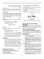
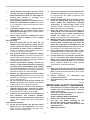
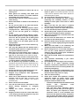
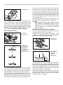
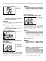
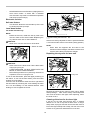
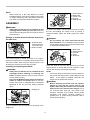
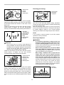
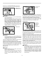
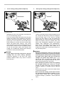
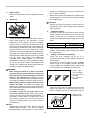
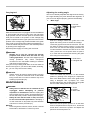
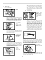
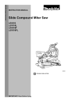
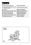
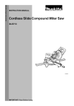
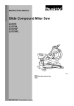
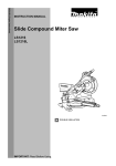
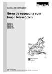
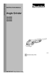
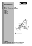
2.
Make sure that the pointer on the arm point to
0° on the bevel scale on the arm holder. If
they do not point to 0°, loosen the screw
which secure the pointer and adjust it so that
it will point to 0°.
45° bevel angle
Bevel angle
(1) 0° bevel angle
1. Lever
2. Arm
(2)
1
2
1. Right 45 ゚ bevel
angle adjusting
bolt
2. Left 45 ゚ bevel
angle adjusting
bolt
011413
Push the carriage toward the guide fence and
tighten the locking screw to secure the
carriage. Lower the handle fully and lock it in
the lowered position by pushing in the stopper
pin. Loosen the lever at the rear of the tool.
1
1
2
011381
Adjust the 45° bevel angle only after
performing 0° bevel angle adjustment. To
adjust left 45° bevel angle, loosen the lever
and tilt the blade to the left fully. Make sure
that the pointer on the arm points to 45° on
the bevel scale on the arm holder. If the
pointer does not point to 45°, turn the 45°
bevel angle adjusting bolt on the right side of
the arm holder until the pointer points to 45°.
To adjust the right 45° bevel angle, perform
the same procedure as that described above.
1. 0 ゚ adjusting
bolt
2. Left 45 ゚ bevel
angle adjusting
bolt
2
011379
Turn the hex bolt on the right side of the arm
two or three revolutions counterclockwise to
tilt the blade to the right.
1
2
1. Triangular rule
2. Saw blade
3. Top surface of
turn table
3
007834
Remove and check the carbon brushes regularly.
Replace when they wear down to 3 mm in length. Keep
the carbon brushes clean and free to slip in the holders.
Both carbon brushes should be replaced at the same
time. Use only identical carbon brushes.
001819
Carefully square the side of the blade with the
top surface of the turn base using the
triangular rule, try-square, etc. by turning the
hex bolt on the right side of the arm clockwise.
Then tighten the lever securely.
1
2
1. Screwdriver
2. Brush holder cap
1. Screw
2. Pointer
3. Bevel scale
1
2
010412
Use a screwdriver to remove the brush holder caps. Take
out the worn carbon brushes, insert the new ones and
secure the brush holder caps.
3
011342
20
After use
After use, wipe off chips and dust adhering to the
tool with a cloth or the like. Keep the blade guard
clean according to the directions in the previously
covered section titled "Blade guard". Lubricate the
sliding portions with machine oil to prevent rust.
•
When storing the tool, pull the carriage toward you
fully.
To maintain product SAFETY and RELIABILITY, repairs,
any other maintenance or adjustment should be
performed by Makita Authorized Service Centers, always
using Makita replacement parts.
•
OPTIONAL ACCESSORIES
WARNING:
These Makita accessories or attachments are
recommended for use with your Makita tool
specified in this manual. The use of any other
accessories or attachments may result in serious
personal injury.
•
Only use the Makita accessory or attachment
for its stated purpose. Misuse of an accessory or
attachment may result in serious personal injury.
If you need any assistance for more details regarding
these accessories, ask your local Makita Service Center.
•
Steel & Carbide-tipped saw blades
•
Miter saw blades
For smooth and precise cutting in various materials.
Combination
General purpose blade for fast and smooth rip,
crosscuts and miters.
Crosscutting
For smoother cross grain cuts. Slices cleanly
against the grain.
Fine cross cuts
For sand-free cuts cleanly against the grain.
Non-ferrous metals For miters in aluminum, copper, brass, tubing,
and other non-ferrous metals.
miter saw blades
006526
•
•
•
•
•
•
•
•
Sub-fence R
Vise assembly (Horizontal vise)
Vertical vise
Socket wrench with hex wrench on its other end
Holder
Dust bag
Elbow
Triangular rule
NOTE:
•
Some items in the list may be included in the tool
package as standard accessories. They may differ
from country to country.
21
22
23
Makita Jan-Baptist Vinkstraat 2, 3070, Belgium
Makita Corporation Anjo, Aichi, Japan
JM2328D030
www.makita.com
24