1
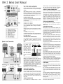
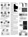
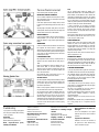
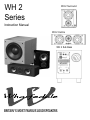
WH 2
Series
WH 2 Surround
Instruction Manual
WH 2 Centre
WH 2 Sub Bass
BRITAIN'S MOST FAMOUS LOUDSPEAKERS
IMPORTANT SAFETY PRECAUTIONS - PLEASE READ CAREFULLY!
CAUTION
RISK OF ELECTRIC SHOCK DO NOT OPEN!
The lightning flash with arrowhead symbol, within an equilateral triangle, is intended to alert the
user to the presence of uninsulated dangerous voltage within the product’s enclosure that may
be of sufficient magnitude to constitute a risk of electric shock to persons.
!
The exclamation point within an equilateral triangle is intended to alert the user to thepresence
of important operating and maintenance (servicing) instructions in the literature accompanying
the appliance.
Read Instructions: All the safety and operating instructions should be read before the product is operated.
Retain Instructions: The safety and operating instructions should be retained for future reference.
Heed Warnings: All warnings on the product and in the operating instructions should be adhered to.
Follow Instructions: All operating and use instructions should be followed.
Cleaning: Unplug this product from the wall outlet before cleaning. Do not use liquid cleaners or aerosol
cleaners. Use a damp cloth for cleaning.
Attachments: Do not use attachments not recommended by the product manufacturer as they may
cause hazards.
Water and Moisture: Do not use this product near water - for example, near a bath tub, wash bowl,
kitchen sink, or laundry tub, in a wet basement; or near a swimming pool; and the like.
Accessories: Do not place this product on an unstable cart, stand, tripod, bracket, or table. The product may
fall, causing serious injury to a child or adult, and serious damage to the product. Use only with a cart, stand, tripod,
bracket or table recommended by the manufacturer, or sold with the product. Any mounting of the product should
follow the manufacturer's instructions, and should use a mounting accessory recommended by the manufacturer.
Moving the Product: A product and cart combination should be moved with care. Quick stops,
excessive force, and uneven surfaces may cause the product and cart combination to overturn.
Ventilation: Slots and openings in the cabinet are provided for ventilation and to ensure reliable
operation of the product and to protect it from overheating, and these openings must not be blocked or
covered. The openings should never be blocked by placing the product on a bed, sofa, rug, or other similar
surface. This product should not be placed in a built-in installation such as a bookcase or rack unless proper
ventilation is provided or the manufacturer's instructions have been adhered to.
Power Supply Cords: Power supply cords should be routed so that they are not likely to be walked
on or pinched by items placed upon or against them, paying particular attention to cords at plugs,
convenience receptacles, and the point where they exit from the product.
Power Sources: This product should be operated only from the type of power source indicated on the
marking label. If you are not sure of the type of power supply to your home, consult your product dealer or
local power company. For products intended to operate from battery power, or other sources, refer to the
operating instructions.
Polarisation: This product is equipped with a polarized alternating-current line plug (a plug having one
blade wider than the other). This plug will fit into the power outlet only one way. This is a safety feature. If
you are unable to insert the plug fully into the outlet, try reversing the plug. If the plug should still fail to fit,
contact your electrician to replace your obsolete outlet. Do not defeat the safety purpose of the polarized plug.
Lightning: For added protection for this product during a lightning storm, or when it is left unattended
and unused for long periods of time, unplug it from the wall outlet and disconnect the antenna or cable
system. This will prevent damage to the product due to lightning and power-line surges.
Antenna Grounding: If an outside antenna or cable system is connected to the product, be sure the
antenna or cable system is grounded so as to provide some protection against voltage surges and built-up
static charges. Article 810 of the National Electrical Code, ANSI/NFPA 70, provides information with regard to
proper grounding of the mast and supporting structure, grounding of the lead-in wire to an antenna discharge
unit, size of grounding conductors, location of antenna-discharge unit, connection to grounding electrodes, and
requirements for the grounding electrode. (Refer to diagram)
Power Lines: An outside antenna system should not be located in the vicinity of overhead power lines
or other electric light or power circuits, or where it can fall into such power lines or circuits. When installing
an outside antenna system, extreme care should be taken to keep from touching such power lines or circuits
as contact with them might be fatal.
Example of Antenna Grounding as per
National Electrical Code ANSI/NFPA 70
Antenna lead in wire
Ground clamps
Antenna discharge unit
(NEC Section 810-20)
Grounding Conductors
(NEC Section 810-71)
Ground clamps
Electric service
equipment
Power service grounding electrode system
(NEC ART 250, Part H)
Overloading: Do not overload wall outlets, extension cords, or integral convenience receptacles as this
can result in a risk of fire or electric shock.
Object and Liquid Entry: Never push objects of any kind into this product through openings as
they may touch dangerous voltage points or short-out parts that could result in a fire or electric shock.
Heat: The product should be situated away from heat sources such as radiators, heat registers, stoves, or
other products (including amplifiers) that produce heat.
Servicing: Do not attempt to service this product yourself as opening or removing covers may expose you
to dangerous voltage or other hazards. Refer all servicing to qualified service personnel.
Damage Requiring Service: Unplug this product from the wall outlet and refer servicing to
qualified service personnel under the following conditions:
a) When the power supply-cord or plug is damaged
b) If liquid has been spilled, or objects have fallen into the product
c) If the product has been exposed to rain or water.
d) If the product does not operate normally by following the operating instructions. Adjust only those controls
that are covered by the operating instructions as an improper adjustment of other controls may result in damage
and will often require extensive work by a qualified technician to restore the product to its normal operation.
e) If the product has been dropped or damaged in any way.
f) When the product exhibits a distinct change in performance - this indicates a need for service.
Replacement Parts: When replacement parts are required, be sure the service technician has used
replacement parts specified by the manufacturer or have the same characteristics as the original part.
Unauthorised substitutions may result in fire, electric shock, or other hazards.
Safety Check: Upon completion of any service or repairs to this product, ask the service technician to
perform safety checks to determine that the product is in proper operating condition.
Introduction
INTRODUCTION
Congratulations on your purchase of dedicated audio-visual components from the Wharfedale WH 2
series. Before installing your loudspeakers please read these instructions in full.
UNPACKING
Carefully unpack each component taking care not to mark the surface. Inspect the product
and report any damage immediately to your dealer. Retain the packing so that the product
may be safely shipped in the future.
SOME IMPORTANT DO’S AND DON’TS
WARNING: To reduce the risk of fire or electrical shock do not expose this product to rain or
moisture. The product must not be exposed to dripping and splashing and no object filled
with liquids such as a vase of flowers should be placed on the product.
DO NOT allow foreign objects to fall into any of the units.
NO naked flame sources, such as candles must be placed on the product.
NEVER remove any components and refer all servicing to qualified personnel. This product
contains no user serviceable parts.
DO NOT change any connections to your loudspeakers unless your system is switched off.
DO NOT use your amplifier at its maximum volume setting. The resulting high levels of
distortion may damage your loudspeakers.
DO turn down the volume control on your amplifier or receiver before turning the equipment
on or off.
WALL OR CEILING MOUNTING: The product should be mounted to a wall or ceiling only as
recommended by the manufacturer.
CHOOSING AND PREPARING CABLES
Quality audio cable will usually give better results than ‘zip’ or ‘bell’ wire. Choose a quality
loudspeaker cable of suitable diameter - cable that is too thin may impair the system's bass
response. Audio cable is polarised, with two cores of different colours, or often a coloured
tracer. To prepare a cable, split the twin cores to a depth of about 25mm. Strip about 7mm of
insulation from each end. Stranded cable should be lightly twisted to gather the ends.
When connecting cables, ensure that there are no loose strands which may touch adjacent
terminals
ESSENTIAL INFORMATION FOR UK USERS
The mains lead on the WH 2 Sub Bass Loudspeaker may be supplied with a plug incorporating
a fuse, the value of which is indicated on the pin face of the plug. Should the fuse need to be
replaced, an ASTA or BSI approved BS1362 fuse must be used of the same rating. If the plug is
cut off it must NOT be re-used. Dispose of any such plug safely. There is a danger of electric
shock if a cut-off plug is inserted into a mains socket.
The wires in the mains lead are coloured in accordance with the following code:Green and
Yellow - Earth: Blue - Neutral: Brown - Live.
As the colours of the wires in the mains lead may not correspond with the markings
identifying the terminals in the replacement mains plug, proceed as follows:
The wire coloured Blue must be connected to the terminal marked with the letter "N" or
coloured Black. The wire coloured Brown must be connected to the terminal marked with the
letter "L" or coloured Red.The wire coloured Green and Yellow must be connected to the
terminal marked with the letter ‘E’,or coloured Green, or Green and Yellow, or marked with
the Earth symbol
WH 2 Series User Manual
WH 2 Sub Bass Loudspeaker
The WH 2 powered sub-bass unit uses a custom designed
long throw 250mm bass motor and a large 100 Watt power
amplifier.
When installing the unit allow a space of at least 450mm
between the subwoofer and the TV otherwise the colours on
the screen may be disturbed. If this occurs, switch the TV set
off and switch it on after 15 minutes. The internal circuits of
the TV set should restore normal colour.
POWER CONNECTIONS
This unit is set to the mains voltage marked on the amplifier
panel. Before connecting check that this voltage is correct for
your mains supply.
230 volt units: 220 - 240 volts
115 volt units: 110 - 120 volts
If you move to an area with a different mains supply, please
consult your Wharfedale dealer to arrange the conversion of
this product.
Although the power cord can be left plugged in, it should be
unplugged if the subwoofer is not going to be used for a long
period.
CAUTION (115 volt products only)
TO PREVENT ELECTRIC SHOCK MATCH THE WIDE BLADE OF
THE PLUG TO THE WIDE SLOT OF THE POWER OUTLET AND
FULLY INSERT THE PLUG.
SPEAKER LEVEL CONNECTIONS
If your amplifier does not have a line level subwoofer output,
you will need to feed the subwoofer from the Front
loudspeakers. For this you will need two extra twin core
cables.
Ensure your Front loudspeakers are correctly connected.
The Speaker Level
connectors are spring
terminals located on the
control panel. Press the
lever at the side of the
terminal and insert the
cable. Release the lever
and the wire is held firm.
Make sure that the
terminal grips the bare
wire.
There are two methods of connecting the subwoofer.
A Using one of the additional twin core cables, connect the
Left Speaker Terminals on the sub bass unit to the Front Left
speaker terminals on the amplifier. Connect the Red (+)
speaker terminal on the amplifier to the Red (+) terminal
on the subwoofer. Connect the Black (-) speaker terminal on
the amplifier to the Black (-) terminal on the subwoofer. Now
connect the Right Speaker terminals on the subwoofer to the
Front Right speaker terminals on the amplifier.
B Alternatively you may connect the subwoofer to the Front
speakers instead of to the amplifier.
LINE LEVEL CONNECTIONS
If your A V amplifier has a dedicated subwoofer line output
use this connection. Ensure you have a quality single
screened RCA phono cable. Connect this from the subwoofer
Output of the AV unit to the left Line Level Input socket on
the subwoofer. Ensure that the plugs are fully inserted and
firmly seated.
STEREO CONNECTIONS
If your amplifier has a preamplifier output or a stereo
subwoofer output, use the connection shown in Figure 2.You
will need a stereo RCA phono cable. Only the specified
outputs should be used - a Tape output is NOT suitable.
PRE OUT - MAIN IN CONNECTIONS
If you use a stereo pre and power amplifier, or an amplifier
where the pre and main amplifier can be separated, connect
the subwoofer as shown in Figure 3. You will need two stereo
screened RCA phono cables. Remove the Pre-Main links on
your amplifier. Connect one RCA cable between the Pre Out
Sockets on the amplifier and the Line Level Inputs on the
subwoofer. Connect a second cable from the Line Level
Outputs of the subwoofer to the Main In sockets of the
amplifier. Do not mix up the Right and Left Channels!
USING TWO SUBWOOFERS
The figures illustrate some suggestions for wiring two
subwoofers. If you need further information consult your
dealer for advice.
POSITIONING THE UNIT
Although the unit may be placed almost anywhere in the
room, even behind the sofa or the TV set, we recommend that
it be placed in front of the listener and as central to the
listening position as possible. The subwoofer should not be
operated within 450mm of a television set as the drive unit
magnet may distort the picture.
We suggest you position the subwoofer about 20cm (8
inches) from the wall. Placing the unit close to the wall will
enhance the bass; placing it across the corner of the room
will increase the bass further, possibly at the expense of
clarity. Experiment with a variety of locations and sources
before making a final decision.
As the subwoofer is a powered unit there should be a mains
outlet within easy reach.
The bass ports are mounted at the rear of the subwoofer and
should not be obstructed by placing the unit against soft
furnishings. Do not place the subwoofer close to surfaces or
objects that may rattle. The floor under the subwoofer should
be sound with no loose floorboards, etc.
SETTING UP
Set the subwoofer power switch to OFF. Turn the system
Volume Control to minimum. Re-check all system connections.
Now connect the subwoofer power lead to the mains and
switch on the power. Set the subwoofer volume control to the
mid position (12o'clock) before proceeding.
VARIABLE CROSSOVER This control should initially be set to 150
Hz when the subwoofer is used with small bookshelf speakers
and to 80 Hz when used with large floor standing speakers.
PHASE SWITCH The Phase switch should be initially set to 0°.
FINE TUNING
Switch on the subwoofer power switch and check that the
power indicator on the front of the cabinet glows. Now switch
on the system.
Play a programme with extended bass and set the system
volume to a reasonable level. Adjust the subwoofer volume
control to produce the desired level of bass. Do not overdo
things!
If the bass is indistinct or lacks depth, the Phase control may
need adjustment. Listen carefully to a programme with
extended bass and switch the Phase switch in and out.
Choose the setting which produces the most bass at the
listening position.
The Crossover control can now be fine tuned by adjusting the
bass output for optimum performance.
WH 2 Centre Loudspeaker
The Wharfedale WH 2
Centre Speaker
Centre speaker is a
Positioning
dedicated centre
channel unit designed
for mounting
preferably above, or
below, a TV screen. If
the unit is mounted
on top of the
television, move it
forward so that the
front grilles are level
with or slightly in
front of the screen.
This will reduce sound
reflections from the
top of the cabinet.
The loudspeaker
should be located on
a stable flat surface to avoid any danger of movement
when it is vibrated by high sound levels.
The speaker is supplied with four self-adhesive feet. Apply
one to each bottom corner of the unit before mounting.
Preparing
Speaker
Cables
Connecting
Speaker
Cables
Centre Channel Connections
CONNECTION
You will need a single length of twin core cable. Connect
the red (+) terminal of the centre unit to the red (+)
terminal of the amplifier’s centre channel output. Connect
the Black (-) terminal of the centre unit to the
corresponding Black (-) terminal of the amplifier. The
connection panel uses screw terminals - the drawing
opposite illustrates the connection method.
WH 2 Rear Loudspeakers
The Wharfedale WH 2 rear speakers are bipolar units
designed for wall mounting and intended for use solely as
rear effects speakers.
In a Home Theatre system, the directional cues come from
the front and centre channels. The rear channels provide
ambience and rear perspective and for this purpose a
bipolar design with its mix of direct and reflected sound
is ideal. To aid this effect we recommend placing the WH 2
rear speakers in a high position behind the listener.
Wall-mounting the
WH 2 Rear
Loudspeakers
PREPARATION
Each speaker is supplied with four self-adhesive feet.
Apply one to each rear corner before mounting.
CONNECTIONS
You will need one length of twin core cable per speaker.
Connect the red (+) terminal of the left rear unit to the
red (+) terminal of the amplifier’s left rear channel
output. Connect the Black (-) terminal of this unit to the
corresponding Black (-) terminal of the amplifier. Repeat
for the Right speaker. The connection panel uses screw
terminals - the drawing above illustrates the connection.
MOUNTING
Connect the cable to the speaker. Site the speakers about
600 mm above the listening position and 2.5-3.5 metres
apart, central to the listener and behind the listening
position. Ensure that the wall is sound and can support
the product. Fix a suitable screw firmly to the wall leaving
a stub of 5mm protruding from the wall. Align the hole in
the mounting bracket over the screw head and carefully
lower the unit onto the screw. The speaker should now be
securely attached with the feet against the wall. Now
connect the speakers to the amplifier.
Rear Channel Connections
The Home Theatre Environment
A Home Theatre system is illustrated opposite.
FRONT AND CENTRE CHANNELS
The front channel loudspeakers should be placed on either
side of the television screen, 2 to 3 metres apart. and rotated
slightly towards the listeners.
As the Centre speaker carries the dialogue effects, it should
be placed central to the listening position and close to the TV
screen.
Operating height is important. Ideally, the front and centre
channel speakers should be operated at the same height and
with the tweeters at ear level to a seated listener.
REAR CHANNELS
If the rear channels are WH 2 Surround units, mount them as
already described. If you use other units, we recommend
placing the speakers in a high position. angled towards the
listener.
SUBWOOFER
As the ear is unable to detect the direction from which deep
bass originates, this allows freedom in positioning the
subwoofer. Varying the distance from the wall will alter the
amount of bass. Some prefer to place the subwoofer against a
corner of the room. This arrangement gives more bass at the
possible expense of clarity.
LOUDSPEAKER SIZES
Many digital AV Processors require you to specify the size of
speakers in the various channels. These are usually ‘Large’ or
‘Small’.
Unless your loudspeakers are large floor standing units, you
should choose 'Small' for the Front channels, as the
subwoofer is going to be better at providing clean, deep and
louder bass. Choose 'Small' for the surround channels and
also for the Centre channel.
Set the ‘Subwoofer’ option on the processor to 'On' or 'Yes'.
This will route all the deep bass to the subwoofer.
SETTING LEVELS
Once the loudspeaker settings have been finalised, put the AV
amplifier into its “Test” mode (see instructions supplied with
your processor.) Adjust the levels until all channels are
reproduced at equal loudness.
NOTE: On some programme material the surround channel
may seem lower than the front. Do not readjust this level.
You may, however, need to adjust the subwoofer output level.
Avoid setting too high a level or you will swamp the sound
with bass which be tiring to listen to and may limit the
subwoofer’s ability to respond to large bass transients. Set a
sensible level going into the subwoofer from the AV processor.
The volume control on the subwoofer should be between 12
o’clock and 3 o’clock when the system as a whole is playing
moderately loudl
Troubleshooting
If your system is not working properly please
work through this checklist before returning
a unit to your dealer.
No Sound
System not switched on
Speaker cables shorting terminals out
Bass reproduction poor,
muddy or indistinct.
Subwoofer not switched on
Subwoofer phase incorrect
Subwoofer crossover set too low
Bass distortion at low volume
Subwoofer level set too high
LFE level set too high
Excessive or distorted bass at
high volume.
System level set too high
Bass control set too high
LFE
The Low Frequency Effects channel was designed as an
additional bass channel with its own dedicated subwoofer. In
practice however, if all the speakers are set to Small, the LFE
channel will be combined with the bass from other channels
and all this feeds into the subwoofer.When you set the LFE level
from your AV processor, use care with this setting as the LFE
channel may contain powerful low frequencies which, although
normal in a cinema, may overload a domestic subwoofer.
If, during a programme, you hear popping or thumping
noises coming from the subwoofer, immediately turn the AV
Processor's volume level down and then back off the LFE
level. If this does not cure the problem, back off the volume
level at the subwoofer.
Please read the relevant sections of your AV amplifier manual
and familiarise yourself with the various issues. If you are
unsure, consult your dealer for help.
MAINS OPERATION
When the system is not in use we suggest you switch off the
subwoofer to protect it from switching noises caused by
domestic appliances, etc. The best practice is to switch the
complete system on and off from a central point. If you play
the system with the subwoofer switched off no damage will
result but you will get no bass!
Always turn the main volume control to minimum when you
switch the equipment on or off.
CONNECTING WIRES
When wall mounting a loudspeaker the connecting cables may
be unacceptably obvious. It may be less obtrusive to route
cables from the loudspeaker to the ceiling and then within or
immediately underneath the ceiling or coving. The cable may
then return to floor level at a convenient room corner.
CARE AND MAINTENANCE
If you play the speakers with the grilles off exercise great
care. NEVER touch the drive units which are easily damaged.
The loudspeaker cabinets can be cleaned with a damp cloth
or with a spray furniture polish and a soft cloth. Apply the
spray sparingly to the cloth and then polish the cabinet.
Never apply spray directly to the cabinet.
GUARANTEE & SERVICE
In the unlikely even that your unit develops a fault you
should return it to your Wharfedale dealer using the original
packing to ensure safe shipping.
The terms of your guarantee may vary from country to
country but in all locations the guarantee excludes:
All damage caused through accident, misuse, wear and tear,
neglect, incorrect installation, adjustment or repair by
unauthorised personnel.
Liability for damage or loss occurring in transit to or from
the purchaser.
Wharfedale will not be liable for any consequential damage,
loss or injury, arising from or in conjunction with this
equipment.
Subwoofer too close to room corners
Distortion or rattling at high
volume
System level set too high
Objects placed on or near subwoofer
Popping sounds or thumps
from the subwoofer
System level set too high
Subwoofer level set too high
LFE level set too high
Poor localisation of effects or
dialogue
One or more loudspeakers is out of phase:
(Read the manual for the correct connection
procedure)
TV picture is distorted
Subwoofer is too close to the TV. Switch off
the system and TV. Move subwoofer away.
Leave 20 mins. Switch on again.
Specifications and Service
WH 2
Surround
WH 2
Centre
6 Ohms
6 Ohms
120 Watts
120 Watts
88 dB
89 dB
Frequency Response
80 - 20 kHz
80 - 20 kHz
Bass Unit
2 x 100 mm
2 x 100 mm
2 x 28 mm Dome
28 mm Dome
244x 225x 126
9.6 x 8.9 x 5.0
125 x 420 x 150
4.9 x 16.5 x 5.9
Nominal Impedance
Power Handling
Sensitivity (1W@1m)
Treble Unit
Dimensions Overall
H x W x D mm
H x W x D inches
WH 2
Sub Bass
Line Input Sensitivity
Amplifier Power
250 mV for 75 W
100 Watts
Maximum Output (at 1m)
87 dB
LF Response
28 Hz
Crossover Range
Drive Unit
Dimensions Overall
H x W x D mm
H x W x D inches
70 - 170 Hz
250 mm
430 x 320 x 400
16.9 x 12.6 x 15.7
Service & Information
Wharfedale speakers are compatible with 4 and 8 Ohm amplifiers
Authorised Wharfedale Service Centres
USA
IAG America, Inc.
180 Kerry Place
Norwood
MA 02062
Tel: +1 781 440 0888
CANADA
Korbon Trading Ltd
6800 Kitimat Road
Units 19-20
Mississauga
Ontario
Tel: +1 905 567 1920
U.K.
Wharfedale International Ltd.
IAG House, Sovereign Court,
Ermine Business Park, Huntingdon,
Cambs PE29 6XU, England.
Tel:+44 (0)1480 447700
Fax: +44 (0)1480 43176
For information on authorised service centres worldwide contact
Wharfedale International in the U.K.
A worldwide distributor list is available on the Wharfedale website:
www.wharfedale.co.uk
The name WHARFEDALE' is a registered trademark of Wharfedale
International Limited.
Wharfedale has a policy of continuous product development and reserves
the right to change specification without notice.
Wharfedale is a member of the International Audio Group.
1932
Loudspeaker Manufacturers since 1932
In 1932, when Gilbert Briggs founded the Wharfedale Wireless
Works, his company was at the leading edge of an exciting new
technology which was dedicated to bringing the pleasure of music
and entertainment to a wide range of people. As the technology
advanced Wharfedale gave many music lovers their first taste of
High Fidelity, mounting a series of live sound demonstrations which
excited the audio world and heralded the era of the modern hi-fi
loudspeaker.
Today Wharfedale still takes the same uncompromising approach to
the design and manufacture of every loudspeaker system, using high
quality components and state-of-the-art testing to ensure consistently
high performance. And that means that you can continue to count on
the quality of all Wharfedale products.