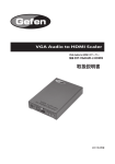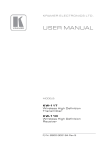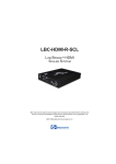
1
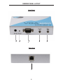
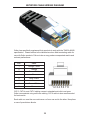
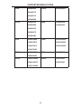
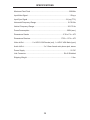
®
1:2 VGA Audio
Over Cat5
EXT-VGAAUD-CAT5-142
User Manual
www.gefen.com
ASKING FOR ASSISTANCE
Technical Support:
Telephone
Fax
(818) 772-9100
(800) 545-6900
(818) 772-9120
Technical Support Hours:
8:00 AM to 5:00 PM Monday thru Friday.
Write To:
Gefen, LLC
c/o Customer Service
20600 Nordhoff St
Chatsworth, CA 91311
www.gefen.com
[email protected]
Notice
Gefen, LLC reserves the right to make changes in the hardware, packaging, and
any accompanying documentation without prior written notice.
1:2 VGA Audio over CAT5 is a trademark of Gefen, LLC
© 2011 Gefen, LLC. All rights reserved.
All trademarks are the property of their respective owners.
Rev A2
CONTENTS
1
Introduction
2
Operation Notes
3
Features
4
Sender Panel Layout
5
Sender Panel Descriptions
6
Receiver Panel Layout
7
Receiver Panel Descriptions
8
Connecting And Operating The 1:2 VGA Audio over CAT5
9
Adjusting The Video Quality
10 Network Cable Wiring Diagram
11 Supported Resolutions
11 Specifications
13 Warranty
INTRODUCTION
Congratulations on your purchase of the 1:2 VGA Audio over CAT5. Your
complete satisfaction is very important to us.
Gefen
Gefen delivers innovative, progressive computer and electronics add-on solutions
that harness integration, extension, distribution and conversion technologies.
Gefen’s reliable, plug-and-play products supplement cross-platform computer
systems, professional audio/video environments and HDTV systems of all sizes
with hard-working solutions that are easy to implement and simple to operate.
The Gefen 1:2 VGA Audio over CAT5
The 1:2 VGA Audio over CAT5 extends and duplicates your audio and VGA video
signals at distances of up to 1000 feet away. Remote A/V signals are received
from the 1:2 VGA Audio over CAT5 Sender via industry-standard CAT5 network
cables.
The 1:2 VGA Audio over CAT5 will extend analog VGA as well as analog Audio
and provide two full sets of A/V signal output on the receiving end.
How It Works
The 1:2 VGA Audio CAT5 Distribution Amplifier Sender unit is placed at the
source location. A standard CAT5 cable is run from the 1:2 VGA Audio over CAT5
Sender up to 1000 feet to the 1:2 VGA Audio over CAT5 Receiver unit. The 1:2
VGA Audio over CAT5 Receiver unit connects to your remote video displays and
audio inputs. A microphone jack provides bi-directional audio support.
1
OPERATION NOTES
READ THESE NOTES BEFORE INSTALLING OR
OPERATING THE 1:2 VGA AUDIO OVER CAT5
•
Use only industry standard Category-5 Enhanced (CAT-5e) cable to operate
the 1:2 VGA Audio over CAT5. Cat-6 cables can also be used.
•
Both the sending and receiving units must be powered with the supplied power
adapters for proper operation.
•
Field termination of CAT5e cabling must adhere to the TIA/EIA-568-B
specification. Please see page 10 for additional information.
2
FEATURES
Features
•
Supports up to 1920x1200 VGA video at 60 Hz
•
Supports analog L+R audio
•
No Loss of Quality
•
Simple plug-and-play installation
•
Equalizations for different CAT-5 skews
Package Includes
(1) 1:2 VGA and Audio over CAT5 Extender Sender
(1) 1:2 VGA and Audio over CAT5 Extender Receiver
(2) 5V DC Power Supplies
(1) 6 ft. VGA Cable (M-F)
(1) 6 ft. 3.5mm mini-stereo audio cable
(1) Quick-Start Guide
3
SENDER PANEL LAYOUT
Front Panel
1
2
4
3
Rear Panel
6
4
5
SENDER PANEL DESCRIPTIONS
1
5V DC Power Input
Connect the included 5V DC power supply input this port. Once this has been
properly connected the power LED will become active.
2
Power LED Indicator
This LED will become active once the included 5V DC power supply is properly
connected.
3
VGA Input
Connect the VGA source device to this input.
4
3.5mm Mini-Phono Jack Analog Stereo Input
Connect the VGA source’s analog audio to this input. This will send audio from
the source location to the receiver location.
5
3.5mm Mini-Phono Jack Analog Stereo Output (Mic. Out)
This port will output audio that is sent from the receiving location. This port will
receive audio from a microphone device that is connected to the receiver.
6
CAT-5 Port
Connect a CAT-5e cable between the CAT-5 ports on both the sending and
receiving units.
5
RECEIVER PANEL LAYOUT
Front Panel
1 2 3
4 5 6
Back Panel
7
8
9
10
6
11
12
13
RECEIVER PANEL DESCRIPTIONS
1
Red Color Shift Trim Pot
Adjust this Trim Pot to eliminate any shift of the red color in the video output.
Please see page 9 for detailed instructions on the usage.
2
Green Color Shift Trim Pot
Adjust this Trim Pot to eliminate any shift of the green color in the video output.
Please see page 9 for detailed instructions on the usage.
3
Blue Color Shift Trim Pot
Adjust this Trim Pot to eliminate any shift of the blue color in the video output.
Please see page 9 for detailed instructions on the usage.
4
Brightness Trim Pot
Adjust this Trim Pot to brighten/darken the output video. Please see page 9 for
detailed instructions on the usage.
5
Focus Trim Pot
Adjust this Trim Pot to blur/sharpen the output video. Please see page 9 for
detailed instructions on the usage.
6
Power LED Indicator
This LED will become active once the included 5V DC power supply is properly
connected.
7
5V DC Power Input
Connect the included 5V DC power supply input this port. Once this has been
properly connected the power LED will become active.
8
VGA Output 1
Connect a VGA capable device to this output.
9
VGA Output 2
Connect a VGA capable device to this output. This output will mirror the video
from VGA Output 1.
10 3.5mm Mini-Phono Jack Analog Stereo Output 1
Connect this output to either amplified speakers or an audio amplifier. Audio
from the sender will be sent from the source location to the receiver location.
11 3.5mm Mini-Phono Jack Analog Stereo Output 2
Connect this output to either amplified speakers or an audio amplifier. Audio
from the sender will be sent from the source location to the receiver location.
12 3.5mm Mini-Phono Jack Analog Stereo Input
Connect an analog stereo device, such as a microphone, to this input port.
Audio will be sent to the sender and output via the “Mic. Out” port.
13 CAT-5 Port
Connect a CAT-5e cable between the CAT-5 ports on both the sending and
receiving units.
7
CONNECTING AND OPERATING THE 1:2 VGA AUDIO OVER CAT5
How to Connect the 1:2 VGA Audio over CAT5
1.
Connect the VGA video source to the VGA Audio Over CAT5 sending unit
using the supplied VGA cable.
2.
Connect the audio source to the VGA Audio Over CAT5 sender unit using
the user supplied 3.5mm mini-phono jack stereo cable.
3.
Optionally, connect the 3.5mm mini-phono jack stereo output from the
sender to a compatible device using a user supplied 3.5mm mini-phono jack
stereo cable.
Example: Use a microphone at the receiver’s location in this example
scenario. Connect a microphone to the 3.5mm mini-phono jack input on
the receiver. Then use a 3.5mm mini-phono jack stereo cable to connect
the sender’s output to a microphone input port on a computer or amplified
receiver.
4.
Connect up to 2 VGA displays to the 1:2 VGA Audio over CAT5 receiving unit
using user supplied VGA cables.
NOTE: Both outputs are mirrored images of the VGA video source.
5.
Connect up to 2 of the 3.5mm mini-phono jack audio outputs on the 1:2
VGA Audio over CAT5 receiving unit to amplified audio devices using user
supplied 3.5mm mini-phono jack stereo audio cables.
6.
Optionally, connect a 3.5mm mini-phono jack stereo audio device to the
receiver for transmission back to the sender’s location. Please see the
example in step 3 for an example scenario.
7.
Connect the 1:2 VGA Audio over CAT5 sending and receiving units together
using a single CAT-5, CAT-5e or CAT-6 cable (terminated according to the
TIA/EIA-568-B specification).
8.
Connect the included 5V DC power adapters to both the sending and
receiving units.
9.
Power on all displays first, and then the source.
8
ADJUSTING THE VIDEO QUALITY
Focus & Brightness
The 1:2 VGA Audio over CAT5 receiving unit can adjust both the brightness and
focus of the reproduced video signal. Differences in cable skew and distance are
factors that can affect these settings. To adjust these settings and tune the video
signal please use the steps below.
Brightness
If the image appears too dim or too bright, adjust the brightness Trim Pot on the
front of the 1:2 VGA Audio over CAT5 Receiver.
Insert a small flathead device into the brightness Trim Pot hole and turn the Trim Pot
in either a clockwise or counterclockwise direction. Turn the Trim Pot in very small
increments until the desired brightness is reached.
Focus
If the image is out of focus or if the image appears too sharp, adjust the focus Trim
Pot on the front of the 1:2 VGA Audio over CAT5 Receiver.
Insert a small flathead device into the focus Trim Pot hole and turn the Trim Pot in
either a clockwise or counterclockwise direction. Turn the Trim Pot in very small
increments until the image clears and there is not blurriness or smearing.
Color Shifting
The 1:2 VGA Audio over CAT5 receiving unit can also adjust each color
component (red, green, and blue) individually if color shifting appears on the
reproduced video signal. Differences in cable skew and distance are factors
that can affect these settings. To adjust these settings and tune the video signal
please use the steps below.
If an individual color, or multiple colors, appear to be shifted in the reproduced video
signal, please use the individual color Trim Pots on the 1:2 VGA Audio over CAT5
receiver to fix the convergence issues.
Insert a small flathead device into the desired color’s Trim Pot hole and turn the Trim
Pot in either a clockwise or counterclockwise direction. Turn the Trim Pot in very
small increments until the image clears and the convergence has been corrected.
Repeat this process for any of the three component colors.
9
NETWORK CABLE WIRING DIAGRAM
Gefen has specifically engineered their products to work with the TIA/EIA-568-B
specification. Please adhere to the table below when field terminating cable for
use with Gefen products. Failure to do so may produce unexpected results and
reduced performance.
Pin
Color
1
Orange / White
2
Orange
3
Green / White
4
Blue
5
Blue / White
6
Green
7
Brown / White
8
Brown
12345678
CAT-5, CAT-5e, and CAT-6 cabling comes in stranded and solid core types.
Gefen recommends using solid core cabling. CAT-6 cable is also recommended
for best results.
Each cable run must be one continuous run from one end to the other. No splices
or use of punch down blocks.
10
SUPPORTED RESOLUTIONS
VGA
640x480/60
UXGA
1600x1200/60
480p
720X480p/59
640x480/72
640x480/75
640X480/85
SVGA
800x600/56
800X600/60
720X480p/60
800X600/72
800X600/75
800X600/85
XGA
1024X768/60
1080i
1920X1080i/50
1024X768/70
1920X1080i/59
1024x768/75
1920X1080i/60
1024x768/85
WXGA
1280X960/60
576p
720X576p/50
Native
1366X768/50
1280x960/85
SXGA
1280X1024/60
1280X1024/75
1366X768/60
1280X1024/85
11
SPECIFICATIONS
Maximum Pixel Clock .................................................................................350 MHz
Input Video Signal ....................................................................................... 1.2V p-p
Input Sync Signal .................................................................................5V p-p (TTL)
Horizontal Frequency Range ................................................................. 15-70 KHz
Vertical Frequency Range ..................................................................... 30-170 Hz
Power Consumption ...............................................................................20W (max.)
Dimensions Sender ..................................................................... 9”W x 1”H x 4”D
Dimensions Receiver ............................................................. 17”W x 1.3”H x 4”D
Video In/Out ................. 2 x HD15 VGA Female (out), 1 x HD15 VGA Male (input)
Audio In/Out ........................................ 3 x 3.5mm female mini-phone jack, stereo
Power Supply .............................................................................................. 5V DC
Link Connector .............................................................................. RJ-45 Shielded
Shipping Weight ............................................................................................ 5 lbs.
12
WARRANTY
Gefen warrants the equipment it manufactures to be free from defects in material
and workmanship.
If equipment fails because of such defects and Gefen is notified within two (2)
years from the date of shipment, Gefen will, at its option, repair or replace the
equipment, provided that the equipment has not been subjected to mechanical,
electrical, or other abuse or modifications. Equipment that fails under conditions
other than those covered will be repaired at the current price of parts and labor in
effect at the time of repair. Such repairs are warranted for ninety (90) days from
the day of reshipment to the Buyer.
This warranty is in lieu of all other warranties expressed or implied, including
without limitation, any implied warranty or merchantability or fitness for any
particular purpose, all of which are expressly disclaimed.
1.
Proof of sale may be required in order to claim warranty.
2.
Customers outside the US are responsible for shipping charges to and from
Gefen.
3.
Copper cables are limited to a 30 day warranty and cables must be in their
original condition.
The information in this manual has been carefully checked and is believed to
be accurate. However, Gefen assumes no responsibility for any inaccuracies
that may be contained in this manual. In no event will Gefen be liable for
direct, indirect, special, incidental, or consequential damages resulting from
any defect or omission in this manual, even if advised of the possibility of such
damages. The technical information contained herein regarding the features and
specifications is subject to change without notice.
For the latest warranty coverage information, refer to the Warranty and Return
Policy under the Support section of the Gefen Web site at www.gefen.com.
PRODUCT REGISTRATION
Please register your product online by visiting the Register Product page
under the Support section of the Gefen Web site.
13
Rev A 2
20600 Nordhoff St., Chatsworth CA 91311
1-800-545-6900
818-772-9100
www.gefen.com
Pb
This product uses UL listed power supplies.
fax: 818-772-9120
[email protected]