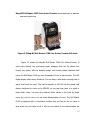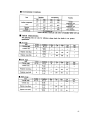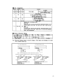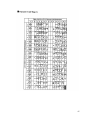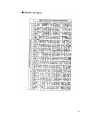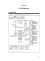
1
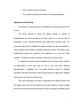
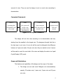
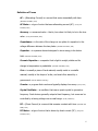
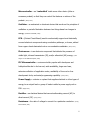
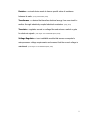
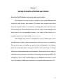
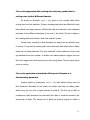
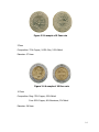
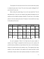
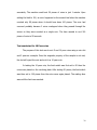
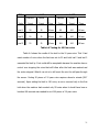
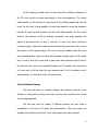
Coin Sorting and Counting Machine By Ray Anthony C. Reyes Mark Phillip P. Tan Timothy Jude O. Torralba A Design Report Submitted to the School of Electrical Engineering, Electronics and Communications Engineering, and Computer Engineering in Partial Fulfillment of the Requirements for the Degree Bachelor of Science in Computer Engineering Mapua Institute of Technology November 2008 i ii TABLE OF CONTENTS TITLE PAGE i APPROVAL SHEET ii TABLE OF CONTENTS iii LIST OF TABLES v LIST OF FIGURES vi ABSTRACT vii Chapter 1: DESIGN BACKGROUND AND INTRODUCTION 1 Design Setting Statement of the Problem Objective of the Design Significance of the Study Conceptual Framework Scope and Delimitation Definition of Terms Chapter 2: REVIEW OF RELATED LITERATURE AND STUDIES How the Philippine coin sorter and counter works Coin sorting apparatus with rotating disc stationary guide plate for sorting coins by their different diameter Coin sorter apparatus and method utilizing coin thickness as a discriminating parameter Coin counter The Philippine Peso coins Mag-Nif Roll Master CLXX Coin Sorter/Counter 1 2 2 3 4 4 6 10 10 11 11 12 13 15 Chapter 3: DESIGN METHODOLOGY AND PROCEDURES 17 Design Methodology Design Procedure Hardware Design Block Diagram 17 18 18 20 iii Schematic Diagram List of Materials 21 22 Software Design Prototype Development Chapter 4: TESTING, PRESENTATION AND INTERPRETATION OF DATA Test Test Test Test Test Test conducted for 25 centavo coins conducted for 1 peso coins conducted for 5 peso coins conducted for 10 peso coins conducted for mixed coins for Manual Testing Chapter 5: CONCLUSION AND RECOMMENDATION Conclusion Recommendation 23 24 26 26 27 29 30 32 33 35 35 36 BIBLIOGRAPHY 37 APPENDICES 38 Appendix Appendix Appendix Appendix Appendix A B C D E 38 40 50 52 54 iv LIST OF TABLES Table Table Table Table Table Table 4.1: 4.2: 4.3: 4.4: 4.5: 4.6: Testing for 25 centavo coins Testing for 1 Peso coins Testing for 5 Peso coins Testing for 10 Peso coins Testing for Mixed Coins Manual Testing 27 28 29 31 32 34 v LIST OF FIGURES Figure Figure Figure Figure Figure Figure Figure Figure Figure Figure 1.1 2.1 2.2 2.3 2.4 2.5 3.1 3.2 3.3 3.4 Conceptual Framework A sample of 25 centavo coin A sample of 1 Peso coin A sample of 5 Peso coin A sample of 10 Peso coin Mag-Nif Roll Master CLXX Coin Sorter/Counter full stack Block Diagram of the Design Circuit Diagram of the Design List of Materials Used System Flowchart 4 13 13 14 14 15 20 21 22 23 vi ABSTRACT The design was entitled Coin Sorting and Counting Machine for it is to sort and count the Philippine coin denomination except for the 5 and 10 centavo coins. This was done to be able to help different instituitions that deal with large number of coins in their daily operation. Some of these are banks, churches, charitable instituitions and the transport sector. The sorting part of the design is basically mechanical as it sorts the coins through their physical size then counts them as they pass through the phototransistor. After performing some tests with the Coin Sorting and Counting Machine, the group could say that an almost accurate and reliable machine was created as manifested by the results it made. Keywords: denomination, coin slot, rotating plate, microcontroller vii Chapter 1 DESIGN BACKGROUND AND INTRODUCTION Design Setting In the Philippines, the first coins were used in 1861. Until now, people still use coins in their everyday lives. Ther are those that deal with coins everyday like banks, tranport groups, casinos, charitable instituitions and the like. Daily, banks produce and receive coins which they deliver to other establishments to supply their need for coins. Charitbale instituitions like churches gather coins from donations during mass. And in public transport sector, coins are widely used whether as fares or change. These establishments count and sort coins everyday. Without the use of machines that can handle large operations regarding coins, an establishment needs to hire an extra employee just to deal with coins or just count them manually where it could take too much of his time which could be used for other work. The design was developed to help the trade and industry in counting coins faster and easier. Using phototransistors, the design counts faster and more accurate because it is not sensitive to visible light. A PIC Microcontroller was used to determine the total number of coins, total amount per denomination and the total amount of all coins. A three-way switch is also used to stop the count every 50 or 100 coins or to continuously count. 1 It is surprising how people manage to sort and count coins especially in large quantity. The group thought of a design that would try to help and solve the problem of counting coins of large quantity. With the design, the group can help the trade and industry by providing a simple yet effective way of dealing with large quantity of coins and saving precious time which can be put to other work. Statement of the Problem Persons who manually sort and count coins of large quantity usually take too much of their time and may refrain themselves from doing other tasks. There are available coin sorters and counters in the market but are very expensive. The main problem of the study is to find a way to count and sort Philippine coins of different denominations in less time and with accuracy. Objective of the Design The general objective of the design was to develop a coin sorting machine that sorts and counts Philippine coins. The other specific objectives were as follows: 1. Use the PIC Microcontroller to program the machine to stop every 50 or 100 coins counted. 2. Provide more accuracy and reliability in counting coins. 3. Create a design with less cost and more simple. 2 4. Sort a variety of coins in less time. 5. To contribute something beneficial to the trade and industry. Significance of the Study This study is an improvement of the existing coin sorter being used in the country. The group wanted to share the design project to owners of establishments and small businesses by letting them try to use this kind of technology in their everyday dealings with sorting and counting coins. The proposed design will be affordable to ordinary people and can be applicable to various industries like banking, charitable institutions and etc. The design is also implemental because the equipment and materials to be used are locally available. The users also have an option to limit the coins to be sorted. To students, the design will be beneficial since it develops their creativity by improvising on their own way on how to sort and count different denominations of Philippine coin. The design would be helpful to students especially those who keep spare coins and store them in a piggy bank. Students will have an easier task of counting coins. The school especially the treasury department can directly benefit from the design since it can use the machine for its daily operation. A good example will be during the enrollment period when treasury personnel are handling large 3 amount of coins. They can use the design to sort or count coins according to denomination. Conceptual Framework INPUT SORT COUNT OUTPUT A rotating plate will hold the coins to be sorted The system will sort the coins according to their denominations Upon sorting the coins, the system will count the coins Display its total value and amount Figure 1.1 Conceptual Framework The design will sort the coins according to its denomination and size, starting from the smallest to the largest coin. The designers thought that this is the best way to sort coins. A coin slot will be used to distinguish the difference between a 5 peso coin and a 10 peso coin since they are similar in size. A sensor will be used to count the sum total of the coins and display the value to a Liquid Crystal Display (LCD) panel. Scope and Delimitations The features and capabilities of the design are the scope of the study: 1. The design can sort and count Philippine coin denominations, namely, 25 centavo coin, 1 peso coin, 5 peso coin and 10 peso coin only. 4 2. The rotating plate can only handle a certain weight for it to function properly, that is, approximately 30-40 coins at a time. 3. The number of pieces and corresponding value will be displayed using a Liquified Crystal Display (LCD). 4. The grand total also updates whenever any of the reset buttons is pressed. The sensor will count anything that passes through and count it. 5. The design can also be fitted with a battery to save the data and retain its value, but cannot run the motor with just a battery. There are the delimitations which the design cannot perform. 1. The machine cannot accept deformed coins and cannot recognize whether the coin is fake or genuine. For example, if a token was placed instead of a coin in the machine, the system would still sort it as long as it is the same size as the coins. 2. The display can only handle up to 4 digit numbers. 3. 5 centavo and 10 centavo coins can be sorted but not with perfect accuracy. 4. The coins once sorted and counted will be placed in a holding container randomly and not stacked. 5 Definition of Terms AC – (Alternating Current) is a current that varies sinusoidally with time. (Alexander and Sadiku, 2004) AC Motor – a type of motor that uses alternating current (AC). (Young and Freedman, 2000) Accuracy – a measured value – that is, how close it is likely to be to the true value. (Young and Freedman, 2000) Capacitance – is the ratio of the charge on one plate of a capacitor to the voltage difference between the two plates. (Alexander and Sadiku, 2004) Capacitor – is a passive element designed to store energy in its electric field. (Alexander and Sadiku, 2004) Ceramic Capacitor – a capacitor that is light in weight, stable and its change in temperature is predictable. (Alexander and Sadiku, 2004) Coin – is usually a piece of hard material, usually metal or a metallic material, usually in the shape of a disc, and most often issued by a government. (Merriam Webster Dictionary) Counter - a program that counts and typically displays how many. (Grout, 2007) Crystal Oscillator – an oscillator that uses a quartz crystal to generate a frequency. Such devices generally output a fixed frequency, but some can be controlled by a tuning voltage over a small range. (Purdie, 1998-2001) DC – (Direct Current) is a current that remains constant with time. (Alexander and Sadiku, 2004) DC Motor – a type of motor that is driven by direct current (DC). (Young and Freedman, 2000) 6 Denomination – a proper description of a currency amount, usually for coins or banknotes. (Merriam Webster Dictionary) Diode - comprises a section of N-type material bonded to a section of P-type material, with electrodes on each end. (Harris, 1998-2008) Electrolytic Capacitor – a type of capacitor that produces very high capacitance. (Alexander and Sadiku, 2004) Flowchart – is a graphical representation of a process such as a manufacturing operation or computer operation, indicating the various steps that are taken as the product moves along the production line or the problem moves through the computer. (Boilot, Gleason and Horn, 1979) Infrared - refers to energy in the region of the electromagnetic radiation spectrum at wavelengths longer than those of visible light, but shorter than those of radio waves. (Tech Target: The IT Media ROI Experts, 2008) LCD – (Liquid Crystal Display) a low-power flat-panel display used in many laptop computers, calculators and digital watches, made up of a liquid crystal that is sandwiched between layers of glass or plastic and becomes opaque when electric current passes through it. The contrast between the opaque and transparent areas forms visible characters. (Castellano, 2005) LED – (Light Emitting Diode) is a semiconductor device that emits visible light when an electric current passes through it. (Harris, 1998-2008) 7 Microcontroller - are "embedded" inside some other device (often a consumer product) so that they can control the features or actions of the product. (Grout, 2007) Oscillator – a mechanical or electronic device that works on the principles of oscillation: a periodic fluctuation between two things based on changes in energy. (Alexander and Sadiku, 2004) PCB – (Printed Circuit Board) used to mechanically support and electrically connect electronic components using conductive pathways, or traces, etched from copper sheets laminated onto a non-conductive substrate. (Grout, 2007) Photosensor - is an electronic component that detects the presence of visible light, infrared transmission (IR), and/or ultraviolet (UV) energy. (Tech Target: The IT Media ROI Experts, 2008) PIC Microcontroller – a microcontroller popular with developers and hobbyists alike due to its low cost, wide availability, large user base, extensive collection of application notes, availability of low cost or free development tools, and serial programming capability. (Grout, 2007) Power Supply – a device or system that supplies electrical or other types of energy to an output load or group of loads is called a power supply unit or PSU. (Floyd, 2003) Rectifier – an electrical device that converts alternating current (AC) to direct current (DC). (Floyd, 2003) Resistance – the ratio of voltage to current for a particular conductor. (Young and Freedman, 2000) 8 Resistor – a circuit device made to have a specific value of resistance between its ends. (Young and Freedman, 2000) Transformer – a device that transfers electrical energy from one circuit to another through inductively coupled electrical conductors. (Floyd, 2003) Transistor - regulates current or voltage flow and acts as a switch or gate for electronic signals. (Tech Target: The IT Media ROI Experts, 2008) Voltage Regulator – is an installable module that senses a computer's microprocessor voltage requirements and ensures that the correct voltage is maintained. (Tech Target: The IT Media ROI Experts, 2008) 9 Chapter 2 REVIEW OF RELATED LITERATURE AND STUDIES How does the Philippine coin sorter and counter works The Philippine coin sorter works by sorting the coins by their diameter and counts the coins using a photo-sensor. The device uses a geared motor that drives the propeller which is connected to a rotating plate which feeds the coins to the sorting arm. The sorting arm then sorts the coins by their diameter and drops them to the corresponding conveyor. The count is then stored on a computer system for it to be totaled. (Lactaeaon et al., 2006) The Philippine coin sorter is a simple but a not so reliable type of coin sorting machine. Firstly, it uses a geared motor that turns only in one direction. This can be a cause of problem in case the coins get jammed in the rotating plate. The device also uses a sorting arm which is quite long and is not always efficient in sorting because many factors interfere. Some factors are the angle of inclination of the sorting arm, the friction in the sorting arm and the length of the sorting arm. This is why it takes longer for the Philippine coin sorter to sort coins. The display is bulky since it is stored in a computer rather than in an LCD. 10 Coin sorting apparatus with rotating disc stationary guide plate for sorting coins by their different diameter An article by Schwartz (October 4, 1988) about a coin counter talks about sorting coins by their diameter. It uses a rotating plate which are filled with holes that catches coin upon insertion. Behind the plate are reference holes designed according to the different diameters of the coin to be sorted. The coin rotates in the rotating plate until it finds a hole that matches its size. Sorting coins according to their diameter is a simple and yet effective way of sorting. It only uses a rotating plate and a reference plate which can be easily made out of cheap materials. The only downside of this method is when coins get stacked above one another. A smaller coin stacked above a bigger coin can fall in the bigger coin’s hole and end up in the wrong place. This can cause some errors in sorting. Coin sorter apparatus and method utilizing coin thickness as a discriminating parameter Another article by Rasmussen (October 1, 1985) talks about sorting coins by their thickness. According to the article, the device uses sets of rotating disks which carry the coin into a region wherein it could fit. The first set of disks is positioned so that whenever the coins touch the disks, it would be moved to the second set of disks. The second set of disks are properly placed to match a 11 certain thickness of a certain coin. If a coin is of the right thickness, the coin will pass through and get sorted. This method of sorting is somewhat not that reliable. It can only be applicable to foreign coins where the thickness vary greatly. Philippine coins are almost of the same thickness. Sorting them accordingly using this method can impose a lot of problems. Secondly, this method requires precision in placing the disks. One miscalculation and the disks can be either too thin or too thick. Coin Counter Boland in his article (July 8, 1986) explains a method in coin counting. Coins are counted by using denomination codes that are stored in a code disc. Coins fall upon a rotating table that is designed to catch and hold coins of different denominations at different positions. The method of counting uses a sensor which stores code in a disc to determine the denomination of a coin. This is an efficient way of counting coins since it is also very unlikely to fail because it uses codes for each kind of coin. The only downside of this method is the cost of materials that are going to be used. Code sensors are very expensive and are available in specialty shops only. The method is somewhat similar to bar coding which also uses a sensor in detecting the bars in every code. 12 The Philippine Peso Coins (www.bsp.gov.ph) Figure 2.1 A sample of 25 centavo coin 25 Centavos Composition: 65% Copper, 35% Zinc Diameter: 20.0mm Figure 2.2 A sample of 1 Peso coin 1 Peso Composition: 75% Copper, 25% Nickel Diameter: 24.0mm 13 Figure 2.3 A sample of 5 Peso coin 5 Peso Composition: 70% Copper; 24.5% Zinc; 5.5% Nickel Diameter: 27.0mm Figure 2.4 A sample of 10 Peso coin 10 Peso Composition: Ring: 75% Copper; 25% Nickel Core: 92% Copper; 6% Aluminum; 2% Nickel Diameter: 26.5mm 14 Mag-Nif Roll Master CLXX Coin Sorter/Counter (Retrieved November 11, 2008 from www.factory-express.com) Figure 2.5 Mag-Nif Roll Master CLXX Coin Sorter/Counter full stack Figure 2.5 shows the Mag-Nif Roll Master CLXX Coin Sorter/Counter. It sorts coins directly into preformed paper wrappers that can be placed into twenty coin tubes. With its durable design and chrome plated stainless steel parts, the Roll Master CLXX can sort thousands of coins in just minutes. The LCD digital display offers many functions. You can keep a total and a running total or grand total from the start. The bank's capacity is $170.00 but the grand total feature continues to count up to $999.99, so you can keep track of a small or large dollar value. You may also subtract dollar values in the total by single coins, by a roll of coins or by an entire denomination of coins. The Roll Master CLXX is equipped with a convenient overflow trap so that you do not have to stop when one coin tube is full or all four coin tubes of one denomination are 15 full. It will continue to sort coins until you are finished. Any excess coins will simply spill into the overflow tray. The Roll Master CLXX is built for speed and accuracy; it includes patented sorting technology and patent pending anti jamming features. A unique feature of the Roll Master CLXX allows full access to the entire mechanism for easy maintenance without the use of any tools. There is an automatic shut off when you access the coins. The Roll Master CLXX is powered by an AC adaptor and two "AA" batteries. (Source, www.factory-express.com) The Roll Master CLXX is indeed a very good coin sorting and counting machine. Unfortunately, it is only available in other countries and the cost is way higher and it only sorts US coins. 16 Chapter 3 DESIGN METHODOLOGY AND PROCEDURES Design Methodology The design is a constructive research since it is to develop a system to be used as a solution to a problem that needs to be solved. The problem is to create a way to sort and count coins faster than a man can do. The counter and sorter should also be more accurate and easier than manual sorting and counting. The group researched on existing coin sorter machines as reference on how to develop a prototype that would be accurate and fast and that would observe the accuracy of the techniques the existing designs used. Upon observation, the group tested the different techniques used by existing or recent counters. They tried to develop also new ways and improvements of existing techniques. They had performed several tests on how to efficiently and accurately sort and count coins of different denominations. The group first tested a similar technique done by previous studies which use a sorting arm with the exact holes of every coin that are arranged from the smallest to the largest coins. Two to three holes of each coin are placed simultaneously to increase its reliability in sorting coins. The group also found some problems on how to sort the 5 and 10 peso coins since they are the same in size with a very minimal difference in their thickness. The other test was to use a revolving plate which 17 assures that only a single coin will be sorted in a time, but to be fast, the group decided to create holes in succession. Another way was to sort the coins by their weight but the technology was quite expensive for the group. By doing some research, the group came up with the best way to sort the 5 and 10 peso coins and that was to use a coin slot which uses a sample to compare its magnetic property to the one to be tested. Design Procedure The design was composed of the input, sorting, counting and output sections. Included in the input section were the input switches and the funnel that would be used for input of coins. The sorting part was consisted of the revolving plates with holes fitted for philippine denomination coins. These plates were operated by an AC motor for it to revolve. Included in this part was the passage way of each coin to the containers. The material sensor which was used to sort five peso coins from ten peso coins was also included in this part. The infrared sensors located at each passage way of coins is the counting part of the machine. The LCD display served as the output part of the system. A microcontroller and power supply circuit controlled the whole operation of all sections of the prototype. a. Hardware Design The following are the procedures in creating the prototype: 1. Prepare the needed materials such as the different kinds of input 18 switches, LCD display, power supply, acrylic plastic for the body of the prototype, etc. 2. Create all the needed circuits which include the microcontroller circuit and the power supply circuit. 3. Create the body of the prototype and insert the input switches needed in the input section. Connect the input switches to the microcontroller circuit. Use the funnel as input section where the coins will be placed. This is the top part of the prototype. 4. Create the sorting part of the design. This includes the 2 plates with holes fitted for Philippine coin denominations, which serve as the sorter, and the bridges or passage way of the coins to their containers upon sorting, and the material sensor for five peso and ten peso coins. 5. Prepare the AC motor circuit connection and the power supply; then connect it to the sorter. Check if the motor moves the sorter well. 6. For the counting section, place the sensors along the passage way of each coins. Place them opposite each other, in a way, the LED is aligned to the infrared. Connect this sensors to the microcontroller circuit. 7. Connect the LED display to the microcontroller circuit and place in front of the prototype. This is the output section of the prototype. 19 8. Prepare the program and burn it in the microcontroller. This step is done simultaneously with the hardware part. 9. Test all the sections of the design. Do troubleshooting as needed upon seeing the results of the test. 1. Block Diagram INPUT SORT COUNT OUTPUT Figure 3.1 Block Diagram of the Design The design can be divided into input section, sorting, counting and the output part. The input section is the part where the coins will be stored for sorting. Included in this section are the input switches which are the start/resume button, stop button, page button and the reset buttons for each coin denomination. After the input, the stored coins will now be sorted according to denominations in the sorting part of the design. From the sorting section, the coins will now be counted and compute for their equivalent value, in the counting section of the design. Then the results will now be displayed in the LCD, which is the output section of the design. 20 2. Schematic Diagram Figure 3.2 Circuit Diagram of the Design 21 3. List of Materials Materials 4 x 20 LCD PICI6F877 40 PINS IC Socket 7805 Voltage Regulator Heat Sink 10 K Array Resistor 2 PINS Terminal Block W106 Rectifier Diode 1000µF /16v Elect. Capacitor 100 µF/25V Elect. Capacitor 8Mhz Crystal 22PF Ceramic Capacitor Assorted ¼ w resistor 8 PINS connector 105 multi layer cap Power Supply Module 1Amp – Transformer 4700 µF/ 25 V Electrical Capacitor PBPC Rectifier Diode 3 PINS Terminal Block IR Sensor Rocker Switch Fuse Holder w/ fuse Camlock Hinges Mini Push Button Acrylic Plastic AC Cord Coin Shoot AC Motor Unit Price (in Php) 1,900.00 530.00 8.00 15.00 20.00 12.00 12.00 10.00 6.00 3.00 50.00 2.00 18.00 37.00 1.00 150.00 170.00 38.00 25.00 15.00 39.00 25.00 10.00 38.00 18.00 10.00 1,000.00 48.00 1,200.00 600.00 Figure 3.3 List of Materials Used 22 b. Software Design 1. System Flowchart or Algorithm Figure 3.4 System Flowchart 23 The system starts by initializing all the variables needed such as the input buttons and the counters and the variables in the program. Then it can now accept input from the input buttons and coins from the funnel. If the start button is pressed, the machine will start to sort the coins inside it. Then it will count the sorted coins with the use of sensor. If a coin passes through the sensor, it will be counted by incrementing its specific counter in the program. Then the display output will be updated every time there will be a count process. It will then check if a reset button is already pressed. If any reset button is pressed, the counter which the reset button is pertaining to, will be reset to 0 and update the output in the LCD display. Then the program will check if the limit switch is set to zero or not. If it is set to 0, the machine will continue to sort until the stop button is pressed. If there is a limit, the program will stop the system only if any counter reaches the specified limit. It will continue to sort unless any counter will reach the limit. When the system is stopped or in halt, it will wait for input of start button to resume. c. Prototype Development In creating the design, the mechanical part and the program is done at the same time. The sorting portion is the mechanical part of the design. The technique used in sorting process is by the size of the coins and the material of the coins for five and ten peso coin. For the counting portion of the design, infrared phototransistor sensors are used to count the coins. 24 For the input section, a funnel made of plastic is used to drop coins to the sorter. This is to limit the number of coins and the weight that will be put in the design. In the sorting portion, an AC motor is used to run a revolving plate with holes with the size enough to hold any coin, which will rotate on another plate that contains holes exactly fitted to Philippine coins. These two plates do the coin sorting process. For the five and ten peso coins, since they have the same size, a material sensor is used to separate them. This sensor checks if the input coin has the same material with the sample. In the design, the material sensor uses the five peso coin as the sample. This will accept five peso coin and will reject any other coins that will be inserted to it, which is the ten peso coin in the design. For the counting portion of the design, infrared phototransistor sensors are put to every end of bridge or tunnel of every coin coming from the sorter. This sensor is used because it is not sensitive to room lighting. This sensor gives a value of logic 1 every time something passes through it. The signal will be processed by the microcontroller to increment the count and compute the equivalent value of the coin. Then these values will be output to a LCD Display of the design. The LCD contains the number of coins counted by the sensor and processor, the equivalent values, and the grand total of all the coins sorted by the machine. 25 Chapter 4 TESTING, PRESENTATION AND INTERPRETATION OF DATA The testing of the design made was very critical since it involved money and required much accuracy and reliability. The results would show if the machine had been successful in its objectives and could help the trade and industry. The Coin Sorting and Counting Machine was tested using 100 pieces of each 25 centavo, 1 peso, 5 peso, and 10 peso coins. The 25 centavo coins and 1 peso coins were tested through their physical size while the 5 peso coins and 10 peso coins were compared using a coin slot due to their similarity in size. The coin slot used a 5 peso coin as its sample. Test conducted for 25 centavo coins The first test conducted was meant to determine if 25 centavo coins would be properly sorted and counted by the machine. The first step conducted was to set the limit to 50 pieces. In this case, the motor will automatically stop once it reaches the limit. 100 pieces of 25 centavo coins were placed in the rotating plate. The waiting time was until the coins were counted and reached the limit. After completing three trials, the limit was then set to 100 pieces then the same steps were performed. The test was timed and monitored in three trials enough to simulate the behavior of the machine. 26 25 c Limit 50 Machine Actual Limit 100 Machine Actual Trials Count Count Time Count Count Time trial 1 50 50 58 sec 100 100 81sec trial 2 50 50 51 sec 99 100 90 sec trial 3 50 50 53 sec 100 100 79 sec Table 4.1. Testing for 25 centavo coins Table 4.1 shows the machine count and the actual count for the testing of 25 centavo coins. Initially, 100 pieces of coins were sorted and counted. The limit was first set to 50 and showed no error in three trials. The time to sort 50 coins of 25 centavos averaged 54 seconds. Then the limit was set to 100, the first and last trial showed no error while the second trial showed that the machine count was only 99 which means that two coins passed the sensor at the same time. The average time to sort 100 pieces of 25 centavo coins is 83.33 seconds. Test conducted for 1 Peso coins The purpose of this test was to know if the holes in the rotating plate would exactly fit 1 peso coin and could actually sort it through its physical size. To sort 100 pieces of 1 peso coin, the limit was set to 50 for the first three trials then to 100 for last three trials as well. After, the sample coins were 27 placed, the machine was turned on. The rotating plate started when the start button was pressed. The motor stopped when it reached the set limit. P1 Limit 50 Machine Actual Trials Count Count trial 1 51 trial 2 50 trial 3 51 Limit 100 Machine Actual Time Count Count Time 51 56 sec 100 100 87 sec 50 48 sec 100 100 84 sec 51 53 sec 100 100 Table 4.2. Testing for 1 Peso coins 77 sec Table 4.2 presents the results of test conducted for 1 peso coins. The limit was first set to 50; then 100 coins were placed for sorting. The results showed that both trial 1 and trial 3 exceeded the limit of 50 but also showed that the machine and actual count tallied the same number. This means that the machine could not control any coin that passed through the sensor after the motor stopped, but would still count any coin that followed. The average time to sort 1 Peso coins is 52.3. Then the limit was set to 100. It was noticed that there were no errors in the three trials. It would take 83 seconds to sort 100 pieces of 1 Peso coin. Test conducted for 5 Peso coin 28 The purpose of the test was to know if the coin slot would work properly in sorting the same sizes of coins. The coin slot was used to distinguish the 5 peso from the 10 peso coin. Before testing the actual design, the coin slot was tested first. The slot was placed with a 5 peso coin as a sample. Upon placing the sample coin, the machine was then tested by placing a handful of 5 peso coins on the rotating plate at a time since placing the entire 100 pieces of coins would be too heavy for the plates and the motor. P5 Limit 50 Machine Actual Limit 100 Machine Actual Trials Count Count Time Count Count Time trial 1 51 51 58 sec 100 100 87 sec trial 2 51 51 63 sec 99 100 124 sec trial 3 51 51 60 sec 100 100 Table 4.3. Testing for 5 Peso coins 86 sec As can be gleaned in Table 4.3, all trials have the same number of machine count. Though it exceeded the limit that was set, the machine still provided accuracy satisfactory enough because there was no much discrepancy between the actual count and the machine count. This happened when large quantity of coins was placed in the machine at the same time that it sorted continuously. However when exact quantity was placed, the machine sorted it 29 accurately. The machine could sort 50 pieces of coins in just 1 minute. Upon setting the limit to 100, an error happened on the second trial when the machine counted only 99 pieces when it should have been 100 pieces. The error had occurred probably because 2 coins overlapped when they passed through the sensor so they were counted as a single coin. The time needed to sort 100 pieces of coins is 99 seconds. Test conducted for 10 Peso coins The purpose of this test was to sort 5 and 10 peso coins using a coin slot and 5 peso as a sample. Once the magnetic property of the sample is not met, the slot will reject the coin and sort it as 10 peso coin. In testing the 10 peso coin, the limit switch was first set to 50 then the coins were placed on the revolving plate. After testing 50 pieces, the limit switch was then set to 100 pieces then the coins were again placed. The waiting time was until the limit was reached. 30 P10 Machine Limit 50 Actual Limit 100 Machine Actual Trials Count Count Time Count Count Time trial 1 50 50 56 sec 99 100 86 sec trial 2 51 51 58 sec 100 100 90 sec trial 3 51 51 62 sec 100 100 88 sec Table 4.4 Testing for 10 Peso coins Table 4.4 shows the results of the test for the 10 peso coins. Trial 1 had exact number of coins when the limit was set to 50 and both trial 2 and trial 3 exceeded the limit by 1 but could still be acceptable because the machine has no control over stopping the coins that will follow after the limit was reached and the motor stopped. What it can do is to still count the coin the will pass through the sensor. Sorting 50 pieces of 10 peso coins requires almost a minute (58.7 seconds). Upon setting the limit to 100 coins, an error occurred only in the first trial when the machine had counted only 99 coins when it should have been a hundred. 88 seconds was needed to sort 100 pieces of 10 peso coins. 31 Test conducted for mixed coins The purpose of this test was to determine the behavior of the machine once different coins were placed at the same time and how fast it could sort and count different denomination of coins. The first step was to place all coins to be used in a plastic or any container then mix the coins to ensure random sampling. The limit was set to 50 and the waiting time was until all the denominations reached the limit. The same step was done upon switching the limit to 100. It was assumed that a handful of coins should be placed on the plate at a time so that it could still perform with accuracy and within the capability of the plates and motor. 25 c P1 Trials Machine Count Actual Count Machine Count Actual Count trial 1 101 100 99 100 trial 2 100 99 101 100 trial 3 100 99 99 101 P5 P10 Machine Count Actual Count Machine Count Actual Count Time 99 100 100 100 10 min 36 sec 100 100 100 100 11 min 04 sec 100 100 99 100 10 min 57 sec 32 For the testing of mixed coins, the limit was set to infinite to determine if all 400 coins would be sorted accordingly to their denominations. The results relied greatly on the quantity of coins placed in the rotating plates that sort the coins. For this test, a large quantity of coins was placed to know the maximum number of coins that the machine can still count with accuracy. As the results showed, the machine could not perform accurately once large quantity was placed at the same time. In trial 1, only the 10 peso coins were sorted and counted properly. Other coin counters showed that they were less than or more than those of the required value. The error occurred probably when the coins were simultaneously sorted and they have passed through sensor at the same time. In trial 2, both the 5 peso and 10 peso coins were counted properly. And in the last trial, the 1 peso coin exceeded because one 25 centavo coin was sorted as 1 peso coin. In all the trials, the time required was 10 to 11 minutes to sort 4 denominations of coins which were 100 pieces each. Test for Manual Testing This test was done to compare whether the machine could be more efficient in sorting and counting coins than a person who would do the sorting and counting manually. The test was done by making 5 different persons sort and count a combination of all coins 100 pieces per denomination. They were given the samples then let them do the test. Their performance time was recorded. 33 They were asked to manually sort and count the coins without any knowledge of the quantity of the coins. Trials Time trial 1 12 min 05 sec trial 2 15 min 13 sec trial 3 13 min 32 sec trial 4 11 min 41 sec trial 5 11 min 58 sec Table 4.6. Manual Testing Table 4.6 shows the results of the five-trial testing to determine which between machine counting and manual counting was more efficient. The data obtained proved that machine counting was more efficient from manual counting. 34 Chapter 5 CONCLUSION AND RECOMMENDATION Conclusion After performing a number of tests and trials on how the Coin Sorting and Counting Machine performed, it can be concluded that a nearly accurate and reliable machine was created as proven by the results taken. Though a few errors had occurred in certain trials, the percentage of error was minimal and negligible. The machine can perform its best if the quantity of coins placed is not too massive or heavy because the behavior of coins depends greatly on the amount of quantity placed simultaneously in the machine. The design was also implemented in the best ways possible by using a phototransistor as its sensors and a PIC microcontroller. The phototransistor was used because it is not affected by visible light and it triggers when its beam is cut. The microcontroller was also able to stop the motor once the limit is set. The sorting mechanism is simple in a way that it sorts the coins by using a plate fitted with holes as exact as the size of each coin and another plate that revolves that gets exactly one coin at a time. Upon revolving, the coins will be sorted if it fits the holes intended for each denomination. Likewise, it was observed that in less than a minute, the machine could sort up to 50 coins of each single denomination. With this ratio, the machine performs in an acceptable rate knowing that it is only a prototype which sorts 35 and counts Philippine coin denominations. With the machine performing satisfactorily, it can be concluded that the group succeeded in its attempt to design a sorting and counting machine that can be used by sectors such as banks, charities, church, among others. The machine designed by the research team could be a significant contribution to the trade and industry. Recommendation The research team recommends the following improvements: 1) Replace the revolving plate with a stainless steel so that it can handle large quantity of coins and that smaller coins which jam in between the plates can be avoided; 2) A stronger motor should be used so that it can handle the weight of the plates and the coins; 3) Each sorting arm can also be fitted with an individual coin slot so that it will compare every coin that passes through it. In this way, the design can be more accurate; 4) The sorting arm can also be provided with something that can lessen the speed of the coins and ensure that they will pass through the sensors flat on the surface; 5) A trapping mechanism can also be installed to determine fake coins and segregate deformed coins. 36 BIBLIOGRAPHY Alexander C.K., & Sadiku M.N.O. (2004). Fundamentals of Electric Circuits (2nd ed.). New York, NY: McGraw-Hill. Bangko Sentral ng Pilipinas (2005). BSP Notes and Coins. Retrieved November 9, 2008 from http://www.bsp.gov.ph. Boilot M.H., Gleason G.M., & Horn W.L. (1979). Essentials of Flowcharting (5th ed.). University of Michigan: W.C. Brown Co. Castellano J.A. (2005) LIQUID GOLD, The Story of Liquid Crystal Displays and the Creation of an Industry. Singapore: World Scientific Publishing Co. Pte. Ltd. Factory Express (2008) Business Machine & Supply Direct. Retrieved November 8, 2008 from http://www.factory-express.com. Floyd T.L. (2003). Electronics Fundamentals: Circuits, Devices and Applications (6th ed.). Upper Saddle River, NJ: Prentice Hall. Grout I. (2007). Digital Systems Design with FPGAS. Ireland: University of Limerick. Harris T. (1998-2008). How Stuff Works. How Light Emitting Diodes Work. Retrieved November 8, 2008, from http://www.howstuffworks.com. Lactaeaon MP.A., Manansala DJ.D., Racelis MR.S., & Victorio S.R. (2006). Enhancement of the Philippine Coin Sorter and Counter System with the Use of PIC Microcontroller. Merriam Webster Dictionary (2004). Purdie I.C. (1998-2001). Electronic Tutorials. Amateur Radio Tutorial . Retrieved November 8, 2008, from http://www.eletronic-tutorials.com. Tech Target (2008). The IT Media ROI Experts. Retrieved November 8, 2008, from http://www.techtarget.com. Young H.D., & Freedman R.A. (2000). University Physics (10th ed.). Singapore: Pearson Education Asia Pte Ltd. 37 Appendix A User’s Manual 1. Plug the power cord into a 220v source then turn on the main power switch located at the lower left side of the machine. 2. Set the limit switch to the desired number of coins. Pressing the switch up sets the limit to 50 coins. Pressing the switch down sets the limit to 100 coins. Placing the switch in a neutral position sets the limit to infinite. 3. Press the Reset button for each line to reset the values for each denomination. Press the Page Up to switch between lines. 38 4. Put a handful of coins in the coin tube. 5. Press the Start button to begin sorting and counting. 39 APPENDIX B LCD Module Data Sheet 40 41 42 43 44 45 46 APPENDIX C PIC16F87X Data Sheet 47 48 APPENDIX D LM7805 Data Sheet 49 53 APPENDIX E Source Code ; CounD25Hi equ H'24' ; ********************************************* CounD25Lo equ H'25' ; ******************************* Count01Hi equ H'26' ; ; File COINCTR5.ASM @ 4Mhz Count01Lo equ H'27' ; processor Count05Hi equ H'28' ; Count05Lo equ H'29' ; Count10Hi equ H'2A' ; Count10Lo equ H'2B' ; include 16F877 <P16F877.inc> __config _XT_OSC & _WDT_OFF & _PWRTE_ON & _LVP_OFF & _BODEN_OFF ; ; ********************************************* AmtD05Hi equ H'30' ; ******************************* AmtD05Lo equ H'31' ; ; AmtD05 equ H'32' ; RP1/RP0: x__x xxxx) AmtD10Hi equ H'33' ; ; AmtD10Lo equ H'34' ; General Purpose RAM location: (STATUS-reg Bank_0: RP1/RP0 (00): 20H to 7FH (96 bytes) ; Bank_1: RP1/RP0 (01): 20H to 6FH (80 bytes) ; Bank_2: RP1/RP0 (10): 10H to 6FH (96 AmtD10 equ H'35' ; AmtD25Hi equ H'36' ; AmtD25Lo equ H'37' ; AmtD25 equ H'38' ; Amt01Hi equ H'39' ; Amt01Lo equ H'3A' ; Amt05Hi equ H'3B' ; Amt05Lo equ H'3C' ; 70H to 7FH Amt10Hi equ H'3D' ; ; Amt10Lo equ H'3E' ; bytes) ; Bank_3: RP1/RP0 (11): 10H to 6FH (96 bytes) ; Note : common access Bank_0 to Bank_3 : ********************************************* ; ******************************* TotalDec equ H'40' ; ; Variable Declaration TotalLo equ H'41' ; CounD05Hi equ H'20' ; TotalHi equ H'42' ; CounD05Lo equ H'21' ; AddDec CounD10Hi equ H'22' ; AddLo equ H'44' ; CounD10Lo equ H'23' ; AddHi equ H'45' ; equ H'43' ; 54 TCountHi equ H'46' ; ; TCountLo equ H'47' ; ********************************************* ; PortA_New PortA_Prev PortC_New ******************************* equ H'50' ; equ H'51' ; equ H'52' ; equ H'53' ; PortE_New equ H'54' ; Disp_Sel equ H'55' ; ; org 0x0004 ; start of interrupt service goto ISR_routine ; routine. ; equ H'56' ; start of reset vector. goto Initialize PortC_Prev PortE_Prev org 0x0000 ; ; ; ********************************************* PortB_Buf equ H'70' ; ******************************* Wait1_Val equ H'71' ; ; Wait2_Val equ H'72' ; ; Disp_Line equ H'73' ; ********************************************* Disp_Char equ H'74' ; ******************************* Msg_Num equ H'75' ; Initialization Routine. Initialize: clrf TMR0 ; ; Clear TMR0 clrf INTCON ; Disable Interrupts and Temp1 equ H'79' ; temporary variable. Temp2 equ H'7A' ; bcf STATUS,RP1 ; Temp3 equ H'7B' ; bsf STATUS,RP0 ; Select Bank 1 Temp4 equ H'7C' ; W_TEMP equ H'7D' clear T0IF ; ; temporary variable for W. movlw B'11000100' ; * PortB Pull-up disabled. STAT_TEMP equ H'7E' ; temporary variable for STATUS. PCLATH_TEMP equ H'7F' ; (useful if PortB is Input). movwf OPTION_REG ; ; prescaler of 1:32 ; ;------------------------------------------------------------------- movlw B'00000110' ;Set PortA all Digital -------- movwf ADCON1 ; LCD_RAM_Buf equ H'20' ; Bank 1 ; ; movlw B'11111111' ********************************************* movwf TRISA ******************************* ; Reset Vector Starts at Address 0x0000. ; 0=OUT 1=IN ; Port A. 11xx xxxx:TTL ; movlw B'00000000' ; 0=OUT 1=IN 55 movwf TRISB ; Port B. xxxx xxxx:TTL ; ; ********************************************* movlw B'11111111' ; movwf TRISC 0=OUT 1=IN ; Port C. xxxx xxxx:schmitt ******************************* ; The Interrupt Service Routine. ; ; ********************************************* movlw B'00000000' ; movwf TRISD 0=OUT 1=IN ; Port D. xxxx ******************************* ISR_routine: xxxx:schmitt ; movlw B'00000111' ; movwf TRISE movwf W_TEMP ; movf STATUS,W ; STATUS -> W 0=OUT 1=IN ; Port E. 0000 ; Save Registers movwf STAT_TEMP ; W -> STAT_TEMP 0xxx:schmitt bcf STATUS,RP0 ; ; Bank 0 ; Check which interrupt has bcf STATUS,RP0 ; Select Bank 0 occurred. ; btfsc INTCON,T0IF call Init_Var ; call Init_LCD ; goto TMR0int call Disp_LCD ; Timer0 Interrupt ? ; ; Other causes, disregard! ; RestoreReg: ; bsf W -> W_TEMP ; Restore Registers movf STAT_TEMP,W INTCON,T0IE ; Enable TMR0 movwf STATUS Interrupt. ; movf W_TEMP,W bsf INTCON,GIE ; Enable All Interrupts. ; STAT_TEMP -> W W -> STATUS ; W_TEMP -> W ; ; retfie ; Return from Interrupt. ********************************************* ; ******************************* ********************************************* ; ******************************* Main Program Starts Here. ; ; ********************************************* ; ******************************* ********************************************* Main: ; ******************************* ; TMR0int: nop goto Main TIMER 0 (TMR0) Interrupt Service Routine. bcf INTCON,T0IF ; Reset TMR0 Overflow Flag. movlw D'07' ; store value to TMR0 56 movwf TMR0 ; movwf PortE_Prev ; ; call Reset_Count call Read_SW ; call Read_Sensor ; call Get_Total ; return ; call Get_TCount ; ; ; ; Reset_Count: call ResetD05 ; call Disp_Dat0 ; call ResetD10 ; call Disp_Dat1 ; call ResetD25 ; call Disp_LCD ; call Reset01 ; call Reset05 ; call Reset10 ; & exit. clrf TCountHi ; ; clrf TCountLo ; ********************************************* return ; goto RestoreReg ; done! Restore registers ******************************* Init_Var: clrf Msg_Num ; movlw D'0' ; movwf Msg_Num ; call Ld_Msg2RAM ; ; ResetD05: clrf CounD05Hi ; clrf AmtD05Hi ; clrf AmtD05Lo ; ; clrf AmtD05 clrf PORTD ; return movlw D'1' ; ResetD10: ; ; movwf PortA_New movwf PortA_Prev ; ; ; movf PORTC,W ; clrf AmtD10Hi ; clrf AmtD10Lo ; clrf AmtD10 ; ; ; ; ; ; movwf PortE_New ; clrf CounD10Lo return movwf PortC_New movf PORTE,W ; clrf CounD10Hi ; movwf PortC_Prev ; ; ; movf PORTA,W ; clrf CounD05Lo clrf PORTB movwf Disp_Sel ; ; ; ResetD25: clrf CounD25Hi ; clrf CounD25Lo ; clrf AmtD25Hi ; clrf AmtD25Lo ; clrf AmtD25 ; 57 return ; ; Reset01: clrf Count01Hi dt "P10.0x ___= _,___.00" dt "TOTAL ___: _,___.00" ; clrf Count01Lo ; ; clrf Amt01Hi ; ********************************************* clrf Amt01Lo ; ******************************* return ; Read_Sensor: movf PORTA,W ; Reset05: movwf PortA_New clrf Count05Hi ; clrf Count05Lo ; Rd_SWD05: btfsc PortA_New,0 ; goto Rd_SWD05X clrf Amt05Lo ; btfss PortA_Prev,0 ; clrf Count10Hi ; clrf Count10Lo ; ; ; call INC_CD05 ; call INC_AD05 ; movf PortC_New,W ; clrf Amt10Hi ; andlw H'C0' ; clrf Amt10Lo ; xorlw H'C0' ; return ; btfsc STATUS,Z ; ; ; goto Rd_SWD05X ; Reset10: ; ; clrf Amt05Hi return ;Coin Sensor ; goto Rd_SWD05X ; ; movf CounD05Hi,W ; ********************************************* movwf Temp1 ******************************* movf CounD05Lo,W org 0x100 Msg0: addwf PCL,F ; ; movwf Temp2 ; ;01234567890123456789" ; call Chk_Limit Rd_SWD05X: ; nop ; dt "P0.05x ___= ___.00" ; dt "P0.10x ___= ___.00" dt "P0.25x ___= ___.00" goto Rd_SWD10X dt "TOTAL ___: _,___.00" btfss PortA_Prev,1 Rd_SWD10: btfsc PortA_New,1 ; ; goto Rd_SWD10X Msg1: dt dt ; ;01234567890123456789" call INC_CD10 ; "P1.00x ___= ___.00" call INC_AD10 ; "P5.00x ___= ___.00" movf PortC_New,W ; ; 58 andlw H'C0' ; call INC_A01 xorlw H'C0' ; movf PortC_New,W btfsc STATUS,Z ; ; ; ; xorlw H'C0' movf CounD10Hi,W ; btfsc STATUS,Z ; movf CounD10Lo,W ; movwf Temp2 ; call Chk_Limit Rd_SWD10X: ; goto Rd_SW01X ; movf Count01Hi,W ; movwf Temp1 ; ; movf Count01Lo,W nop ; ; call Chk_Limit btfsc PortA_New,2 goto Rd_SWD25X ; Rd_SW01X: ; ; ; Rd_SW05: goto Rd_SWD25X ; nop ; btfss PortA_Prev,2 ; btfsc PortA_New,4 goto Rd_SW05X ; btfss PortA_Prev,4 call INC_AD25 ; goto Rd_SW05X ; call INC_C05 ; ; ; call INC_A05 xorlw H'C0' ; movf PortC_New,W ; ; ; ; xorlw H'C0' movf CounD25Hi,W ; btfsc STATUS,Z ; movf CounD25Lo,W ; movwf Temp2 ; call Chk_Limit Rd_SWD25X: ; goto Rd_SW05X ; movf Count05Hi,W ; ; movf Count05Lo,W nop ; goto Rd_SW01X ; Rd_SW05X: ; ; goto Rd_SW01X ; ; ; Rd_SW10: ; ; nop ; btfss PortA_Prev,3 ; movwf Temp2 call Chk_Limit btfsc PortA_New,3 call INC_C01 ; movwf Temp1 ; Rd_SW01: ; andlw H'C0' goto Rd_SWD25X movwf Temp1 ; ; andlw H'C0' btfsc STATUS,Z ; ; call INC_CD25 movf PortC_New,W ; movwf Temp2 ; Rd_SWD25: ; andlw H'C0' goto Rd_SWD10X movwf Temp1 ; btfsc PortA_New,5 goto Rd_SW10X btfss PortA_Prev,5 ; ; ; 59 goto Rd_SW10X ; call INC_C10 ; call INC_A10 ; goto Rd_SWStopX bcf ; ; xorlw H'C0' ; btfsc STATUS,Z btfsc PortC_New,2 movf Count10Hi,W ; movwf Temp1 movf Count10Lo,W ; incf Disp_Sel,F ; Rd_SWPageX: nop ; movwf Temp2 ; ; ; Rd_SWRst1: ; btfsc PortC_New,3 goto Rd_SWRst1X nop ; movwf PortA_Prev ; ; ; ; ********************************************* ; call ResetD05 ; btfsc Disp_Sel,0 ; ; goto Rd_SWStartX ; ; ; goto Rd_SWStartX ; ; Rd_SWStartX: nop ; ; ; call ResetD10 ; btfsc Disp_Sel,0 ; ; Rd_SWRst2X: nop ; ; btfsc PortC_New,1 goto Rd_SWStopX btfss PortC_Prev,1 ; btfss Disp_Sel,0 call Reset05 ; ; goto Rd_SWRst2X ; Rd_SWStop: btfsc PortC_New,4 btfss PortC_Prev,4 Rd_SWStart: btfsc PortC_New,0 PORTD,0 Rd_SWRst2: goto Rd_SWRst2X ; btfss PortC_Prev,0 ; ; ; movwf PortC_New ; Rd_SWRst1X: nop ****************************** movf PORTC,W ; btfss Disp_Sel,0 call Reset01 bsf ; goto Rd_SWRst1X Rd_SensorX: movf PortA_New,W ; ; btfss PortC_Prev,3 ; Read_SW: ; goto Rd_SWPageX inc_page: ; ; ; btfss PortC_Prev,2 ; return ; goto Rd_SWPageX ; call Chk_Limit ; ; Rd_SWPage: goto Rd_SW10X Rd_SW10X: PORTD,0 Rd_SWStopX: nop movf PortC_New,W andlw H'C0' ; ; ; ; Rd_SWRst3: btfsc PortC_New,5 goto Rd_SWRst3X btfss PortC_Prev,5 ; ; ; 60 goto Rd_SWRst3X ; ; btfss Disp_Sel,0 ; Chk_LimitX: return call ResetD25 ; ; btfsc Disp_Sel,0 ; ********************************************* call Reset10 ; ****************************** Rd_SWRst3X: nop ; INC_CD05: ; Read_SWX: incf CounD05Lo,F movwf PortC_Prev ; ; ; call Dec_Adj ; ; movf Temp1,W ; movwf CounD05Lo ********************************************* btfss Temp3,0 ****************************** goto INC_CD05X Chk_Limit: incf CounD05Hi,F clrf Temp4 ; ; ; ; ; ; movf CounD05Hi,W btfsc PortC_New,6 ; goto Chk_L50X movf Temp2,W ; movwf Temp1 ; ; call Dec_Adj ; sublw H'50' ; movwf Temp1 ; Chk_L50: ; movf CounD05Lo,W movf PortC_New,W return ; ; movf Temp1,W ; ; movwf CounD05Hi btfss STATUS,Z ; INC_CD05X: goto Chk_L50X ; ; ; return ; bcf PORTD,0 ; ********************************************* bsf Temp4,0 ; ****************************** Chk_L50X: nop ; INC_AD05: ; Chk_L100: btfsc PortC_New,7 ; movlw H'05' addwf AmtD05,F ; movf AmtD05,W ; goto Chk_L100X ; movwf Temp1 movf Temp1,W ; call Dec_Adj sublw H'01' btfss STATUS,Z ; ; goto Chk_L100X ; ; ; movf Temp1,W ; movwf AmtD05 ; ; ; bcf PORTD,0 ; btfss Temp3,0 bsf Temp4,0 ; goto INC_AD05X Chk_L100X: nop ; incf AmtD05Lo,F ; ; ; 61 movf AmtD05Lo,W ; movwf Temp1 ; ; call Dec_Adj ********************************************* ; ****************************** movf Temp1,W ; movwf AmtD05Lo INC_AD10: ; ; btfss Temp3,0 ; ; ; movwf Temp1 ; movf AmtD10,W ; ; movwf AmtD10 ; btfss Temp3,0 ; return ; incf AmtD10Lo,F ; movf AmtD10Lo,W movwf Temp1 ********************************************* call Dec_Adj ****************************** movf Temp1,W incf CounD10Lo,F ; movf CounD10Lo,W ; ; INC_CD10X: return ; ; ; ; ; movwf Temp1 ; call Dec_Adj ; ; ; movf Temp1,W movf CounD10Hi,W movwf CounD10Hi ; movf AmtD10Hi,W ; goto INC_CD10X movf Temp1,W ; incf AmtD10Hi,F movwf CounD10Lo call Dec_Adj ; goto INC_AD10X movf Temp1,W ; movwf Temp1 ; btfss Temp3,0 ; incf CounD10Hi,F ; ; ; btfss Temp3,0 ; movwf AmtD10Lo ; movwf Temp1 ; goto INC_AD10X ; call Dec_Adj ; ; ; movwf AmtD05Hi INC_CD10: ; movf Temp1,W ; movf Temp1,W INC_AD05X: addwf AmtD10,F call Dec_Adj ; movf AmtD05Hi,W call Dec_Adj ; movwf Temp1 goto INC_AD05X incf AmtD05Hi,F movlw H'10' ; movwf AmtD10Hi INC_AD10X: ; return ; ; ; ; ; ********************************************* ; ; ****************************** INC_CD25: incf CounD25Lo,F movf CounD25Lo,W ; ; 62 movwf Temp1 ; call Dec_Adj goto INC_AD25X ; incf AmtD25Hi,F movf Temp1,W ; ; call Dec_Adj ; incf CounD25Hi,F ; INC_AD25X: ; ; ; return ; ; ; ********************************************* movf Temp1,W ; movwf CounD25Hi INC_CD25X: ; movwf AmtD25Hi movf CounD25Hi,W call Dec_Adj ; movf Temp1,W ; movwf Temp1 ; movwf Temp1 ; goto INC_CD25X ; movf AmtD25Hi,W movwf CounD25Lo btfss Temp3,0 ; ****************************** ; return INC_C01: ; incf Count01Lo,F ; movf Count01Lo,W ; ; movwf Temp1 ********************************************* call Dec_Adj ****************************** movf Temp1,W ; INC_AD25: movwf Count01Lo ; movlw H'25' ; addwf AmtD25,F ; btfss Temp3,0 movf AmtD25,W ; goto INC_C01X movwf Temp1 ; call Dec_Adj ; movwf Temp1 movwf AmtD25 ; call Dec_Adj ; ; goto INC_AD25X ; ; ; ; ; movwf Count01Hi ; return incf Amt01Lo,F ; ; movwf Temp1 call Dec_Adj ; ; movf Amt01Lo,W ; ; ; ********************************************* INC_A01: movwf AmtD25Lo ; ****************************** ; movf Temp1,W ; ; ; movwf Temp1 btfss Temp3,0 ; movf Temp1,W INC_C01X: ; movf AmtD25Lo,W call Dec_Adj ; movf Count01Hi,W movf Temp1,W incf AmtD25Lo,F ; incf Count01Hi,F ; btfss Temp3,0 ; movf Temp1,W ; ; ; 63 movwf Amt01Lo ; btfss Temp3,0 movwf Temp1 ; goto INC_A01X call Dec_Adj ; incf Amt01Hi,F ; ; movwf Amt05Lo ; ; btfss Temp3,0 movwf Temp1 ; goto INC_A05X ; ; movf Temp1,W movf Amt01Hi,W call Dec_Adj ; ; ; incf Amt05Hi,F ; movf Temp1,W ; movf Amt05Hi,W ; movwf Amt01Hi ; movwf Temp1 ; ; call Dec_Adj INC_A01X: return ; ; movf Temp1,W ; ********************************************* movwf Amt05Hi ; ****************************** INC_A05X: INC_C05: ; incf Count05Lo,F ; movf Count05Lo,W ; movwf Temp1 call Dec_Adj ; return ********************************************* ****************************** ; INC_C10: incf Count10Lo,F movf Temp1,W ; movf Count10Lo,W movwf Count05Lo ; movwf Temp1 btfss Temp3,0 ; goto INC_C05X call Dec_Adj ; incf Count05Hi,F ; movf Count05Hi,W ; movwf Temp1 call Dec_Adj ; ; ; movwf Count10Lo ; ; goto INC_C10X ; ; incf Count10Hi,F ; movf Count10Hi,W movwf Count05Hi ; movwf Temp1 return ; btfss Temp3,0 ; ; movf Temp1,W movf Temp1,W INC_C05X: ; ; call Dec_Adj ; ; ; ; ; movf Temp1,W ; ********************************************* movwf Count10Hi ; ****************************** INC_C10X: INC_A05: ; movlw D'5' ; return ; addwf Amt05Lo,F ; ********************************************* movf Amt05Lo,W ; ****************************** 64 INC_A10: movlw D'10' ; movwf AddLo ; addwf Amt10Lo,F ; movf AmtD10Hi,W movf Amt10Lo,W ; movwf AddHi movwf Temp1 ; call Dec_Adj ; call Do_Add ; ; ; movf Temp1,W ; movf AmtD25,W movwf Amt10Lo ; movwf AddDec btfss Temp3,0 ; goto INC_A10X ; ; movf AmtD25Hi,W movf Amt10Hi,W ; movwf AddHi movwf Temp1 ; call Do_Add ; ; ; ; clrf AddDec movwf Amt10Hi ; movf Amt01Lo,W ; movwf AddLo return ; movf Amt01Hi,W ********************************************* movwf AddHi ****************************** call Do_Add clrf TotalDec ; ; ; ; clrf AddDec clrf TotalHi ; movf Amt05Lo,W ; ; movwf AddDec ; movwf AddLo ; ; call Do_Add ; ; ; movf AmtD05Hi,W ; movwf AddHi ; movwf AddHi movf AmtD05Lo,W ; clrf AddDec ; movf Amt10Lo,W ; ; movwf AddLo ; movf AmtD10Lo,W ; movf Amt05Hi,W ; movwf AddDec ; movwf AddLo movf AmtD05,W movf AmtD10,W ; ; clrf TotalLo call Do_Add ; ; ; Get_Total: ; ; movf Temp1,W INC_A10X: ; movwf AddLo ; call Dec_Adj ; movf AmtD25Lo,W ; incf Amt10Hi,F ; ; movf Amt10Hi,W ; ; movwf AddHi ; ; call Do_Add ; ; ; 65 Get_TotalX: return ; ; ; btfsc Temp3,0 ; ********************************************* incf TCountHi,F ; ****************************** movf CounD25Hi,W Get_TCount: movf CounD05Lo,W movwf TCountLo ; ; movf CounD05Hi,W ; movwf TCountHi ; movf CounD10Lo,W ; movwf Temp2 movwf Temp2 ; movf TCountHi,W ; movwf Temp1 ; call Add_BCD ; ; movwf TCountHi ; ; ; movwf Temp1 movf Count01Lo,W ; call Add_BCD ; movwf Temp1 movwf TCountLo ; call Add_BCD ; incf TCountHi,F ; ; movf TCountLo,W movf Temp1,W ; ; movwf Temp2 ; btfsc Temp3,0 ; movf Temp1,W ; movf TCountLo,W ; ; ; ; movf Temp1,W ; movwf TCountLo ; ; movf CounD10Hi,W ; btfsc Temp3,0 ; ; movwf Temp2 ; incf TCountHi,F movf TCountHi,W ; movf Count01Hi,W movwf Temp1 ; movwf Temp2 ; movf TCountHi,W ; ; call Add_BCD ; movf Temp1,W ; movwf Temp1 movwf TCountHi ; call Add_BCD ; movf CounD25Lo,W ; movwf Temp2 call Add_BCD ; movwf TCountHi ; ; ; movwf Temp1 ; movf Temp1,W ; movf TCountLo,W ; ; ; movf Count05Lo,W ; movwf Temp2 ; movf TCountLo,W movf Temp1,W ; movwf Temp1 movwf TCountLo ; call Add_BCD ; ; ; 66 movf Temp1,W ; ; movwf TCountLo ; ********************************************* ; ****************************** btfsc Temp3,0 ; Add_BCD: incf TCountHi,F ; Add_BCDLo: movf Count05Hi,W ; clrf Temp3 ; movf Temp2,W andlw H'0F' ; ; movwf Temp2 ; addwf Temp1,F ; movf TCountHi,W ; btfsc STATUS,DC ; movwf Temp1 ; goto Adj_BCDLo ; movf Temp1,W ; call Add_BCD ; movf Temp1,W ; andlw H'0F' ; movwf TCountHi ; sublw D'9' ; ; btfsc STATUS,C movf Count10Lo,W ; movwf Temp2 ; movf TCountLo,W Adj_BCDLo: ; call Add_BCD goto Add_BCDHi ; movwf Temp1 ; ; movlw D'6' ; addwf Temp1,F Add_BCDHi: ; ; movf Temp2,W andlw H'F0' ; ; movf Temp1,W ; addwf Temp1,F movwf TCountLo ; btfsc STATUS,C ; goto Adj_BCDHi ; ; ; btfsc Temp3,0 ; swapf Temp1,W incf TCountHi,F ; andlw H'0F' ; sublw D'9' ; movf Count10Hi,W ; movwf Temp2 ; btfsc STATUS,C movf TCountHi,W ; goto Add_BCDX movwf Temp1 ; call Add_BCD Adj_BCDHi: ; ; ; movlw H'60' ; addwf Temp1,F movf Temp1,W ; movwf TCountHi ; ; Get_TCountX: return ; bsf Add_BCDX: Temp3,0 return ; ; ; ; ; ********************************************* ****************************** Do_Add: movf AddDec,W ; 67 movwf Temp2 ; movf TotalDec,W ; movf Temp1,W movwf Temp1 ; andlw H'0F' ; sublw D'9' ; call Add_BCD Dec_Adj: ; clrf Temp3 ; ; movf Temp1,W ; btfsc STATUS,C ; movwf TotalDec ; goto Dec_Adj10 ; ; movlw D'6' btfsc Temp3,0 ; incf TotalLo,F ; addwf Temp1,F ; Dec_Adj10: ; swapf Temp1,W ; movf AddLo,W ; andlw H'0F' ; movwf Temp2 ; sublw D'9' ; movf TotalLo,W ; btfsc STATUS,C ; movwf Temp1 ; goto Dec_AdjX ; call Add_BCD ; bsf movf Temp1,W ; movwf TotalLo Dec_AdjX: ; ; movwf Temp2 ; movwf Temp1 ; ********************************************* ******************************* ; ; end ; ; ; return include <Coin5LCD.inc> ; ; movf Temp1,W Do_AddX: ; ****************************** ; movwf TotalHi return ********************************************* movf AddHi,W call Add_BCD ; ; ; movf TotalHi,W ; addwf Temp1,F ; incf TotalHi,F ; movlw H'60' ; btfsc Temp3,0 Temp3,0 ********************************************* ; ******************************* ; ********************************************* ****************************** 68