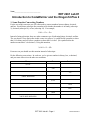
1
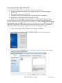
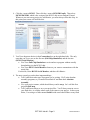
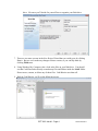
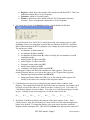
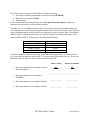
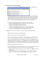
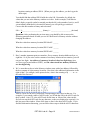
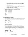
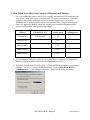
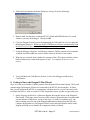
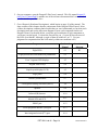
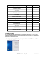
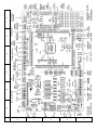
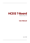
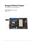
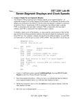
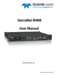
Name________________________________ EET 2261 Lab #1 Introduction to CodeWarrior and the Dragon12-Plus 2 1. Some Practice Converting Numbers For the rest of this semester you will often need to convert numbers between binary, decimal, and hex. Recall that a subscript after a number tells whether the number is in binary (subscript 2), decimal (subscript 10), or hex (subscript 16). For example, 11012 = 1310 = D16 Instead of using subscripts, there are other common ways of indicating binary, decimal, and hex. The way that we’ll use most often in this course is to place a % symbol before a number to show that it’s in binary and a $ before a number to show that it’s in hex. (No symbol before the number means that it’s in decimal.) Using this notation, %1101 = 13 = $D From now on you should use this notation instead of subscripts. Do the following conversions. In each row, you’re given a number in binary, hex, or decimal, and you must convert it to the other two notations. Binary Hex Decimal %1111 $10 255 %0001 0000 0000 $3FF 1024 2047 $800 %0010 0000 0000 0000 EET 2261 Lab #1 - Page 1 Revised 6/25/2014 2. Getting Started with CodeWarrior Freescale CodeWarrior is a very powerful piece of software that lets you: Examine and change the contents of the registers and memory locations inside the HCS12 chip. Write and test programs for the HCS12. Translate these programs into the binary code that the HCS12 understands. Download your translated programs to the HCS12 chip. Run your downloaded programs, and monitor the execution of the running programs. In the old days, you would need several pieces of software to perform these different tasks. Because CodeWarrior lets you perform all of these tasks, it’s called an Integrated Development Environment (abbreviated IDE). In this course you’ll learn how to use CodeWarrior to do all of the things listed above. This first lab will focus on the first item in the list: Examine and change the contents of the registers and memory locations inside the HCS12 chip. 1. Connect your Dragon12-Plus2 board to your computer’s USB port. 2. In the Windows Start menu, select CodeWarrior IDE. You’ll see the following: 3. Click the Create New Project button. CodeWarrior starts up its New Project Wizard, whose first screen looks like this: EET 2261 Lab #1 - Page 2 Revised 6/25/2014 4. Click the + next to HCS12. Then click the + next to HCS12D Family. Then select MC9S12DG256B, which is the version of the HCS12 chip on our Dragon12 board. Whenever you start a new project in CodeWarrior, you must always select this chip. At this point your screen will look like this: 5. You’ll see about ten choices in the Connections box on the right-hand side. The only ones that you’ll ever use are the first one (Full Chip Simulation) and the last one (HCS12 Serial Monitor). You’ll use Full Chip Simulation to write and test a program without actually downloading it to the HCS12 chip. You’ll use HCS12 Serial Monitor whenever you want to communicate with the actual chip. For this lab, select HCS12 Serial Monitor, and then click Next >. 6. The next screen lets you do three important things: Tell CodeWarrior what type of program you’re writing. We’ll write absolute assembly programs, so you must first uncheck C and then check Absolute Assembly. Give your project a name, which should always end in .mcp. Let’s call this first project Lab01.mcp. Tell CodeWarrior where to save your project files. You’ll always want to save to your flash drive, in a folder whose name is the same as your project. In the screen below, I’m saving to a folder named Lab01 inside some other folders on my flash EET 2261 Lab #1 - Page 3 Revised 6/25/2014 drive. Of course you’ll decide for yourself how to organize your flash drive. 7. There are two more screens in the New Project Wizard that you could get to by clicking Next >. But we won’t make any changes to those screens, so you can skip them by clicking Finish now. 8. Using Windows My Computer, take a look at the files on your flash drive. You should see that CodeWarrior has already created many files and folders inside the Lab01 folder. Do not move, rename, or delete any of those files. CodeWarrior uses them all. 9. Back in CodeWarrior, you’ll see the following screen: EET 2261 Lab #1 - Page 4 Revised 6/25/2014 Some people like getting a random Tip of the Day every time they start the program, but some people don’t. If you don’t want to see these tips in the future, remove the checkmark next to Show Tips on StartUp. Then, whether or not you removed the checkmark, click Close. 3. CodeWarrior’s Debugger If you were writing a program, there are some other steps that you would do now. You’ll learn those steps in future labs. But today we want to go right to CodeWarrior’s debugger, which lets us examine the registers and memory inside the HCS12 chip. 1. To start CodeWarrior’s debugger, either: Select Project > Debug from the menus Or press the F5 key on your keyboard Or click the green arrow/bug button in the toolbar 2. After a brief delay you’ll see the following screen: In the HOST Serial Communication Port, you must choose the right COM port for the USB port on your computer. In our labs, this is COM4:, so choose this now. Then click OK. 3. You’ll now see the main debugger screen, which has seven windows: Source, which we’ll care about when we’re writing and testing programs, but we’ll ignore for now. Data, which we’ll usually ignore. Command, which we’ll usually ignore. Assembly, which we’ll care about when we’re writing and testing programs, but we’ll ignore for now. EET 2261 Lab #1 - Page 5 Revised 6/25/2014 Registers, which shows the contents of the registers inside the HCS12. This is an important window that we’ll use frequently. Procedure, which we’ll usually ignore. Memory, which shows the contents of the HCS12’s thousands of memory locations. This is an important window that we’ll use frequently. 4. Let’s look more closely at the Register window, which should look like this: As you’ll learn in class, the HCS12’s central processing unit contains seven (or eight, depending on how you count them) registers that are central to the HCS12’s operation. Most of the instructions in HCS12 programs use or change the values in these registers. The registers are called: Accumulator A (abbreviated A) Accumulator B (abbreviated B) Accumulator D (abbreviated D), which is actually just Accumulators A and B combined together. Index Register X (abbreviated IX) Index Register Y (abbreviated IY) Program Counter (abbreviated PC) Stack Pointer (abbreviated SP) Condition Code Register (abbreviated CCR) The Register window also shows the contents two other registers. These are for advanced features that we won’t use in this course, so we’ll ignore these registers: Program Page Register (abbreviated PPAGE). Instruction Pointer (abbreviated IP). For us, the contents of this register will usually be the same as the contents of the Program Counter. 5. CodeWarrior has a special way of displaying the contents of the Condition Code Register. This register holds eight bits, and each bit has its own name: for example, the S bit, the X bit, the H bit, and so on. Each bit can have a value of 1 or 0. If its value is 1, CodeWarrior displays its name in black. If its value is 0, CodeWarrior displays its name in gray. Looking at your screen right now, record the value of each bit: S = ___ X = ___ H = ___ I = ___ N = ___ Z = ___ V = ___ C = ___ 6. By default, CodeWarrior displays the contents of the other registers in hex. That’s usually what we want, but occasionally it’s more useful to see the contents displayed in binary or in decimal. To change the display, place your mouse anywhere inside the Register window and right-click. Then roll over Format in the pop-up menu, and you’ll EET 2261 Lab #1 - Page 6 Revised 6/25/2014 see several choices. Click Bin, and you’ll see the registers contents displayed in binary. This lets us see how many bits each registers holds. (You may have to scroll to the right to see some of the bits.) Recalling that one byte equals eight bits, complete the following table: Register Number of Bits Number of Bytes A B D IX IY PC SP CCR 7. Now change the Format back from Binary to Hex. 8. The Register window not only lets us see what values are currently in the registers. It also lets us change these values. To change a value, simply double-click it and then type the new value. (The CCR is a little different. To change a bit’s value from 0 to 1 or from 1 to 0, double-click the bit’s name.) To practice doing this, set the register values to: A = $10, B=$1F, IX=$1000, IY=$2000, PC=$5000, SP=$3000, CCR: S = 0, X = 1, H = 1, I = 1, N = 1, Z = 0, V = 1, C = 0. Notice that D holds the combined values of A and B. As mentioned above, Accumulator D is actually just Accumulators A and B combined together. So you will always find that the value in D is just the combined values in A and B. Call me over to check your work.___________________ 4. The HCS12’s Memory Map Now let’s turn our attention from the Register window to the Memory window. First we need to know a little about how the HCS12’s memory is organized. The HCS12’s memory has thousands of memory locations. Each location has an address. The addresses range from $000000 to $3FFFFF, but in this course we will never use addresses beyond $FFFF. So as far as we’re concerned, the addresses range from $0000 to $FFFF. (Recall that the $ symbol indicates hex.) Given this restriction, how many memory locations (in decimal) do we have? _________________________ EET 2261 Lab #1 - Page 7 Revised 6/25/2014 The HCS12 chip contains three different kinds of internal memory: Electrically erasable programmable read-only memory (EEPROM) Random-access memory (RAM) Flash memory It also contains hundreds of internal registers called special-function registers, which have addresses and are treated a lot like memory locations. The table below is a simplified “memory map” for our system, showing the address ranges (in hex) assigned to the special-function registers and the different kinds of memory. Notice that the special-function registers are located at the low end of the system’s memory space, from address $0000 to $03FF. And the Flash memory is located at the high end of the memory space, from address $4000 to $FFFF. In between are the EEPROM and RAM. Address Range $0000 to $03FF $0400 to $0FFF $1000 to $3FFF $4000 to $FFFF Description Special-function registers EEPROM RAM Flash Using the numbers from the memory map, answer the following questions. For each question, give your answer in both hex and decimal. I’ve answered the first question for you. Be sure you understand why the answer to this first one is $400 and not $3FF. 1. How many addresses are assigned to specialfunction registers? Answer in hex Answer in decimal _____$400______ ______1024_____ ______________ ______________ ______________ ______________ ______________ ______________ 2. How many addresses are assigned to EEPROM? 3. How many addresses are assigned to RAM? 4. How many addresses are assigned to Flash? EET 2261 Lab #1 - Page 8 Revised 6/25/2014 5. Viewing the Contents of Memory 1. Now let’s look at CodeWarrior’s Memory window, which looks something like this: In the picture shown above, we’re viewing the contents of the chip’s memory locations from address $0080 through address $00AF. The first column in each row contains the starting address (in hex) of the locations displayed on that row. Following this address are the contents (in hex) of eight memory locations. Each memory location holds one byte, so we need two hex digits to show the contents of each memory location. For example, reading across the first row in the picture, we can see that: Memory location $0080 holds the value $00 (or %0000 0000 in binary) Memory location $0081 also holds the value $00 Memory location $0082 also holds the value $00 Memory location $0083 holds the value $20 (or %0010 0000 in binary) Memory location $0084 holds the value $05 (or %0000 0101 in binary) Memory locations $0085, $0086, $0087 all hold the value $00. Question: In the picture above, what hex value does memory location $0088 hold? ______ What hex value does memory location $008A hold? ______ What hex value does memory location $008F hold? ______ 2. Just as we saw above how to view the register contents in binary or decimal instead of hex, we can do the same thing with memory. To change the display, place your mouse anywhere inside the Memory window and right-click. Then roll over Format in the popup menu, and you’ll see several choices. Click Bin, and you’ll see the memory contents displayed in binary. Because binary notation takes up a lot more space than hex notation, you’ll probably now see only four memory locations listed on each row, instead of eight. 3. Change the Format back from Binary to Hex. 4. To view the contents of other memory locations, you can use the vertical scroll bar on the right side of the Memory window. But it’s often easier to do the following: Right-click anywhere inside the Memory window, and then click Address... from the pop-up menu. Type in the address (in hex) of the memory location whose contents you want to display. For example, do it now and type F810 to see the contents of memory EET 2261 Lab #1 - Page 9 Revised 6/25/2014 locations starting at address $F810. (When you type the address, you don’t type the dollar sign.) You should find that address $F810 holds the value $40. Remember: by default, the values that you see in the Memory window are in hex. In this example, CodeWarrior didn’t display a special symbol to remind you that the 40 is a hex number, but it is; and if you mistakenly think that it is decimal 40 instead, you will quickly get confused. Convert this hex number to binary and to decimal: $40 = %_______________________ (binary) = _______________________(decimal) Questions: After performing the previous steps, you should be able to answer the following questions based on what you see in CodeWarrior’s Memory window without changing the address. What hex value does memory location $F816 hold? ______ What hex value does memory location $F81C hold? ______ What hex value does memory location $F82E hold? ______ 5. Here’s another important point to remember: Every memory location holds one byte, or eight bits. So if you write out the contents of a memory location in hex notation, you will use two hex digits. An address of a memory location is four hex digits long (since we’ll never go beyond address $FFFF), and the value stored in a memory location is two hex digits long. 6. We’ve seen that each row in the Memory window starts with a hex address, followed by the hex contents of eight memory locations. But what is the additional information to the right of that? For example, in the picture below, what is the meaning of @ ....r. at the end of the first row? Answer: These are the ASCII characters corresponding to the values in that row. For example, if you consult a table of ASCII codes, you’ll find that $40 is the ASCII code for the @ symbol. Also, $72 is the ASCII code for the letter r. Most of the values in this first row are not the ASCII code for any character, so they are displayed as a period (.) in this last part of the window. Most of the time we don’t care about ASCII codes. If you find this information distracting, you can follow these steps to hide the ASCII characters: EET 2261 Lab #1 - Page 10 Revised 6/25/2014 Right-click anywhere inside the Memory window, and then roll over Display in the pop-up menu. Notice that ASCII has a checkmark next to it. Click ASCII to turn off the ASCII display. You can always turn it back on by following these same steps. Notice that CodeWarrior also lets you turn off the display of the addresses in the Memory window, but that would not be a good idea, since then you wouldn’t know which memory locations you’re looking at. 7. You now know how to see the value stored in any of the HCS12’s memory locations. Find and record the hex contents of the following memory locations: Address Contents (in hex) $0000 _____________ $0100 _____________ $FCAE _____________ $FFFF _____________ 6. Changing the Contents of Memory 1. The Memory window not only lets us see what values are currently stored in memory. It also lets us change these values. To change a value, double-click it and then type the new value. To practice doing this, set the following memory locations to the values shown: Address $2200 $2205 $221F $2222 Value $3D %1000 1001 $4C %1111 0000 Call me over to check your work.___________________ 2. There will be times when we want to assign the same value to all of the memory locations in a range of addresses. To do this, right-click anywhere inside the Memory window, and then select Fill…. A dialog box will open, in which you can specify a beginning address, an ending address, and the value to be assigned to all of the locations in the range you’ve specified. To practice doing this, fill the following ranges with the values shown: Address Range $1200 - $121F $1750 - $179F Value $7E %1010 0110 Call me over to check your work.___________________ EET 2261 Lab #1 - Page 11 Revised 6/25/2014 7. How Power Loss Affects the Contents of Registers and Memory 1. Let’s see whether the values in the HCS12’s registers and memory are lost when the chip loses power. In the table below, I’ve listed one CPU register (Accumulator A) and four addresses. One of these addresses is a special-function register, one is located in EEPROM, one is located in RAM, and one is located in Flash. Using the memory map from a few pages ago, identify which one is which, and record this information in the table’s second column. Then go on to Step 2 below. Register or Address Description (for example, Flash, RAM, etc.) Contents before cycling power Accumulator A CPU Register $33 Address $3002 $33 Address $0002 $33 Address $0802 $33 Address $5002 $33 Contents after cycling power 2. Use the debugger’s Register window to set Accumulator A’s value to $33, and use the Memory window to set the values of the four listed addresses to $33. 3. By default, CodeWarrior erases the HCS12’s Flash and EEPROM whenever you start the debugger. For now, we want to disable this feature, so select MONITOR-HCS12 > Communication… in the debugger’s menu bar. You’ll see the dialog box below: EET 2261 Lab #1 - Page 12 Revised 6/25/2014 4. Select the Load Options tab in this dialog box, and you’ll see the following: 5. Remove both check-marks, so that the HCS12’s Flash and EEPROM won’t be erased whenever you start the debugger. Then press OK. 6. Cycle the Dragon12 board’s power by unplugging the USB cable for a few seconds and then plugging it back in. When you do this, CodeWarrior will lose communication with the board, so you’ll have to close the debugger and then open it again. 7. Using the debugger’s Register and Memory windows, find the contents of Accumulator A and the four listed addresses, and record the values in the table’s last column. 8. What can you conclude about whether the contents of the CPU registers and the various kinds of memory are retained when power is lost? Use complete sentences in your answer. 9. You’re finished with CodeWarrior for now, so close the debugger and then close CodeWarrior. 8. Getting to Know the Dragon12-Plus2 Board Next, let’s start to get familiar with the features of the Dragon12-Plus2 trainer board. This board contains many input-output (I/O) devices connected to the HCS12 microcontroller. In future labs you will program the HCS12 to communicate with these devices, so you’ll need to be able to identify the devices, such as switches, LEDS, temperature sensor, speaker, keypad, and so on. 1. On the last page of this lab is a silkscreen diagram showing the layout of the Dragon12Plus2 board. (This page comes from one of the reference documents that I recommended you download to a flash drive, except on this copy I’ve added a coordinate grid—the letters running across the top of the diagram and numbers running down the left side.) Compare the diagram to a real Dragon12-Plus2 board, and notice that the labels on the diagram will help you to identify the components on the real board. EET 2261 Lab #1 - Page 13 Revised 6/25/2014 2. On your computer, open the Dragon12-Plus2 user’s manual. This file, named dragon12plus2_hcs12_manual.pdf, is another one of the reference documents that I recommended you download to your flash drive. 3. Go to Chapter 4 (Hardware Descriptions), which begins on page 24 of the manual. The short sections of this chapter describe components on the Dragon12-Plus2 board. Most of these descriptions contain technical terms that you won’t understand yet, but skim each description now and use the silkscreen diagram to locate each component on the real Dragon12 board. In the table below, record the grid coordinates of each component as you locate it on the board. I’ve done the first one for you. (I wrote B3 because most of the LEDs lie within B3, although a couple of them lie within A3 or C3. Use your judgment for components that don’t fall entirely within one coordinate cell.) Component Section of Manual Location on diagram Eight LEDs 4.1 B3 Eight-position DIP switch and four pushbuttons 4.2 Four 7-segment LED displays 4.3 Keypad with 16 keys 4.4 Liquid-crystal display (LCD) 4.5 Logic probe 4.6 Trimmer potentiometer 4.7 Two digital-to-analog converters (DACs) 4.8 Speaker 4.9 Infrared (IR) detector 4.10 Two serial communication interface (SCI) ports, labeled SCI0 and SCI1. 4.11 RS485 port 4.12 Serial peripheral interface (SPI) port 4.13 Inter-integrated circuit (I2C) port 4.14 EET 2261 Lab #1 - Page 14 Revised 6/25/2014 Red-green-blue (RGB) LED 4.15 VGA camera interface Reset switch Temperature sensor Relay output Four servo motor outputs Light sensor Two mode-select switches Bluetooth interface Abort switch H-bridge outputs Capacitive touch switch 9. The Reset Switch One important feature that you located above is the Dragon12 board’s Reset switch. In future weeks there will be times when you need to reset the board using this switch. Let’s look at some of the effects of pressing this switch. 1. Connect your Dragon12 board to your computer and then start CodeWarrior. You’ll see the following dialog box: EET 2261 Lab #1 - Page 15 Revised 6/25/2014 2. You didn’t save anything important in the project that you created near the beginning of this lab, but let’s open that project rather than creating a new project. Either: Press the Load Previous Project button in the dialog box shown above, then select Lab01.mcp, and then press Open Project. Or close the dialog box shown above and select File > Open… in CodeWarrior’s menu bar. Then navigate to the Lab01 folder on your flash drive and open the file named Lab01.mcp. 3. Let’s see whether the values in the HCS12’s registers and memory are lost when you reset the chip. In the table below, I’ve listed one CPU register and four addresses. In the second column, say whether each address is a special-function register, EEPROM, RAM, or Flash. Then go on to Step 4 below. Register or Address Description (for example, Flash, RAM, etc.) Contents before pressing Reset Accumulator B CPU Register $66 Address $0603 $66 Address $5003 $66 Address $0003 $66 Address $2003 $66 Contents after pressing Reset 4. Use the debugger’s Register window to set Accumulator B’s value to $66, and use the Memory window to set the values of the four listed addresses to $66. 5. Press the Dragon12 board’s Reset switch. When you do this, CodeWarrior will lose communication with the board, so you’ll have to close the debugger and then open it again. 6. Using the debugger’s Register and Memory windows, find the contents of Accumulator B and the four listed addresses, and record the values in the table’s last column. 7. What can you conclude about whether the contents of the CPU registers and the various kinds of memory are retained when you reset the chip? Use complete sentences in your answer. EET 2261 Lab #1 - Page 16 Revised 6/25/2014 F E D C B 3 4 5 2 1 A